Embed Size (px)
Citation preview

FLOATING BALL VALVES

BF 1 1 A A A 1 L
VALVE TYPE BORE PRESSURE CLASS
BODY MATERIAL
TRIM MATERIAL
SEAT MATERIAL
END CONNECTION OPERATOR
BU 1 PIECE BALL VALVE 1 FULL 1 CLASS 150 A A216-WCB(A105) A CS+ENP A PTFE 1 RFE ELECTRIC
ACTUATORBF 2 PIECE BALL VALVE 2 REDUCED 2 CLASS 300 B A351-CF8(F304) B 304 B RTFE(GLASS) 2 RTJ
BN 3-WAY BALL VALVE (90°) 3 CLASS 600 C A351-CF8M(F316) C 316 C RTFE(CARBON)P PNEUMATIC
ACTUATORBY 3-WAY BALL VALVE (120°) 4 CLASS 900 D A351-CF3(F316L) D 304L D SUPER TEFLON
B6A F6A BALL VALVE 5 CLASS 1500 E A351-CF3M(F316L) E 316L E PFAG GEAR
OPERATORBFM METAL SEAT BALL VALVE F A351-CN7M F ALLOY 20 F PEEK
BFC CRYOGENIC BALL VALVE G A217-WC1 G 410 G NYLON B BARE STEM
BP POCKETLESS BALL VALVE H A217-WC6(F11) Q DUPLEX H METAL L LEVER
BJ STEAM JACKET J A217-WC9(F22) R MONEL I PCTFE
K A352-LCC S HASTELLOY J DEVLON®
L A352-LC2 T TITANIUM K GRAPHITE
M A352-LC3 X OTHER X OTHER
N A352-LCB(LF2)
P A217-C5
Q DUPLEX
R MONEL
S HASTELLOY
T TITANIUM
U INCONEL
X OTHER
FIGURE NUMBER CODING CHART
DESIGN STANDARDS
Item Standard
Shell Wall Thickness Class 150, 300 and 600 ANSI B16.34 Pressure Temp Rating ANSI B16.34 Pressure Test Class 150, 300 and 600 API 598 Face to Face Dimensions ANSI B16.10 End Flange Dimensions ANSI B16.5 Mounting Pad Class 600 ISO 5211Visual Casting Inspection MSS SP-55Fire Test API 607 4th Edition & API 6FAGeneral Design Class 600 ANSI B16.34 & API 6DMaterial Requirements NACE MR0175 Latest EditionQuality Control API 6DValve Design & Construction API 608
2 3
QUALITYFORCE® Valve quality is guaranteed by the strictest adherence to the ISO 9000 and API Q1 audited quality standards. We at FORCE® Valve have dedicated ourselves to providing the highest quality valve products to meet our customers expectations. FORCE® Valves are manufactured in strict accordance with all applicable ANSI, API and other standards. Every valve is tested and documented to the API 598 and API 6D testing requirements. Our valves are manufac-tured to comply with NACE standards with complete MTR traceability.

SPECIFICATIONS
· Full Bore & Reduced Bore · Metal to Metal Construction· Floating Ball Design · Lip Seal or Plate Seal· Locking Device · NACE Standard· Blow-Out Proof Stem · Fire Safe Design / Non Fire Safe Design· Flexible Cavity Relief Seats · Two Radius of Ball Edge for Long Life Cycle· Anti-Static Grounding Device · Double “D” Stem· ISO Mounting Pad
APPLICABLE SEAT MATERIALS · PTFE· RTFE (15% Glass Filled)· RTFE ( 25% Carbon Filled)· Super Teflon· PFA Seat· Peek Seat· Nylon Seat· Metal· PCTFE· Devlon®· Graphite· Other materials can be supplied upon request
ISO mounting Pad
Investment casting or Shell molded castings
Materials of construction to meet NACE requirements
Blow-out proof stem
Open & closed locking device integral with travel stopAdjustable multi-ring packing
Fire safe tested to the requirements of API 607 4th Edition
Flexible cavity-relief seats
Captured spiral wound gasket with secondary metal to metal body sealing
Split body construction for easy maintenance
2 3

FLOATING BALL VALVE FEATURES
GeneralFORCE floating ball valves are designed in accordance with API 608 or ISO17292(BS5351) for ANSI Class ratings 150 to 2500, Nominal sizes from 1/2” to 12”. Valves have been designed for use with various combinations of materials such as; Carbon Steel, Low Carbon Steel, Special Alloy, Stainless Steel, Monel, Inconel.
Body Joint ConstructionThe one piece unibody end entry design, graphite ring or o-ring, Viton (upon request) seals ensure absolute seal integrity. The two piece bolted body designs include a tight toleranced overlapping metal fit between the body and the adapter to minimize any pos-sibility of movement due to pipeline stress. A special high temperature spiral wound stainless steel / grafoil filled gasket is utilized for absolute seal. This gasket is encapsulated by the body and adapted on all four sides. Body and adaptors are dimensioned for metal contact to ensure correct gasket crush.
Blow-Out Proof StemStem is made separately from the ball, anti blow-up design withsuitable PTFE and graphite rings and antistatic device.The lower end of the stem is designed with an integral collar to beblowout-proof. It also functions as the backseat for assured stemsealing. (Fig. 1)
Anti-Static DeviceAll floating flanged ball valves include dual groundingsystems from stem to ball and stem to body. Valve testing toISO17292(BS5351) was performed for all sizes, and witnessedby a third party inspection company.An antistatic feature is provided to ensure electrical continuity forassured stem sealing. (Fig. 2)
Live Loaded Gland FlangeLive loading is designed to provide gland load retention,compensating for expected in-service consolidation of the packing.A set of Belleville-Spring Washers are used on each gland followerflange and therefore reduce fugitive emissions from the stempacking. FORCE standard Belleville-Spring Washers are protectedby a weatherproof cap to keep them free from environmentalcontamination, resulting in a long stable life. (Fig. 3)
Top WorksStem head design provides mounting of the lever handle always inparallel to the flow passage. Facility for mounting a locking device for prevention of accidental valve operation is provided (Fig. 4)
Packing
BodyGasket
Stem
Ball
Packing
BodyGasketStem
Antistatic device
Ball
Live loading
Gland flange
Gland bolt
Body
Gland flange
Lock
Fig. 1
Fig. 2
Fig. 3
Fig. 4
4 5

Fire Safety
All fire-safe valves conform toAPI 607 and API 6FA standards. When a fire accident occurs at a jobsite where the valve is operating, components such as seat ring, stem back seat, stem packing and mid-flange gasket which made of non-metallic material such as PTFE were broken or destroyed.However, FORCE’s particu-larly metal to metal added seal seated designed ball valves can effectively control external or interal leakage.FORCE’s soft seated fire safety designed as follows:
Longevity of Life Special consideration was devoted to the attainment of enhanced life and operation of our valve throughout design, development, testing and manufacturing stages.Valve designs combined with the selection of advanced mate-rials are such that long periods of inactivity should not affect the operations of effiiciency.
Contact between ball and valve shell
Stem
Packing
Body
Gasket
Ball
Contact between stem and valve shell
Fig. 5 (Before Fire) Fig. 6 (After Fire) Metal-to-metal contact
Fig. 7 (Before Fire) Fig. 8 (After Fire) Metal-to-metal contact
Fig. 9 (Before Fire) Fig. 10 (After Fire) Metal-to-metal contact
Valve shell coupling flanges of split body design
Body
Seal
Body cap Body capGasket
4 5
Body Body
BallBall
Body
Stem
Packing
Body
Gasket
Ball

PARTS LIST AND MATERIAL SPECIFICATIONS (TYPICAL) MODEL BU
No. Part Name Qty. Carbon Steel Stainless Steel
1 Body 1 A216-WCB A351-CF8M
2 Retainer 1 A216-WCB A351-CF8M
3 Ball 1 A351-CF8M A351-CF8M
4 Stem 1 A276-316 A276-316
5 Gland 1 A276-304 A276-304
6 Gland Flange 1 A351-CF8 A351-CF8
7 Stopper 1 A240-304 A240-304
8 Handle 1 Ductile Cast Iron Ductile Cast Iron
No. Part Name Qty. Carbon Steel Stainless Steel
9 Thrust Washer 1 PTFE PTFE
10 Gland Packing 1 Set Graphite+Carbon Fiber Graphite+Carbon Fiber PTFE
11 Seat 2 RTFE RTFE
12 Gasket 1 Graphite Graphite
13 Gasket 1 PTFE PTFE
14 Stem Bearing 1 Set RTFE RTFE
15 Handle Bolt 1 Set A193-B8 A193-B8
16 Gland Bolt 2 A193-B8 A193-B8
8
2
12
13
11
3
11
1
4
9
14
10
5
6
7
16
8
15
6 7

6 7
ENGINEERING DATA MODEL BU
Pressure / Temperature Ratings for Model BU
The dotted lines indicate Working Pressures for casting stainless steel bodies. (ASTM A351-CF8M)The operating temperature of the valves is limited by the material of seat and seal.
Torque Data for Model BU
Seat Material: Reinforced PTFE. When selecting an actuator, add a 25% safety factor to the required torque.
REDUCED PORT 2" ~ 6" REDUCED PORT 8" ~ 10"

PARTS LIST AND MATERIAL SPECIFICATIONS (TYPICAL) MODEL BF
No. Part Name Qty. Carbon Steel Stainless Steel
1 Body 1 A216-WCB A351-CF8M
2 Retainer 1 A216-WCB A351-CF8M
3 Ball 1 A351-CF8M A351-CF8M
4 Stem 1 A276-316 A276-316
5 Gland 1 A276-304 A276-304
6 Gland Flange 1 A351-CF8 A351-CF8
7 Stopper 1 A240-304 A240-304
8 Handle 1 A283-D, A536
9 Thrust Washer 1 PTFE PTFE
No. Part Name Qty. Carbon Steel Stainless Steel
10 Gland Packing 1 Set Graphite+Carbon Fiber Graphite+Carbon Fiber
11 Seat 2 RTFE RTFE
12 Gasket 1 316Hoop+Graphite 316Hoop+Graphite
13 Stem Bearing 1 RTFE RTFE
14 Cap Bolt 1 set A193-B7 A193-B8
15 Cap Bolt Nut 1 set A194-2H A194-8
16 Gland Bolt 2 A193-B7 A193-B8
17 Handle Bolt 1 A193-B8 A193-B8
2
12
15
11
3
111
4
14
9
13
10
5
6
7
16
17
8
8 9

ENGINEERING DATA MODEL BF Pressure / Temperature Ratings for Model BF
The dotted lines indicate Working Pressures for casting stainless steel bodies. (ASTM A351-CF8M)The operating temperature of the valves is limited by the material of seat and seal.
Torque Data for Model BF
Seat Material: Reinforced PTFE. When selecting an actuator, add a 25% safety factor to the required torque.For other sizes not listed, contact Force.
FULL PORT 1/2" ~ 10" REDUCED PORT 2" ~ 8"
8 9
Temperature(°C)
Temperature(°F)
Pres
sure
(Kg/
Cm G
)
Virgin PTFE SEAT
-30
50
100
0 50 100
RTFE SEAT
2
-22 12232 212
Pres
sure
(psig
)
150 200
EPDM
250
711
1422
302 392 482
PCTFE SEAT
DEVLON SEAT
Temperature(°F)122
RTFE SEAT
50
Temperature(°C)
2
Pres
sure
(Kg/
Cm G
)
Virgin PTFE SEAT
-30 0
50
100
-22 32
Pres
sure
(psig
)
100 150
212 302
200 250
392
711
1422
482
CLASS600#BODY
CLASS600#BODY
CLASS3 00#BODY
CLASS15 0#BODY
REDUCED PORT 2"~8"FULL PORT 1/ 2"~ 10 "
MODEL BF MODEL BF
VITON
PEEK SEAT
NYLON SEAT
PCTFE SEAT
DEVLON SEAT
VITON
EPDM
PEEK SEAT
NYLON SEAT

10 11
FLOATING BALL VALVES ANSI 150 & 300BU SeriesReduced bore: sizes 1-1/2” to 12”For pipeline, oilfield or process Industry
NPS 1 1/2 2 2 1/2 3 4 6 8 10 12
d(Bore)
1 1.5 2 2.32 3 4 5.67 7.32 8.66
25 38 51 59 76 102 144 186 220
L6.5 7 7.5 8 9 10.5 11.5 13 14
165 178 191 203 229 266.7 292 330 355.5
H4 5 5.6 6.1 6.7 8.1 10.9 12.8 16.5
102 127 142 154 170 206 278 325 419
Cv Value 106 153 276 317 449 899 1,180 3,277 4,350
CLASS 150 DIMENSIONS Units : inch / mm
NPS 1 1/2 2 3 4 6 8 10
d(Bore)
1 1.5 2.32 3 4.1 5.67 7.4
25 38 59 76 102 144 203
L7.5 8.5 11.14 12 15.87 16.5 18
191 216 283 305 403 419 459
H4 5 6.1 6.7 8.1 10.9 12.8
102 127 154 170 206 378 325
Cv Value 106 156 361 533 1,039 1,402 3,277
CLASS 300 DIMENSIONS Units : inch / mm
Standard Materials Body: Carbon Steel (WCB, LCB) Stainless Steel (CF8, CF8M) Ball: Stainless Steel (CF8, CF8M) Stem: SS304, SS316 Seats: PTFE, RTFE, Modified TFE
H
L
10 11
FLOATING BALL VALVES ANSI 150 & 300BF Series
Full bore: sizes 1/2” to 12” For pipeline, oilfield or process Industry
Full bore: sizes 1/2” to 2”For oilfield or process Industry
Standard Materials Body: Carbon Steel (WCB, LCB) Stainless Steel (CF8, CF8M) Ball: Stainless Steel (CF8, CF8M) Stem: SS304, SS316 Seats: PTFE, RTFE, Modified TFE
Standard Materials Body: Carbon Steel (WCB, LCB) Stainless Steel (CF8, CF8M) Ball: Stainless Steel (CF8, CF8M) Stem: SS304, SS316 Seats: RTFE, Nylon, PEEK
Standard Materials Body: Carbon Steel (WCB, LCB) Stainless Steel (CF8, CF8M) Ball: Stainless Steel (CF8, CF8M) Stem: SS304, SS316 Seats: Nylon, RTFE or Devlon®, PEEK
CLASS 150 DIMENSIONS Units : inch / mm
CLASS 300 DIMENSIONS Units : inch / mm
CLASS 600 DIMENSIONS Units : inch / mm
CLASS 900 & 1500 DIMENSIONS Units : inch / mm
FLOATING BALL VALVES ANSI 900 & 1500 BF Series
NPS 1/2 3/4 1 1 1/2 2 2 1/2 3 4 6 8 10 12d
(Bore)0.5 0.75 1 1.5 2 2.5 3 4 6 8 10 1213 19 25 38 51 64 76 102 152 203 254 305
L 4.25 4.61 5 6.5 7 7.5 8 9 15.5 18 21 24108 117 127 165 178 191 203 229 394 457 533 610
H 3.3 3.5 4 5 5.6 6 6.7 8.1 13.1 16 18.9 21.384 88 102 127 142 152 170 206 331 406 480 540
Cv Value 26 61 113 270 470 740 1,250 2,250 5,200 9,550 15,050 23,050
NPS 1/2 3/4 1 1 1/2 2 3 4 6 8 10d
(Bore)0.5 0.75 1 1.5 2 3 4 6 8 1013 19 25 38 51 76 102 152 203 254
L 5.5 6 6.5 7.5 8.5 11.13 12 15.86 19.75 22.38140 152 165 191 216 283 305 403 502 568
H3.3 3.5 4 5.2 5.8 6.8 8.1 13.1 16 18.984 88 102 127 147 173 206 331 406 480
Cv Value 26 61 113 270 470 1,100 2,150 5,150 9,450 15,050
FLOATING BALL VALVES ANSI 600BF Series Full bore: sizes 1/2” to 6” Reduced bore: sizes 2” to 8” For oilfield or process Industry
NPS 1/2 3/4 1 1 1/2 2x 1 1/2 2 3X2 3X3 4X3 4X4 6X4 6X6 8x6d
(Bore)0.51 0.75 1 1.5 1.5 2 2 3 3 4 4 6 613 19 25 38 38 51 51 76 76 102 102 152 152
L 6.5 7.5 8.5 9.5 11.5 11.5 14 14 17 17 22 22 26165 190 210 241 292 292 356 356 432 432 559 559 660
H3.54 3.66 3.94 4.96 4.96 5.31 5.6 6.7 6.7 8.1 8.1 13.1 13.190 93 100 126 126 135 142 170 170 206 206 331 331
Cv Value 21 44 75 239 165 450 250 1,050 650 1,900 840 4,650 2,200
NPS 1/2 3/4 1 1 1/2 2d
(Bore)0.51 0.75 1 1.5 213 19 25 38 51
L 8.5 9 10 12 14.5216 229 254 305 368
H 3.9 4 4.5 5.7 6.999 102 115 144 176
Cv Value 14 34 60 180 380
H
L
H
L
H
L
H
L

12 13
MATERIALS BODY & TRIM MATERIAL
CARBON STEEL A 105 A216 WCB A216 WCC
LOW TEMPERATURE CARBON STEEL A 350 LF2 A352 LCB A352 LCC
LOW ALLOY STEEL AISI 4140 A694 F65 A694 F52A694 F60 A350 LF3 API 6A 60K(A694 F60 Mod)
MARTENSITIC STAINLESS STEEL A182 F6A A182 F6NMA217 CA15 A487 CA6NM
AUSTENITIC STAINLESS STEELA182 F316 A182 F316LA182 F316LN-Mod. A182 F347A182 F44(6% Mo) A182 FXM-19(UNS S31254) (Nitronic 50)A351 CF8M A351 CF3A351 CF3M PRECIPITATION HARDENING STAINLESS STEEL A564 Gr 630 H 1150M (UNS S 17400)
SEAT INSERT & SEAL MATERIALS OPERATING (DYNAMIC) LIMITS*
MATERIAL TEMPº CPRESSURE
CLASSSIZE
MIN. MAXSEAT
INSERTSEAL
SEAT INSERT
SEAL
Nylon SMX -40 120 2500 N/A 64” N/ALauramid (Nylon 12G) -60 100 2500 N/A 64” N/A
Devlon (Nylon 6) -60 140 2500 N/A 64” N/APeek -60 220 2500 N/A 36” N/A
PTFE Glass Filled (25%) -100 200 600 N/A 24” N/APTFE Carbon Filled (25%) -100 180 300 N/A 24” N/A
PCTFE -196 150 2500 N/A 36” N/AHNBR-Therban -40 150 600 2500 64” 64”FKM A (Viton A) -29 180 600 2500 64” 64”
FKM GLT (Viton GLT) -40 180 600 2500 64” 64”FKM AED -29 180 600 2500 64” 64”
PTFE + Elgiloy Springs -196 200 N/A 2500 N/A 36”
NICKEL ALLOYSIncoloy 825 (UNS N08825)Inconel 625 (UNS N06625)Inconel 750 (UNS N07750)Monel 400Monel K500
Incoloy 925 (UNS N09925)Inconel 718 (UNS N07718)
DUPLEX STAINLESS STEELA181 F51 (UNS S31803)A182 F53 (UNS S31750)A182 F55 (UNS S31760)A890-4A (UNS S31803)A890-6A (UNS S32760)

12 13
MATERIAL FOR SEALING AND SEAT INSERTMaterial General Temperature Range USE / Characteristics Not Recommended for Properties
FM (Viton A) -13° F - 400° F (- 25° C ~ 204° C)
aliphatic hydrocarbons (petro-leum oil, mineral oil/grease, fuel oils, butane, propane, natural gas), aromatic hydrocarbons (benzene, toluene), chlorinated hydrocarbons, high vacuum, most acids/chemicals
brake fluid with glycol base, ammonia gas, amines, alkalis, acetone, skydrol, ethyl acetate, superheated steam, polar sol-vents (ketone, acetone, acetic acid, etc), low molecular esters and ethers
excellent resistance for wear, ozone, weather, aging, compression set, permeation
FKM(Viton GLT) -50° F - 400° F ( -45°C ~ 204° C )
extended low temperature ser-vice over Viton A. Excellent for water, steam and mineral acids in addition to use of Viton A
same as those of Viton A similar to those of Viton A except a little inferior compression set and permeability
NBR(Buna-N, Nitrile)
-35° F - 212° F (-37° C ~ 100° C)
aliphatic hydrocarbons (petro-leum oil, mineral oil/grease, fuel oils, butane, propane, natural gas) dilute acids, alkali, and salt solutions at low temperature, water
fuels of high aromatic content aromatic hydrocar-bons (benzene), chlorinated hydrocarbons, polar solvents (ketone, acetone, acetic acid, ethylene-ester), strong acid, glycol based brake fluid, ozone, weather and atmospheric aging
good resistance for wear, compression set, perme-ation
PTFE -400° F - 450° F (-240° C ~ 232° F)
almost all chemicals and solvents including strong acid and alkali, high and very low temperature service.
high mechanical loading weather resistance, thermal stability, low friction
Nylon 6 + MOS2 -65° F - 250° F (-54° C ~ 121° C)
aliphatic and aromatic hydro-carbons, ketones, acetone, ethers, weak alkalis, and acids, inorganic salt solutions
strong acids and alkali, strong ammonia, sodium hydroxide
excellent load bearing, strength and rigidity, self lubricating, good abrasion resistance
PEEK (polyethereth
erketon)-40° F - 500° F (-40° C ~ 260° C)
superb chemical resistance including alcohols, acids, ammonia, esters, halogenated organics, hydrocarbons and inorganics
some strong acids - nitric, chromic, sulfuric, benzene sul-fonic acids and aqua regia, etc, some inorganics - bromine, chlorine and fluorine, etc.
good high temperature performance, wear resis-tance, very low smoke and toxic gas emission, good hydrolysis resistance
Polymite - 65° F - 275° F 185° F, water based fluids (-54° C ~ 135° C)
petroleum and water based fluids, phosphate ester fluids, some chlorinated fluids and solvents, ketones, ethylene base glycols
strong acid, alcohols, brake fluids, dry chlorine, water over 185°F
very high sealability, tear strength, abrasion and extrusion resistance
TEMPERATURE LIMITS OF METAL PARTS
Forging Casting Low Temperature High Temperature
A105 A216 WCB -20° F (-29° C) 800° F (426° C)
A350 LF2 A352 LCB, LCC -50° F (-46° C) 650° F (343° C)
A182 F 316 A351 CF8M -425° F (-254° C) 1500° F (815°C)
TYPICAL GASKET SPECIFICATIONSType Material Low Temperature High Temperature Max. Pressure
Spiral wound 316 SS + Graphite -420° F (-250° C) 1500° F (815° C) 6,250 psi (430bar)
Spiral wound 316 SS + PTFE -200° F (-129° C) 450° F (232° C) 6,000 psi (415bar)
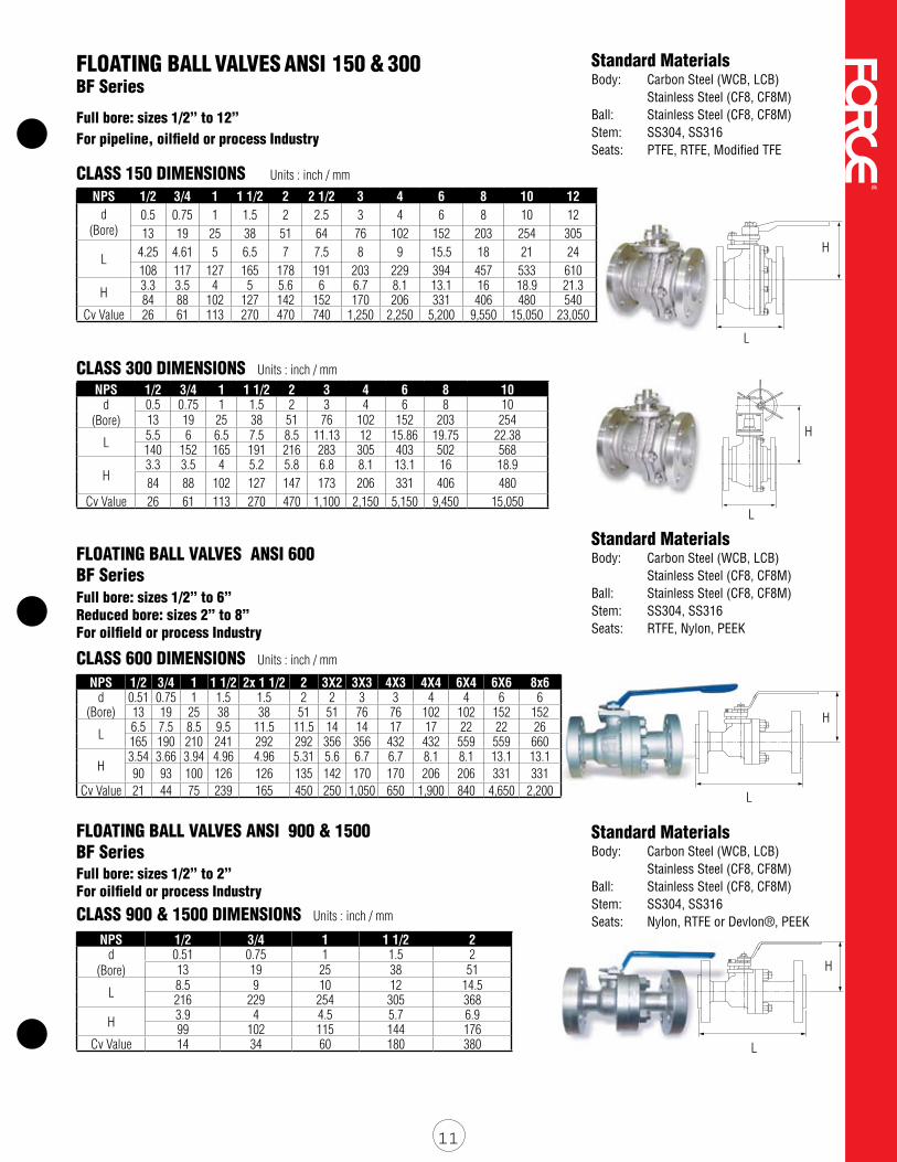
GEAR ACTUATOR DATAValve AutomationFORCE® is able to offer a comprehensive package of control equipment including actuators, switches, solenoids and positioners. Detail of actuator are available on request.
Gear OperatedThe gear operator can be furnished upon request
Model No. Dimension D E G K J M L P Flange Size
Gear Ratio
Max. Torque Weight
inch lb N-m lb kg
SBWG-00 inch 6.26 2.32 11.81 5.63 1.54 1.58 3.11 2.76 F10 34:1 11948 1350 13.23 6
mm 159 59 300 143 39 40 79 70
SBWG-01 inch 7.64 2.72 15.75 6.58 1.81 1.97 3.78 3.94 F14 42:1 19674 2223 24.25 11
mm 194 69 400 167 46 50 96 100
SBWG-02 inch 8.94 3.27 19.69 10.59 2.17 2.09 4.25 5.12 F16 42:1 24585 2778 41.89 19
mm 227 83 500 269 55 53 108 130
SBWG-03 inch 10.59 3.9 23.62 12.72 2.52 2.56 5.08 5.12 F16 43:1 30205 3413 74.96 34
mm 269 99 600 323 64 65 129 130
SBWG-04 inch 13.19 5.00 27.56 15.63 3.03 2.87 5.91 7.87 F25 50:1 40976 4630 119.05 54
mm 335 127 700 397 77 73 150 200
SBWG-04-1S inch 13.19 5.00 27.56 15.63 3.03 2.87 5.91 7.87 F25 153:1 111466 12595 158.73 72
mm 335 127 700 397 77 73 150 200
SBWG-05 inch 15.75 6.30 31.5 17.72 3.03 3.15 6.18 9.06 F30 50:1 46834 5292 163.14 74
mm 400 160 800 450 77 80 157 230
SBWG-05-1S inch 15.75 6.30 31.5 20.47 3.03 3.15 6.18 9.06 F30 153:1 130042 14694 202.82 92
mm 400 160 800 520 77 80 157 230
SBWG-06 inch 19.8 8.00 35.43 21.65 3.62 3.98 7.6 10.24 F35 55:1 57932 6546 302.03 137
mm 503 203 900 550 92 101 193 260
SBWG-06-1S inch 19.8 8.00 35.43 23.62 3.62 3.98 7.6 10.24 F35 213:1 199514 22544 392.42 178
mm 503 203 900 600 92 101 193 260
14 15
E G
K
J
L
M
P DD

GENERAL TERMS AND CONDITIONSNOTE: FORCE Industries Inc. and Seller will be used interchangeably.1. Warranty - All of FORCE Energy Products Inc. (Seller) products are warranted to be free from manufacturing defects for a period of one(1) year from the date of shipment, and if found to be defective within that period the product will be replaced with no charge to Buyer,only if (1) the product was used as recommended and in accordance with approved installation and operating practices (2) product fail-ure resulted from a manufacturing defect and not from damage in transit or damage due to corrosive, abrasive, or other wear normallyto be expected in the use of the product involved and (3) that the written notice of such defect is delivered to FORCE Energy Products Inc during such on (1) year period. No labor cost or other expense or liability will be assume. THIS EXPRESS WARRANTY IS IN LIEUAND EXCLUDES ALL OTHER WARRANTIES, GUARANTEES, OR REPRESENTATIONS EXPRESS OR IMPLIED. THERE ARE NO IMPLIEDWARRANTIES OR MERCHANTIBILITY OR OF FITNESS FOR A PARTICULAR PURPOSE.2. PURCHASER’S REMEDIES - The Purchaser’s remedies with respect to any product furnished by FORCE Energy Products Inc. hereunderthat is found not to be in conformity with the terms and conditions of the contract because of breach of contract, breach of expressor implied warranty or negligence shall be limited exclusively to the right of replacement of such defective product or, at our option,repayment of our sale price of the product. In no event shall FORCE Energy Products Inc. be liable for claims (based upon breach of contract,breach of express or implied warranty, negligence or any other reason) for any other damages, whether direct, immediate, foreseeable,consequential or special or for any expenses incurred by reason of the use or misuse, sale or fabrication of products which do or donot conform to the terms and conditions of the contract.3. ACCEPTANCE OF ORDERS - All orders are subject to acceptance by FORCE Energy Products Inc. No assignment of the Purchaser’s rightsmay be made without the written consent ofFORCE Energy Products Inc4. REMITTANCES - All accounts are payable in United States funds free of exchange, collection, or any other charges. If in the solediscretion of FORCE Energy Products Inc., the financial condition of the Purchaser at any time so requires, FORCE Energy Products Inc. retains theright to require full or partial payment in advance. Terms: 30 Days5. PARTIAL SHIPMENTS AND PAYMENTS - FORCE Industries Inc. reserves the right to make partial shipments from time to time, and torender invoices therefore which shall be due and payable as provided in said invoiced in the paragraphs above titled “Remittances” and“Terms of Payment” overleaf. If the Purchaser becomes overdue in any such partial payment, FORCE Energy Products Inc. shall be entitledto suspend work and/or avail itself of other legal remedies.6. TAXES - Unless otherwise specifically noted, the amount of any sales, occupancy, excise tax, of any nature, federal, state or local for Seller is legally liable, either initially or through failure of payment by Purchaser, shall be in addition to the price quoted and Purchaser agrees to pay the same to FORCE Energy Products Inc.7. SHORTAGES AND DAMAGES IN TRANSIT - All claims for loss, damages, shortages, etc. must be made within five days after receipt of shipment, but loss or damage to materials in transit is the responsibility of the carrier.8. DELAYS - All promises of shipment are estimated as closely as possible, and FORCE Energy Products Inc. will use our best efforts to shipwithin the time promised but do not guarantee to do so, and assume no liability for not doing so. Materials stated to be in stock are subject to prior sale.9. CHANGES, CANCELLATION AND SUSPENSION - The order or contract are subject to change, cancellation or instruction to suspendor delay work or delivery only upon receipt of written notification and consent. Orders for special fittings (usually P.O.A. items) maybe changed and/or cancelled only upon receipt of written instructions with a tacit understanding and agreement to make payment forwork already performed and material used.10. RETURN OF MATERIAL - No product of Seller may be returned without Seller’s written consent. All goods returned are subject toa handling charge plus freight in both directions and charges for any required reconditioning, unless otherwise specified in writing byFORCE Industries Inc.11. GOVERNING LAW - The contract shall be governed by, construed, and enforced in accordance with the laws of the State of Texas.12. NO WAIVER - The failure of Seller, to insist, in any one or more instances, upon the performance of any of the terms, covenants,or conditions of the contract or to exercise any right there under shall not be construed as a waiver or relinquishment of the futureperformance of any such term, condition, or the exercise of any other rights under the contract.13. PURCHASER’S ACCEPTANCE OF ABOVE CONDITIONS - FORCE ENERGY PRODUCTS INC. IS NOT BOUND BY ANY TERMS ON THE PUR-CHASER’S ORDER FORM OR ANY OTHER DOCUMENT EMANATING FROM THE PURCHASER WHICH ATTEMPT TO IMPOSE ANYCONDITION AT VARIANCE WITH SELLER’S TERMS AND CONDITIONS OF SALE WHICH ARE INCLUDED HEREIN OR STATED ONSELLER’S PACKAGES, INVOICES AND TECHNICAL DATA SHEETS. SELLER’S FAILURE TO OBJECT TO PROVISIONS CONTAINED THEAFORMENTIONED FORMS OF THE PURCHASER SHALL NOT BE DEEMED A WAIVER OF THE PROVISIONS OF C&C INDUSTRIESINC.’S TERMS AND CONDITIONS OF SALE WHICH SHALL CONSTITUTE THE ENTIRE CONTRACT BETWEEN SELLER AND THEPURCHASER. NO WAIVER ALTERATION OR MODIFICATION OF THE TERMS AND CONDITIONS IN THIS DOCUMENT SHALL BE BIND-ING UNLESS IN WRITING AND SIGNED BY AN AUTHORIZED REPRESENTATIVE OF SELLER STENOGRAPHIC OR CLERICAL ERRORSARE SUBJECT TO CORRECTION.14. FREIGHT POLICY - All prices and shipments are F.O.B, Houston, Texas. Seller’s responsibility ceases after Seller makes the deliveryto the carrier. Claims for damages, loss or delay in transit should be made to the carrier. Full freight will be allowed on individual ordersof $5,000.00 net or more within the lower 48 states. Individual orders totaling less than $5,000.00 net are not subject to freight allowance. Allow-ances are based on lowest published rates for rail or motor freight to all rail points listed in published tariffs. Freight allowances do not includedelivery to building sites beyond these rail or highway points. Whenever a buyer specifies a more expensive method of shipment, thedifference in transportation cost is for buyer’s account.
14 15

8519 McIntyreEdmonton, AlbertaCanada T6E 4Y1Phone: 780-466-3024Fax: 780-466-3451
10350 Clay Road, Suite 150Houston, Texas 77041Toll Free: 1.877.996.9911Phone: 713.466.1644Fax: 713.466.1715
Email: [email protected] Web: www.candcvalve.com
C&C INDUSTRIES, INC.
CCTX FLOW PRODUCTS, INC.
C&C INDUSTRIES, INC.
CCTX FLOW PRODUCTS, INC.
Trunnion Ball Valves also available