Embed Size (px)
Citation preview
PARAMETRIC STUDY OF LOAD TRANSFER IN TWO-BOLTED SINGLE LAP HYBRID (BONDED/BOLTED) SHEAR JOINTS
A Thesis by
Nagesh Ganji
B.E., Chaithanya Bharathi Institute of Technology
Hyderabad, India, 2001
A thesis submitted to the Department of Mechanical Engineering and the faculty of the graduate school of
Wichita State University in partial fulfillment of
the requirements for the degree of Master of Science
May 2007

© Copyright 2007 by Nagesh Ganji All Rights Reserved
ii

iii
PARAMETRIC STUDY OF LOAD TRANSFER IN TWO-BOLTED SINGLE LAP HYBRID (BONDED/BOLTED) SHEAR JOINTS
This thesis has been read by each member of the committee and recommends that it be
accepted in partial fulfillment of the requirements for the degree of Master of Science, with a major in Mechanical Engineering.
_________________________________________________ Dr. Hamid M Lankarani, Committee Chair
_________________________________________________
Dr. Ramazan Asmatulu, Committee Member
_________________________________________________ Dr. Bayram Yildirim, Committee Member

To my loving parents
iv

v
ACKNOWLEDGEMENTS
I like to thank my advisor Dr. H.M. Lankarani for his endless support, suggestions and
guidance throughout my course at Wichita State University. I owe him the deepest gratitude for
his constant encouragement, patience and motivation which helped in completion of my thesis
successfully. My special thanks to Dr. Ramazan Asmatulu and Dr. Bayram Yildirim for being in
committee and proving me with their valuable suggestions.
My thesis would remain incomplete without acknowledging the support of my managers,
colleagues, and complete Department of Mechanical Engineering who have provided lively
atmosphere during my course at Wichita State.
Finally I like to thank my family and all my friends who where a great encouragement
and endless support throughout my life.

ABSTRACT
A composite material can be defined as two or more materials combined to form another
material with enhanced properties. A Composite material shows high strength to weight ratio,
light weight, tailored properties, high stiffness, high corrosion resistance and high fatigue life. In
the recent past, the usage of composite materials in the aviation industry has been increasing, and
most of the lap joints are being used in aircraft fuselage.
In this study we mainly focus on the load transfer in hybrid (bonded/bolted) joints when
they are subjected to tensile load. It is difficult to calculate the load transfer in hybrid
(bonded/bolted) joints because of the difference in stiffness of the varied loads. A three
dimensional finite element model has been developed to compute the load transfer in hybrid
composite single lap joint.
The main aim of this study is to predict the load transfer in the hybrid single lap joint and
also investigate the effects of various parameters such as material properties, tensile load,
adherend thickness, bolt diameter and overlap length on the load transfer by bolt. And we have
observed that hybrid joining (the combination of mechanical fastening and adhesive bonding)
can provide enhanced structural performance, when we compare it with adhesive bonding. In this
study we also discussed about the modeling of contact between bolt and hole and nonlinear
material behavior of the model.
The model has been validated by comparing the results of FE model with experimental
results for single bolted hybrid lap joint. The experimental bolt load values were compared to
results of the finite element model and both were found to be in good agreement.
vi

TABLE OF CONTENTS
Chapter Page 1. INTRODUCTION ...............................................................................................................1 1.1 Introduction ..............................................................................................................1 1.1.1 Mechanical Joints.........................................................................................2 1.1.2 Design Methods ...........................................................................................4 A) Bolted Joints.................................................................................................4 B) Bonded Joints ...............................................................................................5 1.1.3 Pre-Tension ..................................................................................................6 1.1.4 Defining of Model ........................................................................................7 1.2 Objective and Methodology .....................................................................................8 2. LITERATURE REVIEW ..................................................................................................10 2.1 Review ...................................................................................................................10 2.2 Outline....................................................................................................................15 3. FINITE ELEMENT ANALYSIS OF HYBRID LAP JOINT ...........................................16 3.1 FEM .......................................................................................................................16 3.2 Development and Modeling Contact Surfaces ......................................................16 3.3 Boundary and Loading Conditions ........................................................................20 3.4 Pretension ...............................................................................................................21 3.5 Formulation ............................................................................................................23
3.6 Validation ...............................................................................................................26
4. RESULTS ..........................................................................................................................29 4.1 Load Distribution ...................................................................................................29 4.2 Influence of Material Properties ............................................................................33 4.3 Influence of Tensile Load .....................................................................................37 4.4 Influence of Adherend thickness ...........................................................................42 4.5 Influence of Bolt diameter .....................................................................................47 4.6 Influence of Overlap length ...................................................................................52 4.7 Results and Discussions .........................................................................................56 5. CONCLUSIONS AND RECOMMENDATIONS ............................................................59 5.1 Conclusions ............................................................................................................59 5.2 Future Work ...........................................................................................................60 REFERENCES ..............................................................................................................................61
vii

viii
TABLE OF CONTENTS (continued)
Chapter Page Appendix A ................................................................................................................................63 Appendix B ................................................................................................................................78

LIST OF TABLES
Table Page
3.1 Dimensions of Fastener Component ..................................................................................19
3.2 Material Types and their Properties ...................................................................................25
4.1 Model Matrix .....................................................................................................................32
ix

LIST OF FIGURES
Figure Page
1.1 Bonded Lap Joints ...............................................................................................................5
1.2 Basic Process flow ...............................................................................................................6
1.3 Pre-Tension Section .............................................................................................................7
3.1 Flat Panel with Adhesive ...................................................................................................17
3.2 Protruding head bolt ...........................................................................................................17
3.3 Layout of Single Lap Joint .................................................................................................18
3.4 Layout of Fastener .............................................................................................................19
3.5 Boundary and Loading Conditions ....................................................................................21
3.6 Surface Pre-tension ............................................................................................................22
3.7 Pre-tension Node ................................................................................................................22
3.8 Meshed model of Plates with Holes...................................................................................23
3.9 Mesh near the Hole ............................................................................................................24
3.10 Biased Mesh at plates Far End ...........................................................................................24
3.11 Meshed Model ...................................................................................................................25
3.12 Bolt load versus total applied load .....................................................................................27
4.1 Deformation under tensile load ..........................................................................................30
4.2 Von-mises Stress Distribution in the adherends ................................................................30
4.3 Principal Stress Distribution ..............................................................................................31
4.4 Von-mises stress distribution .............................................................................................31
4.5 Load transfer by bolt 1 for MODEL A ..............................................................................33
4.6 Load transfer by bolt 1 for MODEL B ..............................................................................33
x

LIST OF FIGURES (continued)
Figure Page
4.7 Load transfer by bolt 1 for MODEL C ..............................................................................34
4.8 Load transfer by bolt 2 for MODEL A ..............................................................................34
4.9 Load transfer by bolt 2 for MODEL B ..............................................................................35
4.10 Load transfer by bolt 2 for MODEL C ..............................................................................35
4.11 Load transfer by bolt 1 for different material models ........................................................36
4.12 Load transfer by bolt 2 for different material models ........................................................36
4.13 Load transfer by bolt 1 for MODEL G ..............................................................................38
4.14 Load transfer by bolt 1 for MODEL H ..............................................................................38
4.15 Load transfer by bolt 1 for MODEL I……………………………………………………39 4.16 Load transfer by bolt 2 for MODEL G ..............................................................................39
4.17 Load transfer by bolt 2 for MODEL H ..............................................................................40
4.18 Load transfer by bolt 2 for MODEL I ................................................................................40
4.19 Load transfer by bolt 1 for different tensile loads ...............................................................41
4.20 Load transfer by bolt 2 for different tensile loads ..............................................................41
4.21 Load transfer by bolt 1 for MODEL D ..............................................................................43
4.22 Load transfer by bolt 1 for MODEL E ...............................................................................43
4.23 Load transfer by bolt 1 for MODEL F ..............................................................................44
4.24 Load transfer by bolt 2 for MODEL D .............................................................................44
4.25 Load transfer by bolt 2 for MODEL E ..............................................................................45
4.26 Load transfer by bolt 2 for MODEL F ..............................................................................45
4.27 Load transfer by bolt 1 for different Adherend thicknesses .............................................46
xi

xii
LIST OF FIGURES (continued)
Figure Page
4.28 Load transfer by bolt 2 for different Adherend thicknesses .............................................46
4.29 Load transfer by bolt 1 for MODEL J ..............................................................................48
4.30 Load transfer by bolt 1 for MODEL K ............................................................................48
4.31 Load transfer by bolt 1 for MODEL L .............................................................................49
4.32 Load transfer by bolt 2 for MODEL J ..............................................................................49
4.33 Load transfer by bolt 2 for MODEL K .............................................................................50
4.34 Load transfer by bolt 2 for MODEL L ..............................................................................50
4.35 Load transfer by bolt 1 for different Bolt diameters .........................................................51
4.36 Load transfer by bolt 2 for different Bolt diameters .........................................................51
4.37 Load transfer by bolt 1 for MODEL M ............................................................................52
4.38 Load transfer by bolt 1 for MODEL N .............................................................................53
4.39 Load transfer by bolt 1 for MODEL O .............................................................................53
4.40 Load transfer by bolt 2 for MODEL M ............................................................................54
4.41 Load transfer by bolt 2 for MODEL N ............................................................................54
4.42 Load transfer by bolt 2 for MODEL O .............................................................................55
4.43 Load transfer by bolt 1 for different Overlap lengths ……………………………………………………55
4.44 Load transfer by bolt 2 for different Overlap lengths ......................................................56

CHAPTER ONE
INTRODUCTION
1.1 Introduction
Structural joints play an important role in load transfer throughout the assembly,
so they are given importance in a structural assembly. Continues improvements is
necessary in these structural joints which helps improving the capacity of load it can
withstand and structural integrity, with a reduction of structural weight and number of
parts. Bolted joints are of two types, first is the tensile joint which comes into play when
the forces on the bolt joint act parallel to the bolt axis and the second is the shear joint,
where the forces on the joint are act normal to the top the bolt axis. In these two
categories, regularly tensile joint is used in the assemblies.
A composite material consists of two or more materials combined together to give
a material with enhanced properties. As the composite materials can be designed to most
of the shapes, it can help in reduction of parts in any structural assembly.
As the recent decades have shown, the use of advanced composites in primary and
secondary aircraft industries is steadily growing. The increased application of composites
in the air craft industries is growing as these materials offer a number of advantages
compared to conventional engineering materials such as steel and aluminum. A good
combination of low density with high stiffness and strength can be achieved. Through
this the structural weight can be reduced, and a result the aircraft can fly farther and faster
with greater payload and reduced fuel cost. Advanced composites are recognized as
uniquely flexible in design capabilities and ease in manufacturing. By using advanced
manufacturing techniques it is possible to reduce large identical composite structures
1

with complex shapes, thus providing a high degree of parts integration and lowering
manufacturing and assembling cost [10].
1.1.1 Mechanical joints
Mechanically fastened joints are one of the most important elements in aircraft
structures. Regardless of material combination in the parts joined, the joint is a critical
element whose design is vital for overall structural performance. As has already been
mentioned, the use of bolted joints allows connected structural components to be further
disassembled, thus increasing the degree of component integration. Typical examples of
mechanically fastened joints in composite aircraft structures are skin-to-spar/rib
connections in awing structure, wing-to –fuselage connection and attachment of fittings,
etc [10].
Mechanically fastened joints can be classified into two general types by the
amount of load being transferred as lightly loaded and highly loaded joints. Examples of
lightly loaded joints are the connections between substructure and skin. Root joint of a
wing is an example of a highly loaded joint [10].
The functioning principle of bolted joints is based on the micro and macroscopic
mechanical interface, such as friction between the jointed parts, shear or tensile shear
forces in fasteners, and contact forces between the jointed components. Dissimilar
materials can be fastened by means of mechanical joints. This feature is used intensively
in the aircraft industry to join aluminum components with composite structures. Most of
the mechanical joints encountered in aircraft structures have multiple fasteners. The
2

number and type of fasteners needed to transfer the given loads are usually established by
airframe designers relative to available space, productivity and assembly [10].
Joining of polymer matrix composite materials has traditionally been achieved by
mechanical fastening or adhesive bonding. Combining these techniques has been
considered unnecessary in terms of structural performance as the adhesive provides a
stiffer load path and thus transfers the majority of the load. However, these assumptions
are often related to high performance aerospace joints where long overlap lengths
(defined here as overlap length/ adherend thickness P40) and high modulus epoxy
adhesives are used [9].
In non-aerospace applications, joining polymer matrix Composites using
alternative methods such as hybrid joints combining mechanical fastening and adhesive
bonding could be motivated. Hybrid joining techniques have previously been considered
in relation to repair and improvement of Damage tolerance. Hart-Smith conducted a
theoretical investigation of combined bonded/bolted Stepped lap joints between titanium
and carbon fiber reinforced plastic (CFRP). While no significant strength benefits were
found in comparison to perfectly bonded Joints, the combined bonded/bolted joint was
found to be beneficial for repairing damaged bonded joints and limiting damage
propagation. Under room temperature and ambient humidity conditions, 98% of the
applied load was predicted to be transferred by the adhesive [9].
The adhesive used in this thesis is a two component polyurethane material
(Pliogrip 7400/7410, Ashland Speciality Chemicals GmbH). The low modulus
polyurethane adhesive contributes to a more flexible joint with larger relative
displacement between the adherends. This displacement allows for a significant transfer
3

of the load to the bolt. The main part of the load is transferred at the ends of the overlap
leaving the centre of the joint relatively unloaded. Throughout the thesis adhesive
thickness taken as 0.6 mm and E=0.6 Gpa. The benefit of adding bolts to a bonded joint
is greater if the joint is flexible either as a result of the adhesive material or joint design.
However, the method could also provide performance improvements for a wide range of
joints in adverse environments with both elevated temperature and moisture reducing the
performance of the adhesive [9].
1.1.2 Design methods
A) Bolted Joints:
Bolted joints when not properly designed may result in structural failure during
their life cycle and also due to fatigue loading. In addition, a badly designed bolted joint
may be overweight leading to structural instability. Main ways in which a bolt can be
loaded are: tension, shear and combined shear and tension. A bolt is primarily designed to
withstand tensile forces. While designing a bolted joint in which a bolt takes significant
amount of tensile and shear loading, proper analysis or calculation must be done to
withstand combined stress. Various analysis programs have been studied by Synder et al,
and discussed their pros and cons [18].
It is also important that in a structural joint, bolt preload or torque applied to
secure the components be properly determined. A bolt goes into a state of tension when
torque is applied on the joint. Some of the factors that affect the bolt tension with the
amount of torque applied are nominal bolt diameter, friction coefficient and bolt strength
[19]. A rough estimate of the required torque to be applied is given by:
4

T = K x D x P (1.1)
Where T is the required torque, K is friction coefficients, D is bolt diameter and P
is total load.
B) Bonded Joints:
In bonded joints, load transfer between the structural members is done by
adhesion, as shown in Figure 1.1. Main advantage of bonded joint is that it holds the
members together trying to resist the stress to pull apart. Tensile stresses are equally
distributed over the entire joint area and shear stress is across the adhesive bond. Even
distribution of stresses eliminates high stress concentrations. Moreover, bonded joints are
lighter in weight compared to bolted or welded joints and offer a pleasing look. Other
advantages of bonded joints include that they provide maximum fatigue resistance,
effectively bond dissimilar materials together and simplify production [13].
Figure 1.1 Bonded Lap Joints [13]
5

Some issues to be considered while selecting a bonded joint is that the joint disassembly
is not possible. Bonded joint requires additional surface preparation that is not required in
a bolted joint. Adhesively bonded joints also require an NDI and are also sensitive to
environmental changes.
1.1.3 Pre-tension
In a joint connected using a fastener, it is necessary that the joint is fastened with
a particular tension. If the fastener pretension is too tight, it may cause damage to the
structure or the fastener itself might break. On the other hand, if the applied pretension is
too less, it might result in excessive vibration of the structure or unnecessary leaks. So, it
is necessary that the fastener is tightened with appropriate tension [17].
In ABAQUS, the *PRE-TENSION SECTION option is used to define the tension
force or torque in the bolt. In this process it is necessary to define a pretension surface in
the finite element model for applying tension force. The surface is chosen approximately
at the center of the fastener shank. Once, the assembly load is prescribed, it is then
applied to the pretension surface of the element to simulate the tension of the assembly.
Creating pretension surfaces
Prescribing assembly load
Applying the prescribed assembly load
Figure 1.2 Basic process flow
6

A pretension node which controls the pretension section should be defined. The
pretension node is mainly used to apply load preload across the pretension section and
maintain the tightening adjustment so that the load across the fastener may increase or
decrease upon loading of the structure. This node has only one degree of freedom. A
point load is applied to the pretension node representing the torque applied to the
fastener. This load acts in the direction of normal on the part of the fastener underlying
the pretension section. The total force transmitted across pretension is the combination of
reaction force at pretension node and any concentrated load at the node [17].
Figure 1.3 Normal to pretension away from underlying elements
1.1.4 Defining of Model
When analyzing the load transfer in a lap joint which is connected using a
fastener, it is required to define contact between two plates being fastened and also
between the plate holes and the fastener. ABAQUS/Standard defines contact between two
7
bodies in terms of two surfaces that may interact; these surfaces are called a “contact
pair.”
ABAQUS /Standard enforce contact by forming equations of involving groups of
nearby nodes. One of the important features after selecting contact pair surfaces in
ABAQUS is assignment of “master” and “slave” surfaces [1]. Generally, smaller surface
should be the slave surface and the larger surface which is in contact should be the master
surface. If the distinction cannot be made, it is better that the master surface should be the
one with higher stiffness. In terms of mesh, the body with coarser mesh should be defined
as master surface [1].
In the present study contact should be defined between lower surface of upper
plate in lap joint and upper surface of lower plate, upper plate hole and fastener, lower
plate hole and fastener. Considering the master-slave algorithm described earlier, fastener
has been defined as master surface and plates are defined as master surfaces.
1.2 Objective & Methodology
The main aim of this thesis is to predict the load transfer by a bolt in a single lap
hybrid joint (composite material) and studies the effects of various design parameters
such as bolt diameter, overlap length, adherend thickness, elastic properties of the
materials and tensile load on load transfer by bolt for single lap hybrid joint.
A 3D model created for single lap hybrid joint included with two fasteners. In
three dimensional modeling developing the surface contact between the hole and the bolt
plays an important role.
8

9
The model is validated by comparing the results with an experimental solution for
determining the load transfer by a one fastener in a single lap hybrid joint. A parametric
study has been conducted to determine the effects of various parameters such as bolt
diameter, overlap length, adherend thickness, elastic properties of the materials and
tensile load on load transfer by bolt.
This study aims to see how a design and fabrication parameters influence on the
transfer of load by bolt in hybrid joints. In the chapter 2, we talk about literature review
and it gives the information regarding how various methods of finite element methods as
they are used to model and understand the load transfer by a bolt in a single lap hybrid
joint. Chapter 3 gives a brief description of the finite element analysis of hybrid lap joint.
Chapter 4 deals with the results of load distribution by bolt in single lap hybrid joint.
Chapter 5 explains the conclusions and recommendations.

CHAPTER TWO
LITERATURE REVIEW
2.1 Review
Research on structural joints is being carried out from last few years. Current literature
review explains the research done on bonded and bolted joints, where it helps in understanding
of different types of experimental and analytical methods used to find how these bonded and
bolted joints work efficiently.
Lehnhoff conducted a FEA which helps in understanding and revealing phenomena
related to axisymetric bolted joints and mainly focused to see how external loads effects stress
distribution and deformation of bolted joints. Finite element modeling was performed and gap
elements were used at contacting surfaces. Out radius was given zero slope boundary conditions
to show the integration of other bolts in the simulation. For leak prevention there is a need of
providing proper bolt spacing in the flange. So when the desired compression pressure is known
then bolt spacing can be determined and finally a desired pressure for parameters can be
produced. Separation radius helps in maintaining a sealed joint and it is depended on the bolt
size, external load magnitude and location and finally on connected material thickness ration.
Separation radii increase with the bolt size. It was observed that at maximum external load and
maximum radial position of external load, stress was decreased at faster rate with radial distance
which resulted in decreased separation radius [6].
Evaluation of stress intensity factor (SIF) for cracks in metallic joints is an issue in sound
damage tolerance analysis due to design complexity with variations in load transfer and fasteners
interference. A methodology was developed by Cope using finite elements for representing the
10

fasteners in lap joints and empirical force-displacement relation was used to determine the
material properties to represent sprint elements of fasteners. Loads, stress and SIF of lap joint
cracks where determined by combining two fastener types. Investigation was done using
Fracture analysis Code 2D/layered (FRANC 2D/L). As joint displacement is a major part of
fasteners displacement, proper spring force-displacement is necessary to obtain proper
displacement compatibility. In case of linear elastic material behavior, the fastener displacement
δ is calculated using elastic modulus of sheet (E) and its thicknesses t1& t
2, applied load (F),
which is represented by following empirical relation:
⎥⎦
⎤⎢⎣
⎡⎟⎟⎠
⎞⎜⎜⎝
⎛+++⎟
⎠⎞
⎜⎝⎛=
21
.. t
dtdCB
dEFδ (2.1)
Where, d is fastener diameter and B and C are empirical constants. Cope research
suggested to develop computationally efficient lap joint models using combination of explicit
and spring element representation of fasteners. Also mentioned there is a need of further
investigation geometric nonlinearity influence on calculated results and need of fully develop of
fastener modeling approach [2].
Simulation using FEM modellisation of bolted joints became a common practice, but this
resulting in inaccurate analytical results. So, Rodriguez compared both analytical and
experimental results from FEM and sinusoidal vibration, respectively. Finally it was concluded
that accuracy of modellisation techniques of bolted joints with stress concentration should be
compared with real vibration testing to be confident about the results [14].
In another research of Lehnhoff, bolt threads effect on bolt and member stiffness was
determined using axisymmetric FEA on bolted joints. The study was conducted on four different
material members and all the members showed decrease in stiffness as magnitude of external
11

load increases. There was a significant difference even when there is no external load applied,
with 65% decrease when changing from steel to aluminum members, 53% from steel to cast iron
and 63% from steel to aluminum/cast iron. These members showed a significant difference when
compared when threaded geometry was included. For all the models it is observed that the bolt
stiffness decreased and member stiffness increased. Decrease in bolt stiffness might be due to
increased flexibility of bolt and decrease in cross sectional area when threads are included.
Increase in member stiffness may be explained as cause of decrease of initial member deflection.
Member materials have impact on the stiffness of the member; bolt material change shows no
change in bolt stiffness. So, member material should be given importance to increase overall
joint stiffness [11].
Aluminum based structures took an important part is daily based usage structures and so
it’s connecting links. Plates are used as connecting elements for these aluminum alloys. In
Menzemer’s investigation of shear failure, commercially available aluminum magnesium silicon
alloy in T6 condition was selected and a total number of twenty rectangular plates where
fabricated and tension test was conducted on them. Various parameters which influence
mechanically fastened joints were included in this study such as specimen geometric dimensions
and orientation and fastener and fasteners lines (gage) spacing. Specimens were divided in to
four configurations on the basis of joint lengths and gage spacing and all samples were evaluated
using high strength steel bolts. Results plotted on deflection-load graphs show an initial
progressively increasing slope, which indicated slack removal from the load train coupled with a
gradual slip into bearings. Plastic domain was reached after linear load-displacement region
when initial load was removed. Decrease in load was observed when load was reached ultimate
in most test specimens and finally load carrying capability was continually dropping until test
12

was terminated. All the specimens showed similar ultimate strengths and there were no sharp
yield points and curve was similar to stress-strain curve in uniaxial tension test. Deformation
varied with the overall joint length of the specimen, as the length is short the deformation is
small and as length increases so do the deformation. Observation was made that deformation
increases with the larger gage spacing. Stress strain distribution was also calculated for finite
element model and the results where compared with the experimental results, which showed a
reasonable agreement between both [7].
Failure damage analysis was conducted on deformed and failed surfaces of test
specimens by examining samples using JEOL scanning electronic microscope (SEM). This
examination shows the presence of local shearing and elongated dimples on the specimen
surface. The growth of voids is observed to be directly proportional to the applied load. Effective
stress σeff
is calculated using ultimate strength (σu) and yield strength (σ
y) as shown below:
)(6.06.0 yuyeff CI σσσσ −××+×= (2.2)
Where, CI is connection length factor. For some joint lengths CI becomes equal to zero
and/or σeff
equal the σy and for joints longer than critical length shear stress will be below σ
y [7].
Detail investigation of load shearing between bolt and abutment was done by Gerbert.
This investigation was carried on both theoretically that is finite element analysis FEA and
experimentally. The load factor in terms of stiffness is calculated by using
uc+
=Φs
s
cc
(2.3)
Where, Cs is the mounting stiffness of bolt and Cu is the mounting stiffness of abutment.
Validity when the external load applied directly on the bolt head. In the rest of the cases fraction
13

of load factors is effective and is determined Φn = nΦ, where n is the load location factor and Φ
is mounting load factor. It is also found that the load location factor is independent of external
load location when external load is not applied close to the bolt head and abutment contact [20].
Riccio carried an experimental investigation to study the influence of geometrical and
material properties on increase of damage when tensile load applied. This study was conducted
using single lap bolted composite joints, where protruding and countersunk joints with varied
bolt diameters and different member combinations such as composite to aluminum and
composite to composite. Static tensile test was performed using INSTRON 4504 testing machine
together with INSTRON extensometer and then followed by non-destructive ultrasonic test to
see internal damage of fibers and matrix in the joints. The results showed that protruding bolts
have more resistant and are capable to handle more load before damage than countersunk bolts,
but there is no significant difference in terms of failure load. Maximum displacement at failure
was larger for countersunk joints and protruding joints show damage area all around the hole
which might be due to contact area of bolt head and plate [8].
Eric studied mechanical behavior of the hybrid joints which are single lap bonded/bolted
joints and the material is assumed to have elastic behavior. 2D model was created using special
finite BB element to simulate bonded element. As there is need of accurate local stiffness and
fastener simulation shows complex behavior, two approaches were suggested. One is
experimental tests and beam theory and the other is numerical 3D FE model which is validated
by experimental results. To find adhesive shear stress T and peel stress S using analytical
approach the following equations were used:
))(21( 2112 θθ +−−= r
s
s euueG
T (2.4)
14

)( 21 wweE
Ss
s −= (2.5)
Where, Gs is coulomb’s modulus of adhesive in MPa, es is adhesive thickness in mm, Es
is adhesive young’s modulus in MPa, er is adherent thickness in mm, u is x-direction
displacement in mm, w is y-direction displacement in mm, θ is angular displacement around z-
direction in rad. There was a good agreement between the results of three approaches that is,
between numerical, analytical and experimental [12].
Fukuoka investigated the static and fatigue strength of hybrid (adhesive/bolted) joints in
structural reaction injection mounded (SRIM) composite materials. The authors performed an
experimental investigation on a single-lap joint geometry considering the effect of different
washer designs. It was concluded that the performance of the hybrid joints was dependent upon
the Washer design which affected the distribution of the bolt clamping force. The hybrid joints
were shown to have higher static strength and longer fatigue life than adhesive bonded joints for
the studied material system [4].
2.2 Outline
Bearing failure, shear failure and tension failure and their combinations are most
commonly observed failures in fastener joints. Joints strength is affected by different parameters,
but it is mostly failed due to joints overlap length, fastener and hole clearance, bolt head and
laminate contact friction and last but the least the laminate thickness. So, for a better design of a
hybrid lap joint all the parameters should be given consideration and should be studied carefully.
15

CHAPTER THREE
FINITE ELEMENT ANALYSIS OF HYBRID LAP JOINT
Three dimensional finite element models were developed to investigate the transfer of
load through bolt in a single lap hybrid joint with two rows of fasteners. The FE model results
are validated by comparing with experimental solution for single lap hybrid joint connected with
single fastener.
3.1 Finite Element Modeling (FEM)
ABAQUS package was used in creating and analyzing the Finite element models. Since
ABAQUS is a powerful engineering simulation program it is capable of solving most
challenging non-linear simulations .We can also find extensive libraries of element types and
extensive list of material models in ABAQUS, which helps us to simulate any kind of
engineering material. For non-linear simulations, the necessary parameters are the geometry,
boundary conditions, material characteristics and loads. Increments of load and relating
tolerances in non-linear analysis are automatically given by the software itself.
3.2 Development and Modeling Contact surfaces
Model has three major components on which analysis has to be performed they are,
Panels with adhesive and 2 protruding bolts (shown in Figure 3.1 & 3.2)
• Flat Panels
• Adhesive
• Two protruding head bolts.
16

Figures 3.3 and 3.4 show pictorial view of single lap hybrid joint and its geometric
parameters of panels, adhesive and bolts.
Figure 3.1 Flat panels with adhesive
Figure 3.2 Protruding head bolt
Figure 3.3 shows the dimensions of all the parts in a single hybrid lap joint. Assumption
was made that the joints are prismatic plates made of composite materials fastened with two
rows of fasteners and adhesive. The right side of the bolt is considered as bolt 1 and the left side
17

of the bolt is assumed as bolt2. The aim of this model was to study the effect of different
parameters on load transfer by bolt. The contact area between the bolt and the hole is defined and
8-node brick elements were used to mesh the components.
Figure 3.3 Layout of single lap hybrid joint
18
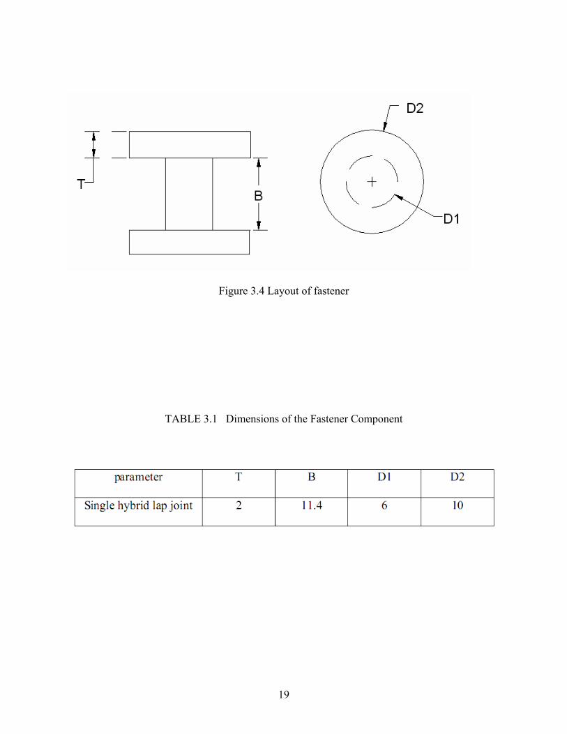
Figure 3.4 Layout of fastener
TABLE 3.1 Dimensions of the Fastener Component
19

Modeling of contact surface between hole and the bolt is done using sliding interface
with a coefficient of friction. A neat fit was considered always between the hole and bolt.
Providing contact surface helps in prevention of elements to penetrate into each other, which also
resist relative surface sliding. The coefficient of friction (μ) is empirical property of contact
materials and contact pressure is (P). Product of these two gives the limiting friction shear stress
value i.e. ‘μP’.
Where, for most common materials μ can be given as, 0.1 ≤ μ ≥ 0.3. A friction coefficient of
0.2 was taken between the hole and bolt. In this thesis, master-slave algorithm has been used to
define contact pairs, in this approach master is a hole and slave is a bolt. The bolt shear load was
determined by adding the nodal forces on the mid-surface of the bolt.
3.3 Boundary and Loading Conditions
As shown in Figure 3.5. In single lap hybrid joint the left edge surface of the upper panel
was constrained in X, Y and Z directions and the right edge surface of the lower panel is left free
to move in X-direction only. Uniform tensile load was applied at the right end of the plate. The
effects of both non-linear material properties and non-linear geometry were included in the
analyses.
20

Figure 3.5 Boundary and loading conditions
3.4 Pre-tension
Circular cross section was defined as pre-tension section which is located at fastener
center which divides it symmetrically as shown in the Figure 3.6. The assembly load across the
pretension section is transmitted by the pre-tension node. The pre-tension node should not be
attached to any of the elements in the model and the coordinates at this point are not significant.
A load concentration of 5 KN is applied in Z-direction at pre-tension node (Figure 3.7.).
21

Figure 3.6 Surface Pre-tension
Figure 3.7 Pre-tension node
22

3.5 Formulation
Components of single lap hybrid joints were meshed in ABAQUS using different
methods in this analysis. The Figure 3.8 shows the typical Finite element meshed model of plates
with out bolts of the lap joints.
The flat panels are meshed in square shape and at the overlapped region and region
around the hole are meshed in circular shape. Fine mesh is used to model the interface between
the hole and the fastener and biased mesh was used at the far ends where, the flat panels don’t
overlap as shown in the Figure 3.10 and Figure 3.9 depicts mesh field around the hole. All the
components (namely, flat panels, adhesive and bolt) of the single lap hybrid joint are meshed
using 3-dimenssional 8- node solid brick elements. Figure 3.11 shows finite element meshed
model of a fastener. Table 3.2 discusses about material properties.
Figure 3.8 Meshed model of plates with holes
23

Figure 3.9 Mesh near the hole
Figure 3.10 Biased mesh at plates far end
24

Figure 3.11 Meshed model
TABLE 3.2 Material Types and their Properties
25

3.6 Validation
The finite element model developed in this study has been validated by comparing the FE
model results for single bolted single lap hybrid joint with experimental results for single bolted
single lap hybrid lap joint. The aim of the experimental program was to measure the load
distribution in the hybrid joint and validate the results obtained from the finite element model
[9].
The joint was fitted with an instrumented bolt which was used to measure the shear load.
The dimensions of the joint were restricted by the design of the instrumented bolt. The mid-
length of the bolt shank must lie in the shear plane of the joint to ensure correct measurement of
the bolt shear load. This placed a restriction on the thickness of the adherends used in the joint.
The laminate adherends were fabricated from the carbon fiber /epoxy unidirectional pre-preg
system HTA/6376 (Hexcel Composites). The bonding surfaces were grit-blasted and degreased
prior to bonding and the joints were cured according to the manufacturer’s specification. A hole
of diameter of 6 mm was machined in the joint using a dagger drill with a backing plate used to
prevent back face delamination. The joint was subject to quasi-static tensile testing which was
conducted using a universal testing machine (Instron 4505) with a 100 KN load cell. The
system was fully computer controlled and allowed for acquisition of load, displacement and
strain data. The tests were run in displacement control at a rate of 0.5 mm/min. Loading was
stopped at sub-critical load levels in order to prevent damage to the instrumented bolt. The load
transferred by the bolt in the hybrid joint was measured using a specially instrumented bolt. The
technique was previously used to measure the bolt load transfer in multi-row lap shear joints.
The bolt was a titanium hi-torque lock bolt which was adapted to include load measurement
instrumentation. The bolt was instrumented with two strain gauge rosettes on each side of the
26

bolt. The strain gauges were located equidistant from the shear plane of the joint. Connection of
the strain gauges in a full Wheatstone bridge eliminated the effect of the axial bolt strains on the
shear strain measurement [9].
The signal from the measurement bolt was calibrated by testing a single-lap bolted joint
manufactured from the same adherend material. The measurement bolt was inserted in the hole
and finger tightened to limit the effects of lateral clamping. Tensile load was applied to the
bolted joint and the signal from the measurement bolt and testing machine load cell recorded.
The procedure was repeated three times in order to obtain an average signal characteristic. The
measurement signal from the bolt was correlated to the load cell reading providing a calibration
curve for the bolt. The curve of bolt load versus total applied load (Figure 3.12) is shown to be
non-linear with the bolt load increasing at a greater rate as the joint is loaded [9].
3.12 Bolt load versus Total applied load
27

28
The load transfer by bolt increases by 18% when the tensile load is increased from 1000N
to 2000N as shown in the Figure 3.12. The difference in load transfer by bolt is 20% when the
tensile load of 3000N is used. There is an increase of 27% when the tensile load is increased
from 3000N to 4000N and the increase is 68% for the tensile load of 5000N. There is an increase
of 74% when the tensile load is increased from 5000N to 6000N.
It can be observed from the plot that there is an increase in tensile load values along X-
direction there is change of load transfer values by bolt on the Y axis followed very closely up to
4000N and after that there is significant difference between experimental and FEA values of load
transfer by bolt as seen in the Figure 3.12.

CHAPTER FOUR
RESULTS
The following chapter gives a detailed overview of the load transfer computed using
finite element model for a single lap bolted/hybrid joint. A parametric study has been carried out
to find the effect of various parameters namely Adherend thickness, Material properties, Bolt
diameter, tensile load and the overlap length, on the load transfer by bolt.
4.1 Load Distribution
In a single lap Hybrid/Bolted joint, the applied tensile load on the joints transfers from
one component to another through either interface friction or through transverse shear force and
it is observed that the eccentricity loading leads to bending in joints (Fig 4.1). For the current
condition failure mode prediction is difficult, due to the bending effects. Load transfer outputs
are computed by the bolt in the lower plate which is near to the tensile load applied edge.
Von-mises stress near holes is shown in Figure 4.2. As the compressive stress between
the bolt and the hole is less, this is a signal that there is a transfer of load at the joints due to
interface friction.
Principal stress distribution in X-direction and Von-mises stress near the hole are shown
in Figures 4.3 and 4.4.
29

Figure 4.1 Deformation under tensile load
Figure 4.2 Von-mises stress distribution in the adherends
30

Figure 4.3 Principle stress distribution
Figure 4.4 Von-mises stress distribution
31

Model matrix with different parameter sets shown in Table 4.1. Model matrix shows
different set of models such as MODEL A, MODEL B, MODEL C, MODEL D, MODEL E,
MODEL F, MODEL G, MODEL H, MODEL I, MODEL J, MODEL K, MODEL M, MODEL N
and MODEL O. Parameters include adherend thicknesses of 1.8mm, 3.6mm, 5.4mm; bolt
diameters of 6mm, 7mm, 8mm; overlap lengths of 40mm, 50mm, 60mm; tensile loads of 1000N,
3000N, 4000N and materials carbon/fiber epoxy, HTA/6376 composites laminate (Hexcel
composites) have been used. These above mentioned models are discussed in detail with
simulations in Appendix A.
Table: 4.1 Model Matrix
Model Material Adherend thickness(mm)
Bolt diameter(mm)
Overlap length(mm)
Tensile load(N)
Model A Carbon/fiber epoxy 1.8 6.0 40.0 1000
Model B HTA/6376 1.8 7.0 40.0 1000
Model C Laminate 1.8 8.0 40.0 1000
Model D Carbon/fiber epoxy 1.8 6.0 40.0 4000
Model E Carbon/fiber epoxy 3.6 7.0 40.0 4000
Model F Carbon/fiber epoxy 5.4 8.0 40.0 4000
Model G Carbon/fiber epoxy 5.4 6.0 40.0 1000
Model H Carbon/fiber epoxy 5.4 7.0 40.0 3000
Model I Carbon/fiber epoxy 5.4 8.0 40.0 4000
Model J Carbon/fiber epoxy 1.8 6.0 50.0 1000
Model K Carbon/fiber epoxy 1.8 7.0 50.0 3000
Model L Carbon/fiber epoxy 1.8 8.0 50.0 4000
Model M Carbon/fiber epoxy 1.8 6.0 40.0 4000
Model N Carbon/fiber epoxy 1.8 7.0 50.0 4000
Model O Carbon/fiber epoxy 1.8 8.0 60.0 4000
32

4.2 Influence of Material Properties
Effects of material properties on load transfer were studied by changing elastic properties
and study was done on three different materials. The detailed material properties of these
materials have been shown in the Table 3.2.
Bolt 1
160
165
170
175
180
185
190
195
200
0 1 2 3
Materials
Load
tran
sfer
(N)
MODEL A
Figure 4.5 Load transfer by bolt 1 for MODEL A
Bolt 1
020406080
100120140160180200
0 1 2 3
Materials
Load
tran
sfer
(N)
MODEL B
Figure 4.6 Load transfer by bolt 1 for MODEL B
33

Bolt 1
0
50
100
150
200
250
300
0 1 2 3
Materials
Load
tran
sfer
(N)
MODEL C
Figure 4.7 Load transfer by bolt 1 for MODEL C
Bolt 2
0
50
100
150
200
250
0 1 2 3
Materials
Load
tran
sfer
(N)
MODEL A
Figure 4.8 Load transfer by bolt 2 for MODEL A
34

Bolt 2
0
2040
60
80100
120
140
160
180
0 1 2 3
Materials
Load
tran
sfer
(N)
MODEL B
Figure 4.9 Load transfer by bolt 2 for MODEL B
Bolt 2
0
50
100
150
200
250
0 1 2 3
Materials
Load
tran
sfer
(N)
MODEL C
Figure 4.10 Load transfer by bolt 2 for MODEL C
35

Bolt 1
0
50
100
150
200
250
300
1 2 3
Materials
Load
tran
sfer
(N)
MODEL AMODEL BMODEL C
Figure 4.11 Load transfer by bolt 1 for different material models
Bolt 2
0
50
100
150
200
250
1 2 3
Materials
Load
tran
sfer
(N)
MODEL AMODEL BMODEL C
Figure 4.12 Load transfer by bolt 1 for different material models.
36

There is a difference of 7% load transfer by Bolt 1 when carbon/fiber epoxy is used over
HTA/6376. The difference is 16% when Laminate (Hexcel composites) is used as shown in the
Figure 4.11.
There is a difference of 6% load transfer by Bolt 2 when carbon/fiber epoxy is used over
HTA/6376. The difference is 12% when Laminate (Hexcel composites) is used as shown in the
Figure 4.12.
However, significant change was observed from the graphs (Figures 4.11 and 4.12) in
transfer of load by bolt along Y direction when the elastic properties of the plates on the X axis
were changed.
4.3 Influence of Tensile Load
The effect of tensile load on the load transfer by bolt is studied by running the finite
element analysis for three values of tensile load.
Loads of 1000N, 3000N and 4000N are being studied. The Figure 4.19 and 4.20
Illustrates the distribution of the load transfer developed by the bolt for different tensile loads
applied to the joint.
37

Bolt 1
0
100
200
300
400
500
600
700
0 1000 2000 3000 4000 5000
Tensile load (N)
Load
tran
sfer
(N)
MODEL G
Figure 4.13 Load transfer by bolt 1 for MODEL G
Bolt 1
0
100
200
300
400
500
600
700
0 1000 2000 3000 4000 5000
Tensile load (N)
Load
tran
sfer
(N)
MODEL H
Figure 4.14 Load transfer by bolt 1 for MODEL H
38

Bolt 1
0
100
200
300
400
500
600
700
800
0 1000 2000 3000 4000 5000
Tensile load (N)
Load
tran
sfer
(N)
MODEL I
Figure 4.15 Load transfer by bolt 1 for MODEL I
Bolt 2
0
100
200
300
400
500
600
0 1000 2000 3000 4000 5000
Tensile load (N)
Load
tran
sfer
(N)
MODEL G
Figure 4.16 Load transfer by bolt 2 for MODEL G
39

Bolt 2
0
100
200
300
400
500
600
700
0 1000 2000 3000 4000 5000
Tensile load (N)
Load
tran
sfer
(N)
MODEL H
Figure 4.17 Load transfer by bolt 2 for MODEL H
Bolt 2
0
100
200
300
400
500
600
700
800
0 1000 2000 3000 4000 5000
Tensile load (N)
Load
tran
sfer
(N)
MODEL I
Figure 4.18 Load transfer by bolt 2 for MODEL I
40

Bolt 1
0100200300400500600700800
1000 3000 4000
Tensile load (N)
Load
tran
sfer
(N)
MODEL GMODEL HMODEL I
Figure 4.19 Load transfer by bolt 1 for different tensile loads.
Bolt 2
0100200300400500600700800
1000 3000 4000
Tensile load (N)
Load
tran
sfer
(N)
MODEL GMODEL HMODEL I
Figure 4.20 Load transfer by bolt 2 for different tensile loads
41

The load transfer by Bolt 1 increases by 65% when the tensile load is increased from
1000N to 3000N as shown in the Figure 4.19. The difference in load transfer by bolt is 25%
when the tensile load of 4000N is used.
The load transfer by bolt 2 also increases with the increase of the tensile load as shown in
the Figure 4.20. There is an increase of 60% when the tensile load is increased from 1000N to
3000N and the increase is 20% for the tensile load of 4000N.
It can be observed from the plots that there is increase in tensile load values along X
direction there is change of load transfer values by bolt on the Y axis as seen in the Figures 4.19
and 4.20.
4.4 Influence of Adherend thickness
The effect of Adherend thickness is studied by running the finite element analysis for
different values of Adherend thicknesses.
Adherend thicknesses of 1.8mm, 3.6mm and 5.4mm are used keeping all the other
parameters constant.
42

Bolt 1
0
100
200
300
400
500
600
700
0 1 2 3 4 5 6
Adherend thickness (mm)
Load
tran
sfer
(N)
MODEL D
Figure 4.21 Load transfer by bolt 1 for MODEL D
Bolt 1
0
100
200
300
400
500
600
700
0 1 2 3 4 5 6
Adherend thickness (mm)
Load
tran
sfer
(N)
MODEL E
Figure 4.22 Load transfer by bolt 1 for MODEL E
43

Bolt 1
0
100
200
300
400
500
600
700
800
0 1 2 3 4 5 6
Adherend thickness (mm)
Load
tran
sfer
(N)
MODEL F
Figure 4.23 Load transfer by bolt 1 for MODEL F
Bolt 1
0
100
200
300
400
500
600
700
0 1 2 3 4 5 6
Adherend thickness (mm)
Load
tran
sfer
(N)
MODEL D
Figure 4.24 Load transfer by bolt 2 for MODEL D
44

Bolt 1
0
100
200
300
400
500
600
700
0 1 2 3 4 5 6
Adherend thickness (mm)
Load
tran
sfer
(N)
MODEL E
Figure 4.25 Load transfer by bolt 2 for MODEL E
Bolt 1
0
100
200
300
400
500
600
700
800
0 1 2 3 4 5 6
Adherend thickness (mm)
Load
tran
sfer
(N)
MODEL F
Figure 4.26 Load transfer by bolt 2 for MODEL F
45
Bolt 1
0100200300400500600700800
1.8 3.6 5.4
Adherend thickness (mm)
Load
tran
sfer
(N)
MODEL DMODEL EMODEL F
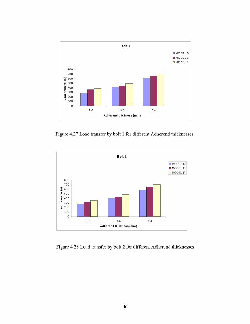
Figure 4.27 Load transfer by bolt 1 for different Adherend thicknesses.
Bolt 2
0100200300400500600700800
1.8 3.6 5.4
Adherend thickness (mm)
Load
tran
sfer
(n)
MODEL DMODEL EMODEL F
Figure 4.28 Load transfer by bolt 2 for different Adherend thicknesses
46

The load transfer by Bolt 1 increases by 48% when the Adherend thickness is increased
from 1.8mm to 3.6mm as shown in the Figure 4.27. The difference in load transfer by bolt is
54% when the Adherend thickness of 5.4mm is used.
The load transfer by bolt 2 also increases with the increase of the Adherend thickness as
shown in the Figure 4.28. There is an increase of 43% when the Adherend thickness is increased
from 1.8mm to 3.6 mm and the increase is 47% for the Adherend thickness of 5.4mm.
As observed in the graphs, it can be concluded that the adherend thickness is directly
proportional to the load transfer.
4.5 Influence of Bolt Diameter
To study the bolt diameter effect on transfer of load by bolt, the hole diameters were
modified as mentioned below in the FEM when the analysis was performed.
Bolt diameters of 6mm, 7mm and 8mm were being used to study the effect of the bolt
diameter.
47

Bolt 1
670
680
690
700
710
720
730
740
750
0 1 2 3 4 5 6 7 8 9
Bolt diameter (mm)
Load
tran
sfer
(N)
MODEL J
Figure 4.29 Load transfer by bolt 1 for MODEL J
Bolt 1
400
410
420
430
440
450
460
470
480
490
0 1 2 3 4 5 6 7 8 9
Bolt diameter (mm)
Load
tran
sfer
(N)
MODEL K
Figure 4.30 Load transfer by bolt 1 for MODEL K
48

Bolt 1
0
50
100
150
200
250
300
350
400
0 1 2 3 4 5 6 7 8 9
Bolt diameter (mm)
Load
tran
sfer
(N)
MODEL L
Figure 4.31 Load transfer by bolt 1 for MODEL L
Bolt 2
660
670
680
690
700
710
720
730
0 1 2 3 4 5 6 7 8 9
Bolt diameter (mm)
Load
tran
sfer
(N)
MODEL J
Figure 4.32 Load transfer by bolt2 for MODEL J
49

Bolt 2
390
400410
420
430440
450
460
470
480
0 1 2 3 4 5 6 7 8 9
Bolt diameter (mm)
Load
tran
sfer
(N)
MODEL K
Figure 4.33 Load transfer by bolt 2 for MODEL K
Bolt 2
0
50
100
150
200
250
300
350
400
0 1 2 3 4 5 6 7 8 9
Bolt diameter (mm)
Load
tran
sfer
(N)
MODEL L
Figure 4.34 Load transfer by bolt 2 for MODEL L
50

Bolt 1
0100200300400500600700800
6 7 8
Bolt diameter (mm)
Load
tran
sfer
(N)
MODEL JMODEL KMODEL L
Figure 4.35 Load transfer by bolt 1 for different Bolt diameters.
Bolt 2
0100200300400500600700800
6 7 8
Bolt diameter (mm)
Load
tran
sfer
(N)
MODEL JMODEL KMODEL L
Figure 4.36 Load transfer by bolt 2 for different Bolt diameters
Increase in bolt diameter (Bolt 1) from 6mm to 7mm shows an increment of 24% in the
load transfer which is shown in Figure 4.35. The difference in load transfer by bolt is 13% when
the bolt diameter of 8mm is used.
51

The load transfer by bolt 2 also increases with the increase of the bolt diameter as shown
in the Figure 4.36. Bolt 2 shows a 22% increment in load transfer when its diameter changed
from 6mm to 7mm and an increment to 11% for 8mm diameter.
It can be observed from the plots that there is increase in bolt diameter values along X
direction there is change of load transfer values by bolt on the Y axis as seen in the Figures 4.35
and 4.36.
4.6 Influence of Overlap length
By changing the overlap length, its effect on the load transfer by the bolt is determined.
Three overlap lengths 40mm, 50mm and 60mm are used to determine the effect on the load
transfer.
Bolt 1
0
100
200
300
400
500
600
700
800
0 10 20 30 40 50 60 70
Overlap length (mm)
Load
tran
sfer
(N)
MODEL M
Figure 4.37 Load transfer by bolt 1 for MODEL M
52

Bolt 1
0
100
200
300
400
500
600
700
0 10 20 30 40 50 60 70
Over lap length (mm)
Load
tran
sfer
(N)
MODEL N
Figure 4.38 Load transfer by bolt 1 for MODEL N
Bolt 1
0
100
200
300
400
500
600
700
800
0 10 20 30 40 50 60 70
Overlap length (mm)
Load
tran
sfer
(N)
MODEL O
Figure 4.39 Load transfer by bolt 1 for MODEL O
53

Bolt 2
0
100
200
300
400
500
600
700
800
0 10 20 30 40 50 60 70
Overlap length (mm)
Load
tran
sfer
(N)
MODEL M
Figure 4.40 Load transfer by bolt 2 for MODEL M
Bolt 2
0
100
200
300
400
500
600
700
0 10 20 30 40 50 60 70
Overlap length (mm)
Load
tran
sfer
(N)
MODEL N
Figure 4.41 Load transfer by bolt 2 for MODEL N
54

Bolt 2
0
100
200
300
400
500
600
0 10 20 30 40 50 60 70
Overlap length (mm)
Load
tran
sfer
(N)
MODEL O
Figure 4.42 Load transfer by bolt 2 for MODEL O
Bolt 1
0100200300400500600700800
40 50 60
Overlap length (mm)
Load
tran
sfer
(N)
MODEL MMODEL NMODEL O
Figure 4.43 Load transfer by bolt 1 for different Overlap lengths.
55

Bolt 2
0100200300400500600700800
40 50 60
Overlap length (mm)
Load
tran
sfer
(N)
MODEL MMODEL NMODEL O
Figure 4.44 Load transfer by bolt 2 for different Overlap lengths.
The load transfer by Bolt 1 decreases by 29% when the Overlap length is increased from
40mm to 50mm as shown in the Figure 4.43. The difference in load transfer by bolt is 34% when
the Overlap length of 60mm is used.
The load transfer by Bolt 2 also decreases with the increase of the Overlap length as
shown in the Figure 4.44. There is a decrease of 27% when the Overlap length is increased from
40mm to 50mm and the decreases is 36% for the Overlap length of 60mm.
This phenomenon is attributed to the fact that with the increase in the over lap length
there is a decrease in the load transfer by bolt.
4.7 Results and Discussions
A difference of 7% load transfer is shown by Bolt 1 when carbon/fiber epoxy is used over
HTA/6376 and 16% difference when Laminate (Hexcel composites) is used as shown in the
Figure 4.11.
56

A difference of 6% load transfer is shown by Bolt 2 when carbon/fiber epoxy is used over
HTA/6376 and the difference is 12% when Laminate is used as shown in the Figure 4.12.
Observation from plots in Figures 4.11 and 4.12 shows a significant change in load
transfer by the bolt along Y-axis with the change of elastic properties of the plates on the X-axis.
Bolt 1 show increase of 48% in load transfer when the Adherend thickness changed from
1.8mm to 3.6mm as shown in the Figure 4.27. The difference in load transfer by bolt is 54%
when the Adherend thickness of 5.4mm is used.
The load transfer by bolt 2 also showed increases with the increase of the Adherend
thickness as shown in the Figure 4.28. 43% increase in load transfer when the Adherend
thickness varied from 1.8mm to 3.6 mm and 47% increase for the Adherend thickness of 5.4mm.
Observed made from the plot that Adherend thickness is directly proportional to the load
transfer.
Increase in tensile load from 1000N to 3000N in Bolt 1, load transfer increased by 65% as
shown in the Figure 4.19. The difference in load transfer by bolt is 25% when the tensile load of
4000N is used.
Load transfer by bolt 2 also increases with the increase of the tensile load as shown in the
Figure 4.20. There is a 60% increase as the tensile load is increased from 1000N to 3000N and
20% increase for tensile load of 4000N.
It can be observed from the plots that as tensile load values along X direction increases
load transfer values changes by bolt on the Y axis as seen in the Figures 4.19 and 4.20.
As the bolt diameter increases from 6mm to 7mm, the load transfer by Bolt 1 increases by
24% as shown in the Figure 4.35. The difference in load transfer by bolt is 13% when the bolt
diameter of 8mm is used.
57

Load transfer by bolt 2 also shows that load transfer is directly proportional to bolt
diameter as shown in the Figure 4.36. Increase of 22% was observed when the bolt diameter is
changed from 6mm to 7mm and an 11% increase for the 8mm bolt diameter.
It can be observed from the plots that there is increase in bolt diameter values along X
direction there is change of load transfer values by bolt on the Y axis as seen in the Figures 4.35
and 4.36.
Load transfer decreased by 29% of Bolt 1, when the Overlap length is changed from
40mm to 50mm as shown in the Figure 4.43. The difference in load transfer by bolt is 34% when
the Overlap length of 60mm is used.
The load transfer by bolt 2 also decreases with the increase of the Overlap length as
shown in the Figure 4.44. There is a decrease of 27% when the Overlap length is increased from
40mm to 50mm and the decreases is 36% for the Overlap length of 60mm.
This phenomenon is attributed to the fact that with the increase in the overlap length there
is a decrease in the load transfer by bolt.
58

CHAPTER FIVE
CONCLUSIONS AND FUTURE WORK
5.1 Conclusions
The main aim of this thesis is to predict the load transfer in the hybrid single lap
joint. A 3D finite element model was developed to investigate effects of different parameters
such as material properties, tensile load, adherend thickness, bolt diameter and overlap length on
the load transfer by bolt. The bolt load results obtained from the finite element analysis for single
bolted single lap hybrid (bonded/bolted) joint have been validated by using an experimental
solution for single bolted single lap hybrid (bonded/bolted) joint. Load transfer values predicted
by the experimental models and the one with finite element method were compared and they are
observed to have a good agreement.
The conclusions of the investigation in this thesis are
(a) The elastic properties of the plate materials have significant effect on the load distribution by
the bolt.
(b) With the increase of the applied tensile load, increase of load transfer by bolt has been
observed.
(c) Increase in the Adherend thickness increases the load transfer by bolt.
(d) Bolt diameter seems to have an impact on the load transfer by bolt, as diameter increases,
transfer of load by bolt increase.
(e) The load transfer developed is affected by the overlap length, as the overlap length increases
there is a decrease in the load transfer values.
59

5.2 Future Work
A parametric study is done to investigate the effects of various parameters such as
material properties, tensile load, adherend thickness, bolt diameter and overlap length on load
transfer by bolt in a single lap hybrid joint by using ABAQUS 6.4 version. In addition to this
there is a need to study of;
(a) Load transfer in multi fastened single and double lap hybrid (bonded/bolted) shear and
tensile joints.
(b) Stress distribution around the hole in multi fastened single and double lap hybrid
(bonded/bolted) shear and tensile joints.
60

REFERENCES
61

LIST OF REFERENCES
[1] ABAQUS/Standard Users Manual, Version 6.4, 2006.
[2] Cope, D.A., and Lacy, T.E., “Stress Intensity Determination in Lap Joints with Mechanical Fasteners,” 41st AIAA/ASME/ASCEIAHS/ASC Structures, Structural Dynamics, and Material conference and Exhibit, pp. 1-10, 2000.
[3] Drabek, T., and Bohm, H.J., “Micromechanical Finite Element Analysis of Metal Matrix
Composites using Nonlocal Ductile Failure Models,” Computational Materials Science, Vol. 37, pp. 29-36, 2006.
[4] Fukuoka, T., and Takaki, T., “Mechanical Behavior of Bolted Joint in Various clamping
Configurations,” Journal of Pressure Vessel Technology, Vol. 120, 1998, pp226-231. [5] Katepalli, N.B., “Parametric study of Stress Concentration in Bolted lap joints
between Particulate metal matrix Composite materials”. Masters Thesis, Wichita State University, 2006.
[6] Lehnhoff, T.F., and Wistehuff, W.E., “Nonlinear Effects on the Stresses and
Deformations of Bolted Joints,” Journal of Pressure Vessel Technology, Vol. 118, pp. 54-58, 1996.
[7] Menzemer, C.C., Fei, L., and Srivatsan, T.S., “Design Criteria for Bolted Connection
Elements in Aluminum Alloy 6601,” Journal of Mechanical Design, Vol. 121, pp. 348-358, 1999.
[8] Riccio, A., and Marciano, L., “Effects of Geometrical and Material Features on Damage
Onset and Propagation in Single-lap Bolted Composite Joint sunder Tensile Load: Part I–Experimental Studies,” Journal of Composite Materials, Vol. 39, PP 2071, 2005.
[9] Kelly, G., Load transfer in hybrid (bonded/bolted) composite single-lap joints.
Composite Structures, Volume 69, Issue 1, Pages 35-43, available online 2 June 2004. [10] Ananthram K.S., “Finite element and Analytical Models for Load transfer calculations in
Mechanically Fastened Aluminum/Composite Hybrid joints” Masters Thesis, Wichita State University, 2005.
[11] Lehnhoff, T.F., and Bunyard, B.A., “Effect of bolt threads on the Stiffness of Bolted
Joints,” Journal of Pressure Vessel Technology, Vol. 381, pp. 141-146, 1998. [12] Eric, P., Marc, S., Jacques, H., Frédéric, L., “Analytical two-dimensional model of a
hybrid (bolted/bonded) single-lap joint,” Journal of Aircraft, v 44, n 2, p 573-582, March/April 2007.
62

63
[13] Joint Design, www.ellsworth.com, cited 2006. [14] Rodriguez, D., Carlin, J., and Rey, R., “Stress Concentration Study in Bolted joints by
Finite Element Modeling: Experimental and Analytical Approach,” European Conference of Spacecraft Structures, Materials and Mechanical Testing, pp. 2-6, 2005.
[15] Meka, U.S., “Finite Element and Analytical Models for Load transfer Calculations in
Structures utilizing Metal and Composites with Large CTE differences” Master’s Thesis, Wichita State University, 2007.
[16] Weeton, J.W., Peters, D.M., and Thomas, K.L., “Engineers Guide To Composite
Materials,” American Society for Metals, 1987. [17] Hibbitt, H.B., Nagtegaal, J.C., “Computer Process for Prescribing an Assembly Load
to Provide Pre-tensioning Simulation in the Design Analysis of Load Bearing Structures”. January 1997.
[18] Snyder, B.D., Burns, J.G., and Venkayya, V.B., “Composite Bolted Joints Analysis
Programs,” Proceedings of the AIAA/ASME/ ASCE/AHS/ASC 29th Structures, Structural Dynamics and Materials Conference, AIAA, Washington, D. C., April 2005.
[19] Technical Information, Bolted joints, handbook, 2000. [20] Gerbert, G., and Bastedt, H., “Centrically Loaded Bolted Joints” Journal of Mechanical Design, Vol. 115, pp 701-705, 1993. [21] Bickford, J.H., “An Introduction to the Design and Behavior of Bolted Joints”, Third Edition, Revised and Expanded, 2003.

APPENDIX A MODEL A Description and Results
Model Model A
Adherend Thickness 1.8 mm
Bolt Diameter 6mm
Tensile Load 1000 N
Overlap Length 40 mm
Material Carbon/fiber epoxy
Load transfer by bolt1 164 N
Load transfer by bolt2 160 N
64

MODEL B Description and Results
Model Model B
Adherend Thickness 1.8 mm
Bolt Diameter 7mm
Tensile Load 1000 N
Overlap Length 40 mm
Material HTA/6376
Load transfer by bolt1 180 N
Load transfer by bolt2 160 N
65

MODEL C Description and Results
Model Model C
Adherend Thickness 1.8 mm
Bolt Diameter 8mm
Tensile Load 1000 N
Overlap Length 40 mm
Material Laminate (Hexcel composites)
Load transfer by bolt1 190 N
Load transfer by bolt2 180 N
66

MODEL D Description and Results
Model Model D
Adherend Thickness 1.8 mm
Bolt Diameter 6mm
Tensile Load 1000 N
Overlap Length 40 mm
Material Carbon/fiber epoxy
Load transfer by bolt1 164 N
Load transfer by bolt2 160 N
67

MODEL E Description and Results
Model Model E
Adherend Thickness 3.6 mm
Bolt Diameter 7mm
Tensile Load 1000 N
Overlap Length 40 mm
Material Carbon/fiber epoxy
Load transfer by bolt1 270 N
Load transfer by bolt2 250 N
68

MODEL F Description and Results
Model Model F
Adherend Thickness 5.4 mm
Bolt Diameter 8mm
Tensile Load 1000 N
Overlap Length 40 mm
Material Carbon/fiber epoxy
Load transfer by bolt1 320 N
Load transfer by bolt2 310 N
69

MODEL G Description and Results
Model Model G
Adherend Thickness 1.8 mm
Bolt Diameter 6mm
Tensile Load 1000 N
Overlap Length 40 mm
Material Carbon/fiber epoxy
Load transfer by bolt1 164 N
Load transfer by bolt2 160 N
70

MODEL H Description and Results
Model Model H
Adherend Thickness 1.8 mm
Bolt Diameter 7mm
Tensile Load 3000 N
Overlap Length 40 mm
Material Carbon/fiber epoxy
Load transfer by bolt1 500 N
Load transfer by bolt2 480 N
71

MODEL I Description and Results
Model Model I
Adherend Thickness 1.8 mm
Bolt Diameter 8mm
Tensile Load 4000 N
Overlap Length 40 mm
Material Carbon/fiber epoxy
Load transfer by bolt1 700 N
Load transfer by bolt2 680 N
72

MODEL J Description and Results
Model Model J
Adherend Thickness 1.8 mm
Bolt Diameter 6mm
Tensile Load 1000 N
Overlap Length 40 mm
Material Carbon/fiber epoxy
Load transfer by bolt1 164 N
Load transfer by bolt2 160 N
73

MODEL K Description and Results
Model Model K
Adherend Thickness 3.6 mm
Bolt Diameter 7mm
Tensile Load 1000 N
Overlap Length 40 mm
Material Carbon/fiber epoxy
Load transfer by bolt1 270 N
Load transfer by bolt2 250 N
74

MODEL L Description and Results
Model Model L
Adherend Thickness 5.4 mm
Bolt Diameter 8mm
Tensile Load 1000 N
Overlap Length 40 mm
Material Carbon/fiber epoxy
Load transfer by bolt1 720 N
Load transfer by bolt2 700 N
75

MODEL M Description and Results
Model Model M
Adherend Thickness 1.8 mm
Bolt Diameter 6mm
Tensile Load 4000 N
Overlap Length 40 mm
Material Carbon/fiber epoxy
Load transfer by bolt1 320 N
Load transfer by bolt2 310 N
76

MODEL N Description and Results
Model Model N
Adherend Thickness 1.8 mm
Bolt Diameter 7mm
Tensile Load 4000 N
Overlap Length 50 mm
Material Carbon/fiber epoxy
Load transfer by bolt1 520 N
Load transfer by bolt2 500 N
77

MODEL O Description and Results
Model Model O
Adherend Thickness 1.8 mm
Bolt Diameter 8mm
Tensile Load 4000 N
Overlap Length 60 mm
Material Carbon/fiber epoxy
Load transfer by bolt1 340 N
Load transfer by bolt2 320 N
78

APPENDIX B Heading Job name: bd81 Model name: bd814 Preprint, echo=NO, model=NO, history=NO, contact=NO * PARTS * Part, name=BOLT-1 End Part Part, name=BOLT-2 End Part Part, name=PLATE1-1 End Part * ASSEMBLY * Assembly, name=Assembly * Instance, name=PLATE1-1, part=PLATE1-1 Node 1, 100., 0., 0. 2, 100., 1.8, 0. 3, 110., 1.8, 0. 4, 110., 0., 0. 5, 100., 0., 6.5 . . . . . *Element, type=C3D8I 1, 1481, 1482, 4809, 4802, 155, 156, 1461, 1460 2, 1482, 1483, 4810, 4809, 156, 157, 1462, 1461 3, 1483, 1484, 4811, 4810, 157, 158, 1463, 1462 4, 1484, 162, 1472, 4811, 158, 1, 159, 1463 5, 4802, 4809, 4799, 4798, 1460, 1461, 1465, 1464 . . . . . *Elset, elset=_I1, internal 1, 2, 3, 4, 5, 6, 7, 8, 9, 10, 11, 12, 13, 14, 15, 16
79
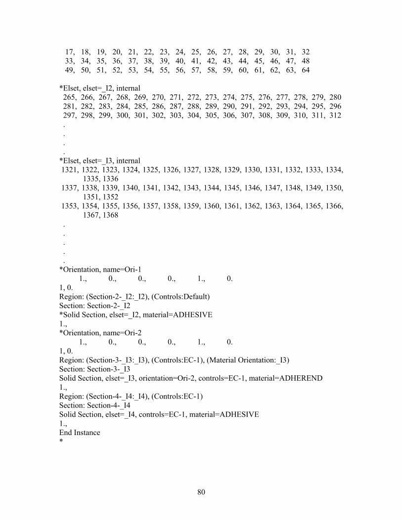
17, 18, 19, 20, 21, 22, 23, 24, 25, 26, 27, 28, 29, 30, 31, 32 33, 34, 35, 36, 37, 38, 39, 40, 41, 42, 43, 44, 45, 46, 47, 48 49, 50, 51, 52, 53, 54, 55, 56, 57, 58, 59, 60, 61, 62, 63, 64 *Elset, elset=_I2, internal 265, 266, 267, 268, 269, 270, 271, 272, 273, 274, 275, 276, 277, 278, 279, 280 281, 282, 283, 284, 285, 286, 287, 288, 289, 290, 291, 292, 293, 294, 295, 296 297, 298, 299, 300, 301, 302, 303, 304, 305, 306, 307, 308, 309, 310, 311, 312 . . . . *Elset, elset=_I3, internal 1321, 1322, 1323, 1324, 1325, 1326, 1327, 1328, 1329, 1330, 1331, 1332, 1333, 1334,
1335, 1336 1337, 1338, 1339, 1340, 1341, 1342, 1343, 1344, 1345, 1346, 1347, 1348, 1349, 1350,
1351, 1352 1353, 1354, 1355, 1356, 1357, 1358, 1359, 1360, 1361, 1362, 1363, 1364, 1365, 1366,
1367, 1368 . . . . . *Orientation, name=Ori-1 1., 0., 0., 0., 1., 0. 1, 0. Region: (Section-2-_I2:_I2), (Controls:Default) Section: Section-2-_I2 *Solid Section, elset=_I2, material=ADHESIVE 1., *Orientation, name=Ori-2 1., 0., 0., 0., 1., 0. 1, 0. Region: (Section-3-_I3:_I3), (Controls:EC-1), (Material Orientation:_I3) Section: Section-3-_I3 Solid Section, elset=_I3, orientation=Ori-2, controls=EC-1, material=ADHEREND 1., Region: (Section-4-_I4:_I4), (Controls:EC-1) Section: Section-4-_I4 Solid Section, elset=_I4, controls=EC-1, material=ADHESIVE 1., End Instance *
80
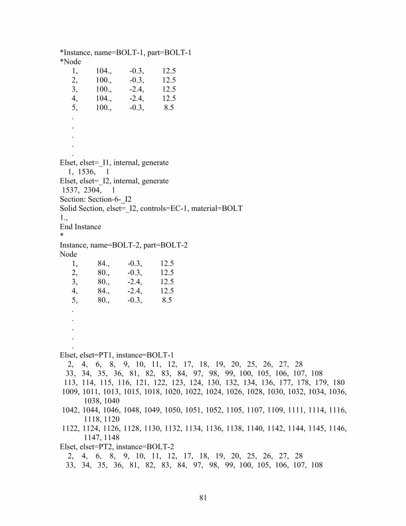
*Instance, name=BOLT-1, part=BOLT-1 *Node 1, 104., -0.3, 12.5 2, 100., -0.3, 12.5 3, 100., -2.4, 12.5 4, 104., -2.4, 12.5 5, 100., -0.3, 8.5 . . . . . Elset, elset=_I1, internal, generate 1, 1536, 1 Elset, elset=_I2, internal, generate 1537, 2304, 1 Section: Section-6-_I2 Solid Section, elset=_I2, controls=EC-1, material=BOLT 1., End Instance * Instance, name=BOLT-2, part=BOLT-2 Node 1, 84., -0.3, 12.5 2, 80., -0.3, 12.5 3, 80., -2.4, 12.5 4, 84., -2.4, 12.5 5, 80., -0.3, 8.5 . . . . . Elset, elset=PT1, instance=BOLT-1 2, 4, 6, 8, 9, 10, 11, 12, 17, 18, 19, 20, 25, 26, 27, 28 33, 34, 35, 36, 81, 82, 83, 84, 97, 98, 99, 100, 105, 106, 107, 108 113, 114, 115, 116, 121, 122, 123, 124, 130, 132, 134, 136, 177, 178, 179, 180 1009, 1011, 1013, 1015, 1018, 1020, 1022, 1024, 1026, 1028, 1030, 1032, 1034, 1036,
1038, 1040 1042, 1044, 1046, 1048, 1049, 1050, 1051, 1052, 1105, 1107, 1109, 1111, 1114, 1116,
1118, 1120 1122, 1124, 1126, 1128, 1130, 1132, 1134, 1136, 1138, 1140, 1142, 1144, 1145, 1146,
1147, 1148 Elset, elset=PT2, instance=BOLT-2 2, 4, 6, 8, 9, 10, 11, 12, 17, 18, 19, 20, 25, 26, 27, 28 33, 34, 35, 36, 81, 82, 83, 84, 97, 98, 99, 100, 105, 106, 107, 108
81

113, 114, 115, 116, 121, 122, 123, 124, 130, 132, 134, 136, 177, 178, 179, 180 1009, 1011, 1013, 1015, 1018, 1020, 1022, 1024, 1026, 1028, 1030, 1032, 1034, 1036,
1038, 1040 1042, 1044, 1046, 1048, 1049, 1050, 1051, 1052, 1105, 1107, 1109, 1111, 1114, 1116,
1118, 1120 1122, 1124, 1126, 1128, 1130, 1132, 1134, 1136, 1138, 1140, 1142, 1144, 1145, 1146,
1147, 1148 *Elset, elset=_PT1_S2, internal, instance=BOLT-1 81, 82, 83, 84, 177, 178, 179, 180, 1049, 1050, 1051, 1052, 1145, 1146, 1147,
1148 *Elset, elset=_PT2_S2, internal, instance=BOLT-2 81, 82, 83, 84, 177, 178, 179, 180, 1049, 1050, 1051, 1052, 1145, 1146, 1147,
1148 *Elset, elset=_BOLT1DOWN_S4, internal, instance=BOLT-1 73, 74, 75, 76, 77, 78, 79, 80, 137, 138, 139, 140, 141, 142, 143, 144 961, 962, 963, 964, 965, 966, 967, 968, 1009, 1010, 1011, 1012, 1013, 1014, 1015,
1016 1049, 1050, 1051, 1052, 1053, 1054, 1055, 1056, 1057, 1058, 1059, 1060, 1061, 1062,
1063, 1064 1105, 1106, 1107, 1108, 1109, 1110, 1111, 1112, 1145, 1146, 1147, 1148, 1149, 1150,
1151, 1152 *Elset, elset=_BOLT1DOWN_S3, internal, instance=BOLT-1 1, 2, 3, 4, 5, 6, 7, 8, 81, 82, 83, 84, 85, 86, 87, 88 129, 130, 131, 132, 133, 134, 135, 136, 177, 178, 179, 180, 181, 182, 183, 184 185, 186, 187, 188, 189, 190, 191, 192, 1001, 1002, 1003, 1004, 1005, 1006, 1007,
1008 1097, 1098, 1099, 1100, 1101, 1102, 1103, 1104 *Elset, elset=_BOLT1DOWN_S2, internal, instance=BOLT-1 89, 90, 91, 92, 93, 94, 95, 96, 1537, 1538, 1539, 1540, 1541, 1542, 1543, 1544 1545, 1546, 1547, 1548, 1549, 1550, 1551, 1552, 1553, 1554, 1555, 1556, 1557, 1558,
1559, 1560 *Elset, elset=_BOLT1DOWN_S1, internal, instance=BOLT-1 1705, 1706, 1707, 1708, 1709, 1710, 1711, 1712, 1713, 1714, 1715, 1716, 1717, 1718,
1719, 1720 1721, 1722, 1723, 1724, 1725, 1726, 1727, 1728, 2185, 2186, 2187, 2188, 2189, 2190,
2191, 2192 2193, 2194, 2195, 2196, 2197, 2198, 2199, 2200, 2201, 2202, 2203, 2204, 2205, 2206,
2207, 2208 2281, 2282, 2283, 2284, 2285, 2286, 2287, 2288, 2289, 2290, 2291, 2292, 2293, 2294,
2295, 2296 2297, 2298, 2299, 2300, 2301, 2302, 2303, 2304 *Elset, elset=_BOLT1TOP_S3, internal, instance=BOLT-1 321, 322, 323, 324, 325, 326, 327, 328, 369, 370, 371, 372, 373, 374, 375, 376 377, 378, 379, 380, 381, 382, 383, 384, 1153, 1154, 1155, 1156, 1157, 1158, 1159,
1160
82

1281, 1282, 1283, 1284, 1285, 1286, 1287, 1288, 1297, 1298, 1299, 1300, 1301, 1302, 1303, 1304
1337, 1338, 1339, 1340, 1341, 1342, 1343, 1344 *Elset, elset=_BOLT1TOP_S4, internal, instance=BOLT-1 329, 330, 331, 332, 333, 334, 335, 336, 1161, 1162, 1163, 1164, 1165, 1166, 1167,
1168 1289, 1290, 1291, 1292, 1293, 1294, 1295, 1296 *Elset, elset=_BOLT1TOP_S2, internal, instance=BOLT-1 193, 194, 195, 196, 197, 198, 199, 200, 201, 202, 203, 204, 205, 206, 207, 208 209, 210, 211, 212, 213, 214, 215, 216, 217, 218, 219, 220, 221, 222, 223, 224 1201, 1202, 1203, 1204, 1205, 1206, 1207, 1208, 1209, 1210, 1211, 1212, 1213, 1214,
1215, 1216 *Elset, elset=_BOLT1TOP_S1, internal, instance=BOLT-1 1801, 1802, 1803, 1804, 1805, 1806, 1807, 1808, 1809, 1810, 1811, 1812, 1813, 1814,
1815, 1816 1817, 1818, 1819, 1820, 1821, 1822, 1823, 1824, 1897, 1898, 1899, 1900, 1901, 1902,
1903, 1904 1905, 1906, 1907, 1908, 1909, 1910, 1911, 1912, 1913, 1914, 1915, 1916, 1917, 1918,
1919, 1920 1993, 1994, 1995, 1996, 1997, 1998, 1999, 2000, 2001, 2002, 2003, 2004, 2005, 2006,
2007, 2008 2009, 2010, 2011, 2012, 2013, 2014, 2015, 2016, 2089, 2090, 2091, 2092, 2093, 2094,
2095, 2096 2097, 2098, 2099, 2100, 2101, 2102, 2103, 2104, 2105, 2106, 2107, 2108, 2109, 2110,
2111, 2112 *Elset, elset=_BOLT2DOWN_S4, internal, instance=BOLT-2 73, 74, 75, 76, 77, 78, 79, 80, 137, 138, 139, 140, 141, 142, 143, 144 961, 962, 963, 964, 965, 966, 967, 968, 1009, 1010, 1011, 1012, 1013, 1014, 1015,
1016 1049, 1050, 1051, 1052, 1053, 1054, 1055, 1056, 1057, 1058, 1059, 1060, 1061, 1062,
1063, 1064 1105, 1106, 1107, 1108, 1109, 1110, 1111, 1112, 1145, 1146, 1147, 1148, 1149, 1150,
1151, 1152 *Elset, elset=_BOLT2DOWN_S3, internal, instance=BOLT-2 1, 2, 3, 4, 5, 6, 7, 8, 81, 82, 83, 84, 85, 86, 87, 88 129, 130, 131, 132, 133, 134, 135, 136, 177, 178, 179, 180, 181, 182, 183, 184 185, 186, 187, 188, 189, 190, 191, 192, 1001, 1002, 1003, 1004, 1005, 1006, 1007,
1008 1097, 1098, 1099, 1100, 1101, 1102, 1103, 1104 *Elset, elset=_BOLT2DOWN_S2, internal, instance=BOLT-2 89, 90, 91, 92, 93, 94, 95, 96, 1537, 1538, 1539, 1540, 1541, 1542, 1543, 1544 1545, 1546, 1547, 1548, 1549, 1550, 1551, 1552, 1553, 1554, 1555, 1556, 1557, 1558,
1559, 1560 *Elset, elset=_BOLT2DOWN_S1, internal, instance=BOLT-2 1705, 1706, 1707, 1708, 1709, 1710, 1711, 1712, 1713, 1714, 1715, 1716, 1717, 1718,
1719, 1720
83

1721, 1722, 1723, 1724, 1725, 1726, 1727, 1728, 2185, 2186, 2187, 2188, 2189, 2190, 2191, 2192
2193, 2194, 2195, 2196, 2197, 2198, 2199, 2200, 2201, 2202, 2203, 2204, 2205, 2206, 2207, 2208
2281, 2282, 2283, 2284, 2285, 2286, 2287, 2288, 2289, 2290, 2291, 2292, 2293, 2294, 2295, 2296
2297, 2298, 2299, 2300, 2301, 2302, 2303, 2304 *Elset, elset=_BOLT2TOP_S3, internal, instance=BOLT-2 321, 322, 323, 324, 325, 326, 327, 328, 369, 370, 371, 372, 373, 374, 375, 376 377, 378, 379, 380, 381, 382, 383, 384, 1153, 1154, 1155, 1156, 1157, 1158, 1159,
1160 1281, 1282, 1283, 1284, 1285, 1286, 1287, 1288, 1297, 1298, 1299, 1300, 1301, 1302,
1303, 1304 1337, 1338, 1339, 1340, 1341, 1342, 1343, 1344 *Elset, elset=_BOLT2TOP_S4, internal, instance=BOLT-2 329, 330, 331, 332, 333, 334, 335, 336, 1161, 1162, 1163, 1164, 1165, 1166, 1167,
1168 1289, 1290, 1291, 1292, 1293, 1294, 1295, 1296 *Elset, elset=_BOLT2TOP_S2, internal, instance=BOLT-2 193, 194, 195, 196, 197, 198, 199, 200, 201, 202, 203, 204, 205, 206, 207, 208 209, 210, 211, 212, 213, 214, 215, 216, 217, 218, 219, 220, 221, 222, 223, 224 1201, 1202, 1203, 1204, 1205, 1206, 1207, 1208, 1209, 1210, 1211, 1212, 1213, 1214,
1215, 1216 *Elset, elset=_BOLT2TOP_S1, internal, instance=BOLT-2 1801, 1802, 1803, 1804, 1805, 1806, 1807, 1808, 1809, 1810, 1811, 1812, 1813, 1814,
1815, 1816 1817, 1818, 1819, 1820, 1821, 1822, 1823, 1824, 1897, 1898, 1899, 1900, 1901, 1902,
1903, 1904 1905, 1906, 1907, 1908, 1909, 1910, 1911, 1912, 1913, 1914, 1915, 1916, 1917, 1918,
1919, 1920 1993, 1994, 1995, 1996, 1997, 1998, 1999, 2000, 2001, 2002, 2003, 2004, 2005, 2006,
2007, 2008 2009, 2010, 2011, 2012, 2013, 2014, 2015, 2016, 2089, 2090, 2091, 2092, 2093, 2094,
2095, 2096 2097, 2098, 2099, 2100, 2101, 2102, 2103, 2104, 2105, 2106, 2107, 2108, 2109, 2110,
2111, 2112 *Elset, elset=_HOLE1DOWN_S6, internal, instance=PLATE1-1 4499, 4502, 4505, 4508, 4511, 4514, 4517, 4520, 4523, 4526, 4529, 4532, 4535, 4538,
4541, 4544 4547, 4550, 4553, 4556, 4559, 4562, 4565, 4568, 4571, 4574, 4577, 4580, 4583, 4586,
4589, 4592 4889, 4893, 4897, 4901, 4905, 4909, 4913, 4917, 4921, 4925, 4929, 4933, 4937, 4941,
4945, 4949 4953, 4957, 4961, 4965, 4969, 4973, 4977, 4981, 4985, 4989, 4993, 4997, 5001, 5005,
5009, 5013
84

5017, 5021, 5025, 5029, 5033, 5037, 5041, 5045, 5049, 5053, 5057, 5061, 5065, 5069, 5073, 5077
*Elset, elset=_HOLE1DOWN_S2, internal, instance=PLATE1-1 4403, 4404, 4405, 4406, 4407, 4408, 4409, 4410, 4411, 4412, 4413, 4414, 4415, 4416,
4417, 4418 4419, 4420, 4421, 4422, 4423, 4424, 4425, 4426, 4427, 4428, 4429, 4430, 4431, 4432,
4433, 4434 4889, 4890, 4891, 4892, 4893, 4894, 4895, 4896, 4897, 4898, 4899, 4900, 4901, 4902,
4903, 4904 4905, 4906, 4907, 4908, 4909, 4910, 4911, 4912, 4913, 4914, 4915, 4916, 4917, 4918,
4919, 4920 *Elset, elset=_HOLE1DOWN_S4, internal, instance=PLATE1-1, generate 4406, 4498, 4 *Elset, elset=_HOLE1DOWN_S1, internal, instance=PLATE1-1, generate 4571, 4594, 1 *Elset, elset=_HOLE1DOWN_S5, internal, instance=PLATE1-1 4993, 4994, 4995, 4996, 5005, 5006, 5007, 5008, 5017, 5018, 5019, 5020, 5029, 5030,
5031, 5032 5041, 5042, 5043, 5044, 5053, 5054, 5055, 5056, 5065, 5066, 5067, 5068, 5077, 5078,
5079, 5080 *Elset, elset=_HOLE1TOP_S6, internal, instance=PLATE1-1, generate 3901, 3994, 3 *Elset, elset=_HOLE1TOP_S2, internal, instance=PLATE1-1 3901, 3902, 3903, 3904, 3905, 3906, 3907, 3908, 3909, 3910, 3911, 3912, 3913, 3914,
3915, 3916 3917, 3918, 3919, 3920, 3921, 3922, 3923, 3924, 4211, 4212, 4213, 4214, 4215, 4216,
4217, 4218 4219, 4220, 4221, 4222, 4223, 4224, 4225, 4226, 4227, 4228, 4229, 4230, 4231, 4232,
4233, 4234 *Elset, elset=_HOLE1TOP_S4, internal, instance=PLATE1-1 3808, 3812, 3816, 3820, 3824, 3828, 3832, 3836, 3840, 3844, 3848, 3852, 3856, 3860,
3864, 3868 3872, 3876, 3880, 3884, 3888, 3892, 3896, 3900, 4118, 4122, 4126, 4130, 4134, 4138,
4142, 4146 4150, 4154, 4158, 4162, 4166, 4170, 4174, 4178, 4182, 4186, 4190, 4194, 4198, 4202,
4206, 4210 4213, 4216, 4219, 4222, 4225, 4228, 4231, 4234, 4237, 4240, 4243, 4246, 4249, 4252,
4255, 4258 4261, 4264, 4267, 4270, 4273, 4276, 4279, 4282, 4285, 4288, 4291, 4294, 4297, 4300,
4303, 4306 *Elset, elset=_HOLE1TOP_S5, internal, instance=PLATE1-1 3813, 3814, 3815, 3816, 3825, 3826, 3827, 3828, 3837, 3838, 3839, 3840, 3849, 3850,
3851, 3852 3861, 3862, 3863, 3864, 3873, 3874, 3875, 3876, 3885, 3886, 3887, 3888, 3897, 3898,
3899, 3900
85

4123, 4124, 4125, 4126, 4135, 4136, 4137, 4138, 4147, 4148, 4149, 4150, 4159, 4160, 4161, 4162
4171, 4172, 4173, 4174, 4183, 4184, 4185, 4186, 4195, 4196, 4197, 4198, 4207, 4208, 4209, 4210
*Elset, elset=_HOLE2TOP_S1, internal, instance=PLATE1-1 3429, 3430, 3431, 3432, 3433, 3434, 3435, 3436, 3437, 3438, 3439, 3440, 3441, 3442,
3443, 3444 3445, 3446, 3447, 3448, 3449, 3450, 3451, 3452, 4667, 4668, 4669, 4670, 4671, 4672,
4673, 4674 4675, 4676, 4677, 4678, 4679, 4680, 4681, 4682, 4683, 4684, 4685, 4686, 4687, 4688,
4689, 4690 *Elset, elset=_HOLE2TOP_S6, internal, instance=PLATE1-1 3453, 3457, 3461, 3465, 3469, 3473, 3477, 3481, 3485, 3489, 3493, 3497, 3501, 3505,
3509, 3513 3517, 3521, 3525, 3529, 3533, 3537, 3541, 3545, 3549, 3553, 3557, 3561, 3565, 3569,
3573, 3577 3581, 3585, 3589, 3593, 3597, 3601, 3605, 3609, 3613, 3617, 3621, 3625, 3629, 3633,
3637, 3641 4595, 4598, 4601, 4604, 4607, 4610, 4613, 4616, 4619, 4622, 4625, 4628, 4631, 4634,
4637, 4640 4643, 4646, 4649, 4652, 4655, 4658, 4661, 4664, 4667, 4670, 4673, 4676, 4679, 4682,
4685, 4688 *Elset, elset=_HOLE2TOP_S4, internal, instance=PLATE1-1, generate 3359, 3452, 3 *Elset, elset=_HOLE2TOP_S5, internal, instance=PLATE1-1 3461, 3462, 3463, 3464, 3473, 3474, 3475, 3476, 3485, 3486, 3487, 3488, 3497, 3498,
3499, 3500 3509, 3510, 3511, 3512, 3521, 3522, 3523, 3524, 3533, 3534, 3535, 3536, 3545, 3546,
3547, 3548 3557, 3558, 3559, 3560, 3569, 3570, 3571, 3572, 3581, 3582, 3583, 3584, 3593, 3594,
3595, 3596 3605, 3606, 3607, 3608, 3617, 3618, 3619, 3620, 3629, 3630, 3631, 3632, 3641, 3642,
3643, 3644 *Elset, elset=_HOLE2DOWN_S6, internal, instance=PLATE1-1 2895, 2899, 2903, 2907, 2911, 2915, 2919, 2923, 2927, 2931, 2935, 2939, 2943, 2947,
2951, 2955 2959, 2963, 2967, 2971, 2975, 2979, 2983, 2987, 2991, 2994, 2997, 3000, 3003, 3006,
3009, 3012 3015, 3018, 3021, 3024, 3027, 3030, 3033, 3036, 3039, 3042, 3045, 3048, 3051, 3054,
3057, 3060 3063, 3066, 3069, 3072, 3075, 3078, 3081, 3084, 3135, 3139, 3143, 3147, 3151, 3155,
3159, 3163 3167, 3171, 3175, 3179, 3183, 3187, 3191, 3195, 3199, 3203, 3207, 3211, 3215, 3219,
3223, 3227 *Elset, elset=_HOLE2DOWN_S4, internal, instance=PLATE1-1, generate 2643, 2736, 3
86

*Elset, elset=_HOLE2DOWN_S1, internal, instance=PLATE1-1 2713, 2714, 2715, 2716, 2717, 2718, 2719, 2720, 2721, 2722, 2723, 2724, 2725, 2726,
2727, 2728 2729, 2730, 2731, 2732, 2733, 2734, 2735, 2736, 3063, 3064, 3065, 3066, 3067, 3068,
3069, 3070 3071, 3072, 3073, 3074, 3075, 3076, 3077, 3078, 3079, 3080, 3081, 3082, 3083, 3084,
3085, 3086 *Elset, elset=_HOLE2DOWN_S5, internal, instance=PLATE1-1 2903, 2904, 2905, 2906, 2915, 2916, 2917, 2918, 2927, 2928, 2929, 2930, 2939, 2940,
2941, 2942 2951, 2952, 2953, 2954, 2963, 2964, 2965, 2966, 2975, 2976, 2977, 2978, 2987, 2988,
2989, 2990 3143, 3144, 3145, 3146, 3155, 3156, 3157, 3158, 3167, 3168, 3169, 3170, 3179, 3180,
3181, 3182 3191, 3192, 3193, 3194, 3203, 3204, 3205, 3206, 3215, 3216, 3217, 3218, 3227, 3228,
3229, 3230 *Elset, elset=_PT1_S3, internal, instance=BOLT-1 9, 10, 11, 12, 17, 18, 19, 20, 25, 26, 27, 28, 33, 34, 35, 36 97, 98, 99, 100, 105, 106, 107, 108, 113, 114, 115, 116, 121, 122, 123, 124 1009, 1011, 1013, 1015, 1105, 1107, 1109, 1111 *Elset, elset=_PT2_S3, internal, instance=BOLT-2 9, 10, 11, 12, 17, 18, 19, 20, 25, 26, 27, 28, 33, 34, 35, 36 97, 98, 99, 100, 105, 106, 107, 108, 113, 114, 115, 116, 121, 122, 123, 124 1009, 1011, 1013, 1015, 1105, 1107, 1109, 1111 *Nset, nset=_PickedSet94, internal, instance=PLATE1-1 143, 144, 145, 146, 147, 148, 1311, 1312, 1313, 1314, 1333, 1334, 1335, 1336, 1346,
1347 1348, 1349, 1350, 1351, 1352, 1353, 1354, 1355, 1365, 1366, 1367, 1368, 1378, 1379,
1380, 4426 4427, 4428, 4429, 4430, 4431, 4432, 4433, 4434, 4435, 4436, 4437, 4510, 4511, 4512,
4513, 4514 4515, 4516, 4517, 4518, 4519, 4520, 4521 *Nset, nset=_PickedSet95, internal, instance=PLATE1-1 1350, *Nset, nset=_PickedSet96, internal, instance=PLATE1-1 1426, 1458 *Nset, nset=_PickedSet97, internal, instance=PLATE1-1 1429, *Elset, elset=_BOLT1DOWN_S4, internal, instance=BOLT-1 73, 74, 75, 76, 77, 78, 79, 80, 137, 138, 139, 140, 141, 142, 143, 144 961, 962, 963, 964, 965, 966, 967, 968, 1009, 1010, 1011, 1012, 1013, 1014, 1015,
1016 1049, 1050, 1051, 1052, 1053, 1054, 1055, 1056, 1057, 1058, 1059, 1060, 1061, 1062,
1063, 1064 1105, 1106, 1107, 1108, 1109, 1110, 1111, 1112, 1145, 1146, 1147, 1148, 1149, 1150,
1151, 1152
87

*Elset, elset=_BOLT1DOWN_S3, internal, instance=BOLT-1 1, 2, 3, 4, 5, 6, 7, 8, 81, 82, 83, 84, 85, 86, 87, 88 129, 130, 131, 132, 133, 134, 135, 136, 177, 178, 179, 180, 181, 182, 183, 184 185, 186, 187, 188, 189, 190, 191, 192, 1001, 1002, 1003, 1004, 1005, 1006, 1007,
1008 1097, 1098, 1099, 1100, 1101, 1102, 1103, 1104 *Elset, elset=_BOLT1DOWN_S2, internal, instance=BOLT-1 89, 90, 91, 92, 93, 94, 95, 96, 1537, 1538, 1539, 1540, 1541, 1542, 1543, 1544 1545, 1546, 1547, 1548, 1549, 1550, 1551, 1552, 1553, 1554, 1555, 1556, 1557, 1558,
1559, 1560 *Elset, elset=_BOLT1DOWN_S1, internal, instance=BOLT-1 1705, 1706, 1707, 1708, 1709, 1710, 1711, 1712, 1713, 1714, 1715, 1716, 1717, 1718,
1719, 1720 1721, 1722, 1723, 1724, 1725, 1726, 1727, 1728, 2185, 2186, 2187, 2188, 2189, 2190,
2191, 2192 2193, 2194, 2195, 2196, 2197, 2198, 2199, 2200, 2201, 2202, 2203, 2204, 2205, 2206,
2207, 2208 2281, 2282, 2283, 2284, 2285, 2286, 2287, 2288, 2289, 2290, 2291, 2292, 2293, 2294,
2295, 2296 2297, 2298, 2299, 2300, 2301, 2302, 2303, 2304 *Surface, type=ELEMENT, name=BOLT1DOWN _BOLT1DOWN_S4, S4 _BOLT1DOWN_S3, S3 _BOLT1DOWN_S2, S2 _BOLT1DOWN_S1, S1 *Elset, elset=_BOLT1TOP_S3, internal, instance=BOLT-1 321, 322, 323, 324, 325, 326, 327, 328, 369, 370, 371, 372, 373, 374, 375, 376 377, 378, 379, 380, 381, 382, 383, 384, 1153, 1154, 1155, 1156, 1157, 1158, 1159,
1160 1281, 1282, 1283, 1284, 1285, 1286, 1287, 1288, 1297, 1298, 1299, 1300, 1301, 1302,
1303, 1304 1337, 1338, 1339, 1340, 1341, 1342, 1343, 1344 *Elset, elset=_BOLT1TOP_S4, internal, instance=BOLT-1 329, 330, 331, 332, 333, 334, 335, 336, 1161, 1162, 1163, 1164, 1165, 1166, 1167,
1168 1289, 1290, 1291, 1292, 1293, 1294, 1295, 1296 *Elset, elset=_BOLT1TOP_S2, internal, instance=BOLT-1 193, 194, 195, 196, 197, 198, 199, 200, 201, 202, 203, 204, 205, 206, 207, 208 209, 210, 211, 212, 213, 214, 215, 216, 217, 218, 219, 220, 221, 222, 223, 224 1201, 1202, 1203, 1204, 1205, 1206, 1207, 1208, 1209, 1210, 1211, 1212, 1213, 1214,
1215, 1216 *Elset, elset=_BOLT1TOP_S1, internal, instance=BOLT-1 1801, 1802, 1803, 1804, 1805, 1806, 1807, 1808, 1809, 1810, 1811, 1812, 1813, 1814,
1815, 1816 1817, 1818, 1819, 1820, 1821, 1822, 1823, 1824, 1897, 1898, 1899, 1900, 1901, 1902,
1903, 1904
88

1905, 1906, 1907, 1908, 1909, 1910, 1911, 1912, 1913, 1914, 1915, 1916, 1917, 1918, 1919, 1920
1993, 1994, 1995, 1996, 1997, 1998, 1999, 2000, 2001, 2002, 2003, 2004, 2005, 2006, 2007, 2008
2009, 2010, 2011, 2012, 2013, 2014, 2015, 2016, 2089, 2090, 2091, 2092, 2093, 2094, 2095, 2096
2097, 2098, 2099, 2100, 2101, 2102, 2103, 2104, 2105, 2106, 2107, 2108, 2109, 2110, 2111, 2112
*Surface, type=ELEMENT, name=BOLT1TOP _BOLT1TOP_S3, S3 _BOLT1TOP_S4, S4 _BOLT1TOP_S2, S2 _BOLT1TOP_S1, S1 *Elset, elset=_BOLT2DOWN_S4, internal, instance=BOLT-2 73, 74, 75, 76, 77, 78, 79, 80, 137, 138, 139, 140, 141, 142, 143, 144 961, 962, 963, 964, 965, 966, 967, 968, 1009, 1010, 1011, 1012, 1013, 1014, 1015,
1016 1049, 1050, 1051, 1052, 1053, 1054, 1055, 1056, 1057, 1058, 1059, 1060, 1061, 1062,
1063, 1064 1105, 1106, 1107, 1108, 1109, 1110, 1111, 1112, 1145, 1146, 1147, 1148, 1149, 1150,
1151, 1152 *Elset, elset=_BOLT2DOWN_S3, internal, instance=BOLT-2 1, 2, 3, 4, 5, 6, 7, 8, 81, 82, 83, 84, 85, 86, 87, 88 129, 130, 131, 132, 133, 134, 135, 136, 177, 178, 179, 180, 181, 182, 183, 184 185, 186, 187, 188, 189, 190, 191, 192, 1001, 1002, 1003, 1004, 1005, 1006, 1007,
1008 1097, 1098, 1099, 1100, 1101, 1102, 1103, 1104 *Elset, elset=_BOLT2DOWN_S2, internal, instance=BOLT-2 89, 90, 91, 92, 93, 94, 95, 96, 1537, 1538, 1539, 1540, 1541, 1542, 1543, 1544 1545, 1546, 1547, 1548, 1549, 1550, 1551, 1552, 1553, 1554, 1555, 1556, 1557, 1558,
1559, 1560 *Elset, elset=_BOLT2DOWN_S1, internal, instance=BOLT-2 1705, 1706, 1707, 1708, 1709, 1710, 1711, 1712, 1713, 1714, 1715, 1716, 1717, 1718,
1719, 1720 1721, 1722, 1723, 1724, 1725, 1726, 1727, 1728, 2185, 2186, 2187, 2188, 2189, 2190,
2191, 2192 2193, 2194, 2195, 2196, 2197, 2198, 2199, 2200, 2201, 2202, 2203, 2204, 2205, 2206,
2207, 2208 2281, 2282, 2283, 2284, 2285, 2286, 2287, 2288, 2289, 2290, 2291, 2292, 2293, 2294,
2295, 2296 2297, 2298, 2299, 2300, 2301, 2302, 2303, 2304 *Surface, type=ELEMENT, name=BOLT2DOWN _BOLT2DOWN_S4, S4 _BOLT2DOWN_S3, S3 _BOLT2DOWN_S2, S2 _BOLT2DOWN_S1, S1
89

*Elset, elset=_BOLT2TOP_S3, internal, instance=BOLT-2 321, 322, 323, 324, 325, 326, 327, 328, 369, 370, 371, 372, 373, 374, 375, 376 377, 378, 379, 380, 381, 382, 383, 384, 1153, 1154, 1155, 1156, 1157, 1158, 1159,
1160 1281, 1282, 1283, 1284, 1285, 1286, 1287, 1288, 1297, 1298, 1299, 1300, 1301, 1302,
1303, 1304 1337, 1338, 1339, 1340, 1341, 1342, 1343, 1344 *Elset, elset=_BOLT2TOP_S4, internal, instance=BOLT-2 329, 330, 331, 332, 333, 334, 335, 336, 1161, 1162, 1163, 1164, 1165, 1166, 1167,
1168 1289, 1290, 1291, 1292, 1293, 1294, 1295, 1296 *Elset, elset=_BOLT2TOP_S2, internal, instance=BOLT-2 193, 194, 195, 196, 197, 198, 199, 200, 201, 202, 203, 204, 205, 206, 207, 208 209, 210, 211, 212, 213, 214, 215, 216, 217, 218, 219, 220, 221, 222, 223, 224 1201, 1202, 1203, 1204, 1205, 1206, 1207, 1208, 1209, 1210, 1211, 1212, 1213, 1214,
1215, 1216 *Elset, elset=_BOLT2TOP_S1, internal, instance=BOLT-2 1801, 1802, 1803, 1804, 1805, 1806, 1807, 1808, 1809, 1810, 1811, 1812, 1813, 1814,
1815, 1816 1817, 1818, 1819, 1820, 1821, 1822, 1823, 1824, 1897, 1898, 1899, 1900, 1901, 1902,
1903, 1904 1905, 1906, 1907, 1908, 1909, 1910, 1911, 1912, 1913, 1914, 1915, 1916, 1917, 1918,
1919, 1920 1993, 1994, 1995, 1996, 1997, 1998, 1999, 2000, 2001, 2002, 2003, 2004, 2005, 2006,
2007, 2008 2009, 2010, 2011, 2012, 2013, 2014, 2015, 2016, 2089, 2090, 2091, 2092, 2093, 2094,
2095, 2096 2097, 2098, 2099, 2100, 2101, 2102, 2103, 2104, 2105, 2106, 2107, 2108, 2109, 2110,
2111, 2112 *Surface, type=ELEMENT, name=BOLT2TOP _BOLT2TOP_S3, S3 _BOLT2TOP_S4, S4 _BOLT2TOP_S2, S2 _BOLT2TOP_S1, S1 *Elset, elset=_HOLE1DOWN_S6, internal, instance=PLATE1-1 4499, 4502, 4505, 4508, 4511, 4514, 4517, 4520, 4523, 4526, 4529, 4532, 4535, 4538,
4541, 4544 4547, 4550, 4553, 4556, 4559, 4562, 4565, 4568, 4571, 4574, 4577, 4580, 4583, 4586,
4589, 4592 4889, 4893, 4897, 4901, 4905, 4909, 4913, 4917, 4921, 4925, 4929, 4933, 4937, 4941,
4945, 4949 4953, 4957, 4961, 4965, 4969, 4973, 4977, 4981, 4985, 4989, 4993, 4997, 5001, 5005,
5009, 5013 5017, 5021, 5025, 5029, 5033, 5037, 5041, 5045, 5049, 5053, 5057, 5061, 5065, 5069,
5073, 5077 *Elset, elset=_HOLE1DOWN_S2, internal, instance=PLATE1-1
90

4403, 4404, 4405, 4406, 4407, 4408, 4409, 4410, 4411, 4412, 4413, 4414, 4415, 4416, 4417, 4418
4419, 4420, 4421, 4422, 4423, 4424, 4425, 4426, 4427, 4428, 4429, 4430, 4431, 4432, 4433, 4434
4889, 4890, 4891, 4892, 4893, 4894, 4895, 4896, 4897, 4898, 4899, 4900, 4901, 4902, 4903, 4904
4905, 4906, 4907, 4908, 4909, 4910, 4911, 4912, 4913, 4914, 4915, 4916, 4917, 4918, 4919, 4920
*Elset, elset=_HOLE1DOWN_S4, internal, instance=PLATE1-1, generate 4406, 4498, 4 *Elset, elset=_HOLE1DOWN_S1, internal, instance=PLATE1-1, generate 4571, 4594, 1 *Elset, elset=_HOLE1DOWN_S5, internal, instance=PLATE1-1 4993, 4994, 4995, 4996, 5005, 5006, 5007, 5008, 5017, 5018, 5019, 5020, 5029, 5030,
5031, 5032 5041, 5042, 5043, 5044, 5053, 5054, 5055, 5056, 5065, 5066, 5067, 5068, 5077, 5078,
5079, 5080 *Surface, type=ELEMENT, name=HOLE1DOWN _HOLE1DOWN_S6, S6 _HOLE1DOWN_S2, S2 _HOLE1DOWN_S4, S4 _HOLE1DOWN_S1, S1 _HOLE1DOWN_S5, S5 *Elset, elset=_HOLE1TOP_S6, internal, instance=PLATE1-1, generate 3901, 3994, 3 *Elset, elset=_HOLE1TOP_S2, internal, instance=PLATE1-1 3901, 3902, 3903, 3904, 3905, 3906, 3907, 3908, 3909, 3910, 3911, 3912, 3913, 3914,
3915, 3916 3917, 3918, 3919, 3920, 3921, 3922, 3923, 3924, 4211, 4212, 4213, 4214, 4215, 4216,
4217, 4218 4219, 4220, 4221, 4222, 4223, 4224, 4225, 4226, 4227, 4228, 4229, 4230, 4231, 4232,
4233, 4234 *Elset, elset=_HOLE1TOP_S4, internal, instance=PLATE1-1 3808, 3812, 3816, 3820, 3824, 3828, 3832, 3836, 3840, 3844, 3848, 3852, 3856, 3860,
3864, 3868 3872, 3876, 3880, 3884, 3888, 3892, 3896, 3900, 4118, 4122, 4126, 4130, 4134, 4138,
4142, 4146 4150, 4154, 4158, 4162, 4166, 4170, 4174, 4178, 4182, 4186, 4190, 4194, 4198, 4202,
4206, 4210 4213, 4216, 4219, 4222, 4225, 4228, 4231, 4234, 4237, 4240, 4243, 4246, 4249, 4252,
4255, 4258 4261, 4264, 4267, 4270, 4273, 4276, 4279, 4282, 4285, 4288, 4291, 4294, 4297, 4300,
4303, 4306 *Elset, elset=_HOLE1TOP_S5, internal, instance=PLATE1-1 3813, 3814, 3815, 3816, 3825, 3826, 3827, 3828, 3837, 3838, 3839, 3840, 3849, 3850,
3851, 3852
91

3861, 3862, 3863, 3864, 3873, 3874, 3875, 3876, 3885, 3886, 3887, 3888, 3897, 3898, 3899, 3900
4123, 4124, 4125, 4126, 4135, 4136, 4137, 4138, 4147, 4148, 4149, 4150, 4159, 4160, 4161, 4162
4171, 4172, 4173, 4174, 4183, 4184, 4185, 4186, 4195, 4196, 4197, 4198, 4207, 4208, 4209, 4210
*Surface, type=ELEMENT, name=HOLE1TOP _HOLE1TOP_S6, S6 _HOLE1TOP_S2, S2 _HOLE1TOP_S4, S4 _HOLE1TOP_S5, S5 *Elset, elset=_HOLE2TOP_S1, internal, instance=PLATE1-1 3429, 3430, 3431, 3432, 3433, 3434, 3435, 3436, 3437, 3438, 3439, 3440, 3441, 3442,
3443, 3444 3445, 3446, 3447, 3448, 3449, 3450, 3451, 3452, 4667, 4668, 4669, 4670, 4671, 4672,
4673, 4674 4675, 4676, 4677, 4678, 4679, 4680, 4681, 4682, 4683, 4684, 4685, 4686, 4687, 4688,
4689, 4690 *Elset, elset=_HOLE2TOP_S6, internal, instance=PLATE1-1 3453, 3457, 3461, 3465, 3469, 3473, 3477, 3481, 3485, 3489, 3493, 3497, 3501, 3505,
3509, 3513 3517, 3521, 3525, 3529, 3533, 3537, 3541, 3545, 3549, 3553, 3557, 3561, 3565, 3569,
3573, 3577 3581, 3585, 3589, 3593, 3597, 3601, 3605, 3609, 3613, 3617, 3621, 3625, 3629, 3633,
3637, 3641 4595, 4598, 4601, 4604, 4607, 4610, 4613, 4616, 4619, 4622, 4625, 4628, 4631, 4634,
4637, 4640 4643, 4646, 4649, 4652, 4655, 4658, 4661, 4664, 4667, 4670, 4673, 4676, 4679, 4682,
4685, 4688 *Elset, elset=_HOLE2TOP_S4, internal, instance=PLATE1-1, generate 3359, 3452, 3 *Elset, elset=_HOLE2TOP_S5, internal, instance=PLATE1-1 3461, 3462, 3463, 3464, 3473, 3474, 3475, 3476, 3485, 3486, 3487, 3488, 3497, 3498,
3499, 3500 3509, 3510, 3511, 3512, 3521, 3522, 3523, 3524, 3533, 3534, 3535, 3536, 3545, 3546,
3547, 3548 3557, 3558, 3559, 3560, 3569, 3570, 3571, 3572, 3581, 3582, 3583, 3584, 3593, 3594,
3595, 3596 3605, 3606, 3607, 3608, 3617, 3618, 3619, 3620, 3629, 3630, 3631, 3632, 3641, 3642,
3643, 3644 *Surface, type=ELEMENT, name=HOLE2TOP _HOLE2TOP_S1, S1 _HOLE2TOP_S6, S6 _HOLE2TOP_S4, S4 _HOLE2TOP_S5, S5 *Elset, elset=_HOLE2DOWN_S6, internal, instance=PLATE1-1
92

2895, 2899, 2903, 2907, 2911, 2915, 2919, 2923, 2927, 2931, 2935, 2939, 2943, 2947, 2951, 2955
2959, 2963, 2967, 2971, 2975, 2979, 2983, 2987, 2991, 2994, 2997, 3000, 3003, 3006, 3009, 3012
3015, 3018, 3021, 3024, 3027, 3030, 3033, 3036, 3039, 3042, 3045, 3048, 3051, 3054, 3057, 3060
3063, 3066, 3069, 3072, 3075, 3078, 3081, 3084, 3135, 3139, 3143, 3147, 3151, 3155, 3159, 3163
3167, 3171, 3175, 3179, 3183, 3187, 3191, 3195, 3199, 3203, 3207, 3211, 3215, 3219, 3223, 3227
*Elset, elset=_HOLE2DOWN_S4, internal, instance=PLATE1-1, generate 2643, 2736, 3 *Elset, elset=_HOLE2DOWN_S1, internal, instance=PLATE1-1 2713, 2714, 2715, 2716, 2717, 2718, 2719, 2720, 2721, 2722, 2723, 2724, 2725, 2726,
2727, 2728 2729, 2730, 2731, 2732, 2733, 2734, 2735, 2736, 3063, 3064, 3065, 3066, 3067, 3068,
3069, 3070 3071, 3072, 3073, 3074, 3075, 3076, 3077, 3078, 3079, 3080, 3081, 3082, 3083, 3084,
3085, 3086 *Elset, elset=_HOLE2DOWN_S5, internal, instance=PLATE1-1 2903, 2904, 2905, 2906, 2915, 2916, 2917, 2918, 2927, 2928, 2929, 2930, 2939, 2940,
2941, 2942 2951, 2952, 2953, 2954, 2963, 2964, 2965, 2966, 2975, 2976, 2977, 2978, 2987, 2988,
2989, 2990 3143, 3144, 3145, 3146, 3155, 3156, 3157, 3158, 3167, 3168, 3169, 3170, 3179, 3180,
3181, 3182 3191, 3192, 3193, 3194, 3203, 3204, 3205, 3206, 3215, 3216, 3217, 3218, 3227, 3228,
3229, 3230 *Surface, type=ELEMENT, name=HOLE2DOWN _HOLE2DOWN_S6, S6 _HOLE2DOWN_S4, S4 _HOLE2DOWN_S1, S1 _HOLE2DOWN_S5, S5 *Elset, elset=_PT1_S4, internal, instance=BOLT-1 2, 4, 6, 8, 130, 132, 134, 136, 1018, 1020, 1022, 1024, 1026, 1028, 1030, 1032 1034, 1036, 1038, 1040, 1042, 1044, 1046, 1048, 1114, 1116, 1118, 1120, 1122, 1124,
1126, 1128 1130, 1132, 1134, 1136, 1138, 1140, 1142, 1144 *Surface, type=ELEMENT, name=PT1 _PT1_S4, S4 _PT1_S3, S3 _PT1_S2, S2 *Elset, elset=_PT2_S4, internal, instance=BOLT-2 2, 4, 6, 8, 130, 132, 134, 136, 1018, 1020, 1022, 1024, 1026, 1028, 1030, 1032 1034, 1036, 1038, 1040, 1042, 1044, 1046, 1048, 1114, 1116, 1118, 1120, 1122, 1124,
1126, 1128
93

94
1130, 1132, 1134, 1136, 1138, 1140, 1142, 1144 *Surface, type=ELEMENT, name=PT2 _PT2_S4, S4 _PT2_S3, S3 _PT2_S2, S2 *NODE 100001, 100, -0.3, -10 *NODE 100002, 80, -0.3, -10 *PRE-TENSION SECTION,SURFACE=PT1,NODE=100001 *PRE-TENSION SECTION,SURFACE=PT2,NODE=100002 *End Assembly ** ** ELEMENT CONTROLS ** *Section Controls, name=EC-1, hourglass=RELAX STIFFNESS 1., 1., 1. ** ** MATERIALS ** *Material, name=ADHEREND *Elastic, type=ENGINEERING CONSTANTS 140000.,10000.,11000., 0.3, 0.3, 0.5, 5200., 5200. ----