Embed Size (px)
Citation preview
242-9400SIDE 1 OF 3 (2/07)
FLIP TOP TABLEAS
SE
MB
LY IN
ST
RU
CT
ION
S
Failure to assemble product as instructed, useof hardware other than that which is providedwith the product, or failure to comply with allinstructions can result in product failure and/orpersonal injury and/or property damage.Sharp edges may cause injury. Take care whenhandling metal parts.
Read all instructions and review illustrationsbefore installing.
Tools required for assembly:Needle nose pliers 11 mm wrenchCordless screwdriver 17mm wrench8mm Allen wrench (provided) Phillips driver
This assembly includes:(1) Table top (1) Connecting tube(1) LH leg (1) Latch mechanism(1) RH leg (1) Top support(2) Base (1) RH latch spring(4) 2" long bolt (1) LH latch spring(6) 11/8" long bolt (2) Spring assembly(4) 11mm nut (4) Large lock washer(2) 17mm lock nut (4) Small lock washer(14) Wood screw (1) 8mm Allen wrench
Illustration 1
Illustration 2
Illustration 3
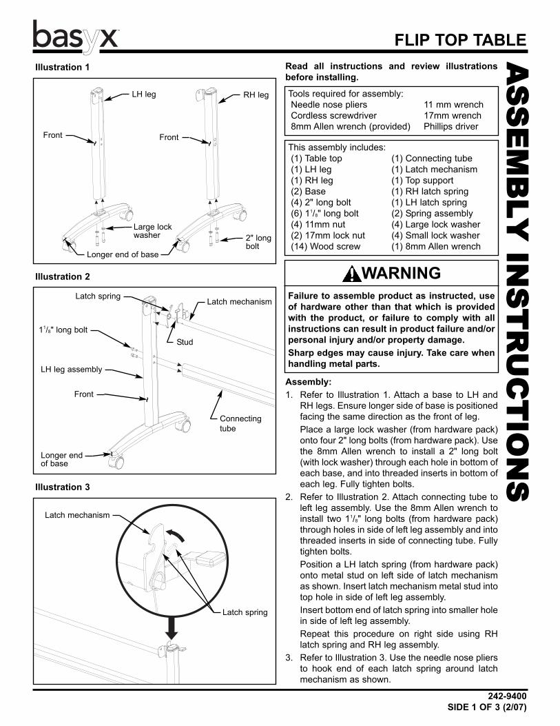
Assembly:1. Refer to Illustration 1. Attach a base to LH and
RH legs. Ensure longer side of base is positionedfacing the same direction as the front of leg.Place a large lock washer (from hardware pack)onto four 2" long bolts (from hardware pack). Usethe 8mm Allen wrench to install a 2" long bolt(with lock washer) through each hole in bottom ofeach base, and into threaded inserts in bottom ofeach leg. Fully tighten bolts.
2. Refer to Illustration 2. Attach connecting tube toleft leg assembly. Use the 8mm Allen wrench toinstall two 11/8" long bolts (from hardware pack)through holes in side of left leg assembly and intothreaded inserts in side of connecting tube. Fullytighten bolts.Position a LH latch spring (from hardware pack)onto metal stud on left side of latch mechanismas shown. Insert latch mechanism metal stud intotop hole in side of left leg assembly.Insert bottom end of latch spring into smaller holein side of left leg assembly.Repeat this procedure on right side using RHlatch spring and RH leg assembly.
3. Refer to Illustration 3. Use the needle nose pliersto hook end of each latch spring around latchmechanism as shown.
WARNING
LH leg RH leg
Front Front
2" longbolt
Large lockwasher
Longer end of base
LH leg assembly
Front
Connectingtube
Latch mechanism
Latch mechanism
Stud
Latch spring
Latch spring
11/8" long bolt
Longer endof base
~ ~
~~
~
~

FLIP TOP TABLE
242-9400SIDE 2 OF 3 (2/07)
Illustration 4
Illustration 5
Illustration 6
4. Refer to Illustration 4. Attach a spring assembly (fromhardware pack) to left side of top support. Insert end ofspring assembly threaded eye bolt through hole in bot-tom of top support and place a small lock washer ontothreaded eye bolt. Thread an 11mm nut (from hardwarepack) onto end of threaded eye bolt. Do not fully tightennut.Repeat this procedure on right side of top support.
6. Refer to Illustration 6. Onto ends of each spring assem-bly lag bolts, place a small lock washer (from hardwarepack) and thread an 11mm nut (from hardware pack). Use the 11mm wrench to fully tighten all bolts securingspring assembly to latch mechanism and top support.
5. Refer to Illustration 5. Attach top support to each legassembly. Align hole in each side of top support withhole in each top support bracket attached to each legassembly. Insert a 11/8" long bolt (from hardware pack)through each hole and thread a 17mm lock bolt ontoends of each bolt. Use the 17mm wrench and 8mm Allenwrench to tighten each bolt until end of bolt extends pastend on nut. Do not fully tighten nut.On each side of top support, insert end of spring assem-bly threaded lag bolt through hole in latch mechanism.
Top support
Top support
11mm nut
Small lock washer
Top support
11mm nut
Small lock washer
17mm lock nut
Spring assembly
Threaded eye bolt
Threaded lag bolt
Threadedlag bolt
Top support bracket11/8" longbolt
Latch mechanism
Latch mechanism
242-9400SIDE 3 OF 3 (2/07)
FLIP TOP TABLE
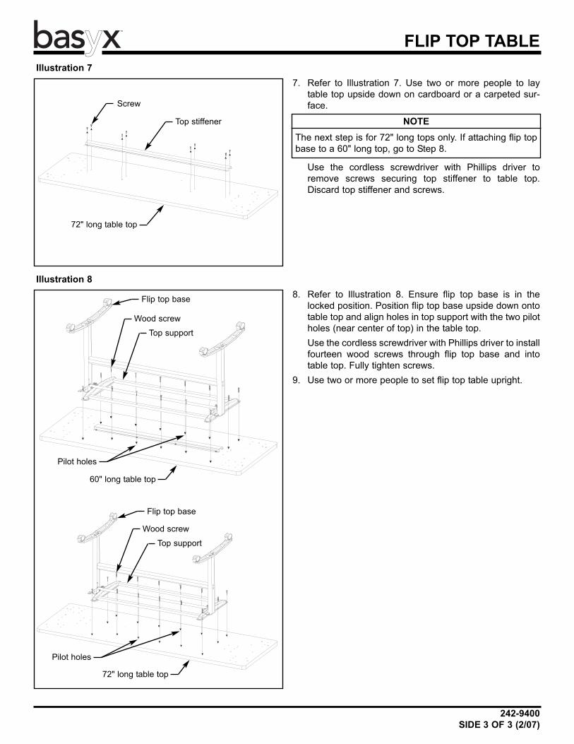
7. Refer to Illustration 7. Use two or more people to laytable top upside down on cardboard or a carpeted sur-face.
Use the cordless screwdriver with Phillips driver toremove screws securing top stiffener to table top.Discard top stiffener and screws.
8. Refer to Illustration 8. Ensure flip top base is in thelocked position. Position flip top base upside down ontotable top and align holes in top support with the two pilotholes (near center of top) in the table top.Use the cordless screwdriver with Phillips driver to installfourteen wood screws through flip top base and intotable top. Fully tighten screws.
9. Use two or more people to set flip top table upright.
Illustration 7
Illustration 8
NOTEThe next step is for 72" long tops only. If attaching flip topbase to a 60" long top, go to Step 8.
Top support
Flip top base
Wood screw
Pilot holes
Top stiffener
Screw
72" long table top
60" long table top
Top support
Flip top base
Wood screw
Pilot holes
72" long table top