Embed Size (px)
Citation preview

EARLY APOLLO SCIENTIFIC
EXPERIMENTS PACKAGE
(EASEP)
EASEP-MT-01
FLIGHT SYSTEM
FAMILIARIZATION MANUAL
PREPARED FOR
LUNAR SURFACE PROJECT OFFICE
MANNED SPACECRAFT CENTER
THE BENDIX CORPORATION
AEROSPACE SYSTEMS DIVISION
CONTRACT NUMBER
NAS 9-5829 (SA-65)
25 APRIL 1969 0


EASEP-MT-01
LIST OF EFFECTIVE PAGES
The total number of pages in this publication is 155, consisting of the following:
Page No.
Title A i thru v 1-1 thru 1-4 1-5/1-6 1-7/1-8 1-9 thru 1-10 1-11/1-12 2-1 thru 2-16 2-17/2-18 2-19thru2-28 2-29/2-30 2-31/2-32 2-33 thru 2-40 2-41/2-42 2-43 thru 2-46 2-47/2-48 2-49 thru 2-54 2-55/2-56 2-57 thru 2-80 2-81/2-82 2-83 thru 2-88 3-1 thru 3-7 4-1 thru 4-4 4-5/4-6 4-7/4-8 4-9 thru 4-25 G-1 thru G-2 A-1 thru A-14 B-1 thru B-10
Issue
25 April 1969 25 April 1969 25 April 1969 25 April 1969 25 April 1969 25 April 1969 25 April 1969 25 April 1969 25 April 1969 25 April 1969 25 April 1969 25 April 1969 25 April 1969 25 April 1969 25 April 1969 25 April 1969 25 April 1969 25 April 1969 25 April 1969 25 April 1969 25 April 1969 25 April 1969 25 April 1969 25 April 1969 25 April 1969 25 April 1969 25 April 1969 25 April 1969 25 April 1969 25 April 19 69
A


EASEP-MT -01
TABLE OF CONTENTS
Section Page
I EASEP MISSION DESCRIPTION 1-1 1-1 EASEP Mission Introduction 1-1 1-2 EASEP Mission Profile 1-1 1-3 EASEP Mission Objectives 1-3 1-4 EASEP System Description 1-3
1-5 EASEP Physical Description 1-3 1-8 EASEP Functional Description 1-4 1-15 EASEP Principal Investigators 1-10
II PASSIVE SEISMIC EXPERIMENT PACKAGE DESCRIPTION 2-1 2-1 Introduction 2-1 2-2 Structure/Thermal Subsystem 2-1
2-3 Structure/Thermal Subsystem Physical Description 2-1
2-4 Structure/Thermal Subsystem Functional Description 2-1
2-10 Modified Dust Detector Description 2-4 2-13 Electrical Power Subsystem 2-6
2-14 EPS Physical Description 2-8 2-18 EPS Functional Description 2-8 2-19 EPS Detailed Functional Description 2-8
2-22 Data Subsystem 2-12 2-23 Data Subsystem Physical Description 2-12 2-24 Data Subsystem Functional Description 2-12 2-25 Antenna Description 2-15 2-29 Data Subsystem Diplexer 2-16 2-32 Data Subsystem Command Receiver 2-22 2-35 Data Subsystem Command Decoder 2-23 2-39 Data Subsystem Central Station Timer 2-35 2-42 Data Subsystem Data Processor 2-37 2-47 Data Subsystem Transmitter 2-46 2-50 Data Subsystem Power Distribution Unit 2-52
2-56 Passive Seismic Experiment 2-61 2-57 PSE Physical Description 2-62 2-62 PSE Functional Description 2-64 2-66 PSE Detailed Functional Description 2-71
III LASER RANGING RETRO-REFLECTOR EXPERIMENT 3-1 3-1 Introduction 3-1 3-2 LRRR Physical Description 3-1
3-3 Pallet Assembly 3-1 3-6 Retro-Reflector Array Assembly 3-4 3-10 Boom Attachment and Rear Support 3-6
i

Section
3-11
EASEP-MT-01
TABLE OF CONTENTS (Cont)
LRRR FunctiOnal Description 3-14 Vertical Tilt Orientation 3-15 3-16
Azimuth Orientation and Leveling Boom Attachment and Rear Support
IV EASEP OPERATIONS 4-1 4-2 4-3 4-4
4-12
Introduction KSC Operations Ground Support Equipment Lunar Surface Operations 4-5 Flight Mode 4-6 Handling Mode 4-10 Deployment of LRRR 4-11 Deployment of PSEP Post-Deployment Operations 4-13 Manned Space Flight Network
GLOSSARY
APPENDIX A COMMAND LIST
APPENDIX B MEASUREMENT REQUIREMENTS DOCUMENT
Figure
1-1 1-2 1-3 1-4 2-1 2-2 2-3 2-4 2-5 2-6 2-7 2-8 2-9 2-10 2-11 2-12
ii
LIST OF ILLUSTRATIONS
EASEP /LM Interface Passive Seismic Experiment Package Laser Ranging Retro-Reflector Experiment EASEP Simplified Block Diagram Passive Seismic Experiment Package Structure/Thermal Subsystem Modified Dust Detector Sensor Package Dust Detector, Simplified Block Diagram Electrical Power Subsystem Electrical Power Subsystem, Functional Block Diagram EPS Power Generation Function, Block Diagram EPS Power Regulation Function, Block Diagram Data Subsystem, Simplified Block Diagram Data Subsystem Component Location Data Subsystem Functional Block Diagram Antenna and Positioning Mechanism
Page
3-6 3-7 3-7 3-7
4-1 4-1 4-1 4-1
4-12 4-12 4-12 4-17 4-17 4-17 4-22
G-1
A-1
B-1
Page
1-2 1-5 1-7 1-9 2-2 2-3 2-5 2-6 2-7
2-10 2-10 2-11 2-13 2-15 2-17 2-19

Figure
2-13 2-14 2-15 2-16 2-17 2-18
2-19 2-20
2-21 2-22
2-23 2-24 2-25 2-26 2-27
2-28
2-29 2-30 2-31 2-32 2-33 2-34 2-35 2-36 2-37 2-38 2-39 2-40
2-41
2-42 2-43 2-44 2-45 2-46 3-1 3-2
EASEP-MT-01
LIST OF ILLUSTRATIONS (Cont)
Data Subsystem Diplexer Filter Data Subsystem Diplexer Switch Data Subsystem Diplexer Switch Diagram Data Subsystem Command Receiver Data Subsystem Command Receiver Block Diagram Data Subsystem Command Receiver Output Signal Characteristics Data Subsystem Command Decoder Data Subsystem Command Decoder, Functional Block Diagram Data Subsystem Command Decoder Flow Diagram Data Subsystem Delayed Command Sequence, Functional Flow Chart Data Subsystem Central Station Timer Data Subsystem Central Station Timer, Block Diagram Data Subsystem Digital Data Processor Data Subsystem Analog Data Multiplexer/Converter Data Subsystem Data Processor, Functional Block Diagram Data Subsystem Analog Multiplexer/Converter, Block Diagram PSEP Telemetry Frame Format PSEP Telemetry Control Word Bit Assignments Data Subsystem Data Processor Flow Chart Data Subsystem Transmitter Data Subsystem Transmitter, Block Diagram Data Subsystem Power Distribution Unit Data Subsystem Power Distribution Unit, Block Diagram Data Subsystem Transmitter Power Control Command Receiver and Data Processor Power Control Passive Seismic Experiment Subsystem Passive Seismic Experiment, Functional Block Diagram PSE Long Period Seismic Activity Monitoring Function, Block Diagram PSE Short Period Seismic Activity Monitoring Function, Block Diagram PSE Data Handling Function, Block Diagram PSE Data Word Assignments in PSEP Telemetry Frame PSE Uncaging and Leveling Function, Block Diagram PSE Thermal Control Function, Block Diagram PSE Power Converter Function, Block Diagram Laser Ranging Retro-Reflector Experiment LRRR Pallet Assembly
Page
2-19 2-20 2-20 2-23 2-25
2-26 2-27
2-29 2-31
2-36 2-37 2-37 2-38 2-38
2-41
2-43 2-44 2-45 2-47 2-49 2-51 2-52 2-55 2-58 2-60 2-63 2-66
2-72
2-74 2-77 2-79 2-81 2-87 2-87
3-3 3-4
iii

iv
Figure
3-3 3-4 4-1 4-2 4-3 4-4 4-5 4-6 4-7 4-8 4-9 4-10 4-ll 4-12
Table
1-1 1-2 2-1 2-2 2-3 2-4 2-5 2-6 ? ~ .... -I
2-8 2-9 2-10 2-11
2-12 2-13
2-14 2-15 2-16 3-1 4-1
EASEP-MT -01
LIST OF ILLUSTRATIONS (Cant)
Retro-Reflector Array Retro -Reflector Mounting KSC Operations Sequence EASEP Package Handling GSE Subassembly Handling GSE Shipping Container Radioisotopic Heater Shipping Containers Astronaut Carrying PSEP Astronaut Carrying LRRR Astronaut Deploying LRRR LRRR Deployed Astronaut Deploying PSEP PSEP Deployed MSFN Functional Block Diagram
LIST OF TABLES
EASEP Scientific Objectives EASEP Principal Investigators Structure/Thermal Subsystem Leading Particulars Electrical Power Subsystem Leading Particulars Data Subsystem Component Functions Antenna Leading Particulars Data Subsystem Diplexer Filter Leading Particulars Data Subsystem Diplexer Switch Leading Particulars Data Subsystem Command Receiver Leading Particulars Data Subsystetn Command Decoder Leading Particulars Data Subsystem Delayed Command Functions Data Subsystem Data Processor Leading Particulars Data Subsystem Timing and Control Pulse Characteristics in Normal PSEP Data Mode Data Subsystem Transmitter Leading Particulars Data Subsystem Power Distribution Unit Leading Particulars PSE Leading Particulars PSE Command Functions PSE Measurements LRRR Leading Particulars Ground Support Equipment
Page
3-5 3-6 4-5 4-9
4-10 4-13 4-14 4-15 4-16 4-18 4-19 4-20 4-21 4-23
Page
1-4 1-11
2-4 2-9
2-14 2-16 2-21 2-21 2-24 2-27 2-35 2-39
2-43 2-50
2-53 2-64 2-69 2-80
3-2 4-2

EASEP-MT-01
INTRODUCTION
The Early Apollo Scientific Experiments Package (EASEP) will be used to obtain long-term scientific measurements of various physical properties and geophysical dynamics of the Moon consistent with the scientific objectives of the Apollo Program. EASEP will be transported to the lunar surface aboard the Apollo Lunar Module (LM) and will remain on the lunar surface after the return of the astronauts. EASEP will transmit scientific and engineering data to the Manned Space Flight Network (MSFN), and will establish a point reflector for precise measurement of Earth-Moon distance through laser ranging.
The purpose of the EASEP Flight System Familiarization Manual is to familiarize the reader with the scientific objectives of EASEP, equipment make-up, system deployment, and operation. This manual describes the EASEP mission and system in Section I, EASEP packages in Section II, and Section III, and operations in Section IV. Supplementary command and measurement data is provided in the Appendices.
The information contained in this manual includes formalized data released and available prior to the publication date: 25 April 1969.
v/vi


EASEP-MT -01
Section I
EASEP MISSION DESCRIPTION
1-1. EASEP MISSION INTRODUCTION
The Early Apollo Scientific Experiments Package (EASEP) is a group of scientific experiment and support subsystems which will be deployed on the surface of the Moon by an Apollo crewman. The EASEP will measure lunar seismic activity and transmit the data to receiving stations on Earth. It will establish a fiducial point consisting of an array of optical retro-reflectors to provide laser ranging for precise measurement of Earth-Moon distances. This data will be used to derive information on the composition and structure of the lunar body, its origin, and geophysical dynamics.
1-2. EASEP MISSION PROFILE
The EASEP will be transported to the Moon in the Apollo spacecraft on the first manned lunar landing mission. The Apollo· spacecraft consists of three basic modules; the service module (SM), command module (CM), and lunar module (LM). The EASEP packages will be mounted in the Scientific Equipment (SEQ) bay of the LM as shown in Figure 1-1.
A Saturn V launch vehicle will place the Apollo spacecraft in trans-lunar trajectory. After insertion of the spacecraft into lunar orbit, two crewmen will transfer from the CM to the LM for lunar descent. The third crewman will maintain the command and service module combination (CSM) in lunar orbit. The LM will be separated from the CSM and be piloted to a preselected landing site on the lunar surface.
After landing, a crewman will extract the EASEP packages from the LM and deploy them on the lunar surface. He will then verify with MSFN that the receiving, processing, and power supply subsystems are operable.
The LM will be launched from the lunar surface to rendezvous with the CSM in lunar orbit. The two crewmen will transfer from the LM to the CSM, jettison the LM in lunar orbit, and initiate the CSM transEarth maneuver. The SM will be jettisoned before re-entry and the three crewmen will re-enter the Earth atmosphere and land in the CM.
The Passive Seismic Experiment Package (PSEP) of the EASEP, on the lunar surface, is controlled by ground command from the manned space flight network (MSFN). Commands from Earth and automatically generated commands will direct PSEP operation. The Laser Ranging Retro-Reflector Experiment (LRRR) will operate in conjunction with earth based laser transmitting and receiving equipment.
1-1

1-2
I I I l ' ' '
EASEP-MT-01
FWD"
'
LM SCIENTIFIC EQUIPMENT BAY (SEQ)
EASEP PACKAGES
Figure 1-1. EASEP/LM Interface
~ ~
'
~ ~
I I I )
' ' AFT

EASEP-MT-01
1-3. EASEP MISSION OBJECTIVES
Major objectives of lunar exploration include determination of:
a. The structure and state of the lunar interior b. The composition and structure of the lunar surface and modifying processes c. The evolutionary sequence of events leading to the present lunar
configuration.
Specific EASEP mission objectives are:
a. Deploy the Passive Seismic Experiment Package (PSEP) b. Deploy the Laser Ranging Retro-Reflector Experiment (LRRR) c. Acquire rf transmission from PSEP at MSFN ground stations d. Acquire scientific data at MSFN ground stations from PSEP e. Establish and verify response of PSEP to commands from MSFN ground
stations.
To initiate partial attainment of these objectives the EASEP includes two experiments to measure a number of geophysical characteristics. The various physical and environmental properties to be measured and method of measurement are listed in Table 1-1.
1-4. EASEP SYSTEM DESCRIPTION
The EASEP is a self-contained system of scientific instruments and supporting subsystems designed to acquire lunar physical data and transmit the information to Earth. The EASEP will be deployed on the lunar surface by an Apollo crewman as described in Section IV of this manual.
1-5. EASEP PHYSICAL DESCRIPTION
The EASEP consists of two independent, self-contained experiment packages; the Passive Seismic Experiment Package (PSEP, and Laser Ranging Retro-Reflector experiment (LRRR). The EASEP packages weigh approximately 164 pounds, and occupy approximately 12 cubic feet.
1-6. PSEP Physical Description. The PSEP consists of the following subsystems:
a. Structure/thermal subsystem b. Electrical power subsystem c. Data subsystem d. Passive seismic experiment subsystem.
The PSEP weighs approximately feet in the stowed configuration. trated in Figure 1-2.
112 pounds, and occupies approximately 7. 7 cubic v The physical characteristics of PSEP are illus-
1. 7. LRRR Physical Description. The LRR consists essentially of a pallet assembly and a retro-reflector array assembly. It weighs approximately 52 pounds, and occupies approximately 4. 5 cubic feet in the stowed configuration. The physical characteristics of LRRR are illustrated in Figure 1-3.
l-3

EASEP-MT-01
Table 1-l. EASEP Scientific Objectives
Measurement Objective Experiment/Measurement Method
Natural seismology (meteoroid inpacts and moonquake s). Properties of lunar interior (existence
of core, mantle)
Determination of: l. Center of mass motion
of moon. 2. Selenophysical information
a. Forced physicallibrations b. Lunar radius
3. Geophysical information a. Fluctuation in earth rota
tion rate b. Chandler wobble of earth
axis c. Intercontinental drift
rate 4. Gravity and relativity
a. Secular change of gravitational constant g
5. Cartography 6. Space communication technology
1-8. EASEP FUNCTIONAL DESCRIPTION
Passive Seismic Experiment Package - Uses three long period seismometers in an orthogonal arrangement and one vertical short period seismometer.
Laser Ranging Retro-Reflector Experiment - Retro- reflector array serves as fiducial point on surface of moon for pre-cise measurement of distance from surface of earth using laser ranging.
The EASEP objective of obtaining lunar physical data is accomplished through employment of the two experiment packages, the manned space flight network (MSFN), and laser transmitting and receiving stations. (See Figure 1-4.)
The MSFN stations at Goldstone California, Carnarvon Australia, Ascension Island, Hawaii, Guam, and KSC Florida are the Earth terminals for communications. Mission Control Center (MCC) participates in the network for activation of the experiments, initial calibration sequences, and for the duration of the mission. Communications consist of an uplink (Earth-Moon) for command transmission to control the PSEP functions, and a downlink (Moon-Earth) for transmission of scientific experiment and engineering housekeeping data. The MSFN stations will record the downlink data.
The Air Force Electro-Optical Surveillance and Research Facility at Cloudcroft, New Mexico and the ARPA Observatory at Haleakala, Maui, Hawaii are the Earth stations for laser ranging to the LRRR. Foreign scientists are also making plans to utilize the LRRR.
1-4

PSEP DEPLOYED
PSEP STOWED
THERMAL 0 THERMAL SHROUD SHROUD
P~~ CMRS 0 t] ~
ISOTOPE HEATERS B
EASEP-MT-01
LEFT REAR SOLAR PANEL SUPPORT ASSEMBLY
BOOM AND HANDLE ASSEMBLY
CENTRAL STATION ASSEMBLY
LEFT
RIGHT REAR SOLAR PANEL SUPPORT ASSEMBLY
SOLAR PANEL ASSEMBLY
LEFT FRONT SOLAR PANEL SUPPORT ASSEMBLY
.RIGHT SOLAR PANEL ASSEMBLY
ANTENNA ASSEMBLY
Figure 1-2. Passive Seismic Experiment Package
RIGHT FRONT SOLAR PANEL SUPPORT ASSEMBLY
1-5/1-6


EASEP-MT-01
LRRR DEPLOYED
LRRR STOWED
BOOM ATTACHMENT ASSEMBLY REAR
SUPPORT
PALL£T AND ARRAY ASSEMBLY
Figure 1-3. Laser Ranging Retro-Reflector Experiment
1-7/1-8

EASEP-MT-01
1-9. PSEP Functional Description. The functional operation of PSEP is illusstrated in Figure 1-4. The following paragraphs describe the function, on a system level, of the PSEP subsystems.
1-10. Structure/Thermal Subsystem - The structure/thermal susbystem provides structural integrity and thermal protection of PSEP in transport and in the lunar environment (-300 oF to +250 oF). This includes packaging, structural support, and isolation from heat, cold, shock, and vibration. A dust detector monitors accumulation of lunar dust. Isotope heaters aid in the survival of the PSEP electronics during the lunar night.
1-11. Electrical Power Subsystem - The electrical power subsystem generates 30 to 45 watts of electrical power for operation of the PSEP. The power is developed by a solar panel array. The power is regulated, converted to the required voltage levels, and supplied to the data subsystem for distribution to the support and experiment subsystems. Analog housekeeping data is supplied to the data subsystem for downlink telemetry.
ANALOG DATA
POWER
ElECTRICAL POWER
'--- SUBSYSTEM
PULSED LASER r--------,
1 EARTH-BASED 1-----R:.:.:.A!!::D.:.::IA!!.T!:.IO~N ___ ._... LASER RANGING I LASER I RETRO-REFLECTOR L _s ~E~s~ __ _..-----R.....,EF:-LE:-:C-:::TE:-D-----:__E_xP_E_R_IM_EN_T _ __,
LASER r------, RADIATION DIGITAL I MANNED SPACE I PASSIVE DATA I FLIGHT NETWORK I L ___ --.--.J ..- SEISMIC
UPLINK DOWNLINK EXPERIMENT ANALOG
COMMANDS ENGINEERING DATA
& SCIENTIFIC
' DATA TIMING & CONTROL
DATA COMMANDS SUBSYSTEM POWER D I STR.
DIGITAL ANALOG SCIENTIFIC ENGINEERING DATA DATA
t.._ CENTRAL STATION ANALOG DATA ElECTRONICS&
DUST DETECTOR
Figure 1 -4. EASEP Simplified Block Diagram
1-9

EASEP-MT-01
1-12. Data Subsystem- The data subsystem receives, decodes, and applies discrete logic commands from the MSFN. These commands are used to perform power switching, thermal control, operating mode changes and experiment control. The data subsystem accepts and processes scientific data from the experiment, engineering status data from itself and all the subsystems, and transmits the data to the MSFN receiving stations. The data subsystem also performs the function of switching and distributing operating power to the experiment and support subsystems.
1-13. Passive Seismic Experiment Subsystem - The passive seismic experiment (PSE) will measure seismic activity of the Moon to obtain information regarding the physical properties of the lunar crust and interior. Seismic energy is expected to be produced in the lunar surface by meteoroid impacts and tectonic disturbances.
The seismic activity is measured by long period and short period seismometers which monitor the displacement of inertial masses from a zero position relative to sensitive transducers.
1-14. LRRR Functional Description. The LRRR will serve as a fiducial point on the surface of the moon for precise measurement by laser ranging of the distance from sites on earth. The retro-reflector array will be aimed toward the earth. Laser radiation incident upon the retro-reflectors is reflected on a path nearly parallel to the incident beam.
The pallet assembly provides structural integrity and contributes to thermal isolation of the array assembly in the lunar environment. It provides for aiming and alignment of the array assembly.
The array assembly provides passive thermal control to minimize thermal gradients in the retro- reflectors.
1-15. PRINCIPAL INVESTIGATORS.
Each EASEP experiment has been designed by a principal investigator (PI), in some cases in conjunction with one or more co-investigators. The investigators, identified by experiment, are listed in Table 1-2.
1-10

EASEP-MT-01
Table 1-2. EASEP Principal Investigators
Principal Investigator and Experiment Co-Investigators
Passive Seismic
Laser Ranging Retro-Reflector
Principal Investigator Dr. Gary Latham-
Lamount Geological Observatory Co-Investigators
Dr. George Sutton -University of Hawaii
Dr. Frank Press -Massachusetts Institute of Technology
Dr. Maurice Ewing -Columbia University
Principal Investigator Dr. C. 0. Alley -
University of Maryland Co-Investigators
Dr. P. L. Bender -National Bureau of Standards University of Colorado
Dr. R. H. Dicke -Princeton University
Dr. J. E. Faller -Wesleyan University
Dr. G. J. F. MacDonald -University of California Santa Barbara
Dr. H. H. Plotkin -Goddard Space Flight Center
Dr. D. T. Wilkinson -Princeton University
Dr. W. M. Kaula-University of California Los Angeles
l-11/l-12


EASEP-MT- 01
SECTION II
PASSIVE SEISMIC EXPERIMENT PACKAGE DESCRIPTION
2-1. INTRODUCTION
This section describes the four (one experiment and three support) subsystems which comprise the passive seismic experiment package (Figure 2-1 ). A listing of the subsystems follows:
a. Structure/thermal subsystem b. Electrical power subsystem (EPS) c. Data subsystem (DS/S) d. Passive seismic experiment subsystem (PSE)
All subsystems are described in terms of their physical characteristics, functional operation, and system interfaces.
2-2. STRUCTURE/THERMAL SUBSYSTEM
The structure/thermal subsystem provides the structural integrity and thermal protection required by the PSE and support subsystems to withstand the environments encountered in storage, transportation and handling, testing, loading on LM, space flight, and lunar deployment. During operation on the Moon, the structure/thermal subsystem will continue to provide structural support and thermal protection to the data subsystem, the electrical power subsystem, and the passive seismic experiment.
2-3. STRUCTURE/THERMAL SUBSYSTEM PHYSICAL DESCRIPTION
The structure/thermal subsystem comprises the central station assembly which is the basic structural assembly of the PSEP. It includes the primary structure, mounting plate, thermal plate, thermal bag, isotope heaters, modified dust detector, and boom and handle assemblies as shown in Figure 2-2. Structure/ thermal leading particulars are listed in Table 2-1.
2-4. STRUCTURE/THERMAL SUBSYSTEM FUNCTIONAL DESCRIPTION
2-5. Primary Structure. The primary structure provides tie points for securing the PSEP in compartment 1 of the SEQ bay of the LM. It is recessed to receive the central station electronics which are mounted on the thermal plate and enclosed by the thermal bag. Thermistor temperature sensors monitor the primary structure temperature during operation. Temperature signals are supplied to the data subsystem for insertion into the PSEP telemetry data. Tiepoints are provided for the modified dust detector, solar panels, antenna and positioning mechanism, and boom and handle assembly.
2-1

ANTENNA ASSEMBL
BOOM AND HANDLE ASSEMBLY
LEFT
EASEP-MT- 01
PSE
IKSC HANDliNG MODEU
RIGHT SOLAR PANEL ASSEMBLY
Figure 2-1. Passive Se1smic Experiment Package
2-6. Mounting Plate. The mounting plate provides tie points for mounting the PSE sensor assembly and isotope heaters. The mounting plate provides thermal protection for the PSEP through the use of thermal control paint, second-surface mirrors, and insulation.
2-7. Thermal Plate and Thermal Bag. The thermal plate and thermal bag provide thermal protection for the central station electronics. A thermistor temperature sensor monitors thermal plate temperature during operation and supplies temperature signals to the data subsystem for insertion into the PSEP telemetry data.
2-8. Isotope Heaters. Two radioisotope heaters generate 30 (± 0.'5) watts of thermal energy to aid in the survival of the PSEP electronics during the lunar night when the central station is not operating.
2-9. Boom and Handle Assembly. The PSEP is lowered from compartment No. 1 of the LM SEQ bay to the lunar surface by means of the boom and handle assembly. During deployment, the astronaut handle is extended to allow emplacement (alignment and leveling} of the PSEP. Lanyards protruding through the astronaut handle release the solar panel and antenna deployment mechanisms.
2-2
MOUNTING PLATE
EASEP-MT -01
0 <8> 0
Q <:§> ISOTOPE H HEATERS u
THERMAL PLATE
............ ---IMOUNTING CENTRAL STATION ELECTRONICS I
Figure 2-2. Structure/Thermal Subsystem
BOOM AND HANDLE ASSEMBLY
2-3

EASEP-MT -01
Table 2-1. Structure/Thermal Subsystem Leading Particulars
Component Characteristic
Central Station Assembly (primary structure, mounting plate, thermal plate, electronics, thermal bag)
Isotope Heater
Boom and Handle Assembly
Modified Dust Detector
Sensor Package
Circuit Board
Size (inches)
Weight (pounds)
Size (inches)
Weight (pounds) Thermal Output (watts)
Length (inches) Weight (pounds)
Power Requirements On mode
Off mode
Analog Outputs
Size (inches)
Weight (pounds)
Size (inches) Weight (pounds)
2-10. MODIFIED DUST DETECTOR DESCRIPTION
Value
L 26.75 w 27.37 H 6. 87
87.38
H 3.20 D 3.00
2.20 15.00
16.00 1. 90
245 mw maximum+ and -12 vdc. 45 mw maximum, +and -12 vdc. 0 to +5 vdc.
1.75xl.75x 1. 75 o. 35
3.3x6.l 0.26
The modified dust detector (Lunar Degradation Experiment) will obtain data for assessment of dust accretion on EASEP, the radiation environment, and the degra
dation rate of thermal coatings.
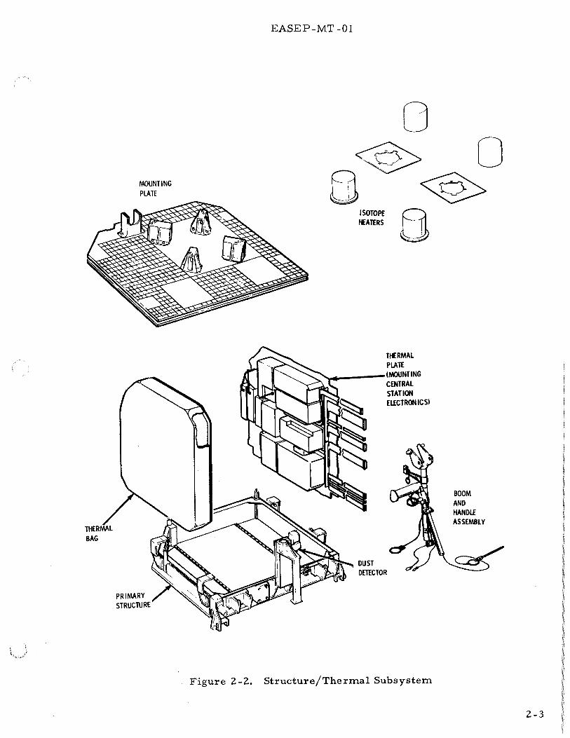
2-11. Modified Dust Detector Physical Description. The modified dust detector has two components; a sensor package (Figure 2-3 ), and a printed circuit board. The sensor package is mounted on the PSEP central station. It has three 1 em by 2 em solar cells located on the top, horizontal, surface. One cell has a 20 mil radiation shield cover glass, one cell has a 6 mil cover glass, and one cell has no cover glass. A thermister is attached to the rear of the two outboard cells, and a third thermister is mounted on the outboard vertical side of the package. The sensor package is connected through an H-film cable to the printed circuit board which is located in the power distribution unit of the data subsystem.
2-4
EASEP-MT -01
SOLAR CELLS
Figure 2-3. Modified Dust Detector Sensor Package
2-12. Modified Dust Detector Functional Description. Dust accretion on the solar cells will reduce the intensity of solar radiation reaching the three cells. This can be measured by an equal reduction in output from the cells as a function of the amount of dust.
The radiation environment will be measured by the reduction of solar cell output voltages due to radiation degradation of the cells. One solar cell has no cover glass radiation shield, and is used as a base cell. The other two cells have radiation shields of different thickness. The different thicknesses of radiation shield cover glasses on the cells will provide different degrees of radiation protection dependent upon the particle energies, so that they form a simple spectrometer.
Two thermisters will measure solar cell temperatures, and the thermister on the sensor side will measure lunar surface temperature in the range of -308 "F to 274"F.
The outputs of the solar cells are applied to three amplifiers which condition the signals and apply them to three subcommutated analog data channels of the data subsystem. (See Figure 2-4. ) The thermistor outputs are applied to three subcommutated analog data channels of the data subsystem.
Modified dust detector operation is controlled by on and off commands from Earth. These commands are applied to the command memory through the data subsystem. The command memory stores the command and controls the operation of the power
2-5

< FROM DATA SUBSYSTEM
' ON
OFF
-12 VDC
+12 VDC
'
....
EASEP-MT -01
COMMAND MEMORY
l SWITCHED - 12 VDC
POWER SWITCH SWITCHED +12 VDC
AMPLIFIER
SOLAR CELL {3)
~ ILLUMINATION DETECTOR /
(3) / THERMISTOR TEMPERATURE DETECTOR
(3)
ANALOG ILLUMINATION DATA
ANALOG TEMPERATURE DATA
•
)
,
TO DATA SUBSYSTEM
Figure 2-4. Dust Detector, Simplified Block Diagram
switches in accordance with the command. The two solid state switches control the application of +12 vdc and -12 vdc operating power from the data subsystem. Individual fusing protection is provided on each of the two voltages.
2-13. ELECTRICAL POWER SUBSYSTEM
The electrical power subsystem (EPS) provides power for lunar operation of the PSEP. Primary electrical power is developed by two solar panel arrays. Primary power at 16. 2 ± 0. 02 volts is supplied to the power conditioning unit (PCU). Voltage conversion circuits in the PCU convert the primary power to regulated and filtered operating voltages for the experiment and support subsystems.
2-14. EPS PHYSICAL DESCRIPTION
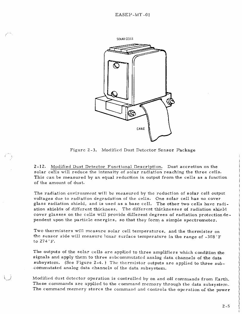
Major components of the electrical power subsystem are shown in Figure 2-5. The components are the solar panel array and power conditioning unit.
2-15. EPS Solar Panels. The solar panel array consists of six solar panels. Two solar panel assemblies of three panels each are attached to the primary structure by deployment linkages which erect the panels to the correct operational attitude of 60 o with the horizontal lunar surface. Electrical cables connect the solar panels to the PCU. In the stored configuration, the outboard solar panels fold on the center panel, and are secured with front and rear supports.
2-6
POWER CONDITIONiNG UNtT

EASEP-MT -01
2-16. EPS Power Conditioning Unit (PCU). The functional elements of the PCU are redundant de voltage converters and shunt regulators, filters, and two command control amplifiers. The elements are mounted on printed circuit boards and attached to the center and lower sections of the PCU case.
Shunt regulator load and dissipative elements are mounted in a power dissipation module external to the central station along the rear of the primary structure.
2-17. EPS Leading Particulars. The physical and electrical characteristics of the electrical power subsystem are given in Table 2-2.
2-18. EPS FUNCTIONAL DESCRIPTION
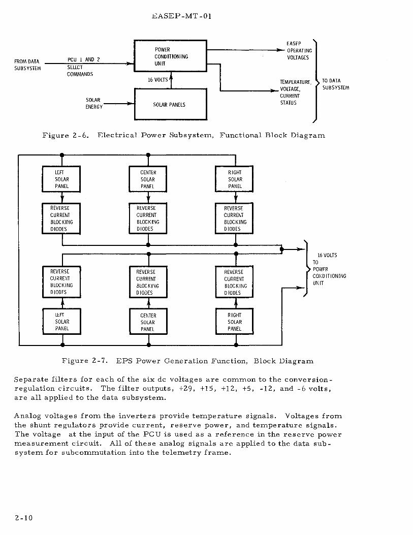
As shown in Figure 2-6, the solar panels supply primary power at 16 volts to the PCU. Voltage conversion circuits in the PCU convert the primary power to the six PSEP operating voltages. The PCU starts automatically when there is an output from the solar panels.
Commands CU -01 and CU -02 from the data subsystem signal control circuits to activate one of the other of the redundant converter -regulator circuits in the PCU.
Analog voltages from the PCU provide temperature, voltage, and current status to the data subsystem.
2-19. EPS DETAILED FUNCTIONAL DESCRIPTION
2-20. EPS Solar Panels. Operation of the solar panels is illustrated in the block diagram of Figure 2-7. Solar energy is converted to electrical power by the solar panel array. The electrical power produced by the solar panels provides 30 to 45 watts to the PCU.
Each solar panel is composed of 420 solar cells wired in a series parallel configuration to provide high reliability. Blocking diodes located on the back side of the center panels prevent reverse currents in the solar panels. There are three paralleled diodes in series with each solar panel to provide higher reliability by redundancy.
2-21. EPS Power Conditioning Unit. The power conditioning unit performs two major functions:
a. Voltage conversion b. Voltage regulation
The PCU contains redundant power conditioners. As shown in Figure 2-8, each power conditioner consists of a de-to-de power converter (inverter and rectifiers), which converts the 16-volt input to the six operating voltages, and a shunt volt-age regulator to maintain the output voltages within approximately ± 1 o/o. The input voltage is also regulated by this action because of the fixed ratio converter.
2-8

EASEP-MT-01
Table 2-2. Electrical Power Subsystem Leading Particulars
Component Characteristic Value
Solar Panels Output Power 34 to 46 watts
Output Voltage 1 6. 0 ± 0. 2 vdc
Length (each panel) 23. 7 5 inches Height (each panel) 13. 0 inches Thickness (each panel) 0. 375 inches Weight (Total, 6 panels) 12. 24 pounds Solar Cells per panel 420
(2520 Total)
Power Conditioning Unit N aminal Outputs +29 vdc at 0. 63 amps
+ 15 vdc at 0. 0 1 amp +12 vdc at 0. 21 amp +5 vdc at 0. 48 amp -6 vdc at 0. 04 amp -12 vdc at 0. OS amp
Output Voltage Regulation ± 1 percent
Length 8. 36 inches Width 4. 14 inches Height 2. 94 inches Weight 4. 5 pounds
The +16 volts from the solar panels is applied through the switching circuit to the selected de -to-de converter, applying power to the inverter and completing the shunt regulation circuit. Applying power to the inverter permits it to supply ac power to the rectifiers that develop the de voltages applied to the filters. The outputs from the filters are the six operating voltages applied to the data subsystem power distribution unit. Output and input voltages are regulated by feedback from the + 12 volt output to the shunt regulator.
The shunt regulator consists of amplifiers inside the power conditioning unit and resistors in the power dissipation module outside the central station. With the resistors outside the central station, some of the excess power is radiated to space and does not contribute heat to central station. Power dissipation resistance PDR 1 will dissipate 5 watts of power, and PDR 2 will dissipate 10 watts. The range of the regulators is 36 watts. All the output voltages are regulated by the 12-volt feedback since they are coupled in the output transformer. The +12 volt is applied to the switching circuit for determining over or under voltage and switching to the redundant inverter and regulator, if necessary.
2-9
FROM DATA SUBSYSTEM
£ASEP-MT -01
POWER
PCU 1 AND 2 CONDITIONING
SELECT UNIT -
COMMANDS 16 VOLTSt
SOLAR ENERGY SOLAR PANELS
TE
EASEP OPERATING VOLTAGES
vo MPERATURE, LTAGE, RRENT ATUS
cu ST
TO DATA SUBSYSTEM
Figure 2-6. Electrical Power Subsystem, Functional Block Diagram
- -T T
LEFT CENTER SOLAR SOLAR PANEL PANEL
t t REVERSE REVERSE CURRENT CURRENT BLOCKING BLOCKING D lODES DIODES
I l -
I T REVERSE REVERSE CURRENT CURRENT BLOCKING BLOCKING DIODES D lODES
• • LEFT CENTER SOLAR SOLAR PANEL PANEL
l l
I RIGHT SOLAR PANEL
t REVERSE CURRENT BLOCKING D lODES
l -T
REVERSE CURRENT BLOCKING D lODES
• RIGHT SOLAR PANEL
l
' T
I
16 VOLTS TO POWER CONDITIONING UNIT
Figure 2-7. EPS Power Generation Function, Block Diagram
Separate filters for each of the six de voltages are common to the conversionregulation circuits. The filter outputs, +29, +15, +12, +5, -12, and -6 volts, are all applied to the data subsystem.
Analog voltages from the inverters provide temperature signals. Voltages from the shunt regulators provide current, reserve power, and temperature signals. The voltage at the input of the PC U is used as a reference in the reserve power measurement circuit. All of these analog signals are applied to the data subsystem for subcommutation into the telemetry frame.
2-10

N I
.......
.......
VOLTAGE +12 VDC PROTECTION
TEMP SIG ...... DC POWER
COMMANDS r--+ INVERTER A/C POWER RECTIFIERS
FROM DATA SUBSYSTEM
PCU #1 SELECT +12 VDC
PCU #2 SELECT SHUNT TEMP SIG
l I REGULATOR CURRENT SIG
!6VDC FROM RESERVE POWER SOLAR PANELS SWITCH
CIRCUIT
TEMP SIG
INVERTER AC POWER RECTIFIERS
SHUNT TEMP SIG ........
REGULATOR CURRENT SIG
RESERVE POWER
NOTE: ANALOG TEMPERATURE AND POWER MEASUREMENT SIGNALS ARE APPLIED DIRECTLY TO THE DATA SUBSYSTEM.
FILTERS
l DC POWER
+12 VDC
+29 VDC
' +15 VDC
+12 VDC
+S VDC
-12 VDC j -6 VDC
Figure 2-8. EPS Power Regulation Function, Block Diagram
TO DATA SUBSYSTEM
M > (/).
M 1:j I
$:: t-3 I 0 -

EASEP-MT -01
2-22. DATA SUBSYSTEM
The data subsystem is the focal point for control of the PSE sensor and the collection, processing and transmission of scientific data and engineering status data to the Manned Space Flight Network (MSFN). To accomplish the basic functions of (a) reception and decoding of uplink (Earth-to-Moon) commands, (b) timing and control of PSEP subsystems, and (c) the collection and transmission of downlink (Moon-to -Earth) scientific and engineering data, the data subsystem consists of an integration of units interconnected as shown in Figure 2-9. The uplink shown in Figure 2-9 requires the antenna, diplexer, command receiver, and command decoder components of the data subsystem. The downlink requires the data processor, transmitter, diplexer and antenna components. The major components of the data subsystem and associated functions are listed in Table 2-3.
2-23. DATA SUBSYSTEM PHYSICAL DESCRIPTION
The data subsystem components are mounted on a section of the central station thermal plate. Figure 2-10 shows data subsystem component location within the central station. A pre-formed harness electrically connects the components. The harness is attached to each component with a multipin connector. Power for each unit and electrical signals are conducted to and from each component via the harness. Coaxial cables connect the command receiver and transmitters to the diplexer switch and thence to the antenna. Other items installed within the central station include five central station temperature sensors.
' The overall weight of the data subsystem is approximately 25 pounds and the power consumption is approximately 15 watts.
2-24. DATA SUBSYSTEM FUNCTIONAL DESCRIPTION
Uplink command data transmitted from the MSFN is received by the data subsystem antenna, routed through the diplexer, demodulated by the command receiver, decoded by the command decoder, and applied to the experiment and support subsystems as discrete commands. The discrete commands control experiment and support subsystem operations and initiate command verification functions.
Downlink data consists of analog and digital data inputs to the data processor from the experiment and support subsystems in response to periodic demands from the data processor. Scientific inputs to the data processor from the PSE subsystem are in digital form. Engineering data is usually analog and consists of status and housekeeping data such as temperatures and voltages which reflect operational status and environmental parameters. The data processor accepts binary and analog data from the experiment and support subsystems. It generates timing and synchronization signals, converts analog data to digital form, formats digital data, and provides data in the form of a split-phase modulated signal to the transmitter. The transmitter generates the downlink transmission carrier and phase
2-12

UPLINK (COMMANDS)
COMMAND RECEIVER
TIMER
COMMAND DECODER
COMMANDS TO EXPERIMENT AND SUPPORT SUBSYSTEMS
EASEP-MT -01
DOWNLINK (SCIENTIFIC & ENGINEERING DATA)
\ I
\ LENNA DIPLEXER & SWITCH
POWER DISTRIBUTION
UNIT
ELECTRICAL POWER TO ALL SUBSYSTEMS
TRANSMITTER (A AND B)
__., DATA PROCESSOR
(X ANDY)
t SCIENTIFIC AND ENGINEERING DATA FROM EXPERIMENT AND SUPPORT SUBSYSTEMS
Figure 2-9. Data Subsystem, Simplified Block Diagram
modulates that carrier with the signal from the data processor. The transmitter signal is selected by the diplexer switch and routed to the antenna for downlink transmission to the MSFN.
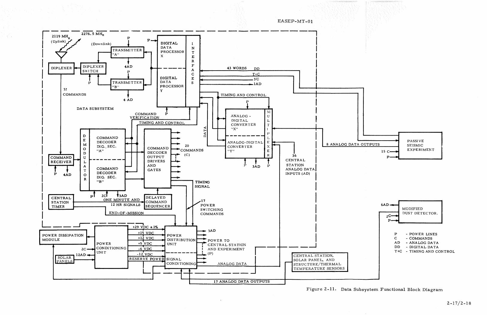
Figure 2-11 shows a functional diagram of the data subsystem and its interfaces with the PSE subsystems. Redundant channels are provided for the transmitter and portions of the command decoder and data processor to improve system reliability.
The uplink transmission from MSFN is a 2119 MHz RF carrier with a 2 KHz data subcarrier modulated to a 1 KHz synchronizing subcarrier. The command receive receiver demodulates the carrier and provides the composite 2 KHz and 1 KHz subcarrier to the command decoder. The command decoder demodulator section detects the 2 KHz command data subcarrier and 1 KHz timing signal and applies both to the redundant digital decoder sections (A and B) of the command decoder. The digital decoder sections identify correct address codes, decode the digital data commands, issue command verification signals to the data processor, and apply command signals to the PSE and support subsystems.
2-13

EASEP-MT-01
Table 2-3. Data Subsystem Component Functions
Component Function
Antenna Provides simultaneous uplink reception and downlink transmission of PSEP signals.
Diplexer switch Connects either transmitter to the antenna.
Diplexer filter Connects receiver input and transmitter output to the antenna.
Transmitter Generates Moon-to-Earth downlink signals.
Command receiver Accepts Earth-to -Moon uplink signal.
Command decoder Decodes received command signals and issues commands to the system.
Central station timer Provides backup timing signals following departure of astronauts. Switch transmitter off after 720 days ± 30 days.
Data processor Collects and formats scientific data inputs from the experiments. Collects and converts analog housekeeping data into binary form.
Power distribution Controls power switching and conditions engineering status data.
The central station timer provides timing signals to the command decoder delayed command sequencer which are used to initiate a series of delayed commands to activate certain system operations. The specific functions of the delayed commands are discussed in the detailed command decoder paragraph.
Analog signals from the experiment and support subsystems are applied directly to the analog multiplexer or indirectly through the signal conditioning section of the power distribution unit to the analog multiplexer. The 90-channel analog multiplexer processes the analog inputs and applies them to the inputs of redundant analog-to-digital converters (X and Y). The digital outputs from the analogto-digital converters are applied to redundant digital data processors (X andY) along with digital data from the command decoder and the experiment subsystems.
The digital data process or generates timing and control signals for use throughout the system and formats the scientific and engineering data from the experiment and support subsystems for downlink transmission. Redundant transmitters (A and B) receive the PCM signal from the data processors. A diplexer switch connects the transmitter in use to the antenna for downlink transmission to Earth.
2-14

EASEP-MT -01
CENTRAL STATION
rn~;:---- ---I SUBSYSTEM
TRANSMITTER B
I I I I I I I I
II ..===========:::::;"'1 II
TRANSMITTER A
I I
COMMAND RECEIVER
-;0~;- 911,..-----CON- POWER DITIONING I DISTRIUNIT I BUTION
UNIT
I I I I
I
·---- 11----~
DIPLEXER FILTER
DATA PROCESSOR
I
1-, I I I I l
ANALOG MULTIPLEXER
__ ,__, __ _ ----..1
~ L _____ _ _______ !...__ _ _,
COMMAND DECODER
------
PASSIVE SEISMOMETER
Figure 2-10. Data Subsystem Component Location
2-25. ANTENNA DESCRIPTION
I I I I
The antenna is a modified axial helix designed to receive and transmit a righthand circularly polarized S-Band signal. This antenna type was selected because it has a relatively high gain over a moderately narrow beamwidth.
2-26. Antenna Physical Description. The antenna consists of a copper conductor bonded to a fiberglass-epoxy tube for mechanical support. Figure 2-12 shows the antenna. The helix is 23 inches in length and 1-1/2 inches in diameter. A 5-inch ground plane with a 2-.inch-wide cylindrical skirt is attached to one end of the helix and functions as a wave launcher for the electromagnetic wave in the transition from coaxial transmission line mode to the helix mode. An impedance matching transformer is located at the antenna feed point to match the higher impedance of the helical antenna to the 50-ohm coaxial transmission line. The weight of the antenna, including cables, is 1. 28 pounds.
The entire antenna is coated with a white, reflecting thermal paint for thermal protection during the high temperature range of lunar day. Antenna leading particulars are listed in Table 2-4.
2-15

EASEP-MT -01
Antenna gain is referenced to a right hand circularly polarized isotropic level and does not include coaxial cable loss which is typically 1. 1 db.
Table 2-4. Antenna Leading Particulars
Characteristic Transmit Receive
Gain
on boresight 16. 0 db 15. 2 db
beamwidth at 11. 0 db gain 36°
beamwidth at 11. 5 db gain 33°
Axial ratio 1. 3 db 1. 0 db
Input VSWR 1. 20 :1 1. 20:1
Sidelobe level -11 db -11. 3 db
2-27. Antenna Functional Description. The antenna receives command signals from Earth on a frequency of 2119 MHz and transmits telemetry data on the frequency of 2276. 5 MHz. Antenna gain is in the order of 15. 2 db and the beamwidth is sufficiently broad to cover the Earth at all times.
2-28. Antenna Positioning Mechanism- The antenna will be pointed to Earth by means of the antenna positioning mechanism. Elevation angle of the antenna depends on the lunar site selected. The antenna is manually positioned to the appropriate elevation angle corresponding to any one of five lunar sites. Detents on the index plate retain the position selected. Antenna position is indicated by the index pointer and site-numbered marks on the index plate.
2-29. DATA SUBSYSTEM DIPLEXER
The diplexer consists of the diplexer filter and the diplexer circulator switch.
2-30. Data Subsystem Diplexer Physical Description. The diplexer filter and circulator switch are shown in Figures 2-13 and 2-14, respectively. Figure 2-15 shows a diagram of the circulator switch. The diplexer filter contains a transmit frequency bandpass filter, a receiver frequency bandpass filter and a common path antenna lowpass filter. The three filters are coupled at a common junction at the end opposite the circulator switch, receiver, and antenna ports. The input and output connectors are miniature, coaxial, right-angle connectors made of gold-plated stainless steel. Matching impedance for the antenna, transmit and receive connectors is 50 ohms. Leading particulars of the diplexer filter are listed in Table 2-5.
2-16
EASEP-MT-01
r - - - i276.-s ;:rn:-1 2119 MHZ p
------------, I I I I I I I I I I I I I l I I I I I
( Uplinky / (Downlink). ____ ...._~--... p....,. DIGITAL
Jl' '/ ----thRANSMITTER ~ y "A"
t
DATA PROCESSOR X
DIPLEXER f4- DIPLEXER SWITCH
4AD .. ....., ____ _
:37
COMMANDS
f p
f TRANSMITTER ..__
...__-I"B" r .......___...,.._.~__,
4 AD
DIGITAL DATA PROCESSOR y
DATA SUBSYSTEM
D COMMAND E DECODER M
COMMAND VERIFICATION
TIMING AND CONTROL
~
20
I N T E R F A c E s
43 WORDS DO
T+C
1+---------- 3'C ~----------------_.-lAD
TIMING AND CONTROL
~ ........ ANALOG-
DIGITAL CONVERTER "X"
---------~.......,
ANALOG-DIGITAL DIG., SEC.
0 "A" D
COMMAND u
COMMAND DECODER OUTPUT DRIVERS AND GATES
f----. coMMANDS f--r (C)
CONVERTER "Y"
j-.-,_ ________
RECEIVER L
! ~ A ,__ T
COMMAND
4AD 0 DECODER
R DIG. SEC. "B"
t 2cf hAn f C ENTRAL pi DELAYED
ONE MINUTE AND STATION 1------_;::;.:.;.:;:....:.;.:.:.:.;:..;;;..;;;..;;;;...;,;;;.;.;;;;. .... COMMAND TIMER 12 HR SIGNALS SEQUENCER
I END-OF-MISSION
--1.. _,.. _,.. 1--+-
TIMING SIGNAL
1 ..,.11 V POWER
/ SWITCHING COMMANDS
! 310
1\[
u L T 1 p
L E X E R
l
~
36 CENTRAL
STATION ANALOG DATA INPUTS (AD)
r I I J
I I I
l I I I 1 I
8 ANALOG DATA OUTPUTS
L r-----------. -----' +29 VDC :t:lo/o
POWER DISSIPATION ~ MODULE
POWER
2c--. CONDITIONING UNIT
..---......., ... 12AD..,...
I SOLAR I PANELS_I~-----!~
,-_,__ -__ -__ --' ______ .., CENTRAL STATION,
I SOLAR PANEL, AND ANALOG DATA i r-- STRUCTURE/THERMAL
--- J TEMPERATURE SENSORS
I-- 3AD .__...;+..:.l,._S_V~D=->C'"'---W POWER ~
+12 VDC ~ DISTRIBUTION~ POWER TO +5 VDC ~ UNIT : CENTRAL STATION -6 VDC I AND EXPERIMENT
-12 VDC --------~(P) RESERVE POWER SIGNAL ~
' CONDITIONING~
L~ ---1-~- --._ __________________ ......... 17 ANALOG DATA OUTPUTS
15 c__.,
PASSIVE SEISMIC EXPERIMENT
p---L---------~
6AD-MODIFIED
2c--. DUST DETECTOR.
p--.
p - POWER LINES c -COMMANDS AD -ANALOG DATA DO -DIGITAL DATA T+C - TIMING AND CO NTROL
Figure 2-11. Data Subsystem Functional Block Diagram
2-17/2-18


CABLE CONNECTOR
EASEP -MT- 0 I
NON-FLIGHT PIN
{KSC HANDLING MODELl
RO
Figure 2-12. Antenna and Positioning Mechanism
Figure 2-13. Data Subsystem Diplexer Filter
2-19

EASEP-MT-01
Figure 2-14. Data Subsystem Diplexer Switch
DIPLEXER FILTER
TRANSMITTER PORT
___,/ -+------+12 v
ARC
SUPPRESSION
12 V RETURN
LOAD A
TEMP
COMP REVERSIBLE CIRCULATOR
FIXED DIRECTIONAL CIRCULATORS
INPUT TRANSMITTER A
INPUT TRANSMITTER B
LOAD B
Figure 2-15. Data Subsystem Diplexer Switch Diagram
2-20

EASEP-MT -01
Table 2-5. Data Subsystem Diplexer Filter Leading Particulars
Characteristic Value
Receiver path (includes band-pass and low-pass filter)
Insertion loss VSWR Center frequency Max 3 db bandwidth Min 3 db bandwidth
Transmitter path (includes band-pass and low-pass filter)
Insertion loss VSWR Center frequency Max 3 db bandwidth Min 3 db bandwidth Power handling capability Weight
1. 30 db 1.10:1 2119 MHz 11.0 MHz 11.0 MHz
0.70 db 1. 10:1 227 5-2280 MHz
45 MHz 4. 5 MHz
20. 0 watts 0. 9 pounds
Form factor 6. 8 x 2. 5 x 2. 5 inches
The diplexer switch consists of three circulators, two loads, and three external ports. The circulator uses copper-clad dielectric board stripline techniques. The input and output connectors consist of three right angle connectors; one for the interconnecting line to the diplexer filter section, and one each to the two transmitters. Two solder terminals are provided for the ± 12 volt switching power. Leading particulars of the diplexer switch are listed in Table 2-6.
Table 2-6. Data Subsystem Diplexer Switch Leading Particulars
Characteristic
Insertion loss VSWR Center frequency Isolation for 3 db bandwidth (4 MHz) Switching voltage DC power (position B) DC power (position A) Switching time RF power capability Weight Stray magnetic field (steady-state) Form factor
Value
0. 5 db l. 14:1
30-40 db 12 vdc 150 MW 0 120 milliseconds 1. 5 watts 1. 28 pounds 10 gamma at 3 feet 4 x 4. 5 x 1. 3 inches
2-21

EASEP-MT-01
2-31. Data Subsystem Diplexer Functional De scription. The bandpass filter for the transmit and receive arms of the dip1exer filter consist of five elements coupled to provide the attenuation required at the transmit frequencies, receive frequencies, image, and local oscillator and transmitter spurious frequencies. The low-pass filter is an unbalanced ladder filter intended to augment the transmitter bandpass filter in suppressing the above-center-frequency spurious transmitter outputs. The diplexer circulator switch assembly couples the selected transmitter (A or B) through the diplexer filter assembly to the antenna. The switch also provides isolation protection to the transmitters and connecting equipment from opens, shorts, or simultaneous transmitter antenna feed. The circulator switch is reversible to serve as a transmitter selector switch and requires a +12 vdc signal to switch the back-up transmitter into operation.
2-32. DATA SUBSYSTEM COMMAND RECEIVER
The command receiver demodulates the 2119 MHz phase-modulated uplink carrier transmitted from MSFN, provides a combined hi-phase modulated 2 KHz data subcarrier and 1 KHz synchronizing subcarrier to the command decoder, and supplies analog status data to the data processor.
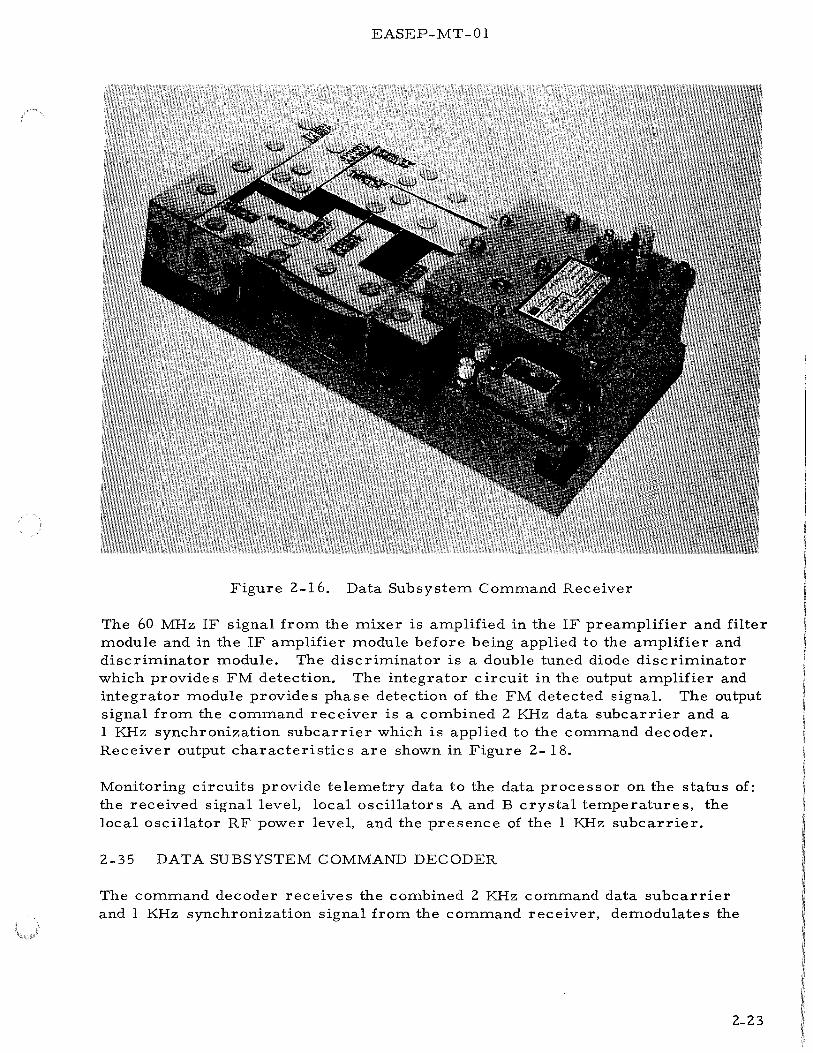
2-33. Data Subsystem Command Receiver Physical Description. Figure 2-16 shows the command receiver. The command receiver contains foam-potted individually shielded circuit modules mounted on a milled magnesium base plate. Module interconnections are routed through channels milled into the base plate. Receiver leading particulars are listed in Table 2-7.
2-34. Data Subsystem Command Receiver Functional Description. Figure 2-17 shows a detailed block diagram of the command receiver. The 2119 MHz phasemodulated uplink carrier is received by the central station antenna, coupled through the diplexer, and applied to the command receiver mixer. The input signal is mixed with a crystal controlled 2059 MHz local oscillator signal to produce a 60 MHz intermediate frequency signal. Two local oscillator/driver amplifier circuits are used to provide redundant operation. The oscillator/driver amplifier output frequency of 128.7 MHz is increased to 2059 MHz by a multiply-by-16 frequency multiplier. The two 2059 MHz signals from the frequency multipliers are applied to a stripline hybrid which is the redundancy combiner for the redundant local oscillators. From the hybrid, the 2059 MHz local oscillator frequency is applied to the mixer.
The level sensor and local oscillator switch circuits determine which local oscillator provides the local oscillator signal. Mixer circuit diodes apply bias voltage to an amplifier which controls an integrated circuit flip-flop. When the bias voltage falls below an acceptable threshold, the amplifier causes the flip-flop to change state. The flip-flop change of state de energizes one local oscillator chain and energizes the redundant local oscillator chain. Adequate time delays are provided to prevent switching during receiver turn-on and signal transients.
2-22
EASEP-MT-01
Figure 2-16. Data Subsystem Command Receiver
The 60 MHz IF signal from the mixer is amplified in the IF preamplifier and filter module and in the IF amplifier module before being applied to the amplifier and discriminator module. The discriminator is a double tuned diode discriminator which provides FM detection. The integrator circuit in the output amplifier and integrator module provides phase detection of the FM detected signal. The output signal from the command receiver is a combined 2 KHz data subcarrier and a 1 KHz synchronization subcarrier which is applied to the command decoder. Receiver output characteristics are shown in Figure 2- 18.
Monitoring circuits provide telemetry data to the data processor on the status of: the received signal level, local oscillators A and B crystal temperatures, the local oscillator RF power level, and the presence of the 1 KHz subcarrier.
2-35 DATA SUBSYSTEM COMMAND DECODER
The command decoder receives the combined 2 KHz command data subcarrier and 1 KHz synchronization signal from the command receiver, demodulates the
2-23

EASEP-MT-01
Table 2-7. Data Subsystem Command Receiver Leading Particulars
Characteristic
Input frequency Input impedance Input signal level Input VSWR
Noise figure Local oscillator frequency Intermediate frequency IF 3 db bandwidth
IF rejection
Demodulation linearity
Audio output level
Output polarity Output impedance Output frequency response Output signal-to-noise ratio
Supply voltages Supply power
Telemetry outputs
Test points
Weight Form factor
2-24
Value
2119MHz± .OOlo/o 50 ohms at 2119 MHz -101 dbm to -61 dbm l. 5:1 max at 2119 MHz ± 1 MHz 2. 0:1 max at 2119 MHz ± 10 MHz 10 db max 2059 MHz ± . 0025%/year 60 MHz 350 KHz max for input signals near threshold (-100 dbm) 60 db min at 3. 4 MHz for signals as high as -50 dbm Better than± 5. Oo/o at f 0 ± 100 KHz Better than ± 1 Oo/o at f
0 ± 17 5 KHz
0. 8 volt per radian ± 12. 5% for input signals of -101 to -61 dbm up to ±3. 0 radians deviation +voltage for +phase shift Less than 1000 ohms (ac coupled) 100Hz to 5KHz Better than 15 db at input signal level of -97 dbm + 1 2 vdc ± 1 o/o, - 6 vdc ± 1 % 1. 32 watts maximum (1. 25 watts nominal = 0. 15 w @- 6 v + 1. 1 watts @ 12 v) (2. 5 vdc nominal, 5 vdc max) a) Crystal temperature for local oscillator
A ON-OFF b) Crystal temperature for local oscillator
BON-OFF c) Local oscillator RF power level d) IF pre-limiting signal level (input
signal level) e) 1 KHz subcarrier presence a) Local oscillator RF output
(local oscillator frequency) b) Pre-limiting IF output (bandpass and.
noise figure) c) Discriminator output (demodulation
linearly) 1. 84 pounds 8. 0 x 4. 0 inches mounting surface by 1. 75 inches in height exclusive of connectors

N I N U1
INPUT: FROM DIPLEXER 2119 MHz -101 to -61 DBM
+12V
160 MHz I I. F · MIXER ., PREAMP.
BIAS VOLTAGE
& FILTER
+lZV I. F. TEST +lZV
DISC TEST +lZV -6V
OUTPUT TO COMMAND
-.....ir.....--...a.-~ DECODER I F 160 MHz I AMPLIFIER INTEGRATOR COMBINED ~M~LIFIER .., & DISCRIM. & OUTPUT AMP. 1 KHz & 2KHz
------..... AUDIO -6V +1ZV -6V
+1ZV RECEIVED ;> 11 SIGNAL
LEVEL TLM +1ZV -6V 2059 MHz
L.O. TEST
~ LOAD
Z059 MHz
HYBRID
Z059 MHz
LEVEL I IIISENSOR &
L.O.SWITCH
IZS. 7 MHz
128.7 MHz
+lZV -6V
+ -N <
+ ... N
<
osc. & DRIVER AMP. A
osc. & DRIVER AMP. B
1KHz SUBCARRIER PRESENCE T LM
XTAL TEMP. TLM L.O. A
XTAL TEMP. TLM L.O. B
L.O. RF >------------~POWER
LEVEL TLM
NOTE: 1 POWER SUPPLIED FROM POWER DISTRIBUTION UNIT AT+ IZ VDC and -6 VDC.
Z ENGINEERING STATUS TELEMETRY SIGNALS TO DATA PROCESSOR
Figure Z-17. Data Subsystem Command Receiver Block Diagram
M ;:t> (/)
M '"'d I
~ 1-:3 I 0 ......

EASEP-MT -01
+V +V
SIGNAL SIGNAL RETURN ,_--+--+--4----- t RETURN ~---1------:~~---+---1- t
-v
+V
SIGNAL
1 KHz SYNC WITH 2 KHz INFORMATION IN PHASE (bit one)
-V
+V
SIGNAL
1 KHz SYNC WITH 2 KHz INFORMATION 180° OUT OF PHASE (bit zero)
RETURN,_ __ .....;.....,,__~---...,.--- t RETURN lr-~---+----4-.&..- t
-V
f3 - l>/3
{3 + 6./3
2-26
(Composite input voltage waveform for bit one)
(Phase - time relationship for bit one)
-V
f3 - 6./3
f3 + 6./3
(Composite input voltage waveform for bit zero)
(Phase - time relationship for bit zero)
Figure 2-18. Data Subsystem Command Receiver Output Signal Characteristics

EASEP-MT-01
subcarrier to provide digital timing and command data, decodes the command data, and applies the discrete commands required to control PSEP operations.
2-36. Data Subsystem Command Decoder Physical Description. Figure 2-19 shows the command decoder. Multilayer printed circuit boards are used throughout the command decoder. The unit contains four 12-layer boards, four six-layer boards, one three-layer board, and one two-layer board. Leading particulars of the command decoder are listed in Table 2-8.
Figure 2-19. Data Subsystem Command Decoder
Table 2-8. Data Subsystem Command Decoder Leading Particulars
Characteristic Value
Height 2. 8 inches Width 4. 81 inches Length 6. 25 inches Weight 2. 7 pounds Power consumption less than l. 4 watts
2-37. Data Subsystem Command Decoder Functional Description. The command decoder consists of a demodulator section and digital decoder sections. Fig-ure 2-20 is a functional block diagram of the command decoder.
2-27

EASEP-MT -01
The demodulator accepts the composite audio subcarrier from the command receiver. The composite audio subcarrier is the linear sum of the data and synchronization subcarrier s, where the 2 KHz data subcarrier is hi-phase modulated by a 1000 bit per second data stream and the synchronization signal is a 1 KHz subcarrier. The demodulator is divided into three sections; the sync detection section, the data detection section, and the threshold detection section.
A voltage controlled oscillator phase-lock-loop in the sync detection section establishes bit synchronization by comparing the 1 KHz input with a 1 KHz reference signal. The filtered sync phase detector output is used to control the operation of the oscillator. This technique establishes phase lock-on within 18 milliseconds after the audio input is applied. Synchronized 1 KHz, 2 KHz and 4 KHz signals are applied to the digital section for sub-bit timing purposes. Each onemillisecond timing interval can be partitioned into eight parts.
Data detection and extraction is accomplished in the data detection section by comparing the 2 KHz audio input with a synchronized 2 KHz reference signal. The data phase detector output is fed to an integrator and dumped at a 1 KHz repetition rate. Mark or space decisions are stored in the data flip-flop.
The threshold function indicates sync carrier and local oscillator phase-lac, and enables the output of valid data. It uses a threshold phase detector, an integrator and a Schmitt trigger circuit. A threshold decision is made within 20 milliseconds after the audio input is applied.
The digital section of the command decoder consists of a decoder controller, a decoder programmer with an address detector gate, an address memory flip-flop, parity check circuitry, an eight-stage shift register, 100 command decoding gates, and a delayed command sequencer.
To improve the reliability of the digital logic, redundant subsections provide an alternate path to decode a command message. These redundant subsections are referred to as A and B. Each of the subsections functions identically, but the address gates respond to different address information. To further improve the reliability, the delayed command sequencer provides limited means of generating commands in the event of an uplink failure.
Figure 2-21 illustrates the functional flow chart of the command decoder and depicts the complete routines and subroutines from initiation through reset cycle.
In the normal (non-active seismic) mode, the serial data enters shift registers A and B, and continually shifts through these registers. The decoder remains in this search mode until a valid address has been detected by either one of the address gates. For example, if address gate A detects a valid address code in shift register A, it immediately sets address memory flip-flop A which simultaneously starts decoder programmer A and inhibits address gate B from responding. After seven timing periods, programmer A activates parity comparator A which
2-28

EASEP-MT-01
t .t92 COMMANDS TO l t 7 COMMANDS TO
+5 V ~ ARIOUS USERS EXPERIMENTS
..------- - --------ll- i · -+--r---+--+--_---=============----------------_-_-_-_,_,... POWER ON RESET
r LOW PRIORITY EXP. PWR ON COMMAND TO PDU
100 COMMAND DECODING GATES I 12 Hr OUTPUT TO PDU
~--~----~.__11~22H~R~P~U~L~S~E~-------------------~~FROMTIMER 1 MIN PULSE ) DELAYED
'----------...... COMMAND ~--~~~~~~-----------------+~,FROM TIMER
r----- - _, I DEMODULATOR SECTION I DECODER SECTION
r-------D~E~C~O~D~E~--------~ SEQUENCER GATE
DIGITAL SECTION
DRIVERS
COMMAND EXECUTE (B)
COMMAND VERIFICATION CONTROL GATE
........ ,..COMMAND VERIFICATION MESSAGE TO DATA PROCESSOR
COMMAND EXECUTE (A) I NRZ DATA
DATA ______ _.DETECTOR
........... P""-..... f+-- --f- - -----------
DECODER SUBSECTION
A
roo-+ 8-STAGE SHIFT REGISTER (A)
'----=,..,...,~=-1---1 PARITY r-----....:.P.:,A~RlTY COMPARATOR
ADDRESS ADDRESS (A) DETECTOR - MEMORY GATE {A) F. F. {A)
INHIBIT A
... --~ PROGi~~~TER INHIBIT B
THRESHuLD -----.L--L--.,. {A) ~==~~~r-~-4----~"
1"'i(H'; CLOCK .. _..._.:------..._----.. PARITY GATE COMMAND J---r..!.!;:.:.::.~~:o:.:..!+-+--+------4t-+-... DECODER DECODER
---- ----1
PARITY SAMPLE f4-GATE (A)
H PARITY F. F. {A)
DATA A>=-ND '- t--l.!l~K;!;H:.:.::,z ~C::,::LO~;:;:C.!:K~+-+----1...-1-.._.-i P RIT SAM E ( ) SYNC r- INPUT '-- SYNC CONTROLLER PROGRAMMER ~;..;.:A;;;.;;;.~y...;;.;;.;;,;;.;.;;.:;.P.:;L~..!;A~-+-+-------------_..J I SIGNAL AMPLIFIER ,...- DETECTOR 2KHz CLOCK 1 (A) (A) I
~--~r----~ r===ti4JK9Hz~SC~L~O~c;K~~==~~;=t=t=1=~~L_--~~~--_t==~~~==~~::::!===================t=~==================j~=t=======t==-~GATE TIMING A (TO PDU) FROM DATA DEMAND FROM
COMMAND I •---,.--_. " -DATA PROCESSOR
RECEIVER t----+--f----------------+4------------+-~------....J..~"DATA GATE FROM 'DATA PROCESSOR
I L...-----.ITHRF.SHOLD - I
t--t-------r--------------------+-+---------------~....J..----~--t~SHIFTPULSELINE FROM DATA
r-----f- ---,__-----f-.-------·---------------------------L ______ D_E_T_]!;_·_c_~·--- _ ___ _ ~r::~~--l:::=:r::k~:::-=---.,._!:P~A~R:!_I!TY~S~A~M~P!;L~E:..<l!B~)Jj_________ :
DECODER DECODER ...._ __ .,..CONTROLLER PROGRAMMER
{B) (B) PARITY GATE (B)
DECODER SUBSECTION
B
PR~~~!~b (B) LM..I!.K I -----ADDRESS ADDRESS
DETECTOR f-- MEMORY 1---1--....
GATE (B) F. F. (B) PARITY
.. PARITY F. F. (B)
J t COMPARATOR
lr-=P..,.A""R..,.IT-Y--"-~ (B) PARITY Ill I SAMPLE fo-~ • GATE(.
------------~-..f~·a~-:ST~A:G~E~S:::_F:_T~R~E~G~IS:T:E~R~(B~)J--_-_-_-_=_=_=_= _===_=_:..._---------~~~~~~=-=-~
PROCESSOR
Figure 2-20. Data Subsystem Command Decoder, Functional Block Diagram
2-29/2-30


ACTIVATE RESET A
EASEP-MT-01
POWER RESET CIRCUIT ACTIVATED
SfilFT COMMAND VERIFICATION MESSAGE TO DATA PROCESSOR @ DATA PROCESSOR SfilFT PULSE RATE
1. DECODE CONTENTS OF SHIFT REGISTER A AND
NO
NO
START PROGRAMMER A INHIBIT B
ALLOW 7 COMMAND COMPLEMENT BITS TO ENTER SHIFT REGISTER A
1. ALLOW 7 COMMAND BITS TO ENTER SfilFT REGISTER AND PARITY COMPARATOR.
2. ALLOW 7 COMMAND COMPLEMENT BITS TO ENTER PARITY COMPARATOR.
3. GENERATE PARITY GATE PULSE.
GENERATE PARITY SAMPLE PULSE A
EXECUTE COMMAND FOR YES 20 MILLISECONDS.
2. ENTER "1" IN FIRST STAGE OF SHIFT REGISTER A
1. INfilBIT COMMAND EXECUTE A
2. ENTER ZERO IN FIRST STAGE OF SfilFT REGISTER A
IS THRESHOLD
ACTIVATED
NO
START PROGRAMMER B INHIBIT A
ALLOW 7 COMMAND COMPLEMENT BITS TO ENTER SHIFT REGISTER B
1. ALLOW 7 COMMAND BITS TO ENTER SfilFT REGISTER AND PARITY COMPARATOR.
2. ALLOW 7 COMMAND COMPLEMENT BITS TO ENTER PARITY COMPARATOR.
SHIFT COMMAND VERIFICATION MESSAGE TO DATA PROCESSOR @ DATA PROCESSOR SHIFT PULSE RATE
3. GENERATE PARITY GATE PULSE.
1.
GENERATE PARITY SAMPLE PULSE B
EXECUTE B
1. DECODE CONTENTS OF SfilFT REGISTER B AND EXECUTE COMMAND FOR 20 MILLISECONDS
Z. ENTER "1" IN FIRST STAGE OF SfilFT REGISTER B
2. ENTER ZERO IN FIRST.,._ _____________ _,
STAGE OF SfilFT REGISTER B
ACTIVATE RESET B
ON
LEGEND:
0 DECISION F'OINT
DACTION TO BE TAKEN
Figure 2-21. Data Subsystem Command Decoder Flow Diagram
2-31/2-32


EASEP-MT-01
performs a bit-by-bit comparison of the seven command and seven command complement bits. At the end of this comparison, a parity check takes place. If correct, the appropriate com.mand decode gate is activated for 20 milliseconds and a command execute pulse sets the first stage of shift register A to a one. This signifies that a proper command has been received. If parity does not check, the command is inhibited and the first stage of shift register A is set to a zero.
Normally at this time, shift register A contains the seven bit command and the parity information. This information, named the command verification message, stays in the register until the data processor requests transfer (data demand) of this data. As soon as the transfer takes place, a master reset signal returns the command decoder to the search mode. Likewise, the command verification message is inhibited if the data demand is not activated during the following twosecond timing interval.
In contrast to the normal mode of operation, the active seismic mode inhibits the command verification message from reaching the data processor. The command decoder receives an active seismic ON command to operate in this mode and an active seismic OFF command to operate in the normal mode. The foregoing description applies equally to subsection B whenever address gate B detects its own address.
2-38. Data Commands - Commands are transmitted as a 61-bit message with the following format:
a. Preamble
b. Decoder address c. Command complement d. Command e. Timing
20 bit minimum (all zeros or all ones for synchronization) 7 bits (selects decoder subsection) 7 bits (for parity check) 7 bits 20 bits (all zeros or all ones -command execution interval)
The demodulator section achieves phase and bit synchronization during the first eighteen timing bits of the preamble and maintains synchronization during the entire command timing interval.
The 64, 32, 16, 8, 4, 2, 1 binary weighted code is used to decode the seven-bit decoder address group, the seven-bit command complement group, and the sevenbit command group.
Seven address bits are used to command PSEP. The command decoder shall respond to two address codes; one for section A and another for section B. The selected address codes are No. 14, and No. 7 8. The binary weighted code patterns are 0001110, and 1001110 respectively.
2-33

EASEP-MT-01
The seven-bit command complement group is transmitted after the address and is followed with the seven bit-command group. The command decoder performs a bit-by- bit parity check over the command complement and command bits. A decoder command is executed if parity is correct and is rejected if incorrect.
Twenty timing bits are transmitted to allow for a 20 millisecond command execution timing interval.
The command decoder is capable of accepting 128 different command messages and is designed to provide 33 commands for PSEP operation. Following is the distribution of commands:
a. PSE 15 b. Power distribution 15 c. Power conditioning unit 2 d. Data processor 3 e. Command decoder 2 f. Commands not as signed 8 g. Commands not assignable 28 h. Commands assigned to ALSEP 55
The command decoder stores an eight-bit command verification message which consists of seven command bits and a parity bit. The command verification message is sampled by, and shifted to, the data processor once every frame time, if a command has been received.
The command word rate is limited to approximately one message per second during a DP normal mode of operation and to approximately one message per two seconds during the DP slow mode of operation.
No special requirements exist for intercommand operation. Loss of synchronization between commands does not affect the operation of the command decoder.
A list of the discrete commands issued by the command decoder is presented in the Appendix.
The command decoder automatically generates seven one-time commands after a 9 6-hour delay. The delayed command functions and time of execution are listed in Table 2-9. A flow chart of delayed command sequences is shown in Fig-ure 2-22.
Monitoring circuits provide telemetry data to the data processor on the status of command decoder internal, base and demodulator oscillator temperatures.
2-34

EASEP-MT-01
Table 2-9. Data Subsystem Delayed Command Functions
Command Function Time of Execution
75 Not used for PSEP 96 hours + 2 minutes 69 Not used for PSEP II
59 Uncage PSE II
72 Not used for PSEP 96 hours + 3 minutes 82 Not used for PSEP 96 hours + 4 minutes 71 Not used for PSEP II
72 Not used for PSEP 96 hours + 5 minutes 89 Not used for PSEP 108 hours + 1 minute,
then every 12 hours 42 "Exp 4" Operate Select 108 hours + 7 minutes,
(not functional for PSEP) then every 12 hours
2-39. DATA SUBSYSTEM CENTRAL STATION TIMER
The central station timer provides predetermined switch closures used to initiate specific functions within PSEP and the data subsystem when the uplink is unavailable for any reason.
2-40. Data Subsystem Central Station Timer Physical Description. The central station timer consists of a Bulova model TE-12 Accutron clock and a long life mercury cell battery.
The timer is housed in a black anodized aluminum case approximately 2. 6 inches long and 1. 3 inches in diameter. Weight of the unit is slightly more than 0. 25 pounds. Solder terminals provide electrical connection. Figure 2-23 shows the central station timer.
2-41. Data Subsystem Central Station Timer Functional Description. Figure 2-24 shows a block diagram of the timer. A tuning fork controls the frequency of a transistorized 360 Hz oscillator which provides the basic timing frequency. This timing frequency drives the electromechanical arrangement used to provide three back-up timing switch closures. The switch closures are at one minute, 12-hour, and 720-day intervals. The one-minute and 12-hour closures are continuously repetitive and are applied to the delayed command sequencer in the command decoder. The 720-day closure occurs only once and initiates a permanent off command to the PSEP transmitter. The commands activated by the command decoder delayed command sequencer are listed in Table 2-9.
2-35

EASEP-MT-01
POWER RESET CIRCUIT ACTIVATED
RESET DELAYED COMMAND SEQUENCER
NO 12 Hr TIMER OUTPUT PRESENT
PULSE SHAPE AND ROUTE TO POWER DIST RIB UTI ON UNIT AND PASSIVE SEISMIC EXP.
NO 96 Hr ELAPSED
RECOGNIZE PULSE SHAPE AND ROUTE l MINUTE TIMER OUTPUT TO 8 Min COUNTER
NO 96 Hr +2 Min ELAPSED
l. ACTIVATE COMMAND NO. 75 (NOT USED)
2. ACTIVATE COMMAND NO. 69 (NOT USED)
3. ACTIVATE COMMAND NO. 59 TO UNCAGE PASSIVE SEISMIC EXP.
NO
96 Hr +3 Min ELAPSED
ACTIVATE COMMAND NO. 72 (NOT USED)
NO 96 Hr +4 Min ELAPSED
l. ACTIVATE COMMAND NO. 82 (NOT USED)
2. ACTIVATE COMMAND NO. 71 (NOT USED)
NO 96 Hr +5 Min ELAPSED
ACTIVATE COMMAND NO. 72 (NOT USED)
NO 96 + l2N Hr +l Min
ELAPSED
ACTIVATE COMMAND NO. 89 (NOT USED)
NO 96 + l2N Hr + 7 Min
ELAPSED
ACTIVATE COMMAND NO. 42 to PDU (NOT FUNCTIONALHOUSEKEEPING STATUS WILLCHANGE)
REPEAT CYCLE 2 YR YES
<> DECISION POINT D LEGEND: ACTION TO BE TAKEN
Figure 2-22. Data Subsystem Delayed Command Sequence, Functional Flow Chart
2-36

EASEP-MT-01
Figure 2-23. Data Subsystem Central Station Timer
720 ± 30 Day OFF COMMAND ...---. TIMING
SWITCH
r--- 12 HOUR 12 HOUR PULSE BATTERY
OSC CONTROLLED TIMING
DRIVE MECHANISM - SWITCH
1 MINUTE 1 MINUTE PULSE ~ TIMING
SWITCH
TO PDU
TO COMMAND DECODER
Figure 2-24. Data Subsystem Central Station Timer, Block Diagram
2-42. DATA SUBSYSTEM DATA PROCESSOR
The data processor generates PSEP timing and control signals, collects and formats both analog and digital data, and provides split-phase modulated data used for phase modulation of the downlink RF carrier.
2-43. Data Subsystem Data Processor Physical Description. The data processor consists of two physical components: (a) digital data processor, (b) analog
2-37

EASEP-MT -01
multiplexer/converter. Figures 2-25 and 2-26 show the digital processor and analog multiplexer/ converter. Multilayer printed circuit boards are used throughout the digital data processor and analog multiplexer /converter. The analog multiplexer/converter uses 15, two-layer boards. The digital data processor uses seven twelve-layer boards, one six-layer board and one three-layer discrete component board. Leading particulars are listed in Table 2-10.
Figure 2-25. Data Subsystem Digital Data Processor
Figure 2-26. Data Subsystem Analog Data Multiplexer /Converter
2-38

EASEP-MT-01
Table 2-10. Data Subsystem Data Processor Leading Particulars
Characteristic Value
Digital Data Processor
Height 2. 8 inches Width 4. 81 inches Length 6. 25 inches Weight 3. 03 pounds Power consumption Less than 0. 5 watts
Analog Multiplexer/ Converter
Height 2.62 inches Width 4. 2 inches Length 5. 9 inches Weight 2. 20 pounds Power consumption Approx. 1. 44 watts
2-44. Data Subsystem Data Processor Functional Description. Functionally, there are two redundant data processing channels (data processor X and data processor Y) which process both analog and digital data. Either processor channel may be selected to perform the data processing function. Figure 2-27 is a block diagram of the data processor showing redundant data processor channels X and Y. Digital data is applied directly to the processor channels. Analog engineering (housekeeping) data is applied to the 90-channel analog multiplexer. Figure 2-28 shows a block diagram of the analog multiplexer/converter. Multiplexer channels 1-15 are considered high reliability channels because of the redundant gating provided. Channels 16-90 are normal channels without redundant gating. An advance pulse from the timing and control circuits of the X and Y processor channels is applied to the multiplexer sequencer logic. The sequencer logic applies timing signals to the multiplexing circuitry, and an end-of-frame signal to the frame counter when the frame advance reaches ninety. Multiplexed analog outputs from the multiplexing circuitry are applied through two parallel buffer stages to the analog-to-digital converters in data processors X and Y. The channel assignments of the analog multiplexer/converter are listed in Appendix A.
Analog data inputs from the analog multiplexer are received by the analog-todigital converter. (See Figure 2-27.) The analog-to-digital converter digitizes the PAM output signal from the analog multiplexer. The analog-to-digital converters use a ramp generation technique to encode the analog signal into an eightbit digital word. A single eight-bit conversion is made every telemetry frame. Processor timing and control circuits provide signals which assure that the conversions are made at the appropriate time. The digitized output data is applied to the digital multiplexer in parallel data form.
2-39

EASEP-MT -01
The digital multiplexer consists of a ten-bit shift register which accepts eight parallel bits from the analog-to-digital converter or eight serial bits from the command decoder and serially shifts them as a ten-bit word with zeros inserted in the two most significant figures. The bits are shifted high order first. Gates are included in the digital multiplexer circuitry which gate serial input data directly from the experiments. The gate outputs and the ten-bit shift register outputs are "OR'd'' and presented to a two-bit shift register which accepts either serial data from experiments or parallel control word coding.
The two-bit shift register presents the experiment and control word data in serial form to the PCM format converter. A PCM "0" is represented by a "01" and a PCM "1" is represented by a "10". The split phase signal phase modulates the transmitter so that a PCM "0" causes a positive phase transition and a PCM 11 1 11
causes a negative phase transition.
Table 2-11 lists the characteristics of PSEP timing and control signals.
2-45. Operating Modes - The data processor can be commanded into one of three modes:
a. Normal mode (1060 bps) b. Slow mode (5 30 bps) c. Active Seismic mode (10600 bps) (not used). If this mode is selected, all
data (digital and analog) will be suppressed.
The normal mode is the standard operating mode which has a data rate of 1060 bps (106 words/second). In the normal mode, the demand signals to the data sources (experiments) are one word in length and approximately 9. 45 milliseconds in duration. Other timing signals such as the data gate and the various frame marks are approximately 118 microseconds in duration.
The slow mode provides backup operation at one-half the normal mode data rate. The slow mode data rate is 530 bps with 53 words per second. Slow mode demand and timing signals are 18.9 milliseconds and 236 microseconds, respectively.
The data processor formats the data collected from the experiments into a telemetry format as shown in Figure 2-29. The frame rate in the normal mode is 1 and 21/32 frames/second. A complete frame of data is collected approximately every 0. 6 second. Each frame contains 64 words of ten bits each giving 640 bits/ frame. The basic bit rate is 1060 bps. In addition to the words assigned to the experiments, the first three ten-bit words are used as a 30-bit control word and a single ten-bit word is used for command verification purposes. Experiment word and frame assignments are listed in the Appendix.
The bit assignments for the control word are shown in Figure 2-30. A 22-bit word consisting of an 11-bit Barker code, followed by the same code
2-40
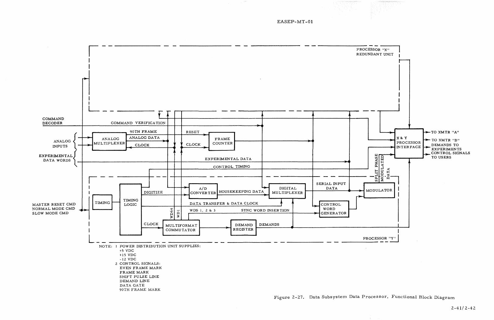
COMMAND DECODER
ANALOG { INPUTS
EX PER !MENTAL{ DATA WORDS
ER RESET CMD MAST NORM SLOW
AL MODE CMD MODE CMD
~
~~
EASEP-MT-01
I
I I L_ -- f - -- --
COMMAND VERIFICATION
90TH FRAME RESET
ANALOG ANALOG DATA FRAME MULTIPLEXER CLOCK
It CLOCK COUNTER
EXPERIMENTAL DATA
CONTROL TIMING
I -- -- -- - -I 1-- A/D ........ DIGITAL I DIGITIZE CONVERTER HOUSEKEEPING DATA MULTIPLEXER
TIMING
I I
L __ NOTE:
1-- TIMING LOGIC DATA TRANSFER
""' ..... WDS 1, 2 &t 3 ~
0 0 ;s: ;s:
CLOCK MULTIFORMAT COMMUTATOR
POWER DISTRIBUTION UNIT SUPPLIES: +5 VDC +15 VDC -12 VDC
2 CONTROL SIGNALS: EVEN FRAME MARK FRAME MARK SHIFT PULSE LINE DEMAND LINE DATA GATE 90TH FRAME MARK
&t DATA CLOCK + SYNC WORD INSERTION
DEMAND DEMANDS REGISTER
--'"
--SERIAL INPUT
DATA
........ CONTROL WORD r--
GENERATOR
PROCESSOR "X" REDUNDANT UNIT
--
Pi! Ul 0
~ Pi! 1:-<
p.. <: ....:! <:
1:-< :::;, 1:-< ....
r-
I I I
X&tY PROCESSOR INTERFACE
0 -~ 0. <:=:-1
Ul ~ 0
MODULATOR I ~ I
I I
_____ P_R_o_c_E_s~~ ·2:J
~
~
~
f-+-
TO XMTR "A"
TO XMTR "B" DEMANDS TO EXPERIMENTS CONTROL SIGNALS TO USERS
Figure 2-27. Data Subsystem Data Processor, Functional Block Diagram
2-41/2-42


ANALOG DATA INPUTS
ADVANCE PULSE FROM DATA PROCESSOR
HIGH RELIABILITY CHANNELS (1-15)
NORMAL CHANNELS (16-90)
SEQUENCER LOGIC
EASEP-MT -01
M u L T I p
L E X E R
ANALOG DATA TO
>--- PROCESSOR X A/ D CONVERTER
ANALOG DATA TO
l>--- PROCESSOR y A/ D CONYER TER
90TH FRAME
~------------------------------------~~PULSE TO FRAME COUNTER
Figure 2-28. Data Subsystem Analog Multiplexer/Converter, Block Diagram
Table 2-ll. Data Subsystem Timing and Control Pulse Characteristics in Normal PSEP Data Mode
Duration* Timing Relative to Pulse Type (fl. sec) Repetition Rate* Frame Mark
Frame mark 118 Once per PSEP Occurs at start of word frame of each frame
Even frame 118 Once every other In coincidence with mark frame frame mark 90th frame 118 Once every 90th In c oinc idenc e with mark frame frame mark Data gate 118 64, once per each Data gate of word 1 is (word mark) ten-bit word in in coincidence with
frame frame mark Data demand 9434 Once per experi- Occurs asymmetrically
ment word in PSEP frame
Shift pulse 47 640 pulses per frame 1060 pulses per second
Amplitude: High "or" logic ''1 "-+2. 5 to 5. 0 volts Low "or" logic "0"-0 to +0. 4 volts
(Figure 2-29)
Continuous 1060 pulses per second Symmetrical square wave
Rise and Fall Times: 2 to 10 fl. sec lOo/o to 90% points and 90% to lOo/o points
>:<In slow PSEP data mode, duration is twice the normal mode and repetition rate is one-hal£ normal mode.
2-43
l

2-44
1 2
X
9 10
-17 ~8
NA 25 26
-33 34
H 41 42
-49 50
NA 57 58
-WORD TOTALS
3 29 12 2
1
.!2 64
EASEP-MT -01
3 4 5 6 7
) X X NA X NA 11 12 13 14 '15
X - X - X NA 19 20 21 22 23
X NA X NA X NA 27 28 29 30 31
X - X - X NA 35 36 37 38 39
X • X • X NA 43 44 45 46 47
X - X - cv NA 51 52 53 54 55
X NA X NA X NA 59 60 61 62 63
X - X - X NA
LEGEND
x • CONTROL X • PASSIVE SEISMIC - SHORT PERIOD - • PASSIVESEISMIC-LONGPERIOD e · PASSIVE SEISMIC- LONG PERIOD TIDAL AND ONE
TEMPERATURE CV • COMMAND VERIFICATION (UPON COMMAND,
OTHERWISE ALL ZEROS) H • HOUSEKEEP lNG NA • NOT ASSIGNED (ALL ONES WILL BE TRANSMITIEDl
EACH BOX CONTAINS ONE TEN-BIT WORD TOTAL BITS PER FRAME • 10 X 64 • 640 BITS
8
X 16
X 24
X 32
X 40
X 48
X 56
NA 64
X
Figure 2-29. PSEP Telemetry Frame Format

PSEP WORDil
EASEP-MT-01
CONTROL WORD-FORMAT
PSEP WORD tz
PSEP WORDf3
Bit 1 2 3 4 s 6 7 8 9 10 11 12 13 14 15 16 17 18 19 20 21 22 Z3 24 25 26 27 Z8 29 30 11 1 1 0 0 0 1 0 0 1 0 0 0 0 1 1 1 0 1 1 0 11 Fl FZ F3 F4 F5 F~ M
~ BARKER CODE ---Mr-- COMPLEMENT OF BARKER CODE +FRAME COUNTER MODE (1, 2 .... 89, 0) BIT
PSEP Bit•/ Sample•/ Name Word• Ran&e Sample Second
DA-1 Barker Code and Complement 1, 2, and NA zz 1. 67 bit• 1 and 2 of word 3
DA-Z Fram• Collllt Bite 3 to 9 0-89 7 1. 67 inclu•ive of word 3
DA-3 Bit Rate ID Bit 10 of word 3 1/54
~ Mode Bit Meanin1
1 Normal data rate 2 Slow. data rate
DA-4 PSEPID Bit 10 of word 3 3 1/54
.!!:!!!!.! Mode Bit
3 ! (MSB)} 4 Data proce••or 5 10 nwnber
Figure 2-30. PSEP Telemetry Control Word Bit Assignments
complemented, is used to attain synchronization. The next seven bits provide frame identification for one through 90 frames for correlation of the analog multiplexer data. The 30th bit provides normal or slow mode information during the first two frames of the 90-frame sequence, and data processor serial number identification during the third through fifth frames of the 90-frame sequence. For the sixth through 90th frames the 30th bit has no information and reads logic zero.
2-46. Timing and Control Signals - Timing and control circuits provide synchronization signals for use throughout the PSEP.
The basic clock is a 169.6 KHz oscillator. A master flip-flop divides the clock frequency down to 84.8 KHz. The 84.8 KHz signal drives a divide-by-eight counter to obtain a 10. 6 KHz signal. This counter is gated to produce the 42. 4 KHz signal used in the slow data mode of 530 bps.
The 84. 8 KHz signal or the 42.4 KHz also drives a divide -by-ten counter. The outputs from this counter are used to drive the sub -bit counter and the timing logic. The sub-bit counter is a divide-by-eight counter with output frequencies of
2-45

\
EASEP-MT -01
1060Hz or 530Hz depending upon the operational mode. This output establishes the bit rate, drives a bit time counter, and provides timing signals for the timing logic.
The bit time counter is a divide-by-ten counter with an output frequency of l 06 Hz or 53 Hz which establishes the word rate. Outputs of this counter are used 1n generating the control words and signal timing throughout the processor.
The multiformat commutator determines the specific assignments of each word within the 64 word telemetry format. The commutator provides signals (demand pulses) of one word length and multiples of one word length in duration so that data may be gated from the experiments and command decoder through the splitphase modulator and into the transmitter in a predetermined sequence. The output of the multiformat commutator is applied to the demand register and the control word generator.
The demand register performs the following functions:
a. Provides memory for the demand signal while the commutator is being switched.
b. Acts as a master switch turning off all demands while allowing the format generator and all control signals to function normally while in active seismic mode.
c. Acts as a buffer between the demand decoder assembly eliminating any gating transients from the demand lines.
The control word generator generates the synchronization code and provides the information to the output register during the proper bit times of the control word. Mode, frame, and data processor serial number information is provided to the output register at the appropriate bit times.
The frame counter generates the frame bits. The frame counter is essentially a ripple-through counter which is advanced one step whenever the first word of each frame occurs. Reset is accomplished by means of the 9Oth frame end- of -frame signal generated by the analog multiplexer.
A flow chart of the data processor is presented in Figure 2-31.
2-4 7. DATA SUBSYSTEM TRANSMITTER
The data subsystem transmitter generates an S-band carrier frequency of 2276. 5 MHz which is phase modulated by the split-phase serial bit stream from the data processor.
2-48. Data Subsystem Transmitter Physical Description. Two identical transmitters are used in each data subsystem to provide standby redundant operation. Either transmitter can be selected to transmit downlink data. A transmitter is shown in Figure 2-32. Most circuit modules are mounted on a milled out magnesium base plate. Some modules and other components are located inside the base plate. Transmitter leading particulars are listed in Table 2-12.
2-46

N I
Oo!:o -.1 -N I
Oo!:o 00
f-zj ...... (1Q
~ t-1 ('!)
N I w ......
tJ Ill .-r Ill en g. UJ
'<; UJ
(ti a tJ Ill .-r Ill
'tJ t-1 0 () ('!) UJ UJ 0 t-1
f-zj ...... 0 ~ () ;:r' Ill t-1 .-r
START POWER ON
1 DATA PROCESSOR TURNS ON IN NORMAL MODE
NO
YES
TRANSMIT
FRAME COUNTER OUT OF SYNCHRONIZATION WITH THE ANALOG MULTIPLEXER
ERRONEOUS I• ,.. I DATA
YES
NO
HAS THE ANALOG MULTIPLEXER REACHED THE 90th CHANNEL
COLLECT AND TRANSMIT ONLY ACTIVE SEISMIC DATA AT A BIT RATE OF 10, 600 BPS
RECEIVED ACTIVE SEISMIC OFF COMMAND YES
NO
CONTINUE TRANSMITTING ACTIVE SEISMIC DATA UNTIL A SCHEDULED END OF FRAME FOR THE DATA PROCESSOR OCCURS
DATA PROCESSOR RETURNS TO LAST INSTRUCTED SLOW OR NORMAL MODE
l.
2.
NO
i YES
RECEIVED RESET COMMAND OR POWER RESET
INTERRUPT ACTIVE SEISMIC DATA TRANS-MISSION TRANSFER THE DATA PROCESSOR TO THE NORMAL MODE (1060 BPS)
TRANSMIT DATA IN THE NORMAL
~ MODE UNTIL AN END OF FRAME OCCURS
DID LOSS OF
,-----.4 START NEW DATA FRAME
l l. GENERATE AND
TRANSMIT CON-TROL WORD NO. 1
2. ADVANCE THE FRAME COUNTER
GENERATE AND TRANSMIT CONTROL WORDS NO. 2 AND 3
1 COLLECT AND TRANSMIT WORDS 4 TO THE HOUSEKEEPING WORD
1 START THE ANALOG TO DIGITAL CONVERSION OF THE HOUSEKEEPING DATA
j TRANSFER THE ANALOG TO DIGITAL HOUSEKEEPING DATA
I COLLECT AND TRANSMIT DATA FOR THE HOUSEKEEPING WORD AND WORDS THRU WORD NO. 63
l ADVANCE THE ANALOG MULTIPLEXER
l COLLECT AND TRANSMIT DATA FOR WORD NO. 64
J END OF FRAME
' I
SYNC OCCUR YES'YRAME
NO
L---., I
IS
TRANSFER THE DATA PROCESSOR TO NORMAL MODE (1060 BITS)
THE DATA !PROCESSOR
IN THE NORMAL !NO MODE?
YES
1 1. CONTINUE IN PRESENT MODE UNTIL END OF FRAME OCCURS
2, DATA PROCESSOR EXECUTES THIS COMMAND AT THE END OF THE DATA FRAME ONLY
TRANSFER THE DATA PROCESSOR TO THE SLOW MODE (530 BPS)
TRANSMIT ERRONEOUS DATA IN NORMAL MODE UNTIL 90th FRAME OCCURS
NO IS THE DATA PROCESSOR IN THE SLOW MODE
YES
1. CONTINUE IN PRESENT MODE l. INTERRUPT
UNTIL END OF THIS FRAME
FRAME OCCURS OF DATA
2.DATA PROCESSOR 2. POWER IS
EXECUTES THIS SWITCHED
COMMAND AT TH TO DATA
END OF THE PROCESSOR
DATA FRAME REDUNDANT
ONLY UNITS
1 . CONTINUE IN PRESENT MODE UNTIL END OF FRAME OCCURS
2. DATA PROCESSOR EXECUTES THIS COMMAND AT THE END OF THE DATA FRAME ONLY
YES
NO NO NO ~----'(.
V V V RECEIVED DID POWER RECEIVED RECEIVED SLOW RECEIVED ACTIVE INO RESET OR RESET NORMAL MODE COMMAND POWER SEISMIC ON COMMAND OCCUR MODE COMMAND DURING THIS SWITCHING COMMAND DURING THIS DURING THIS DURING DURING FRAME FRAME FRAME THIS FRAME THIS
FRAME
NOTE:
ACTIVE SEISMIC NOT USED FOR PSEP
M > en M 'tJ I
~ f-1 I 0 1-'


EASEP-MT-01
Figure 2-32. Data Subsystem Transmitter
2-49. Data Subsystem Transmitter Functional Description. Figure 2-33 shows a block diagram of the transmitter circuit. Transmitter output frequency is a function of the oscillator crystal and tuning. An oscillator frequency of 142 MHz is used as an example in this discussion. The crystal-controlled oscillator in the oscillator-buffer-phase modulator generates a 142 MHz frequency which is phase modulated by the binary data from the data processor. A buffer amplifier between the 142 MHz oscillator and the phase modulator provides impedance matching and circuit isolation which enhance modulator stability. The analog phase modulator contains a pair of back-to- back varactor diodes which vary the capacitance of a parallel resonant tank circuit by varying the diode back bias at the modulating frequency. A modulator driver maintains the proper diode bias voltages for binary modulation voltage variations from 2. 5 volts to 5. 5 volts peak-to-peak.
2-49

EASEP-MT -01
Table 2-12. Data Subsystem Transmitter Leading Particulars
Characteristic
Output frequence Frequency stability
Output power
Output spurious
Incidental AM Phase noise
Carrier deviation
Modulation drive
Modulation polarity Modulation frequency Modulation input impedance
Supply voltages Supply power
Telemetry outputs
Weight Form factor
Value
2276. 5 MHz (a)±. 0025%/year (long term) (b) 2. 2 x lo-10 parts/second (short term) l watt minimum into 50 ohm load with maximum VSWR of l. 3:1 (a) Harmonically related: 0 dbm, 2-7 GHz (b) Other: -50 dbm above 2-GHz -10 dbm,
7-10 GHz (c) All: 0 dbm below 2 GHz Less than 3o/o (0. 25 db power ratio) Less than 4. 5° rms as measured with a phase coherent receiver having a loop bandwidth 2 BL = 50 cps Fixed at ± l. 25 radians ± 5o/o
+2. 5 to +5. 5 volt peak-to-peak (binary voltage only) + phase shift for +modulation voltage 200Hz to 12KHz/binary voltage 22K ohm minimum shunted by less than l 00 pf (ac coupled) +29 vdc ± l o/o + 12 vdc ± l o/o 9. 5 watts maximum (9. 2 watts nominal = 8. 7 w @ + 2 9 v + 0. 5 watts @ + 12 v) (a) Oscillator crystal temperature (b) Heat sink temperature at highest power
stage (c) RF level at output (AGC voltage) (d) Supply current to power doubler 1. 13 pounds 7. 5 x 2. 0 inches mounting surface x l. 50 inches in height exclusive of connectors
The output of the phase modulator is applied to buffer amplifier, AGC-controlled amplifier, and frequency doubler stages. The buffer amplifier stage between the phase modulator output and the AGC-controlled amplifier inputs prevents modulator tank circuit detuning which would be caused by amplifier input impedance changes resulting from temperature and aging. The times two frequency multiplier stage increases the carrier frequency to 284 MHz.
The 284 MHz output from the frequency multiplier is amplified by the power amplifier, and doubled in frequency by the power doubler. A times four varactor frequency multiplier then quadruples the carrier frequency. The output frequency of 2276.5 MHz is generated by the crystal-controlled oscillator. A stripline
2-50

N I (Jl ......
+29 v
+29 v
+30. 5 dbm t- --
29 v RTN.
0+12 v
• ~CURRENT SUPPLY TLM
---..... ~HEAT SINK TEMP. TLM
rr-- ---- -:--~
POWER I VARACTOR STRIPLIN£ 1 WATT X2 X4 FILTER
AMPL. I .._ ___ _.I 12276. 5 MHz
L_. __ _ +34. 5 dbm +30. 5 dbm OUTPUT -- - - ::.:.:..J - _ _ __J± 1. 25 RAD.
~ ......... ONTROLLE AGC FILTER, MPL. DETECTOR, AMPL.
+12 v
+10 v c
I +
12 vI BUFFER I AMPL. I
_ _J +4 dbm ...,
MODULATOR I DRIVER ~-MOD.
I l+lOV
2. 5 v to1
5. 5 v r5 dbm
BINARY INPUT I --.....11..-.1..MODULATION
+12 v
+29 vo +10 v
AGC VOLTAGE {Pwr Out) TLM
VOLTAGE FROM I osc. & XTAL TEMP. DATA PROCESSOR BUFFER TLM
-18 v
BIAS SUPPLY
+lOV
l
+29 v +10 VDC POWER REGULATOR
"""'
+12 v ...i'll
-""
I AMPL. NOTE: 1 POWER DISTRIBUTION UNIT SUPPLIES +12 VDC and+ 29 VDC·
L.:- _ -~ 2 ENGINEERING STATUS TELEMETRY SIGNALS TO DATA PROCESSOR.
Figure Z- 33. Data Subsystem Transmitter, Block Diagram
M ~ [j)
M 1j I
~ J--3 I
0 .......

EASEP-MT-01
filter reduces spurious harmonics of the output signal to 30 db below the carrier. Additional spurious rejection is provided by the interfacing diplexer. A directional coupler built into the filter provides an RF output to the AGC circuit.
Monitor circuits provide analog signals to the data processor indicating the status of current supply, AGC voltage and the temperatures at the oscillator crystal and the power heat sink.
2-50. DATA SUBSYSTEM POWER DISTRIBUTION UNIT
The power distribution unit (PDU) distributes power to experiment and central station components and provides circuit overload protection and power switching of selected circuits. The PDU also provides signal conditioning of selected central station monitor signals prior to input to the analog multiplexer for analogto-digital conversion and subsequent data transmission to earth.
2-51. Data Subsystem Power Distribution Unit Physical Description. A PDU is shown in Figure 2-34. The power distribution unit is comprised of five printed circuit cards, a mother board to provide interconnection between the individual boards, the component connector, a case, and a cover. All electrical inputs are made through a rectangular, screw-lock, 244-pin connector.
Figure 2-34. Data Subsystem Power Distribution Unit
2-52

EASEP-MT-01
The amplifier board m.ounts six sensing bridges and amplifiers, the power reserve sequencer comparator, and one experiment power control circuit.
The experiment drive card contains the relay driver, relays, fuses, and associated circuit components for the power control of five experiments (only one of which is functional).
The signal conditioning and logic card comprises the resistive dividers used for thermistor temperature sensing, nickel wire temperature sensing and voltage monitoring. Additionally, the required gates, flip-flops, and gate expanders used for counting and decoding in the reserve power sequencer, are mounted on this card.
The central station power control card provides mounting for the relays, drivers, and circuit overload sensing relays associated with the transmitter, receiver, data processor, power dissipation module load No. 1 and No. 2, and backup heater power control.
Circuitry for the dust detector electronics is mounted on a single card. Leading particulars of the power distribution unit are listed in Table 2-13.
Table 2-13. Data Subsystem Power Distribution Unit Leading Particulars
Characteristic Value
Form factor: 2. 8 X 4. 0 X 7. 25 inches Weight: 2. 4 pounds Power consumption: 1. 75 watts DC input voltages: +29 vdc
+ 15 vdc +12 vdc +5 vdc -6 vdc -12 vdc
2-52. Data Subsystem Power Distribution Unit Functional Description. The functional description of the power distribution unit is divided into three major functions:
a. Power-off sequencer b. Temperature and voltage monitor circuits c. Power control to experiment and central station.
Figure 2-35 shows a block diagram of the PDU.
2-53. Power Off Sequencer - The power off sequencer of the PDU detects mmlmum reserve power and sequentially turns off up to three preselected experiments to bring the power reserve within acceptable limits. The minimum reserve power is detected by monitoring the voltage across a power conditioning unit resistor. This voltage is applied to an operational amplifier used as a level detector. An RC delay network is employed at the output of the level detector. The output of the
2-53

EASEP-MT-01
delay is applied to a second level detector which drives the power-off sequencer logic. This arrangement turns on the power- off sequencer logic input gate when the reserve power drops below acceptable levels.
The power-off sequencer logic input gate passes a 1 KHz clock signal to a fivestage binary counter. The counter accumulates the l KHz count until the reserve power becomes greater than the minimum level. The counter output is fed to decoding gates which sequentially turn off up to three preselected experiments.
The sequencer decoding gates are connected so that upon turn-on of the logic input gate, an output ground level signal is provided during the count between l and 9 milliseconds to the experiment No. 4 standby-on relay driver. This relay removes experiment prime power and applies power to the standby line. If the IPU overload persists, the ground level signal supplied to the experiment No. 4 standby line is removed and a ground level signal is applied to the experiment No. 3 standby-on command input during the next 8-millisecond period (when the count is between 9 and 17 milliseconds). The sequencer could continue in the same manner until a third experiment (No. l) is in the standby mode if overloading persists. If, however, the overload is removed within the sequence, the counter will be reset when a satisfactory power reserve signal is obtained. On PSEP there is one experiment, the PSE, connected to No. l position.
2-54. Temperature and Voltage Sensor Circuits - Each thermistor temperature sensing network consists of a 3010 ohm, one percent resistor in series with a 15K ohm (25°C) thermistor and a second 3010 ohm resistor to ground. The divider excitation is 12 vdc. The output is taken across the 3010 ohm resistance connected to ground. The resultant output, although not perfectly linear over the -50°F to +200"F temperature span of measurement, provides an output measurement with very low dissipation of power. The maximum sensor current is less than 2 milliamperes.
The nickel wire temperature sensors (2000 ohms at the ice point) are used in dividers to monitor exposed structural temperature, multilayer bag insulation temperatures, and solar panel temperatures. The circuit is a simple divider consisting of 12 vdc supplied through 5900 ohms and the sensor to ground. The output analog signal is taken across the sensor, providing a reasonably linear response from -300°F to +300°F. The maximum current through the sensor is less than 2 milliamperes.
Voltage monitors are provided for each of the six voltage outputs of the power conditioning unit. The positive voltages are monitored with resistive dividers with an output impedance less than lOK ohms. The two negative voltages lines are also monitored by dividers. The 29-vdc supply is used as a bucking voltage to a positive output of 0 to 5 vdc as required by the multiplexer. The output impedance is less than l OK ohms.
2-55. Power Control - Four transistorized relay drivers, magnetic latching relays, and one magnetic latching relay acting as an overload sensor (circuit breaker) perform the control and circuit breaking function for each experiment prime power line. The experiment standby power line is fused at 500 ma. and has no reset capability. Spike suppression and steering diodes are also
2-54

+l9 VDC FROM PCU
CMD,EXPNO.I ON
CMD,EXP NO I STANDBY ON
;MD, EXP, NO. Z ON
CMD, EXP NO. Z SATNDBY ON '
,, CMD, EXP NO.3 ON
CMD EXP NO. STANDBY ON '
1' CMD, EXP NO. 4 ON
CMD, EXP NO. STANDBY ON
CMD,EXP NO. ON
4
s, /
CMD ON)-- --1 DRIVER
CMD,OFF )-- --I DRIVER
CMD,ON
CMD,OFF '-
CMD,ON >-- H'DRIVER
CMD,OFF )-- --I DRIVER
DRIVER
l DRIVER
DRIVER
1 DRIVER
DRIVER
1 DRIVER
DRIVER
I
T DRIVER
DRIVER
CMD, EXP NO. STANDBY ON
5>-·
l DRIVER
CMD, EXP NO. SATNDBY OFF
I
.z)--CMD, EXP NO STANDBY OFF
~DRIVER
lDRIVER
L--{~ DRIVER
DRIVER
-, RELAY
I
DRIVER~
RELAY
DRIVER }---J
RELAY
I
I RELAY CKT BKR
1 RESET' I I I TRIP I
I RELAY CKT BK_R.
l RESET I I TRIP I
I I RELAY F-lcKT BKR
1 RESET I I I TRIP I
I I RELAY HCKT BKR
I RESET I I I TRIP I
I RELAY CKT BK
1 RESET 11 I TRIP [
L--{ RELAY
L--{ RELAY
CMD, EXP NO. STANDBY OFF
3 ~ L_____f RELAY
CMD. EXP NO. STANDBY OFF
.)
5' CMD, EXP NO. STANDBY OFF ,?
I I
DRIVER L--§AY
~~ ,--· DRIVER L-{ RELAY
DRIVER_j
BACKUP'
+5VDC FROM l)-CONVERTOR (PCU)
' HTR -llVDC FROM ' CnOIVERTOR !PCU) +Izvnc FRoM '
/ PDM LOAD CONVERTOR (PCU)
NO. I
CMD DATA PROC
)PDM LOAD "X" ON /
NO. Z +15VDC FROM CONVERTOR (~U)/
CMD DATA PROC "Y"ON TIMER INPUT
FROM CMD DEC /
CMD XMTR "A" '-SELECT
CMD XMTR ON
CMD XMTR OFF /
CMOXMTR "B" /
T SELECT , TO EXP NO.I
' /' +Z9 VDC
-6VDC FROM ' CONYER TOR(~ UtY
_' T9 EXP NO. Z /
+Z9 VDC
TO EXP NO.3 +Z9 VDC
'TO EXP N0.4 +Z9 VDC
i TO EXP N0.5
+l9 VDC
FUSE
I _'\.EXP'T NO.1 STBY PWR
FUSE
----7 EXP'T NO, Z STB'Y PWR
FUSE
l EXP'T NO.3 STB'Y PWR
FUSE ...
l EXP'T N0.4 STB'Y PWR
F~SE
L EXP 1T NO.5 STB'Y
PWR
rlDRIVER~-
RELAY (DPDT)
K DRIVER '1.--
DRIVER r.-RELAY (DPDT)
DRIVER 1-L___ DRIVER~
RESET
DRIVER
DRIVER~~
RELAY (DPDT)
DRIVER ~'---
DRIVER
T DIVIDER
DIVIDER
DIVIDER
DIVIDER
DIVIDER
DIVIDER
DIVIDER
DIVIDER
-
EASEP-MT-01
TO AID CONVERTOR ''X" -IZ VDC
,TO A/D CONVERTOR "Y" -12 VDC TO AID CONVERTOR
I ' ''X" +SVOC TO PROCESSOR ''X" +5 VDC
,'TO AID CONVERTeR r +15 VDC
-)TO A/D CONVERTeR +15 VDC
TO PROCESSOR "Y''
T +SVDC , TO A/D CONVERTOR
I /"Y" +5VDC
CKT BKR +lZVDC TO
I RECEIVER
TO CMD REG HEATER +IZ VDC.
·TO TRANSMITTER HEATER +29VDC
~HCKTBKR TO XMTR "A" +Z9 VDC
HCKTBKR , TO XMTR "A"
RELAY +12 VDC
(DPDT) HcKT BKR , TO XMTR "B" r + Z9 VDC
~HCKTBKR ,_TO XMTR "B"
l /+lZ \'9C ' TO D I'PLEXER
+lZVDC TRIP
TRIP
(-6 VDC MONITOR) ,TMOUTPUT TO ANALOG MULTIPLEXER
},.'TO COMMAN-D DEcODER -6 VDC
(+5 VDC MON!TCR) ''TM OUTPUT TO /1ANALOG MULTIPLEXER
TO CMD DECODER (CONT.) +5VDC
,.TO MULTIPLEXER +5VDC
'TO FRAME CTR +5VDC (+15 VDC MONITOR)
----7!~A'i.~p~~LT~PLEXER -----)TO MULTIPLEXER
-IZVDC (-IZ VDC MONITOR) TM OUTPUT TO ANALOG MULTIPLEXER TO RECEIVER
r -6VDC (+IZ VDC MONITOR) TMOUTPUT TO
/ ~NALOG M!JLTIPLEXER TO MULTIPLEXER
/ +IZVDC TO CMD DECODER
/ +IZVDC (+ Z9 VDC MONITOR) ·TMOUTPUT TO
<ANALOG MULTIPLEXER (PDU INTERNAL TEMP.) ._:TM OUTPUT OT
ANALOG MULTIPLEXER (PDU BASE TEMP.) ,. TM OUTPUT TO .
, ANALOG MULTIPLEXER
r-"' SUMMING NETWORK
OUTPUT TO > MULTIPLEXER
SUMMING _.... NETWORK
"
STRUCTURE TEMP. ~ N0.4 (TM)
SOL PANEL TEMPr----1 DIVIDER! NO.I (TM)
)
SOt~~7~~) TEMP) [piviDER I ) STRUCTURE TEMP>-----1 DI IDER I
NO.I (TM) V )
STRUCTURE TEMP) jmviDE~ NO. Z (TM)
STRUCTURE TE:MP~~ ) NO. 3 (TM) .
THERMAL PLATE IDIVIDER~ TEMP NO. I (TM) ) T~ERMAL PLATE >-----1 I ) T MP NO. Z(TMl DIVIDER
THERMAL PLATE) TEMP NO.3 (TM)
I DIVIDER~ THERMAL PLATE >-------1 DIVIDER I TEMP NO.4 (TM)
) THERMAL PLATE) JmviDERj-------) TEMP NO. 5 (TMl
INNER INSULATION)-------j DIVIDER I ) TEMP.
~~~;~INSULATION) I DIVIDER f----------7 CMD DECODER vco >---1 DIVIDER I TEMP (TMl ·
) CMD DECODER !NT '- ~ TEMP (TMl .
~~ED;E~g~~l )-------1 DIVIDER I ) DATA PROCESSOR )
lmviDER f----7 ''X" !NT TEMP Jt™l DATA PROCESSO >-----1 I ) ''X" BASE TEMP {TMJ DIVIDE~
gx~~ ~'t'i.tN~~~M)) I DIVIDE!!- f----7 DY!'IATRONICS,_ >-------1 DIVIDER I INT. TEMP (TM) -
)
I KC CLOCK.
POWER LEVEL ~y.f. POWER SENSE FROM PCU TURN OFF
REF. SEQUENCER COMPARATOR
REFERENCE
{ SENSOR IDUST DETECTOR INPUTS ELECTRONICS
CMDON"- T I CMDOFF
<OUTPUTS TO MULTIPLEXER
POWER TO SENSORS
,\TO ANALOG ,; J MULTIPLEXER
Figure 2-35. Data Subsystem Power Dis tri buti on Unit, Bloc k Diagram
2-55/2-56


EASEP-MT-01
incorporated. The steering diodes provide isolation between command lines and astronaut control lines (not used) where required. Three command inputs are provided for each experiment power control circuit as follows:
a. Experiment operational power-on command b. Standby power-on command c. Standby power-off command.
The three command inputs operate one or both of two power switching relays, depending on the command received. One relay provides the selection of either standby power or operational experiment power. The other interrupts the standby power line. The receipt of an experiment operational power-on command will transfer the power select relay to a position which provides power through the current sensing coil of the circuit breaking relay to the experiment electronics. A separate manually operated switch is provided to supply the experiment ope rational power-on command for each experiment in the event of uplink failure. 1\
second command (standby power-off) operates the relay coil of the standby power interruption relay to open the circuit supplying power to the standby line. The standby power-on command, however, operates on both relays. The standby power-on command closes the selector relay contacts supplying power to the standby power relay contacts and also closes that relay's contacts so that pov;!(:r 1s
applied to the standby line. If the selector relay is in the position which supplies operational power to the experiment power line and the standby power interruption relay contacts are closed, two commands must be initiated to interrupt all power to an experiment. These commands are the standby power-on command followed by standby power-off command.
Circuit breaker operation is provided by internally generating a standby- on command using the contacts of a current sensing relay. Should an overcurrent condition exist through the sensing coil in series with the experiment operational power line, the contacts of the sensing relay break the normal standby-on command line and apply a ground signal to each of two relay drivers. One relay driver operates the power select relay to the standby-on position. The other driver operates the standby power interruption relay to close the contacts supplying power to the standby power line. Operation of the standby power interruption relay provides power to the reset coil of the overload sensing relay thereby resetting its contacts to permit normal standby-on command inputs. Provisions have been made to shunt each current sensing coil to provide a 0. 5 amp capability to all experiments.
A high conductance diode is paralleled (in a forward biased condition) with the current sensing coil of the overload sensing relay. This diode permits an extension of the dynamic range of the overload sensor to high transient overloads. Two resistive summing networks provide a telemetry output to indicate the presence or absence of standby power for all experiment power switching circuits.
2-57

EASEP-MT -01
Transmitter power control and overload protection as shown in Figure 2-36 uses two power control relays, four overload sensing relays, and associated relay drivers. Four commands are required:
a. Transmitter on b. Transmitter off c. Transmitter A select d. Transmitter B select.
SELECT A CMD.
MASTER ON CMD.
+IZV.
+29V.
MASTER OFF CMD
SELECT B CMD.
.....
-.....
.....
,..
J l
I L
J l
J I
TRIP
DRIVER :
DRIVER l--+ TRANSMITTER ON/OFF RELAY (Dpdt}
DRIVER 1-DRIVER I
I TRIP
I--
TRANSMITTER TRANSFER RELAY (Dpdt}
1--
720 ± 30 DAYS
rl CKT. BKR. r .....
trlCKT.BKR.L ..... -
~CKT.BKR.E _..... - -
ycKT.BKR.L
[
+29V TO XMTRA
+IZV TO XMTRA
+29V TO XMTRB
+IZV TO XMTR B
+IZV TO DIPLEXER
..... ~TI:~ - -RETURN RETURN
Figure 2-36. Data Subsystem Transmitter Power Control
The transmitter on and off commands operate the double -pole, double -throw relay which switches both 12 vdc and 29 vdc to the transmitter transfer relay. Twopower lines to either of two transmitters are selectable via transmitter A or transmitter B select commands as appropriate. If either power line to either transmitter is overloaded, the contacts of the overload sensing relay transfers the transmitter select relay to supply power to the alternate transmitter. When power is transfer red to the alternate transmitter, the circuit overload sensing relays are both reset and the normal command link inputs are restored. Diplexer switching power, required only when transmitter B is selected, is obtained directly from the 12 vdc transmitter power line.
2-58

EASEP-MT-01
The command receiver requires both 12 vdc and -6 vdc for operation (Fig-ure 2- 37). The -6 vdc line is not provided with circuit protection because of the high reliability of the -6 volt line load. The 12 vdc line is provided with overload protection which uses a magnetic latching circuit breaker relay. The sensing coil of this device will interrupt the 12 vdc of the receiver when current is excessive. Since no redundancy of receivers exists, a 12-hour reset pulse is supplied to the breaker every 12 hours. If the receiver is tripped off, a receiver heater load is energized by the transfer of the circuit breaker contacts to maintain thermal balance.
For data processor power control (Figure 2-37 ), redundant electronics are switched using standard magnetic latching relays. These relays are controlled by standard commands. Overload protection is not provided.
Power dissipation resistor 1, and power dissipation resistor 2 of the power dissipation module are switched off and on by ground command only.
Electronics for the dust detector are mounted on a printed circuit card in the PDU and consist of the following three functional areas:
a. Power switching b. Operational amplifiers c. Temperature measurement.
The power switching function switches 12 vdc and -12 vdc power to the amplifiers upon receiving a ground command. Power protection for the card is provided by individual fuses on each of the two voltages.
The operational amplifier consists of an integrated circuit differential amplifier with added circuitry to establish a closed loop fixed gain configuration. Its functiona! purpose is to condition the output of the photocell detectors, which act as variable current sources of a 0 to +5 vdc varying de level for telemetry information. Temperature measurement is accomplished with a thermistor attached to the photocell and a series resistor, located on the card to optimize thermistor sensitivity and provide a 0 to +5 vdc telemetry signal.
2-59
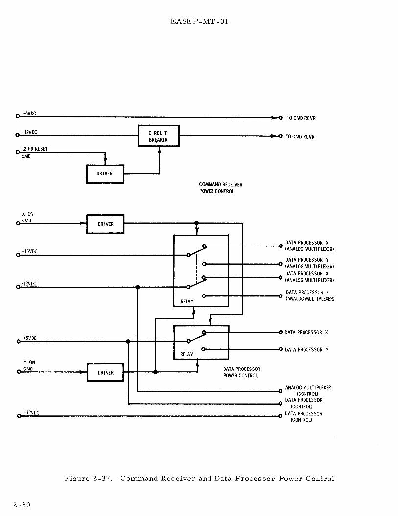
-6VDC
- +12VDC CIRCUIT BR~AKER
.... 12 HR RESET CMD t
I DRIVER I I
X ON CMD
DRIVER
.... +15VDC
.... -12VDC
+SVDC
Y ON .... CMD
DRIVER
EASEP-MT-01
... l
- I - I I I I I I
.....
RELAY
• RELAY
t
COMMAND RECEIVER POWER CONTROL
---
t
DATA PROCESSOR POWER CONTROL
-
----
-
-,..
TO CMD RCVR
TO CMD RCVR
DATA PROCESSOR X (ANALOG MULTIPLEXER)
DATA PROCESSOR Y I ANALOG MULTI PLEXERl DATA PROCESSOR X lANA LOG MULTI PLEXERl
DATA PROCESSOR Y (ANALOG MULTIPLEXER)
DATA PROCESSOR X
DATA PROCESSOR Y
ANALOG MULTIPLEXER ICONTROU
DATA PROCESSOR ICONTROU
+12VDC DATA PROCESSOR ICONTROU
Figure 2-37. Command Receiver and Data Processor Power Control
2-60

EASEP-MT -01
2-56. PASSIVE SEISMIC EXPERIMENT
The passive seismic experiment (PSE) is designed to monitor seismic activity, and it affords the opportunity to detect meteoroid impacts and free oscillations. It may also detect surface tilt produced by tidal deformations which result, in part, from periodic variations in the strength and direction of external gravitational fields acting upon the Moon, and from changes in the vertical component of gravitational acceleration.
NOTE
The detection of tidal motion is not a requirement for PSEP because the PSE is mounted on the central station. The seismometer tidal outputs will be used by the PSE for leveling the seismometers.
Analysis of the velocity, frequency, amplitude, and attenuation characteristics of the seismic waves should provide data on the number and character of lunar seismic events, the approximate azimuth and distance to their epicenters, the physical properties of subsurface materials, and the general structure of the lunar interior.
In the lower frequency end (approximately 0. 004 to 3. 0 Hz) of the PSE seismic signal spectrum, motion of the lunar surface caused by seismic activity is to be detected by tri-axial, orthogonal displacement amplitude type sensors. These sensors and associated electronics comprise the long period (LP) seismometer. In the higher frequency end (approximately 0. 05 to 20 Hz) of the PSE seismic signal spectrum, vertical motion of the lunar surface caused by seismic activity is to be detected by a one-axis velocity sensor. This sensor and associated electronics comprise the short period (SP) seismometer.
Two separate outputs are produced by each axis of the LP seismometer. The primary output is proportional to the amplitide of low frequency seismic motion and is referred to as the seismic output. The secondary output is proportional to very low-frequency accelerations and is referred to as the tidal output. The tital output in the two LP horizontal axes is proportional to the amount of local tidal tilting of the lunar surface along these axes, as indicated by changes in de signal level. The tidal output in the LP vertical axis is proportional to the change in the lunar gravitational acceleration as determined by that axis, again as related to changes in de signal levels. The SP seismometer yields a seismic output proportional to seismic motion in the vertical axis of the instrument.
Electronics associated with each seismometer amplify and filter the four seismic and three tidal output signals. These seven signals are converted by the PSE subsystem to digital form, and released upon receipt of a demand pulse to the PSEP data subsystem for transmission to Earth. The temperature of the PSE sensor assembly is monitored and provided as the eighth PSE digital data output. Each PSEP telemetry format contains 64 words; 43 are used to transmit the eight PSE scientific data output signals to the MSFN stations on the Earth. In addition, eight
2-61

EASEP-MT -01
analog signals conveying engineering data from eleven sources in the PSE are routed over separate lines to the PSEP data subsystem, multiplexed into the PSEP housekeeping telemetry word (No. 33), and transmitted to Earth to permit PSE status to be monitored.
Initiation and control of certain PSE internal functions is accomplished by 15 discrete commands relayed from Earth through the PSEP data subsystem.
2-57. PSE PHYSICAL DESCRIPTION
The PSE (Figure 2 -38) comprises three major physical components. The sensor assembly and thermal shroud are mounted on top of the mounting plate. A separate electronics assembly is located in the PSEP central station, and provides the electrical interface with the data subsystem.
2-58. PSE Sensor Assembly. The sensor assembly is generally cylindrical in form, and is fabricated principally of beryllium to achieve light weight and long term stability. The long period (LP) and short period (SP) seismometers, the sensor leveling platform, the caging mechanism, and associated electronics are contained in the sensor assembly. The principal structural elements of the sensor are the base and the gimbal-platform assembly on which the LP seismometer is mounted. The LP seismometer comprises three orthogonally oriented, capacitance type seismic sensors; two horizontal axes and one vertical axis.
Each of the LP horizontal axis sensors comprise a 1. 65 -pound mass mounted on the end of a horizontal boom. The boom and mass assembly is suspended from the sensor frame so that it is free to rotate through a very limited portion of the horizontal plane in the manner of a swinging gate. Inertia of the mass causes it to tend to remain fixed in space when motion of the supporting frame occurs due to seismic motion of the lunar surface. The capacitance type transducer attached to the inertial mass produces an output proportional to the amount of displacement of the frame with respect to the mass. The LP vertical axis sensor differs from the horizontal sensors in that the boom-mounted mass is suspended from the frame by a zero length spring. The spring is adjusted so that the weight of the boom/mass assembly is compensated by the spring tension.
The LP leveling platform is gimballed through Bendix flexures, and is positioned by leveling motors along two horizontal axes. This permits leveling of the LP seismometers to within three arc -seconds of level. Independent positioning of the sensor in the LP vertical axis to the same tolerance is provided by a separate leveling motor which adjusts the tension of the suspension spring.
The SP seismometer is a single -axis device containing one vertically mounted, coil-magnet type seismic sensor mounted directly to the base of the sensor assembly. Leveling of the SP seismometer is accomplished by leveling the entire assem.bly, eliminating the need for separate internal leveling devices.
2-62

EASEP-MT -01
Figure 2-38. Passive Seismic Experiment Subsystem
Caging is provided by a pressurized bellows. When pressurized, pins are inserted into each inertial mass, raising the mass and thereby unloading the suspension system of each sensor. Pressure in the caging mechanism is released by firing a piston actuator by Earth command, after departure of the LM, to uncage the sensors and free them for operation.
The seismometer electronics are contained in part in the sensor assembly and the remainder is located in the PSEP central station. In the sensor, four printed circuit board subassemblies are mounted in the base, surrounding the SP seismometer. These subassemblies provide circuitry associated with amplification demodulation, and filtering of the outputs of each of the four seismic sensors. In addition, the sensor electronics provide for LP sensor leveling, and sensor assembly temperature monitoring and heater control. The heater control circuits regulate power to a heater located .in the base of the sensor assembly to compensate for loss of thermal energy.
2-59. PSE Thermal Shroud. The thermal shroud has the shape of a flat-crowned hat. The crown portion covers the sensor, while the brim portion is secured to the mounting plate with velcro. The shroud is made of 20 layers of aluminized mylar, separated by alternate layers of silk cord, and wound on a perforated, aluminum support. The shroud covers the sensor assembly and the adjacent mounting plate to aid in stabilizing the temperature of the sensor assembly. A ball level and a sun compass are provided on the top surface of the shroud for leveling and azimuthal alignment of the PSEP.
2-63

EASEP-MT -01
2-60. PSE Electronics Assembly. The PSE central station electronics (CSE) module is located in the PSEP central station. Eleven printed circuit board subassemblies are contained in the CSE which provide the command logic circuits for the fifteen commands regulating or controlling the PSE internal functions. Also, the CSE contains circuitry associated with attenuation, amplification, and filtering of the seismic signals, processing of the PSE scientific and engineering data outputs, and its internal power supplies. The CSE is physically and thermally part of the central station, but electrically and functionally part of the PSE.
2-61. PSE Leading Particulars. Table 2-14 lists the physical characteristics and power requirements of the PSE and the performance characteristics of the eight PSE scientific data channels.
2-62. PSE FUNCTIONAL DESCRIPTION
The PSE instrumentation employed to detect seismic disturbances in the lunar surface is functionally divided into three long period seismic data channels, three tidal data channels, one short period seismic data channel, and a sensor assembly temperature monitoring channel. These scientific data channels are supported by sensor assembly heater control, data handling, uncaging and leveling, and power functions. (See Figure 2-39.)
Table 2-14. PSE Leading Particulars
Characteristic Value Physical Data
Sensor Assembly, including Thermal Shroud:
Height 15.25 inches Diameter 11. 75 inches Weight 20. 9 lbs.
Sensor l8.3lbs. Thermal Shroud 2.4lbs.
Central Station Electronics: Height 2. 75 inches Width 7. 25 inches Depth 6.5 inches Weight 4. 1 lbs.
Power Requirements
Analog Electronics 1. 61 watts Digital Electronics 1. 21 watts Power Converter Loss 1. 71 watts Heater 2. 50 watts Level System 3. 60 watts
Functional Power and Heater 7. 03 watts Functional Power and Level 8. 13 watts Voltage 29.0 ± 0.58 vdc
2-64

EASEP-MT -01
Table 2-14. PSE Leading Particulars (cont)
Characteristic Value Scientific Data Signal Characteristics
Dynamic Range: SP and all LP seismic signals Sensor as sen1bly temperature
Sensitivity at Maximum Gain: SP and all LP seisrr1ic signals Sensor assen1bly tcn1perature
Frequency Response: SP seismic signal (0 db= 5 v/J.L, maximum gain)
All LP seismic signals (0 db = 0. 5 v/ p., feedback factor = -33. 1 db, post-amplified gain = 1)
All LP tidal output signals
Sensor assembly temperature
1-1 =micron m 1-1 = millimicron v /1-1 = volts per micron
1. 0 mp. to 101-1 0. 02o to 20oC
5. 0 v/ 1-1 0. 25 v/oC
-40 db @ 0. 038 sec. +42 db/ oct. 0. 038 to 0. 1 sec. +20 db @ 0. 1 sec. -6 db/oct. 0. 1 to 1. 0 sec. -18 db/oct. I. 0 to 20 sec. -78 db@ 20 sec. -60 db@ 0. 3 sec. +48 db/oct. 0. 3 to 0. 7 sec. 0 db 0. 7 to 15 sec. -12 db/oct. 15 to 100 sec. -18 db/oct. 150 to 250 sec. -60 db @ 250 sec. -74 db@ I. 2 sec. +6 db/oct. l. 2 to 15 sec. -52 db@ 15 sec. -6 db/oct. 15 to 150 sec. -72 db@ 150 sec. -12 db/oct. 150 to 750 sec. 100 db @ 750 sec. 107- 143°F ± 1o/o
Control is achieved through 15 separate ground command channels governing the follO\\'ing:
a. Signal calibration and gain in the four seismic data channels b. Filtering in feedback circuits in the three long period channels c. Le\-eling and uncaging of the PSE seismometers d. Sensor assembly heater.
The commands are discrete (on-off or sequential stepping) and are transmitted from MSFN stations on the Earth, through the PSEP data subsystem. A discussion of these commands and their basic functions is provided in paragraph 2-65.
2-65
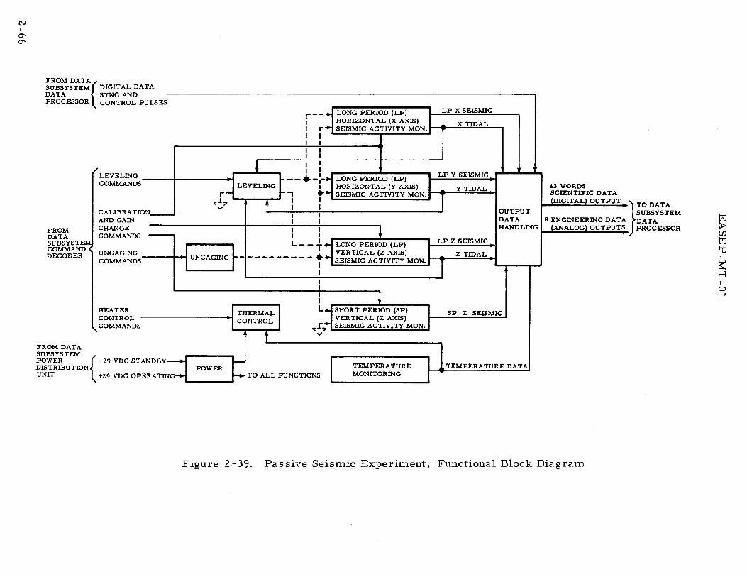
N I
0' 0'
FROM DATA{ SUB. SYSTEM DIGITAL DATA DATA SYNC AND PROCESSOR CONTROL PULSES
r LEVELING I .. 1 COMMANDS LEVELING
r-- LONG PERIOD (LP) 1 HORIZONTAL (X AXIS) I r SEISMIC ACTIVITY MON. I I I I I I I I I I I I
--•-:- LONG PERIOD (LP)
LP X SEISMIC
X TIDAL
LP Y SEISMIC
CALIBRATIONAND GAIN
1 HORIZONTAL (Y AXIS) r 1 t- , •1 SEISMIC ACTIVITY MON. ~
~~7 f f : : Y TIDAL
FROM DATA SUBSYSTEM COMMAND DECODER
CHANGE COMMANDS ---
I I I I
I I l I I
OUTPUT DATA HANDLING
UNCAGING I I L - - + ..j LONG PERIOD (LP) LP z SEISMIC
I SEISMIC ACTIVITY MON. ~ z TIDAL I COMMANDS • UNCAGING r-~------- __ +.j VERTICAL (Z AXIS)
I T 1 I
FROM DATA SUBSYSTEM
HEATER CONTROL COMMANDS
DISTRIBUTION POWER
THERMAL CONTROL
l
I I L
'l:r.,. v
POWER {+29VDCSTANDBY~ UNIT +29 VDC OPERATING TO ALL FUNCTIONS
l SHORT PERIOD (SP) VERTICAL (Z AXIS) SEISMIC ACTIVITY MON.
TEMPERATURE MONITORING
SP Z SEISMIC
TEMPERATURE DATA
43 WORDS SCIENTIFIC DATA (DIGITAL) OUTPUT
}
TO DATA SUBSYSTEM
8 ENGINEERING DATA DATA (ANALOG) OUTPUT~ PROCESSOR
Figure 2-39. Passive Seismic Experiment, Functional Block Diagram
M ~ (f).
M 1:J I
~ t-3 I
0 .......

EASEP-MT -01
2-63. PSE Monitoring Functions. The three long period seismic data channels are similar, differing only in sensor orientation in the horizontal channels, and principally in sensor type in the vertical channel. The swinging gate type sensors in the horizontal channels respond to tilting as well as lateral displacement of the lunar surface, while the LaCoste spring suspension of the vertical sensor enables it to measure changes in gravitational acceleration as well as its primary function to detect surface displacement in the vertical axis. Seismic data is obtained in the following :i:nanner: a capacitance type transducer in each LP sensor provides a phase -referenced, output signal proportional to the amplitude of displacement of the sensor frame from its seismic mass. This signal is amplified, phasedemodulated, and filtered to produce the LP seismic output signal for that axis. Very low frequency filtering of this signal produces its tidal component. The short period channel is generally similar to the long period channels, although a coil-magnet type transducer is employed to produce a single seismic output proportional to the velocity rather than the amplitude of displacement of its seismic mass. The seismic mass in each of the four channels has a separate coil-magnet assembly associated with command-controlled step voltages to produce known input accelerations to each inertial mass for calibration purposes. In the LP sensors the coil-magnet assemblies are also used for damping and stabilization of the LP seismic masses by means of negative feedback of the tidal signal. Signal amplification in each of the four data channels is command controlled. Fixed steps of attenuation may be switched in and out of the signal path as required. The two output signals from each of the three LP channels, plus the output signal from the SP channel, are provided as analog signals to the PSE data handling circuits. The signals are digitized and supplied to the PSEP data subsystem as seven of the eight PSE scientific data output signals.
The relative positions of the LP sensors varies with temperature. The temperature of the sensor assembly is monitored by a temperature sensor in its base, together with a circuit which is capable of detecting changes as small as ± 0. 02 oc. The output of this circuit is applied to the PSE data handling circuits as the eighth PSE scientific data output signal, where it is digitized prior to routing to the PSEP data subsystem. It is also applied to the sensor assembly heater control circuits.
2-64. PSE Supporting Functions. The sensor assembly heater control circuits control the heater operating mode which is selected by Earth command. Three thermal control modes are provided; automatic, thermostat bypass (manual on), and off. The automatic mode is the normal mode of operation, and connects power to the heater through a thermostatic control circuit which maintains the temperature of the sensor assembly within a preset level. The thermostat bypass (manual on) mode applies continuous power to the heater. On PSEP the PSE temperature will be controlled by the mounting plate temperature. PSE heater power will be turned off after system turn-on.
The PSE data handling circuits comprise an analog-to-digital converter which converts the eight analog scientific data signals to digital form. The digital data is then formatted by the PSE into 10-bit digital words for insertion by the PSEP
2-67

EASEP-MT -01
data processor into the 43 assigned spaces in each of the 64-word PSEP telemetry word frames. Synchronization and control pulses which control the formatting and readout of the digital data, are received from the PSEP data processor. Eleven analog status signals from the PSE logic circuits and from the uncaging mechanism are combined into eight analog signals by the PSE data handling circuits for transmission to the PSEP data processor/multiplexer. The data are inserted into housekeeping word number 33 of each of the eight PSEP telemetry word frames assigned for transmission of this data.
The PSEP must be leveled to within ± 5 a before the platform can be uncaged. Further platform leveling is accomplished through automatic and/ or command (manual) positioning of the LP gimbal platform in its horizontal axes, and the spring in the LP vertical axis by means of independent, two-speed, leveling servos in each LP axis. The tidal output signal of each axis may be used as its leveling error signal in both the automatic and command modes. Mode selection and command mode positioning commands affect all three servos; however, power to the leveling motor of each servo is controlled by separate commands. The ability to activate leveling motors separately provides for independent leveling in each axis. Both the automatic and command modes have two leveling speeds, coarse and fine in the automatic, and high and low in the command mode. The coarse and/ or high speed mode(s) are normally used only to reduce leveling errors to less than three minutes of arc, and the remainder of the leveling process is done in the fine and/or low speed mode(s).
The sensors of the SP and LP seismometers must be uncaged before they become operable. Uncaging is accomplished by a pyrotechnic piston actuator which breaks the pressure seal in the pressurized bellows type caging mechanism in response to Earth command. Breaking the pressure seal allows the caging systern gas to escape, deflating the bellows, releasing the caging pins, and unlocking the inertial masses.
The PSEP power distribution unit furnishes 29 vdc operating and standby _(survival) power to the PSE. Application of this power to the PSE is controlled by the power distribution unit (PDU) of the data subsystem, which also connects standby power to the PSE heater circuit in the event of interruption of operating power. Separate PSE power converters, located in the PSE central station electronics module, convert PSEP +29 vdc operating power into the various voltages required in the PSE circuits, as described in paragraph 2-75.
2-65. PSE Command Functions. The following functions of the PSE are controlled by commands from Earth: signal calibration and gain in the four seismic data channels; filtering in the LP feedback circuits; leveling mode, speed, direction, and axis selection during leveling of the LP sensors; and control of the sensor assembly heater operating mode. A total of 15 commands are used for these purposes. The commands are channeled over 15 separate command lines connecting the PSEP command decoder to the PSE central station electronics. The PSE CSE routes the commands over separate lines to the sensor assembly.
2-68

EASEP-MT -01
The transmission of a command froman MSFN station on the Earth to the PSE results in the generation of a command pulse by the PSEP command decoder on the appropriate command line to the PSE. Each of the 15 incoming PSEP command lines is terminated in the PSE central station electronics by a logic circuit which has two or more stable states, one of which is preset by the application of PSEP power to the PSE. Each of the two or more logic states represents a certain command, such as power on or power off to the associated circuit. Receipt of the command puls
1e from the command decoder causes the logic circuit
to advance to the next stable state, changing the control voltage it applies to the associated circuit. The preset function ensures that the signal or power circuit element associated with each command is in the desired state when power is applied. The preset state of each command is listed with the associated function in Table 2-15. (Refer to Appendix A.}
All of the 15 command logic circuits are comprised of one or more flip-flops. Four of the logic circuits consist of a two-bit, serially connected counter which provides four stable output states. Three of these counters control switches which select sections of step attenuators in the signal paths and in the calibration circuits of the four seismic data channels. The fourth counter controls switching relays in the sensor assembly heater control circuits. The eleven remaining flip-flops control switches applying power to associated circuits.
The preset logic circuit is a form of one-shot multivibrator, which generates the preset pulse to the other logic circuits when triggered by the application of operating power.
Table 2-15. PSE Command Functions
Commands
C L-9 Uncage (ARM/ FIRE}
CL-13 Feedback Filter (IN/OUT)
CL-15 Leveling Mode (AUTOMATIC/ MANUAL}
C L-11 Leveling Speed (LOW/HIGH}
Functions
The simultaneous uncaging of all four seismic sensors. Requires separate arm and fire commands.
Switches the feedback (tidal} filters in all three LP channels in or out simultaneously.
Switches leveling mode of operation from automatic to manual, or the reverse, in all three LP axes.
Switches leveling speed in all three LP axes from low to high, or the reverse, while leveling in the manual mode.
Preset State
CAGED
OUT
AUTOMATIC
LOW
2-69

EASEP-MT -01
Table 2-15. PSE Command Functions (cont)
Commands
CL-10 Leveling Direction (PLUS/MINUS)
CL-14 Coarse Level Sensor (IN/OUT)
CL-6 Leveling Power, X Motor (ON/OFF)
CL-7 Leveling Power, Y Motor (ON/OFF)
CL-8 Leveling Power, Z Motor (ON/OFF)
CL-1 Gain Change, LP X, LP Y
CL-2 Gain Change, LP Z
C L-5 Gain Change, SP Z
C L-4 Calibration, LP (ON/OFF)
CL-3 Calibration, SP (ON/OFF)
CL-12 Thermal Control Mode (AUTO/ MANUAL)
2-70
Functions
Switches leveling direction in all three LP axes plus, or minus, while leveling in the manual mode.
Switches power to coarse level sensors on or off.
Switches power on or off to leveling motor in LP X horizontal axis.
Switches power on or off to leveling motor in LP Y horizontal axis.
Switches power on or off to leveling motor in LP Z vertical axis.
Progressively cycles the attenuators in the X and in the Y axes signal channels through 0, -10, -20, and -30 db steps. Requires one command per step, or a total of four for a complete cycle. The attenuators in the X and in the Y axes calibration circuits are cycled through -30, -20, -10, and 0 db steps at the same time.
Same as CL-1, except that only two attenuators, one in the signal, and one in the calibration circuit, are involved.
Same as C L-2
Switches power on or off to the step attenuators in the calibration circuits of all three LP axes.
Switches power on or off to the step attenuator in the SP calibration circuit.
Progressively steps the heater control circuits through four steps, automatic mode ON, OFF, and thermostat bypass mode ON OFF.
Preset State
PLUS
OUT
OFF
OFF
OFF
Signal -30 db
Calibrate 0 db
Same q.s CL-1
Same as CL-1
OFF
OFF
AUTO

EASEP-MT -01
2-66. PSE DETAILED FUNCTIONAL DESCRIPTION
The seven seismic and tide nwnitoring channels and the temperature monitoring channel may be described as the monitoring function. The output data handling, uncaging and leveling, thermal control, and power functions may be described as the supporting functions. The following paragraphs provide detailed functional descriptions of the monitoring and supporting functions.
2-67. PSE Monitoring Functions. The long period (LP) seismometer monitoring channels are described first, followed by descriptions of the short period (SP) seismometer channels and the sensor assembly temperature monitoring channel.
2-68. Long Period (LP) Channels -Each LP sensor channel (Figure 2-40) contains signal processing, electromechanical feedback, and calibration circuits. The sensors in the two PSE horizontal channels (X and Y) are identical, employing swinging gate boom and mass assemblies with capacitor signal pickoff. These sensors are mounted at right angles to each other on the LP leveling platform. The boom of the X channel sensor is oriented along the Y axis of the platform, and the boom of the Y channel sensor is oriented along the X axis of the platform. Displacement of the X sensor frame with respect to its seismic mass occurs in the X axis of the platform; at right angles to its boom. The Y axis sensor functions similarly with respect to the Y axis. The gimbal platform is oriented during deployment so that its X and Y axes are horizontal and are located along known lunar azimuths. The vertical (Z) component seismometer is a LaCoste type spring suspension. The suspension spring is mounted between the horizontal X and Y axes. All three sensors must be leveled by adjustments to the platform and centering motors before they can produce useful output data. (Refer to paragraph 2-73. )
Lateral displacement of the horizontal sensors is controlled both by restoring from a centering Bendix flexure support and by feedback of the tidal signal to the damping coil of the sensor. The frequency of the electrical feedback loop is normally reduced to near de levels by insertion of a feedback filter in order to produce the tidal output signal for that axis. However, displacement resulting from surface tilting cannot be entirely compensated for by feedback. If the tilting is large enough, releveling of that axis will be required.
Each of the LP sensors contains a transducer consisting of three parallel capacitor plates. The center plate is mounted on the sensor frame, while the two outer plates are mounted on the seismic mass. The outer plates are connected to the balanced output of a 3 KHz oscillator. When the sensor is properly leveled the center plate is centered midway between the outer plates, in a null voltage plane. Displacement of the frame shifts the center plate away from the null plane, inducing a voltage in the plate in phase with that on the outer plate it is approaching. The amplitude of the induced voltage is proportional to the amplitude of displacement. The voltage induced in the center plate is applied to the signal processing circuits at that sensor. These circuits which comprise a
2-71

EASEP-MT -01
preamplifier, phase demodulator, second amplifier, step attenuator, postamplifier, and low pass filter, convert the voltage into the seismic output signal for that channel.
' r; SEISMIC SENSOR 1-
y
i I I
I FEEDBACK CALIB. COIL
CA LIBRATE L P-H (X&Y)
R LP-Z -0 (P 0
OWER ON OR FF) COMMANDS
3KHz osc
1
PRE-AMPL
L. P. CALIB LOGIC
GAIN CHANGE LP-H (X&Y) OR LP-Z (0, -10, -2.0,-30 DB)
FEEDBACK FILTER (INOR OUT) COMMANDS
r-
r-
I DEMO D. - AMPL STEP POST-
hi+ ATTEN. - AMPL ~
FEEDBACK FILTER BY-PASS -SWITCH
ISOLATION NETWORK
+2.. 5+ VDC
1 X ANDY, ORZ CALIB. CALIB. -- STEP SIGNAL ATTEN SWITCH
t LP X&Y,OR Z ATTEN LOGIC
FEED-BACK TO X, Y, & Z AXES FILTER FILTER BY-PASS SWITCHES LOGIC
LO-P ASS FILTER
FEED-
BACK
FILTER
~
~ ....
SEISMIC OUTPUT SIGNAL TO PSE OUTPUT DATA HANDLING FUNCTION
TIDAL OUTPUT SIGNAL TO PSE OUTPUT DATA HANDLING AND LEVELING FUNCTIONS
Figure 2-40. PSE Long Period Seismic Activity Monitoring Function, Block Diagram
The preamplifier provides the necessary amplification of the sensor output prior to its demodulation. The phase demodulator demodulates the preamplifier output signal with reference to the phase of the 3 KHz oscillator signal on one of the outer sensor plates. The phase demodulator also provides a de output voltage whose polarity and amplitude are proportional to the direction and amount of displacement of the sensor elements. The output of the demodulator is amplified in the second amplifier and is then applied to the following two separate units. The first of these units is the step attenuator in the seismic signal path. The step attenuator provides fixed steps of 0, -10, -20, and -30 db attenuation of the signal according to commands received from Earth. The signal passed by the attenuator is amplified in the post-amplifier for application to the low pass filter which highly attenuates signal components above 1 Hz. The output of the low pass filter is supplied to the output data handling circuits as one of the eight PSE scientific data outputs. The second separate unit is the filter bypass switch in the electromechanical feedback signal path. The filter bypass switch is operated by
2-72

EASEP-MT -01
command. The output of the second amplifier may be applied either through the low pass filter and isolation network of the feedback circuit to the feedback coil of the seismic sensor, or the filter may be bypassed and the signal applied directly to the network and coil. The filter separates the tidal component from the seismic signal for use as (a) one of the experiment scientific data outputs, (b) a long period feedback signal for stabilization and re -centering of the sensor following periods of seismic activity, and (c) a position error signal for leveling the channel sensor. The filter is bypassed when high rates of damping of the sensor movement are required, such as during coarse automatic or high speed command (mannual on) leveling of the horizontal sensors, or periods of unusually high seismic activity. The filter bypass switches in the feedback paths of all three of the LP channels are operated simultaneously by being connected to one flip-flop logic circuit terminating the feedback filter command line. The preset state of the logic circuit closes the bypass switches.
The gain control and signal calibration functions are identical in all three LP axes. The gain control function in each axis is independent of the calibration function; however, individual calibration voltages in the calibration function are selected through the gain change commands of the gain control function.
The gain control function controls the total amplifier gain in each seismic channel by switching individual sections of the step attenuator channel in and out of the seismic signal path. The attenuators in the two horizontal axes are switched together. An attenuator logic circuit consisting of a serially connected flip-flop counter terminates the X and Y axes gain change command line. This counter is stepped by individual gain change commands through four sequential states. Each state provides a combination of output voltages controlling solid-state switches in the step attenuators of the horizontal axes. The counter advances one step each time a command pulse is received, increasing the total impedance of the attenuator in 10 db steps, from 0 db through -30 db. A separate logic circuit, identical to that controlling gain in the two horizontal channels, terminates the Z axis gain change command line and controls gain in the LP vertical channel. The functioning of the gain control circuits of this channel are identical to those of the horizontal channels previously described.
Alternate outputs of the logic circuits controlling seismic signal gain in each of the three LP channels are applied to attenuator circuits in the signal calibration circuits of each channel. The signal calibration function is used together with the gain control function to generate LP output signals with amplitudes which represent known sensor displacements. The signal calibration circuits of each LP sensor are comprised of a calibration logic circuit, two calibration signal switches, two step attenuators, three isolation networks, and the feedback calibration coils. The calibration logic circuit consists of a flip-flop. In its preset state the logic opens the two solid -state calibration signal switches (X and Y, and Z). The logic state may be changed by command. When closed by the LP calibrate command, the switches apply a +2. 5 -volt reference signal from the PSE power distribution system to the step attenuator in each of two calibration circuits.
2-73

EASEP-MT -01
One calibration circuit applies the reference signal to the sensors in the two horizontal channels and the other calibration circuit applies the reference signal to the sensor in the vertical channel. The impedance of each attenuator is controlled by the gain change commands, which vary the alternate output of the gain control function logic (counter) governing seis1nic signal gain in the same channels. The alternate outputs are used to provide minimum attenuation (0 db) of the calibration signal with maximum attenuation ( -30 db) of the seismic signal conversely. The preset state of the gain control logic switches the calibration step attenuator to the -30 db step. The outputs of the attenuators are applied to the isolation networks, and then to the feedback calibration coil of the sensor involved. The isolation networks prevent feedback of the calibration signal into the seismic signal path. However, when the de voltages are applied to the feedback calibration coil, steady displacements of known amplitude are produced which in turn produce a de output signal in the associated channel representing the known amount of applied acceleration.
2-69. Short Period (SP) Channel - The SP channel (Figure 2-41) is similar to the long period channels, differing primarily in the type and frequency range of its sensor, the number of components, and the character of its output signal. The SP seismometer comprises a velocity type sensor and signal processing and calibration circuits.
CA LIBRATE . P. s
(PO OR co
WER ON OFF)
MM1NDS
SP CALIB. LOGIC
I GAIN CHANGE,
S. P. ANDS COMM
(0, - 1 -30DB
0, -20, )
STEP r .. SEISMIC r- PRE- r-SENSOR AMP ATTEN. ,-
v'
t I
L----------, +2. 'VDC
I I I
CALIB. SP -CALIB. - CALIB.
STEP SIGNAL COIL
ATTEN. SWITCH
J
SP - ATTEN. LOGIC
POST-- AMP - LO-PASS FILTER
r--
SEISMIC OUTPUT SIGNAL TO PSE OUTPUT DATA HANDLING FUNCTION
Figure 2-41. ~SE Short Period Seismic Activity Monitoring Function, Block Diagram
2-74

EASEP-MT-0 1
The SP sensor is comprised of a permanent magnet seismic mass suspended by a leaf spring and stabilizing delta rods. The mass is designed to move vertically within a coil mounted vertically in one hemispherical base of the sensor. This configuration is sensitive to rate of motion in the vertical axis, but less sensitive to lateral or tilting motions, and does not require leveling beyond that provided during deployment (±5o of vertical). A sensor coil magnet assembly similar to those of the LP sensors is used for calibration purposes.
The voltages induced in the SP sensor output coil by motion of the lunar surface in its vertical plane are applied to the SP signal processing circuits. These circuits consist of a preamplifier, step attenuator, post-amplifier, and low pass filter. The preamplifier provides amplification of the sensor output signal, prior to transmission of this signal from the sensor assembly to the remaining signal processing circuits which are located in the PSE central station electronics subassembly. Control of the total amplification of the SP seismic signal is provided by the step attenuator, as in the LP channels. The signal passed by the attenuator is amplified in the post-amplifier for application to the low pass filter. Since higher frequency components are present in the SP signal than in the LP signals, the SP low pass filter has a higher cutoff frequency. The filter output is applied to the PSE output data handling circuits as one of the PSE scientific data output signals. No tidal signal is produced by the SP sensor.
The SP gain control function is like that of the LP channel. A counter logic circuit terminates the SP gain change command line controlling a step attenuator in the SP seismic signal processing circuits.
The SP signal calibration function is similar but not identical to that of the LP vertical axis. A logic circuit, step attenuator, calibration signal switch, and one coil magnet assembly in the SP sensor are employed. The logic circuit which terminates the SP calibrate command line is a flip-flop which controls the calibration signal switch. In the SP calibration circuits, the 2. 5 -volt reference signal from the PSE power converter is applied to the step attenuator (instead of to the calibration signal switch) and the output of the attenuator is then applied to the switch. The impedance of the SP step attenuator is controlled by the alternate output of the logic (counter) terminating the SP gain change command line, as in the LP calibration circuits. When the calibration signal switch is commanded on, by its logic circuit, the attenuator output is connected to the calibration coil on the SP sensor. The calibration voltage is a step function producing a known acceleration of the SP sensor seismic mass.
Two command lines from the data subsystem are provided for control of the SP calibration function. The primary SP calibrate command is routed through the PSEP command decoder and carries Earth-originated command pulses. In
2-75

EASEP-MT -01
the event of uplink failure, a second calibrate cormnand is provided from the central station timer in the data subsystem. These backup pulses provide automatic calibration of the SP channel signal every 12 hours, using the existing attenuator settings.
2-70. Temperature Monitoring Channel - The PSE temperature monitoring channel develops an output signal porportional to the temperature of the sensor assembly. It consists of a temperature sensing bridge circuit and a differential amplifier. A 3 KHz signal, from the 3 KHz oscillator in the LP seismic channels, is applied to the input of the bridge circuit which is balanced at 125 oF. Two thermistors in the bridge arms are mounted on the base of the sensor assembly, and sense changes in its temperature. Changes as small as 0. 02 oc are enough to unbalance the bridge circuit sufficiently to develop a temperature output signal from the differential amplifier which is proportional to the direction and amount of change. This signal is applied to the PSE output data handling circuits as one of the experiment scientific data outputs.
2-71. PSE Supporting Functions. The supporting functions comprise data handling, uncaging and leveling, thermal control and power functions.
2-72. Data Handling - The output data handling function circuits (Figure 42) handle the conversion of the analog output signals of the eight scientific data channels into digital form, the formatting of the digital data into 10- bit words for serial insertion into each of the 90 PSEP telemetry frames in one cycle, and the combining of 11 analog status signals into eight analog channels for insertion into housekeeping work number 33 of each of eight PSEP telemetry frames.
The output data handling circuits consist of eight major functional blocks, which are program control and buffer amplifiers, frame position counter, data channel selector, analog multiplexer, analog-to-digital converter transfer gates, shift register, and housekeeping data addition and transfer networks.
The program control and buffer amplifier subfunction provides timing and control pulses to the other subfunctions. It is the interface between the PSE data handling circuits and the PSEP data subsystem. The buffer amplifiers terminate the input and output lines to and from the PSEP data subsystem, providing isolation of these lines from the PSE circuits.
The frame position counter provides telemetry frame and word position pulses to the data channel selector, enabling it to select the multiplexer data channel assigned to each of the 43 PSE data words in each PSEP telemetry frame at the appropriate times.
The data channel selector decodes the frame position counter outputs and uses them to control the gating of each of the eight PSE scientific data outputs through the analog multiplexer to the analog-to-digital converter in the PSE central station electronics module. The data channel selector causes the multiplexer to sample
2-76

N I -.] -.]
PSE SCIENTIFI
DATA ~
LP X SEISMI LP Y SEISMI LP Z SEISMI LP X TIDAL LP Y TIDAL LP Z TIDAL SP SEISMIC S.A. TEMP.
LEVELIN DIRECT!' LEVELIN SPEED LEVELIN MODE COARSE SE~$0R X & Y GA
G >N G
G
N
..
..
..
...
...
...
...
...
LP CALIB
SP CALI
Z GAIN
SP GAIN
THERMA CONTRO
RATE-
RATE-
L [...
UN CAGE D
DATA CHANNEL ...,.._ SELECTOR
T
ANALOG MULTI- ~ PLEXER
HOUSE-KEEPING DATA ADDITION
AND TRANSFER NETWORKS
FRAME POSITION COUNTER
I A/D 10 TRANSFER
CONVERTER LINES
I
LEVELING SPEED AND DIRECTION
LEVELING MODE
GATES
AND COARSE SENSOR MODE
LP AMPL GAIN, X & Y
CALIBRATION STATUS LP & SP
LP AMPL GAIN, Z
SP AMPL GAIN, Z
THERMAL CONTROL MODE
UNCAGE STATUS
l 10 SHIFT
LINES REGISTER ~
ANALOG OUTPUTS TO DATA SUBSYSTEM
PROGRAM CONTROL
AND BUFFER AMPLIFIERS
f
Figure 2-42. PSE Data Handling Function, Block Diagram
EVEN FRAME MARK PULSES DATA GATE PULSES
DEMAND PULSES
SHIFT PULSES
43 WORDS PSE DIGITAL
(SCIENTIFIC) OUTPUT DATA
~ Cll txj
1-Q I
~ 1-3 I 0 1-'

EASEP-MT -01
the short period seismic signal a total of 29 word-times in each PSEP telemetry frame. The three long period seismic signals are each sampled four word-times in each PSEP frame. The tidal signals in each of the two LP horizontal axes are sampled once every even frame. The tidal signal in the LP vertical channel and the sensor assembly temperature signal are sampled every odd frame.
The analog multiplexer gates each of the eight scientific data output signals to the analog-to-digital converter in the PSE central station electronics module according to the control pulses received from the data channel selector.
The transfer gates are enabled by program control pulses to shift the 10-bit data words out in parallel from the digital-to-analog converter and into the shift register at the appropriate times.
The PSE digital scientific data comprises 43 of the 64 words in each PSEP telemetry frame. Each data word consists of 10 NRZ bits. A listing of PSE telemetry word assignments is given in Table 2-16 and in the Appendix. PSE data word locations in the PSEP telemetry frame are shown in Figure 2-43. 1 The normal PSEP bit repetition rate is 1060 bps. Under difficult telemetry communications conditions, the slow PSEP bit rate, which is half the normal rate, may be used.
The housekeeping data addition and transfer networks combine 11 status signals into eight channels and transfer these analog data to the PSEP data processor analog multiplexer. Three pairs of command status signals are added in resistor networks to form three combination signals. These three signals and the five single signals are applied to the data processor. The three summed pairs of signals are the outputs of the logic circuits terminating certain command lines and in each case are a change in level expected as the result of the transmission of associated commands. The eight analog signals are listed in Table 2-16 along with the telemetry frame in which they are transmitted in housekeeping word number 33.
Both synchronization and data control pulses are received from the PSEP data processor for controlling the PSE output data handling functions. Even frame mark, data gate, and shift pulses are provided by the PSEP data processor to synchronoize and control the formatting of the PSE data into 10- bit words compatible with PSEP telemetry requirements. The even frame mark pulses mark the beginning of each even numbered telemetry frame and are used in the program control, frame position counter, and data channel selector subfunctions. The demand pulses are one 10- bit word in length and are generated by the data processor for use in the program control circuits to gate data out of the shift register, on demand, to the data processor.
2-73. Uncaging and Leveling- Uncaging and leveling are separate, but related functions which are grouped together in this description for the purpose of discussion. (See Figure 2-44. ) Uncaging must be performed after deployment before
2-78
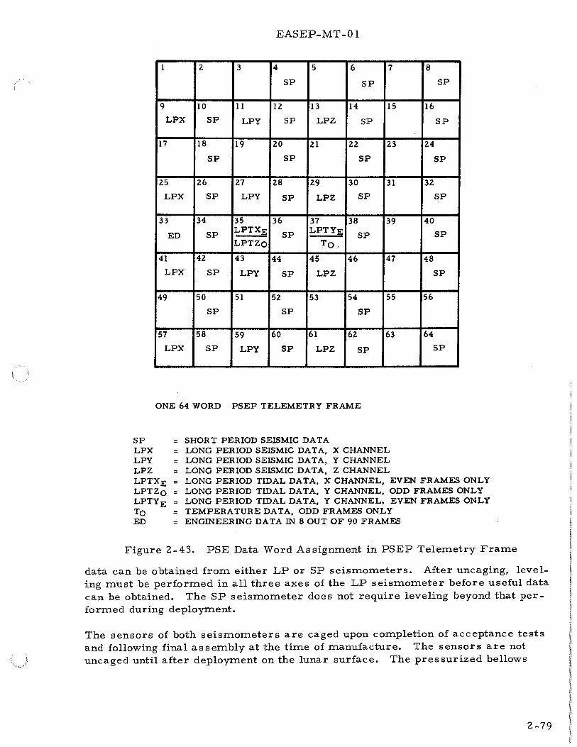
EASEP-MT-0 1
1 z 3 4 5 6 7 8
SP SP SP
9 10 11 12 13 14 15 16
LPX SP LPY SP LPZ SP SP
17 18 19 20 21 zz 23 24
SP SP SP SP
25 26 27 28 29 30 31 32
LPX SP LPY SP LPZ SP SP
33 34 35 36 37 38 39 40
ED SP LPTXE SP LPTYE
SP SP LPTZo To,
41 42 43 44 45 46 47 48
LPX SP LPY SP LPZ SP
49 50 51 52 53 54 55 56
SP SP SP
57 58 59 60 61 62 63 64
LPX SP LPY SP LPZ SP SP
ONE 64 WORD PSEP TELEMETRY FRAME
SF LPX LPY LPZ LPTXE LPTZo LPTYE To ED
= = = = = = = = =
SHORT PERIOD SEISMIC DATA LONG PERIOD SEISMIC DATA, X CHANNEL LONG PERIOD SEISMIC DATA, Y CHANNEL LONG PERIOD SEISMIC DATA, Z CHANNEL LONG PERIOD TIDAL DATA, X CHANNEL, EVEN FRAMES ONLY LONG PERIOD TIDAL DATA, Y CHANNEL, ODD FRAMES ONLY LONG PERIOD TIDAL DATA, Y CHANNEL, EVEN FRAMES ONLY TEMPERATURE DATA, ODD FRAMES ONLY ENGINEERING DATA IN 8 OUT OF 90 FRAMES
Figure 2-43. PSE Data Word Assignment in PSEP Telemetry Frame
data can be obtained from either LP or SP seismometers. After uncaging, leveling must be performed in all three axes of the LP seismometer before useful data can be obtained. The SP seismometer does not require leveling beyond that performed during deployment.
The sensors of both seismometers are caged upon completion of acceptance tests and following final assembly at the time of manufacture. The sensors are not uncaged until after deployment on the lunar surface. The pressurized bellows
2-79
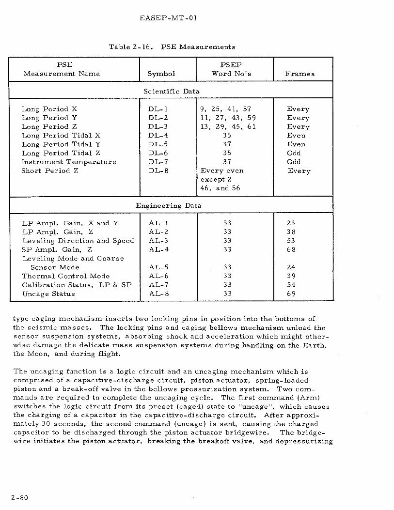
EASEP-MT -01
Table 2-16. PSE Measurements
PSE PSEP Measurement Name Symbol Word No's Frames
Scientific Data
Long Period X DL-1 9, 25, 41, 57 Every Long Period y DL-2 11, 27, 43, 59 Every Long Period z DL-3 13, 29, 45, 61 Every Long Period Tidal X DL-4 35 Even Long Period Tidal Y DL-5 37 Even Long Period Tidal Z DL-6 35 Odd Instrument Temperature DL-7 37 Odd Short Period Z DL-8 Every even Every
except 2 46, and 56
Engineering Data
LP Ampl. Gain, X andY AL-l 33 23 LP Ampl. Gain, z AL-2 33 38 Leveling Direction and Speed AL-3 33 53 SP Ampl. Gain, z AL-4 33 68 Leveling Mode and Coarse
Sensor Mode AL-5 33 24 Thermal Control Mode AL-6 33 39 Calibration Status, LP & SP AL-7 33 54 Uncage Status AL-8 33 69
type caging mechanism inserts two locking pins in position into the bottoms of the seismic masses. The locking pins and caging bellows mechanism unload the sensor suspension systems, absorbing shock and acceleration which might otherwise damage the delicate mass suspension systems during handling on the Earth, the Moon, and during flight.
The uncaging function is a logic circuit and an uncaging mechanism which is comprised of a capacitive-discharge circuit, piston actuator, spring-loaded piston and a break-off valve in the bellows pressurization system. Two commands are required to complete the uncaging cycle. The first command (Arm) switches the logic circuit from its preset (caged) state to ''uncage'', which causes the charging of a capacitor in the capacitive-discharge circuit. After approximately 30 seconds, the second command (uncage) is sent, causing the charged capacitor to be discharged through the piston actuator bridgewire. The bridgewire initiates the piston actuator, breaking the breakoff valve, and depressurizing
2-80

UN CAGING (ARM AND UNCAGING UNCAGE) LOGIC COMMANDS -.
PRESET.,
FEEDBACK FILTER (IN-- FEEDBACK OR OUT) ~ FILTER COMMANDS LOGIC
PRESET- I LEVELING :~
Z AXIS LEVELING LOGIC
POWER, Z MOTOR (ONOR OFF) COMMANDS
PRESET-...J COARSE SENSOR COARSE (POWER ON-+ LEVELING OROFF) LOG~
COMMANDS PRESET.)
LEVELING LEVELING MODE ___. MODE COMMANDS LOGIC
PRESET.:; + COMMAND
+12 VDC__. LEVELING
LEVELING
MODE SWITCH
COMMAND DIRECTION LOGIC
+12 rDc
Z AXIS LEVELING SWITCH
COARSE t--------------..a LEVELING
AUTOMATIC 1---.....ot-t LEVELING
MODE SWITCH
SWITCH
EASEP-MT-01
t
,--..!;Z;:.....,;T~ID~A~L;.:S~I~G~N:..::Al:!L:;,_ _____ -l.-1 Z AXIS ( LP) ~---, SENSOR l ..,. SEISMIC ACTIVITY L.....--1 ... - UNCAGING ----- J ,..... MONITORING l"""'"r¢{-11 MECHANISM
Z AXIS LEVELING I Z AXIS LEVELING CONTROL CIRCUITSI J I MOTOR
I I I
_j I I ~~·~--------~ -----r---- XAXIS .. ----t--e-• YAXIS SEISMIC ACTIVITY ~- I SEISMIC ACTIVITY -MONITORING _.-, I r • MONITORING
I I I '-----.....;;;;;.....;;;..,_ _ _, X TIDAL SIGNAL I I I
I I 1
COARSE X AXIS COARSE X AND Y AXIS r-- - ~---, LEVELING .... --+~ LEVEL SENSOR !+-- !!EVE LING ._ • y AXIS COARSE ~ I DRIVE PLATFORM LEVEL SENSOR
I ~~VEELING L- ...... - -----..: ,,__ '-o-+'1 ___ ; .... ~ ___ ____.l I SWITCH - BI-DIR. LEVELING ! ! DRIVE PULSE ~ MOTOR ~r~--...
.--+---t-fi--f COMMAND ~ GENERA TOR DRIVE I X AXIS I y AXIS .... -4-+----...... .t,.I--..J LEVELING J ILEVELINGI I LEVELING
._-+-.,__-1-__ i.___. DRIVE MOTOR "':::J ~? MOTOR T X AXIS LEVELING I
(-)COMMAND DIRECTION 1--------J SWITCH
(+)COMMAND DIRECTION t-----------+-~
1---___,..t SWITCH
I LEVELING +29 vDc- MOTOR CONTROL POWER SWITCH I
L---~~:_ _______ _j (-) DIRECTION _., COMMANDS .._ _____ _.
PRESET~ Y TIDAL SIGNAL
LEVELING SPEED ~ COMMAND COMMANDS SPEED LOGIC
LEVELING POWER, X MOTOR (ON OR OFF) COMMANDS
LEVELING POWER, Y MOTOR (ON OR OFF) COMMANDS
PRESET..J
_., X AXIS LEVELING LOGIC
PRESET.J.
Y AXIS LEVELING LOGIC
PRESET
COMMAND SPEED SWITCH
X AXIS LEVELING SWITCH
+12 rDC Y AXIS LEVELING SWITCH
COARSE LEVELING~-------------------------------------~~~ DRIVE
r------1...---_j-..., ~~ jl
Y AXIS LEVELING CONTROL CIRCUITS ~~----------------------------_J
____ j J
1 ......
Figure 2-44. PSE Uncaging and Leveling Function, Block Diagram
2-81/2-82

EASEP-MT-01
the caging bellows. The bellows are collapsed by springs, withdrawing the locking pins from the inertial masses and loading the suspension system.
Position type servo mechanisms are employed to independently level each LP axis. The horizontal axes have identical leveling drives and the vertical axis is similarly centered by means of a motor drive. (See Figure 2-44.)
The X and Y axes leveling motors physically position the gimbal platform as well as their respective sensors, while the Z motor positions its sensor with respect to the platform. Changes in platform position in the horizontal axes thus affect the position of the vertical axis sensor, requiring that it be centered last.
The servo mechanisms used in each LP axis have two modes of operation; automatic and command. The automatic mode uses position-error signals generated within the PSE sensor, while the command mode uses positioning signals generated by Earth-command. Two speeds of operation are provided in each mode; coarse and fine in the automatic mode, and high and low in the command mode. The automatic-coarse mode is used with position error signals from the corresponding (X or Y) coarse level sensors on the leveling platform to achieve leveling in the X and Y axes. These position-error signals are used to reduce the relatively large initial off-level (± 5 degrees) which is possible from the manual leveling process during deployment. Following the coarse leveling sequence, the automatic-fine leveling mode is used. In this mode, the tidal output signal of the seismic channel is employed as the position-error signal. This process is designed to reduce leveling errors of the LP seismometers to less than three seconds of arc. The command mode leveling speeds may be similarly used for leveling by Earth positioning commands, using the telemetered tidal and seismic signal data from the channel being leveled as the position-error signal. A total of up to two hours may be required for completion of the fine leveling in all three axes after deployment and verification of system operation. Selection of the axis to be leveled, and leveling mode, speed, and direction are controlled by seven Earth commands. The vertical axis leveling modes are similar to those of the horizontal axes. However, the automatic-coarse speed leveling mode is not used for the vertical component.
Figure 2-44 shows the leveling function circuits of all three axes as well as their interrelationships. These circuits consist of command logic and switching circuits, leveling control circuits, their associated leveling motors, and positionerror signal generation circuits.
The command logic and switching circuits terminating each of the command lines associated with leveling are shown in Figure '2-44. These circuits comprise logic circuits controlling the feedback filter bypass switches of each axis, power to the leveling motors of each axes, leveling mode, and command leveling speed and direction. The feedback filter logic circuit is used to switch the feedback filter out of the feedback loop (simultaneously in all three axes) during the automatic-coarse and command-high speed levelin~ modes. This is done to
2-83

EASEP-MT-01
decrease the sensitivity of the seismometers during leveling. The leveling logic and switching circuits control application of operating power to the leveling motor drive circuits of their respective axes. The leveling mode, command leveling speed and direction logic, and switching circuits control these functions in all three axes.
Details of the leveling control circuits of the X axis are shown in a block in the center of Figure 2-44. The leveling control circuits of the Y and Z axes are indicated by a similar block. These circuits are identical for X andY, and are similar for Z. The circuits comprise a leveling motor power switch, fine (automatic) and command leveling drive circuits, bi-directional pulse generator, and leveling motor drive circuits. The X andY axes include coarse leveling drive circuits for leveling of the gimbal platform (these circuits are not required for the Z axis). The three (fine, command, and coarse) leveling drive circuits are each enabled in their associated leveling mode. The level drive circuits convert leveling positionerror or direction and speed input signals into polarized outputs for operation of the bi-directional drive pulse generator. The bi-directional drive pulse generator generates a series of output pulses with width and polarity proportional to the amplitude and polarity of its input signals. The pulse generator output signals drive the leveling motor drive circuits by means of driving signals to the leveling motors which are proportional to the bi-directional pulse generator output. The level motor drive circuits are operated by + 29 volt power which is controlled by Earth command.
Figure 2-44 shows the relationship of the leveling platform and motors, the three LP seismic activity monitoring functions (which generate the position error signals for leveling in the automatic-fine mode), and the coarse sensors of the X andY axes (which generate the position error signals for the automatic-coarse mode of
leveling these axes. )
The functions of the leveling servo loops in the different modes of operation are described by following the leveling commands and error signals through the leveling servo circuits of the X axis. The circuits of the other axes function in a simi
lar manner.
Leveling of the X axis requires that power be applied to the X axis leveling motor by command. A pulse must be applied to the logic circuit terminating the leveling power X motor command line because the preset state of this logic circuit results in the operating power circuit of the X axis leveling motor being open. The cornrnand pulse switches the logic circuit to its alternate state, closing the associated X axis leveling switch, and connecting a de voltage to the leveling motor power switch in the X axis leveling control circuits. The leveling motor power switch is closed by the de voltage and applies +29-volt operating power to the leveling motor drive circuits.
The leveling mode logic circuit selects either the automatic qr command leveling mode according to its output state. The preset state of the leveling mode logic circuit closes the automatic leveling mode switch applying a de voltage to the
2-84

EASEP-MT-0 1
coarse leveling switch and to the fine leveling drive circuits. With the coarse leveling logic circuit in its preset state, the coarse leveling switch is open, and power is not applied to the coarse level sensors of the horizontal axes. This permits leveling in the automatic fine leveling submode. If relatively large leveling position-errors are present after deployment, the automatic coarse leveling submode can be selected by the coarse sensor command. This command pulse sets the coarse leveling logic to its alternate state, closing the coarse leveling switch and applying power to the X and Y coarse level sensors. These sensors are mercury switches mounted on the gimbal platform. The mercury switches generate relatively large leveling position-error signals of constant amplitude with a polarity dependent on that of the position error. The output of the X axis coarse level sensor is applied to the coarse leveling drive circuits in the leveling control circuits for the X axis. The output signal of the coarse leveling drive circuit controls the output of the bi-directional pulse generator. The generator produces a series of polarized pulses with width and polarity proportional to the amplitude and direction of the leveling position error. These pulses are applied to the leveling motor drive circuit along with +29-volt operating power from the leveling motor power switch as previously described. The leveling motor drive circuits apply operating power to the leveling motor in proportion to the pulse width and polarity of the drive signal from the bi-directional pulse generator. The leveling motor slowly repositions the leveling platform about its X axis reducing the leveling position error. During the final portion of the leveling process, particularly in the fine and low speed modes, position errors are reduced to less than three seconds of arc and the leveling rates are proportionately lower and thereby slower.
A second command (pulse) applied to the coarse sensor command line resets the coarse leveling logic to its original (preset) state, restoring the automatic fine leveling submode. The tidal output signal of the X axis seismic activity monitoring function is also applied to the fine leveling drive circuits. The fine leveling drive circuits generate an output signal proportional to the direction and amplitude of the leveling position error. This signal is applied to the bi-directional drive pulse generator, controlling its output in the same manner as the output signals of the coarse leveling drive circuits.
The command leveling mode is selected by the alternate state of the leveling mode logic circuits. The preset state of the logic circuit is changed to the alternate state by a command pulse on the leveling mode command line. The alternate state opens the automatic leveling mode switch and closes the command leveling mode switch. Opening the automatic leveling mode switch disables both the fine leveling drive circuit and the coarse leveling switch, effectively disabling both of the automatic leveling submodes. Closing the command leveling switch connects power to the plus and minus (leveling) direction switches. The preset state of the command (leveling) direction logic closes the plus direction switch and opens the minus direction switch. The output voltage of the plus direction switch is applied to the command leveling drive circuit in the X axis leveling control circuits enabling it and controlling the polarity of its output signal. A command pulse on the
2-85

EASEP-MT-01
leveling direction command line causes the command direction logic circuit to change its alternate state, closing the minus direction switch and opening the plus direction switch. This reverses the polarity of the output signal of the command leveling drive circuit. The preset state of the command speed logic circuit opens the command speed switch and opens a ground circuit to the command leveling drive circuit. The output signal of the drive circuit is then the lower of the two preset amplitude levels. A command pulse on the leveling speed command line causes the command speed logic circuit to change to its alternate state, closing the command speed switch. Completion of this circuit causes the output of the command leveling drive circuit to be the higher of its two preset states. The output of the command leveling drive circuit is applied to the bi-directional drive pulse generator, which produces output pulses proportional to the amplitude and polarity of the drive circuit signal. The output of the pulse generator controls the leveling motor through its drive circuit as in the automatic mode.
The control and leveling functions of the Y axis are identical to those described for the X axis. Those in the Z axis are similar with the exception of the coarse leveling mode circuitry. These circuits are not required in the Z axis because their function is accomplished by those of the X and Y axes and the leveling of the leveling platform.
2-74. Thermal Control - The thermal control function circuits (Figure 2-45) control the application of operating power to the sensor assembly heaters which are located in the base of the assembly. Three modes of operation are provided; automatic, thermostat bypass (manual on), and power off. The thermal control circuits comprise a logic circuit, heater power relay, bypass relay, multivibrator, heater power switch, and the heater.
Operating power is applied to the heater power relay from the PSE power distribution circuits. This relay and the bypass relay control the operating mode of the heater, and are in turn controlled by the logic circuit. The logic circuit terminates the thermal control mode command line and consists of a two- bit, serially connected flip-flop counter. The counter has a total of four two- bit output voltage combinations. One of the bit-outputs controls the heater power relay and the other the bypass relay.
In both the automatic and thermostat bypass modes the heater power relay is closed connecting operating power to the heater power switch. In the power off mode this relay is open, interrupting the power circuit. The heater power switch is turned on and off at a 3 KHz rate by the multivibrator. When the heater power switch is on and the heater power relay closed, operating power is connected to the heater.
The proportion of time when power to the heater power switch is on, is varied by the multivibrator according to the temperature signal received from the temperature monitoring circuits. A decrease in temperature lengthens the power on
2-86

TEMPERATURE SENSING BRIDGE
EASEP-MT-01
DIFFERENTIAL TEMPERATURE TO OUTPUT AMPLIFIER 1-----.... --,..DATA
SIGNAL HANDLING
3KHz--------------------------~~ MULTIVIBRATOR
29 VDC OPERATING HEATER (AND SURVIVAL)------... ... POWER POWER RELAY
HEATER POWER SWITCH
SENSOR 1-.... -" ASSEMBLY HEATER
THERMAL CONTROL THERMAL I---MODE COMMANDS-+ CONTROL
L..,.. BY -PASS I-RELAY
LOGIC 1-----------------~
+Z9 V STANDBY POWER
+Z9 V OPERA TIN POWER
Figure 2-45.
....... VVY
' IVOLTAGE I REGULATOR I
PSE Termal Control Function, Block Diagram
.... ..... 2~
+ lZ VDC RECTIFIER &: FILTER
+5 VDC INVERTER RECTIFIER
&: FILTER
-lZ VDC RECTIFIER &: FILTER
YPRESETl LOGIC I
J CONTROL l SWITCH :I:Z. 5
f VOLTAGE REFERENCE
I CURRENT SUPPLY I LIMITER
j_
Figure 2-46. PSE Power Converter Function, Block Diagram
HEATER POWER
OPERATING POWER
+lZ VDC
+5 VDC
-lZ VDC
PRESET PULSE
+Z. 5 VDC
-Z. 5 VDC
2-87
EASEP-MT-01
period and conversely. The multivibrator is driven at the 3 KHz rate by the 3 KHz oscillator in the LP seismic channels.
In the automatic mode the bypass relay is open, permitting the heater power switch to control application of power to the heater. In the thermostat bypass mode the bypass relay is closed, connecting power around the switch to the heater.
2-7 5. Power Converter - The power converter {Figure 2-46) converts PSEP +29-volt operating power to the +12, +5, -12, +2. 5, and -2. 5 de voltage required in the PSE circuits, generates the command logic preset pulse, and provides isolation of the operating and standby power lines to the sensor assembly heater.
The power converter circuits comprise an inverter, three rectifier-filter circuits, voltage regulator and control switch, current limiter, ± 2. 5 vdc reference voltage supply, preset logic and standby power isolation network.
The inverter chops the +29.:.volt operating power into a series of pulses and applies these pulses as an input signal to the three rectifier-filter circuits. The rectifierfilter circuits each consist of a full wave bridge rectifier and low pass filter, and produce the +12, +5, and -12 volt outputs. The voltage regulator and control switch control the amplitude of these de voltages by monitoring the +12-volt output. The regulator circuit contains a voltage comparator and multivibrator. The voltage comparator controls the multivibrator. The multivibrator drives the control switch to adjust the length of time power is applied to the inverter during each half of its output cycle. An increase in the amplitude of the + 12-volt supply causes a decrease in the ratio of power on to power off time, and conversely. The current limiter functions as a series regulator, limiting the maximum amount of current drawn by the inverter.
The± 2. 5-volt reference supply converts part of the output of the +12-volt supply to low ripple, low noise, +2. 5 and -2. 5 volt reference outputs for use in the PSE calibration circuits and in the PSEP data processor. It consists of a reference voltage source supplying the +2. 5 and -2.5 volt outputs and electronic series voltage regulators in each output.
The preset logic circuit is a form of one- shot multivibrator triggered by the output of the +5 volt supply. It produces the command type preset pulse to the command logic circuits when operating power is first applied to the PSE.
The standby power isolation network connects operating power to other PSE circuits as well as the heater circuits, but connects standby power only to the heater circuits.
2-88

EASEP-MT-01
SECTION ITI
LASER RANGING RETRO-REFLECTOR EXPERIMENT
3-1. INTRODUCTION
The laser ranging retro-reflector experiment ( LRRR) will reflect laser radiation incident upon it on a path nearly parallel to the incident beam. It will serve as a fiducial point on the surface of the moon to permit precise measurement by laser ranging of the distance from one or more sites on earth.
The LRRR(Figure 3-1) is a passive device requiring no electrical power source or telemetry capability.
Data obtained from this experiment will be utilized to expand knowledge in the following scientific areas:
a. The Moon's size and orbit can be more accurately determined by making a comparison of measured range data over long time periods (up to 10 years).
b. Geophysical information will be obtained by comparing range data from several Earth-based laser sites. Variations in the geocentric latitudes of the laser sites as well as their locations will be more accurately determined.
c. Measurements of the longitude of the Moon relative to Earth using the Earth's rotation and a single laser site or, better yet, two laser sites spaced 90 gee-longitudinal degrees apart, could help determine the possibility of a slow, secular decrease in the gravitational constant.
This section de scribes the LRRR in terms of its physical characteristics and functional operation. LRRR Leading Particulars are provided in Table 3-1.
3-2. LRRR PHYSICAL DESCRIPTION
The LRRR consists of a pallet and array assembly, boom attachment assembly, and rear support. The pallet and array assembly consists of the pallet assembly and the retro-reflector array assembly.
3-3. PALLET ASSEMBLY
The pallet assembly provides the structural base required for the LRRR to withstand the environments encountered in storage, transportation and handling, space flight, and lunar deployment. During operation on the Moon, the pallet assembly will provide continuing structural support as well as thermal isolation for the retro-reflector array for a survival period of up to 10 years.
3-1
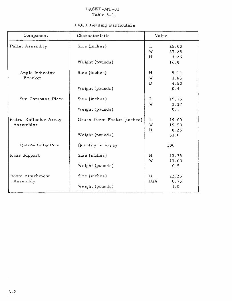
Component
Pallet Assembly
Angle Indicator Bracket
Sun Compass Plate
Retro-Reflector Array Assembly:
Retro-Reflectors
Rear Support
Boom Attachment Assembly
3-2
i ' !
.E..ASEP-MT -01
Table 3-1.
LRRR Leading Particulars
Characteristic
Size (inches)
Weight (pounds)
Size (inches)
Weight (pounds)
Size (inches)
Weight (pounds)
Gross Form Factor (inches)
Weight (pounds)
Quantity in Array
Size (inches)
Weight (pounds)
Size (inches)
Weight (pounds)
Value
L 26.00 w 27.25 H 3.25
16. 9
H 9. 12 w 1. 86 D 4.50
0.4
L 15.75 w 3.37
0. 1
L 19.00 w 19.50 H 8.25
33.0
100
H 13. 75 w 17.00
0.5
H 22.25 DIA 0.75
1.0

EASEP-MT-01
Figure 3-1. Laser Ranging Retro-Reflector Experiment
The pallet assembly provides tie points for securing the LRRR package in compartment #2 of the SEQ bay of the LM. Top surface tie points are provided for mounting the retro-reflector array, alignment handle, rear support, boom attachment assembly, angle indicator bracket, sun compass plate, and associated components. (See Figure 3-2.)
Thermal decoupling of the retro-reflector array from the lunar surface is provided by the pallet. White, thermal coating on the pallet provides a low temperature-gradient between the retro-reflector array and the pallet.
3-4. Angle Indicator Bracket. The angle indicator bracket has four index holes that relate to corresponding lunar sites. A pin on the aiming handle assembly is engaged with the appropriate hole during deployment. Index marks on the sector of the bracket identify site numbers.
3-5. Sun Compass Plate. The sun compass plate has three sets of index marks that are used to indicate correct lateral positioning of the LRRR by the shadow cast by the gnomen of the angle indicator bracket. Corresponding site numbers are adjacent to each set of index marks.
Three sun compass plates are provided to compensate for sun latitude variations that occur during a lunar year. Prior to launch, the appropriate sun compass plate for the calendar date is installed on the stowed LRRR.
3-3

Jt>
BOOM ATIACHMENT ASSEMBLY
EASEP-MT-01
Figure 3-2. LRRR Pallet Assembly
3-6. RETRO-REFLECTOR ARRAY ASSEMBLY
REAR SUPPORT
The retro-reflector array assembly consists of an array panel structure incorporating 100 retro-reflectors and an aiming handle assembly as shown in Figure 3-3.
The array is designed to survive long term (up to 10 years) passive operation in the lunar environment. Thermal protection is provided by: a thermal insulation assembly covering the sides and bottom of the array panel structure; a highlyreflective, machined top surface of the panel structure; the reflective properties of the retro-reflector cavities.
A transparant polyester pre-deployment protective cover protects the array from dust debris and contaminants during storage, transportation, handling, and flight. The protective cover is removed by the astronaut during lunar deployment.
3-7. Panel Structure Assembly. The panel structure assembly is machined from a solid aluminum block to exacting dimensions that provide the required weight and thermal characteristics. One hundred cylindrical cavities are precisely aligned to retain the retro-reflectors.
3-4
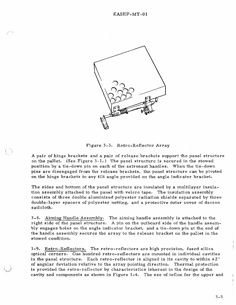
EASEP-MT-01
Figure 3-3. Retro-Reflector Array
A pair of hinge brackets and a pair of release brackets support the panel structure on the pallet. (See Figure 3-1.) The panel structure is secured in the stowed position by a tie-down pin on each of the astronaut handles. When the tie-down pins are disengaged from the release brackets, the panel structure can be pivoted on the hinge brackets to any tilt angle provided on the angle indicator bracket.
The sides and bottom of the panel structure are insulated by a multilayer insulation assembly attached to the panel with velcro tape. The insulation assembly consists of three double aluminized polyester radiation shields separated by three double-layer spacers of polyester netting, and a protective duter cover of dacron sailcloth.
3-8. Aiming Handle Assembly. The aiming handle assembly is attached to the right side of the panel structure. A pin on the outboard side of the handle as sembly engages holes on the angle indicator bracket, and a tie-down pin at the end of the handle assembly secures the array to the release bracket on the pallet in the stowed condition.
3-9. Retro-Reflectors. The retro-reflectors are high precision, fused silica optical corners. One hundred retro-reflectors are mounted in individual cavities in the panel structure. Each retro-reflector is aligned in its cavity to within ± 2 a
of angular deviation relative to the array pointing direction. Thermal protection is provided the retro-reflector by characteristics inherent in the design of the cavity and components as shown in Figure 3-4. The use of teflon for the upper and
3-5

EASEP-MT-01
RETAINER RING
CAVITY
Figure 3-4. Retro-Reflector Mounting
lower mounting rings, and the aluminum retaining ring, adjusted to a predetermined pressure, allows for variations in temperature over a range of 40 oK to 400 oK and provides thermal isolation of the individual retro-reflectors.
3-10. BOOM ATTACHMENT AND REAR SUPPORT
The boom attachment assembly is a round, tubular, post with attachment assemblies at either end for mounting to the pallet assembly and interfacing with the LM boom. An arm-like release assembly and lanyard provide boom release for manual removal of the LRRR from LM for deployment. The boom attachment assembly is detached from the pallet during handling operations at KSC, and prior to lunar deployment.
The rear support is a square, tubular, structure that mounts in guide brackets on the pallet assembly with quick-release pins. It is detached from the pallet assembly only during handling operations at KSC.
3-11. LRRR FUNCTIONAL DESCRIPTION
The objective of the LRRR is to reflect laser radiation beamed from one or more Earth-based stations. Maximum return radiation will be reflected when the retroreflector array is oriented as nearly normal to the incident radiation as possible.
3-6

EASEP-MT-01
The pallet assembly provides the functional capabilities of azimuthal orientation and leveling of the LRRR.
3-12. VERTICAL TILT ORIENTATION
The tilt angle of the retro-reflector array is set by the aiming handle assembly (Figure 3-1.) Before the array can be tilted, the two tie-down pins which secure it to the release brackets must be retracted by operating the astronaut handles. When the tie-down pins have been retracted, the array can be pivoted on its hinge brackets, by the aiming handle, to any tilt angle established by index holes in the angle indicator bracket. The site-numbered index marks on the sector of the angle indicator bracket interface with the pointer on the aiming handle to indicate the selected tilt angle.
3-13. AZIMUTH ORIENTATION AND LEVELING
The LRRR is oriented in azimuth and leveled on the lunar surface by using the alignment handle in the fully extended position (Figure 4-9. ) A trigger release on the outboard side of the handle allows the handle to be fully extended by the astronaut. The astronaut then positions the LRRR on the lunar surface, using the alignment handle, so the shadow cast by the gnomon aligns with an appropriate index mark on the sun compass plate. At the same time, he observes the bubble level, mounted on the pallet, to ensure proper leveling of the LRRR. Three sun compass plates are provided; each with markings that correspond to specific lunar sites and provide compensation for sun latitude during the time periods for the lunar landing. The appropriate plate is installed prior to launch.
3-14. BOOM ATTACHMENT AND REAR SUPPORT
The LRRR will be lowered from compartment #2 of the LM SEQ assembly to the lunar surface by means of the boom attachment assembly. The boom attachment assembly will then be removed from the pallet and discarded.
The rear support allows the LRRR to stand on end, for a time, during the course of deployment. With the LRRR up-ended, the astronaut has access to the handles so that he can tilt the retro-reflector array to the selected tilt angle, then set the LRRR upright for alignment and leveling.
3-7/3-8


EASEP-MT- 01
SECTION IV
EASEP OPERATIONS
4-1. INTRODUCTION
This section describes the operations required to enable the EASEP Flight System to accomplish its objectives of lunar scientific exploration. Operations subsequent to NASA acceptance of the EASEP flight hardware by DD-250 sign-off at Bendix will be described. This includes packaging and transportation, KSC operations, lunar surface operations, and post-flight operations.
Preservation, packaging and transportation requirements and operations will be provided in the EASEP Flight System Transportation and Handling Manual, EASEP-LS-02.
4-2. KSC OPERATIONS
KSC operations include those activities from receiving inspection of EASEP flight system packages through installation in the LM. These activities include receiving inspection, disassembly, transportation, handling, assembly, and installation as shown in Figure 4-1.
Receiving inspection of the EASEP packages and isotope heaters will be performed at the ALSEP Launch Preparation Site (ALPS) which is located in Hypergolic Test No. 2 Building, M7 -1210.
The packages will be dis as sembled to the installation assembly level, and the assemblies will be assembled on the handling ground support equipment (GSE).
The EASEP assemblies in the GSE will be transported from the ALPS to the launch umbilical tower (LUT) on the launch pad. It will be elevated to the instrument unit (IU) level, and handed through the IU door into the spacecraft/LM Adapter (SLA) section of the launch vehicle. The assemblies are then hoisted to the XA 525 level where they are removed from the GSE. The EASEP packages are assembled on the GAEC installation fixture, and installed in the LM SEQ bay.
4-3. GROUND SUPPORT EQUIPMENT
The ground support equipment required to support EASEP operations is listed in Table 4-1 and illustrated in Figures 4-2, 4-3, 4-4, and 4-5.
4-1

Nomenclature
Holding fixture, subpackage No. 1
Holding fixture, subpackage No. 2
Handling device, subpackage No. 1
Handling device subpackage No. 2
Handling cart
Hoisting device
4-2
Handling fixture, PSEP
Handling fixture, LRRR
Protective cover, LRRR
Protective cover, PSEP
EASEP-MT-01
Table 4-1. Ground Support Equipment
Function Part Number
Attaches to base of PSEP for 2335311 shipping and handling opera-tions. Mounts to handling cart for package movement (ALPS).
Attaches to base of LRRR for 2335338 shipping and handling operations. Mounts to handling cart for pack-age movement (ALPS).
Provides tie points for PSEP 2335312 handling during transfer to PSEP handling fixture (ALPS).
Provides tie points for LRRR 2335313 handling during transfer to LRRR handling fixture (ALPS).
Provides mounting tie down for 2332899 EASEP package on holding fixture during handling and disassembly (ALPS).
Attaches to holding fixture or 2335310 handling device for package hoisting operations (ALPS).
Attaches to central station 2340550 assembly for transportation and handling operations (ALPS/SLA).
Attaches to pallet and array as- 2340562 sembly for transportation and handling operations (ALPS/SLA).
Provides environmental protection 2340583 for pallet and array assembly dur-ing transportation and handling operations (ALPS/SLA).
Provides environmental pro- 2340584 tection for central station assembly during transportation and handling operations (ALPS/ SLA).
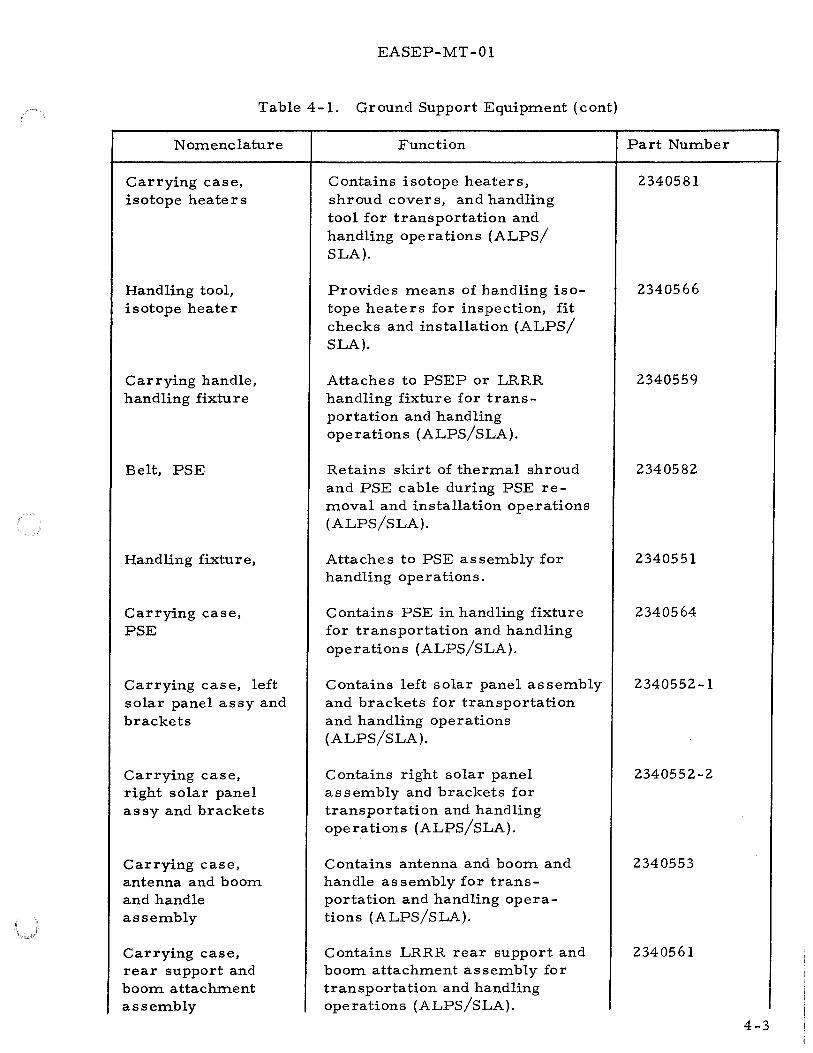
EASEP-MT-01
Table 4-1. Ground Support Equipment ( cont}
Nomenclature
Carrying case, isotope heaters
Handling tool, isotope heater
Carrying handle, handling fixture
Belt, PSE
Handling fixture,
Carrying case, PSE
Carrying case, left solar panel assy and brackets
Carrying case, right solar panel assy and brackets
Carrying case, antenna and boom and handle assembly
Carrying case, rear support and boom attachment assembly
Function
Contains isotope heaters, shroud covers, and handling tool for transportation and handling operations (ALPS/ SLA}.
Provides means of handling isotope heaters for inspection, fit checks and installation (ALPS/ SLA}.
Attaches to PSEP or LRRR handling fixture for transportation and handling operations (ALPS/SLA}.
Retains skirt of thermal shroud and PSE cable during PSE removal and installation operations (ALPS/SLA}.
Attaches to PSE assembly for handling operations.
Contains PSE in handling fixture for transportation and handling operations (ALPS/SLA}.
Contains left solar panel assembly and brackets for transportation and handling operations {ALPS/SLA}.
Contains right solar panel assembly and brackets for transportation and handling operations (ALPS/SLA}.
Contains antenna and boom and handle assembly for transportation and handling operations (ALPS/SLA}.
Contains LRRR rear support and boom attachment assembly for transportation and handling operations (ALPS/SLA}.
Part Number
2340581
2340566
2340559
2340582
2340551
2340564
2340552-1
2340552-2
2340553
2340561
4-3

EASEP-MT-01
Table 4-1. Ground Support Equipment ( cont}
Nomenclature
Sling assembly
Sling assembly
Shipping container, PSEP experiment
Shipping container, LRRR experiment assembly
Shipping can, radioisotopic heater
Outer shipping container, radioisotopic heater
Shipping container, radioisotopic heater
Hoisting device, monorail
Auxiliary scientific equipment support
4-4
Function
Attaches to handling fixture for hoisting LRRR or PSEP in horizontal attitude (ALPS/SLA}.
Attaches to handling fixture carrying handle for hoisting LRRR or PSEP in vertical attitude (ALPS/SLA}.
Provides physical protection and controlled environment for shipment of PSEP to KSC.
Provides physical protection and controlled environment for shipment of LRRR to KSC.
Provides physical protection for radioisotopic heater during shipment to, and storage at KSC.
Provides physical protection for shipment of radioisotopic heater to KSC.
Provides physical protection and thermal insulation for shipment of radiosotopic heater to KSC.
Provides means of hoisting EASEP subassemblies in GSE to XA 525 level in SLA.
Provides means for alignment of EASEP packages with rails of SEQ bay for installation.
Part Number
2340585
2340586
2340556
2340599
4-8028 (Monsanto}
3-6938 (Monsanto}
3-6945 (Monsanto}
(GAEC}
LDW-420-11171-1 (GAEC}
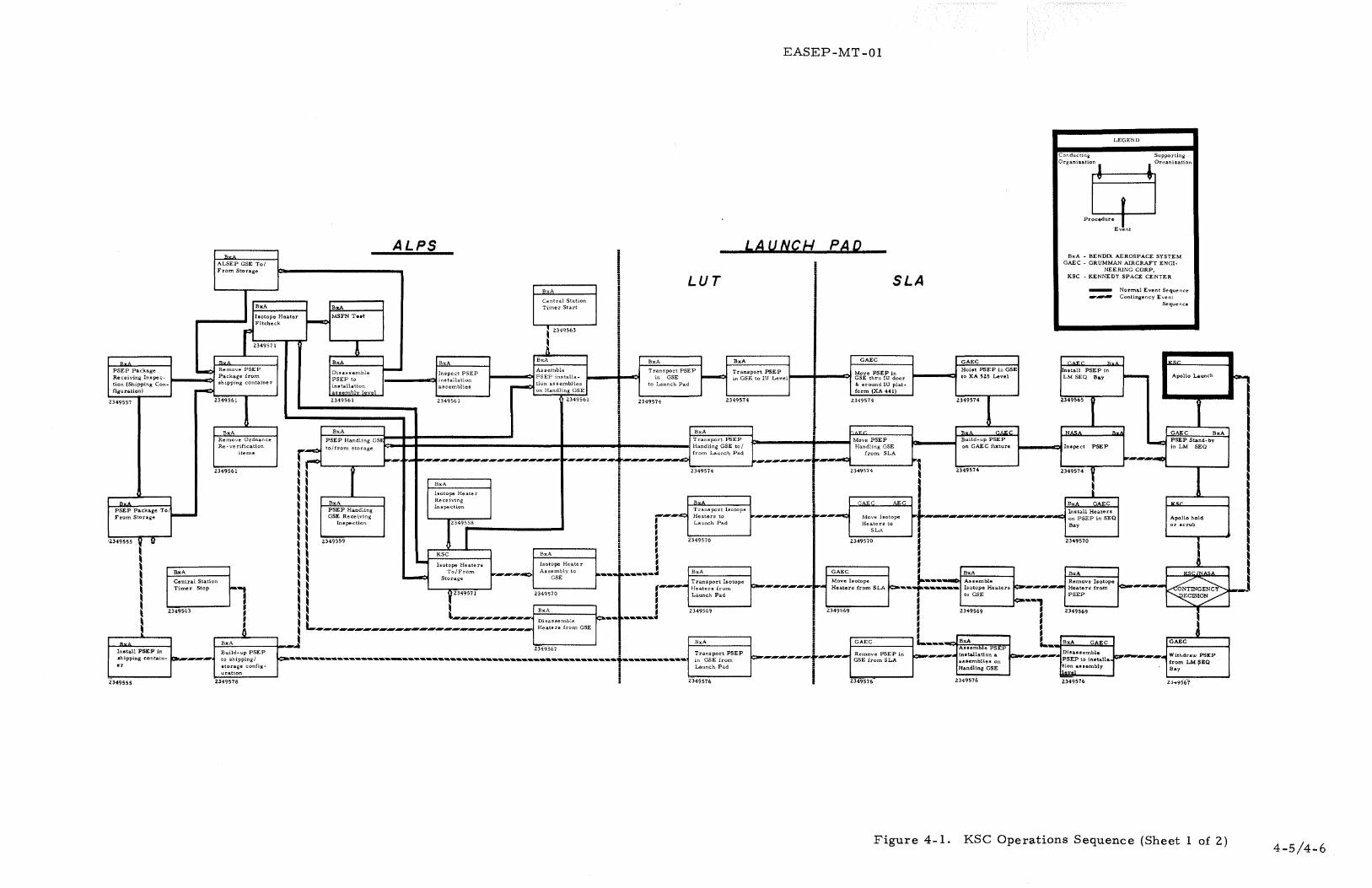
EASEP-MT-01
LEGEND
Conducting Supporting
o., .. , .. ~CJjo"'"'"""' Event
ALPS LA UNCI-I PAD BxA BxA - BENDIX AEROSPACE SYSTEM
ALSEP GSE To/ GAEC - GRUMMAN AIRCRAFT ENGI-
From Storage NEERING CORP,
LUT SLA KSC -KENNEDY SPACE CENTER
BxA - Normal Event Sequence
Central Station -- Contingency Event
BxA BxA Timer Start Sequence
Isotope Heater ~
MSFN T .. t Fitcheck r Z349571
' Z349563
A ! s, s, BxA BxA
BxA BxA BxA GAEC GAEC r.AW'.r " LKsc PSEP Package ~ Remove PSEP
Disassemble - Assemble i Transport PSEP Transport PSEP Move PSEP in Hoist PSEP in GSE Install PSEP in Inspect PSEP
~ ~ Apollo Launch Receiving Inspec- Package from PSEP to installation
PSEP installa- in GSE in GSE to IU Level GSE thru !U door to XA SZS Level LM SEQ B&y tion (Shipping Con- shipping container
installation assemblies ~ tion assemblies I to Launch Pad & around IU plat-
figuration) ~ assemblv level on Handling GSE form (XA 441)
.2349557 Z349561 I 2349561 2349561 2349561
i 2349574 2349574 2349574 Z349574 1 Z349565 I
• i
BxA BxA ! BxA .. ,, "' GAEC NA<• "' GAEC BxA Remove Ordnance PSEP Handling GS i Transport PSEP Move PSEP Build-up PSEP -PSEP Stand- by Re-verification r-:. to/from storage Handling GSE to I Handling GSE on GAE C fixture Inspect PSEP in LM SEQ
item a
~-----~..:.. ............................... ~ from Launch Pad from SLA .............. ~ :r -- ·- 'r""--.................................................................................. ............................ ..,,.,., ~r--.-c:l "'1 Z349561
J 2349574 I 2349574
~ 2349574 2349574 y
H BxA I H
Isotope Heater I I s, BxA Receiving s, • GAEC AEC BxA GAEC KM:
PSEP Package To PSEP Handling Inspection Transport Isotope - H ,... .......... ~ ~---.:l ~ ..... ..-.-. .......................................................... ..-c;~
Install Heaters From Storage GSE Rece~ving Heaters to ........ -----..,. Move Isotope on PSEP in SEQ Apollo hold
Inspection r·T· I Launch Pad Heaters to Bay or scrub
H I SLA
'Z349555 .y 11 p 2349559
I 2349570 2349570 .2349570 I I KSC BxA I d - I i
I Isotope Heaters Isotope Heater • I BxA To/From ................... ......:> Assembly to BxA GAEC ~ BxA BxA KSCLNASA
GSE p ~ .. ._,... __ .__ .......
d ~......::> Storage Move Isotope 1----~ Assemble I Central Station .,...,. Transport Isotope ~ .............................. Remove Isotope
~rnGb Heaters from SLA r=:---.-..,..---.--~ Isotope Heaters ~..,....,....,....,..,. ~----
~ ~~ L _________ f-"B'-'!:.xA'----L_ ... f ............... J Timer Stop
I 2349563
Install PSEP in shipping contain- ca,.r .... ...,...-r.
2:349555
~, p YZ349571 2349570 ,....,..._..~ Heaters from
~ Launch Pad
2349569
II' ~ ~ Disassemble A ~ L.,.,.. .... ..,.....,. __ ...,...,....,...,. ...... ...,.....-..-.,..,._.....-...,....,... ...... ...,....,....,....,...,...,......., Heaters from GSE
1--'B~x~A::,_ ____ -j....-J Z349S67 I BxA
Build-up PSEP to shipping/ .:;:...__._._.,._._._._.,.,_.__.__ .. .....,_._.._. _________ ._._. __ .__._._.,., _______ .__.,.,.,._._;_.__.,._._.__._.__
storage config· 1
Transport PSEP in GSE from Launch Pad
23~;~~i=n I 2349576
!r•
Remove PSEP in GSE from SLA
2349576
~ to GSE
' fc-••
2349576
Heaters from PSEP
2349569
tion assembly level
.2349576
ECISION
GAEC
Withdraw PSEP from LMSEQ Bay .
Figure 4-1. KSC Operations Sequence (Sheet 1 of 2)
:c:-
I
~J
4-5/4-6


BxA
LRRR Receiving Inspection (Ship-ping Configura-tion)
Z349556
Bx_A LRRR To/From Storage
i349554 r ! I I I I
ln1taU LRRR in •hipplna contaln•r
BxA
Remove LRRR - from shipping container
~ Z349560
.BxA ALSEP GSE To/ -- l'rom Storage
-
BxA
Dlla•semble LRR.R to in1tal-lation &I 1embly leTel
Z349560
BxA LRRR Handling GSE Receiving
Inspection
ALPS
lixA BxA
as•emblies
i BxA
Transport LRRR in GSE to Launch Pad
EASEP-MT-01
LAUNCJ-1 PAD
LUT SLA
BxA GAEC - Transporf LRRR Move LRRR in
in GSE to tu Level ! GSE thru IU door and around IU
GAEC Hoilt LRRR in GSE to XA525
Level
LEGEND
Conducting Supporting
Organizatil±===flganization
PrU-J Event
BxA-Bendix Aeroa~pace Systems ~AEC- Grumman Aircraft
Engineering Corp. KSC- Kennedy Space Center
-----•Normal event sequem.e . . .,_.,..,.,,.,...,.~ Contingency event
sequence
r.ur "· IKSr
In•tall LRRR in 1M SEQ ~ Apollo Launch
Bay - ' ' 2349573 !
l I Z349560 Z349573 Z349560
platform (XA<Wl)
2349573 Z349573 1 Z349564l
~, .. ..,_.. I I I I I
' ' i ""''" BxA
Transport LRRR Move LRRR
! Handling GSE i Handling GSE
r~___.,...,...,.-1--...,.....::>....,t_o_/f.;.;;;;.a':.;._L_a_u_nc-h-..ti--•.------------+---._'_o_/f-ro-m-.--SL-A---'
B• GAE.C._
Build .. up LRRR on GAEC fixture
·~·
1----tr:>t ln•pect LRRR
I l Zl49575 • Z3495751
·~ I I ~ I I "~" " .._ ___ ~LRRR Handling GSE- ~ !"'"~-- Transport Shadow • ~ • .- - -· -- · · Sh d
2349573 '
I 2349573
r" to/from storage r--- ; ~ 1 Plates to/ ~..,....,...,....,..,......,. ..... ..,.....,....,.....,..~...,..1""...,.....,.....,.....,......,.___.__,.~...,.....,....,..,..-...,....,....,.._______ Move Shadow Plate•':--.,.......,..._ Replace a 0 W.
._,.... _____ ... ~--·· ................................. ~ I II r-- from La~nch Pad p-------------i-------+--------.. to/from SLA c------.,.,.P,..Ia-to_·..,,....--..
~ I I Z349568 I Z349568 Z349568 v I Ill ~ ~ I II! I L-----------., ; i B;:,adow Plaieo J ~ ~ ~~,~~raw LRR.s;
- GAEC Bx.< LRRR Stand .. by in LM SEQ B&y
KSC Apollo Hold
or Scrub
I I I I I I I -"' i to/from otorage P-fl ~ ~ from LM SEQ Bay jc::a----
i Z349568 I I Z349566 L--...;:,.-=:;....-...1
I II I 1 ~~"-~---,==-.;..-. ....... -.._ ... -..1 i J.=B:;x::,A:__-.,.,=:--1 GAEC xA GAEC BxA GAEC GAEC BzA
• Transport LRRR in Remove LRRR 1111emble LRRR Disassemble LRRR
Z349577
:.tl"....,....,....,....,.....,.,._....,....,....,....,....,....,....,....,.....,...,....,....,....,...,....,....,....,....,...,.+...,.~psE from Launch c::a---..,.....,...,....,.....,...,....,...,....,....,....,...,.+...,....,....,. ... in GSE from SLA ...,.....,...,...-.: ::t:!:~:: on ,_....,......,....,..,. ~~..,......-..~
i - ' ~~ I ... .,. I , ... " ... .,. 2349575
Withdraw LR.R.R. from LM. SEQ
Bay
Z349566
Figure 4-1. KSC Operations Sequence (Sheet 2 of 2) 4-7/4-8


EASEP-MT-01
HOISTING DEVICE
~
~'; ~~ ~--- ~~ -~ HANDLING DEVICE
ITYPICAU
HANDLING CART
Figure 4-2. EASEP Package Handling GSE
4-9

PSE BELT
EASEP-MT -01
PROTECTIVE COVER (TYPICAU
PSE CARRYING ISOTOPE HEATER CASE HANDLING TOOL
Figure 4-3. Assembly Handling GSE {Sheet 1 of 2)
4-10

SLING ASSEMBLY 2340586
EASEP-MT-01
HANDliNG FIXTURE (TYPICAL)
SLING ASSEMBLY 2340585
Figure 4-3. Assembly Handling GSE (Sheet 2 of 2)
HANDliNG FIXTURE CARRYING HANDLE
4-ll

EASEP-MT -01
4-4. LUNAR SURF ACE OPERATIONS
Lunar environmental conditions impose constraints on EASEP hardware and its deployment by the astronaut. EASEP deployment procedures will be performed at a time when the sun angle from the lunar horizon is 7 to 22 degrees. At a sun angle of 7 degrees, the lunar surface temperature is approximately -50 to -60 degrees F. At a sun angle of 22 degrees, the lunar temperature is +80 to +100 degrees F. EASEP design allows deployment at a maximum sun angle of 45 degrees and a relative lunar surface temperature of approximately +165 degrees F.
The following paragraphs describe the events that take place from the time the LM lands on the lunar surface until the EASEP packages have been deployed. Included in the discussion are:
a. Flight mode - The in-flight configuration of EASEP. b. Handling mode - The activity performed by the astronaut in removing the
EASEP packages from the LM and transporting them to the emplacement area. c. Deployment - The events performed by the astronaut in emplacing the
EASEP packages.
The lunar surface operations as presented here reflect a combination deployment procedure where both packages are removed from theLM and deployed at the same time. Either package can be removed and deployed independently of the other. No order of priority as to which package is deployed first has been established.
4-5. FLIGHT MODE
During flight, the EASEP packages are inert except for the heat dissipation of the isotope heaters on PSEP.
The LRRR and PSEP are secured by retaining pins in separate compartments of the LM SEQ bay. The SEQ bay location in the LM descent stage is illustrated in Figure 1-1.
4-6. HANDLING MODE
The handling mode encompasses the tasks of removing the LRRR and PSEP from the LM SEQ bay, and traversing to the emplacement area.
4-12

EASEP-MT-01
Figure 4-4. Shipping Container
The basic handling mode events, in chronological order, are:
a. Descent to lunar surface b. Walk to descent stage stowage compartment (SEQ) c. Unload EASEP packages d. Locate correct traverse bearing e. Walk 32 feet at selected bearing carrying packages.
PACKAGE CONTAINER ITYPICAU
4-7. Descent to Lunar Surface. The handling mode begins with the astronaut descending from the LM to the lunar surface.
4-13

SHIPPING CAN
OUTER SHIPPING CONTAINER
EASEP-MT-01
SHIPPING CONTAINER
Figure 4-5. Radioisotopic Heater Shipping Containers
4-8. Remove EASEP packages from the LM. The astronaut walks to the LM SEQ bay, releases and raises the thermal door. The astronaut retrieves the LRRR deployment lanyard, walks 10 feet from LM, pulls deployment lanyard to release LRRR tie-downs and extend boom, lowers LRRR to the lunar surface, releases velcro and pulls lanyard to separate boom assembly from boom attachment assembly, and restows the boom. The astronaut then retrieves the PSEP deployment lanyard, walks 10 feet from LM, pulls deployment lanyard to release PSEP tie-downs and extend boom, lowers PSEP to lunar surface, pulls pin to release deployment handle and separate boom attachment assembly from PSEP, extends handle to 30-inch working height and rotates it 90 o to lock in place, restows boom and deployment lanyard, and closes SEQ bay door.
4-9. Transport EASEP Packages to Emplacement Area. The astronaut lifts the PSEP and LRRR from the lunar surface using the carry handles as shown in Figures 4-6 and 4-7. He then walks to the LM- Y axis landing gear pad and surveys the lunar surface to select a suitable deployment site. He then walks approximately 32 feet from LM to selected site and lowers the EASEP packages to the surface on aN-Saxis.
4-14

EASEP-MT-01
Figure 4-6. Astronaut Carrying PSEP
4-15

EASEP-MT- 01
Figure 4-7. Astronaut Carrying LRRR
4-16

EASEP-MT- 01
4-10. DEPLOYMENT OF LRRR
Performing the deploytnent sequence, the astronaut:
a. Positions the LRRR on anE-W axis, b. pulls pin, and removes boom attachment assembly from LRRR, c. pulls alignment handle to extend 6 inches, partially releasing retro-reflector
array, d. detaches velcro, and pulls cover release lanyard to separate cover from
array assembly, e. rotates aiming handle 45° and extends it to the detent position to completely
release array, f. observes index marks on the angle indicator as he tilts the array to the
angle of the selected site, using aiming handle. (See Figure 4-8.) g. extends alignment handle an additional 27 inches and uses handle to rotate
LRRR 90° so that the pallet lies flat on the lunar surface, (See Figure 4-9.) h. observes bubble level and shadow cast by the gnomon on sun compass
plate as he levels and aligns the LRRR to within± 5o of the appropriate sun compass reference mark, using alignment handle.
4-11. DEPLOYMENT OF PSEP
Performing the deployment sequence, the astronaut:
a. Positions PSEP 10 feet north or south of the LRRR on an E-W axis with the bottom of pallet facing northward, (See Figure 4-10.)
b. pulls lanyard to release gnomon, then rotates gnomon to elevated position, c. removes solar panel pull pins and front, and rear supports, d. rotates PSEP 90° using carry handle so that pallet lies flat on lunar
surface, e. uses deployment handle to align PSEP to within± 5o of PSEP centerline while
observing ball level and shadow cast by gnomon on the compass rose, f. pulls antenna/ solar panel release lanyard to deploy antenna and solar
panels, g. rotates antenna to elevation of selected site while observing antenna tilt
angle indicator and pointer. (See Figure 4-11.)
4-12. POST-DEPLOYMENT OPERATIONS
Communication between MCC-H and PSEP passive seismic experiment package is established with the activation of the central station by solar energy. For two 14-day periods, PSEP (lunar day operation) is monitored continuously. Commands which initiate specific actions required for normal operation are sent to PSEP during this period. Commands are also sent to change or request status of PSEP.
4-17

EASEP-MT- 01
Figure 4-8. Astronaut Deploying LRRR
4-18

EASEP-MT-01
'1:1 (I)
:>. 0 ...... p.. (I)
Q p::; p::; p::; ...:1
a-I ~
(I) 1-1 p btl
•r-1
~
I
I I !
4-19

EASEP-MT- 01
Figure 4-10 Astronaut Deploying PSEP
4-20

EASEP-MT- 01
I I I I I 1 j j
I 4-21 I

EASEP-MT- 01
PSEP transmission (downlink) is received by remote sites on Earth and relayed to MCC-H via tie line cables. Commands initiated by MCC-H are routed through another tie line cable to the remote site and are transmitted to PSEP. This communication system is referred to as the manned space flight network (MSFN).
Because of the Earth's rotation, it is necessary to establish remote sites around the Earth. Remote sites for PSEP will be selected from the following:
a. Goldstone, California (85-foot antenna) b. Carnarvon, Australia (30-foot antenna) c. Canberra,· Australia (85-foot antenna) d. Ascension Island ( 30-foot antenna) e. Hawaii (30-foot antenna) f. Guam ( 30-foot antenna) g. Madrid, Spain (30- and 85-foot antennas).
At MCC-H the telemetry data are decoded by the computer control and telemetry system (CCATS) and fed into another computer where they are assimilated and routed to display in the LM staff support room (SSR) and the experiments room.
Principal investigators (PI) observe the display in the experiments room and make preliminary evaluations. The PI may advise the EASEP controller concerning problems with his experiment. After evaluating data, in near real time, the PI may suggest changes to the command procedure in order to gain additional data.
4-15. Uplink Transmission. Commands are generated by the console controller at the console command keyboard. The generated signal is routed through the command computer where it is programmed and routed over the tie line cable to GSFC. At GSFC the transmission is switched to another tie line cable and routed to the applicable switching station (Hawaii or London). The switching station routes the transmission to the applicable remote site. At the remote site, the command transmission is fed into a computer for formatting. The output of the computer is connected to the remote site transmitter and the command is transmitted to EASEP.
The stations selected will provide transmitters /receivers in latitude about the equator ranging from approximately 34 degrees north to 25 degrees south. It is probable that four receivers will be located in the northern hemisphere and two in the southern hemisphere.
The 30-foot dish antennas can be used for normal operations, but the 85-foot dish antennas will be used in the event that PSEP antenna aim-angle is in error.
4-13. MANNED SPACE FLIGHT NETWORK (MSFN)
Typical MSFN and MCC-H EASEP operations are described in the following paragraphs. Because specific responsibilities have not been defined, the description is typical only.
4-22

EASEP-MT-01
4-14. Downlink Transmission. Figure 4-12 provides a block diagram illustrating the EASEP functions of MSFN. Telemetry data (engineering status and scientific data) are transmitted by EASEP and received by the remote site 30- or 85 -foot dish antennas. The signal is routed from the antenna to the receiver rf detection stage. The signal (T /M bit stream) from the detector stage is tape recorded as a backup in event the 14-channel tape recorder or receiver are inoperative. This tape is reused. The rf signal output from the detector stage is demodulated and routed to the site computer and to a 14-channel tape recorder. All EASEP data are recorded on this tape recorder for the full year regardless of whether MCC -H is monitoring or not. The audio frequency bit stream is recorded on one channel of the 14-channel tape recorder. Another channel is used to automatically record the time -of -day (Greenwich mean time). A third channel is used to insert voice annotations as required. This includes information pertinent to the recorded data (description of station abnormalities, time or signal gaps not caused by EASEP.
TELEMETRY (DOWNLINK) ___________ ...__
MCC-H
r--,-----, I DISPLAY I L-
_ _.
L---
COMMAND (UPLINK)
,-coMMAND,
L~!..B!'~~ ..
REMOTE SITE r-'-------------1 I I I I I I I I I
UPLINK
r--- ---, I RF I L- ~!EC~~- .J
COMPUTER
.----- ---, I DEMODULATION. t-1-&...4-t TAPE RECORDER
RECEIVER
TAPE RECORDER VOICE AND TIME
INSERTION
L-------------------,
COMMAND I UPLINK -COMPUTER I I I ~ I I
DOWNLINK J -------- - ___ ,_,
..., I I I I I I I I I I _______ ,..~
' tTIE LINE CABLE
Figure 4-12. MSFN Functional Block Diagram
4-23

EASEP-MT -01
The 14-channel tape recorder is operated at 3-3/4 ips. When the recorder spool is expended, the tape is removed and shipped to NASA-Houston where it is converted to machine language for subsequent detailed analyses. When required, another tape recorder is connected into the same line and is started prior to shutting off the first recorder. This provides an overlap of the bit stream rather than a loss of data.
The modulated signal input to the site computer is encoded to format, supplied with a header (shows routing and address), and processed through the tie line cable. The computer process of converting the data to format and inserting the header results in a slight delay; therefore, the data processed over the tie line cable is not quite in real time. The tie line cable has a capacity of 2400 bps.
The tie line cable carrying the telemetry data terminates at a switching station (London or Hawaii) where the transmission is switched to another tie line cable and routed to the Goddard Space Flight Center (GSFC ). At GSFC the switching procedure is repeated and the telemetry data are routed to MCC-H.
At MCC-H the telemetry data are decoded by the computer control and telemetry system ( CCA TS) and fed into another computer where they are assimilated and routed to display in the LM staff support room (SSR) and the experiments room.
Principal investigators (PI) observe the display in the experiments room and make preliminary evaluations. The PI may advise the EASEP controller concerning problems with his experiment. After evaluating data, in near real time, the PI may suggest changes to the command procedure in order to gain additional data.
4-15. Uplink Transmission. Commands are generated by the console controller at the console command keyboard. The generated signal is routed through the command computer where it is programmed and routed over the tie line cable to GSFC. At GSFC the transmission is switched to another tie line cable and routed to the applicable switching station (Hawaii or London). The switching station routes the transmission to the applicable remote site. At the remote site, the command transmission is fed into a computer for formatting. The output of the computer is connected to the remote site transmitter and the command is transmitted to EASEP.
4-16. MCC-H Operation. The PSEP console controller initiates commands to PSEP using the command keyboard. Telemetry data received from PSEP are displayed on the console. As data are received, the controller evaluates the status of PSEP and generates corrective commands as required. For example, PSEP may stop transmitting modulation on the carrier in which case the controller would probably issue a command for PSEP to switch data processors.
The PSEP console controller also inserts commands required for the normal operation of PSEP. (Refer to Appendix for a complete list of the normal commands).
4-24
EASEP-MT -01
As PSEP transmits engineering and scientific data back to Earth, the controller must evaluate the status of PSEP through interpretation of the data display. Depending on detail requirements and specific mechanization, the displays may include TV (charactron) formats, page printers, meters, X- Y plotters, analog strip charts, and event lights. The computer handling these displays can insert sensor calibration data, compare them against preset limit values, and perform other analysis functions.
4-25/4-26


Abbreviation
AjD
AFCRL
ALPS
ALSEP
BxA
CFE
CM
cs DS/S
EASEP
EMU
EPS
FET
GAEC
GFE
GHz
GSE
IBM
IU
Hz
KHz
KSC
LM
LP
LPOP
LRRR
LUT
MCC-H
MSC
EASEP-MT-01
GLOSSARY
Definition
Analog to Digital
Air Force Cambridge Research Laboratory
ALSEP Launch Preparation Site
Apollo Lunar Surface Experiments Package
Bendix Aerospace Systems Division
Contractor Furnished Equipment
Command Module
Central Station
Data Subsystem
Early Apollo Scientific Experiments Payload
Extravehicular Mobility Unit
Electrical Power Subsystem
Field Effect Transistor
Grumman Aircraft Engineering Corporation
Government Furnished Equipment
Gigahertz
Ground Support Equipment
International Business Machines
Instrument Unit
Hertz; Cycles per Second
Kilohertz
Kennedy Space Center, Florida
Lunar Module
Long Period
LM Pre-Flight Operations Procedure
Laser Ranging Retro -Reflector Experiment
Launch Umbilical Tower
Mission Control Center -Houston
Manned Spacecraft Center
G-1

G-2
MSFN
MSOB
NASA
NRZ
PAM
PCM
PCU
PDU
PI
PSE
PSEP
QA
RF
RFI
SEQ
SLA
SM
SP
TCP
USGS
VAB
EASEP-MT-01
GLOSSARY (Cant)
Manned Space Flight Network
Manned Spacecraft Operation Building
National Aeronautics and Space Administration
Non Return to Zero
Pulse Amplitude Modulation
Pulse Coded Modulation
Power Conditioning Unit
Power Distribution Unit
Principal Investigator
Passive Seismic Experiment
Passive Seismic Experiment Package
Quality Assurance
Radio Frequency
Radio Frequency Interference
Scientific Equipment Bay in LM
Spacecraft LM Adapter
Service Module
Short Period
Test Checkout Procedure
United States Geologic Survey
Vehicle Assembly Building

EASEP-MT-01
APPENDIX A
COMMAND LIST

EASEP-MT-01
INTRODUCTION
This appendix presents the current inventory of commands applicable to the Passive Seismic Experiment Package. The initial issue has been revised in the following areas :
a. The annotation of the preset condition of certain commandable functions reflect the initial functional mode defined in the PSEP preliminary operational plan (EATM-38).
b. The significance of the High Data Rate command (CD-31) in inhibiting all data output has been flagged.
c. The classification of the commands has been expanded to identify those commands which are not significant in the operation of PSEP in the following groups.
those which control power distribution functions which were in the ALSEP 2 central station but have been deleted from PSEP
- those which are assigned to control functions in experiments which are not provided
Table 1 lists the commands by symbol, nomenclature, number, and termination point. Table 2 provides a summary of command allocation. Table 3 crossreferences command numbers and command functions.
The following notes are relevant to the data in each table as referenced:
Note 1 Operational mode inherent in equipment at power turn-on
Note 2 Operational mode preset during flight preparation
Note 3 Will inhibit all data output
Note 4 Will not alter functional mode (housekeeping status may change)
Note 5 Changes bit rate upon command execution
Note 6 Changes bit rate at end of data frame during which the command is executed
Note 7 Manual leveling sequence is as follows: Send CL-15 to change auto to manual leveling mode, change direction, and speed by CL-10 and CL-11
A-I

A-2
EASEP -MT -01
as necessary, and then leveling operating by sending appropriate leveling motor commands, CL-6, CL-7, or CL-8. Leveling operation is terminated by retransmission of CL-6, CL-7, or CL-8.
Note 8 Sequence of command is auto on1 /auto off/manual on/manual off.

TABLE 1
Octal Decimal Symbol Command Nomenclature Command Command Termination Point Notes -CD-31 ASE High Bit Rate ON 003 3 Data Processor 3, 6
CD-32 ASE High Bit Rate OFF 005 5 II II 1
CD-33 Normal Bit Rate 1
006 6 II II 1
CD-34 Slow Bit Rate 007 7 II II
CD-35 Normal Bit Rate Res, t 011 9 II II 5
CD-1 Transmitter "A" Seh.:ct 012 10 Power Dist. Unit 2
CD-2 Transmitter ON 013 11 II II II t:r:1 - > CD-3 Transmitter OFF 014 12 II II II
(/l
2 t:r:1 'U
CD-4 Transmitter "B" Select 015 13 II II II - ~ CD-5 PDR #1 ON 017 15 II II " - ~
I 0
CD-6 PDR #1 OFF 021 17 II " II 2 .....
CD-7 PDR #2 ON 022 18 II II II
CD-8 PDR #2 OFF 023 19 II II II 2
CD-9 DSS HTR 3 ON 024 20 II II II 4
CD-10 DSS HTR 3 OFF 025 21 II II II 2
CD-11 Data Processor "X" Select 034 28 II II II 2
CD-12 Data Processor "Y" Select 035 29 II II II
CD-13 Experiment 1 Operational Power ON 036 30 II II II
CD-14 Experiment 1 Standby Power 037 31 II II II 2
> I w

> I
"""' TABLE 1 {CONT.)
Octal Decimal Symbol Command Nomenclature Command Command Termination Point Notes
CD-15 Experiment 1 Standby OFF 041 33 Power Dist. Unit
CD-16 Experiment 2 Operational Power ON 042 34 II II II 4
CD-17 Experiment 2 Standby Power 043 35 II II II 4
CD-18 Experiment 2 Standby OFF 044 36 II II II 2, 4
CD-19 Experiment 3 Operational Power ON 045 37 II II II 4
CD-20 Experiment 3 Standby Power 046 38 II II II 4
CD-21 Experiment 3 Standby OFF 050 40 II " " 2, 4
CD-22 Experiment 4 Operational Power ON 052 42 II II II 4
CD-23 Experiment 4 Standby Power 053 43 II II II 4
CD-24 Experiment 4 Standby OFF 054 tr.!
44 II II II 2, 4 > (/l
CD-25 DSS HTR 1 Select 055 45 II II II 4 tr:l 1::1
CD-26 DSS HTR 2 Select 056 46 I
II II II 4 ~ CD-27 DSS HTR 2 OFF
t-3 057 47 II II II 2, 4 I
0
CD-36 .......
Timer Output Accept 032 26 Command Decoder 1
CD-37 Timer Output Inhibit 033 27 II II
CU-1 PCU #1 Select 060 48 Power Cond. Unit 2
CU-2 PCU #2 Select 062 50 II II II

:> I Ul
Symbol
CL-1
CL-2
CL-3
CL-4
CL-5
CL-6
CL-7
CL-8
CL-9
CL-10
CL-11
TABLE 1 (CONT.)
Octal Command Nomenclature Command
Gain Change LPX, LPY 063 (Steps through following sequence one step per command)
-30 db1
0 db -10 db -20 db
Gain Change LPZ 064 (Steps through same sequence as
CL-1)
Calibration SP ON /OFF1
065
Calibration LP ON/OFF1
066
Gain Change SP Z 067 {Steps through same sequence as CL-1)
Leveling Power X Motor ON/OFF1
070
Leveling Power Y Motor ON/OFF1
071
Leveling Power Z Motor ON/OFF1
072
Uncage Arm/Fire 073
Leveling Direction Plus 1
/Minus 074
Leveling Speed Low1
/High 075
Decimal Command Termination Point Notes
51 Passive Seismic Exp.
1
52 II II II 1 M :> CJl M
53 II II 11 1 1:l I
~ 54 11 11 11 1 t-3
I
55 Passive Seismic Exp. 1 0 ......
56 II 11 11 1, 7
57 11 11 11 1, 7
58 11 11 II 1, 7
59 II 11 11
60 II 11 II 1, 7
61 11 II 11 1, 7

~ I 0'
Slmbol
CL-12
CL-13
CL-14
CL-15
CX-1
CX-2
Command Nomenclature
Thermal Control Mode
Feedback Filter
Coarse Level Sensor
Leveling Mode
Dust Detector - ON
Dust Detector - OFF
TABLE l (CONT.}
Octal Command
l Auto /Manual 076
IN/OUT1
101
IN/OUT1
102 l
Auto /Manual 103
027
031
Decimal Command
62
65
66
67
023
025
Termination Point Notes
Passive Seismic Exp. 1, 8
II II
II II
II II
Power Dist. Unit
Power Dist. Unit
II
II
II
1
1
1, 7
2
~ 1?=:1 1:1 I
~ 1-:] I 0
"'""

EASEP-MT-01
TABLE 2
COMMAND DISTRIBUTION
2a PSEP Commands
Termination Point
Data Processor Power Distribt1tion Unit (Power Switching) Power Conditioning Unit Command Decoder Passive Seismic
Total
Zb Special Commands - Not Assignable
Number of Commands
3 15
2 2
15
37
Function Octal Code Number
Test Commands 1, 2, 4, 10, 20, 40 14 100, 77, 137, 157, 167, 173, 175, 176
Address 130, 30, 116, 16, 151, 5l):C 6
Address Complement 47, 147, 61, 161, 26, 126t.c* 6
No Command 0, 177 2
Total
2c Summary
Commands Assigned to PSEP Commands Assigned to ALSEP Commands Not Assignable Commands Not Presently Assigned
Total Commands
*Addresses for EASEP are 116, 16. **Address Complements for EASEP are 61 and 161.
28
37 55 28
8
128
A-7

:;t> I TABLE 3 00
CROSS REFERENCE OF COMMAND NUMBER TO COMMAND FUNCTION
>-.. 0 ':jj s:: f-1 s:: (!) (!)
Cll Cll a -gp.. Cll"Cl Cll Cll (!)
(!) (!)
(!) (1)..-4 S::Jil $.1 s:: $.1 $.1 p.. .~ Cl) p.. .~
Decimal Octal Command Test I "Cl "Cl a Cll ...:1 .. Cll "Cl "Cl 0 Cll< 0 Cll
Command Command S mbol PSEP Cmds. < <U < Z<
1 1 X
2 2 X
3 3 CD-31 (See Note 3) I I lx 4 4 X
5 5 CD-32 I I lx 6 6 CD-33 X
7 7 CD-34 X
8 10 X
9 11 CD-35 X M
10 12 CD-1 X ~ 11 13 CD-2 X M
12 14 CD-3 X ~ I
13 15 CD-4 X ~
14 16 X t-3 I 0
15 17 CD-5 X ..... 16 20 X
17 21 CD-6 X 18 22 CD-7 X 19 23 CD-8 X 20 24 CD-9 (See Note 4) I~ 21 25 CD-10 (See Note 4)
22 26 X

TABLE 3 {CONT.)
>-+> 0 ...-1 c +>
E-1 s:: Q) Q)
Ul Ul E "tt Ul'tj Ul Ul Q) ~~ Q) Q) Q) Q)~ 1-4 s:: 1-4 1-4 p.. bl)~ ~bl)
"tt E •.-1 f./'J •.-1 Decimal Octal Command Test "tt ~ ...:t +> Ul "tt "tt 0 0 Ul Command Command Symbol PSEP Cmds. ~ ~l) ~~ Z5
23 27 CX-1 X 24 30 I IX 25 31 CX-2 X 26 32 CD-36 X 27 33 CD-37 X
M 28 34 CD-11 X > 29 35 CD-12 X (Jl
1::! 30 36 CD-13 X '"d I 31 37 CD-14 X ~ 32 40 X 1-3 I 33 41 CD-15 X 0 ..... 34 42 CD-16 (See Note 4) X
35 43 CD-17 {See Note 4) X 36 44 CD-18 (See Note 4) -" X 37 45 CD-19 (See Note 4) X 38 46 CD-20 {See Note 4} X 39 47
X 40 50 CD-21 {See Note 4} IX 41 51 X 42 52 CD-22 (See Note 4) X 43 53 CD-23 (See Note 4) X 44 54 CD-24 (See Note 4} X 45 55 CD-25 (See Note 4} X 46 t)6 CD~26 (See Note 4} X
> I
...0

> I -0
Decimal Command
47 48 49 50 51 52 53 54 55 56 57 58 59 60 61 62 63 64 65 66 67 68
Octal Command
57 60 61 62 63 64 65 66 67 70 71 72 73 74 75 76 77
100 101 102 103 104
TABLE 3 (CONT.)
Command Symbol PSEP
CD-27 (See Note 4) CU-1 X
CU-2 X CL-1 X CL-2 X CL-3 X CL-4 X CL-5 X CL-6 X CL-7 X CL-8 X
CL-9 X CL-10 X CL-11 X CL-12 X
CL-13 X CL-14 X CL-15 X
>-~ 0 .-I
Q E-r ~ Q) Q)
Cl) Cl) E "C Cll"C Q) Q) v
Cl) Cl) Q) l=lP.. ,... Q Q) v.....t ,... ,... 0.. tlOJ:il p.. .~
Test "C "C E ·u; U) ~ Cl)
"C "C 0 Cl)~ 0 Cl)
Cmds. < <U << Z<
X
I I I X
M > Cll M 1:1 I
~ 1-3 I 0 .....
I X X
I I I lx

TABLE 3 (CONT.)
>-~ 0 -Q ~
f-1 s:: Q) Q)
Cll Cll a "Cl Cll"d
~~ Q) Q)
Cll Cll Q)
'"' Q Q) Q).-4
'"' '"' p. bOr£1 ~.~ Decimal Octal Test "d "d a ·~ Cf) ~ Cll
"d "d 0 Cll~ 0 Cll Command Command PSEP Cmds. <x: <t:U <x:<x: Z-<
69 105 X 70 106 X 71 107 X 72 110 X M
> 73 111 X (/)
M 74 112 X 1:J 75 113 X
I
~ 76 114 X 1-j
77 115 X I 0
78 116 X 1-1
79 117 X 80 120 X 81 121 X 82 122 X 83 123 X 84 124 X 85 125 X 86 126 X 87 127 IX 88 130 X 89 131
I I~ 90 132 ~ I ,_. ,_.

> I ..... N
Decimal Command
91 92 93 94 95 96 97 98 99
100 101 102 103 104 105 106 107 108 109 110 111
112
Octal Command
133 134 135 136 137 140 141 142 143 144 145 146 147 150 151 152 153 154 155 156 157
160
TABLE 3 {CONT.)
Cll Cll Q.)
~
Test "d "d
PSEP Cmds. ~
X
X
X I
.... 0 ~ s:: E-4 s:: Q.) Q.)
en a "d Cll"C
~P-4 Q.) Q.)
Cll Q.) ~ s:: Q.>-' ~ p., bOJ:il P-4.~
"d a ·~ Cf.) .... Cll "d 0 Cll~ 0 Cll ~l) ~~ z~
X X X X
X X X X M X > CJl X M X
1::1 I
X ~ X
t-3 I 0 .....
X X X X
X
I I I X
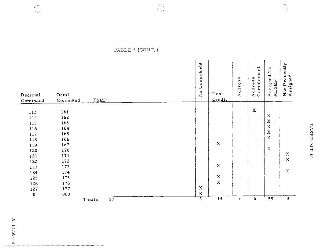
> I ,_. w
~ I
...... y::,..
Decimal Command
113 114 115 116 117 118 119 120 121 122 123 124 125 126 127
0
TABLE 3 (CONT.)
1:1)
'"0 s:: ro E E 0 u
Octal 0 z
Command PSEP
161 162 163 164 165 166 167 170 171 172 173 174 175 176 177 X
000 X -··
Totals 37 2
-l-' s:: (1)
oo E 1:1)
1:1) 1:1) Q)
il) 1!)..--l
1-< 1-< 0.. '"0 '"0 E
Test '"0 '"0 0
< <U Cmds.
X
X
X
X X
14 6 6
0 1:-i '"0
~p.. OJ)~ "(jj U)
rr. ...4 <<
X X X X X
X
55
>-~ -l-' s:: <I) 1:0'"0 <I) <I)
1-1 s:: P...~ -l-' 1:1)
0 1:1)
Z<
X X
X
8
M > Cfl M f-(j I
~ 1-3 I 0 .....


EASEP-MT-01
APPENDIX B
MEASUREMENT REQUIREMENTS DOCUMENT


EASEP-MT -01
INTRODUCTION
This document tabulates the measurements to be telemetered from the EASEP system. The included tables indicate the functions measured, the designation symbol, the assigned channel, accuracy, range, number of bits per sample, and sample rate provided via the PCM telemetry link.
Operational data is defined as that data required to indicate the readiness of the equipment to perform its intended function. In keeping with this definition, all of the data transmitted on analog housekeeping channels are designated as operational.
The A/D converter provided in the data subsystem is capable of encoding analog housekeeping and science signals to 8-bit accuracy. The encoded word occupies 10 bit positions to fill word 33 in the EASEP format. Each housekeeping signal is read out once in 90 frames of the PCM format. The analog multiplexer advances one position each frame. Digital data derived from the experiment has an output consistent with the frame format section of the Data Subsystem.
The following tables categorize the telemetered measurements:
Table 1 (a)
Table 1 {b)
Table 1 (c)
Table 2
- Channel Assignments for the Analog Multiplexer {ALSEP Word 33)
- Analog Housekeeping Channel Usage
- Summary of Analog Channel Usage
- Passive Seismic Experiment
B-1

B-2
EASEP-MT-01
-
1 2 3 4 5 6 7 8 X X X X NA X NA X
9 10 11 12 13 14 15 16 - X - X - X NA X
17 18 19 20 21 22 23 24 NA X NA X NA X NA X
25 26 27 28 29 30 31 32 - X - X - X NA X
33 34 35 36 37 38 39 40 H X ~ X , X NA X
41 42 43 44 45 46 47 48 - X - X - cv NA X
4'9 50 51 52 53 54 55 56 NA X NA X NA X NA NA
57 58 59 60 61 62 63 64 - X - X - X NA X
Legend
X
X
cv
H NA
- Control - Passive Seismic - Short Period - Passive Seismic - Long Period Seismic - Passive Seismic - Long Period Tidal and One
Temperature - Command Verification (upon command, otherwise
all zeros) - Housekeeping - Not Assigned (all 1 's are transmitted)
TOTAL
Each box contains one 1 O-bit word Total bits per frame - 10 x 64 = 640 bits
Figure l. EASEP Channel Assignment
Number of Words Per
Frame
3 29 12
2
1 1
] 6 64

b:J I lN
L r
PSEP WORD II
.L ~
CONTROL WORD· FORMAT
PSEP WORDfZ
~ ...... PSEP WORD f) --• '1
Bit 1 z 3 4 5 6 1 8 9 10 11 1z 13 14 15 16 11 18 19 zo z1 zz zs Z4 Z5 Z6 Z7 Z8 Z9 30 ll 1 1 0 0 0 1 0 0 1 0 0 0 0 1 1 1 0 1 1 0 11 Fl FZ F3 F4 F5 17 M
~ BARKER CODE COMPLEMENT OF BARKER CODE --+--FRAME COUNTER MODE (1, Z •••• 89, 0) BIT
PSEP Bite/ Samples/
~ Name Worda 1\an1e Sample Second
DA-1 Barker Code and Complement 1, Z, and NA zz 1. 67 bite 1 and Z of word 3
DA·Z Frame Count Bite 3 to 9 0-89 7 1.67 inclusive of word 3
DA·3 Bit Rate ID Bit 10 of word 3 1 1/54
~ Mode Bit Me anini
1 1 Normal data rate z 1 Slow.data rate
DA-4 PSEP ID Bit 10 of word 3 3 1/54
Frame Mode Bit
3 ! (MSB)} 4 Data processor 5 Serial number
DA-5*** Received Command Meaaa1e Bite 3 to 9 0-1Z7 7 •• inclusive of word 46 •
DA-6 Command MAP Bit 10 of word "0" no parity 1 •• 46 • "1" parity
DA-7 Filler Bite Bite 1 and Z of All zeros z •• word 46 • Bite 1 and Z of All zeros z 1. 67 word 33
**One word aamp1e·i• eent for each command received, other aamp1ee are all zeros. Maximum aamplin1 rate ia about once per second. * Command verification word ie 46
*** V erifiea reception and decodlft8 of commands by retranamiaaion of command meaaage.
Figure 2. Control and Command Verification Words
M ~ M '"d I
~ f-3 I 0 ......

EASEP-MT-01
TABLE 1 (a)
CHANNEL ASSIGNMENTS FOR ANALOG MULTIPLEXER (WORD 33)
Channel Number Flight System Channel Number Flight System
1. AE-3 39. AL-6 2. AE-1 40. BLANK 3. AE-2 41. AX-6 4. AT-3 42. AT-2 5. AE-4 43. AT-5 6. BLANK 44. BLANK 7. BLANK 45. BLANK 8. AE-5 46. AT-29 9. AB-1 47. AT-30
10. BLANK 48. AT-31 11. BLANK 49. AT-32 12. AB-4 50. AE .. 9 13. AE-6 51. AE-15 14. AB-5 52. BLANK 15. AT-10 53. AL-3 16. AT-21 54. AL-7 17. AT-22 55. BLANK 18. AT-23 56. AX-3 19. AT-24 57. BLANK 20. AE-7 58. AT-6 21. AE-13 59. AT-8 22. AE-18 60. AT-12 23. AL-l 61. AT-33 24. AL-5 62. AT-34 25. BLANK 63. AT-35 26. AX-5 64. AT-36 27. AT-1 65. AE-10 28. AT-4 66. AE-16 29. BLANK 67. BLANK 30. AX-2 68. AL-4 31. AT-25 69. AL-8 32. AT-26 70. BLANK 33. AT-27 71. AT-7 34. AT-28 72. AT-13 35. AE-8 73. BLANK 36. AE-14 74. BLANK 37. BLANK 75. BLANK 38. AL-2 76. AT-37
B-4

Channel Number
77. 78. 79. 80. 81. 82. 83. 84. 85. 86. 87. 88. 89. 90.
EASEP-MT-01
TABLE 1 (a) (CONT.)
Flight System
AT-38 AT-39 AE-11 AE-12 AE-17 BLANK AX-1 AX-4 BLANK BLANK AT-9 AT-11 BLANK BLANK
B-5

ttl I 0' TABLE 1 (b)
ANALOG HOUSEKEEPING CHANNEL USAGE
S:rmbol Location/Name Channel Ranse
Structural/Thermal Tem~eratures
AT-1 Solar Panel, East, Side 1 Z7 -300°F to +300°F AT-Z Solar Panel, West, Side 2 4Z II II
AT-3 Thermal Plate f 1 4 • 50°F to +Z00°F AT-4 II II IZ Z8 II II
AT-5 II " ##3 43 II II
AT-6 II " ##4 58 II II
AT-7 II " ##5 71 II II
AT-8 Left Side Structure #1 59 -300°F to +300°F AT-9 Ri1ht Side Structure #Z 87 II " AT-10 Bottom Structure #3 15 II II
AT-11 Back Structure #4 88 II .II
AT-lZ Inner Multilayer Insulation 60 -50 0F to +ZOOOF AT-13 Outer Multilayer Insulation 7Z -300°F to +300°F
Electronic Tem2eratures
AT-Zl Local OSC. Crystal A 16 • 50°F to +Z00°F AT-ZZ Local OSC. Crystal B 17 II II
AT-Z3 Transmitter A Crystal 18 II II
AT-Z4 Transmitter A Heat Sink 19 I II
AT-Z5 Transmitter B Crystal 31 II
AT-Z6 Transmitter B Heat Sink 3Z " AT-Z7 Analog Data Processor, Base 33 II
AT-Z8 Analog Data Processor, Internal 34 II
AT-Z9 Digital Data Processor, Base 46 " AT-30 Digital Data Processor, Internal 47 II
AT-31 Command Decoder, Base 48 II
AT·3Z Command Decoder, Internal 49 I II
AT-33 Command Demodulator VCO 61 II " AT-34 PDU, Base 6Z II " AT-35 PDU, Internal 63 II " AT-36 PCU, Power OSC #1 64 II " AT-37 PCU, Power OSC IZ 76 II " AT-38 PCU, Regulator #1 77 II It
AT-39 PCU, Regulator #Z 78 II It
Total of 3Z Central Station Temperatures
Sensor Bits/ Sample/ Accuraci Sam21e Sec.
+15°F 8 .0185 - II II " +10°F II "
II II " II II " II II " II II II
+15°F 8 .0185 II II " II II " II II "
+10°F II " '+15°F " II
M >
+10°F Ul
8 .0185 M II II II 1-cJ II II " I
II II II ~ II II II 1-3 II II II I
0 I II II ......
II
II
II
II
II
I II
II II
II II
" " " II II
II II II
II II "
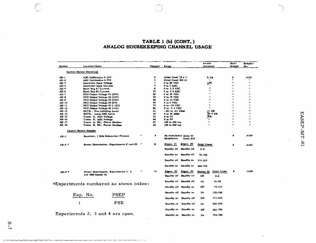
b:l I -..)
TABLE 1 (b) (CONT.) ANALOG HOUSEKEEPING CHANNEL USAGE
Senoor Blto/ Symbol Location/Name Ch_annel ~ .. na_~ _ _ ______ ~~~~~y _S&ft!i_ple
Central Station Electrical
AE-1 AOC Calibration 0. Z5V AE·Z AOC Calibration 4. 75V AE-3 Converter Input Voltase AE-4 Converter Input Current AE-S Shunt Rea f 1 Current AE-6 Shunt Res fZ Current AE-7 PCU Output Volta&e f1 (Z9VI AE-8 PCU Output Volta&e fZ (lSVI AE-9 PCU Output Voltase 13 (IZVI AE-10 PCU Output Voltaae 14 (SVI AE·Il PCU Output Voltaae IS (-lZVI AE-IZ PCU Output Voltaae 16 (-6VI AE-13 RCVR. , Pre-Llmitlna Level AE-14 RCVR, , Local OSC Level AE·lS Trano. A, AOC Voltaae 'AE-16 Trano. B, AOC Voltase AE-17 Trana. A, DC, Power Doubler AE-18 Tran•. B, DC • Power Doublu
Central Station Biotatic
AB·l
AB-4 *
AB-S *
Receiver, 1 KH& Subcarrier Preaent
Power Dlotrlbutlon, Experiment• fl and 12
Power Dbtribution, Experiment• 3, 4, and DSS Heater fZ
~~Experiments numbered as shown below:
Exp. No. PSEP
1 PSE
Experiments 2, 3 and 4 are open.
z 3 I 5 8
13 zo 3S 50 6S 79 80 Zl 36 51 66 81 Z2
9
12
14
Octal Couftt IS :1: I Octal CouBt 361 :1:1 0 to ZO VOC OtoSAOC 0 to 3, S AOC 0 to 3.5AOC 0 to 3S VDC 0 to 18 VDC 0 to IS VOC 0 to 6 VDC 0 to ·IS VOC 0 to -7.S VDC -101 to -61 DBM 0 to 10 DBM 0 to sv 0 to sv 100 to ZOO ma 100 to 200 ma
No modulation Octal 57 Modulation Octal275
E~r. fl E~r. fZ
Standby off Standby off
Standby on Standby off
Standby off Standby on
Standby on Standby on
E~r, U E~r. #4
Standby off Standby off
Standby off Standby off
Standby off Standby on
Standby off Standby on
Standby on Standby off
Standby on Standby off
Standby on Standby on
Standby on Standby on
0, S'Y.
!~."
+1 DB +o. S DB ,Is'Y. ..
E!:!!!.£ount
0-2
76-IZZ
171-21S
264-314
Heater #Z ~-t
Of£ 0-Z
On 31-SS
Off 73-117
On llZ-156
O£f 171-ZIS
On U6-ZSZ
O£f 262-loo
On 314-340
8
8
8
8
Sample/ Sec.
.0185
.0185
.0185
.Ol8S
M > Ul M 1-cJ I
~ 1-3 I
0 ......
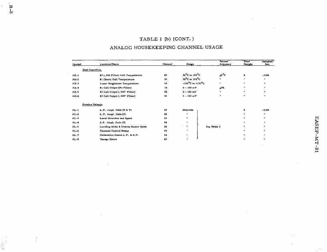
td I 00
TABLE 1 (b) (CONT. )
ANALOG HOUSEKEEPING CHANNEL USAGE
Senaor --Bite/ -------- Sainplel/ Symbol Location/Name Channel Rana:e Accuracy Sample Sec.
Duet Accretion
AX-I #3 (. OZO Filter) Cell Temperature
AX·Z *1 (Bare) Cell Temperature
AX-3 Lunar Brightne1a Temperature
AX-4 f I Cell Output {No Filter)
AX-5 fZ Cell Output (. 006" Filter)
AX-6 f3 Cell Output (. OZO" Filter)
Paaeive Sehmic
AL-l L.P. Amp!. Gain (X I< Y)
AL·Z L.P. Amp!. Galn-{Z)
AL-3 Level Direction and Speed
AL-4 S.P. Amp!. Gain (Z)
AL-5 Leveling Mode It Coarae Senaor Mode
AL-6 Thermal Control Statua
AL-7 Calibration Statue L. P. lr: s. P.
AL-8 Uncage Statue
83
30
56
~4
Z6
41
Z3
38
53
68
Z4
39
54
69
30°C to 150°C
30°C to 150°C
·150°C to +130°C
0 • ISO mV
0- ISO mV
0 • ISO mV
Dhcrete
.t8°C . 0185
.tl%
• 0185
"
See Table Z
M > Ul M '"d I
~ 1-3 I 0
'"""'

EASEP-MT-01
TABLE 1 (c)
SUMMARY OF ANALOG CHANNEL
Central Station
Data and Power Subsystems
Experiment On-Off Status
Structural/ Thermal
Experiments
Passive Seismic
Not As signed
TOTAL
TOTAL
38
2
13
53
8
29
90
B-9

td I I-' 0
TABLE Z
PASSIVE SEISMIC MEASUREMENT
Scientific M.eaau.remente:
A£SEP (Dynamic) Sene or Bita7 Symbo! Location/Meaau.rement Word Frame Ra!l~ ____ _ Ac~~~y_ Sample
DL-1 L. P. Seiamlc X 9,ZS,41,S7 Every I """'to 10 I' DL-Z L. P. Selamic Y II, Z7, 43, 59 " 1 mp to 10 p DL-3 L. P. Selomlc Z. 13, Z9, 45,61 .. Imp to lOp DL-4 Tidal: X 35 Even . 0 I to 10" (arc) DL-5 Tidal: y 37 Even .01 to IO"(arc) DL-6 Tidal: z 35 Odd 8 Jlll&l to 8 m1al DL-7 Senaor Unit Temp. 37 Odd 107-143°F DL-8 Short Period Sehmic: z Every Even Every I m1 to lOp
Word Except Z, 46,56
H<hl&ekeepiiUl Meaaurementa
8 channel• of Enpneerln1 Meaaurementa Included In ALSEP Word 33oall 0-5 VDC. Channel
AL-l L. P. Amp. Gain X, Y "-n-- Odb 0-0. 4V
AL·Z
AL-3
AL-4
AL-S
AL-6
AL-7
AL-8
L. P. Amp. Gain Z
Level Direction and Speed
S. P. Amp. Gain Z.
Leveling Mode and Coarae Senaor Mode
Thermal Control Statu.•
Calibration Statue LP lo SP
Uncage Statue ****
••• +0. OS°C reaolution. ••••Uncaae locked·o~.&t on all around teeta.
38
53
68
Z4
39
54
69
-lOdb 0.6-1.4 -ZOdb I. 6-Z. 4 -30db z. 6-4.0
Odb 0-0. 4V -IOdb 0.6-1.4 -ZOdb I. 6-Z. 4 -30db z. 6-4.0
+low 0-0.4V -low 0. 6-1.4 +hillh 1.6-Z.4 -hlp z.6-4.o
Odb 0-0. 4V -lOdb o. 6-1.4 -ZOdb 1. 6-Z. 4 -30db z. 6-4.0
Automatic, coarae level 'out Manual, coarae level out Automatic, coarae level in ManWLl, coarae level in
Automatic Mode ON AUtomatic Mode OFF Manual Mode ON Manual Mode OFF
Both ON LP-ON SP-OFF LP-OFF SP-ON Both OFF
Caged Arm Uncaae
0-0. 4V o. 6-1.4 1.6-Z.4
0-0. 4V o. 6-1.4 1. 6-Z. 4 z. 6-4.0
0-0. 4V o. 6-1.4 I. 6-Z.4 z. 6-4.0
0-0. 4V 0.6-1.4 I. 6-2.4 z. 6-4.0
5'Yo of reading 10
+l'ft of readinf** 11
S'Yo of reading
Octal Count 0 to zs 37 to 110 IZZ to 17Z ZOS to 314
0 to zs 37 to 110 IZZ to 172 zos to 314
0 to zs 37 to 110 IZZ to 17Z ZOS to 314
0 to zs 37 to 110 IZZ to 17Z ZOS to 314
0 to ZS 37 to 110 IZZ to 172 ZOS to 314
0 to Z5 37 to 110 lZZ to 17Z zos to 314
0 to Z5 37 to 110 IZZ to 172 ZOS to 314
0 to ZS 37 to 110 lZZ to 17Z
8
8
8
8
8
8
8
8
sample/ SarnPfe/ Sec Frame
6.ozs 4
" " " "
0;85 o.s o. as 0.5
" " " "
48.0 Z9
. 0185
.0185
. 0185 M > Ul M
.0185 1:J I
~ 1-3
.0185 I 0 ........
. 0185
.0185
.0185