Embed Size (px)
Citation preview

FlexPointTM Series UPS Technical Manual
FlexPoint 1208-F / 1232-D / 1250-D Series Indoor UPS Effective: September, 2015
Safety NotesReview the drawings and illustrations contained in this manual before proceeding. If there are any questions regarding the safe installation or operation of the system, contact Alpha Technologies or the nearest Alpha representative. Save this document for future reference.To reduce the risk of injury or death and to ensure the continued safe operation of this product, the following symbols have been placed throughout this manual. Where these symbols appear, use extra care and attention.
There may be multiple warnings associated with the call out. Example:
ELECTRICAL HAZARD WARNING provides electrical safety information to PREVENT INJURY OR DEATH to the technician or user.
WARNING! ELECTRICAL HAZARD
WARNING! FUMES HAZARD
FIRE HAZARD WARNING provides flammability safety information to PREVENT INJURY OR DEATH to the technician or user.
WARNING! FIRE HAZARD
WARNING! FIRE & ELECTRICAL HAZARD
ATTENTION:
The following sections contain important safety information that must be followed during the installation and maintenance of the equipment and batteries. Read all of the instructions before installing or operating the equipment. Save this manual for future reference.
ATTENTION provides specific regulatory/code requirements that may affect the placement of equipment and/or installation procedures.
NOTICE:NOTICE provides additional information to help complete a specific task or procedure.
CAUTION!
CAUTION provides safety information intended to PREVENT DAMAGE to material or equipment.
This WARNING provides safety information for both Electrical AND Fire Hazards
FUMES HAZARD WARNING provides fumes safety information to PREVENT INJURY OR DEATH to the technician or user.

3
FlexPoint 1208-F / 1232-D / 1250-D Series UPS
Technical Manual010-353-B9-001 Rev. A1Effective: September, 2015
© 2015 by Alpha Technologies, Inc.
DisclaimerImages contained in this manual are for illustrative purposes only. These images may not match every installation.Operator is cautioned to review the drawings and illustrations contained in this manual before proceeding. If there are questions regarding the safe operation of this powering system, please contact Alpha Technologies or the nearest Alpha representative.
Alpha shall not be held liable for any damage or injury involving its enclosures, power supplies, generators, batteries or other hardware if used or operated in any manner or subject to any condition not consistent with its intended purpose or is installed or operated in an unapproved manner or improperly maintained.
Contact InformationSales information and customer service in USA(7AM to 5PM, Pacific Time): 1 800 863 3930
Complete technical support in USA(7AM to 5PM, Pacific Time or 24/7 emergency support): 1 800 863 3364Sales information and technical support in Canada: 1 800 667 8743Website: www.alpha.com
010-353-B9-001 Rev. A1 (09/2015)4
Figures and TablesFig. 1-1, FlexPoint front view .............................................................................................................................. 7Fig. 1-2, FlexPoint right side view....................................................................................................................... 7Fig. 1-3, System block diagram .......................................................................................................................... 7Fig. 1-4, FlexPoint unit inventory ........................................................................................................................ 8Fig. 1-5, FlexPoint dimensions (in/[mm]) ............................................................................................................ 9Fig. 2-1, Removing the FlexPoint cover ........................................................................................................... 10Fig. 2-2, FlexPoint connections and components..............................................................................................11Fig. 2-3, 12Vdc output connector pin numbers..................................................................................................11Fig. 2-4, Removing the battery cover ............................................................................................................... 12Fig. 2-5, Connecting the battery wires .............................................................................................................. 12Fig. 2-6, FlexPoint battery securing options ..................................................................................................... 12Fig. 2-7, FlexPoint battery cover installation..................................................................................................... 12Fig. 3-1, Front panel displays (FP1208-F and FP1232-D / 1250-D)................................................................. 13
Table 1-1, Term definitions .................................................................................................................................. 6Table 1-2, FlexPoint battery options ................................................................................................................... 8 Table 2-1, 12Vdc output connector pin assignments .........................................................................................11Table 3-1, Audible alarms and visual indicators................................................................................................ 14Table 3-2, FlexPoint battery options ................................................................................................................. 14
Table of ContentsFlexPoint safety and compliance notes .............................................................................................................. 5Battery safety guidelines .................................................................................................................................... 51.0 Introduction ............................................................................................................................................ 6
1.1 List of terms .............................................................................................................................. 61.2 Theory of operation .................................................................................................................. 61.3 System features ........................................................................................................................ 71.4 Options ..................................................................................................................................... 81.5 FlexPoint 1208-F / 1232-D / 1250-D inventory ........................................................................ 81.6 FlexPoint dimensions ............................................................................................................... 9
2.0 Installation .......................................................................................................................................... 102.1 Installation and connection ..................................................................................................... 102.2 Installing the battery ............................................................................................................... 12
3.0 Operation ............................................................................................................................................ 133.1 Power on ................................................................................................................................ 133.2 Audible alarms and visual indicators ...................................................................................... 143.3 Battery .................................................................................................................................... 143.4 Operational modes ................................................................................................................. 15
3.4.1 Normal mode ............................................................................................................ 153.4.2 Back-Up mode ........................................................................................................... 153.4.3 Charging mode .......................................................................................................... 153.4.4 Mute mode ................................................................................................................. 15
4.0 Specifications ...................................................................................................................................... 164.1 Flexpoint 1208-F specifications .............................................................................................. 164.2 Flexpoint 1232-D specifications .............................................................................................. 174.3 Flexpoint 1250-D specifications .............................................................................................. 18
5010-353-B9-001 Rev. A1 (09/2015)
FlexPoint safety and compliance notesReview the drawings and illustrations contained in this manual before proceeding. If there are any questions regarding the safe installation or operation of the system, contact Alpha Technologies or the nearest Alpha representative. Save this document for future reference.To reduce the risk of injury or death, and to ensure the continued safe operation of this product, the following symbols have been placed throughout this manual. Where these symbols appear, use extra care and attention.
NOTICE:
Follow all safety information within this manual. If there are any questions regarding the proper installation of the product, contact Alpha Technologies, 1 800 863 3364.
CAUTION!
• Always replace batteries with those of an identical type and rating. Never install untested batteries.• Spent or damaged batteries are environmentally unsafe. Always recycle used batteries. Refer to local codes for proper disposal of batteries.
ATTENTION: Federal Communications Commission (FCC) CLASS B Statement
CAUTION!
This equipment has been tested and found to comply with the limits for a Class B digital device, pursuant to Part 15 of the FCC rules. These limits are designed to provide reasonable protection against harmful interference in a residential installation. This equipment generates, uses and can radiate radio frequency energy and, if not installed and used in accordance with the instructions, may cause harmful interference to radio communications. However, there is no guarantee that interference will not occur in a particular installation. If this equipment does cause harmful interference to radio or television reception, which can be determined by turning the equipment off and on, the user is encouraged to try to correct the interference by one or more of the following measures:
• Reorient or relocate the receiving antenna.• Increase the separation between the equipment and the receiver.• Connect the equipment into an outlet on a circuit different from that to which the receiver is
connected.• Consult the dealer or an experienced radio/TV technician for help.
For further information Visit: https://www.fcc.gov/guides/interference-defining-sourceChanges and modifications not expressly approved by the manufacturer or registrant of this equipment can void your authority to operate this equipment under FCC rules.
Battery safety guidelines• Follow all battery manufacturer’s storage and maintenance instructions.
Confirm all FlexPoint unit inventory items are present before beginning the installation process, see Section 1.5, FlexPoint 1208-F / 1232-D / 1250-D Inventory.
010-353-B9-001 Rev. A1 (09/2015)6
NOTICE:
Table 1-1, Term definitions
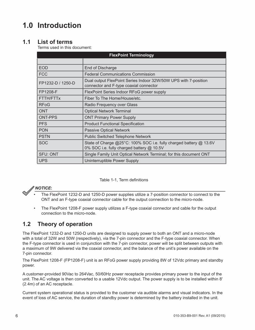
• The FlexPoint 1232-D and 1250-D power supplies utilize a 7-position connector to connect to the ONT and an F-type coaxial connector cable for the output connection to the micro-node.
• The FlexPoint 1208-F power supply utilizes a F-type coaxial connector and cable for the output connection to the micro-node.
1.2 Theory of operationThe FlexPoint 1232-D and 1250-D units are designed to supply power to both an ONT and a micro-node with a total of 32W and 50W (respectively), via the 7-pin connector and the F-type coaxial connector. When the F-type connector is used in conjunction with the 7-pin connector, power will be split between outputs with a maximum of 9W delivered via the coaxial connector, and the balance of the unit’s power available on the 7-pin connector.The FlexPoint 1208-F (FP1208-F) unit is an RFoG power supply providing 8W of 12Vdc primary and standby power.
A customer-provided 90Vac to 264Vac, 50/60Hz power receptacle provides primary power to the input of the unit. The AC voltage is then converted to a usable 12Vdc output. The power supply is to be installed within 8' (2.4m) of an AC receptacle.
Current system operational status is provided to the customer via audible alarms and visual indicators. In the event of loss of AC service, the duration of standby power is determined by the battery installed in the unit.
1.0 Introduction
1.1 List of terms Terms used in this document:
FlexPoint Terminology
EOD End of DischargeFCC Federal Communications Commission
FP1232-D / 1250-D Dual output FlexPoint Series Indoor 32W/50W UPS with 7-position connector and F-type coaxial connector
FP1208-F FlexPoint Series Indoor RFoG power supplyFTTH/FTTx Fiber To The Home/House/etc.RFoG Radio Frequency over GlassONT Optical Network TerminalONT-PPS ONT Primary Power SupplyPFS Product Functional SpecificationPON Passive Optical NetworkPSTN Public Switched Telephone NetworkSOC State of Charge @25°C: 100% SOC i.e. fully charged battery @ 13.6V
0% SOC i.e. fully charged battery @ 10.5VSFU: ONT Single Family Unit Optical Network Terminal; for this document ONTUPS Uninterruptible Power Supply
7010-353-B9-001 Rev. A1 (09/2015)
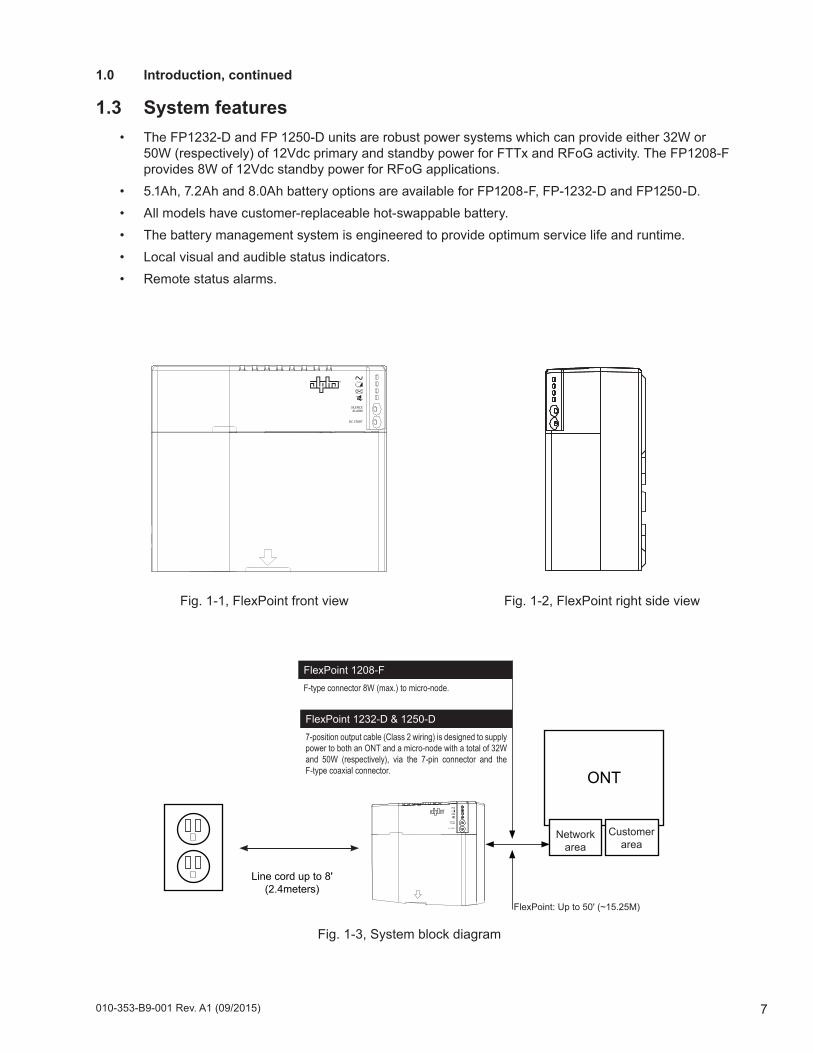
ONT
FlexPoint 1232-D & 1250-D7-position output cable (Class 2 wiring) is designed to supply power to both an ONT and a micro-node with a total of 32W and 50W (respectively), via the 7-pin connector and the F-type coaxial connector.
FlexPoint 1208-FF-type connector 8W (max.) to micro-node.
1.0 Introduction, continued
1.3 System features• The FP1232-D and FP 1250-D units are robust power systems which can provide either 32W or
50W (respectively) of 12Vdc primary and standby power for FTTx and RFoG activity. The FP1208-F provides 8W of 12Vdc standby power for RFoG applications.
• 5.1Ah, 7.2Ah and 8.0Ah battery options are available for FP1208-F, FP-1232-D and FP1250-D.• All models have customer-replaceable hot-swappable battery.• The battery management system is engineered to provide optimum service life and runtime.• Local visual and audible status indicators.• Remote status alarms.
FlexPoint: Up to 50' (~15.25M)
Networkarea
Customerarea
Line cord up to 8'(2.4meters)
Fig. 1-1, FlexPoint front view Fig. 1-2, FlexPoint right side view
Fig. 1-3, System block diagram
010-353-B9-001 Rev. A1 (09/2015)8
Battery OptionsAX-STDBAT-5 Battery 5.1 Ah AGM, 1-year warranty
AX-STDBAT-7 Battery 7.2 Ah AGM, 1-year warranty
AX-LONGBAT-7 Battery 7.2 Ah AGM, 3-year warranty
AX-LONGBAT-8 Battery 8 Ah AGM, 3-year warranty
FTTH-CBL ONT hook-up cable, 2x16 AWG and 5x24 AWG, CMX UL listed Optional battery strap Alpha p/n 660-112-10
FlexPoint™ 1215, 1232, 1250 Quick Start GuideFTTx UPS System for ONTs
Fig. 1, System Block Diagram
Review the drawings and illustrations contained in this guide before proceeding. For additional details on installation and operation, visit www.alpha.com and download a copy of the FlexPointTM 1215, 1232, 1250 Series Technical Manual (p/n 010-353-B0).
The FlexPoint 1215, 1232 and 1250 units are optical network terminal (ONT) providing of 12Vdc primary and standby power. A customer-provided 90Vac to 264Vac, 50/60Hz power receptacle provides primary power to the input of the unit. The AC voltage is then converted to a usable 12Vdc output. Backup power and batteries are long life, easy to replace, purchase, and install. Power status is provided to the customer via audible alarms and visual indicators. Upon loss of AC service, the duration of standby power is determined by the battery installed in the unit.
1. Unpack and inspect the FlexPoint power supply.
2. Install the unit within 8' (2.4 m) to an AC outlet with 6" (15.2 cm) of space above and below, 2–4" (5–10 cm) in front and 2" (5 cm) of space on either side to provide adequate thermal ventilation.
3. the cover bottom away from the unit and down.
4. Determine the necessary cable length to provide appropriate service loops between the unit, the ONT, and the AC receptacle. Plug the line cord into the receptacle in the unit. Secure line cord at one of the cable tie holes with one included cable tie. Do not plug the unit into an AC receptacle until the last step of the installation procedure.
5. Determine output cable length. Connect cable into 7 position connector. Attach connector to header located on back of unit. Route cable down provided channel. Secure the cable tie and the optional battery strap through the unit.
6. Mount to the wall with #12 fasteners or equivalent, using the keyholes for easy mounting. For applications with higher seismic requirements, use the round hole in the back of the unit for direct fastening to a stud or other structural feature.
Installing and Connecting the FlexPoint Unit
• The unit is designed for use in an indoor environment protected from rain and snow. Its operating temperature range is -10°C to 45°C / 14°F to 113°F (ambient).
• The power supply cord is used as the main disconnect device. Verify the AC receptacle is located/installed near the equipment and is easily accessible.
CAUTION!
ONT
Line Cord Up to 8',(2.4 meters)
Network Area
CustomerArea
FlexPoint 1215, 1232, 12507-position output cable (Class 2 wiring)
FlexPoint: Up to 50' (~15.25 meters)
During normal operation, press the Silence Alarm button to get the recommended battery capacity: 5Ah – 1 chirp; 7Ah – 3 chirps; 8Ah – 4 chirps.
NOTICE:
PRELIMINARY
1
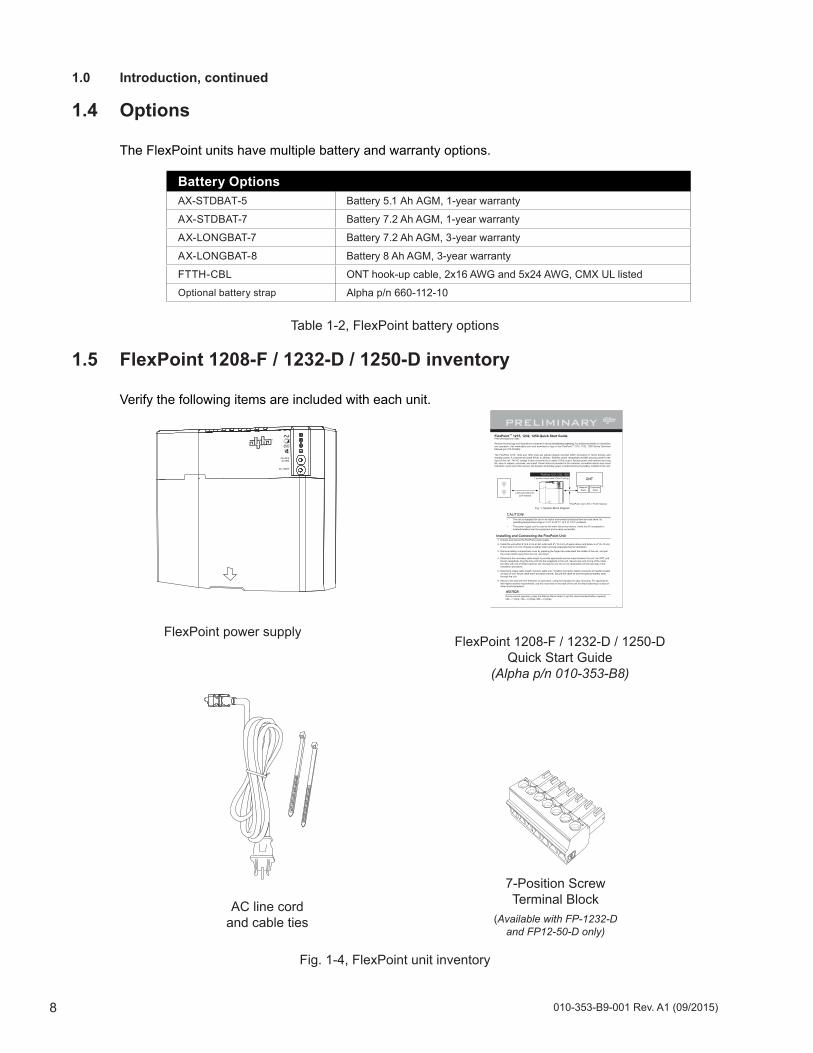
FlexPoint power supply
7-Position Screw Terminal Block
(Available with FP-1232-D and FP12-50-D only)
AC line cord and cable ties
1.0 Introduction, continued
1.4 Options
The FlexPoint units have multiple battery and warranty options.
FlexPoint 1208-F / 1232-D / 1250-D Quick Start Guide
(Alpha p/n 010-353-B8)
1.5 FlexPoint 1208-F / 1232-D / 1250-D inventory
Verify the following items are included with each unit.
Fig. 1-4, FlexPoint unit inventory
Table 1-2, FlexPoint battery options
9010-353-B9-001 Rev. A1 (09/2015)
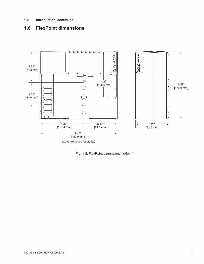
7.48"[190.0 mm]
3.19"[81.0 mm]
4.23"[107.4 mm]
6.57"[166.9 mm]
2.52"[64.0 mm]
2.83"[71.8 mm]
4.29"[108.9 mm]
3.23"[82.0 mm]
(Cover removed for clarity)
1.0 Introduction, continued
1.6 FlexPoint dimensions
Fig. 1-5, FlexPoint dimensions (in/[mm])
010-353-B9-001 Rev. A1 (09/2015)10
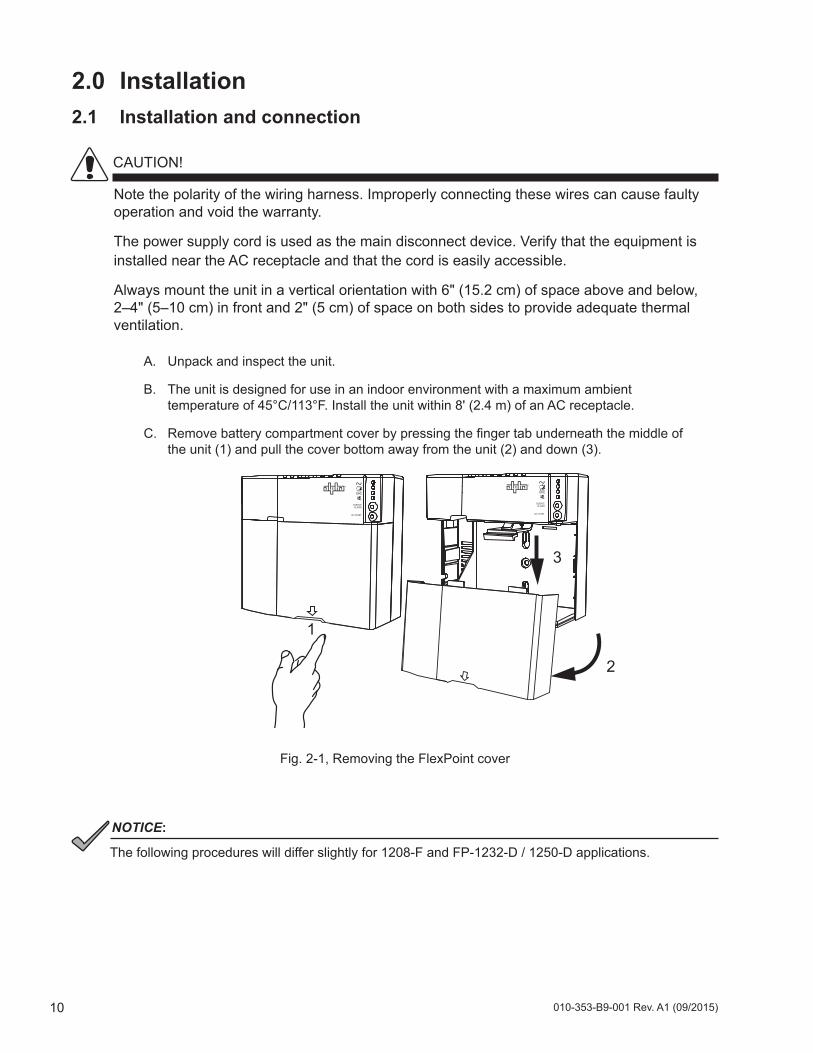
Fig. 2-1, Removing the FlexPoint cover
The following procedures will differ slightly for 1208-F and FP-1232-D / 1250-D applications.
NOTICE:
Note the polarity of the wiring harness. Improperly connecting these wires can cause faulty operation and void the warranty.
The power supply cord is used as the main disconnect device. Verify that the equipment is installed near the AC receptacle and that the cord is easily accessible.
Always mount the unit in a vertical orientation with 6" (15.2 cm) of space above and below, 2–4" (5–10 cm) in front and 2" (5 cm) of space on both sides to provide adequate thermal ventilation.
2.0 Installation 2.1 Installation and connection
2
3
1
A. Unpack and inspect the unit.
B. The unit is designed for use in an indoor environment with a maximum ambient temperature of 45°C/113°F. Install the unit within 8' (2.4 m) of an AC receptacle.
C. Remove battery compartment cover by pressing the finger tab underneath the middle of the unit (1) and pull the cover bottom away from the unit (2) and down (3).
CAUTION!
11010-353-B9-001 Rev. A1 (09/2015)
2.0 Installation, continued
2.1 Installation and connection, continued
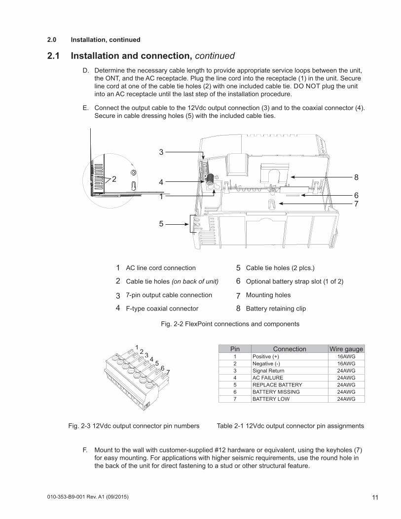
Pin Connection Wire gauge1 Positive (+) 16AWG2 Negative (-) 16AWG3 Signal Return 24AWG4 AC FAILURE 24AWG5 REPLACE BATTERY 24AWG6 BATTERY MISSING 24AWG7 BATTERY LOW 24AWG
7654321
1
8
76
D. Determine the necessary cable length to provide appropriate service loops between the unit, the ONT, and the AC receptacle. Plug the line cord into the receptacle (1) in the unit. Secure line cord at one of the cable tie holes (2) with one included cable tie. DO NOT plug the unit into an AC receptacle until the last step of the installation procedure.
E. Connect the output cable to the 12Vdc output connection (3) and to the coaxial connector (4). Secure in cable dressing holes (5) with the included cable ties.
12
4
3
34
2
Cable tie holes (2 plcs.)
Optional battery strap slot (1 of 2)
Mounting holes
Battery retaining clip
56
7
AC line cord connection
Cable tie holes (on back of unit)
7-pin output cable connection
F-type coaxial connector
Fig. 2-2 FlexPoint connections and components
5
8
F. Mount to the wall with customer-supplied #12 hardware or equivalent, using the keyholes (7) for easy mounting. For applications with higher seismic requirements, use the round hole in the back of the unit for direct fastening to a stud or other structural feature.
Fig. 2-3 12Vdc output connector pin numbers Table 2-1 12Vdc output connector pin assignments
010-353-B9-001 Rev. A1 (09/2015)12
2.0 Installation, continued
2.2 Installing the battery
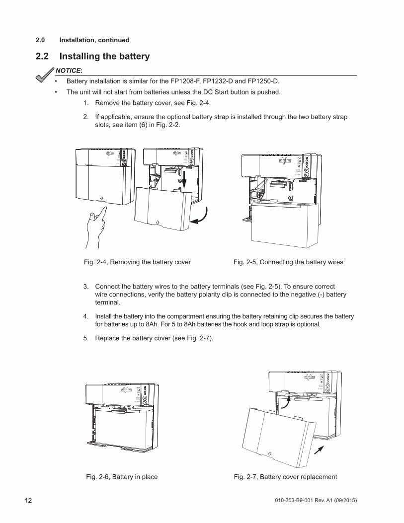
1. Remove the battery cover, see Fig. 2-4.
2. If applicable, ensure the optional battery strap is installed through the two battery strap slots, see item (6) in Fig. 2-2.
Fig. 2-4, Removing the battery cover Fig. 2-5, Connecting the battery wires
Fig. 2-7, Battery cover replacementFig. 2-6, Battery in place
3. Connect the battery wires to the battery terminals (see Fig. 2-5). To ensure correct wire connections, verify the battery polarity clip is connected to the negative (-) battery terminal.
4. Install the battery into the compartment ensuring the battery retaining clip secures the battery for batteries up to 8Ah. For 5 to 8Ah batteries the hook and loop strap is optional.
5. Replace the battery cover (see Fig. 2-7).
• Battery installation is similar for the FP1208-F, FP1232-D and FP1250-D.• The unit will not start from batteries unless the DC Start button is pushed.
NOTICE:
13010-353-B9-001 Rev. A1 (09/2015)
Fig. 3-1, Front panel display (FP1208-F and FP 1232-D / 1250-D)
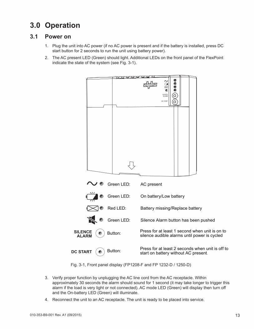
3.0 Operation3.1 Power on
1. Plug the unit into AC power (if no AC power is present and if the battery is installed, press DC start button for 2 seconds to run the unit using battery power).
2. The AC present LED (Green) should light. Additional LEDs on the front panel of the FlexPoint indicate the state of the system (see Fig. 3-1).
3. Verify proper function by unplugging the AC line cord from the AC receptacle. Within approximately 30 seconds the alarm should sound for 1 second (it may take longer to trigger this alarm if the load is very light or not connected). AC mode LED (Green) will display then turn off and the On-battery LED (Green) will illuminate.
4. Reconnect the unit to an AC receptacle. The unit is ready to be placed into service.
Green LED: AC present
Green LED: On battery/Low battery
Red LED: Battery missing/Replace battery
Green LED: Silence Alarm button has been pushed
SILENCE ALARM
DC START
Button: Press for at least 1 second when unit is on to silence audible alarms until power is cycled
Button: Press for at least 2 seconds when unit is off to start on battery without AC present.
010-353-B9-001 Rev. A1 (09/2015)14
3.0 Operation, continued
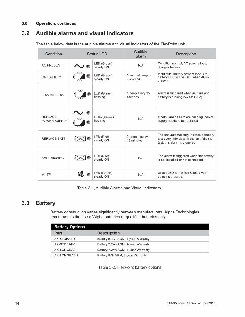
3.2 Audible alarms and visual indicators
The table below details the audible alarms and visual indicators of the FlexPoint unit.
Condition Status LED Audible alarm Description
AC PRESENT LED (Green) steady ON N/A Condition normal; AC powers load,
charges battery.
ON BATTERY LED (Green) steady ON
1 second beep on loss of AC
Input fails; battery powers load. On battery LED will be OFF when AC is present.
LOW BATTERY LED (Green) flashing
1 beep every 15 seconds
Alarm is triggered when AC fails and battery is running low (<11.7 V).
REPLACE POWER SUPPLY
LEDs (Green) flashing N/A If both Green LEDs are flashing, power
supply needs to be replaced
REPLACE BATT LED (Red) steady ON
2 beeps, every 15 minutes
The unit automatically initiates a battery test every 180 days. If the unit fails the test, this alarm is triggered.
BATT MISSING LED (Red) steady ON N/A The alarm is triggered when the battery
is not installed or not connected.
MUTE LED (Green) steady ON N/A Green LED is lit when Silence Alarm
button is pressed.
3.3 BatteryBattery construction varies significantly between manufacturers. Alpha Technologies recommends the use of Alpha batteries or qualified batteries only.
Battery OptionsPart DescriptionAX-STDBAT-5 Battery 5.1Ah AGM, 1-year Warranty
AX-STDBAT-7 Battery 7.2Ah AGM, 1-year Warranty
AX-LONGBAT-7 Battery 7.2Ah AGM, 3-year Warranty
AX-LONGBAT-8 Battery 8Ah AGM, 3-year Warranty
Table 3-1, Audible Alarms and Visual Indicators
Table 3-2, FlexPoint battery options
15010-353-B9-001 Rev. A1 (09/2015)
3.0 Operation, continued
3.4 Operational modes3.4.1 Normal mode This mode is defined as a state where the load is being supplied from AC input, and the battery is floating, charging or in the process of being tested.When the unit is initially powered up, or whenever the input supply has been restored after an outage, the unit operates in charge mode. Once the battery voltage has reached the full charge voltage, the unit switches to float mode. If the input voltage is less than the minimum AC input, the system switches to operating in back-up mode.After approximately 180 days of operation, the battery is automatically tested to determine whether it has adequate capacity. It is tested when the following conditions are met:
The battery is operating in float mode for 24 hours; and,The battery is fully charged in the temperature between 5°C to 35°C / 40°F to 95°F for 24 hours.The Replace battery alarm is not active (triggered if the power module charger is in accept mode for 1 hour with the battery below 10.5V).The Power module over voltage is not active (where the power module output is higher than the target by 500mV for 75 seconds).
If the above conditions are not met when the test becomes due, the test is postponed until those conditions are met. If the AC input is lost, or the unit is overloaded during the battery test, it will be aborted and post-poned until conditions are valid.Once a battery test has been successfully executed, another test will be automatically scheduled to occur in 180 days, without regard to the test results.
3.4.2 Back-Up mode
The load is being supplied from the battery while the battery voltage is greater than 10.5Vdc. When the bat-tery falls below this value, it is disconnected.
3.4.3 Charging mode
This maintains the battery at 100% capacity. After an AC outage, when AC is present, the charger continues charging until one of the following occurs:
• Battery has reached 100% capacity.• Charging is reduced to float charge level. Normal BULK charge current is approximately 800mA. • When in ACCEPT MODE the current falls below 150mA, the mode changes to FLOAT. In the event
the current does not reduce, the software triggers the mode change after 48 hours in ACCEPT• Another power failure occurs requiring battery support.
No special action is required to restore normal operation once primary power is restored.
3.4.4 Mute mode
Pressing the Silence Alarm button puts the unit into Mute mode. In this mode the green Mute LED will illuminate and remain illuminated until Silence Alarm is pressed again. Audible Alarm indicators will be silenced, but all other alarm functionality remains the same, see Table 3-1.
010-353-B9-001 Rev. A1 (09/2015)16
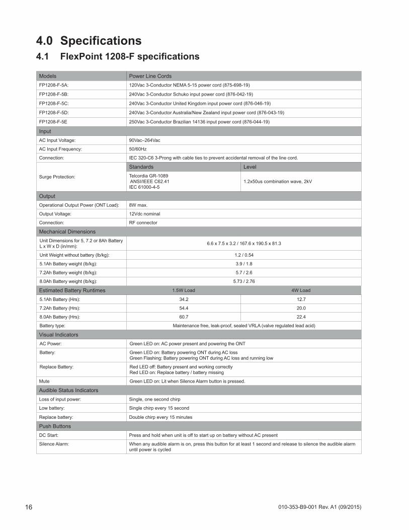
4.0 Specifications
Models Power Line CordsFP1208-F-5A: 120Vac 3-Conductor NEMA 5-15 power cord (875-698-19)
FP1208-F-5B: 240Vac 3-Conductor Schuko input power cord (876-042-19)
FP1208-F-5C: 240Vac 3-Conductor United Kingdom input power cord (876-046-19)
FP1208-F-5D: 240Vac 3-Conductor Australia/New Zealand input power cord (876-043-19)
FP1208-F-5E 250Vac 3-Conductor Brazilian 14136 input power cord (876-044-19)
InputAC Input Voltage: 90Vac–264Vac
AC Input Frequency: 50/60Hz
Connection: IEC 320-C6 3-Prong with cable ties to prevent accidental removal of the line cord.
Surge Protection:
Standards LevelTelcordia GR-1089 ANSI/IEEE C62.41 IEC 61000-4-5
1.2x50us combination wave, 2kV
OutputOperational Output Power (ONT Load): 8W max.
Output Voltage: 12Vdc nominal
Connection: RF connector
Mechanical DimensionsUnit Dimensions for 5, 7.2 or 8Ah Battery L x W x D (in/mm): 6.6 x 7.5 x 3.2 / 167.6 x 190.5 x 81.3
Unit Weight without battery (lb/kg): 1.2 / 0.54
5.1Ah Battery weight (lb/kg): 3.9 / 1.8
7.2Ah Battery weight (lb/kg): 5.7 / 2.6
8.0Ah Battery weight (lb/kg): 5.73 / 2.76
Estimated Battery Runtimes 1.5W Load 4W Load
5.1Ah Battery (Hrs): 34.2 12.7
7.2Ah Battery (Hrs): 54.4 20.0
8.0Ah Battery (Hrs): 60.7 22.4
Battery type: Maintenance free, leak-proof, sealed VRLA (valve regulated lead acid)
Visual IndicatorsAC Power: Green LED on: AC power present and powering the ONT
Battery: Green LED on: Battery powering ONT during AC lossGreen Flashing: Battery powering ONT during AC loss and running low
Replace Battery: Red LED off: Battery present and working correctlyRed LED on: Replace battery / battery missing
Mute Green LED on: Lit when Silence Alarm button is pressed.
Audible Status IndicatorsLoss of input power: Single, one second chirp
Low battery: Single chirp every 15 second
Replace battery: Double chirp every 15 minutes
Push ButtonsDC Start: Press and hold when unit is off to start up on battery without AC present
Silence Alarm: When any audible alarm is on, press this button for at least 1 second and release to silence the audible alarm until power is cycled
4.1 FlexPoint1208-Fspecifications
17010-353-B9-001 Rev. A1 (09/2015)
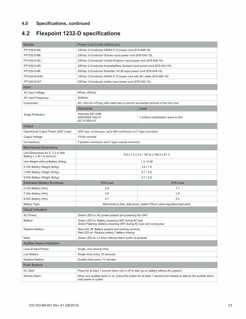
Models Power Line Cords (Alpha p/n)FP1232-D-8A: 120Vac 3-Conductor NEMA 5-15 power cord (875-698-19)
FP1232-D-8B: 230Vac 3-Conductor Schuko input power cord (876-042-19)
FP1232-D-8C: 230Vac 3-Conductor United Kingdom input power cord (876-046-19)
FP1232-D-8D: 240Vac 3-Conductor Australia/New Zealand input power cord (876-043-19)
FP1232-D-8E: 250Vac 3-Conductor Brazilian 14136 input power cord (876-044-19)
FP1232-D-8-6C: 120Vac 3-Conductor NEMA 5-15 power cord with BC cable (875-698-19)
FP1232-D-8-F: 230Vac 3-Conductor Indian input power cord (876-045-19)
InputAC Input Voltage: 90Vac–264Vac
AC Input Frequency: 50/60Hz
Connection: IEC 320-C6 3-Prong with cable ties to prevent accidental removal of the line cord.
Surge Protection:
Standards LevelTelcordia GR-1089ANSI/IEEE C62.41 IEC 61000-4-5
1.2x50us combination wave at 2kV
OutputOperational Output Power (ONT Load): 32W max. continuous, up to 9W continuous on F-type connector
Output Voltage: 12Vdc nominal
Connections: 7-position connector and F-type coaxial connector
Mechanical DimensionsUnit Dimensions for 5, 7.2 or 8Ah Battery L x W x D (in/mm): 6.6 x 7.5 x 3.2 / 167.6 x 190.5 x 81.3
Unit Weight without Battery (lb/kg): 1.3 / 0.59
5.1Ah Battery Weight (lb/kg): 3.9 / 1.8
7.2Ah Battery Weight (lb/kg): 5.7 / 2.6
8.0Ah Battery Weight (lb/kg): 5.7 / 2.6
Estimated Battery Runtimes 16W Load 32W Load
5.1Ah Battery (Hrs): 2.5 1.1
7.2Ah Battery (Hrs): 3.9 1.6
8.0Ah Battery (Hrs): 4.7 2.0
Battery Type: Maintenance free, leak-proof, sealed VRLA (valve regulated lead acid)
Visual Indicators
AC Power: Green LED on: AC power present and powering the ONT
Battery: Green LED on: Battery powering ONT during AC lossGreen Flashing: Battery powering ONT during AC loss and running low
Replace Battery: Red LED off: Battery present and working correctlyRed LED on: Replace battery / battery missing
Mute Green LED on: Lit when Silence Alarm button is pressed.
Audible Status Indicators
Loss of Input Power: Single, one second chirp
Low Battery: Single chirp every 15 seconds
Replace Battery: Double chirp every 15 minutes
Push Buttons
DC Start: Press for at least 1 second when unit is off to start up on battery without AC present
Silence Alarm: When any audible alarm is on, press this button for at least 1 second and release to silence the audible alarm until power is cycled
4.0 Specifications,continued
4.2 Flexpoint1232-Dspecifications
010-353-B9-001 Rev. A1 (09/2015)18
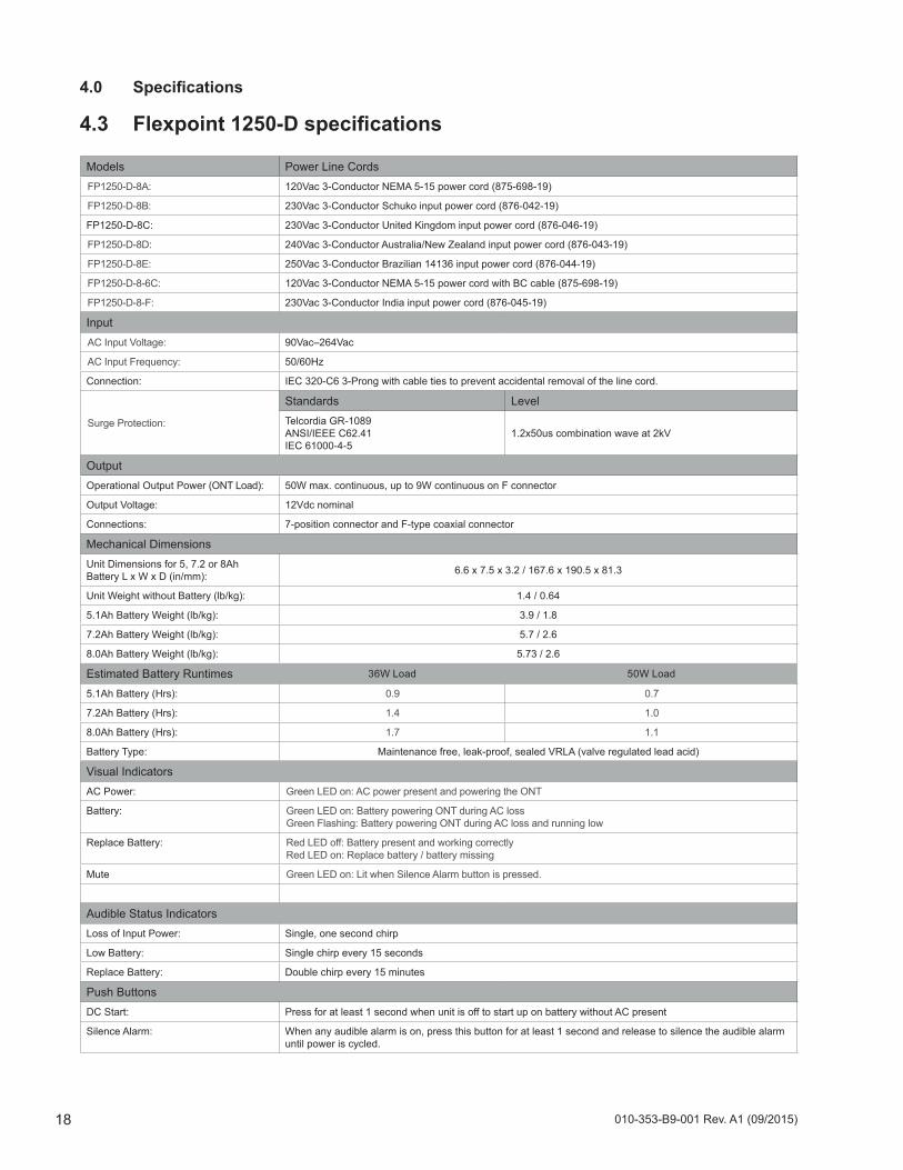
Models Power Line CordsFP1250-D-8A: 120Vac 3-Conductor NEMA 5-15 power cord (875-698-19)
FP1250-D-8B: 230Vac 3-Conductor Schuko input power cord (876-042-19)
FP1250-D-8C: 230Vac 3-Conductor United Kingdom input power cord (876-046-19)
FP1250-D-8D: 240Vac 3-Conductor Australia/New Zealand input power cord (876-043-19)
FP1250-D-8E: 250Vac 3-Conductor Brazilian 14136 input power cord (876-044-19)
FP1250-D-8-6C: 120Vac 3-Conductor NEMA 5-15 power cord with BC cable (875-698-19)
FP1250-D-8-F: 230Vac 3-Conductor India input power cord (876-045-19)
InputAC Input Voltage: 90Vac–264Vac
AC Input Frequency: 50/60Hz
Connection: IEC 320-C6 3-Prong with cable ties to prevent accidental removal of the line cord.
Surge Protection:
Standards LevelTelcordia GR-1089ANSI/IEEE C62.41 IEC 61000-4-5
1.2x50us combination wave at 2kV
OutputOperational Output Power (ONT Load): 50W max. continuous, up to 9W continuous on F connector
Output Voltage: 12Vdc nominal
Connections: 7-position connector and F-type coaxial connector
Mechanical DimensionsUnit Dimensions for 5, 7.2 or 8Ah Battery L x W x D (in/mm): 6.6 x 7.5 x 3.2 / 167.6 x 190.5 x 81.3
Unit Weight without Battery (lb/kg): 1.4 / 0.64
5.1Ah Battery Weight (lb/kg): 3.9 / 1.8
7.2Ah Battery Weight (lb/kg): 5.7 / 2.6
8.0Ah Battery Weight (lb/kg): 5.73 / 2.6
Estimated Battery Runtimes 36W Load 50W Load
5.1Ah Battery (Hrs): 0.9 0.7
7.2Ah Battery (Hrs): 1.4 1.0
8.0Ah Battery (Hrs): 1.7 1.1
Battery Type: Maintenance free, leak-proof, sealed VRLA (valve regulated lead acid)
Visual IndicatorsAC Power: Green LED on: AC power present and powering the ONT
Battery: Green LED on: Battery powering ONT during AC lossGreen Flashing: Battery powering ONT during AC loss and running low
Replace Battery: Red LED off: Battery present and working correctlyRed LED on: Replace battery / battery missing
Mute Green LED on: Lit when Silence Alarm button is pressed.
Audible Status IndicatorsLoss of Input Power: Single, one second chirp
Low Battery: Single chirp every 15 seconds
Replace Battery: Double chirp every 15 minutes
Push ButtonsDC Start: Press for at least 1 second when unit is off to start up on battery without AC present
Silence Alarm: When any audible alarm is on, press this button for at least 1 second and release to silence the audible alarm until power is cycled.
4.0 Specifications
4.3 Flexpoint1250-Dspecifications


Visit us at www.alpha.com
Alpha Technologies Inc.3767 Alpha WayBellingham, WA 98226 United StatesTel: +1 360 647 2360Fax: +1 360 671 4936
Alpha Technologies Ltd.7700 Riverfront GateBurnaby, BC V5J 5M4 CanadaTel: +1 604 436 5900Fax: +1 604 436 1233Toll Free: +1 800 667 8743
Alpha Industrial Power Inc.1075 Satellite Blvd NW, Suite 400Suwanee, GA 30024 United StatesTel: +1 678 475 3995Fax: +1 678 584 9259
Alpha Energy1628 W Williams DrivePhoenix, AZ 85027 United StatesTel: +1 360 647 2360Fax: +1 360 671 4936
Alpha Technologies GmbHHansastrasse 8D-91126Schwabach, GermanyTel: +49 9122 79889 0Fax: +49 9122 79889 21
Technologies Argus First de MexicoAnatole France Num. 17 Colonia Polanco11560, México D.F. Tel: +52 55 5280 6990
Alpha Technologies Europe Ltd.Twyford House ThorleyBishop’s StortfordHertfordshire, CM22 7PA United KingdomTel: +44 1279 501110Fax: +44 1279 659870
Alphatec Ltd.339 St. Andrews St. Suite 101 Andrea ChambersP.O. Box 564683307 Limassol, CyprusTel: +357 25 375 675Fax: +357 25 359 595
Alpha TEK oooKhokhlovskiy Pereulok 16Stroenie 1, Office 403Moscow, 109028 RussiaTel: +7 495 916 1854Fax: +7 495 916 1349
Alpha TechnologiesSuite 1903, Tower 1, 33 Canton Road, Kowloon Hong Kong, ChinaPhone: +852 2736 8663Fax: +852 2199 7988
Alpha Innovations BrasilAvenida Ibirapuera, 2120 – Cj 76Moema - 04028-001Santos SP, BrazilTel: +55 11 2476 0150Fax: +55 11 2476 0150
Alphatec BalticS. Konarskio Street 49-201Vilnius, LT-03123 LithuaniaTel: +370 5 210 5291Fax: +370 5 210 5292
Due to continuing product development, Alpha Technologies reserves the right to change specifications without notice. Copyright © 2015 Alpha Technologies. All Rights Reserved. Alpha® is a registered trademark of Alpha Technologies. 010-353-B9-001 Rev. A1 (09/2015)