Embed Size (px)
Citation preview
FIXED PROSTHODONTICS OPERATIVE DENTISTRY DAVID E. BEAUDREAU, SAMUEL E. GUYER, WILLIAM LEFKOWITZ, Section editors
A method of transferring mandibular-movement data to computer storage Richard B. McCoy, D.D.S.,M.S.,·*Edwin F. Shryock, D.D.S.,M.S.,**and Harry C. Lundeen, D.D.S.*** Bethesda, Md., and Gainesville, FL Accurate reproduction of mandibular movements is of prime importance for treatment of many prosthetic problems. The recently developed engraving method for recording mandibular border movements1 allows data to be preserved. This method also allows data from any number of patients to be compared because all data have a common reference in the retruded hinge axis. This article describes a photographic method for transferring data of engraved mandibular border movements into computer memory. The mandibular-movement data used in this project were recorded by using the technique of Lee1 of mechanically engraving jaw movements into plastic blocks. Previous research involving this technique has been published by Lundeen and Wirth2 and Corbett and associates.3 PHOTOGRAPHIC METHOD A photographic platform (Fig. 1) was constructed to allow uniform photographs to be made for three views of each engraved block. Each block was photographed in three positions (Fig. 2). Therefore, for each set of blocks, six photographs were made (three for the right side and three for the left side) as 510
· Presented to the American Academy of Crown and Bridge Prosthodontics and the American Academy of Restorative Dentistry in Chicago, IL. Supported in part by National Institute of Health grant RR-276-08. The opinions contained herein are those of the authors and are not to be construed as official or as reflecting the views of the Navy Department or the naval service at large. *Commander (DC) USN; Chairman, Operative Department, National Navel Dental Center, Bethseda, Md. **Chairman of Fixed Prosthodontics, University of Florida, College of Dentistry, Gainesville, FL ***Professor and Coordinator of Occlusion, University of Florida, College of Dentistry, Gainesville, FL

Volume 36 Computer storage of movement data 511
Fig. 1. The photographic platform: A, the 35 mm. Camera with a 135 mm. Telephoto lens; B, the turret mount to hold the blocks in position
Fig. 2 Photographed views of the recorded blocks: 1, the lateral (the path taken by the right condyle during left lateral movements and vice versa) xy view; 2, the lateral xz view; and 3, the protrusive xy view. A, the upper alignment hole; and B, the centric point.
Fig. 3 The alignment blocks: 1, the left-side block; and 2, the right side block. A, the alignment holes; and B, the centric alignment point.

512 McCoy, Shryock, and Lundeen J. Prosthet. Dent. November 1976
Fig. 4 The spatial relationship between the alignment block and recorded blocks: 1, the alignment block; 2, the lateral xy view; and 3, the lateral yz view. A, the alignment holes; B, the centric point; C, the centric alignment plane; and D, the alignment-hole plane.
Fig. 5 The final tracing is ready for computer input.
follows: (1) right lateral xy, (2) right lateral yz, (3) right protrusive xy, (4) left lateral xy, (5) left lateral yz, and (6) left protrusive xy. The yz views were photographed by turning the turret mount 90 degrees after the lateral xy photographs were made. Lee’s technique uses alignment blocks (Fig. 3) to accurately align the recording device to the patient’s purely

Volume 36 Computer storage of movement data 513
Fig. 6 The Computek 531 computer tablet rotational hinge axis. The spatial relationship of the alignment holes (Fig 4, C) and centric∗*** hole (Fig. 4, D) is the same on the recorded blocks as on the alignment block. With this in mind, photographs of the alignment blocks (made in similar fashion to the recorded blocks) were projected and traced on premarked graph paper before tracing of the recorded pathways was begun. This allowed uniform positioning of the recorded pathways for tracing. The photographs of the xy lateral pathways of the recorded blocks were projected and aligned on the premarked graph paper. When in position, tracing of the lateral xy view was completed, then the protrusive xy pathway was traced in similar fashion. The lateral yz pathway was aligned to the lateral xy view by aligning the anterior hole of the yz view to the respective premarked alignment hole on the graph paper (Fig. 4). The final tracing, ready for computer input, is shown in Fig. 5. COMPUTER INPUT The data were relayed to computer memory via the Computek 531† tablet (Fig. 6). The composite tracing (Fig.7) was transferred to computer memory by this procedure: (1) enter identification (ID) for patient, (2) position tracing, (3) touch calibration points (I to IV of Fig. 7), (4) trace lateral xy, (5) trace lateral yz, and (6) trace protrusive xy. After each tracing was completed, it was viewed on the screen to make certain the curves had been recorded by the computer. Because the centric point had been labeled in computer memory, a composite of lateral xyz information was possible (Fig. 8). This can be projected for any patient recorded. ∗ *** “Centric relation,” as used in this article refers to the position of the recording blocks (dictated by the mandible) where purely rotational movements are made when arcing the jaw in an opening-closing movement. † Computek, Burlington, Mass.
514 McCoy, Shryock, and Lundeen J. Prosthet. Dent. November 1976
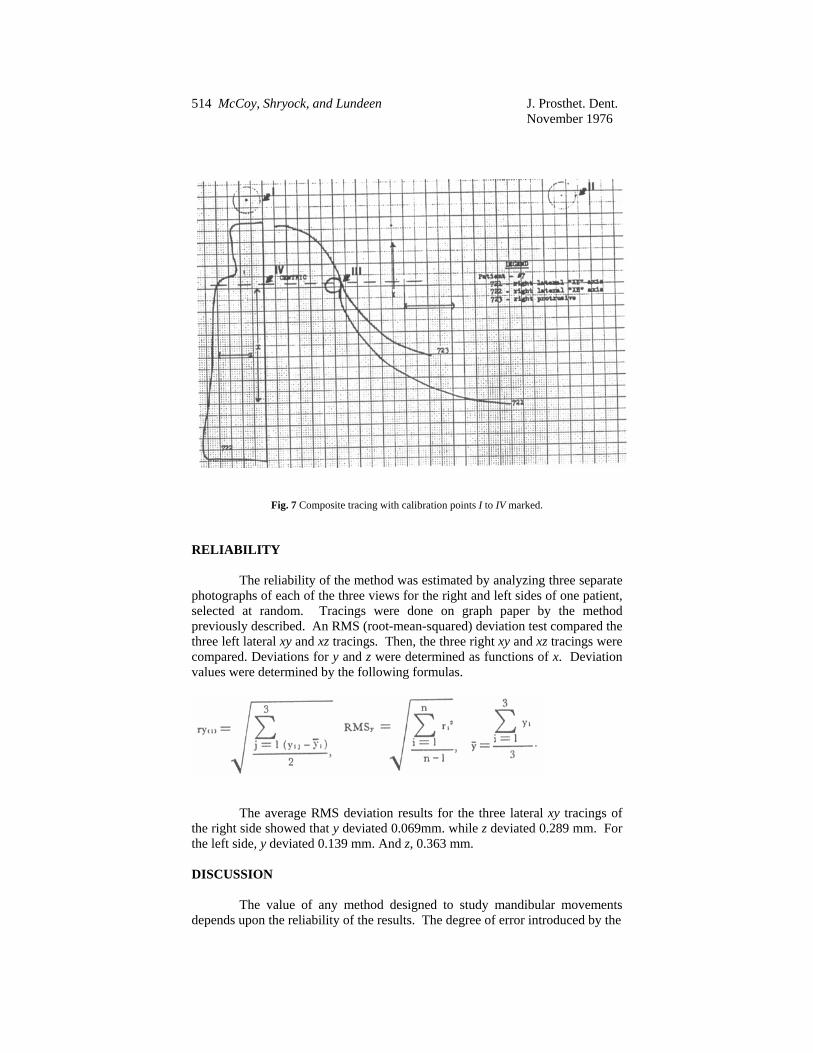
Fig. 7 Composite tracing with calibration points I to IV marked. RELIABILITY The reliability of the method was estimated by analyzing three separate photographs of each of the three views for the right and left sides of one patient, selected at random. Tracings were done on graph paper by the method previously described. An RMS (root-mean-squared) deviation test compared the three left lateral xy and xz tracings. Then, the three right xy and xz tracings were compared. Deviations for y and z were determined as functions of x. Deviation values were determined by the following formulas.
The average RMS deviation results for the three lateral xy tracings of the right side showed that y deviated 0.069mm. while z deviated 0.289 mm. For the left side, y deviated 0.139 mm. And z, 0.363 mm. DISCUSSION The value of any method designed to study mandibular movements depends upon the reliability of the results. The degree of error introduced by the

Volume 36 Computer storage of movement data 515
PATIENT 7 LEFT
Fig. 8. Composite print-out by the computer tablet of lateral xyz iformation method described in this report appears to be very small. The maximum deviation (0.363 mm.) was felt to justify continuation of future mandibular-movement analyses. Once the xyz data were stored in computer memory, any number of programs could be devised to study pertinent mandibular movements. Since the centric point was marked (flagged) on the computer-stored data, any initial measurements from this point could be accurately determined, e.g., angle of the articular eminence, Bennett angle, etc. Electronic sensors relaying mandibular-movememt information directly to the computer could be faster and more accurate than the photographic method described in this report. However, there are some advantages for using this photographic method.
(1) The method provides reference points along the way which make possible the correction of unforeseen errors, as well as evaluation of each step as it is accomplished.
(2) The cost involved for devising elaborate electronic tracking system is not necessary. A simple platform, camera, telephoto lens, projector or magnifier, and an adequte computer center are the only necessary equipment.
(3) Information can be transferred to computer memory at a convenient time, rather than requiring patient, equipment, and dentist to be available all at the same time.

516 McCoy, Shryock, and Lundeen J. Prosthet. Dent November 1976 SUMMARY AND CONCLUSIONS A method was briefly described which photographed engraved blocks of mandibular-movement recordings and transferred the information into computer memory. A photographic platform was designed to allow uniform photographing of the engraved blocks. The photographed information was then projected onto graph paper where it was traced. The traced information, with the centric point was labeled was transferred into computer memory via a Computek 531 tablet. An RMS (root-mean-squared) deviation test was conducted to estmate the reliability of this technique. The maximum deviation (0.363 mm.) was found for the z coordinate of the left-side recording. Labeling the centric point in computer memory is very important. This allows careful and detailed study of movements in the area where clinical evaluation is of utmost importance to the dentist. As more data are collected and evaluated, questions related to occlusion, such as tooth stability, effect on periodontal health, relationship to orthodontic success, and the like, may be clarified. References 1 Lee. R.L.: Jaw Movements Engraved in Solid Plastic for Articulator Controls, Part I. Recording Apparatus, J. Prosthet. Dent. 22: 209-224, 1969. 2 Lundeen, H.D., and Wirth, C.G.: Condylar Movement Patterns Engraved in Plastic Blocks, J. Prosthet. Dent. 30: 866-875, 1973. 3 Corbett, N.E., DeVincenzo, J.P., Huffer, R.A., et al.: The Relation of the Condylar Path to the Articular Eminence in Mandibular Protrusion, Angle Orthod. 41: 286-292, 1971. Dr. McCoy National Navel Dental Center Bethesda, MD 20014 Drs. Shryock and Lundeen University of Florida College of Dentistry Gainesville, FL 32610

![[PPT]Introduction to Fixed Prosthodontics - TOP … · Web viewIntroduction to Fixed Prosthodontics Dr. William Morgan Clinical Professor UCLA School of Dentistry April 3, 2007 Faculty](https://img.dokumen.tips/doc/110x75/5b1f56977f8b9a020b8b46ea/pptintroduction-to-fixed-prosthodontics-top-web-viewintroduction-to-fixed.jpg)


![Pontics [Fixed Prosthodontics Seminar @AmCoFam]](https://img.dokumen.tips/doc/110x75/5571fe2a49795991699ac64b/pontics-fixed-prosthodontics-seminar-amcofam.jpg)