Embed Size (px)
Citation preview
BP/N LS10031-000FL-E:B ECN 13-707
Document LS10031-000FL-E9/4/2013 Rev:
Firefighter’s Telephone
ECC-FFTInstruction Manual

2 ECC-FFT Instruction Manual — P/N LS10031-000FL-E:B 9/4/2013
Fire Alarm & Emergency Communication System LimitationsWhile a life safety system may lower insurance rates, it is not a substitute for life and property insurance!An automatic fire alarm system—typically made up of smoke detectors, heat detectors, manual pull stations, audible warning devices, and a fire alarm control panel (FACP) with remote notifi-cation capability—can provide early warning of a developing fire. Such a system, however, does not assure protection against property damage or loss of life resulting from a fire.
An emergency communication system—typically made up of an automatic fire alarm system (as described above) and a life safety communication system that may include an autonomous control unit (ACU), local operating console (LOC), voice commu-nication, and other various interoperable communication meth-ods—can broadcast a mass notification message. Such a system, however, does not assure protection against property damage or loss of life resulting from a fire or life safety event.
The Manufacturer recommends that smoke and/or heat detectors be located throughout a protected premises following the recommendations of the National Fire Protection Association Standard 72 (NFPA 72), manufacturer's recommendations, State and local codes, and the recommendations contained in the Guide for Proper Use of System Smoke Detectors, which is made available at no charge to all installing dealers. This document can be found at http://www.systemsensor.com/appguides/. A study by the Federal Emergency Management Agency (an agency of the United States government) indicated that smoke detectors may not go off in as many as 35% of all fires. While fire alarm systems are designed to provide early warning against fire, they do not guarantee warning or protection against fire. A fire alarm system may not provide timely or adequate warning, or simply may not function, for a variety of reasons:
Smoke detectors may not sense fire where smoke cannot reach the detectors such as in chimneys, in or behind walls, on roofs, or on the other side of closed doors. Smoke detectors also may not sense a fire on another level or floor of a building. A second-floor detector, for example, may not sense a first-floor or basement fire.
Particles of combustion or “smoke” from a developing fire may not reach the sensing chambers of smoke detectors because:
• Barriers such as closed or partially closed doors, walls, chim-neys, even wet or humid areas may inhibit particle or smoke flow.
• Smoke particles may become “cold,” stratify, and not reach the ceiling or upper walls where detectors are located.
• Smoke particles may be blown away from detectors by air outlets, such as air conditioning vents.
• Smoke particles may be drawn into air returns before reach-ing the detector.
The amount of “smoke” present may be insufficient to alarm smoke detectors. Smoke detectors are designed to alarm at var-ious levels of smoke density. If such density levels are not cre-ated by a developing fire at the location of detectors, the detectors will not go into alarm.
Smoke detectors, even when working properly, have sensing limitations. Detectors that have photoelectronic sensing cham-bers tend to detect smoldering fires better than flaming fires, which have little visible smoke. Detectors that have ionizing-type sensing chambers tend to detect fast-flaming fires better than smoldering fires. Because fires develop in different ways and are often unpredictable in their growth, neither type of detector is necessarily best and a given type of detector may not provide adequate warning of a fire.
Smoke detectors cannot be expected to provide adequate warn-ing of fires caused by arson, children playing with matches (especially in bedrooms), smoking in bed, and violent explosions
(caused by escaping gas, improper storage of flammable materi-als, etc.).
Heat detectors do not sense particles of combustion and alarm only when heat on their sensors increases at a predetermined rate or reaches a predetermined level. Rate-of-rise heat detec-tors may be subject to reduced sensitivity over time. For this reason, the rate-of-rise feature of each detector should be tested at least once per year by a qualified fire protection specialist. Heat detectors are designed to protect property, not life.
IMPORTANT! Smoke detectors must be installed in the same room as the control panel and in rooms used by the system for the connection of alarm transmission wiring, communications, signaling, and/or power. If detectors are not so located, a devel-oping fire may damage the alarm system, compromising its abil-ity to report a fire.
Audible warning devices such as bells, horns, strobes, speakers and displays may not alert people if these devices are located on the other side of closed or partly open doors or are located on another floor of a building. Any warning device may fail to alert people with a disability or those who have recently consumed drugs, alcohol, or medication. Please note that:
• An emergency communication system may take priority over a fire alarm system in the event of a life safety emergency.
• Voice messaging systems must be designed to meet intelligi-bility requirements as defined by NFPA, local codes, and Authorities Having Jurisdiction (AHJ).
• Language and instructional requirements must be clearly dis-seminated on any local displays.
• Strobes can, under certain circumstances, cause seizures in people with conditions such as epilepsy.
• Studies have shown that certain people, even when they hear a fire alarm signal, do not respond to or comprehend the meaning of the signal. Audible devices, such as horns and bells, can have different tonal patterns and frequencies. It is the property owner's responsibility to conduct fire drills and other training exercises to make people aware of fire alarm signals and instruct them on the proper reaction to alarm sig-nals.
• In rare instances, the sounding of a warning device can cause temporary or permanent hearing loss.
A life safety system will not operate without any electrical power. If AC power fails, the system will operate from standby batteries only for a specified time and only if the batteries have been properly maintained and replaced regularly.
Equipment used in the system may not be technically compat-ible with the control panel. It is essential to use only equipment listed for service with your control panel.
Telephone lines needed to transmit alarm signals from a prem-ises to a central monitoring station may be out of service or tem-porarily disabled. For added protection against telephone line failure, backup radio transmission systems are recommended.
The most common cause of life safety system malfunction is inadequate maintenance. To keep the entire life safety system in excellent working order, ongoing maintenance is required per the manufacturer's recommendations, and UL and NFPA stan-dards. At a minimum, the requirements of NFPA 72 shall be fol-lowed. Environments with large amounts of dust, dirt, or high air velocity require more frequent maintenance. A maintenance agreement should be arranged through the local manufacturer's representative. Maintenance should be scheduled monthly or as required by National and/or local fire codes and should be per-formed by authorized professional life saftety system installers only. Adequate written records of all inspections should be kept.
Limit-D-1-2013

ECC-FFT Instruction Manual — P/N LS10031-000FL-E:B 9/4/2013 3
Installation PrecautionsAdherence to the following will aid in problem-free installation with long-term reliability:WARNING - Several different sources of power can be connected to the fire alarm control panel. Disconnect all sources of power before servicing. Control unit and associ-ated equipment may be damaged by removing and/or insert-ing cards, modules, or interconnecting cables while the unit is energized. Do not attempt to install, service, or operate this unit until manuals are read and understood.
CAUTION - System Re-acceptance Test after Software Changes: To ensure proper system operation, this product must be tested in accordance with NFPA 72 after any pro-gramming operation or change in site-specific software. Re-acceptance testing is required after any change, addition or deletion of system components, or after any modification, repair or adjustment to system hardware or wiring. All compo-nents, circuits, system operations, or software functions known to be affected by a change must be 100% tested. In addition, to ensure that other operations are not inadvertently affected, at least 10% of initiating devices that are not directly affected by the change, up to a maximum of 50 devices, must also be tested and proper system operation verified.
This system meets NFPA requirements for operation at 0-49º C/32-120º F and at a relative humidity 93% ± 2% RH (non-condensing) at 32°C ± 2°C (90°F ± 3°F). However, the useful life of the system's standby batteries and the electronic com-ponents may be adversely affected by extreme temperature ranges and humidity. Therefore, it is recommended that this system and its peripherals be installed in an environment with a normal room temperature of 15-27º C/60-80º F.
Verify that wire sizes are adequate for all initiating and indi-cating device loops. Most devices cannot tolerate more than a 10% I.R. drop from the specified device voltage.
Like all solid state electronic devices, this system may operate erratically or can be damaged when subjected to light-ning induced transients. Although no system is completely immune from lightning transients and interference, proper grounding will reduce susceptibility. Overhead or outside aerial wiring is not recommended, due to an increased susceptibility to nearby lightning strikes. Consult with the Technical Ser-vices Department if any problems are anticipated or encoun-tered.
Disconnect AC power and batteries prior to removing or inserting circuit boards. Failure to do so can damage circuits.
Remove all electronic assemblies prior to any drilling, filing, reaming, or punching of the enclosure. When possible, make all cable entries from the sides or rear. Before making modifi-cations, verify that they will not interfere with battery, trans-former, or printed circuit board location.
Do not tighten screw terminals more than 9 in-lbs. Over-tightening may damage threads, resulting in reduced terminal contact pressure and difficulty with screw terminal removal.
This system contains static-sensitive components. Always ground yourself with a proper wrist strap before han-dling any circuits so that static charges are removed from the body. Use static suppressive packaging to protect electronic assemblies removed from the unit.
Follow the instructions in the installation, operating, and pro-gramming manuals. These instructions must be followed to avoid damage to the control panel and associated equipment. FACP operation and reliability depend upon proper installation.
Precau-D1-9-2005
FCC WarningWARNING: This equipment generates, uses, and can radiate radio frequency energy and if not installed and used in accordance with the instruction manual may cause interference to radio communications. It has been tested and found to comply with the limits for class A computing devices pursuant to Subpart B of Part 15 of FCC Rules, which is designed to provide reasonable protection against such interference when devices are operated in a commercial environment. Operation of this equipment in a residential area is likely to cause interfer-ence, in which case the user will be required to correct the interference at his or her own expense.
Canadian Requirements
This digital apparatus does not exceed the Class A limits for radiation noise emissions from digital apparatus set out in the Radio Interference Regulations of the Cana-dian Department of Communications.
Le present appareil numerique n'emet pas de bruits radioelectriques depassant les limites applicables aux appareils numeriques de la classe A prescrites dans le Reglement sur le brouillage radioelectrique edicte par le ministere des Communications du Canada.
LiteSpeed™ is a trademark; and FireLite® Alarms is a registered trademark of Honeywell International Inc. Microsoft® and Windows® are registeredtrademarks of the Microsoft Corporation.
©2013 by Honeywell International Inc. All rights reserved. Unauthorized use of this document is strictly prohibited.

4 ECC-FFT Instruction Manual — P/N LS10031-000FL-E:B 9/4/2013
Software DownloadsIn order to supply the latest features and functionality in fire alarm and life safety technology to our customers, we make frequent upgrades to the embedded software in our products. To ensure that you are installing and programming the latest features, we strongly recommend that you download the most current version of software for each product prior to commissioning any system. Contact Technical Support with any questions about software and the appropriate version for a specific application.
Documentation FeedbackYour feedback helps us keep our documentation up-to-date and accurate. If you have any comments or suggestions about our online Help or printed manuals, you can email us.
Please include the following information:
•Product name and version number (if applicable)
•Printed manual or online Help
•Topic Title (for online Help)
•Page number (for printed manual)
•Brief description of content you think should be improved or corrected
•Your suggestion for how to correct/improve documentation
Send email messages to:
Please note this email address is for documentation feedback only. If you have any technical issues, please contact Technical Services.

ECC-FFT Instruction Manual — P/N LS10031-000FL-E:B 9/4/2013 5
Table of Contents
Section 1: Product Description ...............................................................................................71.1: Features..........................................................................................................................................................71.2: Optional Accessories .....................................................................................................................................71.3: Compatible Devices.......................................................................................................................................71.4: ECC-FFT Board Layout ................................................................................................................................81.5: Electrical Specifications ................................................................................................................................9
1.5.1: Power Requirements............................................................................................................................91.5.2: Current Ratings....................................................................................................................................91.5.3: Wiring Specifications ........................................................................................................................10
Section 2: Installation............................................................................................................. 112.1: Mounting Options ........................................................................................................................................112.2: Backbox Installation ....................................................................................................................................112.3: Installing the ECC-FFT ...............................................................................................................................13
2.3.1: Operating Power ................................................................................................................................132.3.2: DIP switch settings on ECC-FFT ......................................................................................................13
DIP Switch............................................................................................................................................132.4: UL Power-limited Wiring Requirements.....................................................................................................142.5: ECC-FFT Fire Fighter Telephone Module Connection...............................................................................152.6: FPJ-F Installation.........................................................................................................................................162.7: SLC Device Installation...............................................................................................................................17
2.7.1: List of SLC Devices ..........................................................................................................................172.7.2: Maximum Number of Devices ..........................................................................................................172.7.3: Wiring Requirements for SLC Device ..............................................................................................17
Wiring SLC in Style 4 (Class B) Configuration...................................................................................17Wiring SLC Devices in Style 6 & 7 (Class A) Configuration .............................................................19
2.7.4: Addressing MMF-301 SLC Devices .................................................................................................192.8: Audio Phone Circuit Installation .................................................................................................................20
2.8.1: Maximum Number of Devices ..........................................................................................................202.8.2: Wiring Requirements for the Audio Telephone Circuit ....................................................................20
Single Phone Jack Audio Circuit in Class B Configuration.................................................................21Single Phone Jack Audio Circuit in Class A Configuration.................................................................22Multi-Phone Jack Audio Circuit in Class B Configuration..................................................................23Multi-Phone Jack Audio Circuit in Class A Configuration..................................................................24Telephone Jack Only Audio Circuit .....................................................................................................25
Section 3: System Operation ................................................................................................. 273.1: Push-button Operations ...............................................................................................................................273.2: LED Operations ...........................................................................................................................................273.3: Autoprogram Operation...............................................................................................................................28

6 ECC-FFT Instruction Manual — P/N LS10031-000FL-E:B 9/4/2013
This control panel has been designed to comply with standards set forth by the following regulatory agencies:
• Underwriters Laboratories/Underwriters Laboratories Canada
• National Fire Protection Association
NFPA StandardsThis Fire Alarm Control Panel complies with the following NFPA Standards:NFPA 72 National Fire Alarm CodeNote: Audible signal appliances used in public mode applications, are required to have minimum sound levels of 75 dBA at 10 feet (3 meters) and a maximum level of 120 dBA at the minimum hearing distance from the audible appliance.To ensure that the appliance is clearly heard, the audible appliance sound level must be at least 15 dBA above the average ambient sound level or 5 dBA above the maximum sound level with a duration of at least 60 seconds, depending on which level is greater, with the sound level being measured 5 feet (1.5 meters) above the floor.Underwriters Laboratories Documents:UL 38 Manually Actuated Signaling BoxesUL 464 Audible Signaling AppliancesUL 864 Standard for Control Units for Fire Protective Signaling SystemsUL 1480 Speakers for Fire Protective Signaling SystemsUL 1481 Power Supplies for Fire Protective Signaling SystemsUL 1638 Visual Signaling AppliancesUL 1711 Amplifiers for Fire Protective Signaling SystemsUL 1971 Signaling Devices for Hearing ImpairedUL 2572 Communication and Control Units for Mass Notification SystemsNEC Article 250 GroundingNEC Article 300 Wiring MethodsNEC Article 760 Fire Protective Signaling SystemsUFC Unified Facilities Criteria UFC 4-021-01: Mass Notification SystemsApplicable Local and State Building CodesRequirements of the Local Authority Having Jurisdiction (LAHJ)Fire•Lite DocumentsFire•Lite Device Compatibility Document Document #15384ECC-50/100 Manual Document #LS10001-000FL-EECC-50/125DA Manual Document #LS10027-000FL-EMS-9200UDLS Series Manual Document #52750MS-9600(UD)LS Technical Manual Document #52646FCPS-24FS6/8 Field Charger/Power Supply Document #51883HP300ULX Power Supply Document # 52386
This product has been certified to comply with the requirements in the Standard for Control Units and Accessories for Fire Alarm Systems, UL 864, 9th Edition. Operation of this product with products not tested for UL 864, 9th Edition has not been evaluated. Such operation requires the approval of the local Authority Having Jurisdiction (AHJ).
Before proceeding, the installer should be familiar with the following documents.

ECC-FFT Instruction Manual — P/N LS10031-000FL-E:B 9/4/2013 7
Section 1: Product DescriptionAn ECC-FFT Fire Fighter Telephone System provides supervision, annunciation, and control for local and remote telephone handsets. The ECC-FFT with keypad, provides indications of phone activation, and corresponding trouble conditions.
1.1 Features• One Form-C system trouble relay - TB6
• ECC-FFT Fire Fighter Telephone module for control and annunciation of up to 24 remote telephone jacks
• A maximum of ten (10) Fire Fighter Remote Handsets (FHS-F) can be used at one time to communicate over the telephone circuit connected to the ECC-FFT
• Fire Fighter Phone Jack (FPJ-F) provides a plug-in location for the FHS-F
• Fire Fighter Handset Cabinet (FHSC-RF/SF) is used to store up to five (5) Fire Fighter Handsets (FHS-F)
• System Status LEDs
1.2 Optional AccessoriesThis manual also contains information on how to install the following compatible accessories with the FFT series equipment:
1.3 Compatible DevicesTable 1.1 lists the available FireLite fire alarm control panels/systems and power supplies compati-ble with the ECC-FFT.
Model Number Description
FPJ-F Remote Phone Jack
FHS-F Fire Fighters Remote Handset
FHSC-RF Fire Fighters Handset Cabinet Recessed
FHSC-SF Fire Fighters Handset Cabinet Surface Mount
MMF-301 Addressable Mini-Monitor Module
I300 SLC Line Isolation Module
Model Manual PN
ECC-50/100 Emergency Command Center LS10001-000FL-E
MS-9200UDLS Addressable Fire Alarm Control Panel 52750
MS-9600(UD)LS Addressable Fire Alarm Control Panel 52646
FCPS-24FS6/8 Field Charger/Power Supply 51883
Table 1.1 Compatible Powering Devices
8 ECC-FFT Instruction Manual — P/N LS10031-000FL-E:B 9/4/2013
Product Description ECC-FFT Board Layout
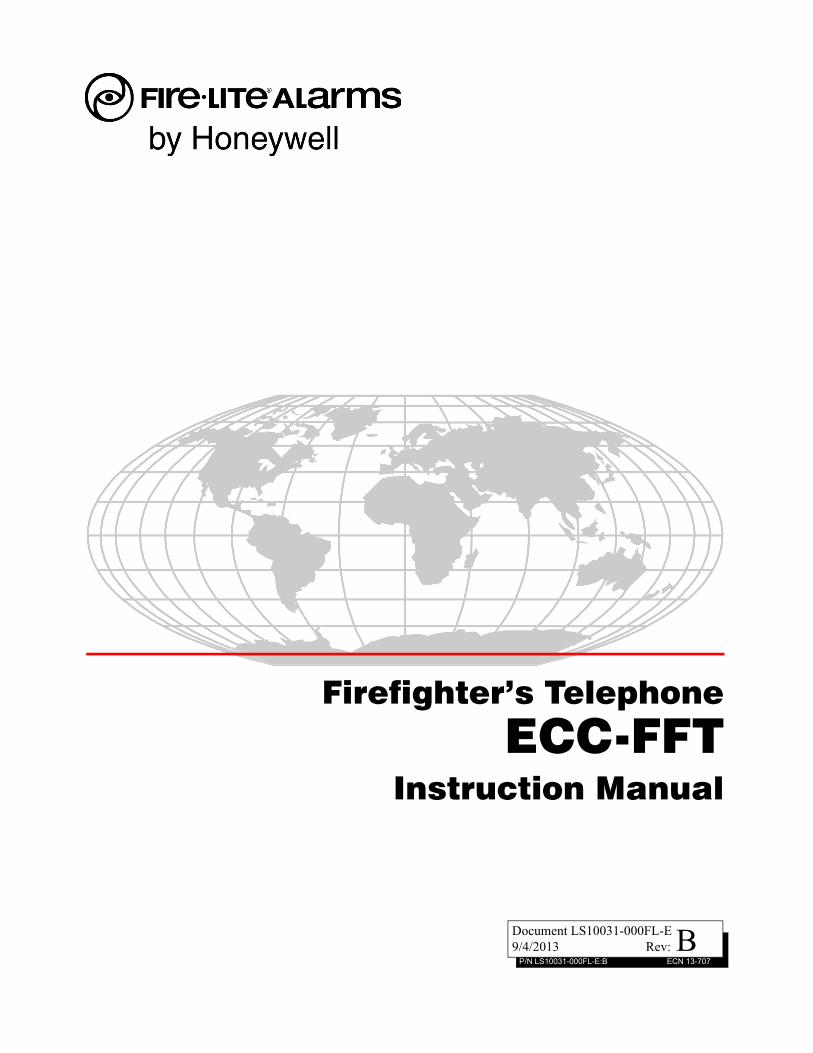
1.4 ECC-FFT Board Layout
Figure 1.1 above shows the circuit board that attaches to the cabinet. If you should need to remove the board assembly for repair, remove the seven mounting nuts which hold the assembly in the cab-inet. Then lift the control board out of the cabinet.
ON 1
23
45
6
SL
C
O
UT
SL
C
I
N
PH
ON
E O
UT
PH
ON
E
IN
-
+
-
+
-
+
-
+-
+
A
B
TR
OU
BL
EN
O C
OM
NC
1
2
3
4
Autoprogram AcceptStatus LEDs
Local Handset
piezo
Phone In
Phone Out
SLC IN
SLC Out
mounting stud
mounting studs
Supervised, Power-Limited
All circuits are inherently power-limited except the trouble relay
Not Used
DC Power
System Trouble RelayNon Power-Limited
mounting studs
mounting stud
mounting stud
Figure 1.1 Back view of ECC-FFT
DIP Switch
fftb
rd.w
mf
Power Status LED

ECC-FFT Instruction Manual — P/N LS10031-000FL-E:B 9/4/2013 9
Electrical Specifications Product Description
1.5 Electrical Specifications
1.5.1 Power Requirements
Voltage for the ECC-FFT must be a UL-listed, power-limited, filtered, non-resettable nominal 24 VDC source. The voltage source must be within the range of 17-29 VDC.
1.5.2 Current Ratings
Maximum current ratings for determining backup battery requirements for alarm (active) and standby conditions over the input voltage range of 17-29 VDC are shown in Table 1.3 below.
Zone 1-Zone 8
Zone 9 -Zone 16
Zone 17 -Zone 24
Figure 1.2 ECC-FFT Keypad
ecc
fftk
ypd.
wm
f
Circuits Voltage Current
SLC Circuit 32 V 150 mA
Audio Circuits 17 V 53 mA
Trouble Relay 12 VDC 1 A
Table 1.2 Electrical Ratings
Active Standby
ECC-FFT 230 mA 120 mA
Table 1.3 ECC-FFT Current Draw

10 ECC-FFT Instruction Manual — P/N LS10031-000FL-E:B 9/4/2013
Product Description Electrical Specifications
1.5.3 Wiring Specifications
Induced noise (transfer of electrical energy from one wire to another) can interfere with telephone communication or cause false alarms. To avoid induced noise, follow these guidelines:
• Isolate input wiring from high current output and power wiring. Do not pull one multi-conductor cable for the entire panel. Instead, separate the wiring as follows:
– SLC Loops
– Relay Circuit
– Audio Circuits
• Do not pull wires from different circuits (listed above) through the same conduit. If you must run them together, do so for as short a distance as possible or use shielded cable. Twisted, shielded wire on the Audio Circuits is recommended for maximum protection against EMI and AFI emissions and susceptibility. Connect the shield to earth ground at the panel. You must route high and low voltages separately.
• Route the wiring around the inside perimeter of the cabinet. It should not cross the circuit board where it could induce noise into the sensitive microelectronics or pick up unwanted RF noise from the high speed circuits. See Figure 2.4 for an example.
• High frequency noise, such as that produced by the inductive reactance of a speaker or bell, can also be reduced by running the wire through ferrite shield beads or by wrapping it around a ferrite toroid.
ECC-FFT Instruction Manual — P/N LS10031-000FL-E:B 9/4/2013 11
Section 2: Installation
2.1 Mounting OptionsThe cabinet may be semi-flush or surface mounted. The cabinet mounts using three key slots at the top of the backbox and two additional 0.250" diameter holes located at the bottom.
Carefully unpack the system and check for shipping damage. Mount the cabinet in a clean, dry, vibration-free area where extreme temperatures are not encountered. The area should be readily accessible with sufficient room to easily install and maintain the panel. Locate the top of the cabi-net approximately five feet above the floor with the hinge mounting on the left. Determine the number of conductors required for the devices to be installed. Sufficient knockouts are provided for wiring convenience. Select the appropriate knockout(s) and pull the required conductors into the box. Note that knockouts are also located on the back of the cabinet. All wiring should be in accordance with the National and/or Local codes for fire alarm systems.
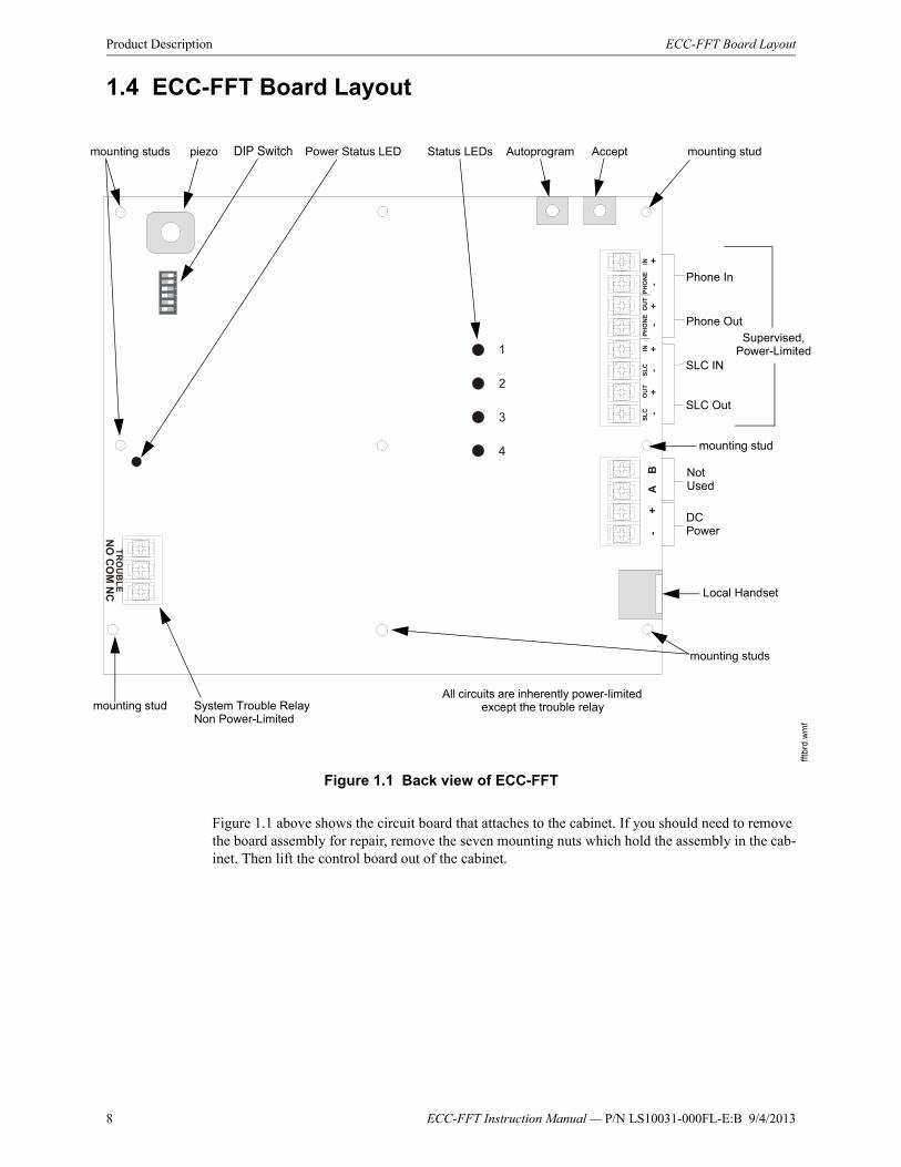
2.2 Backbox Installation
1. Open the door and lift the door off the pin hinges.
2. Loosen the two (2) screws that secure the dress panel to the backbox. Then, lift up to swing the dress panel open.
3. Disconnect the ground wire from the dress panel.
4. Lift the dress panel up and gently pull the lower hinge out of the backbox. Gently pull down to remove the top hinge. Store the dress panel in a safe place.
5. Mark and predrill hole in the wall for the center top keyhole mounting bolt using the dimensions illustrated in Figure 2.2 on page 12.
6. Install center top fastener in the wall with the screw head protruding.
! CAUTION: STATIC SENSITIVE COMPONENTSTHE CIRCUIT BOARD CONTAINS STATIC-SENSITIVE COMPONENTS. ALWAYS GROUND YOURSELF WITH A PROPER WRIST STRAP BEFORE HANDLING ANY BOARDS SO THAT STATIC CHARGES ARE REMOVED FROM THE BODY. USE STATIC SUPPRESSIVE PACKAG-ING TO PROTECT ELECTRONIC ASSEMBLIES.
ON 1
23
45
6
SL
CO
UT
SL
CIN
PH
ON
EO
UT
PH
ON
EIN
-+
-+
-+
-+
-+
AB
TR
OU
BL
EN
OC
OM
NC
1
2
3
4
remove screws
disconnectearth ground
lift up dress panel,pull out,slide down to remove
Figure 2.1 Dress Panel Removal
fft-
dpop
n.w
mf

12 ECC-FFT Instruction Manual — P/N LS10031-000FL-E:B 9/4/2013
Installation Backbox Installation
7. Place backbox over the top screw, level and secure.
8. Mark and drill the left and right upper and lower mounting holes.Note: Outer holes (closest to sidewall) are used for 16” O.C. stud mounting.
9. Install remaining fasteners and tighten.
10. Carefully reinstall the chassis assembly and dress panel by reversing the steps above. Use appropriate precautions to prevent damage to components due to static discharge.
11. Draw wires through the respective knockout locations.
An optional Trim Ring (P/N TR-CE) is available for semi-flush mount installations.
Figure 2.2 Cabinet Dimensions & Knockout Locations
905
0ud
encl
.wm
f
Semi-Flush MountingDo not recess box more than 3.875” into wall to avoid covering venting holes on top of box.
Hinge Slot for Dress Panel
Hinge Slot for Dress Panel
Semi-flush mounting hole
Mounting slots for optional Trim Ring

ECC-FFT Instruction Manual — P/N LS10031-000FL-E:B 9/4/2013 13
Installing the ECC-FFT Installation
2.3 Installing the ECC-FFT
2.3.1 Operating Power
Connect the ECC-FFT to the appropriate DC power source. See Section 1.3 for compatible equip-ment and Section 1.5 for power requirements.
2.3.2 DIP switch settings on ECC-FFT
Use the on-board DIP switch to assign the configuration setting to the ECC-FFT.
1. Refer to Figure 2.3 for location of the DIP switches on the ECC-FFT board.
2. Configure the ECC-FFT using the dip switch settings in Table 2.1. Add SLC modules to the system through Autoprogram feature. See Section 3.3 for Autoprogram Operation.
DIP Switch
DIP Switch ON OFF
1 SLC Devices Installed SLC Devices not Installed
2 Trouble Piezo Enabled Trouble Piezo Disabled
3 SLC Class A Supervision SLC Class B Supervision
4 Phone Circuit Class A Supervision Phone Circuit Class B Supervision
5 Not Used Leave in OFF position
6 Not Used Leave in OFF position
Table 2.1 ECC-FFT DIP Switch Configurations
Figure 2.3 DIP Switch
14 ECC-FFT Instruction Manual — P/N LS10031-000FL-E:B 9/4/2013
Installation UL Power-limited Wiring Requirements
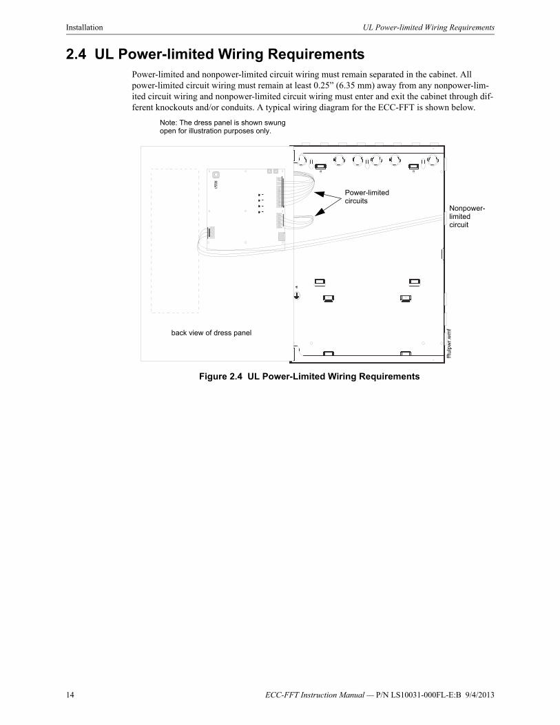
2.4 UL Power-limited Wiring RequirementsPower-limited and nonpower-limited circuit wiring must remain separated in the cabinet. All power-limited circuit wiring must remain at least 0.25” (6.35 mm) away from any nonpower-lim-ited circuit wiring and nonpower-limited circuit wiring must enter and exit the cabinet through dif-ferent knockouts and/or conduits. A typical wiring diagram for the ECC-FFT is shown below.
Figure 2.4 UL Power-Limited Wiring Requirements
back view of dress panel
Note: The dress panel is shown swung open for illustration purposes only.
Nonpower-limited circuit
Power-limited circuits
fftu
lpw
r.w
mf
ECC-FFT Instruction Manual — P/N LS10031-000FL-E:B 9/4/2013 15
ECC-FFT Fire Fighter Telephone Module Connection Installation
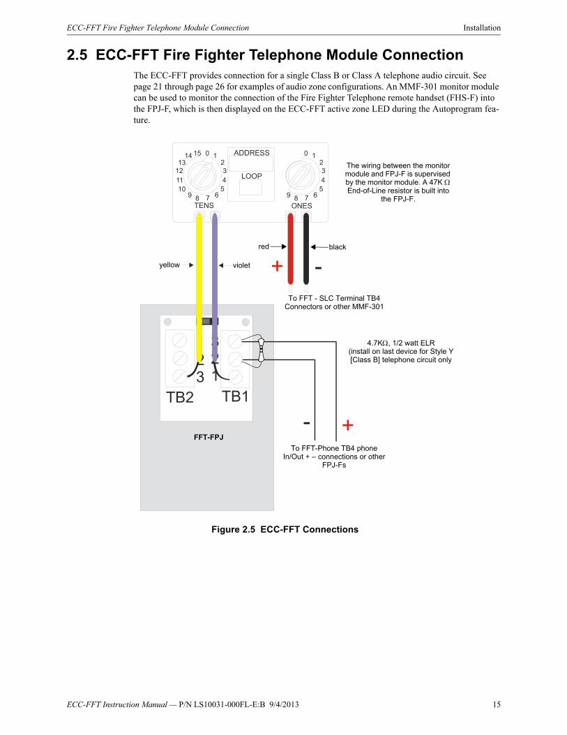
2.5 ECC-FFT Fire Fighter Telephone Module ConnectionThe ECC-FFT provides connection for a single Class B or Class A telephone audio circuit. See page 21 through page 26 for examples of audio zone configurations. An MMF-301 monitor module can be used to monitor the connection of the Fire Fighter Telephone remote handset (FHS-F) into the FPJ-F, which is then displayed on the ECC-FFT active zone LED during the Autoprogram fea-ture.
0
10111213
14 15 ADDRESS
LOOP
1234
TENS ONES
67895
0 1234
67895
TB1TB2
321
123
+ -
+ -To FFT - SLC Terminal TB4
Connectors or other MMF-301
The wiring between the monitor module and FPJ-F is supervised by the monitor module. A 47K End-of-Line resistor is built into
the FPJ-F.
To FFT-Phone TB4 phone In/Out + – connections or other
FPJ-Fs
4.7K, 1/2 watt ELR(install on last device for Style Y [Class B] telephone circuit only
FFT-FPJ
Figure 2.5 ECC-FFT Connections
violetyellow
blackred

16 ECC-FFT Instruction Manual — P/N LS10031-000FL-E:B 9/4/2013
Installation FPJ-F Installation
2.6 FPJ-F InstallationThe FPJ-F Firefighter Phone Jack mounts to a single-gang electrical box (4 x 2⅛ x 2½) or, when the addressable mini-monitor module is installed with it, a deep single-gang electrical box (4" x 2⅛” x 3¼”).
Connect the telephone audio loop between the FPJ-F and FFT as detailed below. All circuits are power-limited and supervised.
Figure 2.6 FPJ-F (Phone Jack) and FHS-F (Handset)
0
10111213
14 15 ADDRESS
LOOP
1234
TENS ONES
67895
0 1234
67895
TB1TB2
321
123
+ -
+-
SLC
PH
ON
EP
HO
NE
OU
TO
UT
ININ
SLC
-
+
-
+
-
+
-
+
Figure 2.7 FFT to FPJ-F Connection
Class A wiring
AudioAudio
To FFT-SLC terminal TB4 connectors or other MMF-301s
4.7K, ½ watt ELR (install on last device for Style Y [Class B] telephone circuit only)
contact ELR connected
FFT
FPJ-F

ECC-FFT Instruction Manual — P/N LS10031-000FL-E:B 9/4/2013 17
SLC Device Installation Installation
2.7 SLC Device Installation
2.7.1 List of SLC Devices
The following SLC device can be used with the Fire Fighters Phone. See the device installation instructions for more information (packaged with the device). Refer also to the SLC Wiring Man-ual #51309for more information.
2.7.2 Maximum Number of Devices
The ECC-FFT supports up to 24 MMF-301 devices on one FFT system.
2.7.3 Wiring Requirements for SLC Device
The following information applies to the MMF-301 - Mini Monitor module.
Wiring SLC in Style 4 (Class B) Configuration
No special wire is required for the ECC-FFT SLC loop. The wire can be untwisted, unshielded, solid or stranded as long as it meets the National Electric Code 760-51 requirements for power lim-ited fire protective signaling cables. Wire distances are computed using copper wire.
Maximum wiring resistance is 40 ohms to the farthest SLC device.
Maximum loop length depends on the wire gauge.
!WARNING: RISK OF EQUIPMENT DAMAGE AND PERSONAL INJURYSEVERAL DIFFERENT SOURCES OF POWER CAN BE CONNECTED TO THIS UNIT. ALWAYS DISCONNECT ALL SOURCES OF POWER BEFORE INSTALLING OR SERVICING.
Part Number Model Name/Description Install Sheet PN
MMF-301 Mini Monitor Module I56-3654
I300 Fault Isolator Module I56-1381
Wire Gauge Max. Distance
22 AWG 1200 feet
18 AWG 3100 feet
16 AWG 4900 feet
14 AWG 7900 feet
12 AWG 10,000 feet

18 ECC-FFT Instruction Manual — P/N LS10031-000FL-E:B 9/4/2013
Installation SLC Device Installation
Figure 2.8 and Figure 2.9 show how length is determined for out and return style wiring.
When using T-taps, the total length of all taps and the main bus must not exceed 40,000 feet. This requirement must be met in addition to the maximum distance requirements for the various wire gauges.
Figure 2.8 Calculating Wire Run Length
The dotted line path shows how the wire distance is calculated for the SLC device at the end of the run. The wire distance must be less than the maximum per wire gauge.
SLC device
SLC device
SLC device
SLC device max loop resistance = 40 ohms
SLC Circuit
Figure 2.9 Calculating Wire Run Length for a T-tap
In this example:
= 1000 feet
= 1600 feet
= 3500 feet
16 AWG wire can be used because the greatest distance is 3500 feet
The device located farthest from the SLC must be less than the maximum distance per wire gauge.
SLC device
SLC device
SLC device
SLC device max loop resistance = 40 ohms
SLC Circuit

ECC-FFT Instruction Manual — P/N LS10031-000FL-E:B 9/4/2013 19
SLC Device Installation Installation
Wiring SLC Devices in Style 6 & 7 (Class A) Configuration
Figure 2.10 illustrates how to wire the SLC loop for Style 6 or Style 7 Class A installations.
.
2.7.4 Addressing MMF-301 SLC Devices
All MMF-301 devices are addressed using the two rotary dials that appear on the device board. Use the ONES rotary dial to set the ones place in a one or two digit number, and use the TENS rotary dial to set the tens place in a two digit number.
MMF-301 modules can be assigned any unique address from 1 to 24.
NOTE: Style 6 does not require the use of short circuit isolator devices.
MMISO ISO ISO ISO ISO ISO
ISOISOISOISOISO ISO
MM MM
MMMM
MM
ISO
= SLC Device, Mini monitor module, MMF-301
= Isolator Device, I300
MMISO
ISO
MM MM
MMMM
MM MM
MM
SLC Circuit
SLC Circuit
SLC IN
SLC OUT
+
-
+
-
SLC IN
SLC OUT
+
-
+
-
Note: A maximum of 20 isolator modules can be attached to the ECC-FFT
Style 6 Wring
Style 7 Wring
Figure 2.10 Class A SLC Configuration
Wires must be in conduit and close-nippled if isolator modules are used.
Wires must be in conduit and close-nippled at the control panel and on each side of all devices.
NOTE: T-taps are not allowed on Class A SLC loops.
! CAUTION: PROPER SYSTEM SUPERVISIONFOR PROPER SYSTEM SUPERVISION DO NOT USE LOOPED WIRE UNDER TERMINALS MARKED SLC + AND – OF THE SLC DEVICE CONNECTORS. BREAK WIRE RUNS TO PROVIDE SUPERVISION OF CONNECTIONS.
20 ECC-FFT Instruction Manual — P/N LS10031-000FL-E:B 9/4/2013
Installation Audio Phone Circuit Installation
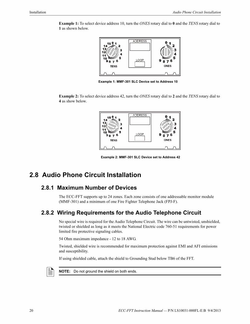
Example 1: To select device address 10, turn the ONES rotary dial to 0 and the TENS rotary dial to 1 as shown below.
Example 2: To select device address 42, turn the ONES rotary dial to 2 and the TENS rotary dial to 4 as show below.
2.8 Audio Phone Circuit Installation
2.8.1 Maximum Number of Devices
The ECC-FFT supports up to 24 zones. Each zone consists of one addressable monitor module (MMF-301) and a minimum of one Fire Fighter Telephone Jack (FPJ-F).
2.8.2 Wiring Requirements for the Audio Telephone Circuit
No special wire is required for the Audio Telephone Circuit. The wire can be untwisted, unshielded, twisted or shielded as long as it meets the National Electric code 760-51 requirements for power limited fire protective signaling cables.
54 Ohm maximum impedance - 12 to 18 AWG.
Twisted, shielded wire is recommended for maximum protection against EMI and AFI emissions and susceptibility.
If using shielded cable, attach the shield to Grounding Stud below TB6 of the FFT.
Example 1: MMF-301 SLC Device set to Address 10
Example 2: MMF-301 SLC Device set to Address 42
NOTE: Do not ground the shield on both ends.
ECC-FFT Instruction Manual — P/N LS10031-000FL-E:B 9/4/2013 21
Audio Phone Circuit Installation Installation
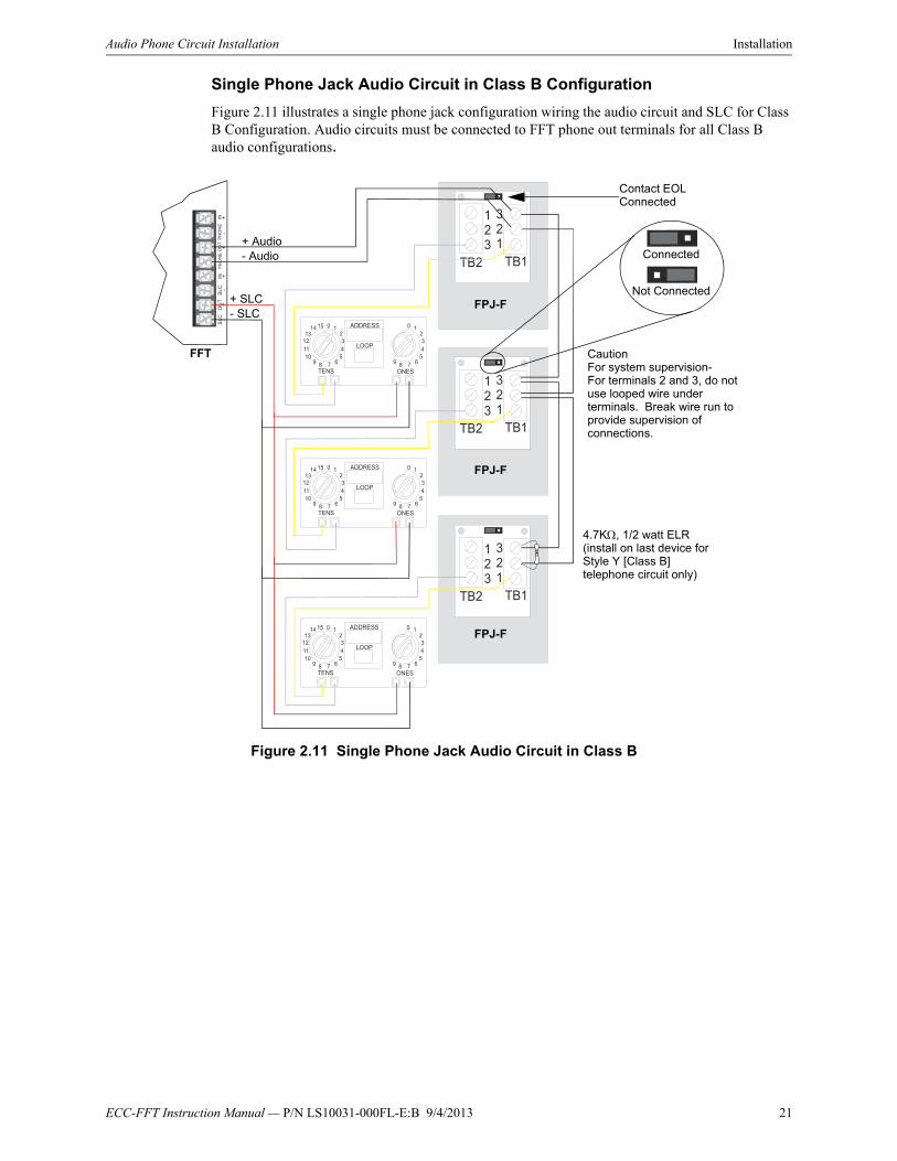
Single Phone Jack Audio Circuit in Class B Configuration
Figure 2.11 illustrates a single phone jack configuration wiring the audio circuit and SLC for Class B Configuration. Audio circuits must be connected to FFT phone out terminals for all Class B audio configurations.
0
10111213
14 15 ADDRESS
LOOP
1234
TENS ONES
67895
0 1234
67895
0
10111213
14 15 ADDRESS
LOOP
1234
TENS ONES
67895
0 1234
67895
0
10111213
14 15 ADDRESS
LOOP
1234
TENS ONES
67895
0 1234
67895
TB1TB2
321
123
TB1TB2
321
123
TB1TB2
321
123
SLC
PH
ON
EP
HO
NE
OU
TO
UT
ININ
SL
C-
+
-
+
-
+
-
+
Contact EOL Connected
+ Audio- Audio
+ SLC- SLC
CautionFor system supervision-For terminals 2 and 3, do not use looped wire under terminals. Break wire run to provide supervision of connections.
4.7K, 1/2 watt ELR (install on last device for Style Y [Class B] telephone circuit only)
Figure 2.11 Single Phone Jack Audio Circuit in Class B
FPJ-F
FPJ-F
FPJ-F
FFT
Connected
Not Connected

22 ECC-FFT Instruction Manual — P/N LS10031-000FL-E:B 9/4/2013
Installation Audio Phone Circuit Installation
Single Phone Jack Audio Circuit in Class A Configuration
Figure 2.12 illustrates a phone jack audio circuit (Class A) and SLC for Style 6 & 7 (Class A) con-figuration.
0
10111213
14 15 ADDRESS
LOOP
1234
TENS ONES
67895
0 1234
67895
0
10111213
14 15 ADDRESS
LOOP
1234
TENS ONES
67895
0 1234
67895
0
10111213
14 15 ADDRESS
LOOP
1234
TENS ONES
67895
0 1234
67895
TB1TB2
321
123
TB1TB2
321
123
TB1TB2
321
123
SLC
PH
ON
EP
HO
NE
OU
TO
UT
ININ
SLC
-
+
-
+
-
+
-
+
Figure 2.12 Single Phone Jack Audio Circuit in Class A
Contact EOL Connected
+ Audio- Audio+ Audio- Audio
+ SLC- SLC
CautionFor system supervision-For terminals 2 and 3, do not use looped wire under terminals. Break wire run to provide supervision of connections.
FPJ-F
FPJ-F
FPJ-F
FFT
+ SLCSLC -
Class A Wiring

ECC-FFT Instruction Manual — P/N LS10031-000FL-E:B 9/4/2013 23
Audio Phone Circuit Installation Installation
Multi-Phone Jack Audio Circuit in Class B Configuration
Figure 2.13 illustrates how to wire the Multi-Phone Jack audio circuit (Class B) and SLC for for Style 4 (Class B) configuration. In the Multi-Phone Jack configuration, the maximum mini-monitor contact wiring resistance between to first and last FPJ-F must be less than 100 ohms.
0
10111213
14 15 ADDRESS
LOOP
1234
TENS ONES
67895
0 1234
67895
0
10111213
14 15 ADDRESS
LOOP
1234
TENS ONES
67895
0 1234
67895
TB1TB2
321
123
TB1TB2
321
123
TB1TB2
321
123
TB1TB2
321
123
TB1TB2
321
123
TB1TB2
321
123
SLC
PH
ON
EP
HO
NE
OU
TO
UT
ININ
SLC
-
+
-
+
-
+
-
+
+ Audio- Audio Caution
For system supervision-For terminals 2 and 3, do not use looped wire under terminals. Break wire run to provide supervision of connections.
4.7K, 1/2 watt ELR (install on last device for Style Y [Class B] telephone circuit only)
FPJ-FFPJ-FFPJ-F
FFT
+ SLCSLC -
FPJ-FFPJ-FFPJ-F
Contact EOL Connected
Contact EOL Disconnected
Contact EOL Disconnected
Contact EOL Connected
Figure 2.13 Multi-Phone Jack Audio Circuit in Class B
24 ECC-FFT Instruction Manual — P/N LS10031-000FL-E:B 9/4/2013
Installation Audio Phone Circuit Installation
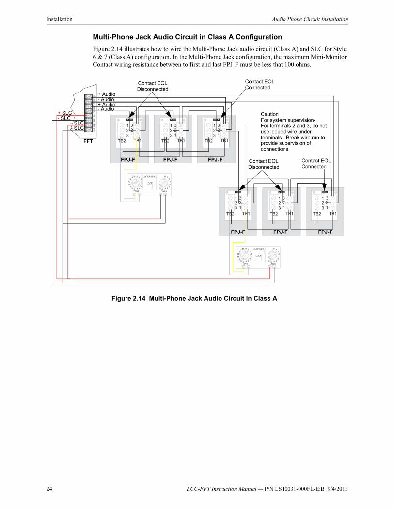
Multi-Phone Jack Audio Circuit in Class A Configuration
Figure 2.14 illustrates how to wire the Multi-Phone Jack audio circuit (Class A) and SLC for Style 6 & 7 (Class A) configuration. In the Multi-Phone Jack configuration, the maximum Mini-Monitor Contact wiring resistance between to first and last FPJ-F must be less that 100 ohms.
0
10111213
14 15 ADDRESS
LOOP
1234
TENS ONES
67895
0 1234
67895
0
10111213
14 15 ADDRESS
LOOP
1234
TENS ONES
67895
0 1234
67895
TB1TB2
321
123
TB1TB2
321
123
TB1TB2
321
123
TB1TB2
321
123
TB1TB2
321
123
TB1TB2
321
123
SL
CP
HO
NE
PH
ON
EO
UT
OU
TIN
INS
LC-
+
-
+
-
+
-
+
+ Audio- Audio+ Audio- Audio
CautionFor system supervision-For terminals 2 and 3, do not use looped wire under terminals. Break wire run to provide supervision of connections.
FPJ-FFPJ-FFPJ-F
FFT
FPJ-FFPJ-FFPJ-F
Contact EOL Connected
Contact EOL Disconnected
Contact EOL Disconnected
Contact EOL Connected
Figure 2.14 Multi-Phone Jack Audio Circuit in Class A
+ SLC- SLC
+ SLC- SLC

ECC-FFT Instruction Manual — P/N LS10031-000FL-E:B 9/4/2013 25
Audio Phone Circuit Installation Installation
Telephone Jack Only Audio Circuit
The FFT can also be configured using only the Fire Fighters Phone Jack (FPJ-F). In this configura-tion, the MMF-301 module is not required for system operation. To configure the FFT for Tele-phone Jack only, the DIP Switch position 1 must be off (SLC Devices not Installed). See Table 2.1 on page 13.
Audio wiring for this configuration is detailed below. See Figures 2.15 and 2.16.
TB1TB2
321
123
TB1TB2
321
123
TB1TB2
321
123
SLC
PH
ON
EP
HO
NE
OU
TO
UT
ININ
SL
C-
+-
+-
+-
+
+ Audio- Audio
CautionFor system supervision-For terminals 2 and 3, do not use looped wire under terminals. Break wire run to provide supervision of connections.
4.7K, 1/2 watt ELR (install on last device for Style Y [Class B] telephone circuit only)
Figure 2.15 Telephone Jack Only Audio Circuit in Class B
FPJ-F
FPJ-F
FPJ-F
FFT

26 ECC-FFT Instruction Manual — P/N LS10031-000FL-E:B 9/4/2013
Installation Audio Phone Circuit Installation
TB1TB2
321
123
TB1TB2
321
123
TB1TB2
321
123
SLC
PH
ON
EP
HO
NE
OU
TO
UT
ININ
SLC
-
+
-
+
-
+
-
+
Figure 2.16 Telephone Jack Only Audio Circuit in Class A
+ Audio- Audio+ Audio- Audio
CautionFor system supervision-For terminals 2 and 3, do not use looped wire under terminals. Break wire run to provide supervision of connections.
FPJ-F
FPJ-F
FPJ-F
FFT
Class A Wiring
ECC-FFT Instruction Manual — P/N LS10031-000FL-E:B 9/4/2013 27
Section 3: System OperationThe operation of the ECC-FFT Fire Fighter Telephone system allows audio communication from 24 remote connections through remote handsets to a single local handset. Up to 10 remote handsets can be connected and communicating at one time.
3.1 Push-button OperationsAutoprogram (on inside of FFT dress panel)
The Autoprogram key will cause the FFT to search the SLC loop for devices. The Active LED (green) will then blink for each zone where a device was found. Press and hold the Autoprogram button for 2 seconds in order to initiate this feature.
Accept (on inside of FFT dress panel)
The Accept button is used after Autoprogram. It will save the current SLC device configuration and re-initialize the FFT. If the Accept button is not pressed within one minute after the Autoprogram is complete, its configuration will be discarded and the FFT will be restarted.
Answer Call
When a remote handset is connected to one of the FPJ-F phone jacks, the Answer Call LED will blink and the FFT's piezo will sound. Pressing the Answer Call button will connect the local hand-set to the phone circuit, turn the Answer Call LED on steady, and silence the piezo. Communication between the local and remote handset is now possible. Up to ten remote handsets can be connected to the phone circuit simultaneously. After the initial remote handset, the connection of additional handsets does not cause the piezo to sound or the Answer Call LED to blink.
Trouble Silence
The Trouble Silence button is used to silence a system type trouble that has occurred in the FFT system. Once pressed, the piezo will silence.
3.2 LED OperationsPower Status LED (on Inside of FFT dress panel)
The status LED is located on the right side of the FFT board. On power-up, the power status LED will blink at a 50% on/off rate until FFT initialization is complete (which takes approximately 20 seconds). Once initialization is complete, the status LED will blink at a 10% on and 90% off rate.
No key input will be valid until the FFT completes its initialization.
Answer Call
When a remote handset connects to the audio channel, the Answer Call LED will blink and the piezo will sound. The operator at the FFT then picks up the local handset and presses the Answer button which causes the Answer Call LED to remain on steady and the piezo goes silent. Commu-nication between the local and remote handset is now established. Additional remote handsets can be attached to the audio connection without any intervention at the FFT. Once the last remote hand-set has disconnected from the FFT, the answer LED will turn off and the system will return to nor-mal.
Power
The Power LED indicates that 24 VDC is connected to the FFT.
Local Trouble
The local handset trouble LED will activate and blink when there is a problem with the local hand-set.

28 ECC-FFT Instruction Manual — P/N LS10031-000FL-E:B 9/4/2013
System Operation Autoprogram Operation
Remote Trouble
The remote handset trouble LED will activate and blink when there is a problem with the phone cir-cuit.
General Trouble
The General Trouble LED will blink active when system troubles are detected. When the Trouble Silence button is pressed, the General Trouble LED will light steady. Once all system troubles have been restored, the General Trouble LED will turn off.
Status LEDs (on Inside of FFT dress panel)
• LED 1 - SLC Supervision
• LED 2 - SLC Extra Point Detected
• LED 3 - Future Use
• LED 4 - Audio Circuit Supervision
Zone Active
Each zone has an Active LED (see Figure 3.1). The zone's Active LED will illuminate when a remote handset is plugged into that zone. The LED will turn off when the handset is removed from the zone.
Zone Trouble
Each zone has a Trouble LED. The zone's Trouble LED will blink when specific SLC issues occur such as a missing device or double address. Pressing the Trouble Silence Key will cause the zone trouble LED to turn on steady. Once the zone trouble is corrected, the LED will turn off.
3.3 Autoprogram OperationThe Autoprogram feature will attempt to locate all SLC Mini-Monitor devices installed in the sys-tem, indicate all devices found on the FFT and allow the user to accept the configuration, repeat the Autoprogram, or allow the configuration to be discarded.
1. To perform the FFT Autoprogram press and hold the Autoprogram button for 2 seconds.
2. The FFT will search for installed SLC devices and activate the Active LEDs of all zone/point addresses found.
3. When the Autoprogram is complete, the first four status LEDs will blink. The user can now press the ACCEPT key causing the FFT to save the configuration and restart.
4. The user presses the Autoprogram key again to repeat the SLC search process.
5. If the user does not press the Accept key within one minute after the Autoprogram is complete, its configuration will be discarded and the FFT will be restarted.
NOTE: Troubles that will turn these LEDs on are: SLC shorted, SLC Class A Open Trouble, and Wrong Device Type.
Trouble (yellow)
Active (green)
Figure 3.1 LED Operations

ECC-FFT Instruction Manual — P/N LS10031-000FL-E:B 9/4/2013 29
Slide-in LabelsCarefully cut along the outside of each label. Identify the keypad buttons as desired and slide the labels in. The labels slide upwards through the slits in the bottom of the keypad, covering the white spaces.Z
on
e 1
Zo
ne 2
Zo
ne 3
Zo
ne 4
Zo
ne 5
Zo
ne 6
Zo
ne 7
Zo
ne 8
Zo
ne 9
Zo
ne 10
Zo
ne 11
Zo
ne 12
Zo
ne 13
Zo
ne 14
Zo
ne 15
Zo
ne 16
Zo
ne 17
Zo
ne 18
Zo
ne 19
Zo
ne 20
Zo
ne 21
Zo
ne 22
Zo
ne 23
Zo
ne 24

30 ECC-FFT Instruction Manual — P/N LS10031-000FL-E:B 9/4/2013
Slide-in Labels Autoprogram Operation

Manufacturer Warranties and Limitation of LiabilityManufacturer Warranties. Subject to the limitations set forth herein,Manufacturer warrants that the Products manufactured by it in itsNorthford, Connecticut facility and sold by it to its authorizedDistributors shall be free, under normal use and service, from defectsin material and workmanship for a period of thirty six months (36)months from the date of manufacture (effective Jan. 1, 2009). TheProducts manufactured and sold by Manufacturer are date stamped atthe time of production. Manufacturer does not warrant Products thatare not manufactured by it in its Northford, Connecticut facility butassigns to its Distributor, to the extent possible, any warranty offeredby the manufacturer of such product. This warranty shall be void if aProduct is altered, serviced or repaired by anyone other thanManufacturer or its authorized Distributors. This warranty shall alsobe void if there is a failure to maintain the Products and the systems inwhich they operate in proper working conditions.
MANUFACTURER MAKES NO FURTHER WARRANTIES, ANDDISCLAIMS ANY AND ALL OTHER WARRANTIES, EITHEREXPRESSED OR IMPLIED, WITH RESPECT TO THE PRODUCTS,TRADEMARKS, PROGRAMS AND SERVICES RENDERED BYMANUFACTURER INCLUDING WITHOUT LIMITATION,INFRINGEMENT, TITLE, MERCHANTABILITY, OR FITNESS FORANY PARTICULAR PURPOSE. MANUFACTURER SHALL NOT BELIABLE FOR ANY PERSONAL INJURY OR DEATH WHICH MAYARISE IN THE COURSE OF, OR AS A RESULT OF, PERSONAL,COMMERCIAL OR INDUSTRIAL USES OF ITS PRODUCTS.
This document constitutes the only warranty made by Manufacturerwith respect to its products and replaces all previous warranties and isthe only warranty made by Manufacturer. No increase or alteration,written or verbal, of the obligation of this warranty is authorized.Manufacturer does not represent that its products will prevent any lossby fire or otherwise.
Warranty Claims. Manufacturer shall replace or repair, atManufacturer's discretion, each part returned by its authorizedDistributor and acknowledged by Manufacturer to be defective,provided that such part shall have been returned to Manufacturer withall charges prepaid and the authorized Distributor has completedManufacturer's Return Material Authorization form. The replacementpart shall come from Manufacturer's stock and may be new orrefurbished. THE FOREGOING IS DISTRIBUTOR'S SOLE ANDEXCLUSIVE REMEDY IN THE EVENT OF A WARRANTY CLAIM.
Warn-HL-08-2009.fm
ECC-FFT Instruction Manual — P/N LS10031-000FL-E:B 9/4/2013 31

World Headquarters1 Firelite Place
Northford, CT 06472-1653 USA203-484-7161
fax 203-484-7118
www.firelite.com