Embed Size (px)
Citation preview

Toll Free: 1-800-263-8251 Toll Free Fax: 1-800-876-1164International 1-905-335-1350 International Fax: 1-905-332-4993Email: [email protected] www.sureflowequipment.com
Page
4
• Sure Flow valves are designed and manufactured as perANSI B 16.34, API 6D & BS 5351. These standards coverPressure-Temperature ratings, minimum shell thickness andbore diameter for each size/class. Manufacturer hasachieved ISO 9001 Certificate of Registration
• We offer valve castings and trim standard perNACE MR0175-96.
• Castings inspection as per MSS - SP 53, 54, 59, 93 & 94.• Actuator mounting pad on the valve is as per ISO 5211.
Design & Testing Standards• Other applicable standards:
◆ Face to face: ANSI B 16.10
◆ Flange dimensions: ANSI B 16.5
◆ Butt welded valve ends: ANSI B 16.25
◆ Pressure tests: API 598 / B 6 6755 Part 1
◆ Fire safe: API 607 4th Edition / API 6FA /BS 6755 Part II
Two Piece Soft Seated Ball Valve
Actuator Mounting Padas per ISO-5211 in Metric/UNC
Multiple Stem Sealing
Antistatic deviceStem to BodyStem to Ball
Blow out proof stem
Fire safe metal lip
Specially designedSeat Ring
Low operating torque
Double body-gasket sealing
Materials of construction asper customer's requirements
Various end connection options
Valve operation by hand leveror gear operator or actuator
High spherocity & excellentsurface finish of ball givespositive shut off
Face to Face as per ANSI B16.10
Design FeaturesDesign Features

Toll Free: 1-800-263-8251 Toll Free Fax: 1-800-876-1164International 1-905-335-1350 International Fax: 1-905-332-4993Email: [email protected] www.sureflowequipment.com
Page
5
Size
Type End Bore ANSI 1/2" 3/4" 1" 1-1/2" 2" 3" 4" 6" 8" 10" 12"Connection Class
Two Flanged Full 150 • • • • • • • • • • •
Piece Reduced 150 • • • • • • •
Full 300 • • • • • • • • • • •
Reduced 300 • • • • • • •
Part No. Part Material Options
01 Body ASTM-A216 WCB / A351 CF8M
02 Body Adaptor ASTM-A216 WCB / A351 CF8M
03 Ball A351 CF8M
04 Stem A 479 SS316
05 Seat RPTFE
06 O Ring VITON
07 Stem Gasket RPTFE / GRAPHITE (Combination)
08 Spacer ASTM - A479 SS316
09 Cup Spring 50 Cr V4
10 Stem Nut A 194 GR8M / A 194 2H
11 Handle MS (zinc plated)
12 Stop Pin ASTM - A 479 SS316 / MS
13 Body Gasket RPTFE / GRAPHITE (Combination)
14 Stud/Bolt A 193 B8M / A 193 B7
15 Nut A 194 GR8M / A 194 2H
16 Stem Bush PHOSPHOR BRONZE
17 Stem Housing ASTM - A216 WCB / A 351 CF8M
Soft Seated Ball Valve RangeSoft Seated Ball Valve Range
Material of ConstructionMaterial of Construction
Range at a glanceRange at a glance

Toll Free: 1-800-263-8251 Toll Free Fax: 1-800-876-1164International 1-905-335-1350 International Fax: 1-905-332-4993Email: [email protected] www.sureflowequipment.com
Page
6
XXXX - XXXX - XXXXXXX - X - X - X
QUANTITYSIZESTYLE & MATERIALPORTFLANGEDOPERATOR
Examples: Include Full Description(1) 0400/BV150CS/RFL
4" 150# Carbon Steel Ball ValveReduced Bore, Flanged, Lever
(2) 0800/BV300SS/FFG8" 300# Stainless Steel Ball ValveFull Bore, Flanged, Gear
SIZE 0050 - 1/2" 0075 - 3/4" 0100 - 1" 0150 - 1 1/2"0200 - 2" 0300 - 3" 0400 - 4" 0600 - 6"0800 - 8" 1000 - 10" 1200 - 12"
BODY BV150CS 150#CLASS CS ASTM-A216 WCBSTYLE & BV150SS 150#CLASS SS ASTM-A351 CF8M
BV 300CS 300#CLASS CS ASTM-A216 WCBBV300SS 300#CLASS SS ASTM-A351 CF8M
PORT F - FULL BORER - REDUCED BORE
FLANGE Face to Face ANSI B 16.10Flange Dimension ANSI B 16.5
OPERATOR B - Bare StemL - LeverG - Gear w/ wheel
F
Ordering InformationOrdering Information

Toll Free: 1-800-263-8251 Toll Free Fax: 1-800-876-1164International 1-905-335-1350 International Fax: 1-905-332-4993Email: [email protected] www.sureflowequipment.com
Page
7
Lower limit Deg. F Upper limit Deg. F
WCB -20 1000
LCB -50 650
CF8 -425 1500
CF8M -425 1500
RPTFE -50 As per graph
Body
Mat
l.Se
at
800
700
600
500
400
300
200
100
0-20 0 100 200 300 400 500°F
Full Bore - 1/2" & 3/4", Reduced Bore - 1/2" To 1"
TEMPERATURE (°F)
Class 300 Body Rating
Class 150 Body Rating
A B
PRES
SURE
(psi)
800
700
600
500
400
300
200
100
0-20 0 100 200 300 400 500°F
Full Bore - 1/2" & 2-1/2", Reduced Bore - 1-1/4" To 3"
TEMPERATURE (°F)
Class 300 Body Rating
Class 150 Body Rating
A
B
PRES
SURE
(psi)
800
700
600
500
400
300
200
100
0-20 0 100 200 300 400 500°F
Full Bore - 3" & 4", Reduced Bore - 4"
TEMPERATURE (°F)
Class 300 Body Rating
Class 150 Body Rating
A
B
PRES
SURE
(psi)
800
700
600
500
400
300
200
100
0-20 0 100 200 300 400 500°F
Full Bore - 6", Reduced Bore - 4" & 8"
TEMPERATURE (°F)
Class 300 Body Rating
Class 150 Body Rating
A
B
PRES
SURE
(psi)
800
700
600
500
400
300
200
100
0-20 0 100 200 300 400 500°F
Full Bore - 8" - 10", Reduced Bore - 10" & 12"
TEMPERATURE (°F)
Class 300 Body Rating
Class 150 Body Rating
A B
PRES
SURE
(psi)
Seat Material:A = Virgin PTFE, B = RPTFEPressure - temperature seat ratings of valves are asgiven in the graph for body material A 216 - WCB.With the exception of body seat rings and primarysoft seals, all valve components are capable ofwithstanding the pressure - temperature ratings asspecified in ANSI B 16.34; BS 1560: Part II,BS 4504 : Part I or BS 5351 as applicable.
Temperature Limits:
Pressure-Temperature RatingsPressure-Temperature Ratings
Toll Free: 1-800-263-8251 Toll Free Fax: 1-800-876-1164International 1-905-335-1350 International Fax: 1-905-332-4993Email: [email protected] www.sureflowequipment.com
Page
8
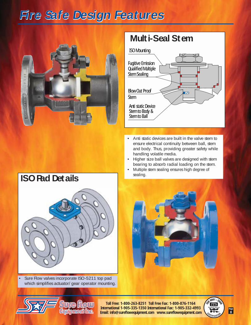
Multi-Seal Stem
ISO Pad Details
ISO Mounting
Fugitive EmissionQualified MultipleStem Sealing
Blow Out ProofStem
Anti static DeviceStem to Body &Stem to Ball
• Sure Flow valves incorporate ISO-5211 top padwhich simplifies actuator/gear operator mounting.
• Anti static devices are built in the valve stem toensure electrical continuity between ball, stemand body. Thus, providing greater safety whilehandling volatile media.
• Higher size ball valves are designed with stembearing to absorb radial loading on the stem.
• Multiple stem sealing ensures high degree ofsealing.
Fire Safe Design FeaturesFire Safe Design Features

Toll Free: 1-800-263-8251 Toll Free Fax: 1-800-876-1164International 1-905-335-1350 International Fax: 1-905-332-4993Email: [email protected] www.sureflowequipment.com
Page
9
• Fire safe conformance to API 607 (Edition IV) /API 6FA / BS-6755 Part II assures higheststandard of safety.
• Certified by customer’s inspector andindependent certifying authorities.
Fire safe tests have been witnessed and certifiedby Lloyd's Register
Body / Adapter
Seat
Secondary Sealing byFire Safe Metal LipBall
Fire Safe Design
Double BodySealing Double Body Gasket
for effective sealing
AdapterBody
• Double body gasket ensures positive body-jointsealing against pipeline stresses.
Fire Safe Design FeaturesFire Safe Design Features

Toll Free: 1-800-263-8251 Toll Free Fax: 1-800-876-1164International 1-905-335-1350 International Fax: 1-905-332-4993Email: [email protected] www.sureflowequipment.com
Page
10
Size 1/2" 3/4" 1" 1-1/2" 2" 3" 4" 6" 8" 10" 12"ANSI 150 REDUCED BORE
E1 X E .55 X .35 .75 X .55 1 X .75 1.5 X 1 2 X 1.5 3 X 2.5 4 X 3 6 X 4 8 X 6 10 X 8 12 X 10L 4.25 4.62 5.00 6.50 7.00 8.00 9.00 10.50 11.50 13.00 24.00H 2.20 3.66 3.86 5.00 6.50 7.28 8.66 9.49 12.22 - -G 4.33 7.09 7.09 8.27 8.27 11.42 17.72 17.72 26.38 - -F 3.50 3.88 4.25 5.00 6.00 7.50 9.00 11.00 13.50 16.00 19.00C 2.38 2.75 3.12 3.88 4.75 6.00 7.50 9.50 11.75 14.25 17.00R 1.38 1.69 2.00 2.88 3.62 5.00 6.19 8.50 10.62 12.75 15.00T 0.44 0.50 0.44 0.56 0.62 0.75 0.94 1.00 1.12 1.19 1.25N 0.62 0.62 0.62 0.62 0.75 0.75 0.75 0.88 0.88 1.00 1.00
No. of Holes 4 4 4 4 4 4 8 8 8 12 12O 1.16 1.99 2.19 2.62 3.43 4.48 5.44 6.28 8.25 8.21 14.55H1 0.61 1.50 1.65 1.89 2.48 3.21 3.86 4.80 6.57 10.45 11.97
ISO 5211 MTG - F05 F05 F05 F07 F07 F10 F10 F12 F14 F16WT (lb.) 3.32 5.97 7.29 13.04 19.90 46.41 61.88 97.24 172.38 397.80 563.55
ANSI 300 REDUCED BOREE1 X E .55 X .35 .75 X .55 1 X .75 1.5 X 1.25 2 X 1.5 3 X 2.5 4 X 3 6 X 4 8 X 6 10 X 8 12 X 10
L 5.50 6.00 6.50 7.50 8.50 11.12 12.00 15.88 16.50 18.00 19.75H 2.20 3.66 3.86 5.79 5.79 7.28 8.66 9.49 - - -G 4.33 7.09 7.09 8.27 8.27 11.42 17.72 17.72 - - -F 3.75 4.62 4.88 6.12 6.50 8.25 10.00 12.50 15.00 17.50 20.50C 2.62 3.25 3.50 4.50 5.00 6.62 7.88 10.62 13.00 15.25 17.75R 1.38 1.69 2.00 2.88 3.62 5.00 6.19 8.50 10.62 12.75 15.00T 0.56 0.62 0.69 0.81 0.88 1.12 1.25 1.44 1.62 1.88 2.00N 0.62 0.75 0.75 0.88 0.75 0.88 0.88 0.88 1.00 1.12 1.25
No. of Holes 4 4 4 4 8 8 8 12 12 16 16O 1.16 1.98 2.17 2.78 3.63 4.48 5.44 6.28 9.11 10.79 14.55H1 0.61 1.50 1.65 2.06 2.48 3.21 3.86 4.80 7.11 8.46 11.97
ISO 5211 MTG - F05 F05 F05 F05 F07 F10 F10 F14 F14 F16Wt. (lb.) 5.75 9.28 10.61 22.54 26.08 65.20 96.58 203.32 313.82 601.12 1200.00
• All dimensions are in inches. •Sizes 8" and above are with gear operator
Reduced Bore - Dimensions & AssemblyReduced Bore - Dimensions & Assembly

Toll Free: 1-800-263-8251 Toll Free Fax: 1-800-876-1164International 1-905-335-1350 International Fax: 1-905-332-4993Email: [email protected] www.sureflowequipment.com
Page
11
Two Piece Soft Seated Ball Valve
01
04
05
06
07
08
09
10 1211
03
02
1413 15
Stem Assembly Detailsfor 6" and 8"
Stem Assembly Detailsfor 10" and 12"
Item Part Name
01 Body02 Body Adapter03 Ball04 Stem05 Seats06 'O' Ring07 Stem Gasket08 Spacer09 Cup Spring10 Stem Nuts11 Handle12 Stop Pin13 Body Gasket14 Stud/Bolt15 Nut16 Stem Bush17 Stem Housing
04
16
06
07
04
16
17
07
Reduced Bore - Dimensions & AssemblyReduced Bore - Dimensions & Assembly

Toll Free: 1-800-263-8251 Toll Free Fax: 1-800-876-1164International 1-905-335-1350 International Fax: 1-905-332-4993Email: [email protected] www.sureflowequipment.com
Page
12
• All dimensions are in inches. •Sizes 6" and above are with gear operator
Size 1/2" 3/4" 1" 1-1/2" 2" 3" 4" 6" 8" 10" 12"ANSI 150 FULL BORE
E 0.55 0.75 1.00 1.50 2.00 3.00 4.00 6.00 8.00 10.00 12.00L 4.25 4.62 5.00 6.50 7.00 8.00 9.00 10.50 11.50 21.00 24.00H 3.66 3.86 5.00 6.50 7.01 8.66 9.65 - - - -G 7.09 7.09 8.27 8.27 11.42 17.72 17.72 - - - -F 3.50 3.88 4.25 5.00 6.00 7.50 9.00 11.00 13.50 16.00 19.00C 2.38 2.75 3.12 3.88 4.75 6.00 7.50 9.50 11.75 14.25 17.00R 1.38 1.69 2.00 2.88 3.62 5.00 6.19 8.50 10.62 12.75 15.00T 0.44 0.50 0.44 0.56 0.62 0.75 0.94 1.00 1.12 1.19 1.25N 0.62 0.62 0.62 0.62 0.75 0.75 0.75 0.88 0.88 1.00 1.00
No. of Holes 4 4 4 4 4 4 8 8 8 12 12O 1.99 2.19 2.62 3.43 4.14 5.44 6.28 8.73 10.77 14.15 20.16H1 1.50 1.65 1.89 2.48 2.85 3.86 4.72 6.57 8.46 11.57 16.26
ISO 5211 MTG F05 F05 F05 F05 F07 F10 F10 F12 F14 F16 F25WT (lb.) 5.30 6.63 9.06 17.46 24.31 55.25 66.30 137.02 361.34 508.30 906.10
ANSI 300 FULL BOREE 0.55 0.75 1.00 1.50 2.00 3.00 4.00 6.00 8.00 10.00 12.00L 5.50 6.00 6.50 7.50 8.50 11.12 12.00 15.88 16.50 22.38 25.50H 3.66 3.86 5.00 5.79 7.01 8.66 9.65 - - - -G 7.09 7.09 8.27 8.27 11.42 17.72 17.72 - - - -F 3.75 4.62 4.88 6.12 6.50 8.25 10.00 12.50 15.00 17.50 20.50C 2.62 3.25 3.50 4.50 5.00 6.62 7.88 10.62 13.00 15.25 17.75R 1.38 1.69 2.00 2.88 3.62 5.00 6.19 8.50 10.62 12.75 15.00T 0.56 0.62 0.69 0.81 0.88 1.12 1.25 1.44 1.62 1.88 2.00N 0.62 0.75 0.75 0.88 0.75 0.88 0.88 0.88 1.00 1.12 1.25
No. of Holes 4 4 4 4 8 8 8 12 12 16 16O 1.99 2.19 2.62 3.63 4.14 5.44 6.28 9.27 10.77 14.55 20.16H1 1.50 1.65 1.89 2.48 2.85 3.86 4.72 6.95 8.46 11.97 16.26
ISO 5211 MTG F05 F05 F05 F05 F07 F10 F10 F14 F14 F16 F25Wt. (lb.) 7.07 9.95 12.82 24.09 33.15 75.14 99.45 254.15 425.35 740.35 1370.20
Full Bore - Dimensions & Assembly

Toll Free: 1-800-263-8251 Toll Free Fax: 1-800-876-1164International 1-905-335-1350 International Fax: 1-905-332-4993Email: [email protected] www.sureflowequipment.com
Page
13
Two Piece Soft Seated Ball Valve
Reduced Bore
Full Bore
TL
G
0.06"
R
E 1
C FE
N
H1
O
H
Full Bore - Dimensions & Assembly

Toll Free: 1-800-263-8251 Toll Free Fax: 1-800-876-1164International 1-905-335-1350 International Fax: 1-905-332-4993Email: [email protected] www.sureflowequipment.com
Page
14
ISO TORQUE d1 d2-f8 d3 d4 h-max No of DIA. A/F Height Keyway Keyway Keyway5211 Inch-lb STUDS (d) Above Depth Width Length
FLANGE StemNut (h)
BTO RUN ETC inch inch inch UNC inch inch inch inch inch inch inch
1/2" F05 44 40 42 2.56 1.38 1.97 1/4" 0.12 4 0.47 0.31 0.35 - - -3/4" F05 80 72 76 2.56 1.38 1.97 1/4" 0.12 4 0.47 0.31 0.35 - - -1" F05 106 96 101 2.56 1.38 1.97 1/4" 0.12 4 0.63 0.39 0.56 - - -1-1/2" F05 177 159 168 2.56 1.38 1.97 1/4" 0.12 4 0.63 0.39 0.88 - - -2" F07 266 226 252 3.54 2.17 2.76 5/16" 0.12 4 0.79 0.55 0.90 - - -3" F10 752 639 677 4.92 2.76 4.02 3/8" 0.12 4 1.10 0.79 1.09 - - -4" F10 1283 1091 1155 4.92 2.76 4.02 3/8" 0.12 4 1.10 0.79 1.09 - - -6" F12 3540 2655 3186 5.91 3.35 4.92 1/2" 0.12 4 1.42 0.94 1.38 - - -8" F14 7965 5974 7169 6.89 3.94 5.51 5/8" 0.16 4 1.65 - - 1.44 0.47 1.6510" F16 13275 9965 11948 8.27 5.12 6.50 3/4" 0.20 4 2.60 - - 2.25 0.87 2.3612" F25 23895 17921 21506 11.81 7.87 10.00 5/8" 0.20 8 3.15 - - 2.82 0.87 3.58
3/4" F05 44 40 42 2.56 1.38 1.97 1/4" 0.12 4 0.47 0.31 0.35 - - -1" F05 80 72 76 2.56 1.38 1.97 1/4" 0.12 4 0.47 0.31 0.35 - - -1-1/2" F05 106 96 101 2.56 1.38 1.97 1/4" 0.12 4 0.63 0.39 0.56 - - -2" F05 177 159 168 2.56 1.38 1.97 1/4" 0.12 4 0.63 0.39 0.88 - - -3" F07 407 346 387 3.54 2.17 2.76 5/16" 0.12 4 0.79 0.55 0.90 - - -4" F10 752 639 677 4.92 2.76 4.02 3/8" 0.12 4 1.10 0.79 1.09 - - -6" F10 1283 1091 1155 4.92 2.76 4.02 3/8" 0.12 4 1.10 0.79 1.09 - - -8" F12 3540 2655 3186 5.91 3.35 4.92 1/2" 0.12 4 1.42 0.94 1.38 - - -10" F14 7965 5974 7169 6.89 3.94 5.51 5/8" 0.16 4 1.65 - - 1.44 0.47 1.6512" F16 13275 9965 11948 8.27 5.12 6.50 3/4" 0.20 4 2.60 - - 2.25 0.87 2.36
1/2" F05 71 60 66 2.56 1.38 1.97 1/4" 0.12 4 0.47 0.31 0.35 - - -3/4" F05 106 90 99 2.56 1.38 1.97 1/4" 0.12 4 0.47 0.31 0.35 - - -1" F05 159 127 148 2.56 1.38 1.97 1/4" 0.12 4 0.63 0.39 0.56 - - -1-1/2" F05 310 248 279 2.56 1.38 1.97 1/4" 0.12 4 0.63 0.39 0.88 - - -2" F07 389 312 350 3.54 2.17 2.76 5/16" 0.12 4 0.79 0.55 0.90 - - -3" F10 1151 748 1035 4.92 2.76 4.02 3/8" 0.12 4 1.10 0.79 1.09 - - -4" F10 2036 1323 1832 4.92 2.76 4.02 3/8" 0.12 4 1.10 0.79 1.09 - - -6" F14 5310 3452 4514 6.89 3.94 5.51 5/8" 0.16 4 1.65 - - 1.44 - -8" F14 11505 7478 9779 6.89 3.94 5.51 5/8" 0.16 4 1.65 - - 1.44 0.47 1.6510" F16 20355 13231 17302 8.27 5.12 5.50 3/4" 0.20 4 2.60 - - 2.25 0.87 2.3612" F25 33630 21860 28586 11.81 7.87 10.00 5/8" 0.20 8 3.15 - - 2.82 0.87 3.58
3/4" F05 71 60 66 2.56 1.38 1.97 1/4" 0.12 4 0.47 0.31 0.47 - - -1" F05 106 90 99 2.56 1.38 1.97 1/4" 0.12 4 0.47 0.31 0.47 - - -1-1/2" F05 159 127 148 2.56 1.38 1.97 1/4" 0.12 4 0.63 0.39 0.67 - - -2" F05 310 248 279 2.56 1.38 1.97 1/4" 0.12 4 0.63 0.39 0.75 - - -3" F 07 566 368 510 3.54 2.17 2.76 5/16" 0.12 4 0.79 0.55 0.87 - - -4" F10 1151 748 1035 4.92 2.76 4.02 3/8" 0.12 4 1.10 0.79 1.26 - - -6" F10 2036 1323 1832 4.92 2.76 4.02 3/8" 0.12 4 1.10 0.79 1.26 - - -8" F14 5310 3452 4514 6.89 3.94 5.51 5/8" 0.16 4 1.65 - - 1.44 0.47 1.6510" F14 11505 7478 9779 6.89 3.94 5.51 5/8" 0.16 4 1.65 - - 1.44 0.47 1.6512" F16 20355 13231 17302 8.27 5.12 6.50 3/4" 0.20 4 2.60 - - 2.25 0.87 2.36
SIZE ISO PAD DETAILS STEM END DETAILS
FB #
150
RB #
150
FB #
300
RB #
300
Torque & Operator Mounting DetailsTorque & Operator Mounting Details
Torque values mentioned above are without safety factor and we recommend 30% more for gear operator / actuator selection.BTO - Break to Open. ETC = End to Close.

Toll Free: 1-800-263-8251 Toll Free Fax: 1-800-876-1164International 1-905-335-1350 International Fax: 1-905-332-4993Email: [email protected] www.sureflowequipment.com
Page
15
All products are warranted to be free of defects in material and workmanship for a period of one year from thedate of shipment, subject to below. All custom products are not subject to return, credit or refund.
If the purchaser believes a product to be defective, the purchaser shall:
(a) Notify the manufacturer, state the alleged defect and request permission to return the product. Merchandisewill not be accepted for return without a “Return Code” clearly marked on the outside of the package.Contact the office to obtain a return code.
(b) If permission is given, return the product with the transportation prepaid. Collect shipments will not beaccepted. Goods must be returned prepaid.
If the product is accepted for return and found to be defective, the manufacturer will, at its discretion, eitherrepair or replace the product, f.o.b. factory, within 60 days of receipt, or issue credit for the purchase price.
Other than to repair, replace or credit as described above, purchaser agrees that manufacturer shall not be liablefor any loss, costs, expenses or damages of any kind arising out of the product, its use, installation orreplacement, labeling, instructions, information or technical data of any kind, description of product or use,sample or model, warnings or lack of any of the foregoing.
NO OTHER WARRANTIES, WRITTEN OR ORAL, EXPRESS OR IMPLIED, INCLUDING THE WARRANTIESOF FITNESS FOR A PARTICULAR PURPOSE AND MERCHANTABILITY, ARE MADE OR AUTHORIZED.NO AFFIRMATION OF ACT, PROMISE, DESCRIPTION OF PRODUCT OR USE OR SAMPLE OR MODELSHALL CREATE ANY WARRANTY FROM MANUFACTURER, UNLESS SIGNED BY THE PRESIDENT OFMANUFACTURER.
Sure Flow Equipment Inc. – Limited Warranty
Catalogs Available from Sure Flow Equipment
Valve OperationLength of lever and diameter of handwheel (maximum 31-1/2") of gear operator are designed to keep operating force lessthan 80 lb. All valves have a stopper for fully opened & closed position along with indicator to show position of ball port.
d 4 d 4
d 1
d 3
d 2 (f8)
ACTUATOR
MOUNTING DETAILS OFACTUATOR / GEAR OPERATOR AS PER ISO-5211
STEM END DETAILS FORLEVER OPERATED VALVES
STEM END DETAILS FORACTUATOR / GEAR OPERATOR VALVES
A/F d
HH
eigh
t Abo
veSt
em N
ut
Keyw
ayH
eigh
t
d KeywayDepth
KeywayWidth
h (M
ax)
Torque & Operator Mounting DetailsTorque & Operator Mounting Details