Embed Size (px)
Citation preview

Journal of the Serbian Society for Computational Mechanics / Vol. 3 / No. 2, 2009 / pp. 67-80
(UDC: 692.535.6:519.673)
Finite Element Modeling and Analytical Simulation of circular GLARE fiber-metal laminates subjected to lateral indentation
G. J. Tsamasphyros1 and G. S. Bikakis1*
1National Technical University of Athens, Strength of Materials Laboratory, 9 Iroon Polytechniou, Zographou, GR 157 73, Athens, Greece [email protected] *Corresponding author
Abstract
GLARE is a Fiber-Metal Laminated material used in aerospace structures which are frequently subjected to various impact damages. Hence, response of GLARE plates subjected to lateral indentation is very important. No FEM or other analytical solution of this problem is known to the authors.
This paper deals with the static response of thin circular clamped GLARE plates under the action of a lateral hemispherical indentor located at their center. We propose a finite element modeling procedure for the calculation of static load-indentation curve and the first failure load and
geo
2-2/1-0.3 plate with a radius of 40 mm. Both numerical and analytical load-indentation curves and first failures agree well with the experimental values (failure load within
ection within 5% and 3% respectively).
It is sh that our analytical results converge satisfactorily. Also, the expected governing
deflection due to glass-epoxy tensile fracture applicable to GLARE plates. Additionally, we further verify the validity of the analytical model for the solution of this problem which we have derived using the Ritz method in our previous work.
A 3-D solid modeling procedure with ANSYS is implemented. We employ an isotropic non-linear elastoplastic material model which obeys a true stress-strain relation for aluminum. An orthotropic linear elastic material model is used for the glass-epoxy. The contact between the indentor and the plate is simulated by contact elements. We use non-linear analysis with
metric and material non-linearities. The indentor is forced to move and deform the plate incrementally. Analysis stops when first failure due to glass-epoxy tensile fracture occurs. This FEM procedure and our analytical model are applied to GLARE 2-2/1-0.3 and to GLARE 3-3/2-0.4 plates with various diameters.
We compare FEM results with analytical results and their good agreement is demonstrated. Furthermore, FEM and analytical results are compared with published experimental data for the case of a GLARE
2% and 7%, failure defl
ownrole of the membrane in comparison with the bending stiffness is demonstrated. Finally, FEM plots of lateral GLARE plate deflections justify the axisymmetrical deflection shape considered by the authors.
Keywords: GLARE, laminate, indentation, fracture, FEM

G. Tsamasphyros and G. Bikakis: Finite Element Modeling and Analytical Simulation of … 68
1. Introduction
This paper focuses on the response of thin circular clamped GLARE fiber-metal laminated plates which are subjected to lateral indentation. Among other applications, GLARE is mainly used in aerospace structures and has higher impact resistance in comparison with conventional composites or aluminum alloys (Vogelesang and Vlot 2000, Vermeeren 2003).
Impact properties are very important in aerospace structures, since impact damage is caused by various sources, such as maintenance damage from dropped tools, collision between service cars or cargo and the structure, bird strikes and hail (Vogelesang and Vlot 2000, Vermeeren 2003, Vlot 1996, Vlot 1993, Laliberte et al. 2002). A large amount of the energy absorbed by GLARE plates during low velocity, high velocity or even ballistic impacts is due to the static deformation of the plate (Vlot 1996, Hoo Fat et al. 2003, Lin and Hoo Fat 2006). In this regard, the response of GLARE plates subjected to lateral indentation is very important as far as their overall impact behavior is concerned.
In this work we deal with the static response of thin circular clamped GLARE fiber-metal laminated plates under the action of a lateral hemispherical indentor located at the center of the plate. Vlot (1996) used an elastic-plastic impact model to solve this problem numerically assuming a deformation profile based on experimental data. Hoo Fatt et al. (2003) used the principle of minimum potential energy to model analytically the response of fully clamped square GLARE panels assuming a deformation profile which resembles that of a stretched membrane. They also calculated the first failure load due to glass-epoxy tensile fracture. In our previous work ( corresponding to one, two and tion of lateral indentation response applicable to thin circular GLARE plates.
s paper is to develop a finite element modeling procedure for the calculation of static load-indentation curve and the first failure load and deflection due to glass-
pplication to GLARE 2-2/1-0.3 and to GLARE 3-3/2-0.4 circular plates with various
ults and the final
ly by an indentor with a hemispherical tip of radius R acting at the
2008), we employed the Ritz method and derived formulas three-parameter approximation functions for the calcula
The first objective of thi
epoxy tensile fracture of thin circular clamped GLARE fiber-metal laminated plates under the action of a lateral hemispherical indentor located at their center. The ANSYS finite element program is used for this purpose. The second objective is to verify the validity of our analytical model (2008) by a
diameters and by comparison of analytical results with the corresponding FEM results.
We compare numerical results with analytical results and their good agreement is demonstrated. Furthermore, FEM and analytical results agree well with published experimental data for the case of a GLARE 2-2/1-0.3 plate with a radius of 40 mm (Vlot 1996). No FEM or other analytical solution of this problem is known to the authors.
In the following sections the definition of the problem is first given, then details of the FEM modeling and analytical simulation are presented followed by the obtained res
conclusions.
2. Problem definition
We consider a thin clamped circular GLARE plate with radius α and thickness t as shown in Fig. 1. The plate is loaded statical
center. The plate consists of alternating layers of aluminum and glass-epoxy. The aspect ratio α/t is assumed very high so that shear deformation and local indentation are negligible.
A polar coordinate system (r, θ, z) with the origin at the center of the plate is employed for the analytical formulation as illustrated in Fig. 1 The plate is considered clamped along its

Journal of the Serbian Society for Computational Mechanics / Vol. 3 / No. 2, 2009 69
boundary. As the indentor progresses the load P applied on the plate and the corresponding central deflection wo increase. The (P , wo) curve and the first failure load and deflection due to glass-epoxy tensile fracture will be calculated analytically and numerically using ANSYS.
P
2R
rθ
z
α
t
Fig. 1. Circular plate problem geometry and coordinate system
3. Finite element modeling
In this paper we implement a finite element modeling procedure to predict the static response of thin circular clamped GLARE fiber-metal laminated plates under the action of a lateral hemispherical indentor located at the center of the plate. ANSYS finite element program is used for this purpose.
The GLARE plate is modeled with two solid elements of different type along its thickness. The external aluminum layer, which is in contact with the indentor, is modeled with SOLID 185 elements. These hexahedral-shaped elements have eight nodes with three translational degrees of freedom per node. In order to reduce the computational cost, the remaining layers of the GLARE plate are modeled with SOLSH 190 elements. These are also hexahedral-shaped layered elements with eight nodes and three translational degrees of freedom per node. The accuracy of the
The indentor is also modeled with SOLID 185 elements. In order to simulate the contact betw
linear elastic material model with increased stiffness. We idealize the material behavior of the GLARE plate unidirectional glass-epoxy layers by employing an orthotropic linear elastic material model. The material of the GLARE plate 2024-T3 aluminum layers is modeled with an
se elements is governed by the first order shear deformation theory.
een the indentor and the external surface of the GLARE plate, we use CONTA 174 and TARGE 170 elements in way of the contact areas. The plate is clamped along its boundary. Due to symmetry of the problem we further reduce the computational cost by modeling only one quarter of the structure. Suitable symmetry boundary conditions are applied in this regard to all nodes of the symmetry planes.
The material of the steel indentor, which is considered rigid, is modeled with an isotropic

G. Tsamasphyros and G. Bikakis: Finite Element Modeling and Analytical Simulation of … 70
isotropic non-linear elastoplastic material model which obeys the following true stress-strain relation (Chandrakanth and Pandey 1998):
n
1
(1)
where σΟ is the yield stress of 2024-T3 aluminum, κ = 650 and n = 1.62.
A static non-linear analysis is employed with geometric and material non-linearities. The indentor is forced to move and deform the GLARE plate incrementally. Our analysis stops when the first failure due to glass-epoxy tensile fracture occurs. The maximum tensile strain criterion is used in order to verify when first failure occurs. The corresponding indentor’s position and load are then recorded as the first failure deflection and load.
In order to verify the convergence of FEM results, (P , wo) curve and the first failure load and deflection due to glass-epoxy tensile fracture, we built three models with increasing plate mesh density for each specific case of circular GLARE plate we analyze. A fine mesh is used for the indentor in order to represent its geometry accurately. The indentor’s mesh density remains the same for all models. A typical fine mesh of a GLARE plate along with the indentor is depicted in Fig. 2.
Fig. 2. Finite element mesh of a GLARE 2 plate with the indentor
We apply this finite element modeling procedure to GLARE 2-2/1-0.3 circular plates with 5 mm, 40 mm and 45 mm radius and to GLARE 3-3 0.4 circular plates with 65 mm, 70 mm
and 75 mm radius. A total of eighteen finite element models have been implemented. The erical results are compared with the corresponding
xperimental data for the case of a GLARE 2-2/1-0.3 pla
3 /2-
num analytical results and published e te with a radius of 40 mm (Vlot 1996).
Journal of the Serbian Society for Computational Mechanics / Vol. 3 / No. 2, 2009 71
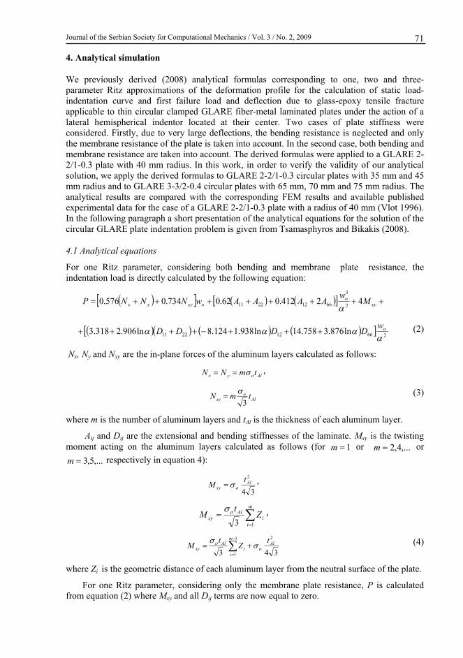
4. A
e-arameter Ritz approximations of th rofile for the calculation of s
ntation curve and first failu ion due to glass-epoxy tensilpplicable to thin circular clamped GLARE fiber-metal laminated plates under the ateral hemispherical indentor located at their center. Two cases of plate stiff
ed. Firstly, due to very large deflections, the bending resistance is neglected and only brane resistance of the plate is taken into account. In the second case, both bending and
embrane resistance are taken into account. The derived fo ulas were applied to a GLARE 2-2/1-0.3 plate with 40 mm radius. In this work, in order to verify the validity of our analytical
lution, we apply the derived formulas to GLARE 2-2/1-0.3 mm radius and to GLARE 3-3/2-0.4 circular plates with 65 mm, 70 mm and 75 mm radius. The nalytical results are compared with the corresponding FE results and available published
experimental data for the case of a GLARE 2-2/1-0.3 plate with a radius of 40 mm (Vlot 1996). the following paragraph a short presentation of the analytical eq
circular GLARE plate indentation problem is given from Tsamasphyros and Bikakis (2008).
.1 Analytical equations
For o ate resistance, the den
nalytical simulation
We previously derived (2008) analytical formulas corresponding to one, two and threp tatic load-inde e fracture
e deformation pre load and deflect
a ction of a la ness were considerthe memm rm
so circular plates with 35 mm and 45
a M
In uations for the solution of the
4
ne Ritz parameter, considering both bending and membrane pltation load is directly calculated by the following equation:
in
xyMP 4 ooxyyx
wAAAAwNNN 2412.062.0734.0576.0
2
3
66122211
266ln876.358
ow
D (2) 122211 7.14ln938.1124.8ln906.2318.3 DDD
x, Ny and Nxy are the in-plane forces of the aluminum layers calculated as follows:
Alyx tmNN
N
,
Al
oxy tmN
3
here m is the number of aluminum layers and tAl is the thickness of
(3)
w each aluminum layer.
Aij and Dij are the extensional and bending stiffnesses of the laminate. Mxy is the twisting moment acting on the aluminum layers calculated as follows (for 1m or ,...4,2m or
,.5,3m .. respectively in equation 4):
34
2Al
xy
tM
,
m
ii
Alxy Z
tM
13 ,
343
21
1
Alm
ii
Alxy
tZ
tM
here Zi is the geometric distance of each aluminum layer from the neutral surface of the plate.
For one Ritz parameter, considering only the membrane plate resistance, P is cfrom equation (2) where Mxy and all Dij terms are now equal to zero.
(4)
w
alculated

G. Tsamasphyros and G. Bikakis: Finite Element Modeling and Analytical Simulation of … 72
For two Ritz parameters, considering both bending and membrane plate re ance, the solution of the following (2x2) non-linear system of algebraic equations yields the unknown
itz coefficients λ1 and λ2 for specific values of load P (wo is obtained by adding λ1 and
2214
2213
325
3112311 324 MMMMNN 231124
sist
R λ2 ):
2P CCM xy (5)
2213
2215
322
3142213 2342 MMMNNP
224 CM xy
here:
xyyx NNNN 367.0)(288.01
M132 C (6)
w
,
xyyx NNNN 171.15)(916.112
xyyx NNNN 278.0)(218.03
(7)
,
2661222111
12103.0)(155.0
AAAAM (8
)
2661222112
12056.137)(585.205
AAAAM (9
)
2661222113
12966.12)(449.19 AAAAM (10)
2661222114
12807.0)(211.1
AAAAM ,
2661222115
12356.5)(033.8
AAAAM (1 1)
26622111
1ln938.1379.7.4(ln453.1659.1 12)ln969.0062
DDDC (12)
D
26622112 )ln447.48549.1615(985.613(ln335.36758.11141
12)ln224.24
DDDC (13)
D
2661222113
1908826.5
DDDC
For two Ritz parameters, considering only the membrane plate resistance, the unknown Ritz efficients are calculated from equations (5) and (6) where Mxy
For three Ritz parameters, considering d membrane pllution of the following (3x3) non-linear s braic equation
Ritz coefficients λ1, λ2 and λ3 for specific val (wo is obtained by adding λ1 , λ2 and ):
2214
2213
311362311 342 MMNNNP
(14) .4356.55 D
co and all Ci terms are now equal to zero.
both bending anystem of algeues of load P
ate resistance, the so s yields the unknown
λ3
3311
325 2 MMM
362311321143
22
2213
221
13232153
2112
2317 24232 CCCMMMMMM xy (15)
2NP 333 34 MMM 53 2 MMNN
352213321133
229
23283
2114
23115 24232 CCCMMMMMM xy (16)
102214352213

Journal of the Serbian Society for Computational Mechanics / Vol. 3 / No. 2, 2009 73
22114
2 213336
329
3112342516 2 MMMNNNP
3425163
2
14 MM
211532222 2422323 CCCMMMMMM xy (17)
832103173111
where:
xyyx NNNN 715.49)(046.394 ,
xyyx NNNN 459.0)(361.05 (18)
xyyx NNNN 18.0)(141.06 ,
2661222116
12737.1460)(104.2191
AAAAM (19)
1222117 825.42)(237.64 AAAM266
12A (20)
26612
12
AAM (21)
22118 976.1776)(467.2665 AA
266
12
A (22)
1222119 482.23)(223.35 AAAM
26612221110
12678.30)(016.46
AAAAM (23)
26612221111
12118.11)(677.16
AAAAM (24)
26612221112
12252.0)(378.0
AAAAM (25)
266
12A (26)
12221113 416.112 A)(625.168 AAM
26612
12835. AA
221114 (253.28 AAM 18) (27)
26612
12921.
AA
221115 (382.55 AAM (28) 36)
4 ln727.117949.11744 DC 12)ln485.78381.7411( D2211 D
266ln7
D (21
9.6 9)
15518.16078
266122211 5 976.484824.29 DDC 30)
1329.425 DD (
2661222116 967.75545.101788.12
DDDDC 1 (31)
For the unknown Ritz Ci terms are
three Ritz parameters, considering only the membrane plate resistance, coefficients are calculated from equations (15), 6) and (17) where Mxy and all now
(1 equal to zero.
First failure due to glass-epoxy tensile fracture occurs when:

G. Tsamasphyros and G. Bikakis: Finite Element Modeling and Analytical Simulation of … 74
i
jcritj j
1
22
34 , ,...3,2,1i (32)
where εcrit is the tensile failure strain of the glass-epoxy.
Depending on the number of Ritz parameters, an rane only propriate set of
d considering the case of membne resistance, we use the apresistance or the case of both bending and membra
the aforementioned equations. We start increasing the indentation load P, until the corresponding values of λj satisfy condition (32). When this happens, the indentation load P has reached the critical value Pcrit and the corresponding first failure displacement wocrit is then calculated, for those λj values, from the following equation:
i
jjow
1
, ,...3,2,1i (33)
5. Results
We have applied the propose ytical formulas to GLARE 2-2/1-0.3 plat 1-0.3 fiber-metal laminate consists of two exte ass UD fiber prepregs in the middle. Each alum reg has a thickness of 0.1 mm. Prepregs hav ular GLARE 2 plates with 35 mm, 40 mm and r our calculations are given in Table 1. All av have been used. For 2024-T3 aluminum we have (Alderliesten 2005). Remaining material prope 003) or have been calculated based on
E11 = 47.3 GPa (long. pre isson’s ratio)
d finite element modeling procedure and the anales and to GLARE 3-3/2-0.4 plates. GLARE 2-2/
rnal 2024-T3 aluminum layers and two R-glinum layer has a thickness of 0.3mm and each prepe the same orientation. We have analyzed circ45 mm radius. The material properties considered fo
ailable properties of reference (Vlot 1996) considered a Poisson’s ratio equal to 0.33
rties have been taken from Hoo Fat et al. (2the reciprocal relations.
preg stiffness) ν12 = 0.25 (prepreg Po
E22 = 17 GPa (trans. prep isson’s ratio) reg stiffness) ν13 = 0.25 (prepreg Po
E33 = 17 GPa (through thic isson’s ratio) kness stiffness) ν23 = 0.32 (prepreg Po
G12 = 7 GPa (in-plane shear modulus) εcrit = 0.055 (prepreg tensile failure strain)
G13 = 7 GP 72 GPa(aluminum Young modulus) a (out-of-plane shear modulus) EAl =
G23 = 7 GPa (out-of-plane she yield strength) ar modulus) σο = 340 ΜPa (aluminum
ratio) νAl = 0.33 (aluminum Poisson’s
Table 1. GLARE 2-2/1-0.3 material properties
GLARE 3-3/2-0.4 fiber
[2024-T3 / 00 glass / 90 glass / 2024-T3 / 90 glass / 0 glass / 2024-T3]
Each 2024-T3 aluminum layer has a thickness of 0.4 mm. Each prepreg ply has a thickness of 0.125 mm and consists of S2-glass UD fiber prepregs. We have analyzed circular GLARE 3 plates with 65 mm, 70 mm and 75 mm radius. The material properties considered for our
-metal laminate consists of the following lay-up: 0 0 0

Journal of the Serbian Society for Computational Mechanics / Vol. 3 / No. 2, 2009 75
calculations are those εcrit which, according to our correspondence with the manufactur .
The finite elem n results are presented and compared in the following paragraphs.
5.1 Finite element modeling results
In Fig. 3 the lateral deflections of a GLARE 2-2/1-0.3 circular plate under the action of the indentor are illustrated. This is a representative deflection plot for the two different GLARE grades we examine. An axisymmetrical deflection shape can be observed. This observation further enhances Vlot’s experimental results (1996) concerning the axisymmetrical deflection shape of GLARE plates, whic onsidered by Vlot for his elastic - plastic impact model. It is noted that we ha ymmetrical deflection shape for our analytical simulation (2008). In Fig. 4 a repr ed shape of a GLARE plate is depicted. For these plots we have used ANSYS symmetry expansion command in order to obtain results co of the structure. In Fig. 5 the stat adius of 40 mm are depicted.
given in Table 1, apart from er of GLARE 3, is equal to 0.047
ent modeling results and analytical simulatio
h has been cve also considered an axis
esentative deform
rresponding to a full model, since we have modeled a quarter ic (P , wo) curves of a circular GLARE 2-2/1-0.3 plate with a r
Fig. 3. L 37 mm ateral deflections in mm of a GLARE 2 plate with 40 mm radius and 4.1indentation

G. Tsamasphyros and G. Bikakis: Finite Element Modeling and Analytical Simulation of … 76
Fig. 4. Deformed shape of GLARE 2 plate with 40 mm radius
0
1
2
3
4
5
6
7
8
9
0 1 2 3 4 5 6 7 8 9
Wo [mm]
P [
KN
]
FEM fine mesh
FEM intermediatemeshFEM coarse mesh
Fig. 5. Load-indentation curves for GLARE 2 plate with 40 mm radius
o cted curves stop at the point of the predicted first failure. It can be seen that the results converge satis
5.2
o nergy of circular GLARE 2-2/1-0.3 plate with a radius of 40 mm are depicted. In Fig. 7 the static (P , wo) curves
the same GLARE 2 plate are
Apart from the (P , w ) curve which corresponds to the coarse mesh, all other depi
factorily. Similar behavior has been found in the cases of GLARE 2-2/1-0.3 plates with 35 mm, 45 mm radius and GLARE 3-3/2-0.4 plates with 65 mm, 70 mm, 75 mm radius.
Analytical simulation results
In Fig. 6 the static (P , w ) curves corresponding to the membrane strain e
corresponding to both bending and membrane strain energy ofdepicted.
Each analytical depicted curve stops at the point of the predicted first failure. It can be seen that the results converge satisfactorily in both examined cases.

Journal of the Serbian Society for Computational Mechanics / Vol. 3 / No. 2, 2009 77
0
1
2
3
4
5
0 1 2 3 4 5 6 7 8 9
P [
KN
]
Wo [mm]
1 Ritz parameter
2 Ritz parameters6
7
3 Ritz parameters
Fig. 6. Membrane Load-indentation curves for GLARE 2 plate with 40 mm radius
0
1
2
3
4
5
6
7
0 1 2 3 4 5 6 7 8 9
1 Ritz parameter
2 Ritz parameters
3 Ritz parameters
P [
KN
]
Wo [mm]
brane & Bending Load-indentation curves, GLARE 2 plate, 40 mm radius
mm, 75 mm radius.
FEM (P , wo) curve. A good agreement between numerical and analytical results is
Fig. 7. Mem
It is noted that the rigid-perfectly plastic assumption for the aluminum yields the existence of constant bending terms in (P , wo) expressions. Due to these terms the plate does not deflect until the load reaches a finite value that causes plastic flow. This is clearly illustrated in Fig. 7.
Similar behavior has been found in the cases of GLARE 2-2/1-0.3 plates with 35 mm, 45 mm radius and GLARE 3-3/2-0.4 plates with 65 mm, 70
5.3 Comparison of FEM, analytical and experimental results
In Fig. 8 the static three - parameter (P , wo) curves corresponding to the membrane strain only and to both bending and membrane strain energy are compared with the fine mesh

G. Tsamasphyros and G. Bikakis: Finite Element Modeling and Analytical Simulation of … 78
dem
d of 3.
failure defl
onstrated. The expected (Tsamasphyros and Bikakis 2008) small contribution of bending stiffness in comparison with the membrane stiffness to the response of the GLARE plates can be observed from the analytical curves. A good agreement between numerical and analytical results and the small contribution of bending stiffness in comparison with the membrane stiffness has also been found in the cases of GLARE 2-2/1-0.3 plates with 35 mm, 45 mm radius and GLARE 3-3/2-0.4 plates with 65 mm, 70 mm, 75 mm radius.
Furthermore, both numerical and analytical results are compared with the experimental (P , wo) curve published by Vlot (1996) for the case of a GLARE 2-2/1-0.3 circular plate with a radius of 40 mm. A good agreement between calculations and experimental data is found. The best numerical prediction, corresponding to the fine mesh FEM results, yields a first failure loa
75 KN and a first failure deflection of 6.65 mm which are within 2% and within 5% of the corresponding experimental values (3.8 KN and 7mm). The best analytical prediction, corresponding to the three - parameter Ritz approximation that takes into account both bending and membrane stiffness of the plate, yields a first failure load of 3.57 KN and a first
ection of 6.85 mm which are within 7% and within 3% of the corresponding experimental values.
Experiment
3 Ritz parametersmembrane & bendingFEM fine mesh5
6
7
0
1
2
3
4
P [
KN
]
3 Ritz parametersmembrane
0 1 2 3 4 5 6 7 8
Wo [mm]
Fig. 8. Experimental vs. calculated Load-indentation curves, GLARE 2 plate, 40 mm radius
6. Conclusions
we have developed a finite element modeling procedure for the prediction of the static load-indentation curve of thin circular clamped GLARE fiber-metal laminated plates that
elem modeling procedure also predicts the first failure
he nd
In this work
deflect under the action of a lateral hemispherical indentor located at their center. ANSYS finite ent program is used for this purpose. The
load and deflection due to glass-epoxy tensile fracture.
We have applied the finite element modeling procedure along with our analytical model(2008) to predict the response of circular GLARE 2-2/1-0.3 plates with 35 mm, 40 mm and 45
radius and circular GLARE 3-3/2-0.4 plates with 65 mm mm, 70 mm and 75 mm radius. Tnumerical results are compared with corresponding analytical results. Both numerical a
ytical results are compared with published experimental data from refeanal rence (Vlot 1996).

Journal of the Serbian Society for Computational Mechanics / Vol. 3 / No. 2, 2009
79
It is found that both numerical and analytical results have converged satisfactorily. The erning role of the membrane in comparison with the bending stiffness for this problem is onstrated by comparison between membrane only three-parameter Ritz approximation lts and both bending and mem
govdemresu brane three-parameter Ritz approximation results. Both
circ ll with the corresponding experimental curve
5% espectively, while the analytically calculated first failure load
FEM -indentation curve fits better with the experimental data than the analytical curves.
um ood agreement between nalytically and numerically predicted first failure load and deflection. In this regard, the
validity of our analytical model is verified.
Fine mesh plots of FEM results concerning the lateral deflections of all examined GLARE plates under lateral indentation, for all intermediate positions of the indentor, justify the axisymmetr model.
By careful at the (P , wo) curve of a GL e point of first failure, consid s of the strain energy. This c failure is not ma
The propo tion model can be used fo n and for the evaluation of t ur analytical simulation mod ponse of thin circular plates ating metal layers bonded emain valid.
Also, the ict satisfactorily the lateral inde and boundary conditions, un pon the plate. Finally, this fi rily the lateral indentation response of thin plates consisting of other advanced hybrid material systems of alternating metal layers bonded to fiber-reinforced polymer layers, provided that a suitable material model is employed for the metal layers.
References
Alderliesten R (2005). Fatigue crack propagation and delamination growth in GLARE. Delft University Press, Delft, The Netherlands.
Chandrakanth S, Pandey PC (1998). Damage coupled elasto-plastic finite elementanalysis of a Timoshenko layered beam, Computers and Structures, 69, 411-420.
Hoo Fatt MS, Lin C, Revilock Jr DM, Hopkins DA (2003). Ballistic impact of GLARETM fiber-metal laminates, Composite Structures, 61/1-2, 73-88.
Laliberte JF, Poon C, Straznicky PV, Fahr A (2002). Post-impact fatigue damage growth in fiber-metal laminates, International Journal of Fatigue, 24, 249-255.
Lin C, Hoo Fatt MS (2006). Perforation of composite plates and sandwich panels under quasi-static and projectile loading, Journal of Composite Materials, 40/20, 1801-1840.
numerically and analytically predicted load-indentation curves for a GLARE 2-2/1-0.3 ular plate with a radius of 40 mm agree we
(Vlot 1996). Also, the numerically calculated first failure load and deflection are within 2% and of their experimental values r
and deflection are within 7% and 3% of their experimental values respectively. As expected, the load
The analytical load-indentation curves are also in good agreement with the corresponding erical curves in all other examined cases. There is also a gn
a
ical deflection shape considered by Vlot (1996) and for our analytical
examination of all results we have obtained, it is concluded thARE plate under lateral indentation can be approximated up to thering only one Ritz parameter and only the membrane componentonclusion is very useful in cases where the prediction of first
ndatory, since it reduces the required calculations dramatically.
sed finite element modeling procedure and our analytical simular the design of circular GLARE plates under lateral indentatio
he impact properties of different GLARE grades. Furthermore, oel is expected to predict satisfactorily the lateral indentation res
consisting of other advanced hybrid material systems of altern to fiber-reinforced polymer layers, provided that our assumptions r
proposed finite element modeling procedure is expected to predntation response of thin GLARE plates with various geometries
der the action of hemispherical indentors with arbitrary position unite element modeling procedure is expected to predict satisfacto

G. Tsamasphyros and G. Bikakis: Finite Element Modeling and Analytical Simulation of … 80
Tsamasphyros GJ, Bikakis GS (2008). Response of Circular GLARE Fiber – Metal Laminates under Lateral Indentation. Proc. Ninth International Conference on Computational Structures Technology (CST 2008) (Eds. B.H.V. Topping and M. Papadrakakis), Athens, Greece.
metal laminates, Applied Composite Materials, 10, 189-205.
n fibre metal laminates, International Journal of Impact
, 911-
ocessing Technology, 103, 1-5
Vermeeren CAJR (2003). An historic overview of the development of fibre
Vlot A (1996). Impact loading oEngineering, 18/3, 291-307.
Vlot A (1993). Impact properties of fibre metal laminates, Composites Engineering, 3/10927.
Vogelesang LB, Vlot A (2000). Development of fibre metal laminates for advanced aerospace structures, Journal of Materials Pr