Embed Size (px)
Citation preview

Finite Element-Based Model for Crack Propagation in
Polycrystalline Materials∗
N. Sukumar1,† D. J. Srolovitz2,3
1 Department of Civil and Environmental Engineering, University ofCalifornia, Davis, CA 95616.
2 Princeton Materials Institute, Bowen Hall, Princeton University,Princeton, NJ 08544.
3 Department of Mechanical and Aerospace Engineering, PrincetonUniversity, Princeton, NJ 08544.
Abstract
In this paper, we use an extended form of the finite element method to studyfailure in polycrystalline microstructures. Quasi-static crack propagation is con-ducted using the extended finite element method (X-FEM) and microstructuresare simulated using a kinetic Monte Carlo Potts algorithm. In the X-FEM, theframework of partition of unity is used to enrich the classical finite element ap-proximation with a discontinuous function and the two-dimensional asymptoticcrack-tip fields. This enables the domain to be modeled by finite elements withoutexplicitly meshing the crack surfaces, and hence crack growth simulations can becarried out without the need for remeshing. First, the convergence of the methodfor crack problems is studied and its rate of convergence is established. Microstruc-tural calculations are carried out on a regular lattice and a constrained Delaunaytriangulation algorithm is used to mesh the microstructure. Fracture propertiesof the grain boundaries are assumed to be distinct from that of the grain interior,and the maximum energy release rate criterion is invoked to study the competitionbetween intergranular and transgranular modes of crack growth.
KEYWORDS: microstructure, grain boundaries, crack discontinuity, partition ofunity, extended finite element method, kinetic Monte Carlo, convergence
∗Journal Computational and Applied Mathematics, in press, 2004†Corresponding author. Tel.: +1-530-754-6415, E-mail: [email protected]

1 Introduction 2
1 Introduction
Microstructural features in polycrystalline materials play an important role in determin-ing the failure mechanisms as well as the macroscopic mechanical response in these class ofmaterials. In monolithic, polycrystalline materials, tailored microstructures can inducecrack bridging and kinking, leading to improved toughness and failure resistance [1].The role and influence of microstructural features (e.g., grain size and shape, and grainboundary characteristics) on fracture is well-established [2]. Experimental evidence hasdemonstrated that the fracture resistance of polycrystals can be enhanced by increasingthe fraction of so-called special boundaries and by modifying the grain boundary networkand topology [3–5]. However, theoretical and numerical models have not yet emergedthat can fully explain these experimental findings. In this paper, we use a finite element-based mesoscale fracture model that accounts for the grain structure and the differencesin the critical fracture energy of the grain boundaries vis-a-vis that of the grain interior.
Failure modeling in disordered (heterogeneous) materials has been approached usinglattice (spring-network) models [6–10], Voronoi cell-based finite element method [11], andcohesive surface formulations within finite elements [12]. Fracture strength in disorderedmaterials is governed by weakest-link statistics [13]. Spring-network models are intuitivein nature, and can be easily implemented; however, it is difficult to obtain both elastichomogeneity and grid-insensitive crack propagation directions on random lattice networks[14]. Discrete crack growth modeling with finite elements is the prevailing standard. Themodeling of arbitrary geometries with varying material properties render finite elementsas a powerful computational tool. Even though crack growth modeling with remeshinghas reached a mature stage of development [15, 16], it is not readily amenable to amicroscopic description of failure modeling and hence has not received wide attention.
Recently, there has been significant progress in the direction of discrete crack growthmodeling—the development of a partition of unity finite element method for crack mod-eling (coined as the extended finite element method or X-FEM) [17, 18] has providedan accurate and robust numerical method that removes the need to mesh the cracksurfaces in static or quasi-static crack growth simulations. In the X-FEM, the frame-work of partition of unity [19] is used to enrich the classical displacement-based finiteelement approximation with a discontinuous function (Heaviside step function) and thetwo-dimensional asymptotic crack-tip fields. This provides a means to model the crackindependently of the underlying finite element mesh. As opposed to previous develop-ments in modeling strong (displacement) discontinuities within finite elements [20], someof the noteworthy advantages of the X-FEM are: a single-field variational principle isused with no incompatibilities introduced between elements; the symmetry and sparsityof the stiffness matrix are retained; and the crack discontinuity can be totally arbitrarywith respect to the finite element mesh.
It is now well-recognized that failure modeling at the microstructural (mesoscopic)scale in heterogeneous materials is an appropriate and potentially fruitful path [21].
Sukumar and Srolovitz, 2003

2 Extended Finite Element Method 3
In this study, the incorporation of microstructure within a continuum-based partitionof unity finite element method represents a significant point of departure from priorfinite element models for fracture. The topology of polycrystalline materials and inparticular the grain structure needs to be accounted for in any realistic failure modelingendeavor. The size of the grain (e.g., grain diameter) provides a natural length-scale thatis embedded within the mesoscopic fracture model. Such an approach can lead to betterintegration of experiment and numerical modeling towards the development of a usefultool for fracture simulation in complex heterogeneous materials.
In [22], the computational algorithm for brittle fracture simulations in polycrystallinemicrostructures was presented; here, the same algorithm is used to elucidate some of thekey features of the crack growth model. In Section 2, the extended finite element methodis introduced, and in Section 3, computer simulation of polycrystalline microstructuresand the microstructural meshing algorithm are summarized. The weak form and discreteequations used in the X-FEM are presented in Section 4. In Section 5.1, a convergencestudy of the X-FEM for an edge crack problem is carried out. The crack growth procedureis outlined in Section 5.2, and numerical simulation results are presented in Section 5.3.The main conclusions obtained from this study are given in Section 6.
2 Extended Finite Element Method
The partition of unity finite element method [19] is a generalization of the standardGalerkin finite element method. In the literature, numerical techniques such as the ex-tended finite element method (X-FEM) [17, 18], generalized finite element method [23],or the element partition method [24] are all particular instances of the partition of unitymethod. In the X-FEM, the emphasis has been on modeling discontinuities (such ascracks) with minimal enrichment. Even though the idea of adding special functions tothe finite element approximation is not new [25], unlike previous attempts, the partitionof unity framework satisfies a few important properties which makes it a powerful tool forlocal enrichment within a finite element setting: (1) can incorporate application-specificbasis functions to better approximate the solution; (2) automatic enforcement of continu-ity (conforming trial and test approximations); and (3) point or line singularities in 2-d,and surface discontinuities in 3-d can be modeled without the need for the discontinuoussurfaces to be aligned with the finite element mesh. In [17], the linear elastic near-tipasymptotic fields were used as enrichment functions, whereas in [26], the asymptoticnear-tip fields for a bimaterial interface crack were adopted.
We summarize some of the essential concepts related to 2-d crack modeling in isotropicmedia [17]. For further details on the X-FEM implementation, the interested reader canrefer to References [17] and [27]. Consider a single crack in 2-dimensions. Let Γc be thecrack surface (interior) and Λc the crack tip—the closure Γc = Γc ∪ Λc. The enriched
Sukumar and Srolovitz, 2003
3 Polycrystalline Microstructure 4
displacement (trial and test) approximation for 2-d crack modeling is of the form [17]:
uh(x) =∑
I∈N
NI(x)
uI +H(x)aI︸ ︷︷ ︸
I ∈NΓ
+4∑
α=1
Φα(x)bαI
︸ ︷︷ ︸
I ∈NΛ
, (1)
where uI is the nodal displacement vector associated with the continuous part of thefinite element solution, aI is the nodal enriched degree of freedom vector associated withthe Heaviside function H (assumes the value +1 above the crack and −1 below thecrack), and bαI is the nodal enriched degree of freedom vector associated with the elasticasymptotic crack-tip functions. In the above equation, N is the set of all nodes in themesh; NΓ is the set of nodes whose shape function support is cut by the crack interiorΓc; and NΛ is the set of nodes whose shape function support is cut by the crack tip Λc
(NΓ ∩NΛ = ∅):
NΛ = nK : nK ∈ N , ωK ∩ Λc 6= ∅, (2)
NΓ = nJ : nJ ∈ N , ωJ ∩ Γc 6= ∅, nJ 6∈ NΛ. (3)
The crack-tip enrichment functions in isotropic elasticity are:
[Φα(x), α = 1–4] =
[√r sin
θ
2,√r cos
θ
2,√r sin θ sin
θ
2,√r sin θ cos
θ
2
]
, (4)
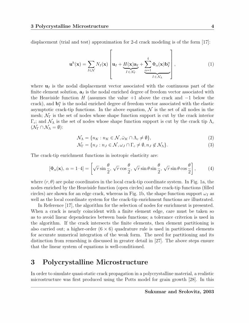
where (r, θ) are polar coordinates in the local crack-tip coordinate system. In Fig. 1a, thenodes enriched by the Heaviside function (open circles) and the crack-tip functions (filledcircles) are shown for an edge crack, whereas in Fig. 1b, the shape function support ωI aswell as the local coordinate system for the crack-tip enrichment functions are illustrated.
In Reference [17], the algorithm for the selection of nodes for enrichment is presented.When a crack is nearly coincident with a finite element edge, care must be taken soas to avoid linear dependencies between basis functions; a tolerance criterion is used inthe algorithm. If the crack intersects the finite elements, then element partitioning isalso carried out; a higher-order (6 × 6) quadrature rule is used in partitioned elementsfor accurate numerical integration of the weak form. The need for partitioning and itsdistinction from remeshing is discussed in greater detail in [27]. The above steps ensurethat the linear system of equations is well-conditioned.
3 Polycrystalline Microstructure
In order to simulate quasi-static crack propagation in a polycrystalline material, a realisticmicrostructure was first produced using the Potts model for grain growth [28]. In this
Sukumar and Srolovitz, 2003
3 Polycrystalline Microstructure 5
CRACK
(a)
rCRACK
ωΙ
I
θ
(b)
Figure 1: Enrichment for an edge crack. (a) Nodal enrichment for Heaviside (opencircles) and crack-tip (filled circles) functions; and (b) Coordinate configuration (r, θ) forcrack-tip enrichment functions.
model, a continuum microstructure is mapped onto a regular two-dimensional squarelattice containing N sites. Each lattice site is assigned a number si, which correspondsto the orientation of the grain in which it is embedded. The number of distinct grainorientations (spins) is Q. Lattice sites which are adjacent to neighboring sites havingdifferent grain orientations are regarded as being adjacent to a grain boundary, whereas asite surrounded by sites with the same grain orientation is in the grain interior. The grainboundary energy is specified by associating a positive energy with grain boundary sitesand zero energy for sites in the grain interior, in accordance with the Potts Hamiltonian:
E = J
N∑
i=1
nn(i)∑
j=1
(1− δsisj
), (5)
where J is a constant proportional to the grain boundary energy per unit length, andδij is the Kronecker delta. In Eq. (5), the summation on i is over all the sites in thelattice, whereas that on j is over the first and second nearest neighbors nn(i) of site i.The kinetics of the boundary motion are simulated via a zero-temperature Monte Carlotechnique in which a lattice site is selected at random and its orientation is randomlychanged to one of the other grain orientations. The change in energy associated withthe change in orientation is then evaluated. If the change in energy is less than or
Sukumar and Srolovitz, 2003

4 Governing Equations 6
equal to zero, the reorientation is accepted; if the energy is raised, the reorientation isrejected. Microstructures are produced by initially assigning a random value si of thegrain orientation (1 ≤ si ≤ Q) to each site. Time is measured in units of Monte Carlosteps: one MCS corresponds to N attempted changes, with the time increment ∆t = 1/NMCS after every reorientation. The Monte Carlo procedure is executed until the desiredgrain size is produced.
In the crack propagation simulations, the initial finite element mesh is based on themicrostructure generated by the Potts model. In the literature, mesh generation al-gorithms for material microstructures are available [29, 30]. In order to perform crackpropagation simulations in 2-d, we required a Delaunay triangulation meshing scheme inwhich the polycrystalline material is represented by distinct grains and the grain bound-aries are associated with one-dimensional segments (edges of the finite elements). Tomeet our needs, we developed a Delaunay algorithm to mesh the polycrystalline mi-crostructure [22]. The input to the meshing algorithm is a polycrystalline microstructureproduced by the Potts model, with known spins si (1 ≤ si ≤ Q, 1 ≤ i ≤ N). A grainboundary conforming finite element mesh is constructed using a Delaunay triangulationalgorithm [31], with a provision for local mesh refinement. Mesh refinement is based on acomparison between the actual local length scale ` (e.g., element circum-radius) and thedesired length scale specified by a scalar variable ρ called the length density function.
4 Governing Equations
4.1 Strong Form
Consider a body Ω ⊂ 2, with boundary Γ. The boundary Γ = Γu∪Γt∪mi=1 Γic, where Γuis the essential boundary, Γt the natural boundary, and Γic are the internal cracks. Thefield equations of elastostatics in the absence of body forces are:
∇ · σ = 0 in Ω, σ = C : ε, ε = ∇su, (6)
where ∇s is the symmetric gradient operator, u is the displacement vector, ε is the smallstrain tensor, σ is the Cauchy stress tensor, and C is the tensor of elastic moduli for ahomogeneous isotropic material. The essential and natural boundary conditions are:
u = u on Γu, σ · n = t on Γt, σ · n = 0 on Γic, (i = 1, 2, . . . , m), (7)
where n is the unit outward normal to Ω, u and t are prescribed displacements andtractions, respectively, and m is the number of cracks. Note that the third equality inEq. (7) imposes the condition that the crack Γic is traction-free.
Sukumar and Srolovitz, 2003
4.2 Weak Form and Discrete Equations 7
4.2 Weak Form and Discrete Equations
The weak form (principle of virtual work) for linear elastostatics is:
∫
Ωh
σ : δεh dΩ =
∫
∂Ωht
t · δuh dΓ ∀δuh ∈ Uh0 , (8)
where uh ∈ Uh and δuh ∈ Uh0 are the approximating trial and test functions used in the
X-FEM, and δ is the first variation operator. The space Uh is the enriched finite elementspace that satisfies the essential boundary conditions, and which include basis functionsthat are discontinuous across the crack surfaces. The space Uh
0 is the corresponding spacewith homogeneous essential boundary conditions. The finite element domain is Ωh andthe traction boundary conditions are imposed on ∂Ωh
t , which is a subset of ∂Ωh.The trial function uh and the test function δuh used in the X-FEM are of the form
given in Eq. (1). On substituting the trial and test functions in the above equation,and using the arbitrariness of nodal variations, the following discrete system of linearequations is obtained:
Kd = f , (9)
where d is the vector of nodal unknowns, and K and f are the global stiffness matrixand external force vector, respectively [22].
5 Numerical Results
We first test the X-FEM on a benchmark problem to check the accuracy of the stressintensity factors (SIFs) and to establish the rate of convergence of the method. The con-vergence of the numerical method is studied by imposing the exact near-tip displacementfield on the boundary of an elastic plate that contains a crack that extends from theperimeter to the center of the specimen. Then, we describe the simulation procedure forcrack growth through a microstructure and present crack growth simulations for varyinggrain boundary toughness.
5.1 Convergence Study
Consider an elastic plate of dimensions (−1, 1)× (−1, 1) with a crack of unit length thatextends from (−1, 0) to (0, 0). The Cartesian components of the near-tip displacementfield [2] corresponding to KI = 1 and KII = 1 are imposed on the boundary of the
Sukumar and Srolovitz, 2003

5.1 Convergence Study 8
specimen:
u1(r, θ) =1
4µ
√r
2π
[
(2κ− 1) cosθ
2− cos
3θ
2
]
+
[
(2κ+ 3) sinθ
2+ sin
3θ
2
]
, (10a)
u2(r, θ) =1
4µ
√r
2π
[
(2κ+ 1) sinθ
2− sin
3θ
2
]
−[
(2κ− 3) cosθ
2+ cos
3θ
2
]
, (10b)
where µ = E/2(1 + ν) is the shear modulus, E is the Young’s modulus, and ν is thePoisson’s ratio of the material. The constant κ = 3 − 4ν under plane strain conditions.The mixed mode SIFs are computed using the domain form [32] of the interaction integral[33]. The radius of the domain rd = rkhe, where he is the mesh spacing and rk is a scalarmultiple. All elements that lie within a radius of rd from the crack-tip are selected toform the 2-d domain that is used in the domain integral computations; for further detailson the SIF computations in the X-FEM, see [17].
The stress intensity factors and the relative error in the energy norm are computed asthe mesh is refined. The exact energy norm and the error in the energy norm are definedas:
‖u‖E(Ω) =(1
2
∫
Ω
εTCε dΩ
)1/2
, ‖u− uh‖E(Ω) =(1
2
∫
Ω
(ε− εh)TC(ε− εh) dΩ)1/2
. (11)
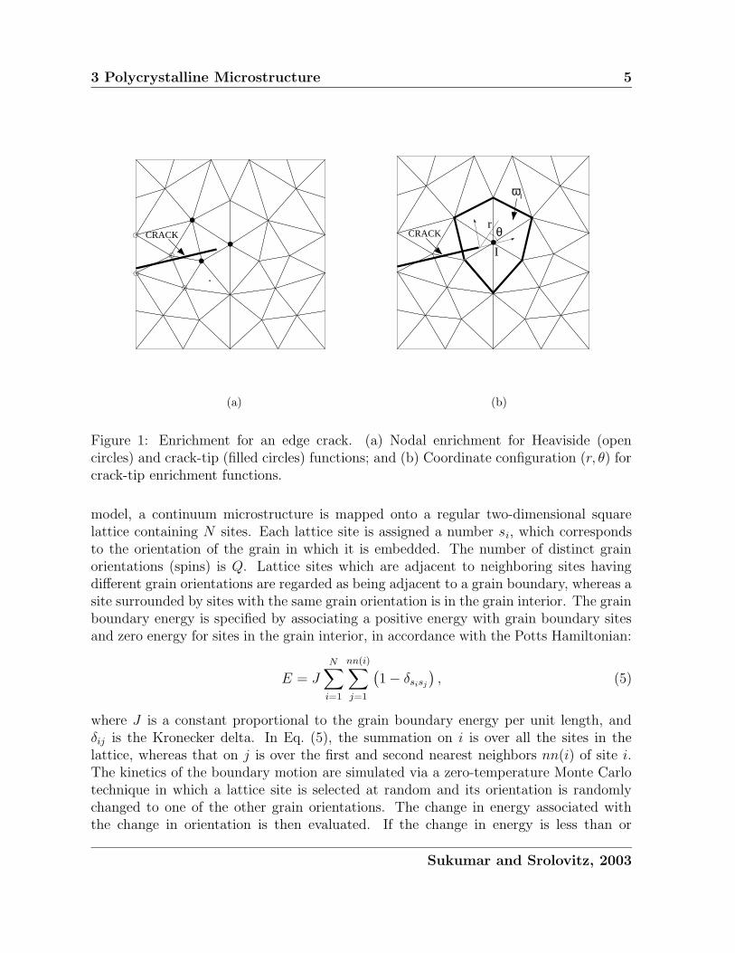
Four different meshes are considered: 10× 10, 20× 20, 40× 40, and 160× 160; a samplemesh (20×20 elements) is shown in Fig. 2a. To impose the essential boundary conditions,the crack is explicitly meshed over one element (AB), whereas the remaining part of thecrack (BC) is modeled by the X-FEM (Fig. 2a). The scaling factor rk = 4 is used inthe domain integral computations. The results of the convergence study are listed inTable 1 and in Fig. 2b, the relative error in the energy norm is plotted as a function ofthe mesh spacing he (log–log plot). In Fig. 2, the rate of convergence R is also indicated.The numerically computed SIFs are in agreement with the exact solution, and a rate ofconvergence of one-half is realized, which matches the theoretical convergence rate of thefinite element method in the presence of a dominant
√r-singularity [25].
Table 1: Convergence study: SIFs and relative error in the energy norm.
Mesh (he) KI KII
‖u− uh‖E(Ω)‖u‖E(Ω)
10× 10 (0.200) 1.006 1.006 9.379× 10⁻²
20× 20 (0.100) 1.003 1.003 6.945× 10⁻²
40× 40 (0.050) 1.002 1.002 5.018× 10⁻²
160× 160 (0.005) 1.000 1.000 2.549× 10⁻²
Sukumar and Srolovitz, 2003

5.2 Simulation Procedure 9
A B C
crack (FE mesh)
crack (X-FEM)
(a)
−5 −4 −3 −2 −1log (he)
−4
−3.5
−3
−2.5
−2
log
(Rel
ativ
e er
ror
in th
e en
ergy
nor
m)
R = 0.49
R1
(b)
Figure 2: Convergence study. (a) Mesh (20 × 20); and (b) Rate of convergence in theenergy norm.
5.2 Simulation Procedure
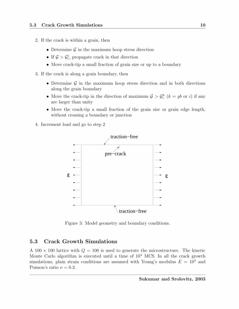
Polycrystalline microstructures are obtained using the Potts grain growth model outlinedin Section 3, and a grain boundary conforming finite element mesh of the microstructureis constructed. The problem domain is a square of edge length L. An initial pre-crackof size a (typically 0.02L) is introduced along a grain boundary that emanates fromx1 = 0.5L on the top surface. The top and bottom surfaces are traction-free; uniaxialstrain is applied in the x1-direction by fixing the left edge and imposing displacementboundary conditions on the right edge (Fig. 3).
Let us denote the critical fracture energy of a grain boundary by Ggbc and that of thegrain interior by Gic. The validity of Griffith-Irwin fracture mechanics is not lost at themicrostructural level [2], and hence one can use the classical notion of mechanical energyrelease rate G for crack growth. The energy release rate G under plane strain conditionsis related to the stress intensity factors through Irwin’s relation:
G =(1− ν2)(K2
I +K2II)
E. (12)
The crack will propagate along a grain boundary or through the grain interior dependingon which has the larger value of G/Gkc (k is either gb or i). In the grain interior, the crackis assumed to propagate preferentially in the the maximum hoop (circumferential) stressdirection (KII = 0) [34]. The crack growth procedure is summarized below:
1. Pre-crack the sample and apply load (strain-controlled)
Sukumar and Srolovitz, 2003
5.3 Crack Growth Simulations 10
2. If the crack is within a grain, then
• Determine G in the maximum hoop stress direction
• If G > Gic, propagate crack in that direction
• Move crack-tip a small fraction of grain size or up to a boundary
3. If the crack is along a grain boundary, then
• Determine G in the maximum hoop stress direction and in both directionsalong the grain boundary
• Move the crack-tip in the direction of maximum G > Gkc (k = gb or i) if anyare larger than unity
• Move the crack-tip a small fraction of the grain size or grain edge length,without crossing a boundary or junction
4. Increment load and go to step 2
traction−free
traction−free
ε ε
pre−crack
Figure 3: Model geometry and boundary conditions.
5.3 Crack Growth Simulations
A 100 × 100 lattice with Q = 100 is used to generate the microstructure. The kineticMonte Carlo algorithm is executed until a time of 104 MCS. In all the crack growthsimulations, plain strain conditions are assumed with Young’s modulus E = 105 andPoisson’s ratio ν = 0.3.
Sukumar and Srolovitz, 2003

6 Conclusions 11
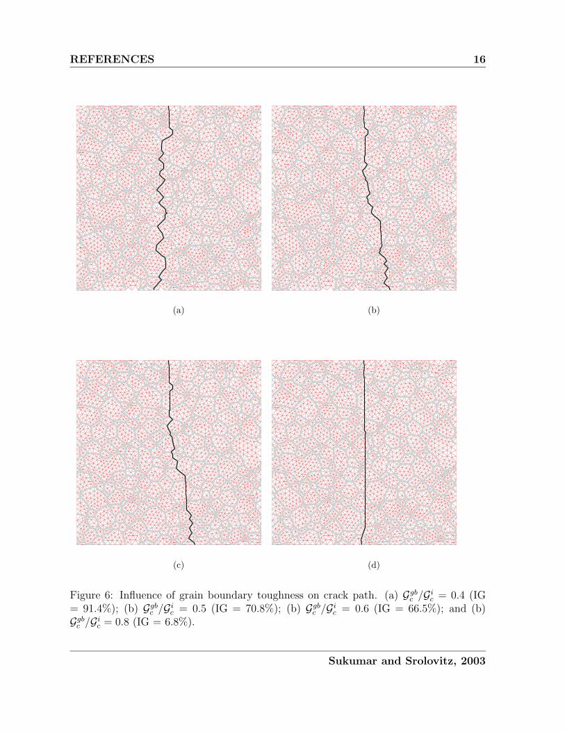
We first mesh a given microstructure using two different values of the length densityfunction ρ: with increasing ρ, smaller grains tend to be merged with larger grains. Toensure the presence of all the grains in the mesh, ρ should be selected to be a fractionof the average grain diameter d. Next, we study the influence of the mesh size on thecrack path. For a fixed ratio Ggbc /Gic = 0.4, we conducted crack growth simulations fordifferent values of ρ (Fig. 5). The results reveal that for ρ ≤ 0.03, there is little bias inthe crack path. Lastly, we present crack growth simulations using ρ = 0.03 for varyinggrain boundary toughness values: Ggbc /Gic = 0.4, 0.5, 0.6, 0.8. The simulation results areillustrated in Fig. 6 with the percentage of the crack path that is intergranular indicatedwithin braces. As the toughness of the grain boundary is increased, the crack path tendsto be transgranular-dominated; for Ggbc /Gic = 0.6, the crack path is mixed mode.
(a) (b)
Figure 4: Microstructure meshing. (a) ρ = 0.05; and (b) ρ = 0.02.
6 Conclusions
In this paper, we first established that the rate of convergence of the extended finite ele-ment method (X-FEM) for crack problems was one-half , which matches the theoreticalconvergence rate of the FEM in the presence of a dominant
√r-singularity [25]. Subse-
quently, through numerical simulations, we demonstrated the promise and potential ofthe X-FEM for crack growth studies in polycrystalline materials.
Sukumar and Srolovitz, 2003

REFERENCES 12
Acknowledgments
The authors thank Dr. Timothy Baker for developing the microstructural meshing algo-rithm and Professor Mark Miodownik for providing the code for the Potts grain growthmodel. Helpful discussions with Professor Jean Prevost are also acknowledged.
References
[1] A. G. Evans and K. T. Faber. The crack growth resistance of microcracking brittlematerials. Journal of the American Ceramic Society, 67(4):255–260, 1984.
[2] B. Lawn. Fracture of Brittle Solids. Cambridge University Press, Cambridge, Eng-land, second edition, 1993.
[3] T. Watanabe. The impact of grain boundary character distribution on fracture inpolycrystals. Materials Science and Engineering A, 176:39–49, 1994.
[4] M. Kumar, W. E. King, and A. J. Schwartz. Modifications to the microstructuraltopology in f.c.c. materials through thermomechanical processing. Acta Materialia,48(9):2081–2091, 2000.
[5] C. A. Schuh, M. Kumar, and W. E. King. Analysis of grain boundary networks andtheir evolution during grain boundary engineering. Acta Materialia, 51(3):687–700,2003.
[6] P. D. Beale and D. J. Srolovitz. Elastic fracture in random materials. PhysicalReview B, 37(10):5500–5507, 1988.
[7] W. A. Curtin and H. Scher. Brittle fracture of disordered materials. Journal ofMaterials Research, 5(3):535–553, 1990.
[8] H. J. Herrmann and S. Roux, editors. Statistical Models for the Fracture of Disor-dered Media. North-Holland, Amsterdam, The Netherlands, 1990.
[9] W. H. Yang, D. J. Srolovitz, G. N. Hassold, and M. P. Anderson. Microstructuraleffects in the fracture of brittle materials. In M. P. Anderson and A. D. Rollett,editors, Simulation and Theory of Evolving Microstructures, pages 277–284, TheMetallurgical Society, Warrendale, PA, 1990.
[10] J. E. Bolander, Jr and S. Saito. Fracture analyses using spring networks with randomgeometry. Engineering Fracture Mechanics, 61:569–591, 1998.
[11] S. Ghosh, K. Lee, and P. Raghavan. A multi-level computational model for multi-scale damage analysis in composite and porous materials. International Journal ofSolids and Structures, 38:2335–2385, 2001.
Sukumar and Srolovitz, 2003

REFERENCES 13
[12] P. D. Zavattieri and H. D. Espinosa. Grain level analysis of crack initiation andpropagation in brittle materials. Acta Materialia, 49:4291–4311, 2001.
[13] W. A. Curtin. Size scaling of strength in heterogeneous materials. Physical ReviewLetters, 80(7):1445–1448, 1998.
[14] A. Jagota and S. J. Bennison. Spring-network and finite-element models for elas-ticity and fracture. In K. K. Bardhan, B. K. Chakrabarti, and A. Hansen, editors,Nonlinearity and Breakdown in Soft Condensed Matter. (Springer Lecture Notes inPhysics 437), pages 186–201, Springer, Berlin, 1994.
[15] L. F. Martha, P. A. Wawrzynek, and A. R. Ingraffea. Arbitrary crack representationusing solid modeling. Engineering with Computers, 9:63–82, 1993.
[16] J. B. C. Neto, P. A. Wawrzynek, M. T. M. Carvalho, L. F. Martha, and A. R.Ingraffea. An algorithm for three-dimensional mesh generation for arbitrary regionswith cracks. Engineering with Computers, 17:75–91, 2001.
[17] N. Moes, J. Dolbow, and T. Belytschko. A finite element method for crack growthwithout remeshing. International Journal for Numerical Methods in Engineering,46(1):131–150, 1999.
[18] C. Daux, N. Moes, J. Dolbow, N. Sukumar, and T. Belytschko. Arbitrary cracks andholes with the extended finite element method. International Journal for NumericalMethods in Engineering, 48(12):1741–1760, 2000.
[19] J. M. Melenk and I. Babuska. The partition of unity finite element method: Basictheory and applications. Computer Methods in Applied Mechanics and Engineering,139:289–314, 1996.
[20] J. C. Simo, J. Oliver, and F. Armero. An analysis of strong discontinuities inducedby strain softening in rate-independent inelastis solids. Computational Mechanics,12:277–296, 1993.
[21] A. M. Stoneham and J. H. Harding. Not too big, not too small: The appropriatescale. Nature Materials, 2(2):77–83, 2003.
[22] N. Sukumar, D. J. Srolovitz, T. J. Baker, and J.-H. Prevost. Brittle fracture in poly-crystalline microstructures with the extended finite element method. InternationalJournal for Numerical Methods in Engineering, 56(14):2015–2037, 2003.
[23] T. Strouboulis, K. Copps, and I. Babuska. The generalized finite element method.Computer Methods in Applied Mechanics and Engineering, 190(32–33):4081–4193,2001.
Sukumar and Srolovitz, 2003

REFERENCES 14
[24] C. A. Duarte, O. N. Hamzeh, T. J. Liszka, and W. W. Tworzydlo. The elementpartition method for the simulation of three-dimensional dynamic crack propagation.Computer Methods in Applied Mechanics and Engineering, 119(15–17):2227–2262,2001.
[25] G. Strang and G. Fix. An Analysis of the Finite Element Method. Prentice-Hall,Englewood Cliffs, N.J., 1973.
[26] N. Sukumar, Z. Huang, J.-H. Prevost, and Z. Suo. Partition of unity enrichmentfor bimaterial interface cracks. International Journal for Numerical Methods inEngineering, June 2003. accepted for publication.
[27] N. Sukumar and J.-H. Prevost. Modeling quasi-static crack growth with the extendedfinite element method. Part I: Computer implementation. International Journal ofSolids and Structures, June 2003. revised submission.
[28] D. J. Srolovitz, M. P. Anderson, G. S. Grest, and P. S. Sahni. Grain growth in twodimensions. Scripta Metallurgica, 17:241–246, 1983.
[29] W. C. Carter, S. A. Langer, and E. R. Fuller, Jr. Object-Oriented Finite ElementAnalysis (OOF). Available at http://www.ctcms.nist.gov/oof, National Institutefor Standards and Technology, Gaithersburg, MD, 1998.
[30] S. Ghosh and S. N. Mukhopadhyay. A material based finite-element analysis ofheterogeneous media involving Dirichlet tessellations. Computer Methods in AppliedMechanics and Engineering, 104(2):211–247, 1993.
[31] T. J. Baker. Triangulations, mesh generation and point placement strategies. InD. A. Caughey and M. M. Hafez, editors, Frontiers of Computational Fluid Dynam-ics, pages 101–115, New York, NY, 1994. John Wiley & Sons.
[32] B. Moran and C. F. Shih. Crack tip and associated domain integrals from momentumand energy balance. Engineering Fracture Mechanics, 27(6):615–641, 1987.
[33] J. F. Yau, S. S. Wang, and H. T. Corten. A mixed-mode crack analysis of isotropicsolids using conservation laws of elasticity. Journal of Applied Mechanics, 47:335–341, 1980.
[34] F. Erdogan and G. C. Sih. On the crack extension in plates under plane loading andtransverse shear. Journal of Basic Engineering, 85:519–527, 1963.
Sukumar and Srolovitz, 2003

REFERENCES 15
(a) (b)
(c)
Figure 5: Mesh size sensitivity on crack path for Ggbc /Gic = 0.4. (a) ρ = 0.04; (b) ρ = 0.03;and (c) ρ = 0.015.
Sukumar and Srolovitz, 2003
REFERENCES 16
(a) (b)
(c) (d)
Figure 6: Influence of grain boundary toughness on crack path. (a) Ggbc /Gic = 0.4 (IG= 91.4%); (b) Ggbc /Gic = 0.5 (IG = 70.8%); (b) Ggbc /Gic = 0.6 (IG = 66.5%); and (b)Ggbc /Gic = 0.8 (IG = 6.8%).
Sukumar and Srolovitz, 2003