Embed Size (px)
Citation preview

118
TECHNISCHE MECHANIK, 32, 2-5, 2012, 118-129 submitted: October 15, 2011
Cleavage Crack Propagation Characterization in a Nuclear Pressure Vessel Steel A. Bousquet, S. Marie, P. Bompard This study deals with physical mechanisms of cleavage cracks and criteria related to brittle fracture. This work tends to put a slant on scientific tools and methodologies to improve the propagation and crack arrest topic. Experiments and Scanning Electron Microscope fracture surface analyses were carried out on Compact Tension specimens made of 16MND5 steel. The eXtended Finite Element Method (X-FEM) is used in CAST3M finite element analysis software to model crack propagation. Numerical computations combine a local non linear dynamic approach and a fracture criterion based on critical cleavage stress. The links of the criterion with temperature and strain rate are depicted in order to get a robust physical model which can be effective for model-based predictions of industrial structures. 1 Introduction In the frame of the safety demonstration of nuclear key components, the initiation stage of cracks is considered as an important issue. For the justification of the service time extension of nuclear power stations up to sixty years, it is necessary to bring new elements to the nuclear vessel integrity analysis. Analyzing the stability of a defect during sudden loading, such as cold thermal shock, is fundamental in structure integrity analyses. Component integrity analyses mainly consider initiation criteria. Nevertheless, in the frame of the extension of the nominal service life of structures, the possibility of crack propagation and arrest after its initiation is investigated. In the case of the Loss-Of-Coolant Accident (L.O.C.A.) in a nuclear power plant, the arrest emergency procedure consists of decreasing the reactor core pressure and injecting water at around 10°C in the reactor core. The temperature of the inner wall decreases from 300°C to room temperature. Thus, a thermal gradient in the vessel thick can induce a crack initiation because of a tension loading in the inner wall of the vessel. In such cases, study of crack propagation and arrest is a counterpart of crack initiation analysis in order to catch phenomena involved in cleavage fracture. In order to initiate and propagate a crack in a structure, stresses and strains in the vicinity of the crack tip have to be high enough to separate the material. According to standards, the flaw assessment analysis is based on a global approach to fracture. Under linear elastic conditions (LEFM), the Stress Intensity Factor (SIF) provides a single parameter that describes the stress and strain fields in the vicinity of the crack tip and outside the crack tip plastic zone. The global approach to fracture consists of comparing the SIF and the isothermal fracture toughness of the material. According to the nuclear standards (RCCM, 2002), a crack will initiate when the applied SIF equals the critical value of the material K JC. The dynamic effects involved in unstable cleavage crack propagation are important. Some studies (Kalthoff et al., 1977; Kalthoff et al., 1980) quantify dynamic effects in typical fracture specimen geometries during dynamic crack propagation and arrest. The authors point out the difference between the true dynamic SIF compared to the SIF determined from a static analysis. The dynamic SIF fall below the statically calculated value after initiation of the crack because of the conversion of stored elastic energy into kinetic energy within the specimen. Later, the dynamic SIF exceeded the static value as kinetic energy is converted into strain energy. Besides, significant oscillations of the SIF were observed after crack arrest which damped out with time. Dynamic approaches show that inertial effects are important to properly depict the dynamic crack propagation, arrest and possible reinitiating events in specimens of finite geometry (Hahn et al., 1973; Kanninen et al., 1990). Moreover, the transfer of fracture toughness results from laboratory specimens to structural components is difficult to ensure because fracture toughness depends on the specimen geometry, the mechanical behavior of the material and the loading path. As an alternative, the local approach to fracture is considered to have a better description of the mechanical fields close to the crack tip. One of the first precursory models of this local approach to cleavage fracture is the model made by Ritchie, Knott and Rice, or RKR model, to identify the initiation phase of cleavage (Ritchie et al., 1973). The main step of brittle fracture is the achievement of a critical stress σc which is evaluated to the maximal principal stress at a given distance λc from the crack tip (Figure 1). This distance from the crack tip is

119
linked to the material microstructure without prejudging the form or the singularity of the mechanical fields. Since then, probabilistic models, based on a local approach to fracture and microstructural defect statistics, have been established such as the Beremin model (Beremin, 1983).
Figure 1. RKR model
Irwin introduced the crack arrest toughness concept K Ia (Irwin et Wells, 1965). There is crack arrest when the the SIF is below or equal to K Ia. Nevertheless, the procedure ASTM E1221 (ASTM E1221, 2010), used to determine KIa, is based on a static approach which is debatable because the dynamic effects of a propagating crack are not taken into account. This study, following former works (Prabel et al., 2008; Berdin et al., 2008), deals with physical micromechanisms and criterion related to cleavage propagation and arrest.
The Section 2 describes the material used in this study, its microstructure and its characterization at high strain rate. The supporting experiments are also presented including a description of the measuring tools and the results of fracture tests on Compact Tension (CT) specimens. Scanning Electron Microscope (SEM) fracture surface analyses were carried out to catch physical micromechanisms of cleavage crack propagation and arrest. The Section 3 is devoted to the numerical tools used in the finite element analysis software CAST3M (www.cast3m.cea.fr, 2011) and to identify a crack propagation criterion thanks to numerical computations of Compact Tension specimens with crack speed imposed equal to experimental measurements. The purpose is then to confirm the validity of the critical stress criterion on different specimen geometries and loading paths. Eventually, summary and discussion are given in the Section 4. 2 Experimental Campaign 2.1 Description of the Material A 16MND5 (A508) grade ferritic steel, taken from a French Pressurized Water Reactor (PWR) vessel ring blank, is used in the experimental campaign. Its chemical composition is given in Figure 2. Quasi-static tensile tests were made for a range of temperature from -175°C to 25°C (Chapuliot et al., 2005). The yield stress increases with decreasing temperature and rising loading rate. A power-type law (1) describes very well the tensile curve of the material at any intermediate temperature (Figure 3).
ε = + ε + +
where εtot is the total strain, σeq is the equivalent stress, E is the Young modulus, ε0, E’, σY’, K and n are coefficients. E, σY, ε0, E’, σY’, K and n are temperature dependant values. Experiments were carried out considering Compact Tension cracked specimens so as to study cleavage crack initiation, propagation and arrest. The effects of stress triaxiality, Warm Pre-Stressing (WPS) and thermal shock loading were investigated on this material in former works (Chapuliot et al., 2005; Reytier et al., 2006a,b). Even though ample data are available for the aforementioned material, the effect of strain rate remains to be determined in order to better understand the response of the material under dynamic loading.
Figure 2. Chemical composition of the 16MND5 (A508) material.
σI (r = λc ) = σc
if <
if ≥ (1) [10]

120
Figure 3. Comparison of fitted tensile curves (lines) and experimental curves (points) at different temperatures
(Chapuliot et al., 2005). 2.2 Characterization of the Material Dynamic Behavior
High strain rate material behavior can be described by an additive law, which adds a viscosity stress to the static stress, or by a multiplicative law, which multiplies the static stress by a factor depending on the strain rate. The high strain rate behavior of the 16MND5 steel has been previously studied by Prabel, Rossol and Tanguy (Prabel et al., 2008; Rossoll, 1993; Tanguy, 2001). Rossol (Rossoll, 1993) made a dynamic characterization of the material for a range of strain rate from 10 -3 s-1 to 5,5 s-1 at 20°C. The formulation of the elastic-viscoplastic Cowper-Symonds law is given by the equation (2). σ (ε , ε̇, T) = σ (ε , T) 1 + ̇ where εin is the inelastic strain and T is the temperature. The equation (2) links the dynamic equivalent stress σeq to its static value σstat via a coefficient depending on the equivalent strain rate ε̇. This original Cowper-Symonds law is a multiplicative law with two parameters D and p. These coefficients, identified by Rossoll, are D = 10 8s-1 and p = 12. In our study, experiments were made with the Split-Hopkinson Pressure Bar for a range of strain rate from 10 2 to 104 s-1 and for seven temperatures from -175°C to 25°C. The Split-Hopkinson Pressure Bar is an apparatus for testing the dynamic stress-strain response of materials. The specimen is placed between two straight bars, called the incident bar and the transmission bar (Figure 4). A striker bar is responsible for a compressive elastic longitudinal stress wave which propagates through the bar toward the specimen. Two strain gages are in the middle of the bars. Then using the unidimensional equation of the elastic wave to the bars, the dynamic stress-strain response of the material can be deduced.
Figure 4. The Split-Hopkinson Pressure Bar apparatus
(2)
Stress (MPa)
Plastic strain (%)
-175°C
-150°C
-145°C -125°C -100°C
-75°C -50°C -20°C 25°C

121
Figure 5. Variation of true stress with respect to strain rate for three temperatures at 10% of total strain. Figure 5 represents the variation of true stress with respect to strain rate for three different temperatures at 10% of total strain. The true stress increases as temperature decreases and as strain rate increases. On one hand, getting the same set of parameters (D, p) for seven temperatures is difficult. On the other hand, it was observed that plastic yielding of the material led to adiabatic heating and to softening of the material. This effect of thermal softening reduces strain hardening which is delicate to reproduce by the elastic-viscoplastic law. In order to better represent the heating effects, the set of parameters (D, p) was identified at different temperatures (Figure 6). Figure 6. Set of parameters (D, p) at five temperatures Predictions based by this modified Cowper-Symonds elastic-viscoplastic law are in good agreement with experimental results (Figure 7).
Figure 7. Comparison of predictions made by the modified Cowper-Symonds law with experimental results for different strain rates at -150°C. 2.3 Cleavage Fracture Tests Fracture experiments were made on Compact Tension (CT) specimens respecting the ASTM E1820 standard (ASTM E1820, 1986). The thickness of the CT is either 25 mm or reduced to 15, 10, and 5 mm in order to promote a straight crack front during cleavage propagation. There is no lateral notch on the CT because of the crack advance measuring system which needs to be stuck on the surfaces of the specimen. These specimens were pre-cracked by fatigue loading using the conventional decreasing ΔK procedure (ASTM E1820, 1986). The
plastic strain (%)
stress (MPa)
Re

122
Compact Tension specimen geometry is described in Figure 8, with two kinds of crack path that have been observed in the experimental campaign, that is to say straight crack and branching cracks. The fracture tests were made at -150°C, -125°C, -100°C, -75°C and -50°C in order to catch physical phenomena occurring during crack propagation. It has to be noticed that the reference temperature of the Master Curves for this material is -120.5°C. The specimens are placed in a thermal vessel, and the temperature is controlled by introducing liquid nitrogen. Because of the tested temperatures, there is some icing in the thermal vessel. Hence, it was not possible at that time to use an optical device under these experimental conditions to measure the crack propagation. Crack gages, made of filaments, were stuck on both sides of the CT specimen. Two kinds of crack gages were used with different gaps between each filament. The recording of gage signals is triggered by means of a filament cutting. When a filament breaks, the overall resistance of the gage increases and the potential difference increases by stages. A computer with fast acquisition cards is used to record the signal from the crack gages. The quality of the experimental results is checked by analysing the correlation between the crack speeds given by the crack gage signals placed on each side of the specimen. In order to confirm the validity of our experimental results and thanks to improvements on the experimental device, the use of a high speed framing camera system has been made possible to determine the crack front advancement. The observed side of the CT specimen is polished, and there is a crack gage on the side which is not recorded. The time resolution of this system is 2 µs. We made a comparison of these two measuring systems. Figure 9 shows a comparison of the crack speeds given by a crack gage and the high speed framing camera system for a Compact Tension specimen tested at -150°C with a straight crack.
Figure 8. Geometry of Compact Tension specimen (a); Straight crack path (b); Branching crack path (c).
Figure 9. Comparison of crack speeds measured by a crack gage and the high speed framing camera system for an experiment on CT specimen at -150°C.
2.4 Experimental Results
Among the fracture tests, two kinds of crack path have been observed (Figure 8b, 8c). The crack path is not always in the symmetry plane of the specimen (Figure 8c). The initiation of cleavage crack can be made in two different planes with an angle in a range from 20° to 45°. In some cases, the two created branches rejoin in the
(a) (b) (c)

123
symmetry plane, but in other cases, one of the branches arrests before the end of the specimen and the other one goes through the CT. As there is no lateral notch on the specimen, the fracture symmetry plane can not be privileged. Besides, plastic yielding in the crack tip is much more important due to the small thickness of the specimens. Branching cracks appear for high loading that increases the effect of plastic zones. We can observe that branching cracks are following the plastic wings. A huge difference of fracture time is observed between straight or branching cracks according to the Force - Crack Mouth Opening Displacement curves. This discrepancy is confirmed by the calculation of the J parameter at crack initiation, translated into elastic-plastic SIF, named KJ (Figure 10a). The formulation of K J (4) assumes a plane strain condition which is debatable in our case due to small thickness of the CT specimens. This trend is confirmed by numerical results because plane stress computations have given better Force - Crack Mouth Opening Displacement curves than plane strain simulations.
K = J. E∗ (4) with E∗ =
According to Figure 10a, the energy stored in the specimen is higher for a branching crack path. Plastic wings, obtained by mechanical loading, has an influence on the orientation of the crack path. Moreover, there is a correlation between the fracture surface observed with a SEM and the amount of energy available in the specimen at the initiation time (section 2.5).
Figure 10. Variation of fracture toughness with respect to crack path at -125°C (a); Variation of fracture toughness for straight crack path with respect to temperature (b).
Temperature has an important impact on the fracture mechanism. Figure 10b, depicting straight crack experiments, logically shows a huge increase of the fracture toughness when the temperature goes from -150°C to -100°C. Figure 11 shows the crack speed variation for specimens that are encircled in Figure 10b. The crack speed trends are similar, according to Figure 11, for two specimens with equivalent fracture toughness at -125°C and -150°C (Figure 10b). Hence, the higher the fracture toughness is, higher is the energy available to cleave and faster propagates the crack. This fact reveals that the crack speed is an increasing function of the energy available in the specimen to cleave. A similar trend has already been reported in former studies (Kalthoff, 1985; Zehnder, 1990).
b
under plane strain condition
a
124
Figure 11. Variation of crack speeds with respect to crack advance for specimens encircled in Figure 10b.
According to Figure 11, three main stages can be discerned. The initial crack speed is around 1100 m.s -1 before quickly decreasing until propagation at a constant speed. Then, after 15 mm of propagation, there is a deceleration before crack arrest.
2.5 Fracture Surface Analyses
The fracture surfaces were observed by a Scanning Electron Microscope (SEM) and an optical microscope to examine physical micromechanisms which are involved during initiation, propagation and arrest of cleavage cracks. The purpose is to identify the possible dependencies of fracture micromechanisms on temperature and strain rate and to evaluate consequences on the chosen macroscopic criterion.
From -150°C to -100°C, the specimens have an initiation zone with few initiation sites placed at around 100 µm from the fatigue pre-crack. At -150°C and -125°C, the specimens with straight or branching crack paths have a typical cleavage fracture surface including some shearing zones with high plastic strain at the end of the crack path. Indeed, the available energy to cleave at the end of propagation is smaller, and the crack chooses the most easily dissociated cleavage planes to propagate. That is why the fracture surface is lightly disturbed at the end of CT specimens. On the contrary, at -100°C, -75°C and -50°C, the specimens have been fractured by cleavage, but the fracture surface relief is much more accentuated (Figure 12a., 12b). Besides, much more shearing zones can be observed on the crack propagation path at these temperatures (Figure 12c, 12d). This means a more significant plastic behaviour occurs during phenomena of cleavage at these temperatures.
Figure 12. Fracture surface of a Compact Tension specimen tested at -100°C with a straight crack path observed by an optical microscope (a); Fracture surface of the propagation phase observed by SEM (b, c, d).
Fatigue pre-crack
Propagation way
a b c d
Shearing zone
KJ = 292 MPa.m0.5
KJ = 41 MPa.m0.5
KJ = 42 MPa.m0.5

125
3 Modelling
3.1 Numerical Method: the eXtended Finite Element Method Many finite element modelling techniques are available to simulate macroscopic crack propagation. In this work, the eXtended Finite Element Method (X-FEM), based on partition of unity (Babuska et al., 1997), is used in CAST3M [20] finite element analysis software to model crack propagation (Prabel et al., 2007; Prabel et al., 2008; Simatos et al., 2010). Concerning the crack description, this methodology offers freedom from the meshing of the structure as the crack is described implicitly by a pair of level-set functions ( ψ, Ф). Their iso-zero determines the crack plane and the crack front, as shown in Figure 13a. When a crack propagates, the values of these functions need to be updated. Hence, the evolution of level set functions reflects the progression of the crack front. Information about the crack position is then used to improve the approximation of the displacement field. Displacement in the element is then expressed by the relation (5). We add to the standard finite element approximation, including the usual shape functions N, a discontinuous enrichment with the jump function H and a singular enrichment by means of functions Fj. The enrichment strategy (Figure 13b) consists of enriching the displacement field for elements cut by the crack. When the crack totally cut an element, the nodes are enriched with the jump function H and the nodes, belonging to an element with the crack tip, are enriched by means of singular functions Fj. Figure 13. Description of the crack front by means of level set functions ( ψ, Ф) (a); Enrichment strategy (b).
with : displacement vector; and
Finite element modelling is performed in order to obtain an accurate description of the mechanical fields ahead of the crack tip. The finite element code used for the computations is the CAST3M code (www.cast3m.cea.fr, 2011). 2D mechanical analyses were performed under plane strain condition in large deformations. Only a half of the specimen is modelled because of the symmetry in the loading and in the specimen shape. The mesh is made of 4618 linear elements. Along the crack path, the element size is 100 µm. Figure 14 shows the applied boundary conditions and the location of loaded line for the finite element computations. The Y nodal displacement of the crack ligament is locked to take symmetry into account. The experimental stiffness of the machine and the assembly is modelled with an elastic bar.
(5)
b a

126
Figure 14. Mesh and loading conditions of a CT specimen
3.2 Identification of the Crack Propagation Criterion
Fracture surface analyses have shown that the main fracture mechanism is cleavage in the experimental campaign. The separation of cleavage planes is controlled by the level of loading ahead of the crack tip. That is why a local approach to fracture is much more reliable to describe cleavage crack propagation. To model the propagation of a cleavage crack, we choose a local stress criterion based on the RKR criterion (Prabel et al., 2008). Brittle fracture appears when the maximum principal stress reaches a critical value at 100 µm from the crack tip according to the SEM fracture surface analyses. This critical distance from the crack tip is both close to the distance from microstructural cleavage initiation sites to the fatigue pre-crack (section 2.5) and preserve a relatively good numerical quality. 2D mechanical analyses have been made under plane strain condition for Compact Tension specimens by directly applying the time variation of the crack length as it was measured in the experiments. After a quasi-static loading which leads to the initiation phase of the crack (determined from fracture toughness found in experiments), crack propagation occurs dynamically with the modified Cowper-Symonds elastic-viscoplastic law.
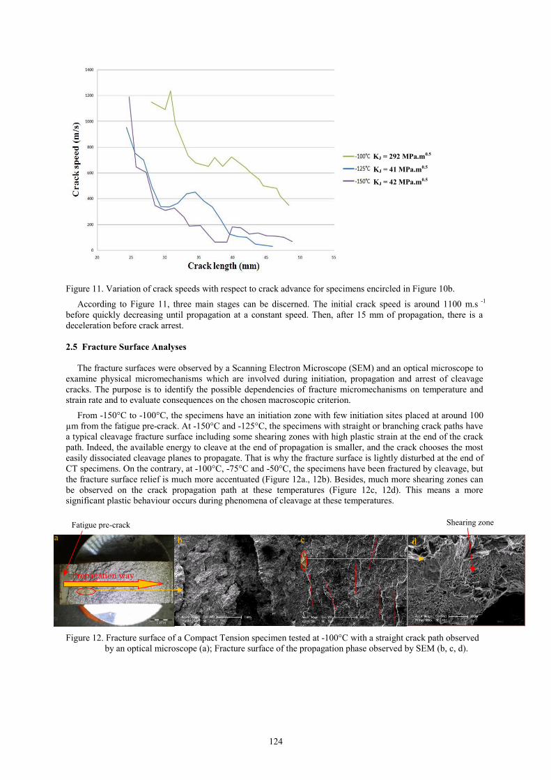
Figure 15 shows the variation of the stress calculated by the RKR criterion with respect to the equivalent plastic strain rate for CT specimens tested at -125°C. The way to calculate the stress criterion consists of averaging the maximum principal stress over a square zone (50 µm long on each side) centred around 100 µm from the crack tip. This variation is used as a predictive criterion for crack propagation and arrest. This critical stress criterion is coherent with the usual critical stress given in the literature for the initiation cleavage stress which is estimated to 1450 MPa for a strain rate equal to zero (Chapuliot et al., 2008; Niclaeys et al., 2011). This dependence of stress on strain rate has to be clarified since a constant critical stress is generally assumed in the literature (Berdin et al., 2008). Figure 15 puts also a slant on the similar trend of critical stress and yield stress with respect to plastic strain rate. To justify the increase of the critical stress with respect to the plastic strain rate, it is possible to propose a few assumptions:
- a first assumption is that during the propagation, it is necessary to reach a minimum plastic strain to initiate cleavage from particles above the crack front. As strain rate increases during the propagation, the stress, corresponding to this minimum plastic strain, increases due to the viscosity of the material,
- another assumption is that during the propagation, ductile ligaments could exist behind the crack front (Hoagland et al., 1971; Rosenfield and Majumdar, 1986). The increase of the stress could also be explained by the viscosity effect on the related fracture strain of the ligament.
Further investigations on the physical mechanisms will be made in the frame of the project.
Y
X
127
Figure 15. Variation of the critical stress criterion with respect to the equivalent plastic strain rate at -125°C for a 2D plane strain modelling.
4 Summary In order to characterize dynamic propagation and arrest of cleavage cracks in a nuclear PWR vessel steel in the continuity of former work (Prabel et al., 2008), experiments and simulations with X-FEM were carried out on thin Compact Tension specimens in mode I. Fracture surface analyses, made with Scanning Electron Microscope, have shown a cleavage mechanism involved in the fracture of a 16MND5 (A508) nuclear steel. Shearing zones with local ductile damages have been observed between different cleavage planes in the crack path. We have chosen a critical stress criterion at the crack tip based on the RKR model (Prabel et al., 2008). A crack propagation model using the same kind of criterion has already given efficient predictions for rings with an isothermal mechanical loading in mixed mode (Prabel et al., 2008). Then, the next step of this work will focus on the identification of the criterion dependencies on strain rate from -150°C to -50°C by a 3D modelling in order to study the effect of temperature. At this stage, further investigations will have been made to justify the variation of the critical stress with respect to the plastic strain rate. Then, to evaluate the efficiency of our propagation model, we will have to make predictive analyses on different experiments. It is also necessary to study in details the crack branching phenomena observed with the high-speed framing camera system. Acknowledgements The authors would like to thank the CEA for his financial support and Ecole Centrale Paris for SEM analyses. References American Society for Testing and Material - Standard Test Method for Determining Plane-Strain Crack-Arrest Fracture Toughness, KIa, of Ferritic Steels, ASTM E1221, (2010).
American Society for Testing and Material A2 - special requirements for testing compact specimen, ASTME 1820, (1986).
Babuska, I.; Melenk, J.M.: The partition of unity method. International Journal of Numerical Method Engineering, 40, (1997), 727-758.
Berdin, C.; Hajjaj, M.; Bompard, P.; Bugat, S.: Local approach to fracture for cleavage crack arrest prediction. Engineering Fracture Mechanics, 75, (2008), 3264-3275.

128
Beremin, F.M.: A local criterion for cleavage fracture of a nuclear pressure vessel steel. Metallurgical transactions, 14, (1983), 2277-2287.
Cast3M: Finite Element software developed by the French Atomic Energy Commission, http://www-cast3m.cea.fr, (2011). Chapuliot, S.; Lacire, M.H.; Marie, S.; Nédélec, M.: Thermomechanical analysis of thermal shock fracture in the brittle/ductile transition zone - Part I: Description of the tests. Engineering Fracture Mechanics, 72, (2005), 661-673. Chapuliot, S.; Le Corre, V.: A simplified expression for low cleavage probability calculation. Engineering Fracture Mechanics, 75, (2008), 1488-1506. Hahn, G.T.; Hoagland, R.G.; Kanninen, M.F.; Rosenfield, A.R.: A preliminary study of fast fracture and arrest in DCB test specimen. Proceedings of the conference on dynamic crack propagation , Leyden, The Netherlands, (1973), 649-662. Hoagland, R. G.; Rosenfield, A. R.; Hahn G. T.: Mechanisms of fast fracture and arrest in steels. Metallurgical and Materials Transactions B, 3, (1971), 123-136. Irwin, G.R.; Wells, A.A.: A continuum mechanics view of crack propagation, Metallurgical Review, (1965), 223-270. Kalthoff, J.F.; Beinert, J.; Winkler, S.: Measurements of dynamic stress intensity factors for fast running and arresting cracks in double-cantilever-beam specimens. Fast Fracture and Crack Arrest, ASTM STP 627, G.T. Hahn and M.F.Kanninen Eds., American Society for Testing and Materials , (1977), 161-176. Kalthoff, J.F.; Beinert, J.; Winkler, S.; Klemm, W.: Experimental analysis of dynamic effects in different crack arrest test specimens. Crack Arrest Methodology and Applications, ASTM STP 711, American Society for Testing and Materials, (1980), 109-127. Kalthoff, J.F.: On the measurement of dynamic fracture toughness: a review of recent work. International Journal of Fracture, 27, (1985), 277-298. Kanninen, M.F.; Hudak, S.J.; Couque, H.R.; Dexter, R.J.; O’Donoghue, P.E.: Viscoplastic-dynamic crack propagation: experimental and analysis research for crack arrest applications in engineering structures. International Journal of Fracture , 42, (1990), 239-260. Niclaeys, C.; N’Guyen, T.H.; Marie, S.; Chapuliot, S.; Degallaix, S.; Non fracture prediction of a C-MN weld joint in brittle to ductile transition temperature range - Part I : Experimental results and numerical study. Paper submitted to Engineering Fracture Mechanics . Prabel, B.; Marie, S.; Combescure, A.: Using the X-FEM method to model the dynamic propagation and arrest of cleavage cracks in ferritic steel. Engineering Fracture Mechanics, 75, (2008), 2984-3009. Prabel, B.; Combescure, A.; Gravouil, A.; Marie, S.: Level set non-matching meshes: Application to dynamic crack propagation in elastic-plastic media. International Journal of Numerical Methods in Engineering , 69, (2007), 1553-1569. RCCM, Annexe A16 – Tome I – Vol. Z, RCC-M, AFCEN, (2002). Reytier, M.; Chapuliot, S.; Marie, S.; Nédélec, M.: Thermomechanical analysis of thermal shock fracture in the brittle/ductile transition zone - Part II: Numerical calculations and interpretation of the test results. Engineering Fracture Mechanics, 73, (2006a), 283-295. Reytier, M.; Chapuliot, S.; Marie, S.; Ferry, L.; Nédélec, M.: Study of cleavage initiation under thermal shock by tests on cracked rings and thermomechanical calculations. Nuclear Engineering Design, 236, (2006b), 1039-1050.

129
Ritchie, R.O.; Knott, J.F.; Rice, J.: On the relationship between critical tensile stress and fracture stress in mild steels. Journal of Mechanics and Physics of Solids , 21, (1973), 395-410. Rosenfield, A. R.; Majumdar, B. S.: A micromechanical model for cleavage-crack reinitiation. Metallurgical and Materials Transactions A, 22, (1986), 1053-1059. Rossoll, A.: Local approach of ductile cast iron fracture toughness measured by Charpy test. PhD, Ecole Centrale Paris, (1993). Simatos, A.; Marie, S.; Combescure, A.; Cazes, F.: Modelling ductile tearing from diffuse plasticity to crack propagation. ASME PVP, Washington, USA, (2010). Tanguy, B.: Modélisation de l’essai Charpy par l’approche locale de la rupture: application au cas de l’acier 16MND5 dans le domaine de transition. PhD, Ecole des Mines de Paris, (2001). Zehnder, A.T.; Rosakis, A.J.: Dynamic fracture initiation and propagation in 4340 steel under impact loading. International Journal of Fracture , 43, (1990), 271-285. _________________________________________________________________________________________ Address: Ph.D Student-Ing. Amaury Bousquet 1,2, Dr.-Ing. Stéphane Marie1 and Prof. Dr.-Ing. Philippe Bompard2, 1CEA, DEN, DM2S, SEMT, LISN, CEA-Saclay, F-91191 Gif-sur-Yvette, FRANCE. 2Mechanics, Structures and Materials Laboratory, CNRS UMR 8579, Ecole Centrale Paris, Grande Voie des Vignes, 92295 Châtenay-Malabry, FRANCE. email: [email protected] ; [email protected] ; [email protected] .