Embed Size (px)
Citation preview
1
Finite element analysis of ion-implanted diamond surface swelling
Federico Bosia a,f§
, Silvia Calusib, Lorenzo Giuntini
c, Stefano Lagomarsino
d, Alessandro Lo
Giudiceb,f
, Mirko Massic, Paolo Olivero
b,f, Federico Picollo
b,f, Silvio Sciortino
e, Andrea
Sordinid, Maurizio Vannoni
d, Ettore Vittone
b,f
a Department of Theoretical Physics, University of Torino, Italy
b Department of Experimental Physics and , University of
Torino, Italy
c Department of Physics, University of Firenze, Italy
d CNR Istituto Nazionale di Ottica Applicata (INOA), Firenze, Italy
e Department of Energetics, University of Firenze, Italy
f INFN Sezione di Torino, University of Torino, Italy
Abstract
We present experimental results and numerical Finite Element analysis to describe surface swelling due
to the creation of buried graphite-like inclusions in diamond substrates subjected to MeV ion
implantation. Numerical predictions are compared to experimental data for MeV proton and helium
implantations, performed with scanning ion microbeams. Swelling values are measured with
white-light interferometric profilometry in both cases. Simulations are based on a model which
accounts for the through-the-thickness variation of mechanical parameters in the material, as a function
of ion type, fluence and energy. Surface deformation profiles and internal stress distributions are
analyzed and numerical results are seen to adequately fit experimental data. Results allow us to draw
conclusions on structural damage mechanisms in diamond for different MeV ion implantations.
Keywords
Diamond; Ion damage; Numerical analysis
§ Corresponding author: Federico Bosia, [email protected]
2
1. Introduction
Diamond is a material of great interest for its extreme physical and chemical properties: high hardness
and Young modulus, wide transparency band, chemical inertness, full bio-compatibility, etc. The
implantation of high energy (MeV) ions allows the fabrication and functionalization of this material,
because of its peculiar characteristic of converting the pristine crystal to significantly different
structural phases (graphite, amorphous and glassy carbon) when its lattice structure is critically
damaged. The strongly non-uniform damage profile of MeV ions allows the direct creation of specific
regions of the material with different physical properties (i.e. electrical conductivity [1; 2], refractive
index [3; 4], etc.) or different reactivity to subsequent processing (i.e. selective chemical etching of
sacrificial layers with respect to the chemically inert diamond matrix) [5]. All of this can be exploited
to fabricate a range of micro-devices, ranging from bio-sensors to micro-electromechanical systems
(MEMS) and optical devices [6].
Although the role of implantation fluence has been investigated in several works [7; 8; 9; 10;
11] some uncertainty remains on the structural modifications occurring in diamond as a function of
other relevant parameters, namely the impinging ion type, energy, implantation temperature, annealing
temperature, local stress, etc [12]. With regards to ion fluence, a critical damage level DC has been
identified in the literature above which diamond is subject to permanent amorphization and subsequent
graphitization upon thermal annealing, but this value seems to depend on the depth of the damaged
layer, although no specific dependence has been established [9; 13; 14; 15].
One relevant consequence of the structural modifications due to ion implantation is a density
variation in the damaged diamond, i.e. a constrained volume expansion which leads to surface swelling
in correspondence with the irradiated region [7; 8; 9; 10; 11]. This mechanical effect can be exploited
to deduce information regarding the structural modifications occurring in the substrate.

3
In the present work, we compare theoretically predicted swelling values, obtained by adopting a
simple phenomenological model that uses the critical damage level as a parameter, to the
experimentally measured values. The analysis is carried out using Finite Element Model (FEM)
simulations, in order to correctly take into account the complex stress state and the related
deformations.
The paper is structured as follows: in Section 2, the model for surface swelling is outlined; in
Section 3 the experimental procedure and the relevant results are described; in Section 4 the FEM
calculations are presented and a comparison between experimental and numerical data is given.
2. Surface swelling in ion-implanted diamond
A simple phenomenological model was developed that correctly describes the density variation in
diamond due to modifications in the crystal lattice during ion implantation. With SRIM - The
Stopping and Range of Ions in Matter SRIM) Monte Carlo simulation code [16] it is possible to
estimate the profile of the linear density of vacancies (z), if no saturation effects are taken into account
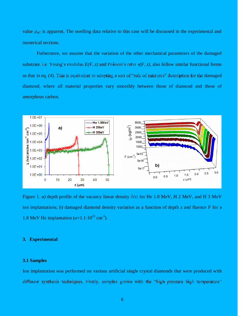
(see below). Fig. 1a shows (z) (expressed in number of vacancies per unit of length in the depth
direction, per incoming ion) in the three cases considered in this work: 1.8 MeV He, 2 MeV H and
3 MeV ions. It is apparent that a large fraction of the nuclear energy loss (which is responsible for
structural damage) occurs at end of range of ions, i.e. at depths of about 3 m, 25 m and 50 m,
respectively.
It is expected that the formation of vacancies and interstitials leads to an amorphization of the
material, i.e. a transition from the density of diamond ( d = 3.515 g cm-3
) to that of amorphous carbon
( aC 1.557 g cm-3
) [17]. The greater the damage density, the smaller the density of the damaged
diamond should become, with saturation towards the lower bound value of aC. As mentioned above,
this saturation is not predicted by SRIM Monte Carlo code, in which the interaction of each single ion
4
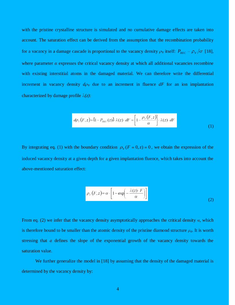
with the pristine crystalline structure is simulated and no cumulative damage effects are taken into
account. The saturation effect can be derived from the assumption that the recombination probability
for a vacancy in a damage cascade is proportional to the vacancy density V itself: VRECP [18],
where parameter expresses the critical vacancy density at which all additional vacancies recombine
with existing interstitial atoms in the damaged material. We can therefore write the differential
increment in vacancy density d V due to an increment in fluence dF for an ion implantation
characterized by damage profile (z):
(1)
By integrating eq. (1) with the boundary condition 0),0( zFV , we obtain the expression of the
induced vacancy density at a given depth for a given implantation fluence, which takes into account the
above-mentioned saturation effect:
(2)
From eq. (2) we infer that the vacancy density asymptotically approaches the critical density , which
is therefore bound to be smaller than the atomic density of the pristine diamond structure d. It is worth
stressing that defines the slope of the exponential growth of the vacancy density towards the
saturation value.
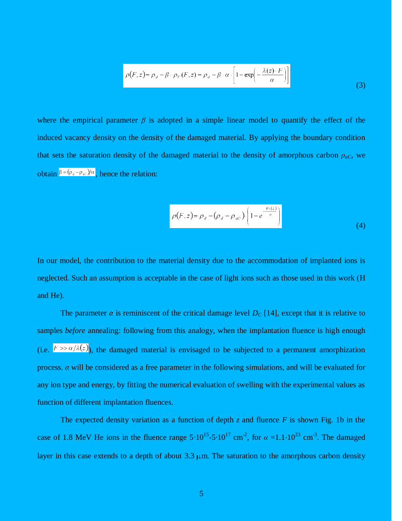
We further generalize the model in [18] by assuming that the density of the damaged material is
determined by the vacancy density by:
5
(3)
where the empirical parameter is adopted in a simple linear model to quantify the effect of the
induced vacancy density on the density of the damaged material. By applying the boundary condition
that sets the saturation density of the damaged material to the density of amorphous carbon aC, we
obtain , hence the relation:
(4)
In our model, the contribution to the material density due to the accommodation of implanted ions is
neglected. Such an assumption is acceptable in the case of light ions such as those used in this work (H
and He).
The parameter is reminiscent of the critical damage level DC [14], except that it is relative to
samples before annealing: following from this analogy, when the implantation fluence is high enough
(i.e. ), the damaged material is envisaged to be subjected to a permanent amorphization
process. will be considered as a free parameter in the following simulations, and will be evaluated for
any ion type and energy, by fitting the numerical evaluation of swelling with the experimental values as
function of different implantation fluences.
The expected density variation as a function of depth z and fluence F is shown Fig. 1b in the
case of 1.8 MeV He ions in the fluence range 5·1015
-5·1017
cm-2
, for =1.1·1023
cm-3
. The damaged
layer in this case extends to a depth of about 3.3 m. The saturation to the amorphous carbon density
6
value aC is apparent. The swelling data relative to this case will be discussed in the experimental and
numerical sections.
Futhermore, we assume that the variation of the other mechanical parameters of the damaged
substrate E(F, z) and (F, z), also follow similar functional forms
as that in eq. (4). damaged
diamond, where all material properties vary smoothly between those of diamond and those of
amorphous carbon.
Figure 1. a) depth profile of the vacancy linear density for He 1.8 MeV, H 2 MeV, and H 3 MeV
ion implantations; b) damaged diamond density variation as a function of depth z and fluence F for a
1.8 MeV He implantation ( =1.1·1023
cm-3
).
3. Experimental
3.1 Samples
Ion implantation was performed on various artificial single crystal diamonds that were produced with

7
(HPHT) method by Sumitomo were employed. Such samples are classified as type Ib, indicating a
substitutional nitrogen concentration comprised between 10 and 100 ppm. The samples are cut along
the 100 crystal direction and usually consist of different growth sectors. Secondly, samples grown with
chemical vapor deposition (CVD) technique by ElementSix were used. Such samples are characterized
by a higher purity and are classified as type IIa, having a nitrogen concentration below 0.l ppm. The
crystals consist of a single 100 growth sector. In both cases, the size is 3×3×1.5 mm3, and the two
opposite large faces are optically polished. Although characterized by different impurity
concentrations, the sample can be reasonably expected to display the same mechanical properties,
consisting in both cases in high-quality single-crystals.
3.2 Ion implantation
In order to study the damage-induced swelling process in different experimental conditions, the
samples were implanted in a broad range of fluences with different ions species and energies. 1.8 MeV
MeV He ions were implanted at the ion microbeam line of the INFN Legnaro National Laboratories
(Padova), while 2 and 3 MeV H ion implantations were performed at the external microbeam line of
the LABEC INFN facility (Firenze). In both cases, the samples were implanted in frontal geometry on
their polished surfaces. In order to achieve a uniform fluence delivery in the implantation process,
125×125 m2 square areas were implanted by raster scanning an ion beam with size of 20-30 m. In
the former case, the implantation fluence was controlled in real time by monitoring the x-ray yield from
a thin metal layer evaporated on the sample surface, while in the latter case the x-ray emission from the
beam exit window was employed, after a suitable calibration with a Faraday Cup [19]. The
implantations were performed at room temperature, with ion currents of 1 nA. In these conditions,
implantations in the fluence ranges of 1015
-1017
cm-2
could be performed in times varying from few
minutes to 1 hour.

8
3.3 Profilometry measurements
Surface swelling data were acquired at the Interferometry laboratories of the Istituto Nazionale di
Ottica Applicata (INOA) with a Zygo NewView 6000 system, which exploits white light
interferometry to provide detailed, non contact measurements of 3-D profiles. A vertical resolution of
0.1 nm was achieved over a lateral range up to 150 m, while lateral resolution varied from 4.6 m up
to 0.6 m, depending on the objective. Fig. 2 illustrates an example of a measured swelling profile for a
diamond substrate implanted with 1.8 MeV He ions. The implanted area measures approximately
110 170 m2 and the average swelling in the central region of this area is about 100 nm.
Figure 2. Experimentally measured swelling h for a 1.8 MeV He implantation (F=3.67 1016
cm-2
) using
the profilometry technique based on white light interferometry.
9
4. Numerical results
FEM simulations are performed by imposing a constrained isotropic volume expansion in the damaged
diamond substrate, which is proportional to the local density variation, as evaluated in the
above-mentioned model. This procedure is similar to imposing a thermal expansion, with the local
infinitesimal volume variation playing the role of the thermal expansion coefficient.
4.1 Finite element model
Simulations were carried out using the commercial software COMSOL Multiphysics, using the
Structural mechanics module [20]. Specimen geometry is reproduced and meshed both in 2-D and
3-D simulations. The analytical expression of eq. (4) is used, together with the damage profile (z)
resulting from SRIM simulations for 1.8 MeV He, 2 MeV H and 3 MeV H ions. The mechanical
properties of diamond and amorphous carbon are d g·cm-3
Ed =1144.6 GPa, d and
aC g·cm-3
Eg = 21.38 GPa, g respectively [17] Some uncertainty remains on the most
appropriate value to be chosen for aC, however this issue will be addressed in future works. Small
uncertainties on the remaining parameters have little influence on the swelling values obtained in
simulations. Various simulations were carried out by varying of the critical density ,
.
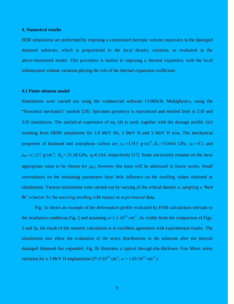
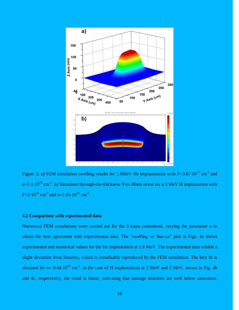
Fig. 3a shows an example of the deformation profile evaluated by FEM calculations relevant to
the irradiation conditions Fig. 2 and assuming =1.1·1023
cm-3
. As visible from the comparison of Figs.
2 and 3a, the result of the numeric calculation is in excellent agreement with experimental results. The
simulations also allow the evaluation of the stress distributions in the substrate after the internal
damaged diamond has expanded. Fig 3b illustrates a typical through-the-thickness Von Mises stress
variation for a 3 MeV H implantation (F=2·1016
cm-2
, = 1.65·1023
cm-3
).
10
Figure 3: a) FEM simulation swelling results for 1.8MeV He implantations with F=3.67·1016
cm-2
and
=1.1·1023
cm-3
. b) Simulated through-the-thickness Von Mises stress for a 3 MeV H implantation with
F=2·1016
cm-2
and =1.65·1023
cm-3
.
4.2 Comparison with experimental data
Numerical FEM simulations were carried out for the 3 cases considered, varying the parameter to
obtain the best agreement with experimental data. The plot in Figs. 4a shows
experimental and numerical values for the He implantation at 1.8 MeV. The experimental data exhibit a
slight deviation from linearity, which is remarkably reproduced by the FEM simulation. The best fit is
obtained for = 0.44·1023
cm-3
. In the case of H implantations at 2 MeV and 3 MeV, shown in Fig. 4b
and 4c, respectively, the trend is linear, indicating that damage densities are well below saturation.
11
Simulations also produce linear behaviours, and best fits are obtained for = 0.88·1023
cm-3
(2 MeV)
and = 1.65·1023
cm-3
(3 MeV), respectively.
As mentioned above, can be regarded as an effective parameter expressing the resilience of
the diamond structure to induced damage, i.e. lower values of indicate a more rapid variation of the
material density when subjected to structural damage. Despite the relative simplicity of the
above-described phenomenological model and the remaining uncertainty on the value of aC (which
will be addressed in more details in future works), the value of exhibits a systematic variation as a
function of ion penetration depth z: = 0.44·1023
cm-3
, 0.88·1023
cm-3
and 1.65·1023
cm-3
and z
for 1.8 MeV He, 2 MeV H and 3 MeV H implantations, respectively. Our result is
consistent with the experimental observation that higher damage densities are needed to graphitize
diamond at increasing depth, as resulting from several works reported in literature [9; 13; 14; 15].
This can be explained if it is considered that strong internal pressure fields arise in deeper
implantations from the rigid diamond matrix surrounding the implanted regions, which could
effectively increase the resilience of the structure to progressive amorphization and subsequent
graphitization (in the case of post-implantation annealing treatment). Qualitative evidence of this
mechanism has been identified in several works, such as [8], while in the present work the mechanism
is elucidated in quantitative terms, although by adopting a relatively simple model. In particular, it is
worth stressing that in this study a constant value of was set in the FEM simulation of the effects of
each single implantation, but the systematic variation of such parameter for implantation processes
mechanical parameter that depends from the depth in the material, where different internal pressure
fields are developed. Therefore, the different estimations of presented here are to be considered as
effective values arising from average estimations through each implantation profile.

12
Fig 4: Experimental numerical swelling values h vs. fluence F for a) 1.8 MeV He
ions, b) 2MeV H ions, and c) 3MeV H ions. Error bars are included for experimental points and
numerical values are plotted for various values of the saturation density .
13
4. Conclusions
Our modelling of surface swelling in ion-implanted diamond, carried out for the first time using FEM
simulations, yields good accordance between experimental and numerical data. In particular, the
systematic variation of empirical parameter for MeV ion implantation at increasing depth accounts
for a phenomenon that was observed qualitatively in several previous reports [9; 13; 14; 15], i.e. the
progressive resilience of the diamond lattice to graphitization at increasing implantation depth.
The results reported in this paper prove that the FEM numerical analysis can significantly
contribute to the quantitative interpretation of the structural damage mechanisms in ion-implanted
diamond, and provides encouraging insight for further in-depth analysis and systematic studies at
higher implantation fluences, where saturation of swelling values is achieved.
Acknowledgements
Compagnia di
14
References
[1]A.I. Sharkov, T.I. Galkina, A.Y. Klokov, R.A. Khmelnitskii, V.A. Dravin, A.A. Gippius, Vacuum
68 (2002) 263.
[2]P. Olivero, et al., Diamond and Related Materials 18 (2009) 870.
[3]K.L. Bhatia, S. Fabian, S. Kalbitzer, C. Klatt, W. Krätschmer, R. Stoll, J.F.P. Sellschop, Thin Solid
Films 324 (1998) 11.
[4]P. Olivero, Calusi, S., Giuntini, L., Lagomarsino, S., Lo Giudice, A., Massi, M., Sciortino, S.,
Vannoni, M., Vittone, E. , Diamond and Related Materials, in submission (2009).
[5]N.R. Parikh, J.D. Hunn, E. McGucken, M.L. Swanson, C.W. White, R.A. Rudder, D.P. Malta, J.B.
Posthill, R.J. Markunas, Applied Physics Letters 61 (1992) 3124.
[6]P. Olivero, et al., Advanced Materials 17 (2005) 2427.
[7]M.G. Allen, S. Prawer, D.N. Jamieson, R. Kalish, Applied Physics Letters 63 (1993) 2062.
[8]J.D. Hunn, S.P. Withrow, C.W. White, D.M. Hembree, Physical Review B 52 (1995) 8106.
[9]A.A. Gippius, R.A. Khmelnitskiy, V.A. Dravin, S.D. Tkachenko, Diamond and Related Materials 8
(1999) 1631.
[10]R. Kalish, A. Reznik, K.W. Nugent, S. Prawer, Nuclear Instruments & Methods in Physics
Research Section B-Beam Interactions with Materials and Atoms 148 (1999) 626.
[11]A.V. Khomich, R.A. Khmelnitskiy, V.A. Dravin, A.A. Gippius, E.V. Zavedeev, I.I. Vlasov,
Physics of the Solid State 49 (2007) 1661.
[12]J.F. Prins, T.E. Derry, Nuclear Instruments & Methods in Physics Research Section B-Beam
Interactions with Materials and Atoms 166 (2000) 364.
[13]C. Uzansaguy, C. Cytermann, R. Brener, V. Richter, M. Shaanan, R. Kalish, Applied Physics
Letters 67 (1995) 1194.
15
[14]J.O. Orwa, K.W. Nugent, D.N. Jamieson, S. Prawer, Physical Review B 62 (2000) 5461.
[15]P. Olivero, et al., Diamond and Related Materials 15 (2006) 1614.
[16]A. Ziegler, Littmark, U., (Ed.), The Stopping and Range of Ions in Solids, Pergamon, New York,
1985.
[17]Y.X. Wei, R.J. Wang, W.H. Wang, Physical Review B 72 (2005).
[18]J.F. Prins, Derry, T.E., Sellschop, J.P.F. , Physical Review B 34 (1986).
[19]L. Giuntini, M. Massi, S. Calusi, Nuclear Instruments & Methods in Physics Research Section a-
Accelerators Spectrometers Detectors and Associated Equipment 576 (2007) 266.
[20]COMSOL Multiphysics, http://www.comsol.com/.