Embed Size (px)
Citation preview

Final report for AOARD/ ITC-PAC Grant 114071
1
Final report for AOARD/ ITC-PAC Grant 114071 “Silica & Germanate Glass High Power Fiber Laser
Sources”
Prepared: January 2014
PI and Co-PI information: Principal Investigator: Prof Tanya Monro
Co investigators: A/Prof Heike Ebendorff-Heidepriem, A/Prof David Lancaster, Dr David Ottaway
Institute for Photonics and Advanced Sensing (IPAS),
The University of Adelaide, Australia
Period of Investigation: 2011-2013
Aim of the project:
The research aims of this project were to develop capability in fundamental materials, fabrication
techniques, and design of two glass systems that are leading candidates for new fiber laser architectures
operating in the 1-4 µm spectral region.
A-1 Investigate fundamental fabrication, design & thermal limitations of silica fibers (2-2.1 m lasing)
A-2 Establish techniques for improving the pump coupling to fibres via development of air structured
claddings (also known as JAC fibres, a form of double clad fibre) at these wavelengths;
A-3 Investigate development of large mode-area cores for higher power operation of fiber lasers.
B-1 Develop techniques for the fabrication and processing of germanate glass fibers to underpin the
development of active germanate fibres for fibre lasers
B-2 Explore high temperature variants of germanate glasses for improved fiber lasers
B-3 Demonstrate new forms of germanate fibre lasers for the 2-3.5 m range using Tm and Ho rare
earth dopants.
Executive Summary:
The AOARD funding for the last 3 years has contributed to development of substantive capability at IPAS
in all project target areas, and IPAS is well positioned to build on these unique and complementary
activities. With the complete relocation of fabrication facilities and fibre manufacturing to new
laboratories, ‘the Braggs’ ($94 M$), we now possess an integrated specialist fiber manufacturing facility.
We have achieved a vertically integrated capability in fabricating laser active glasses, designing both
microstructured and leaky mode fibre designs, fabricating preforms, drawing fibers, characterizing fiber

Report Documentation Page Form ApprovedOMB No. 0704-0188
Public reporting burden for the collection of information is estimated to average 1 hour per response, including the time for reviewing instructions, searching existing data sources, gathering andmaintaining the data needed, and completing and reviewing the collection of information. Send comments regarding this burden estimate or any other aspect of this collection of information,including suggestions for reducing this burden, to Washington Headquarters Services, Directorate for Information Operations and Reports, 1215 Jefferson Davis Highway, Suite 1204, ArlingtonVA 22202-4302. Respondents should be aware that notwithstanding any other provision of law, no person shall be subject to a penalty for failing to comply with a collection of information if itdoes not display a currently valid OMB control number.
1. REPORT DATE 25 FEB 2014
2. REPORT TYPE Final
3. DATES COVERED 26-09-2011 to 25-09-2013
4. TITLE AND SUBTITLE Silica and Germanate Glass High Power Fiber Laser Sources
5a. CONTRACT NUMBER FA23861114071
5b. GRANT NUMBER
5c. PROGRAM ELEMENT NUMBER
6. AUTHOR(S) Tanya Monro
5d. PROJECT NUMBER
5e. TASK NUMBER
5f. WORK UNIT NUMBER
7. PERFORMING ORGANIZATION NAME(S) AND ADDRESS(ES) University of Adelaide,School of Chemistry and Physics,Adelaide SA 5005,Australia,NA,NA
8. PERFORMING ORGANIZATIONREPORT NUMBER N/A
9. SPONSORING/MONITORING AGENCY NAME(S) AND ADDRESS(ES) AOARD, UNIT 45002, APO, AP, 96338-5002
10. SPONSOR/MONITOR’S ACRONYM(S) AOARD
11. SPONSOR/MONITOR’S REPORT NUMBER(S) AOARD-114071
12. DISTRIBUTION/AVAILABILITY STATEMENT Approved for public release; distribution unlimited
13. SUPPLEMENTARY NOTES
14. ABSTRACT The overarching aims of this project were to develop capabilities in fundamental materials, fabricationtechniques, and design of two leading candidate glass systems for new fiber laser architectures operating inthe 1-4 μm spectral region. The research involved investigation (1) of fundamental design andthermal limitations of IR silica fibers in the 2-2.1 μm range; (2) of techniques for power handlingusing air structured cladding; and (3) examination and characterization of Tm+ doped germanate glassfiber lasers that operate in the 2-3.5 μm range. Research accomplishments include 1) successfulfabrication of a range of index and microstructured guided rare-earth doped silica fibers using a modifiedchemical vapor deposition system; 2) development of an air-jacketed 2.1 μm microstructured fiberand fiber laser with demonstrated high quantum efficiency; 3) demonstration of a range of germanateglasses and optimization for laser and non-linear applications; 4) development of extruded germanatemicrostructured preforms that have been drawn into microstructured optical fibers suitable for laser andnon-linear applications; and 5) fabrication of a range of undoped and holmium doped germanatemicrostructured fibers. Judd-Ofelt modeling was undertaken to estimate branching ratios and emissioncross-sections and predict laser performance of rare earth doped germanate glass lasers. Simulations andfabrication of ?leaky-mode? large mode area fibers was also investigated. This research led to developmentof novel complex microstructured features in a relatively immature glass (especially when compared tosilica), whilst maintaining low-loss, and testing the design as a laser in the short to mid-infrared, which isone of the hardest spectral regions to operate a laser.

15. SUBJECT TERMS Photonics, Fiber Lasers, Processing, Quantum Efficiency, Fabrication
16. SECURITY CLASSIFICATION OF: 17. LIMITATION OF ABSTRACT Same as
Report (SAR)
18. NUMBEROF PAGES
40
19a. NAME OFRESPONSIBLE PERSON
a. REPORT unclassified
b. ABSTRACT unclassified
c. THIS PAGE unclassified
Standard Form 298 (Rev. 8-98) Prescribed by ANSI Std Z39-18

Final report for AOARD/ ITC-PAC Grant 114071
2
losses, and developing fiber lasers. Over the past 3 years AOARD (contract #114071) has provided a level
of funding which has allowed us to steadily grow our germanate and silica fiber laser capabilities. This
funding has led towards IPAS possessing unique capability to produce germanate glass, microstructured
germanate glass optical fibers, and microstructured rare earth doped silica fibers.
Project Outcome Summary
A-1
a. Installation and completion of a modified chemical vapor deposition system for fabricating
silica fibres.
b. Successful fabrication of a range of index guided and microstructured guided rare-earth
doped silica fibres.
A-2:
a. Pioneering development of an air-jacketed 2.1 µm microstructured fiber and fiber laser with
demonstrated high quantum efficiency.
A-3:
a. Simulations and fabrication of ‘leaky-mode’ large mode area fibers has been undertaken.
B-1:
a. An extensive program has been undertaken to develop a suite of germanate glasses
optimized for a range of applications.
B-2:
a. A range of germanate glasses have been demonstrated and optimised for laser and non-
linear applications. To predict laser performance of rare earth doped germanate glass lasers
we undertook Judd-Ofelt modeling of these systems to estimate branching ratios and
emission cross-sections.
B-3:
a. IPAS has pioneered the development of extruded germanate microstructured preforms
which have been drawn into microstructured optical fibers suitable for laser and non-linear
applications. A range of undoped and holmium doped germanate microstructured fibers
have been demonstrated. The fiber designs were driven by a desire for large mode areas to
support high peak power laser operation. Characterisation of the fibers for laser operation is
ongoing.

Final report for AOARD/ ITC-PAC Grant 114071
3
A-1: Silica fiber development:
Progress Achieved:
The contract has seen the completion and the commissioning of our end-to-end silica fibre laser
manufacturing facility which includes the construction and recent commissioning of the new dedicated
fibre draw tower laboratory at the Thebarton campus of the University of Adelaide (UoA).
Modified Chemical Vapour Deposition (MCVD) based fibre facility
The work conducted to achieve this capability includes further commissioning and refinement of the
preform manufacturing laboratory, enhancements to the modified chemical vapour deposition system,
and commissioning of an ultrasonic mill for preform drilling and milling.
With the new $3.2M silica preform facility installed in 2010, the initial focus was the production and
characterisation of a range of rare earth doped preforms. During this preform development phase we
identified and implemented a number of essential modifications to further optimise preform
manufacture. As we are the first (to the best of our knowledge) MCVD facility to use on-demand
generate hydrogen and oxygen on site (for the high temperature burner), we had to modify the
Teledyne hydrogen generator to allow it to operate in the required on-demand fashion as otherwise the
non-steady state requirements of the MCVD burner caused the hydrogen generator to continually trip.
The addition of a buffer hydrogen tank in early 2011, alleviated the hydrogen surge requirements and
remedied the hydrogen generator trip problem, and allowed the MCVD lathe to operate correctly.
Figure 1(a&b): Photographs of the (a) IPAS on-demand hydrogen/oxygen generator production capability
designed to supply the MCVD lathe, and the (b) MCVD lathe in operation

Final report for AOARD/ ITC-PAC Grant 114071
4
The first quarter of 2011 saw the completion of the$1.5M project to build a dedicated tower laboratory
at Thebarton, and final commissioning of our end-to-end silica fibre laser manufacturing facility which
then allowed us to draw the preforms to fibre and measure their characteristics. As part of the draw
tower commissioning we also upgraded the control system to digital (from analogue) which increases
the reliability, and allows easier firmware and hardware upgrades in the future. We have now
completed manufacture and testing of a range of high performing thulium doped silica fibres that have
been demonstrated as functioning fibre lasers. In addition we also commissioned an upgrade of the fibre
draw tower from the analogue control system and motors to an all digital system to the drawing
capability of the tower.
Our current progress in the preform fabrication area is demonstrated by the production of a series of
thulium doped (solution) silica preforms, with several preforms machined into both ‘D’ and hexagonal
structures which are required for drawing into double-clad fibre. These preforms were drawn to fibres
by the IPAS silica draw tower. Fig. 1(a,b) shows the IPAS hydrogen generator and MCVD preform lathe,
and fig. 2 shows a round and machined thulium doped silica preform, respectively.
A new research topic we are investigating is the use of multiple solution doping steps in order to achieve
higher thulium dopant concentrations, which is anticipated to improve fibre efficiency (IPAS #4, #5 –
described later).
Fig. 2 shows a typical refractive index of profile of a rare-earth solution doped preform. The starting
silica tube can be seen (r=2.5 to 10mm), a depressed region made by multiple deposition layers of silica
(r~1 to 2.5mm), and the high refractive index guiding core made up of solution doped aluminosilicate
and rare earth
Figure 2: A machined Thulium doped
silica preforms prior to drawing into a
fibre. The bottom preform has been in-
house machined into a hexagonal
cross-section to improve pump
absorption when operated as a
double-clad fibre laser. Both preforms
have also had ‘handles’ attached for
easier drawing into fibres.

Final report for AOARD/ ITC-PAC Grant 114071
5
Fibre draw tower facility (Thebarton Campus of the
UoA)
Figure 5: Initial preform melt initiates the fibre draw.
The silica glass ‘drop-off’ can be seen emerging from
the furnace and about to pass through the diameter
measuring gauge.
Figure 4: Photograph of the recently commissioned 6 m
Heathway silica draw tower operating.
Figure 7: View from the top of the draw tower at
the preform feeding into the furnace. Figure 8: Upgraded all-digital draw tower control unit,
which was installed during commissioning.

Final report for AOARD/ ITC-PAC Grant 114071
6
A.2: air-jacketed 2.1 µm microstructured fiber and fiber laser
Silica work component 2: The development of high power fiber silica lasers based on holmium doping Specific focus of this research over this project has been towards a large mode area air-jacketed double-clad fiber. This involves work in the following areas:
1. Fabricating more versatile depressed cladding geometries in fibers
a. Specifically we are developing processes to realise high n alumino-silicate pedestals in the fibres which allows more flexibility in modal design.
b. We are taking this approach as the standard technique which uses germanosilicate as
a pedestal has drawbacks such as a low achievable n, and it introduces high stress into the fiber.
2. Improvements in the NA of the air-jacketted holmium doped fibers. 3. Development of a higher power 1945 nm pump laser to fully characterise the holmium fiber
laser Results and Discussion: Silica work component 1: Development of depressed cladding structures for large mode area operation The results shown in Fig. 1 summarise our work in development of alumino-silicate outer cores to realize a high refractive index pedestal. This result is based on fabrication of 3 silica preforms (via modified chemical vapor deposition) where solution doping was used to introduce aluminum to the silica matrix, thus resulting in the formation of an alumino-silicate glass with a higher refractive index. This work allows us to optimize the process to realize arbitrary pedestal heights. In addition to standard solution doping, we are also investigating in-situ solution doping which allows convenient deposition of many layers to realize large pedestal widths. This contrasts with standard solution doping in that the preform does not have to be removed from the lathe to introduce each solution doped layer.

Final report for AOARD/ ITC-PAC Grant 114071
7
Fig. 1. Measured core refractive index as a function of aluminum chloride solution concentration for 3 different preforms. Shown in Fig. 2 is an optical microscope image of a holmium doped air-jacketed microstructured double-clad fiber we fabricated. Overlaid on this image are measurements of the core size as well as the strut size which is a critical parameter with regard to increasing the numerical aperture (or acceptance angle) of the fibre.
Fig. 2: Optical microscope image of the inner cladding of a holmium doped air-jacketted double-clad fiber.

Final report for AOARD/ ITC-PAC Grant 114071
8
Shown in Fig. 3 is a measurement of the NA of the fiber as a function of strut thickness which
shows the importance of achieving narrow struts for high NA. This parameter is controlled by
precisely controlling the preform temperature and active internal pressurisation of the preform
during the fiber drawing process.
Fig. 3: Measured NA of a holmium doped air-jacketted fiber as a function of strut thickness.

Final report for AOARD/ ITC-PAC Grant 114071
9
Air-Clad Holmium fiber Laser
Summary
We report the first air-jacketed holmium fibre laser. The laser operates at 2.1 µm with an internal slope efficiency of 69%, and is in-band pumped with a 1.94 µm thulium fibre laser.
I. INTRODUCTION
Holmium emission at 2.1 µm is advantageous for frequency conversion into the mid-infrared, atmospheric transmittance and high-power diffraction limited light generation. The mechanical strength and high melting point of silica make it the ideal host for high power fibre laser applications. However, its infrared vibrational absorption band results in significant attenuation above 2.1 µm [1]. This property has allowed holmium to be the longest wavelength rare-earth doped silica fibre laser.
Power scaling of robustly single-mode rare-earth fibre lasers can be limited by the onset of stimulated Raman scattering in broadband lasers and stimulated Brillouin scattering for narrow linewidth lasers [2]. These non-linear effects scale with intensity in the core, and device length. As the core area for single-mode confinement scales with wavelength, holmium should provide the largest robustly single-mode cores for silica fibre lasers.
A second limitation for power scaling is thermal load. The heat addition of the fibre due to lasing operation is related to the energy defect between the pump and lasing wavelengths. Holmium may be pumped by conventional diodes at 1.15 µm [3], however in-band pumping by direct excitation of the 5I7 energy level at 1.9 µm is the most attractive option due to low thermal heating based on the high stokes efficiency. High-power, low-cost diodes are not available at this wavelength, hence the 5I7 level is commonly tandem-pumped with thulium fibre lasers [4,5,6]. These two common pumping regimes for holmium are shown in Fig. 1.
Figure 1 – Simplified energy level diagram of trivalent holmium ion showing transitions for (a) 1.15 µm, and (b) 1.94 µm pumping regimes [7].
The majority of in-band pumped holmium fibre lasers have relied on core-pumping architectures due to absorption of the pump-wavelength by the low refractive index polymers conventionally used as an outer cladding for double-clad thulium fibre lasers. However, the

Final report for AOARD/ ITC-PAC Grant 114071
10
absorption of the pump wavelength by the polymer cladding not only results in a significant drop in device efficiency, but also acts to reduce the potential for power scaling as polymers have a relatively low thermal failure limit. For this reason the development of high power ytterbium fibre lasers has shifted away from polymer cladding [8,9]. The primary alternatives are highly fluorine-doped outer-claddings and air-jacketed fibre. The former can be fabricated by over-jacketing silica preforms with commercially available fluorine-doped silica tubes to typically achieve cladding numerical apertures (NAs) of 0.28 [9]. Recently, double-clad holmium fibre lasers have been demonstrated with low-index fluorine-doped silica cladding [10]. Air-jacketing has demonstrated NAs up to 0.88 [11]. Although the transition from core-pumped to cladding-pumped devices allows a significant increase in pump power, the reduction in pump absorption for a fixed core results in a longer cavity. The silica losses at the emission wavelength and the onset of non-linear effects restrict the length of holmium fibres for efficient high power applications [1,2]. In addition, the absorption cannot be raised by increasing the dopant concentration due to ion-clustering impacting the efficiency [12]. Hence, a low cladding to core ratio, high NA clad architecture should allow the optimum trade-off between efficiency and power scaling. This work represents the first demonstration of a double-clad, air-jacketed holmium fibre laser; moreover the design is consistent with the aforementioned requirements.
II. FIBRE MANUFACTURE
A 7-hole air clad holmium doped silica fibre was produced by fabricating a step index holmium-doped core preform inside a silica tube using a modified chemical vapour deposition (MCVD) process. The core was solution doped with a high aluminium chloride to holmium ratio to provide a high index core while reducing clustering of the holmium ions that would lead to a reduction in efficiency [12]. The strongly guiding core was chosen to allow characterization of the new fibre geometry without significant bend-induced confinement loss. The refractive index profile of the preform is shown in Fig. 2. This preform was then over-jacketed to increase the cladding diameter for structural stability and ease of handling. A 100 mm section was separated from the 200 mm long preform and the 7-hole cladding was drilled with a 2.8 mm diameter drill (1 mm/min) and a 20 kHz ultrasonic frequency (Sonic-MillTM S10 ultrasonic mill). The holes were centred on a 6 mm diameter ring around the core, to closely surround the ultra-pure MCVD deposited glass which formed the inner-cladding. This maintained a uniform density of glass surrounding the holes, thus preventing uneven expansion during fibre drawing and limiting the guiding region of the inner clad to the high purity, low water content deposition layers. High purity cladding is required due to the OH- absorption in silica at the 1.94 µm holmium pump wavelength [13]. The thickness of the deposited glass was tailored for a low core to inner-cladding area ratio to increase pump absorption and reduce device length.

Final report for AOARD/ ITC-PAC Grant 114071
11
Figure 2- Holmium doped preform refractive index profile
The fibre was drawn using active pressurisation of the preform to control the expansion of the holes. The resultant fibre had a core diameter of 10 µm, an inner cladding diameter of approximately 30 µm, and an outer diameter of 185 µm as shown in Fig. 3. In this initial fibre draw, the resultant strut thickness was larger than desired at ~2 to 3 µm, which is expected to limit the achievable inner cladding NA [11]. The fibre was then coated with a high-index polymer coating for structural stability. The fibre was found to have high mechanical strength, and could be easily cleaved using non-specialized fibre cleavers. This is unsurprising because of the large glass outer cladding and the resultant small change of 5.97x107 mm4 to 5.54x107 mm4 in the second moment of area of the fibre cross-section from a solid circular fibre. Additionally, the fracture of fibres is often caused by the propagation of micro-cracks initiated by surface defects. This fibre design positions the holes close to the centre of the fibre which is close to the neutral axis when the fibre is stressed due to bending, reducing the stress around the drilling defects.
Figure 3 – Images of the air clad, holmium doped fibre (left) and preform after drilling (right).
Drilling enables the rapid development of research fibres, in particular the investigation of novel internal fibre geometries produced using an MCVD lathe. Direct drilling of the preform eliminates HF etching of the outer cladding required for stacking as the air-cladding may be drilled in any position within the preform surrounding the desired features.

Final report for AOARD/ ITC-PAC Grant 114071
12
III. FIBRE CHARACTERISATION
Spot and broadband cutback measurements were performed by pumping the inner-cladding (region surrounded by holes) of the fibre with a thulium fibre laser and probing with a white light source (WLS). The loss in the holmium absorption band at 1.94 µm was measured as 1.4 dB/m in the inner cladding. Broadband loss spectra obtained with a super-continuum source and a Yokogawa AQ6375 optical spectrum analyser indicated a strong absorption of 1.4 dB/m at 1.4 µm, which is consistent with water contamination. The source of this contamination was identified as a fault in the chlorine flow regulator. This occurred during the production of this preform, reducing the effectiveness of the drying stage.
The divergence of the cladding was estimated for a 50 mm section of fibre. A 1.53 µm fibre laser was used to prevent core absorption preferentially absorbing higher order modes and this was coupled into the inner cladding using a 0.56 NA microscope objective. The resultant NA of the inner cladding was found to be 0.25. This relatively low result was expected due to the struts of the air cladding having greater thickness than half the wavelength [11].
IV. LASER CONFIGURATION
The laser performance of the fibre was characterized in a low-power single-pass pump configuration shown in Fig. 4. The fibre was pumped by a single-mode thulium fibre laser operating at 1.95 µm. The power of the pump was monitored using the front face reflection of a wedge in the collimated beam that was calibrated to the transmission of the wedge. The pump beam was launched into the inner-cladding of the fibre laser by use of a f = 30 mm lens. The laser cavity was bounded by an input highly reflective (HR) dichroic at 2.05 µm and the Fresnel reflection at the output end of the fibre. The laser output was separated from the pump using an angled dichroic filter HR at 1.95 µm, partially reflective at 2.05 µm, and the output power was calibrated to the transmission of filter. The lasing performance versus length of the fibre is shown in Fig. 5.
Figure 4 - Laser cutback configuration

Final report for AOARD/ ITC-PAC Grant 114071
13
Figure 5 – Laser performance of absorbed pump to calibrated output versus length.
In this configuration a maximum slope efficiency of the calibrated output to absorbed pump of 69% was achieved with a 300 mW threshold. This corresponded to a resonator length of 3.2 m. The calibrated output power versus absorbed power for this length is shown in Fig. 6. We expect that this performance was compromised by the high OH- content we measured in the fibre core. A maximum output of 900 mW was measured with a 3.8 m cavity and was limited by the pump power of the laser used for characterisation.
Figure 6 - Calibrated output power versus absorbed pump at a 3.2 m cavity length.
The output spectrum of the fibre laser was measured with the Yokogawa AQ6375 OSA and is shown in Fig. 7. Beam quality measurements are still to be performed. However imaging of the fibre output, inset in Fig. 7, suggests single trasverse mode operation consistent with the core V-number of 2.4 (the NA is based on the preform refractive index of 0.15). Optimisation of this fibre geometry should provide the basis for a new class of high power holmium fibre lasers.

Final report for AOARD/ ITC-PAC Grant 114071
14
Figure 7 - Output spectrum of the fibre laser. Inset: Typical beam profile.
V. CONCLUSION
In conclusion we have demonstrated that use of a high NA air-jacket cladding and low NA core, along with a small cladding to core area ratio, is thus ideal for efficient diffraction-limited holmium fibre laser operation.
This research represents the first step in the development of holmium-doped, air-jacketed fibre lasers, and we consider that the internal slope efficiency of 69% validates this approach.
VI. REFERENCES
[1] Kurkov, A. S., Sholokhov, E. M., Tsvetkov, V. B., Marakulin, V., Minashina, L., Medvedkov, O. I., & Kosolapov, F.. ‘Holmium fibre laser with record quantum efficiency’, IEEE J. Quantum Electron., 41(6), 492-494, (2011)
[2] Dawson, J. W., Messerly, M. J., Beach, R. J., Shverdin, M. Y., Stappaerts, E., Sridharan, A. K., Pax, P. H., et al.. ‘Analysis of the scalability of diffraction-limited fiber lasers and amplifiers to high average power’, Opt Exp., 16(17), 13240-66, (2008)
[3] Jackson, S. D., Bugge, F., & Erbert, G., ‘Directly diode-pumped holmium fiber lasers’, Opt. lett., 32(17), 2496-8, (2007) [4] Jackson, S. D. ‘Mid-infrared Holmium Fiber Lasers. IEEE J. of Quantum Electron’, 42(2), 187-191, (2006) [5] Wu, K. S., Ottaway, D., Munch, J., Lancaster, D. G., Bennetts, S., & Jackson, S. D., ‘Gain-switched holmium-doped fibre
laser’, Opt. Exp., 17(23), 20872-7, (2009) [6] Hollitt, S., Simakov, N., Hemming, A., Haub, J., & Carter, A.. ‘A linearly polarised, pulsed Ho-doped fiber laser’, Opt.
Exp. 20(15), 16285-16290, (2012) [7] Gruber, J. B., Hills, M. E., Seltzer, M. D., Stevens, S. B., Morrison, C., Turner, G., & Kokta, M. R.. Energy levels and
crystal quantum states of trivalent holmium in Yttrium aluminum garnet’, J. of Appl. Phys., 69(12), 8183, (1991) [8] Stutzki, F., Jansen, F., Eidam, T., Steinmetz, A., Jauregui, C., Limpert, J., & Tünnermann, A., ‘High average power large-
pitch fiber amplifier with robust single-mode operation’, Opt. Lett., 36(5), 689-691, (2011) [9] Dong, L., McKay, H., Fu, L., Ohta, M., Marcinkevicius, A., Suzuki, S., & Fermann, M. E.. ‘Ytterbium-doped all glass
leakage channel fibers with highly fluorine-doped silica pump cladding’, Opt. Exp, 17(11), 8962-9, (2009) [10] Hemming, A., Bennetts, S., Simakov, N., Haub, J., & Carter, A., ‘Development of resonantly cladding-pumped
holmium-doped fibre lasers’, Proc. SPIE, 8237, 82371J-82371J-9. (2012) [11] Wadsworth, W., & Percival, R., ‘Very high numerical aperture fibers’ IEEE Photon. Tech. Lett. 16(3), 843-845, (2004) [12] Kurkov, A. S., Sholokhov, E. M., Marakulin, V., Minashina, L.A., ‘Effect of active-ion concentration on holmium fibre
laser efficiency’. IEEE J. Quantum Electron., 40(5), 386-388, (2010) [13] Humbach, O., Fabian, H., Grzesik, U., Haken, U., & Heitmann, W. ‘Analysis of OH absorption bands in synthetic silica’,
J. of Non-Crystal. Solids, 203, 19-26, (1996)

Final report for AOARD/ ITC-PAC Grant 114071
15
A-3: Simulations and fabrication of ‘leaky-mode’ large mode-area fibers
Modelling and Fabrication of a Leaky Mode Depressed Clad Ho3+ Fiber Abstract: This work is an investigation of mode suppression in leaky mode fiber lasers. We
present modelling and fabrication details for a depressed cladding holmium doped silica
fiber.
1. Introduction
Power scaling of single frequency and pulsed fiber lasers are limited by the onset of non-linear effects.
The threshold for these effects can be raised by reducing the length of a fiber laser or by increasing its
core area. However, this can result in the propagation of higher order modes (HOM) that reduce output
beam quality. Recently large pitch fibers have shown promise for single mode, large mode area fiber
lasers by providing fundamental mode confinement, while allowing HOMs to leak from the core [1]. This
paper reports on the modelling and fabrication of a leaky mode, depressed clad architecture that will
allow the investigation into cladding confinement of leaky modes without the considerable
manufacturing complexity of a microstructured large pitch fiber.
2. Fiber manufacture
The depressed cladding fiber was manufactured in-house using modified chemical vapour deposition,
solution doping, and a silica fiber draw tower. A low Ho3+ concentration was chosen to allow core
pumping which also results in improved laser performance due to low ion clustering [2]. The addition of
Ho3+ was found to reduce the core refractive index which was compensated by tailoring the
concentration of AlCl3 in solution. A ring surrounding the core was then doped with BBr3 to produce the
depressed inner cladding. The refractive index profile of the preform and a microscope image of the
fiber profile are shown in Fig. 1. The preform was then drawn to a fiber with a 15 µm core radius and a
500 µm outer cladding.
Fig. 1. Refractive index profile of the fiber preform
averaged over preform length (PK2600). Inset:
Microscope image of fiber face with a 15µm core
radius.
Fig. 2. Waveguide confinement modelling as a
function of core radius of the fundamental (solid)
and first HOM (dashed) of the depressed cladding
fiber.
100 µm
Fundamental
1st HOM

Final report for AOARD/ ITC-PAC Grant 114071
16
3. Confinement modelling and laser setup
The refractive index profile of the optical fiber was approximated as a three ring step index fiber with
infinite outer cladding and the leakage from the core to outer cladding was calculated by directly solving
Maxwell’s equations [3]. Fig. 2 shows the modeled loss for the fundamental and first HOM. When
operating in a laser cavity this should provide preferential gain for the fundamental mode, thus
achieving lowest order mode operation. This fiber is now being characterised in a 1944 nm Tm3+ fiber
laser tandem pumped, 2.1 µm laser configuration.
With Ho3+ lasers near 2.1 µm being the longest wavelength silica fiber lasers, the geometric scaling of the
core for single mode guidance should provide the largest achievable mode areas in silica fiber
architectures. This makes Ho3+ an attractive gain medium for investigating power scaling in leaky mode
fiber lasers.
4. References
[1] F. Stutzki, F. Jansen, T. Eidam, A. Steinmetz, C. Jauregui, J. Limpert, and A. Tünnermann, "High
average power large-pitch fiber amplifier with robust single-mode operation" Optics Letters 36(5), 689-
691 (2011)
[2] A.S. Kurkov,, E.M. Sholokhov, A.V. Marakulin and L.A. Minashina, “Effect of active-ion concentration
on holmium fiber laser efficiency” Quantum Electron 40, 386-388 (2010).
[3] S. Warren-Smith, “Fluorescence-based chemical sensing using suspended-core microstructured
optical fibres” PhD thesis, Univ. of Adelaide (2010).

Final report for AOARD/ ITC-PAC Grant 114071
17
B-1, B-2, B-3: Germanate glass and fiber development
2011-2012
Background and project aims
While silica-based fiber lasers undeniably offer access to kW power levels, they cease to be
transparent beyond about 2.1µm, and other materials are required to access this wavelength
range. Access to the mid-infrared spectral region can be provided by the use of mid-infrared
transmitting “soft” glass such as those under development at the University of Adelaide. Truly
high power operation (>100W, say) cannot be envisaged with mid-infrared transmitting soft
glass-based fiber lasers principally because the glasses considered to date (chalcogenide,
tellurite, fluoride, etc), suffer from low damage thresholds due to low thermal stability of the
glasses.
Germanate glasses are an appealing and as yet relatively unexplored alternative choice for the
fabrication of high power fiber lasers. The combination of reasonable thermal properties (relative to soft
glasses) and relatively low phonon energy (relative to silica glass) make these glasses attractive for high
power laser operation in the wavelength range 2-3 µm, i.e. the short-infrared.
High power operation at 2 µm will allow a route to efficient pumping of non-linear fiber optic systems
for extending further into the mid-infrared. The aim of this proposal is to develop initial germanate fiber
lasers operating at 2 µm and 2.1 µm using Tm3+ and Ho3+ as the active laser ions, respectively. The
softening point of the glass is sufficiently low that current soft-glass extrusion techniques can be used to
fabricate new high efficiency laser geometries. This offers advantages not currently available to silica
fiber lasers in that it allows the formation of micro-structured fiber geometries that cannot be made in
any other way.
To develop germanate-glass based fiber lasers at ~2 µm it is first necessary to demonstrate the
fabrication of low-loss Tm and Ho-doped germanate glasses and simple fibers. We considered two
germanate glass systems:
Low-softening-point germanate glasses that can be extruded using our low-temperature
extrusion machine and expertise in complex oxide glass preform extrusion. In addition, these
glasses can be drawn using our soft glass drawing tower and building on our experience with
drawing microstructured soft glass fibres.
High-softening-point germanate glass that is commercially available from Kigre Inc and promises
higher power operation compared with low-softening-point germanate glasses. A further
advantage is that detrimental nonlinear effects such as Raman scattering will be reduced. The
high softening point of this germanate glass means that it can only be extruded using our high-
temperature extrusion machine, which is scheduled to be installed within this project.

Final report for AOARD/ ITC-PAC Grant 114071
18
Progress achieved
Capability installation
Controlled-atmosphere high-temperature glass melting capability
The development of new glasses for fibre laser application at and beyond 2µm, low water content in the
glass is critical. IPAS was awarded funding for the installation of a controlled-atmosphere high-
temperature glass melting facility, which enables melting of germanate glasses under dry atmosphere to
reduce the water content. This capability was commissioned in Aug 2011, and has been used to melt
glasses developed within this project year under controlled atmosphere conditions. It was subsequently
shifted to the IPAS Braggs ‘state of the art’ laboratory in the first half of 2013.
High-temperature extrusion machine
Under this project a high-temperature extrusion machine, required for the extrusion of preforms from
the high-softening-point germanate glass, was acquired from Kigre Inc. The extrusion rig was
successfully installed in April 2011, and subsequently moved to the new IPAS building in March 2013.
The high-temperature furnace, which will enable extrusion temperatures up to 1400oC, has also now
been commissioned.
Glass fabrication and development
Under this project we investigated three types of low-softening-point germanate glasses:
(a) Commercial bismuth-germanate glass from Schott
(b) bismuth-germanate glasses developed in-house
(b) lead-germanate glasses developed in-house
(a) Commercial bismuth-germanate glass from Schott
We acquired billets of 30mm diameter and 15mm length of low-softening germanate glass from Schott.
From one billet, we successfully extruded a 10mm diameter rod with excellent surface quality (Fig. B.2).
The rod was successfully drawn into a bare, unstructured fiber. The loss spectrum of this fiber was
measured using standard cut-back method and a white light source. The loss of the fiber is equal to the
bulk glass loss provided by Schott within loss measurement error (Fig. A.2). This demonstrates the
potential of this glass for the fabrication of fibers whose loss is only limited by material loss. The fiber
loss is 0.4 dB/m at 1.3µm, which is acceptable for short fiber laser applications. The material itself has
appreciably higher loss at 2.0µm and 2.4µm due to high water content as a result of large scale glass
manufacture.

Final report for AOARD/ ITC-PAC Grant 114071
19
Figure A.1: Photograph of our first extruded rod (2011) using Schott germanate glass (2011).
Figure A.2: Loss of bulk glass and the first extruded unstructured fiber of Schott germanate glass.
The Schott glass could successfully remelted into a glass using 1250oC melting temperature. However,
the first two remelting trials (using different mould materials) resulted in a dark brown glass, whereas
the as-received glass has a light yellow colour (Fig. A.3). Glasses with high bismuth oxide content are
know to suffer from reduction of the Bi3+ to Bi0, whereby the latter forms nanoparticles with a brown
colour. For bismuth borosilicate glasses, CeO2 is added to prevent Bi3+ reduction. Hence, for the next
remelting trial, we added 0.1wt% of CeO2 to the glass, which resulted in a glass with orange colour
(Fig. A.3), demonstrating that CeO2 is also suitable to prevent Bi3+ reduction in germanate glass. It also
shows that more than 0.1wt% CeO2 is required to completely prevent the Bi3+ reduction.
Figure A.3: Photographs of Schott germanate glasses: (left as-received, (mid)
remelted without CeO2, (right) remelted with 0.1wt% CeO2.

Final report for AOARD/ ITC-PAC Grant 114071
20
Using FTIR spectroscopy, we measured the shape and intensity of the hydroxyl (OH) group absorption
band at ~3µm (This band is often also referred to as water absorption) (Fig. A.4). The loss of this
absorption band is proportionally to the OH content and thus serves as a relative measure for the OH
content of a glass. The OH content could be reduced via remelting. For both the as-received and
remelted glass (without CeO2) the IR edge is located at ~3.5µm. This is at a relatively short wavelength
compared to germanate glasses, whose IR edge is usually located at 4-5µm. (see also results on in-house
lead-germante glasses). This suggests that the Schott glass contains SiO2 and/or B2O3, both components
exhibit high phonon energy, which shifts the IR edge towards shorter wavelengths.
Figure A.4: FTIR spectra of as-received and remelted Schott glasses showing the
OH-absorption peak at 2.9 µm and the IR edge at ~3.5µm.
To determine the composition of the germanate glass, we conducted energy dispersive X-ray
spectroscopy of the as-received and remelted Schott glass. Note that with this method B2O3 cannot be
detected. Both samples showed the same glass composition within the relatively large measurement
error of >10mol%. The approximate composition of the Schott glass was found to be 34 GeO2 – 30 Bi2O3
– 13 ZnO – 12 SiO2 – 7 BaO – 4 (La,Ce)2O3. The presence of SiO2 correlates with the short wavelength IR
edge of the Schott glass.
To test the suitability of the Schott germanate glass for complex preform extrusion, we selected a target
preform structure with 1 ring of 6 holes around the core region and a die design used for complex
preform extrusion previously. As the glass billets received from Schott have only a small volume, the
target preform diameter was only 8mm. Two germanate glass billets were successfully extruded into
preforms with 6 holes (Fig. A.5). However, the preforms show a gradual increase of tiny bubbles within
the preform from the start to the end of extrusion. These bubbles are assumed to correlate with the
tendency of the glass for Bi3+ reduction. The same tiny bubble formation was observed for a Schott lead-

Final report for AOARD/ ITC-PAC Grant 114071
21
silicate glass with high PbO content. As for Bi3+, Pb2+ can be easily reduced to Pb0 in glasses with high
PbO content.
Figure A.5: Photograph of the first extruded preform with 6 holes using Schott germanate glass.
(b) Bismuth-germanate glasses developed in-house
Within the bismuth germanate system, we first explored the glass forming region in the system
germanium oxide – bismuth oxide – tungsten oxide on the basis of the results by Yamazaki et al. [4]
(Fig. A.6). Tungsten oxide was chosen as a third component to increase the crystallization stability and
the mechanical strength.
Figure A.6: GeO2 – Bi2O3 – WO3 system and glass forming region.
A range of glass compositions was melted (Table A.1), and the glass samples were classified into glass
forming (a transparent glass can be formed), devitrification (two amorphous non-mixable phases are

Final report for AOARD/ ITC-PAC Grant 114071
22
formed) and crystallization (the glass melt crystallized while cooling or non melted residuals are found in
the glass). First glasses made showed a dark-brown color (Fig. A.7), similar to the first remelted Schott
bismuth-germanate glasses, which is attributed to Bi3+ reduction to Bi0. As for the Schott glass remelting,
we added 0.1-0.5 mol% CeO2 to the raw material batch, which resulted in a yellow glass (Fig. A.9). As the
next step, the glasses were doped with an additional 0.5 wt% of Tm2O3.
Figure A.7: Photographs of 70 GeO2 – 25 Bi2O3 – 5 WO3 glasses without
CeO2 (left) and with 0.1 CeO2 substituted for GeO2 (right).
Table A.1: Melted glass compositions in the multicomponent system GeO2-Bi2O3-WO3 and classification
and evaluation of the glass forming ability.
GeO2 Bi2O3 WO3 CeO2 Tm2O3 classification
55 39,5 5 0,5 0,3 a
55 34,5 10 0,5 0,3 b
60 34,5 5 0,5 0,3 a
65 10 20 0 0 c
69,9 25 5 0,1 0 a
70 25 5 0 0 a
70 24,5 5 0,5 0,3 a
75 19,5 5 0,5 0,3 a
80 14,5 5 0,5 0,3 c
* a-glass forming, b-devitrification, c-crystallization
Compositions of the multi-component system that formed a glass were analyzed with differential
scanning calorimetry (DSC) to find out the glass transition temperature Tg and onset of glass

Final report for AOARD/ ITC-PAC Grant 114071
23
crystallization Tc. These temperatures guide the choice of annealing, extrusion and fiber drawing
temperatures. Figure A.8 shows a DSC curve for a 55 GeO2 – 39.5 Bi2O3 – 5 WO3 glass.
300 450 600 750
-1.2
-0.8
-0.4
0.0
0.4
0.8
Tc1
Tc1
55GeO2 - 39,5Bi
2O
3 - 5WO
3
cp [J/(
g*K
)]
Temperature [C]
Tg
Figure A.8: Determination of glass transition temperature and crystallisation temperature
from cp -measurements (heat capacity) of a 55 GeO2 – 39,5 Bi2O3 – 5 WO3 glass.
To explore extrusion of the bismuth-germanate glass system, we commenced with the glass
composition 70 GeO2 – 24.5 Bi2O3 – 5 WO3 – 0.5 CeO2. We prepared a glass billet of ~3cm diameter and
~4cm height from a 150g batch. The glass billet was extruded into a rod of 10mm diameter (Fig. A.9).
Although the glass billet showed a few bubbles, no defects were visible in the extruded rod.
Unfortunately due to a gradient in the radial temperature profile within the extrusion furnace, the rod
showed severe bending. However, this can be prevented in the future by repositioning the extrusion
furnace.
Figure A9: Extruded rod using 70 GeO2 – 24.5 Bi2O3 – 5WO3 – 0.5CeO2 glass billet.
Raman spectroscopy showed that the maximum phonon energy of the bismuth glasses is with 920cm-1
(Fig. A.10) relatively high among germanate glasses. Although crystal-free glasses could be fabricated in
quantities up to 100g, detailed crystallisation investigation revealed that bismuth germanate glasses

Final report for AOARD/ ITC-PAC Grant 114071
24
demonstrate surface crystallisation in the temperature window for fibre drawing, making the glass less
suited for fibre fabrication.
Figure A.10: Raman spectrum of the 70.5 GeO2 – 24.5 Bi2O3 – 5 WO3 glass without CeO2 addition.
(c) Lead-germanate glasses developed in-house
We fabricated a range of lead germanate glasses with varying La2O3 and Na2O content (Fig. A.11). Na2O
was added as for lead-silicate glasses, small amount of Na2O prevents devitrification [5]. Addition of
La2O3 was also explored as this component increased the glass stability of tellurite glasses and allows
rare earth doping without changing the glass properties [6]. In contrast to bismuth germanates, the lead
germanate glasses did not form heavy metal nanoparticles due to reduction of heavy metal ions (i.e.
bismuth or lead) during glass melting, which is advantageous regarding reproducible glass quality.
Figure A.11: Lead-germanate glasses of different compositions.
Using 30g batches, systematic variation of the melting temperature and time demonstrated that at least
1h melting time at 1250oC is required to dissolve all raw materials and obtain a clear glass melt. Both the

Final report for AOARD/ ITC-PAC Grant 114071
25
Na-containing and the Na-free glasses could be doped with up to 2 mol% Tm2O3 (~4wt% Tm2O3) without
crystallization.
Raman spectroscopy showed that the maximum phonon energy of lead germanate glasses is with
830cm-1 (Fig. A.12) significantly smaller compared with bismuth germanate glasses. The lower phonon
energy offers negligible nonradiative multiphonon relaxation of rare earth transitions up to 2.5µm
emission wavelength.
Figure A.12: Raman spectrum of a lead-germanate glass.
To determine the position of the IR edge and the OH content (i.e. intensity of the OH absorption band at
~3µm wavelength), we prepared polished glass plates and measured the FTIR spectra. As shown in
Figure A.13, all three germanate glasses show intense water absorption band at 3µm due to melting in
ambient atmosphere. The IR edge of the two in-house lead-germanate glasses is located at ~5.5µm,
which agrees with the small phonon energy of 830cm-1 for lead-germanate glasses. This promises the
development of high-efficiency Tm3+ fiber lasers at ~2µm. As noted above, the IR edge of commercial
bismuth-germanate glass is shifted to shorter wavelength due to SiO2 content in the glass.

Final report for AOARD/ ITC-PAC Grant 114071
26
Figure A.13: FTIR spectra of lead-germanate glasses showing the OH-absorption peak at 2.9 µm and
the IR edge at ~3.5µm for the Schott glass and at ~5.5µm for lead-germanate glasses.
All germanate glasses were melted in open air thus far, resulting in relatively high water content and
thus absorption at ~3µm. Na-free glasses exhibit a lower OH content (i.e. peak absorption at 3µm)
compared with Na-containing glasses melted using the same conditions (Fig. A.14). For 30g glass batches
and 0.5-3h melting time, Tm-doping increased the OH content (Figs. A14 and A.15). In order to reduce
the water content we investigated partial replacement of PbO with PbF2. For longer melting time of 3h,
5mol% PbF2 showed a significant reduction in the OH content (Fig. A14). For shorter melting times of
0.5h, 10 mol% PbF2 was required to achieve a considerable reduction in the water content (Fig. A.15).
However, for long melting time of 5h, the water content increased compared with shorter melting time
(Fig. A15), and for 10h melting time the water content was similar to that of glasses made from PbF2–
free glass batches. The increase in water content is attributed to evaporation of the fluoride from the
glass melt, thereby approaching the same equilibrium between water in the glass melt and the
atmosphere above the glass melt. This demonstrates that use of fluoride requires careful optimization of
the fluoride content, melting time and temperature.

Final report for AOARD/ ITC-PAC Grant 114071
27
Figure A.14: FTIR spectra of different lead-germanate glass samples melted
from 30g batches at 1250oC for 30min (left) or for 1-3h (right).
Figure A.15: Water content (determined using the peak OH absorption at 3µm) for lead-
germanate glass samples melted from 30g batches at 1250oC for different melting times.
Both Na2O-containing and Na2O-free lead germanate glasses were successfully extruded into defect-free
rods (Fig. A.16). In addition, feasibility of extrusion of a structured preform was demonstrated
(Fig. A.17). From the rods and the preforms, fibres were drawn and the fibre loss in the visible to near-
infrared region was measured using the cut-back technique. For Na2O-containing glasses, shorter
melting time of 3h for the billet from which the fibre was made resulted in surface crystallization, which
led to high fibre loss (e.g. 8.4dB/m at 790nm). Increased melting time of 5h, reduced the fibre loss to
1.2dB/m at 790nm (Fig. A.18). The lowest loss could be obtained for Na2O-free lead germanate fibres.

Final report for AOARD/ ITC-PAC Grant 114071
28
The undoped fibre exhibits a minimum loss of 0.2dB/m at 1250nm and 0.6dB/m at the pump
wavelength of 790nm.
Figure A.16: (Left) 3cm diameter lead-germanate glass billet made from 150g batch and
(Right) extruded rod of 1cm diameter and 16cm length made using this billet.
Figure A.17: (Left) Extruded lead-germanate glass preform of ~1cm diameter and 26cm length,
(Middle) cross-sectional view of the preform, and (Right) cross-sectional view of the fiber.
Figure A.18: Na2O-containing germanate glass fibres: Propagation loss for the fibers made
from the extruded rod (Trial 2) and the extruded 6-hole preform (Trial 3). The melting time of
the billets used to fabricate fibers Trials 2 and 3 was 3h and 5h, respectively.
6-hole preform
rod

Final report for AOARD/ ITC-PAC Grant 114071
29
(1) Germanate glass based fibers
We investigated the feasibility of using the extrusion technique for the fabrication of preforms from germanate glass with high softening temperature. We used the commercial germanate glass BZT (Kigre Inc.) for this investigation. We successfully extruded a 10mm diameter rod and a structured preform with suspended core (Fig. B.1). Both the rod and the preform were crystal-free and exhibited good optical quality.
Figure B.1. Photograph of extruded structured preform made at IPAS from BZT germanate glass.
Using our glass flow model, the experimentally determined extrusion force values at different extrusion temperatures was determined. The temperature-viscosity behaviour of the BZT germanate glass and the two in-house developed lead-germanate glasses (GPL and GPLN) was calculated. From the temperature-viscosity curves we calculated the softening temperatures of the germanate glasses. The softening temperature of the BZT glass is ~800oC, whereas the softening temperature of in-house lead-germanate glasses is in the range 530-550oC.
The extruded BZT rod was drawn down to a bare, unstructured fibre with 160 µm outer diameter. The loss of the fibre was measured using the cutback-technique. The BZT glass demonstrates comparable minimum loss of ~1dB/m compared with in-house lead-germanate glass fibres (Fig. B.2). In contrast to the lead-germanate glass fibres, the BZG glass fibre does not show the OH vibration overtone absorption at 1.45µm. This result is consistent with bulk glass loss measurements (Fig. B.3) in the mid-infrared. The lead-germanate glasses used for fibre fabrication were melted in open air and therefore contain a larger amount of OH groups, resulting in high absorption of the fundamental OH vibration at 3µm. The BZT glass exhibits a considerable lower OH absorption, which correlates with the absence of the overtone absorption at 1.45µm. Note that lead-

Final report for AOARD/ ITC-PAC Grant 114071
30
germanate glasses melted in dry atmosphere show also low OH absorption as the BZT glass, promising low absorption >1.4µm.
Figure B.2. Bulk glass loss spectra of polished germanate glass plates.
Figure B.3. Fibre loss spectra of unstructured germanate glass fibres.

Final report for AOARD/ ITC-PAC Grant 114071
31
(2) Rare earth doped germanate fiber laser development
In this stream we achieved fabrication of a ‘proof of concept’ for a unique microstructured holmium
doped active fibre for use as a 2.1 µm laser. The laser and pump laser characteristics targeted were:
Ho3+ emission transition 5I7 – 5I8 at 2.1µm Pump source: Tm-silica fibre laser at 1.9µm
Stage 1 focussed on the identification of germanate glass compositions suitable for drawing of low-loss
fibres. To reduce risk we:
Developed low-softening temperature germanate glasses fabricated in-house AND
Optimised our extrusion fabrication techniques to high-softening temperature commercial germanate glass
Several glass systems investigated experimentally:
60 GeO2 – (35-x) PbO – x La2O3 – 5 Na2O [x = 0, 1.5, 5]
60 GeO2 – (35-x) PbO – 5 La2O3 – x Na2O [x = 0, 5]
70 GeO2 – 25 Bi2O3 – 5 WO3
With the most suitable composition identified as: 60 GeO2 – 35 PbO – 5 La2O3
We then fabricated crystal-free glass billets up to 150g (sized for fibre fabrication, Fig C.1) Ho3+ doping achieved via substitution of passive rare earth La2O3 (Fig. C.2) We measured similar bulk loss for commercial & in-house glass Commercial glass offers higher thermal stability & requires high temperature extrusion
Fig. C.1 Billet of undoped germanate fabricated
at IPAS
Fig. C.2 Spectroscopic sample of
holmium doped germanate glass

Final report for AOARD/ ITC-PAC Grant 114071
32
• To make lasers between 2-5 µm it is vital to minimize the water content of the glass (see Fig B.3 and Fig. C.3).
• To this end we developed an effective dehydration method. This involved melting the raw materials in a high purity and dry glovebox using a newly commissioned (and highly customized) high temperature (1250oC) controlled atmosphere glass melting capability. This has resulted in our in-house glass possessing comparable losses with commercial glass.
Fig. C.3 Measured losses (FTIR) of bulk germanate glasses fabricated in (1) open air (2) dry air (and with the
addition of PbF2). Nb. Due to small samples the loss near ~2 µm can’t be measured in bulk glass using this
technique.

Final report for AOARD/ ITC-PAC Grant 114071
33
(3) Spectroscopic characterization of Ho-doped germanate glass
In earlier work, we fabricated Ho-doped GPL glass with ion density of 0.951020 Ho3+ cm-3 and measured
the absorption of Ho3+ in this glass. In this work we conducted Judd-Ofelt analysis of the absorption
spectrum in order to calculate radiative lifetimes and branching ratios of the various emission
transitions. Fig. D.1 shows the experimental and calculated oscillator strengths of the various absorption
transitions. The experimental oscillator strengths were determined from the measured integral
absorption cross sections. Using these oscillator strengths, the Judd-Ofelt parameters were calculated.
The Judd-Ofelt parameters were then used to calculate oscillator strengths, radiative lifetime and
branching ratios of the various transitions (Fig. D.1). The good agreement between experimental and
calculated oscillator strengths (Fig. D.2) demonstrates the validity of the Judd-Ofelt analysis for our Ho-
doped GPL glass.
The transition of interest of this work is the 4I7 4I8 transition with emission at ~2µm. The radiative
lifetime of this transition is 7.8ms. Using the data provided in Ref [1], we calculated the non-radiative
decay from the 4I7 excited state due to multiphonon relaxation for germanate glass. Using this value, we
predicted the fluorescence lifetime to be approximately ~6.1ms, corresponding to a quantum efficiency
of 78%. Compare the quantum efficiency of Ho-doped silica fibre was reported to be only ~10% [2]. The
significantly higher quantum efficiency of Ho3+ in germanate glass relative to silica is due to the
considerably lower phonon energy of our gemanate glass (~830cm-1) compared with silica (~1100cm-1).
Fig. D.1: Spectrum of the absorption cross section of Ho3+ in GPL glass. The experimental and calculated
oscillator strength for each absorption band is shown.

Final report for AOARD/ ITC-PAC Grant 114071
34
Fig. D.2. Energy level diagram of Ho3+ in GPL glass. The values in ms are the radiative lifetimes. The
values in % are the branching ratios for the various transitions originating from an excited state. The
values in nm and µm designate the calculated wavelengths of the various emission transitions.
[1] J.M.F. van Dijk, M.F.H. Schuurmans, “On the nonradiative and radiative decay rates and a
modified exponential energy gap law for 4f–4f transitions in rare-earth ions,” J. Chem.. Phys. 78, 5317-
5323 (1983).
[2] B. Samson, G. Oulundsen, A. Carter, S.R. Bowman, “OPTICAL FIBER FABRICATION: Holmium-
doped silica fiber designs extend fiber lasers beyond 2 µm,” Laser Focus World, 8 Jan 2012

Final report for AOARD/ ITC-PAC Grant 114071
35
(4) Recent germanate glass melting and extrusion results (2013)
Nb. In early 2013 the new Braggs laboratories were completed, and all glass fabrication transitioned to
this facility over the first 6 months of 2013.
Glass melting
Towards the end of 2013, two large billets (180g) of GPNL5 glass were made successfully in the oxide
glovebox (KGe020 and KGe021) in the new Braggs facility. The FTIR spectra of the billets together with a
small GPNL5 melt made in the physics building (KGe001) are shown in Figure E.1. The significantly
reduced OH absorption at ~3µm for KGe020 and KGe021 (despite large melt size) is attributed to the
lower water content/dew point of the nitrogen in the Braggs building (<0.1ppmv/-99oC) compared to the
nitrogen in the Physics building (10ppmv/-60oC).
Figure E.1: FTIR spectra
The two billets were doped 0.2wt% Ho. As no Ho2O3 was available, we used HoF3 as raw materials for
the doping assuming that HoF3 is completely converted to Ho2O3 as follows.
2 HoF3 + 3/2 O2 Ho2O3 + 3/2 F2
However, we do not know if dry oxygen is sufficient to provide complete conversion. Recently, we have
acquired Ho2O3 raw material, which will be used for future melts. Assuming complete conversion to
Ho2O3 and using density of 5.83 g/cm3 as measured for small glass samples of GPNL5, the Ho ion density
for the two billets was calculated to be 0.43×10²⁰ Ho3+ cm-1. Using this concentration and UV-Vis-NIR
Final report for AOARD/ ITC-PAC Grant 114071
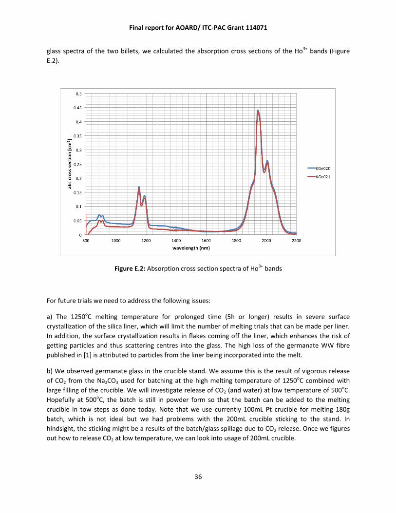
36
glass spectra of the two billets, we calculated the absorption cross sections of the Ho3+ bands (Figure
E.2).
Figure E.2: Absorption cross section spectra of Ho3+ bands
For future trials we need to address the following issues:
a) The 1250oC melting temperature for prolonged time (5h or longer) results in severe surface
crystallization of the silica liner, which will limit the number of melting trials that can be made per liner.
In addition, the surface crystallization results in flakes coming off the liner, which enhances the risk of
getting particles and thus scattering centres into the glass. The high loss of the germanate WW fibre
published in [1] is attributed to particles from the liner being incorporated into the melt.
b) We observed germanate glass in the crucible stand. We assume this is the result of vigorous release
of CO2 from the Na2CO3 used for batching at the high melting temperature of 1250oC combined with
large filling of the crucible. We will investigate release of CO2 (and water) at low temperature of 500oC.
Hopefully at 500oC, the batch is still in powder form so that the batch can be added to the melting
crucible in tow steps as done today. Note that we use currently 100mL Pt crucible for melting 180g
batch, which is not ideal but we had problems with the 200mL crucible sticking to the stand. In
hindsight, the sticking might be a results of the batch/glass spillage due to CO2 release. Once we figures
out how to release CO2 at low temperature, we can look into usage of 200mL crucible.

Final report for AOARD/ ITC-PAC Grant 114071
37
Tellurite glass melted using 100% dry oxygen atmosphere exhibited ~7 times higher OH loss at 3.3 µm
than corresponding glass melted in 80% N2 / 20% O2 dry atmosphere. This difference in loss suggests
that O2 gas used for melting has considerably higher water content. However, dew point measurements
of the O2 and N2 line today resulted in similar and low dew points of -99oC (<0.1ppmv water) for N2 and -
89oC (~1ppmv water) for O2. Further work is required to determine the impact of pure oxygen
atmosphere on OH content in glass. In addition, we need to determine the water content of the gases
once purged through the furnace liner. Note that we have gas purifier in stock in case we need to dry
gases just before entering the furnace liner. It might be worth exploring the use of 100% oxygen
atmosphere on the fibre loss. According to preliminary absolute absorption measurements, the
absorption of our glasses is only 0.2 dB/m at 1.2 µm, whereas the loss of unstructured, extruded GPNL5
fibre was measured to be ~1 dB/m at 1.2 µm, demonstrating significant contribution of scattering loss.
Small amount of Pb0 particles and/or Pt0 particles could contribute to scattering loss. 100% oxygen
atmosphere might prevent formation of any metal particles such as Pb0 and Pt0.
We also fabricated a 0.4 wt% holmium doped germanate sample, and measured the holmium
absorption as a preliminary step to fabrication of a holmium doped germanate microstructured fibre.
The measured absorption is shown (Fig. E.3) of our in-house manufactured germanate glass to produce
a microstructured preform (for a holey fibre) which was then drawn down to fibre as shown in Fig. E.6.,
with a holmium ion absorption of 1.5 dB/cm at 1945nm (5I7 – 5I8) .
800 1000 1200 1400 1600 1800 2000 2200 2400-4
-3
-2
-1
0
Ab
so
rptio
n (
dB
/cm
)
Wavelength
Ho Germanate, RM27 (0.4 mol% HoF3)
1900 1920 1940 1960 1980 2000-2.0
-1.8
-1.6
-1.4
-1.2
-1.0
-0.8
-0.6
-0.4
-0.2
0.0
Ab
so
rptio
n (
dB
/cm
)
Wavelength (nm)
Fig. E.3 Measured absorption of holmium doped germanate glass fabricated at IPAS.

Final report for AOARD/ ITC-PAC Grant 114071
38
Extrusion
The two billets KGe020 and KGe021 were extruded into preforms with 4 rings of holes (Ge-25 and Ge-26
preforms). A photograph of the cross section of the preform made from KGe020 at ~1cm from start of
extrusion is shown in Figure E.3, together with the cross sectional photograph of a 3-ring preform made
from GPL5 glass some time ago. 4-ring dies (in stock) having each a central pin were modified such that
the central pin was removed and replaced with a feed hole. Due to this modification, the central feed
hole was slightly larger than the other feed holes, resulting in enhanced flow in the centre and thus
some distortion of the holes in the inner ring. The new dies had d/Λ ratio of 0.7, whereas the previously
used 3-ring dies had d/Λ ratio of 0.5.
Figure E.4: Cross-sectional images of extruded germanate preforms: (Left) preform made
from GPNL5 billet KGe020 using die with d/Λ=0.7 and die exit diameter of 17.8mm, (Right)
preform made from GPL5 glass using die with d/Λ=0.7 and die exit diameter of 15.5mm.
In future work we will optimize the dies/structures we use. 3-ring dies have the advantage that they
result in thinner and thus longer preforms. Larger d/Λ ratio will reduce the amount of pressure required
to keep the holes open during fibre drawing.
• We have also demonstrated extrusion fabrication (Fig. E.4) of our in-house manufactured
germanate glass to produce a microstructured preform (for a holey fibre) which was then drawn
down to fibre as shown in Fig. E.6
• The measured fiber loss of the un-doped germanate fibers is shown in Table E.1 compares loss of
structured vs unstructured fibers.
• More recently we achieved fabrication of a holmium doped germanate glass fiber (OD~160 µm),
designed for large mode operation at 2.1 µm (Fig. E.7) . Characterisation of this fiber is still ongoing.
Preliminary results indicated that loss is currently high (> 10 dB/m) due to possible crystalisation due
to impurities in the glass (impure RE dopant used). Future work will eliminate these possible
impurities.
• After significant experimentation on in-house germanate, we have determined that lead-germanate
glass GeO2 – PbO – La2O3 – Na2O (GPLN)) is the most suitable compositions for fiber fabrication.

Final report for AOARD/ ITC-PAC Grant 114071
39
Figure E.5: Extruded un-doped germanate glass
preform
Figure E.6: Germanate microstructured fiber drawn from the
preform shown in Fig. E.4 Core diameter is ~ 20 µm.
Unstructured germanate fiber: 0.3 dB/m at 1.4µm
microstructured germanate fiber: 4.4 dB/m at 1.4µm
microstructured germanate fiber: 5.0 dB/m at 2.0µm
Table E.1: Measured germanate fibre losses at 1945nm for a solid fibre and a
microstructured fibre.
Figure E.7: 0.4 wt % holmium doped germanate preform drawn to fiber, OD~160µm (IPAS glass,
extrusion and drawing).

Final report for AOARD/ ITC-PAC Grant 114071
40
(5) Conclusion:
Over the last few years, the IPAS team have made strong progress towards developing a completely
vertically integrated capability in fabricating and testing microstructured germanate fiber lasers. To
the best of our knowledge this is a unique capability, and we believe we are well placed to
demonstrate this new class of high power capable short/ mid infrared germanate fiber lasers. This
research is both novel and challenging as it involves developing complex microstructured features in a
relatively immature glass (especially when compared to silica), whilst maintaining low-loss, and
testing the design as a laser in the short to mid-infrared which is one of the hardest spectral regions to
operate a laser.
Relevant papers published for this AOARD grant.
1. H. T. Munasinghe, A. Winterstein-Beckmann, C. Schiele,D. Manzani, L. Wondraczek, S. Afshar, T. M. Monro, H. Ebendorff-Heidepriem, “Lead-germanate glasses and fibers- a practical alternative to tellurite for nonlinear fiber applications” Optical Materials Express, 1488-1503, (2013)
2. “Tandem-pumped, Air-clad, Holmium-doped Silica Fibre Laser Optimization”, S.W.S. Ng, D.G. Lancaster, D.J. Ottaway, P.C. Henry, R.Kosteki and T.M. Monro, submitted to Photonics West 2013.
3. “Air-clad Holmium-doped Silica Fibre Laser”, S.W.S. Ng, D.G. Lancaster, D.J. Ottaway, P.C. Henry, R.Kosteki, and T.M. Monro, Submittted to the Australian Conference on Fibre Technology, 2012.
4. “Power scaling of short-wave infrared fibre lasers”, S.W.S. Ng, D.G. Lancaster, D.J. Ottaway, T.M. Monro, Oral paper at Frontiers in Optics Conference. Rochester, 2012.
5. “Tandem-pumped, air-clad holmium doped silica fiber laser”, S.W.S. Ng, D.G. Lancaster, D. J. Ottaway, T.M. Monro, manuscript under preparation, to be submitted to Optics Letters.
6. A. Winterstein, S. Manning, H. Ebendorff-Heidepriem, L. Wondraczek, “Luminescence from bismuth-germanate glasses and its manipulation through oxidants,” Optical Mat. Expr., 2, 1320-1328, 2012.
7. Heike Ebendorff-Heidepriem, Christian Schiele, Anja Winterstein, Lothar Wondraczek, David G. Lancaster, David Ottaway, and Tanya M. Monro, “New Germanate Glasses For Infrared Fibre Applications,” submitted to Australian Conference on Optical Fibre Technology, Sydney, Dec 2012