Embed Size (px)
Citation preview

Final Remedial Investigation Report for the Former Camp Croft Spartanburg, South Carolina
Appendices
October 2014 Contract No.: W912DY-10-D-0028 Revision 0 Page E-1 Task Order No.: 0005
APPENDIX E
INSTRUMENT VERIFICATION STRIP REPORT

Final Remedial Investigation Report for the Former Camp Croft Spartanburg, South Carolina
Appendices
October 2014 Contract No.: W912DY-10-D-0028 Revision 0 Page E-2 Task Order No.: 0005
This page intentionally left blank

FINAL INSTRUMENT VERIFICATION STRIP REPORT
REMEDIAL INVESTIGATION FORMER CAMP CROFT, SOUTH CAROLINA
USACE CONTRACT: W912DY-10-D-0028
TASK ORDER 0005
Prepared for:
US Army Engineering and Support Center, Huntsville
Prepared By:
ZAPATA INCORPORATED 301 Commercial Road, Suite B
Golden, Colorado 80401 303-278-8700 (O), 303-278-0789 (F)
June 2012
Final Remedial Investigation for Former Camp Croft Spartanburg, South Carolina
Appendices
October 2014 Revision 0
Page E-3 Contract No: W912DY-10-D-0028 Task Order No: 0005

Table of Contents
1 Introduction ................................................................................................................ 1-1 2 IVS Location and Setup ............................................................................................. 2-1 3 IVS Survey ................................................................................................................. 3-1 4 Results ........................................................................................................................ 4-1 5 Quality Control and Measurement Quality Objectives .............................................. 5-1 6 Conclusions ................................................................................................................ 6-1
List of Tables Table 2-1 IVS Survey Coordinates and ISO Orientations ................................................. 2-5 Table 4-1 ISO Detection Amplitudes and Offsets Within IVS .......................................... 4-9 Table 4-2 Six-Line Test Results (Test Item in Place) ....................................................... 4-10
List of Figures Figure 2-1 Instrument Verification Strip Location .......................................................... 2-2 Figure 2-2 IVS Area Background Survey ....................................................................... 2-3 Figure 4-1 Instrument Verification Strip Single Coil EM61-MK2 Data (Wheel Mode: Coil # 131_B).................................................................................................................................... 4-3 Figure 4-2 Instrument Verification Strip Single Coil EM61-MK2 Data (Wheel Mode: Coil # 311_B).................................................................................................................................... 4-4 Figure 4-3 Instrument Verification Strip Single Coil EM61-MK2 Data (GPS Mode)........ 4-5 Figure 4-4 IVS Channel 2 Response Results: Small ISO .................................................... 4-6 Figure 4-5 IVS Channel 2 Response Results: Medium ISO ............................................... 4-7 Figure 4-6 IVS Channel 2 Response Results: Large ISO .................................................... 4-8 Figure 6-1 Target Prioritization Method ............................................................................... 6-2 Appendix A Photographs
Final Remedial Investigation for Former Camp Croft Spartanburg, South Carolina
Appendices
October 2014 Revision 0
Page E-4 Contract No: W912DY-10-D-0028 Task Order No: 0005

Abbreviations and Acronyms AOI Area of Interest CD compact disc cm centimeters DGM Digital Geophysical Mapping GPS Global Positioning System GSV Geophysical System Verification ISO Industry Standard Objects IVS Instrument Validation Strip MEC Munitions and Explosives of Concern MPH miles per hour MRS Munitions Response Site mV millivolts QC Quality Control USAESCH US Army Engineering and Support Center, Huntsville UXO Unexploded Ordnance ZAPATA Zapata Incorporated
Final Remedial Investigation for Former Camp Croft Spartanburg, South Carolina
Appendices
October 2014 Revision 0
Page E-5 Contract No: W912DY-10-D-0028 Task Order No: 0005

1 Introduction This Instrument Verification report documents the initial phase of the investigation conducted by Zapata Incorporated (ZAPATA) for the US Army Engineering and Support Center, Huntsville (USAESCH) to locate munitions and explosives of concern (MEC) as well as non-MEC metallic items in the subsurface within Munition Response Sites (MRS) located at Camp Croft, South Carolina. The initial phase includes verification of hand-pulled EM61-MK2 digital geophysical mapping (DGM) systems using an Instrument Verification Strip (IVS) and 6-line test. The IVS is a step in the Geophysical System Verification process, a physics-based, presumptively selected technology process in which signal strength and sensor performance are initially demonstrated by static and dynamic tests on a test grid before production mapping.
Final Remedial Investigation for Former Camp Croft Spartanburg, South Carolina
Appendices
October 2014 Revision 0
Page E-6 Contract No: W912DY-10-D-0028 Task Order No: 0005

2 IVS Location and Setup On May 31st, 2012, Zapata Incorporated (ZAPATA) field geophysicists established the project IVS strip at the location shown on Figure 2-1. The site was chosen to replicate the conditions that are expected to occur in the general survey. This included the presence of trees resulting in overhead obstructions. ZAPATA positioned the IVS survey data using the EM61 MK2 in wheel mode and with the non-base corrected Trimble GEOXH. Due to the obstructed sky view GPS positioning was significantly degraded. After performing and passing quality control (QC) tests on the EM61-MK2 system in accordance with the project Work Plan, the system was used to conduct a background survey within a 26.25 foot wide by 85.3 foot long area identified as a potential location of the IVS by ZAPATA. The survey was conducted in wheel mode with a fiducial line used to help position the data during data processing placed across the width of the grid at 42 feet. The results of the background survey are shown in Figures 2-2, along with selected anomalies, IVS seed locations, and a polygon defining the area used for statistical analysis of the background data. Prior to burying the seed items, the Unexploded Ordnance (UXO) QC Supervisor used a handheld metal detector to confirm that the locations were clear of geophysical anomalies. Holes were manually dug to the appropriate depths (in accordance with the project GSV Plan) at each location. A nail was also placed flush with the surface at the edge of the survey grid. Seed items consisted of small, medium, and large industry standard objects (ISOs) in the form of threaded pipe segments, as well as two inert MKII hand grenades. The dimensions of each ISO type is shown in Table 2-1, and photographs of the actual seed items buried in the IVS are provided in Appendix A. After placement of the items, the depth of each was measured using a tape measure and the locations of the items were recorded in local coordinates from the southwest grid corner. The seed item holes were then re-filled with soil. The locations, depths and orientations of the items are shown in Table 2-1. An “as-built” map of the IVS is shown as Figure 2-3. All coordinates reported in this document and in the IVS data are listed in local X, Y feet. Note: An anomaly was detected during the background survey very near the location of a buried seed item (IVS-3, as seen in Figure 2-2). The source of this anomaly was removed prior to burial of IVS-3 by the UXO sweep team.
Table 2-1 Industry Standard Objects ISO Diameter (inches) Length (inches)
Small 1 4
Medium 2 8
Large 4 12
Final Remedial Investigation for Former Camp Croft Spartanburg, South Carolina
Appendices
October 2014 Revision 0
Page E-7 Contract No: W912DY-10-D-0028 Task Order No: 0005

Figure 2-1 Instrument Verification Strip Location
Final Remedial Investigation for Former Camp Croft Spartanburg, South Carolina
Appendices
October 2014 Revision 0
Page E-8 Contract No: W912DY-10-D-0028 Task Order No: 0005

Figure 2-2 IVS Area Background Survey
Final Remedial Investigation for Former Camp Croft Spartanburg, South Carolina
Appendices
October 2014 Revision 0
Page E-9 Contract No: W912DY-10-D-0028 Task Order No: 0005

Figure 2-3 IVS As-Built Layout
Final Remedial Investigation for Former Camp Croft Spartanburg, South Carolina
Appendices
October 2014 Revision 0
Page E-10 Contract No: W912DY-10-D-0028 Task Order No: 0005

Table 2-2 IVS Survey Coordinates and ISO Orientations
Point ID X1 (feet) Y1 (feet) Item Depth2
(inches) Item Orientation Description3
IVS-1 71.3 7.5 5 Horizontal, Perpendicular to
Direction of Travel Small ISO
IVS-2 39.3 7.5 34 Horizontal, Perpendicular to
Direction of Travel Large ISO
IVS-3 51.8 7.5 7 Horizontal, Perpendicular to
Direction of Travel Small ISO
IVS-4 32.8 20 31.5 Horizontal, Perpendicular to
Direction of Travel Large ISO
IVS-5 26.8 7.5 11 Horizontal, Perpendicular to Direction of Travel Small ISO
IVS-6 12.8 7.5 22.5 Horizontal, Perpendicular to
Direction of Travel Large ISO
IVS-7 72.3 20 11.9 Horizontal, Perpendicular
to Direction of Travel Medium ISO
IVS-8 64.3 20 18 Horizontal, Perpendicular
to Direction of Travel MKII
IVS-9 46.3 20 16.6 Horizontal, Perpendicular
to Direction of Travel Medium ISO
IVS-10 78.3 7.5 15.8 Horizontal, Perpendicular
to Direction of Travel MKII
IVS-11 19.8 20 23 Horizontal, Perpendicular
to Direction of Travel Medium ISO
IVS-12 6.8 20 11.3 Horizontal, Perpendicular
to Direction of Travel MK II
Nail 75.3 0 0 N/A Nail
Notes: 1 All coordinates in local X, Y feet
2 Measured from ground surface to the center of mass of each item.
Final Remedial Investigation for Former Camp Croft Spartanburg, South Carolina
Appendices
October 2014 Revision 0
Page E-11 Contract No: W912DY-10-D-0028 Task Order No: 0005

3 IVS Survey Following setup of the IVS grid, the EM61-MK2 man-portable (single coil) system was used to collect data along survey lines oriented east-west and spaced at 2.5 foot intervals within the grid until the entire IVS area had been covered. A fiducial line was stretched across the center of the grid at 42 feet to help position the data during data processing. Man-portable configurations used included wheel mode (single operator) and global positioning mode (GPS) mode (single operator using a Trimble GEOXH, uncorrected GPS unit). Two EM61-MK2 systems (coil serial numbers 131_B and 311_B) were tested. All data are provided on a compact disc (CD) included with this report. Because of inherent errors associated with depth measurements from a non-uniform ground surface, the IVS survey results are semi-qualitative in nature. As part of the QC testing, a small ISO item was also placed on a stand at 40 centimeters above the center of each EM61-MK2 coil and the response was recorded to provide a quantitative measure of the system’s response to the small ISO. Results of these tests are presented below in Section 4.0.
Final Remedial Investigation for Former Camp Croft Spartanburg, South Carolina
Appendices
October 2014 Revision 0
Page E-12 Contract No: W912DY-10-D-0028 Task Order No: 0005

4 Results Following acquisition, raw fiducial (wheel mode) EM61 MK2 data were converted to xyz files and positioned using ZAPATA’s Make XYZ program. The resulting data files were then processed and plotted in Geosoft’s Oasis Montaj to produce gridded xyz data maps. Targets were selected from the gridded data using the Blakely Test algorithm. Figures 4-1 and 4-2 show the gridded data from the two single-coil EM61 MK2 surveys conducted in wheel mode; Figure 4-3 shows the results of the survey conducted in GPS mode. Figures 4-4 through 4-6 display the amplitude response collected over each of the IVS seeds using each survey configuration plotted against the expected responses calculated by the Naval Research Laboratory and the envelope created by plotting lines 20% higher and lower than those expected responses. Results of the QC tests (ISO placed horizontally at the center of each coil at 40 centimeters [cm] above the coil) for each coil are also plotted on Figure 4-4 (note: since no expected response data exists for 40 cm below the coil [-2 cm below ground] the values are plotted at 0 cm below ground, or 42 cm below the coil). Table 4-1 displays the detected amplitudes and measured offsets from the known seed item locations using only the wheel mode survey method. As shown in Figure 4-3, the uncorrected GPS signal did not maintain a positional accuracy sufficient to locate the EM61 MK2 data with adequate precision in accordance with the Work Plan. This was due to the vegetative tree cover which blocked the GPS satellite signal and prevented the attainment of sub-meter accuracy. All seed items were detected during the IVS survey at above background levels, with the exception of two MKII hand grenades (IVS-8 and IVS-10), which were buried horizontally at depths significantly deeper than a MKII grenade would be expected to be found (18 inches and 15.8 inches below ground surface, respectively). As shown in Figures 4-5 and 4-6, responses from the IVS seeds and QC tests fall within the expected range for all buried large ISOs. In the cases of the remaining small and medium ISOs (Figures 4-4 and 4-5), the deepest items were detected within the expected range of responses; however, the remaining responses for the small and medium ISOs were detected outside the predicted response envelope (all were greater than the upper 20% expected values). The shallowest medium ISO was detected at very near (within 1.5 mV of) the upper 20% expected value. Variations in responses are likely due to variables introduced during surveys, which may affect instrument measurements. These variables include: • Depth Measurement: if terrain is not completely flat around excavated holes, then an average of the ground level must be determined in the field, resulting in differences in measured seed item depths of up to several centimeters. • Instrument Path: while the instrument operator attempts to maintain as central a path over the seeded items as possible, slight variation to either side can impact the measured response.
Final Remedial Investigation for Former Camp Croft Spartanburg, South Carolina
Appendices
October 2014 Revision 0
Page E-13 Contract No: W912DY-10-D-0028 Task Order No: 0005

• Measurement Location: because the instrument records are at set measurement intervals, the actual measured response may not be directly over the item when it is at the same measurement location as is used to predict the response curve. • Instrument “Bounce”: unless terrain is absolutely flat around the excavation, the transmit/receive coil can vary in height above the ground surface by several centimeters from the height used to predict the response curve. Because there is limited ability to control these variables, a static test with a small ISO held horizontally at a fixed distance from the transmit/receive coil was used to measure instrument response from both coils used during the IVS. The responses recorded during the tests were within approximately 10 percent of the upper range of the expected response in the horizontal configuration for a small ISO at 42 cm below the coil. Since the ISO was actually 2 cm closer to the coil (40 cm) during the tests, the expected response from each instrument would be slightly higher than that expected at 42 cm away; this is what was observed during both static tests. The survey over the IVS seeds can also be used to demonstrate instrument detection of the ISOs while in motion, demonstrate appropriate falloff of response from deeper items, measure representative background response, and demonstrate positioning system accuracy under survey conditions. As shown in Table 4-1, all items detected during the IVS survey were located within 1 meter of the know location of each seed item. Anomaly responses over the test items ranged from 4.1 mV to 53.3 mV on Channel 2 (responses collected over ISO-8 and ISO-10 were very near or below the maximum background level of 1 mV). Signal to noise ratios calculated for the items ranged from 0.4 (MKII grenade) to 70.43 (large ISO). To determine background levels at the IVS, a polygon area (shown on Figure 2-2) was selected for statistical analysis within an area free of apparent anomalies within the background survey data collected by the EM61 MK2. The results of the analysis conducted in Geosoft Oasis Montaj indicate relatively low levels of background noise at the IVS. Statistical results derived from the leveled, demedian filtered Channel 2 data indicate a maximum value of 1.16 millivolts (mV), a minimum of -2.57 mV, a mean of 0.22 mV, and a standard deviation of 0.58 mV. While these not necessarily representative of background conditions across the entire site, these values were used as a starting point for determining anomaly selection criteria.
Final Remedial Investigation for Former Camp Croft Spartanburg, South Carolina
Appendices
October 2014 Revision 0
Page E-14 Contract No: W912DY-10-D-0028 Task Order No: 0005

Figure 4-1 Instrument Verification Strip Single Coil EM61-MK2 Data (Wheel Mode: Coil # 131_B)
Final Remedial Investigation for Former Camp Croft Spartanburg, South Carolina
Appendices
October 2014 Revision 0
Page E-15 Contract No: W912DY-10-D-0028 Task Order No: 0005

Figure 4-2 Instrument Verification Strip Single Coil EM61-MK2 Data (Wheel Mode: Coil # 311_B)
Final Remedial Investigation for Former Camp Croft Spartanburg, South Carolina
Appendices
October 2014 Revision 0
Page E-16 Contract No: W912DY-10-D-0028 Task Order No: 0005

Figure 4-3 Instrument Verification Strip Single Coil EM61-MK2 Data (GPS Mode)
Final Remedial Investigation for Former Camp Croft Spartanburg, South Carolina
Appendices
October 2014 Revision 0
Page E-17 Contract No: W912DY-10-D-0028 Task Order No: 0005

Figure 4-4 IVS Channel 2 Response Results: Small ISO
Camp Croft IVS: Surveyed EM61 MK2 Channel 2 Responses to Small ISOCompared With Predicted Responses- Least Favorable Orientation
0
5
10
15
20
25
30
35
-5 5 15 25 35 45
Depth Below Ground Surface (cm)
Peak
Sig
nal (
mV
)
Expected Repsonse
20 % Lower Bound
20% Upper Bound
IVS Response
Static QC Response Coil131_B
Static QC Response Coil311_B
Final Remedial Investigation for Former Camp Croft Spartanburg, South Carolina
Appendices
October 2014 Revision 0
Page E-18 Contract No: W912DY-10-D-0028 Task Order No: 0005

Figure 4-5 IVS Channel 2 Response Results: Medium ISO
Camp Croft: Surveyed EM61 MK2 Channel 2 Responses to Medium ISOCompared With Predicted Responses- Least Favorable Orientation
0
20
40
60
80
100
120
140
160
180
200
-5 5 15 25 35 45 55 65 75
Depth Below Ground Surface (cm)
Peak
Sig
nal (
mV
)
Expected Repsonse
20 % Lower Bound
20% Upper Bound
IVS Response
Final Remedial Investigation for Former Camp Croft Spartanburg, South Carolina
Appendices
October 2014 Revision 0
Page E-19 Contract No: W912DY-10-D-0028 Task Order No: 0005
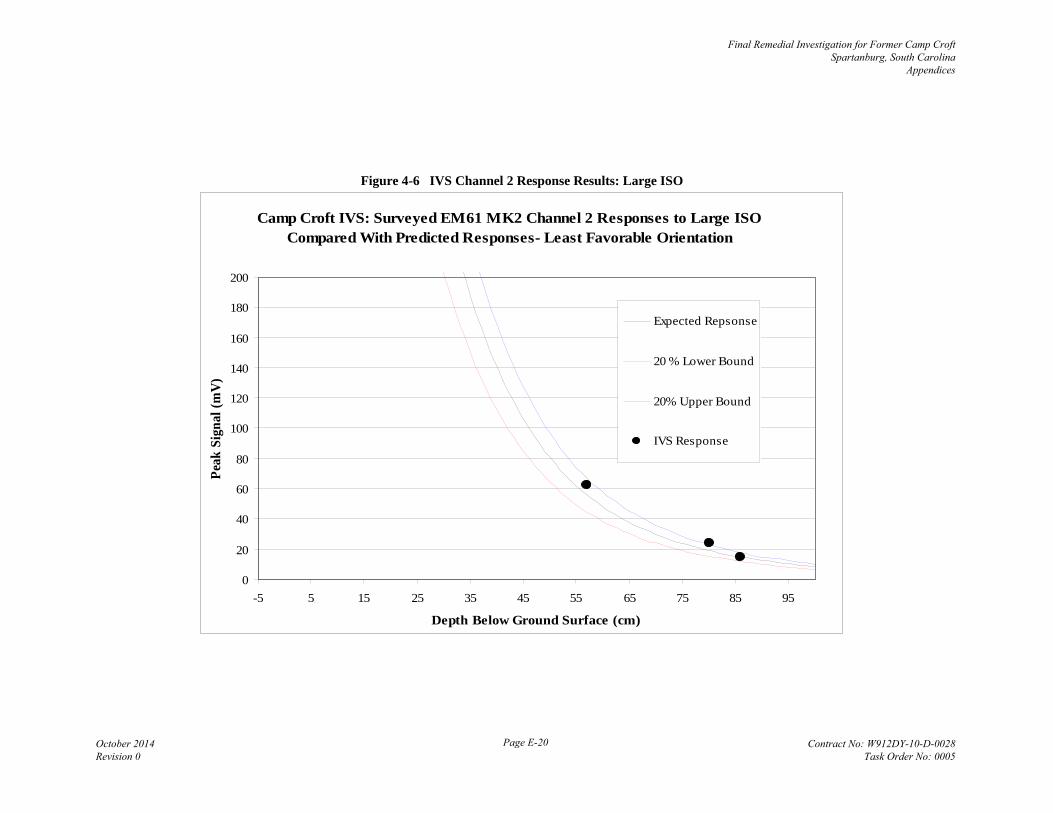
Figure 4-6 IVS Channel 2 Response Results: Large ISO
Camp Croft IVS: Surveyed EM61 MK2 Channel 2 Responses to Large ISOCompared With Predicted Responses- Least Favorable Orientation
0
20
40
60
80
100
120
140
160
180
200
-5 5 15 25 35 45 55 65 75 85 95
Depth Below Ground Surface (cm)
Peak
Sig
nal (
mV
)
Expected Repsonse
20 % Lower Bound
20% Upper Bound
IVS Response
Final Remedial Investigation for Former Camp Croft Spartanburg, South Carolina
Appendices
October 2014 Revision 0
Page E-20 Contract No: W912DY-10-D-0028 Task Order No: 0005

Table 4-1 ISO Detection Amplitudes and Offsets Within IVS
Point ID Ch2 response (mV)
Signal to Noise Ratio
Offset from Known Location
(m) Description
IVS-1 16.9 3.07 0.76 Small ISO
IVS-2 15.1 3.75 0.16 Large ISO
IVS-3 12.4 2.16 0.34 Small ISO
IVS-4 24 9.09 0.12 Large ISO
IVS-5 4.1 NC1 0.45 Small ISO
IVS-6 62.6 70.43 0.07 Large ISO
IVS-7 42 30.29 0.15 Medium ISO
IVS-8 1.01* NC1 0.04 MKII
IVS-9 26 8.93 0.13 Medium ISO
IVS-10 1.47* NC1 0.08 MKII
IVS-11 7 0.77 0.06 Medium ISO
IVS-12 7.4 0.40 0.12 MK II
Nail 53.3 NC1 0.0 Nail
*Not detected above background levels. 1 NC = Value not calculated
A 6-line test was also conducted by ZAPATA in accordance with the work plan. During the test, a field crew member pulled the EM61 MK2 in wheel mode over a test line 50 feet in length. Initially, the line was collected twice in opposite directions with no test item in place. Four lines were then collected with an approximately 2.5 inch diameter trailer ball placed in the center of the test line at the 25 foot mark. Two lines were collected at a normal pace in opposite directions over the item, and one line each was collected in a single direction at a fast and slow pace over the item. The results of the 6-line test with the test item in place are shown in Table 4-2, which shows that the test item was located within 1 meter of the known location and within 20% of the mean response at each speed, which meets the .QC standards set forth in the Work Plan.
Final Remedial Investigation for Former Camp Croft Spartanburg, South Carolina
Appendices
October 2014 Revision 0
Page E-21 Contract No: W912DY-10-D-0028 Task Order No: 0005

Table 4-2 Six-Line Test Results (Test Item in Place)
Line1 Anomaly
Location Offset (m)
Response Ch 1 (mV)
Response Difference (%)
Speed Over Test Item2 (mph)
3 (Normal Pace) 0.08 120.6 4.69% 2.65
4 (Normal Pace) 0.06 122.1 5.99% 2.30
5 (Fast Pace) 0.19 109 5.38% 4.41
6 (Slow Pace) 0.06 118.4 2.78% 1.15
1 Lines 1 and 2 were collected without the test item in place. 2 Mean speed calculated over the entire width of the test item anomaly.
Based on the IVS and 6-line test results, the following approach is recommended for anomaly selection:
1. A target selection threshold of 3 mV on Channel 2 for all EM61-MK2 surveys is recommended for anomalies that display decay characteristics consistent with those typically caused by the presence of metallic items; i.e. a stepwise decrease in amplitude across each of the time channels (Channels 1 through 4) is seen in profile and the anomaly shows a parabolic decrease in amplitude to either side of the peak response.
2. Target selection criteria should be re-evaluated if background noise in any individual grid or survey area is significantly higher than what is observed in the IVS.
3. Based on the 6-line test, the QC standards for both instrument response and data positioning were met using a maximum data collection speed of 4.4 mph. However, due to uneven terrain expected across much of the survey areas at Camp Croft, which may affect instrument response and subsequent anomaly detection and classification, a maximum speed of 3.5 mph will be used as the upper threshold for meeting the speed requirement as described in Table 20 of the Work Plan.
Final Remedial Investigation for Former Camp Croft Spartanburg, South Carolina
Appendices
October 2014 Revision 0
Page E-22 Contract No: W912DY-10-D-0028 Task Order No: 0005

5 Quality Control QC tests were performed as specified in Table 20 and Appendix K of the project Work Plan. No discrepancies were noted in terms of instrument functionality and all test results were within tolerances stated in the WP. Survey data also met all minimum QC requirements; however, as shown in Figure 4-3, the Trimble GEOXH did not provide sufficiently accurate data locations to evaluate the effectiveness of the positioning unit. All QC test data as well as an Access table showing test results and measured survey metrics are provided on a CD included with this report.
Final Remedial Investigation for Former Camp Croft Spartanburg, South Carolina
Appendices
October 2014 Revision 0
Page E-23 Contract No: W912DY-10-D-0028 Task Order No: 0005

6 Conclusions ZAPATA set up and performed an IVS survey over an approximately 26 foot by 85 foot grid containing buried seed items using hand pulled EM61 MK2 coils in both wheel mode and with a GPS unit (GeoXH) prior to conducting DGM surveys within Camp Croft. ZAPATA also conducted a 6-Line test to show instrument functionality at multiple speeds and to determine the maximum data collection speed for the project (3.5 mph). The systems were verified as being within industry standards and met the QC standards described in the Work Plan; however, due to site conditions (heavy tree cover) the Trimble GeoXH was unable to position the survey data within 1 meter. As shown in Table 4-1 and Figure 4-6, instrument responses to buried ISOs were found to be within the expected range for large ISOs, and slightly higher than expected for the small and medium ISOs during the IVS (Figures 4-4 and 4-5). Static tests conducted using two EM61 MK2 coils with a small ISO held at 40 cm above each coil resulted in responses that were close to (approximately 10% greater than) those values expected for an item held slightly further (42 cm) away, which suggests that the coils were functioning properly during the surveys. Minor deviations away from the center of the IVS to either side of the ISOs, as well as uneven ground in the vicinity of the ISOs may also have impacted the measured responses of each method during the survey. Based on the results of this IVS anomaly selection criteria will be set at 3 millivolts on Channel 2 for all data sets. Due to low ambient background levels detected during the IVS surveys, advanced target characterization will not likely be necessary at Camp Croft. However, if geologic influence or fluctuations in ambient background levels become apparent in some areas and makes individual anomaly selection difficult, ZAPATA will discuss with the USAESCH project geophysicist potential changes to the data evaluation and/or target selection procedures. Target prioritization for intrusive investigation, when necessary, will be conducted with the concurrence of the USAESCH project geophysicists in a manner similar to the reporting table within EM 1110-1-4009 and shown as Figure 6-1.
Final Remedial Investigation for Former Camp Croft Spartanburg, South Carolina
Appendices
October 2014 Revision 0
Page E-24 Contract No: W912DY-10-D-0028 Task Order No: 0005

Figure 6-1 Target Prioritization Method
Final Remedial Investigation for Former Camp Croft Spartanburg, South Carolina
Appendices
October 2014 Revision 0
Page E-25 Contract No: W912DY-10-D-0028 Task Order No: 0005

Appendix A
Photographs of Seed Items
Final Remedial Investigation for Former Camp Croft Spartanburg, South Carolina
Appendices
October 2014 Revision 0
Page E-26 Contract No: W912DY-10-D-0028 Task Order No: 0005

ISO-1: Small ISO
Final Remedial Investigation for Former Camp Croft Spartanburg, South Carolina
Appendices
October 2014 Revision 0
Page E-27 Contract No: W912DY-10-D-0028 Task Order No: 0005

ISO-2: Large ISO
Final Remedial Investigation for Former Camp Croft Spartanburg, South Carolina
Appendices
October 2014 Revision 0
Page E-28 Contract No: W912DY-10-D-0028 Task Order No: 0005

ISO-3: Small ISO
Final Remedial Investigation for Former Camp Croft Spartanburg, South Carolina
Appendices
October 2014 Revision 0
Page E-29 Contract No: W912DY-10-D-0028 Task Order No: 0005

ISO 4: Large ISO
Final Remedial Investigation for Former Camp Croft Spartanburg, South Carolina
Appendices
October 2014 Revision 0
Page E-30 Contract No: W912DY-10-D-0028 Task Order No: 0005

ISO-5: Small ISO
Final Remedial Investigation for Former Camp Croft Spartanburg, South Carolina
Appendices
October 2014 Revision 0
Page E-31 Contract No: W912DY-10-D-0028 Task Order No: 0005

ISO-6: Large ISO
Final Remedial Investigation for Former Camp Croft Spartanburg, South Carolina
Appendices
October 2014 Revision 0
Page E-32 Contract No: W912DY-10-D-0028 Task Order No: 0005

ISO-7: Medium ISO
Final Remedial Investigation for Former Camp Croft Spartanburg, South Carolina
Appendices
October 2014 Revision 0
Page E-33 Contract No: W912DY-10-D-0028 Task Order No: 0005

ISO-8: MKII Hand Grenade (Inert)
Final Remedial Investigation for Former Camp Croft Spartanburg, South Carolina
Appendices
October 2014 Revision 0
Page E-34 Contract No: W912DY-10-D-0028 Task Order No: 0005

ISO-9: Medium ISO
Final Remedial Investigation for Former Camp Croft Spartanburg, South Carolina
Appendices
October 2014 Revision 0
Page E-35 Contract No: W912DY-10-D-0028 Task Order No: 0005

ISO-10: MKII Hand Grenade (Inert)
Final Remedial Investigation for Former Camp Croft Spartanburg, South Carolina
Appendices
October 2014 Revision 0
Page E-36 Contract No: W912DY-10-D-0028 Task Order No: 0005

ISO-11: Medium ISO
Final Remedial Investigation for Former Camp Croft Spartanburg, South Carolina
Appendices
October 2014 Revision 0
Page E-37 Contract No: W912DY-10-D-0028 Task Order No: 0005

ISO-12: MKII Hand Grenade (Inert)
Final Remedial Investigation for Former Camp Croft Spartanburg, South Carolina
Appendices
October 2014 Revision 0
Page E-38 Contract No: W912DY-10-D-0028 Task Order No: 0005