Embed Size (px)
DESCRIPTION
Â
Citation preview
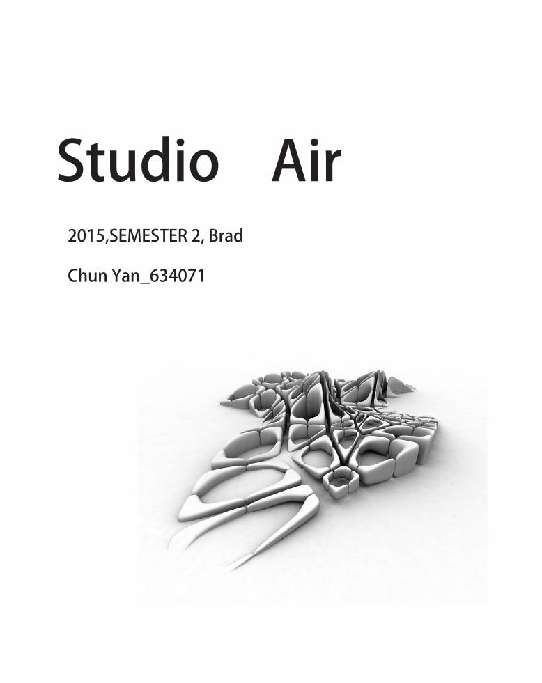
Studio Air2015,SEMESTER 2, Brad
Chun Yan_634071
3 ABOUT ME
4 A.1.1Design Futuring -Precedents 1
6 A.1.2 Design Futuring -Precedents 2
6 A.2 Design Computation
8 A.2.1 Design Computation-Precedent 1
9 A.2.2 Design Computation-Precedent 2
10 A.3 Composition/Generation
12 A.3.1 Composition/Generation-Precedent 1
13 A.3.2 Composition/Generation-Precedent 2
14 A.4 Conclusion
16 A.5 Learning Outcome
18 A.6.1 Appendix-Algorithmic Skeches
20 A.6.2 Appendix-Reference List
Table Of Content
Hi everyone. My name is Chun Yan. I came to Australia
from China two years ago to further my study in University of
Melbourne. I started to learn Chinese traditional painting when
I was 5 years old. At the beginning, I just drew what the teacher
asked me to draw. Tracing and copying can improve my painting
techniques and form basic ideas in my mind. In development,
the teacher pushed me to do some creation after my drawing
skills reach a mature level.
Similarly, my process of architecture study follows this approach
as well. Although I loved drawing since I was a little child, it was
really accidental that I chose architecture as my major. Before
entering the university, I used to consider design is a simple
process. It is mostly just drawing and imagination. However,
during 2 years’ study, I perceive that architecture is much more
than just drawing and imagination. Rationality, sustainability,
history and connections in both conceptual aspects and physical
aspects are all essential. That’s what an architect should consider
during the creation.
Before attending ADS: air, I have done several studios such as
Designing environments and water studio. The projects I did
in the past two years played a lot with geometry. With the help
from my tutors, I tried various different forms and ideas on my
projects. However, I focused too much on the appearance of the
building, and ignored the design brief, practicability and even
sustainability. What I missed is precisely architecture’s essence.
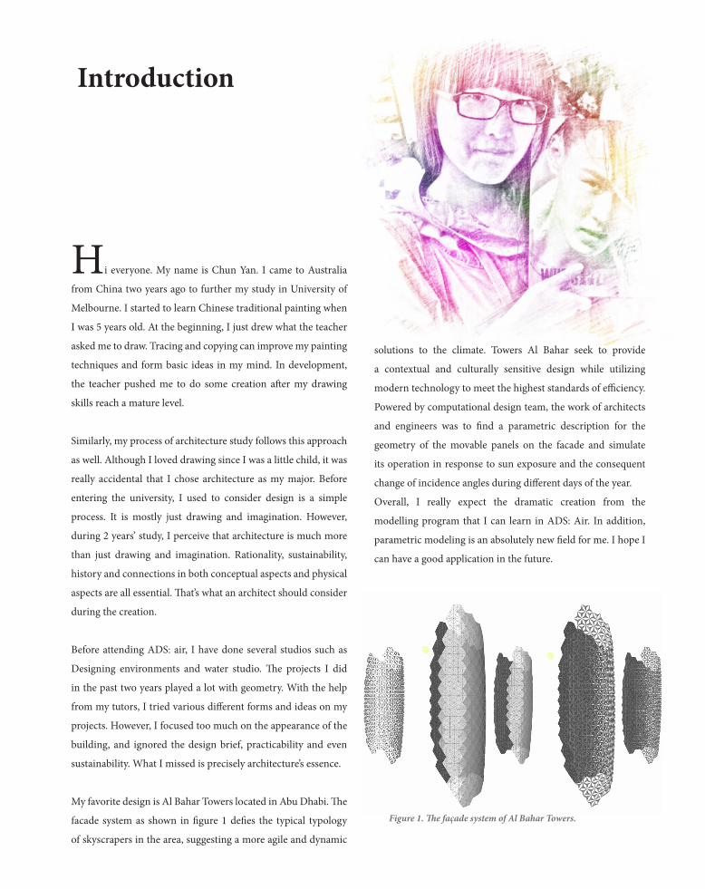
My favorite design is Al Bahar Towers located in Abu Dhabi. The
facade system as shown in figure 1 defies the typical typology
of skyscrapers in the area, suggesting a more agile and dynamic
solutions to the climate. Towers Al Bahar seek to provide
a contextual and culturally sensitive design while utilizing
modern technology to meet the highest standards of efficiency.
Powered by computational design team, the work of architects
and engineers was to find a parametric description for the
geometry of the movable panels on the facade and simulate
its operation in response to sun exposure and the consequent
change of incidence angles during different days of the year.
Overall, I really expect the dramatic creation from the
modelling program that I can learn in ADS: Air. In addition,
parametric modeling is an absolutely new field for me. I hope I
can have a good application in the future.
Introduction
Figure 1. The façade system of Al Bahar Towers.
The design outcome of Beijing national stadium
requires that it should be sustainable. The stadium
adopted advanced and feasible environmental
protection technique and building materials
to make maximum use of natural ventilation
and natural light. In addition, the rainwater
collected system, the use of renewable geothermal
energy and the application of solar photovoltaic
technology greatly save energy. The idea of its
structure came from bird’s nest. Distinctively, it is
a bird’s nest which is not completely sealed. This
ingenious design was not only made to get a unique
appearance, but also built to give the users a fluent
air circulation and light.
Humanistic Design
The seating in the Beijing National Stadium were
designed as a bowl shape. The layout of the seating
is well-arranged to guarantee that each audience
will have a distance of 140metres from their seat
to the center of field. Furthermore, there are
approximately 200 wheelchair seating for disabled
people. Someone may propose it is very general in
A.1.1Design Futuring -Precedents 1
many public places. Distinctively, these seating has
a higher view than other normal seating. This small
but effective design ensure that disabled people
can have the equal version to normal audience.
Overall, many architectural experts believe that
‘bird’s nest’ will not only establish a distinct
and historical remarkable building for 2008
Beijing Olympic games, but also has an initiating
significance in the world’s architectural history.
The Beijing National Stadium will provide
historical testimony for the development of both
Chinese and world architecture.
Figure 2. Beijing National Stadium
Figure 3. Beijing National Stadium in Grasshopper
Beijing National Stadium
Beijing, China
Architect: Pierrede Mueron
Xinggang Li
Herzog Company

Geometry
The Lotus temple is famous for its architectural splendor. It is a
continuation of this rich tradition. As the architect, Mr. Fariborz
Sahba had travelled in India extensively to study the architecture
of this land before undertaking the design of the temple. He was
impressed by the design of the fantastic temples, as well as by the
art and religious symbols wherein the lotus invariably played an
important role. He was influenced by this experience, and in an
attempt to bring out the concept of purity, simplicity and fresh-
ness of the Bahai Faith. Mr. Fariborz Sahba conceived the Temple
in the form of a lotus. The temple gives the impression of a half-
open lotus flower, afloat, surrounded by its leaves. Each compo-
nent of the temple is repeated nine times.
A.1.2 Design Futuring -Precedents 2
The beautiful concept of the lotus, as conceived by the
architect, had to be converted into definable geometrical
shapes such as spheres, cylinders, toroid and cones. These
shapes were translated into equations, which were then
used as a basis for structural analysis and engineering
drawings. The resultant geometry was so complex that it
took the designers over two and a half years to complete
the detailed drawings of the temple. An attempt is made
below to describe this complex geometry in simple terms.
The idea of bionical and geometrical architecture did
inspired the architectural industry not only in India but
many other countries.
Figure 4. The Lotus Temple
Figure 5. The Lotus Temple plan
Figure 6. The Lotus Temple Elevation
Lotus temple
Delhi, India
Architect: Fariborz Sahba

A.2 Design Computation
Throughout the development of the human history and industry,
people keep developing machineries. Machineries reduce the consumption
of human resource and bring us convenience. The invention of the
computer has absolutely changed the way we work in different industry.
In the following paragraphs, the tremendous possibility, unlimited
potential and the profound impact that computational design brings will
be discussed respectively.
The digital design does brought architectural industry great changes. It
is significant to distinguish computation and computerization. Peter has
described ‘computation’ as the way that ‘allows designers to extend their
abilities to deal with highly complex situations.’1 In addition, computation
has produced much more essential possibilities and opportunities for the
architectural industry. In the development of architecture history, there is
always a kind of unique and particular building form that can represent
the characteristics and trend of architecture in that period. For example,
pyramid represents ancient Egypt while steel-and-glass skyscrapers
obviously represent modern architecture. In 21st century, computation
design is exactly a breakthrough in architecture development nowadays.
To put it simply, computation is a new approach to design for the
architects. The most important difference between computing and
traditional architectural design method is that the project can be modified
anytime and anywhere in a computational approach, while the traditional
way is a bit inflexible and hard to make some changes. The modification
is definitely an important step. For architects, a lot of elements need to
be considered. Computation design provide more possibilities, potentials
and options for architects because of its flexibility and modifiability.
Furthermore, computing ‘defines a digital continuum from design to
production, from form generation to fabrication design.’2 Computational
design brings new solutions for a project from its original design to the
completion. In addition, computation requires computer techniques
as architects use computation software to design. Therefore, the new
approach has arisen a group of specialized consultancy and promoted the
1.BRADY PETERS, ‘COMPUTATION WORKS: THE BUILDING OF ALGORITHMIC THOUGHT’, ARCHITECTURAL DESIGN, 83.2, (2013), 08-15.2.RIVKA OXMAN, ROBERT OXMAN, THEORIES OF THE DIGITAL IN ARCHITECTURE, 1 EDN (LONDON: ROUTLEDGE, 2014), P. 1-10.
development and cooperation between each industry.
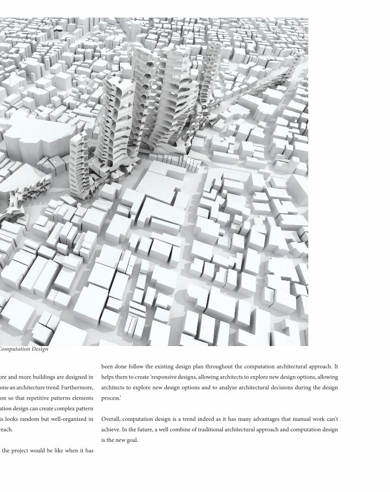
Along with the development of computing technologies, more and more buildings are designed in
geometrical and curvy shapes, and this phenomenon has become an architecture trend. Furthermore,
accurate algorithms can be achieved throughout computation so that repetitive patterns elements
have been more and more universal in architecture. Computation design can create complex pattern
by adjusting algorithms. The layout of geometrical elements looks random but well-organized in
reality. This is what the traditional design approach hard to reach.
What’s more, the architects and builders can preview what the project would be like when it has
Figure 7. Computation Design
development and cooperation between each industry.
Along with the development of computing technologies, more and more buildings are designed in
geometrical and curvy shapes, and this phenomenon has become an architecture trend. Furthermore,
accurate algorithms can be achieved throughout computation so that repetitive patterns elements
have been more and more universal in architecture. Computation design can create complex pattern
by adjusting algorithms. The layout of geometrical elements looks random but well-organized in
reality. This is what the traditional design approach hard to reach.
What’s more, the architects and builders can preview what the project would be like when it has
been done follow the existing design plan throughout the computation architectural approach. It
helps them to create ‘responsive designs, allowing architects to explore new design options, allowing
architects to explore new design options and to analyze architectural decisions during the design
process.’
Overall, computation design is a trend indeed as it has many advantages that manual work can't
achieve. In the future, a well combine of traditional architectural approach and computation design
is the new goal.
Figure 7. Computation Design
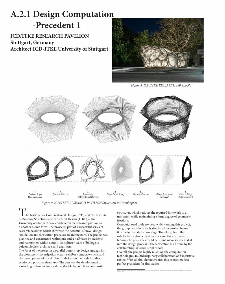
A.2.1 Design Computation -Precedent 1ICD/ITKE RESEARCH PAVILIONStuttgart, GermanyArchitect:ICD-ITKE University of Stuttgart
The Institute for Computational Design (ICD) and the Institute of Building Structures and Structural Design (ITKE) of the University of Stuttgart have constructed the research pavilion in a another bionic form. The project is part of a successful series of research pavilions which showcase the potential of novel design, simulation and fabrication processes in architecture. The project was planned and constructed within one and a half years by students and researchers within a multi-disciplinary team of biologists, paleontologists, architects and engineers.The focus of the project is a parallel bottom-up design strategy for the biomimetic investigation of natural fiber composite shells and the development of novel robotic fabrication methods for fiber reinforced polymer structures. The aim was the development of a winding technique for modular, double layered fiber composite
structures, which reduces the required formwork to a minimum while maintaining a large degree of geometric freedom.Computational tools are used widely among this project, the group used these tools simulated the project before it came to the fabrication stage. Therefore, ‘both the robotic fabrication characteristics and the abstracted biomimetic principles could be simultaneously integrated into the design process.’ 1The fabrication is all done by the collaborating-axis industrial robots.Overall, the project highly relied on the computation technologies, multidisciplinary collaboration and industrial robots. With all this characteristics, this project made a perfect precedent for this studio.
1.JUSTIN MCGAR , COMPUTATIONAL DESIGN: BUILDINGS DESIGNED AND BUILT BY ROBOTS (2014) <HTTP://SOURCEABLE.NET/> [ACCESSED 19 MARCH 2015].
Figure 8. ICD/ITKE RESEARCH PAVILION
Figure 9. ICD/ITKE RESEARCH PAVILION Structural in Grasshopper

A.2.2 Design Computation -Precedent 2LA VOÛTE DE LEFEVRE INSTALLATION
In this project, the rapid, efficient and surface-oriented digital fabrication is used as a modern equivalent of ancient stone carving, marrying the two major architectural parameters – surface and volume. Designed by the New York based Matter Design, the project was preceded by an extensive research dealing with the eco nom i cally friendly sheet mate r ial, while main tain ing a com mon thread of a ded i-ca tion to volume.
The idea of the design of this project has a strong connection with ancient architecture.The design was done by computational tools and the digital fabrication is used as ‘a modern equivalent of ancient stone carving’. This amazing combination ‘marrying the two major architectural parameters – surface and volume’. 1The whole design is so dynamic from top to bottom. The geometry used in this project is irregular but regular. The different hexagons support the whole. Also the form of the project is against most of the buildings in the world - the volume of the superstructure is larger than the foundation. Therefore, with the help of digital computation (and the support ahead), the idea becomes true.
1LIDIJA GROZDANIC, LA VOUTE DE LEFEVRE INSTALLATION INVESTIGATES STEREOTOMIC DESIGN THROUGHDIGITAL FABRICATION (2012) <HTTP://WWW.EVOLO.US/> [ACCESSED 19 MARCH 2015].
Figure 10. LA VOÛTE DE LEFEVRE INSTALLATION
Figure 11. LA VOÛTE DE LEFEVRE INSTALLATION
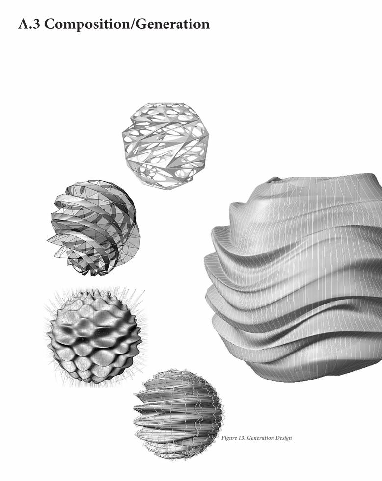
A.3 Composition/Generation
Figure 13. Generation Design

The shift from composition to generation started as the
popularization of digital computation technologies. In this part,
computation technologies are normally operated throughout
software such as grasshopper but not CAD. As I mentioned in the
previous section, computation is different from computerization.
AutoCAD is a typical software for computerization. It
doesn’t generate any new idea based on the existing design.
Computerization only makes existing plan but not develops them.
Differently, software such as Grasshopper would get an item such
as a point, a surface, a solid figure and sort of things as a result
after setting the algorithm.
Architects generate ideas by using these parametric design tools.
And as the developing and maturing of the technology, real-time
rendering enable the architects make new changes to their designs
at any time. So, the design process is becoming totally different
than ever before.
Nonetheless, parametric modelling can’t absolutely replace the
traditional architectural design approach. The models generated
by computer are precise and regular. Inevitably, they are always
monotonous and similar to each other. Possibly, this is the
characteristic of parametric design. Nevertheless, sometimes this
characteristic makes the parametric model can’t fit the context
very well. Many of these designs could be placed into a complete
different context and still ‘looks nice’ itself, but not actually interact
with the environment. Thus, one possible solution is designing
through a more active collaborative work between architect and
parametric modelling specialist. Normally, the architect designs
the project according to the context. If the architect cooperates
with the specialist, they can generate models based on both of the
context and design brief.
To sum up, tParametric design is significant to the architecture
industry as it has redefined the traditional process of create a
building and reformed the structure of the industry.
Computation design is a trend indeed as it has many advantages
that manual work can achieve. In the future, a well combine of
traditional architectural approach and computation design is the
new goal.
The shift from composition to generation has a great influence
on the architectural industry in both positive way and negative
Figure 12. Composition Design

A.3.1 Composition/Generation -Precedent 1LOOM HYPERBOLIC INSTALLATION
“Loom-Hyperbolic” is a site-specific architectural installation that was designed by foreign architects but inspired by local craftsmanship. Created using algorithm-based software programs like Grasshopper and Rhino, the geometric installation is made from structural frames that form 2 dimensional surfaces into 3 dimensional volumes. The frames are made from locally sourced hand-peeled pine poles. Cotton yarn is stretched over these structures to create a gigantic loom composed of thousands of lines.
The aim of this project is to ‘attempting to assume fresh approach to digital fabrication’. This is also a project incorporate modern technologies with traditional techniques which is called ‘Moroccan weaving techniques’ to create the wavy form. The design team used Rhino and Grasshopper to generate this wavy shape on computer. The main structure of this installation is its irregular cellular grid which is inserted into the platform. The parameters of each element of this project is strictly controlled, indeed it seems abnormally but the actually construction ‘translated this irregularity from precise digital design into reality1
1.LIDIJA GROZDANIC, LOOM HYPERBOLIC INSTALLATION / BARKOW LEIBINGER ARCHITECTS (2012) <HTTP://WWW.EVOLO.US/> [ACCESSED 19 MARCH 2015].
Figure 14. LOOM HYPERBOLIC INSTALLATION
Figure 15. Loom HYPERBOLIC installation sketch
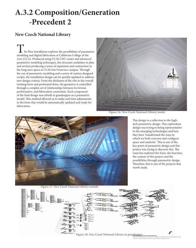
A.3.2 Composition/Generation -Precedent 2New Czech National Library
The Flux Installation explores the possibilities of parametric modeling and digital fabrication at California College of the Arts (CCA). Produced using CCA’s CNC router and advanced parametric modeling techniques, the structure undulates in plan and section producing a sense of expansion and contraction in the long nave space at CCA’s San Francisco campus. Through the use of parametric modeling and a series of custom designed scripts, the installation design can be quickly updated to address new design criteria. From the thickness of the ribs to the overall twisting form and perforated skins, the geometry is controlled through a complex set of relationships between its formal, performative, and fabrication constraints. Each component of the final design was rebuilt in grasshopper as a parametric model. This method allowed us to make real time adjustments to the form that would be automatically updated and ready for fabrication.
This design is a reflection to the high-tech parametric design. This exploration design was trying to being representative to the emerging technologies and how they have ‘transformed the ways in which we both conceive and configure space and material.1 This is one of the key point of parametric design and this project was trying to discover this. The team has explored the form, the function, the context of this project and the possibilities through parametric design. Therefore, this is one of the projects that worth study.
1MATSYS DESIGN, FLUX: ARCHITECTURE IN A PARAMETRIC LANDSCAPE (2009) <HTTP://MATSYSDESIGN.COM/> [ACCESSED 19 MARCH 2015].
Figure 16. New Czech National Library inside.
Figure 17. New Czech National Library outside.
Figure 18. New Czech National Library in grasshopper

A.4 Conclusion

Parametric design is significant to the architecture industry as it has redefined the traditional process of create a building and reformed the structure of the in-dustry.
Computation design is a trend indeed as it has many advantages that manual work can't achieve. In the future, a well combine of traditional architectural approach and computation design is the new goal.
The shift from composition to generation has a great influence on the architectural industry in both positive way and negative way. The models can be generated by the specialists and the computers, however, the architects are
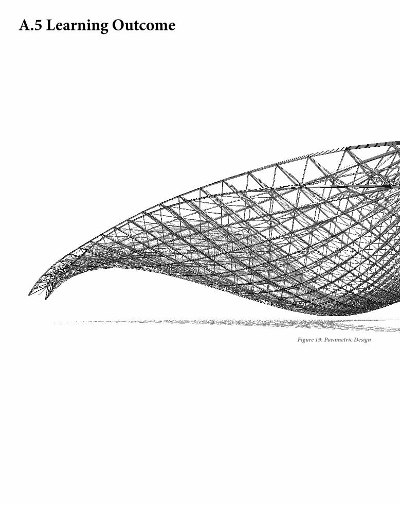
A.5 Learning Outcome
Figure 19. Parametric Design

In the past 2 years, I never used computational modelling software such as Grasshopper to design a project. I always made plan, section and models throughout Rhino, Sketch up, 3DS or computerization software such as AutoCAD. To put it simply, I used to design in traditional architectural approaches. Air studio introduces computation design and parametric design to me. I am really looking forward to making some design throughout grasshopper in Part B and Part C. I enjoy designing. For me, designing in traditional approaches and in computational approach are definitely two different experience. I admire those geometric architecture which was designed throughout parametric approach such as Metropol Parasol. They have strong visual impact and can bring new ideas to me.
I have done Virtual Environment when I was in Year 1. We made an umbrella frame throughout Rhino at that time. I might create more triangle supports into the original frame to improve my old design.
Figure 19. Parametric Design
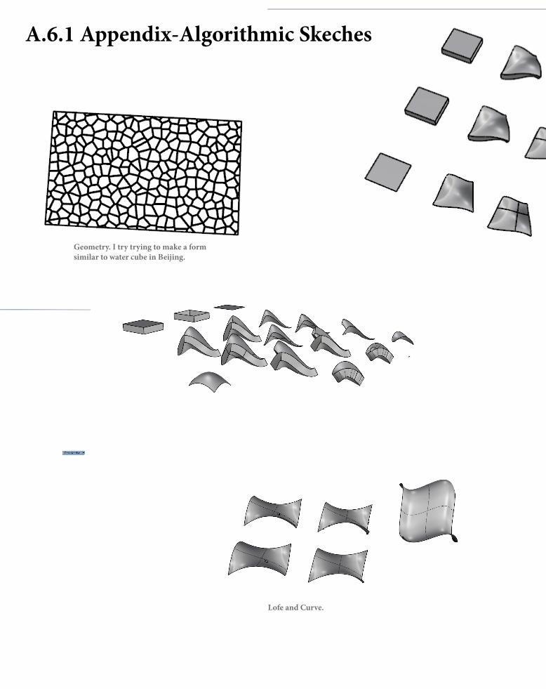
A.6.1 Appendix-Algorithmic Skeches
Geometry. I try trying to make a form similar to water cube in Beijing.
Lofe and Curve.


A.6.2 Appendix-Reference List
Brady Peters, ‘Computation Works: The Building of AlgorithmicThought’, Architectural Design, 83.2, (2013), 08-15.
Justin McGar , Computational Design: Buildings Designed and Built By Robots(2014) <http://sourceable.net/> [accessed 19 March 2015].
LIDIJA GROZDANIC, La Voute de LeFevre Installation Investigates Stereotomic Designthrough Digital Fabrication (2012) <http://www.evolo.us/> [accessed 19 March 2015].
LIDIJA GROZDANIC, Loom Hyperbolic Installation / Barkow Leibinger Architects(2012) <http://www.evolo.us/> [accessed 19 March 2015].
MATSYS DESIGN, FLUX: ARCHITECTURE IN A PARAMETRIC LANDSCAPE(2009) <http://matsysdesign.com/> [accessed 19 March 2015].
Rivka Oxman, Robert Oxman, Theories of the Digital in Architecture,1 edn (London: Routledge, 2014), p. 1-10.

Figure 1. The façade system of Al Bahar Towers, Aedas Architectshttps://www.google.com.au/search?tbm=isch&q=Al+Bahr+Towers+grasshopper&imgrc=Yb3rKdV-pkv4oM%3A&cad=h#imgrc=GT8FMMnai8lfHM%3A
Figure 2. Beijing National Stadium, Pierrede Mueronhttps://www.google.com.au/search?tbm=isch&q=beijing+national+stadium+&imgrc=8ecLuXFoYG7qWM%3A&cad=h
Figure 3. Beijing National Stadium in Grasshopper, Pierrede Mueronhttps://www.google.com.au/search?q=LOOM+HYPERBOLIC+INSTALLATION&biw=1920&bih=911&tbm=isch&tbo=u&source=univ&sa=X&ved=0CBwQsARqFQoTCPGZ09Wcp8cCFaYZpgodsaICTQ#imgrc=aUvcsKyWGgcCaM%3A
Figure 4. The Lotus Temple, Fariborz Sahbahttps://www.google.com.au/search?q=Al+Bahr+Towers&biw=655&bih=551&tbm=isch&tbo=u&source=univ&sa=X&ved=0CBwQsARqFQoTCJ7NzqnDpccCFQbHpgodf4sNbg&dpr=1#tbm=isch&q=lotus+temple+geometry&imgrc=BHJByiZ6CNFqEM%3A
Figure 5. The Lotus Temple plan, Fariborz Sahbahttps://www.google.com.au/search?q=Al+Bahr+Towers&biw=655&bih=551&tbm=isch&tbo=u&source=univ&sa=X&ved=0CBwQsARqFQoTCJ7NzqnDpccCFQbHpgodf4sNbg&dpr=1#tbm=isch&q=lotus+temple+plan&imgrc=rBCa6xPwtXCReM%3A
Figure 6. The Lotus Temple Elevation, Fariborz Sahbahttps://www.google.com.au/search?q=Al+Bahr+Towers&biw=655&bih=551&tbm=isch&tbo=u&source=univ&sa=X&ved=0CBwQsARqFQoTCJ7NzqnDpccCFQbHpgodf4sNbg&dpr=1#tbm=isch&q=lotus+temple+drawing&imgrc=YeRsLNAJO-3nLM%3A
Figure 7. Computation Designhttps://www.google.com.au/search?q=design+computation&tbs=isz:lt,islt:4mp&tbm=isch&imgrc=YTocLE-uuYaKPM%3A&cad=h
Figure 8. ICD/ITKE RESEARCH PAVILIONhttps://www.google.com.au/search?tbm=isch&q=ICD%2FITKE+RESEARCH+PAVILION&imgrc=_WHWWR2z7lfZ3M%3A&cad=h
Figure 9. ICD/ITKE RESEARCH PAVILION Structural in Grasshopperhttps://www.google.com.au/search?tbm=isch&q=ICD%2FITKE+RESEARCH+PAVILION&imgrc=sWsyzL57MC0M8M%3A&cad=h

Figure 10. LA VOÛTE DE LEFEVRE INSTALLATION, Matter Designhttps://www.google.com.au/search?q=LA+VO%C3%9BTE+DE+LEFEVRE+INSTALLATION&biw=1920&bih=911&tbm=isch&tbo=u&source=univ&sa=X&ved=0CCgQsARqFQoTCK2mw6yWp8cCFSbYpgoduyUJUQ#imgrc=UPkBGn1YV_d6TM%3A
Figure 11. LA VOÛTE DE LEFEVRE INSTALLATION, Matter Designhttp://www.evolo.us/wp-content/uploads/2012/07/La-Vo%C3%BBte-de-LeFevre-Installation-6.jpg
Figure 12. Composition Designhttps://www.google.com.au/search?biw=1920&bih=955&tbs=isz%3Al&tbm=isch&sa=1&q=algorithmic+design&oq=algorithmic+design&gs_l=img.3...36241.40132.0.40541.19.13.0.0.0.1.853.1619.6-2.2.0....0...1c.1j4.64.img..18.1.765.MIvgwb18y1U#imgrc=fAmPrg88l_dqbM%3A
Figure 13. Generation Designhttps://www.google.com.au/search?biw=1920&bih=955&tbs=isz%3Al&tbm=isch&sa=1&q=algorithmic+design&oq=algorithmic+design&gs_l=img.3...36241.40132.0.40541.19.13.0.0.0.1.853.1619.6-2.2.0....0...1c.1j4.64.img..18.1.765.MIvgwb18y1U#imgrc=j3Cm6YCYyXhheM%3A
Figure 14. LOOM HYPERBOLIC INSTALLATION, Barkow Leibingerhttps://www.google.com.au/search?q=LOOM+HYPERBOLIC+INSTALLATION&biw=1920&bih=911&tbm=isch&tbo=u&source=univ&sa=X&ved=0CBwQsARqFQoTCPGZ09Wcp8cCFaYZpgodsaICTQ#imgrc=oBQ1iLX3afNImM%3A
Figure 15. LOOM HYPERBOLIC INSTALLATION Sketchhttps://www.google.com.au/search?q=LOOM+HYPERBOLIC+INSTALLATION&biw=1920&bih=911&tbm=isch&tbo=u&source=univ&sa=X&ved=0CBwQsARqFQoTCPGZ09Wcp8cCFaYZpgodsaICTQ#imgrc=aUvcsKyWGgcCaM%3A
Figure 16. New Czech National Library inside, New Czech National Library
Figure 17. New Czech National Library outside, New Czech National Libraryhttp://www.otaplus.com/wp-content/uploads/2011/12/Flux_14.jpg
Figure 18. New Czech National Library in grasshopper


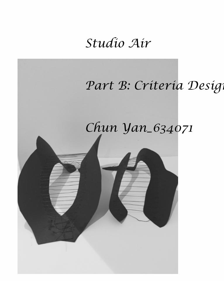
Studio Air
Part B: Criteria Design
Chun Yan_634071
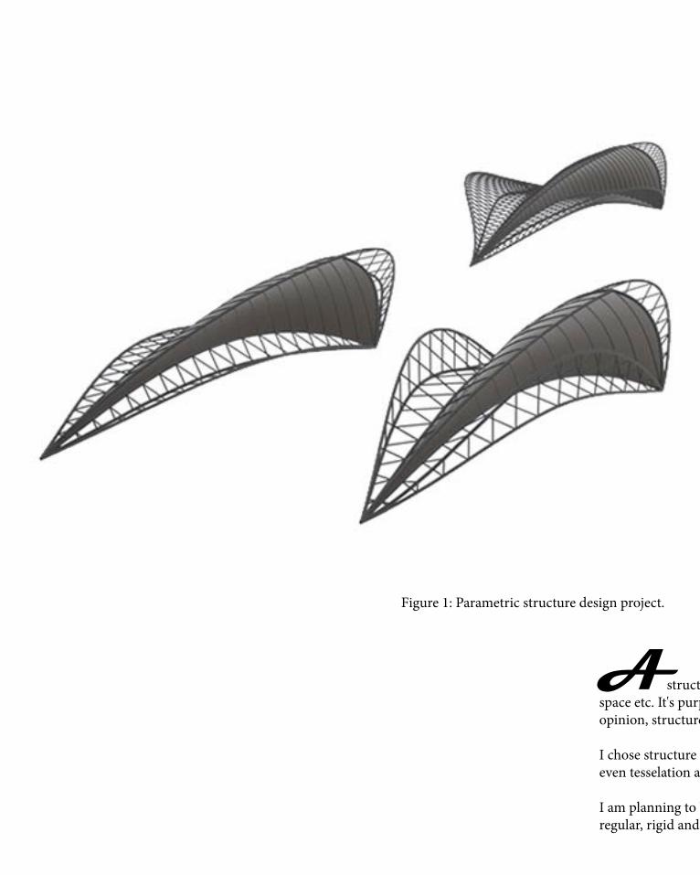
A structure is loosely defined as a physical object, or a system therof, that enables people crossing voids, lift goods, define space etc. It's purpose of function is to supply the strength, stiffness, and ragidity to fullfill the aforementionaed functions. In my opinion, structure is a general term. Everthing is built based on a structure form, and every existent form could be a kind of structure.
I chose structure as my design brief because I think it has the most opportunities and potentials. Geometry, section biomimicry and even tesselation are formed based on their unique structure.
I am planning to buiild a changeable and flexible project based on the idea of structure. Normally, structure gives people a sense of regular, rigid and expressive, which are mostly demonstrated as lattice, waffle and column grids.
Figure 1: Parametric structure design project.
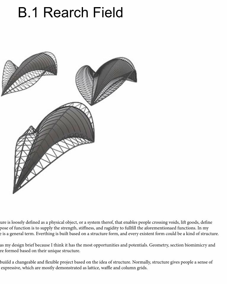
B.1 Rearch Field
A structure is loosely defined as a physical object, or a system therof, that enables people crossing voids, lift goods, define space etc. It's purpose of function is to supply the strength, stiffness, and ragidity to fullfill the aforementionaed functions. In my opinion, structure is a general term. Everthing is built based on a structure form, and every existent form could be a kind of structure.
I chose structure as my design brief because I think it has the most opportunities and potentials. Geometry, section biomimicry and even tesselation are formed based on their unique structure.
I am planning to buiild a changeable and flexible project based on the idea of structure. Normally, structure gives people a sense of regular, rigid and expressive, which are mostly demonstrated as lattice, waffle and column grids.
Figure 1: Parametric structure design project.

Case Study 1-1

The canopy is constructed of vertical laminated wood plates following a 1.5 by 1.5 cutting pattern. The assembled plates thus form a grid structure, a grillage. For safety reasons the restaurant is situated on a composite steel platform. The wood plates have been sprayed with a polyurethane coating and painted in an ivory white shade which visually brings the individual pieces together. It also results in the peculiar effect that the structure appears simultaneously as a built in-scale construction as well as an over-size model. This ambiguity between form, image, and structure is further emphasized by the fact that the construction has not been covered but is laid bare; this accentuates the contrast between the repetitious pattern of the grid and the winding shape of the canopy.
The structure forms a new gathering point in Seville: A place for interaction, in which ancient is connected with present, earth with sky. The grid structure, extensively used by the Romans for urban layouts, is here transformed and contrasted by the curving shapes of the canopy. Further movement is suggested between points, lines, and surfaces: From the nodes formed by the 'trunks' to the meandering outline of the canopy to the imaginary surfaces created by the grillage. A play between what is revealed and what is not, between virtual and actual.

The Stadium is a massive and an incredibly complicated structure. The structural design was introduced by the Herzog & De Meuron, whom from very initial stages have been working with structural engineers from Ove Arup & Partners and developing 3D models.
Because the proposed structure was so complicated, in order to sell the idea even the smaller detail had to be thought of and modeled in the very early stages of the project.
The detail above shows one f numerous connections involved in the structure. Due to such significant loads on the structure members as well as their connections had to be designed carefully. the welding process alone sometimes took 17 hours per connection with several welders switching places to avoid exhaustion.
Developing structural calculations for this building would be incredibly rewarding and fun, but it would also be very challenging. even though computer software can be used, some hand calculations should be done to verify the results. below is a partial structural plan of roof framing for the stadium indicating the grid used to determine the geometry of the “Nest”.
Figure 2: The structure of the bird nest stadium.
Case Study 1-2
National statiumBeijingBird Nestenormous saddle-shaped elliptic steel structure
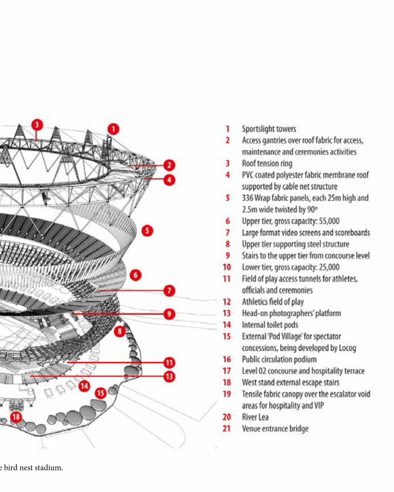
Figure 2: The structure of the bird nest stadium.

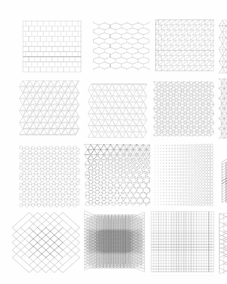
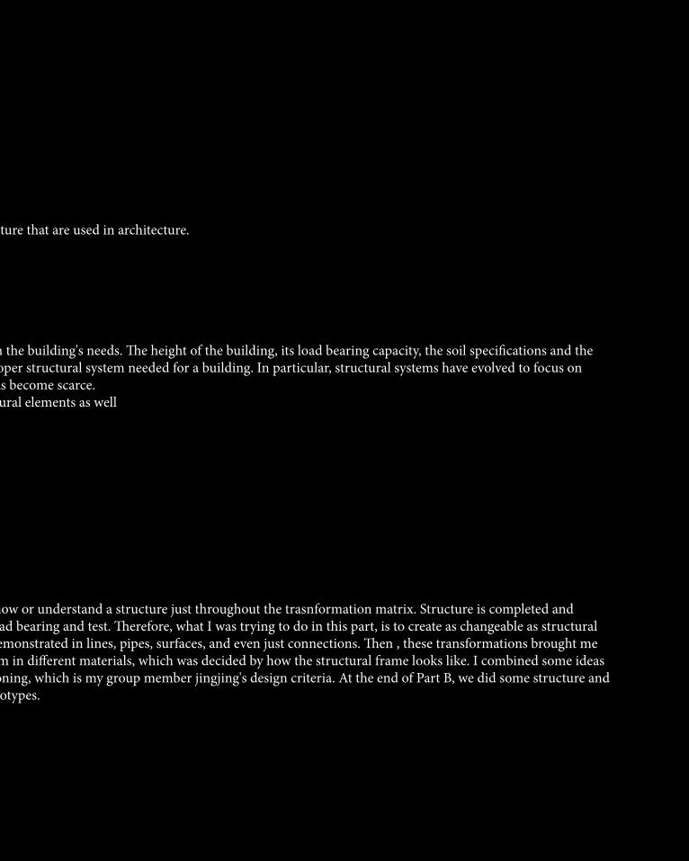
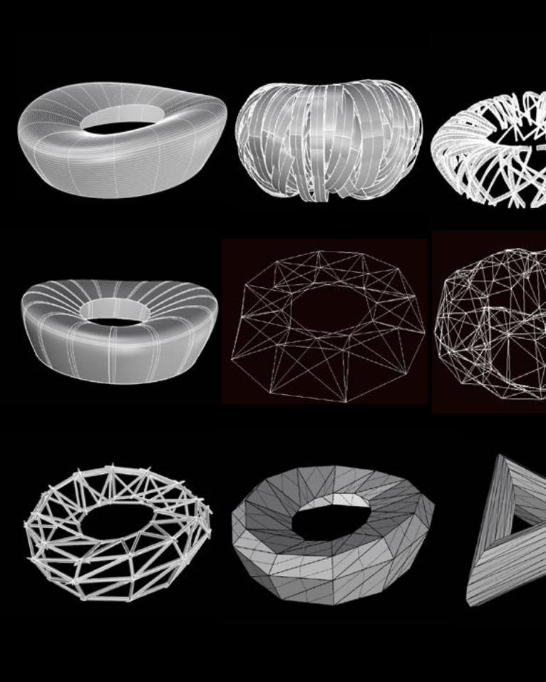
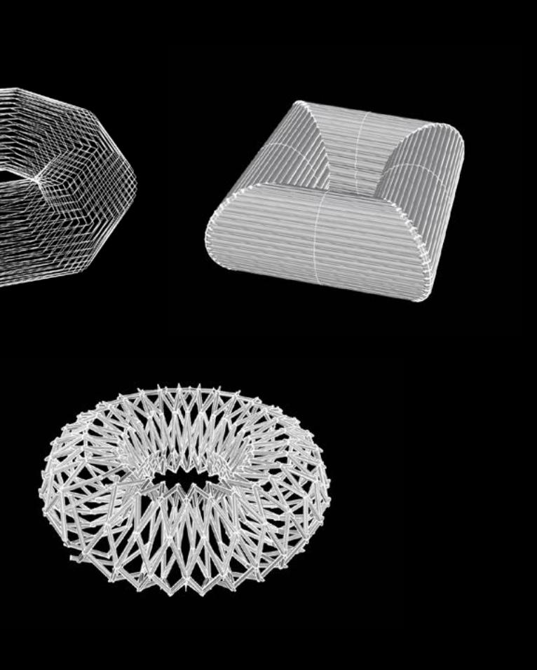
In Case Study 1.0, I used lunchbox to generate the transformation matrix throughout lunchbox plugin. The original shape of these 30 transformations is just a simple square. The main purposes that I planned to achieve and test during the process is I want to create different structure pattern firstly in 2D perspectives which can bring me a inspiration of the material that can be used to create a structure form. Sometimes, the structure is built based on the material. For example, bricks and reinforcing steel generate differet type of structure which need different force analysis. Another purpose is that i want to test the availability of different structure form. During the process that i tried to create structure pattherns i see some structure frame look stable and are valuable to do a further development. However, some of them are not a successful structure because they even didn't have connections with each other. In these 30 structural frames and patterns transformations, some of them are created by line, some of them are created by slides and some of them are created by surfaces. I imagine these as steel columns, wood chip and metal sheet. Some of them looks feasiible but some are not. I chose some of them to make a prototype to test its availability.

B.2 Case Study 1.0
In Case Study 1.0, I used lunchbox to generate the transformation matrix throughout lunchbox plugin. The original shape of these 30 transformations is just a simple square. The main purposes that I planned to achieve and test during the process is I want to create different structure pattern firstly in 2D perspectives which can bring me a inspiration of the material that can be used to create a structure form. Sometimes, the structure is built based on the material. For example, bricks and reinforcing steel generate differet type of structure which need different force analysis. Another purpose is that i want to test the availability of different structure form. During the process that i tried to create structure pattherns i see some structure frame look stable and are valuable to do a further development. However, some of them are not a successful structure because they even didn't have connections with each other. In these 30 structural frames and patterns transformations, some of them are created by line, some of them are created by slides and some of them are created by surfaces. I imagine these as steel columns, wood chip and metal sheet. Some of them looks feasiible but some are not. I chose some of them to make a prototype to test its availability.

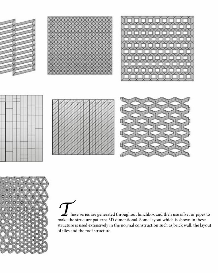
These series are generated throughout lunchbox and then use offset or pipes to make the structure patterns 3D dimentional. Some layout which is shown in these structure is used extensively in the normal construction such as brick wall, the layout of tiles and the roof structure.
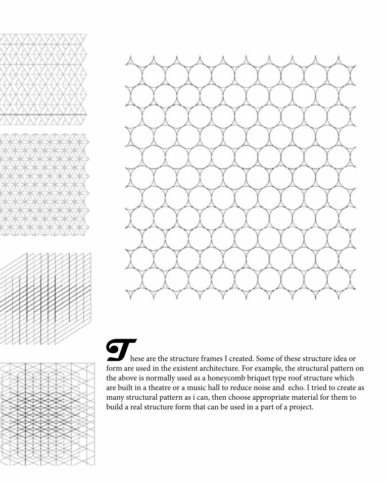
These are the structure frames I created. Some of these structure idea or form are used in the existent architecture. For example, the structural pattern on the above is normally used as a honeycomb briquet type roof structure which are built in a theatre or a music hall to reduce noise and echo. I tried to create as many structural pattern as i can, then choose appropriate material for them to build a real structure form that can be used in a part of a project.

Load ResistanceThe Beijing National Stadium is designed to resist both typical building loads and earthquake loads.
Horizontal Loads
The structure must resist a total of 56,625 tons of vertical load. The Steel structure itself must resist its own load of 42,000 tons and 11,625 tons of live load, totaling in 53,625 tons. The Plinth type of the foundation is essential to carry such a load, which is fairily evenly distributed.
Each member of the steel “Nest” is designed carefully to carry its own weight of 42, 000 tons loads. The overall shape appears to be random, but in reality it follows strict geometric rules. Figure 3; The loads at each intersection of Beijing National Statium.
The loads at each intersection are split between the members and transferred downward as indicated above.
The red points indicate the transfer connections were load impact is felt most significantly. The below image identifies the primary and secondary members. the secondary members had to be welded on two sides of primary members. The steel envelope is constructed of 22.5 miles of steel and it took about 700 welders to complete the task.
B.3 Case Study 2.0National statiumBeijingBird Nestenormous saddle-shaped elliptic steel structure

Lateral Loads
The massive steel structure resists lateral loads in a similar manner as the horizontal ones. In addition, instead of the loads hitting the structure and following it downwards and upwards it is broken down through the lattice of steel while being weakened and providing natural ventilation in the building.
The core portion of the building carries the dead load of the concrete structure as well as the live load of people totaling to 13,122 tons. The load is transferred directly to the plinth foundation as distributed load as shown on the left.
Earthquake Loads
The Beijing National Stadium was designed with earthquake loads in mind, because Beijing is prone to seismic events. The outer steel structure is completely separate from the inner stadium seating area and is placed 50 feet apart. this placement allows the two structures move independently in case of an earthquake. Steel has a rather high modulus of elasticity as compared to the concrete, therefore the entire outer structure could be put together as a unit and withstand earthquakes. The core of the stadium was constructed out of the pre-cast reinforced concrete. Because concrete has significantly lower modulus of elasticity, it was decided into eight individual sections. this division allows each portion of structure to move independently of the other in case of seismic motion causing minimal amount of damage. Beijing Bird’s Nest is designed to withstand earthquakes rated at 8.0 on Richter Scale
Figure 4; How vertical loads work at Beijing National Statium.
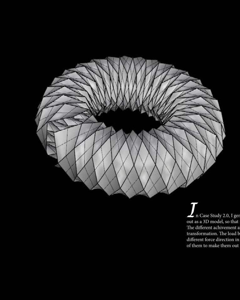
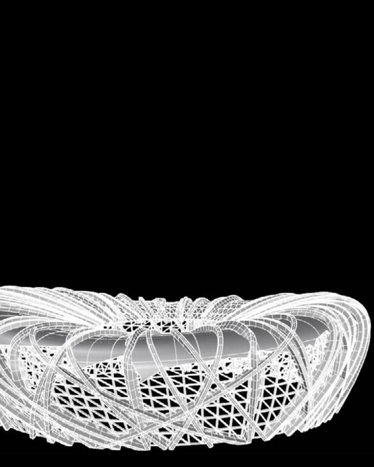
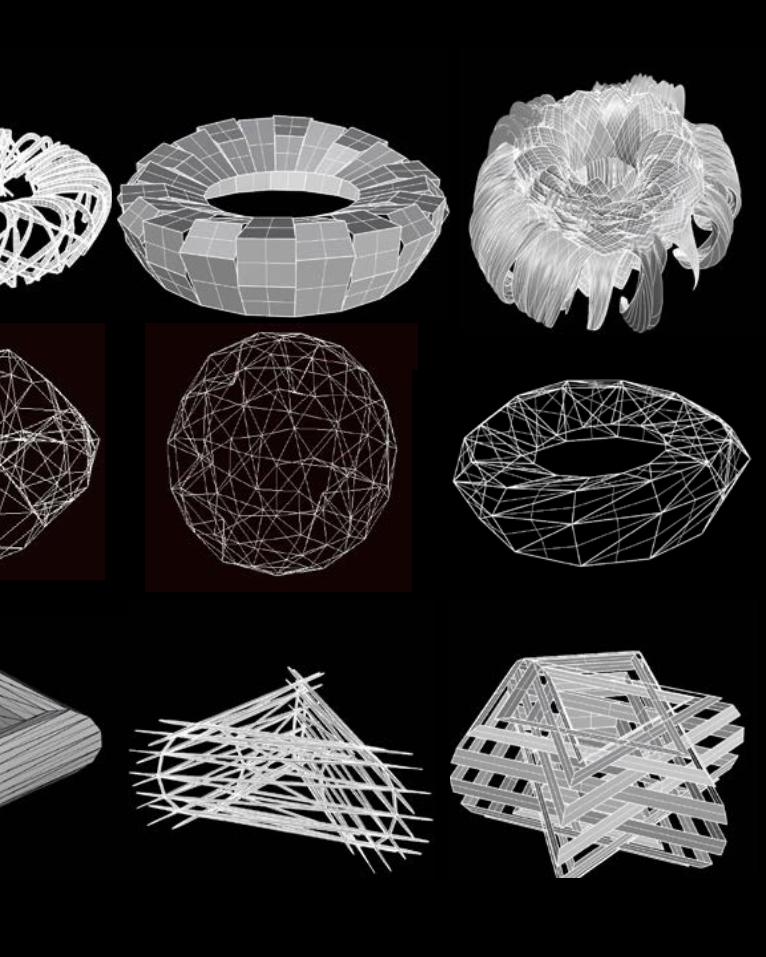
In Case Study 2.0, I generated the basic surface of the bird nest stadium. I want to create different structure pattern and frame and made it out as a 3D model, so that it will be easier to analyze the load, the connection and the support and resistant force in each structural form.The different achivement and test between case study 1 and 2 is that case study 1 is a 2D perspective structure while case study 2 is a 3D model transformation. The load bearing is essential to be considered. So in the 50 transformations in case study 2, I expected analyze and test the different force direction in different structure form. After create these 3D perspective transformations, I planned to choose some typical model of them to make them out throughout appropriate material.

In Case Study 2.0, I generated the basic surface of the bird nest stadium. I want to create different structure pattern and frame and made it out as a 3D model, so that it will be easier to analyze the load, the connection and the support and resistant force in each structural form.The different achivement and test between case study 1 and 2 is that case study 1 is a 2D perspective structure while case study 2 is a 3D model transformation. The load bearing is essential to be considered. So in the 50 transformations in case study 2, I expected analyze and test the different force direction in different structure form. After create these 3D perspective transformations, I planned to choose some typical model of them to make them out throughout appropriate material.
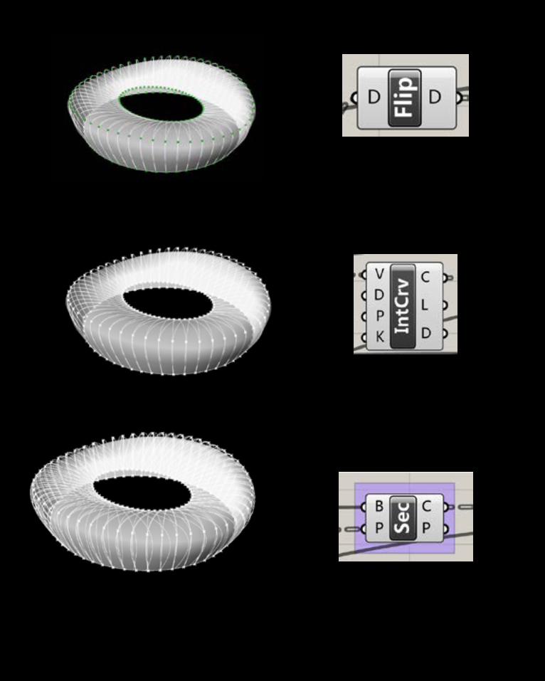
B.4 Technique development
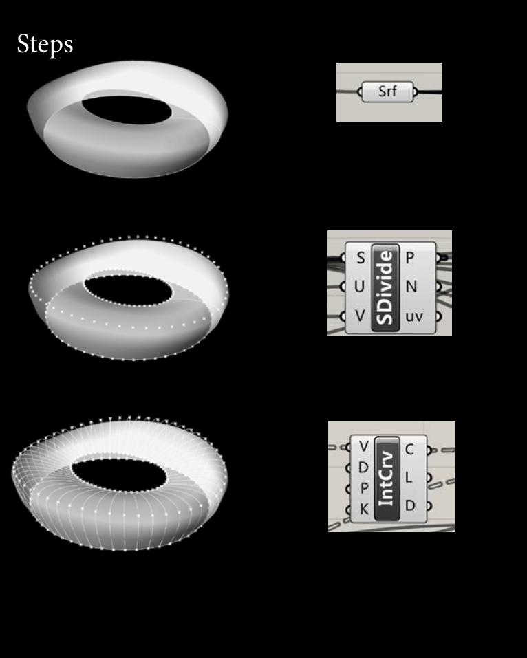
Start by defining a central points inGH. Then generate the
Steps


There are many types of structure that are used in architecture.1)Rock and Stone2) Wood Frame3) Steel Truss and Frame4) Precast Concrete5) Reinforced Concrete6) Prestressed ConcreteThe type of system used depends on the building's needs. The height of the building, its load bearing capacity, the soil specifications and the building materials all dictate the proper structural system needed for a building. In particular, structural systems have evolved to focus on building up as undeveloped land has become scarce.Also, there are many types of structural elements as wellStructural System Elementsa) Beam and Columnb) Framec) Trussd) Arche) Wall and Platef) Cylindrical Shell and Vaultg) Spherical Shell and Domeh) Cable and Rodi)Membrane Tent and Net
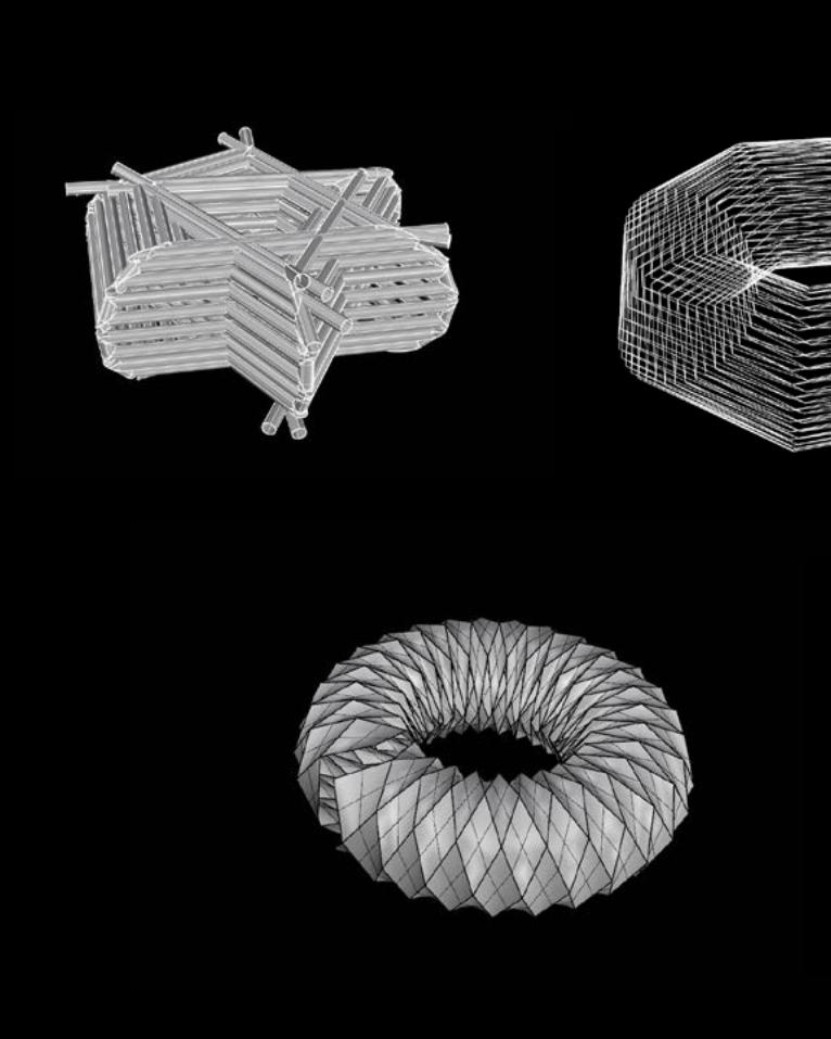
In my opinion, it is impossible to show or understand a structure just throughout the trasnformation matrix. Structure is completed and developed only by analysis of the load bearing and test. Therefore, what I was trying to do in this part, is to create as changeable as structural type frame or patthern which are demonstrated in lines, pipes, surfaces, and even just connections. Then , these transformations brought me inspirations to build a structure form in different materials, which was decided by how the structural frame looks like. I combined some ideas from my transformation with sectioning, which is my group member jingjing's design criteria. At the end of Part B, we did some structure and landscape test throughtout our prototypes.
There are many types of structure that are used in architecture.1)Rock and Stone2) Wood Frame3) Steel Truss and Frame4) Precast Concrete5) Reinforced Concrete6) Prestressed ConcreteThe type of system used depends on the building's needs. The height of the building, its load bearing capacity, the soil specifications and the building materials all dictate the proper structural system needed for a building. In particular, structural systems have evolved to focus on building up as undeveloped land has become scarce.Also, there are many types of structural elements as wellStructural System Elementsa) Beam and Columnb) Framec) Trussd) Arche) Wall and Platef) Cylindrical Shell and Vaultg) Spherical Shell and Domeh) Cable and Rodi)Membrane Tent and Net
In my opinion, it is impossible to show or understand a structure just throughout the trasnformation matrix. Structure is completed and developed only by analysis of the load bearing and test. Therefore, what I was trying to do in this part, is to create as changeable as structural type frame or patthern which are demonstrated in lines, pipes, surfaces, and even just connections. Then , these transformations brought me inspirations to build a structure form in different materials, which was decided by how the structural frame looks like. I combined some ideas from my transformation with sectioning, which is my group member jingjing's design criteria. At the end of Part B, we did some structure and landscape test throughtout our prototypes.


SITE ANALYSIS
We chose a flat space near the merri creek primary school as our site location. This area has extravagant vegetation. We planned to create a project which can collect fallen leaves and plants. These space has a lot of withering plants which need to be cleanning. Our design purpose is to make a good use of these withering plants and reduce the pressure of cleanning.
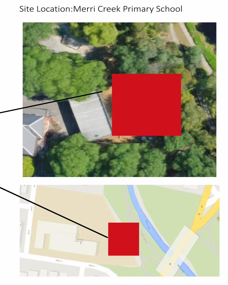
Site Location:Merri Creek Primary School
We chose a flat space near the merri creek primary school as our site location. This area has extravagant vegetation. We planned to create a project which can collect fallen leaves and plants. These space has a lot of withering plants which need to be cleanning. Our design purpose is to make a good use of these withering plants and reduce the pressure of cleanning.

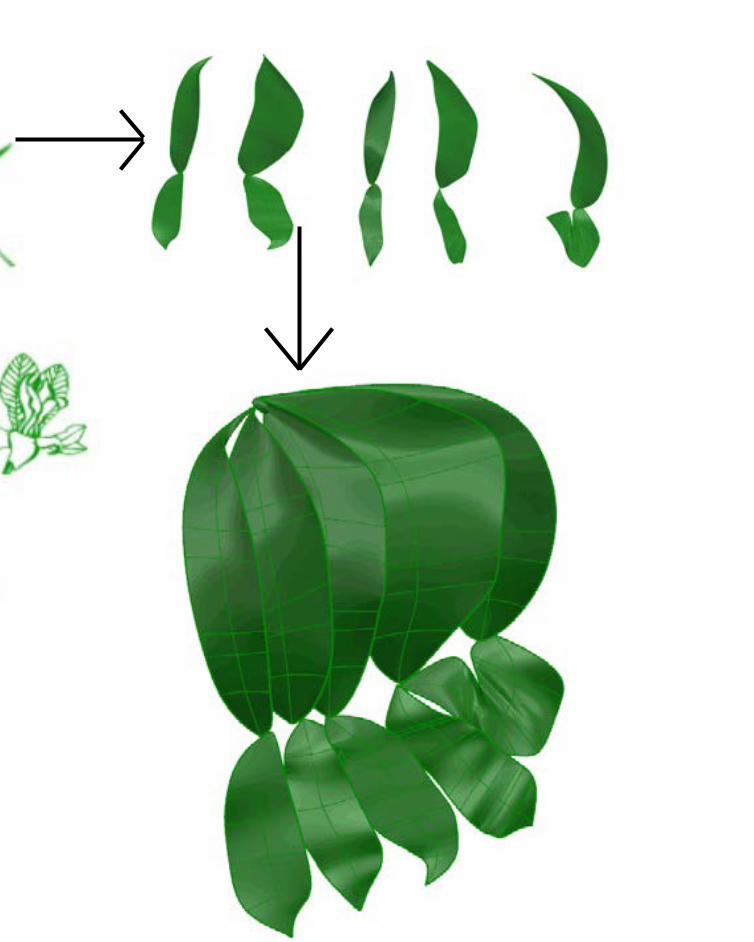
Design Inspiration
Our original inspiration comes from the shape of the leaf. The leaf appears the most in the site. Also, leaf is a part of our design brief. We were thinking about combine this shape with our design criteria, structure and section.
Design opportunity:During the site visit we discovered that the primary school student, especially children in the early age want to get in touch with the plants along the river. However their behaviour may destory the nature and the education from school are not allow them to do that. Therefore, our design will give the opptunity to get in touch with the nature.
The purpose of the designto allow chirldren to get in touch with the nature and also provide a place for the climbers (plants) growing
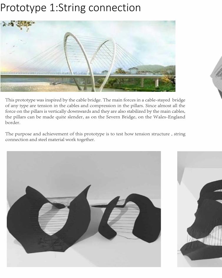
Prototype 1:String connection
This prototype was inspired by the cable bridge. The main forces in a cable-stayed bridge of any type are tension in the cables and compression in the pillars. Since almost all the force on the pillars is vertically downwards and they are also stabilized by the main cables, the pillars can be made quite slender, as on the Severn Bridge, on the Wales-England border.
The purpose and achievement of this prototype is to test how tension structure , string connection and steel material work together.


Prototype 2:Waffle connection This prototype was inspired by the strucuture of Metropol Parasol. Metropol’s interweaving waffle-like wooden panels rise from concrete base reinforced with steel, which are positioned in such a way to architecturally form canopies and walkways below the parasols.
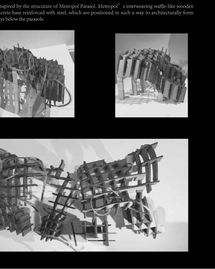
This prototype was inspired by the strucuture of Metropol Parasol. Metropol’s interweaving waffle-like wooden panels rise from concrete base reinforced with steel, which are positioned in such a way to architecturally form canopies and walkways below the parasols.
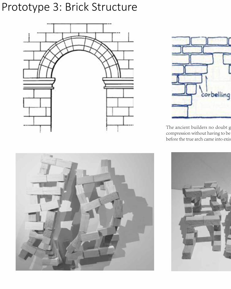
Prototype 3: Brick Structure
The ancient builders no doubt gave a great deal of thought to how they could utilize the great strength of stone and brick in compression without having to be limited by its very small strength in tension. The arch is a satisfactory solution to this prob lem, but before the true arch came into existence it was probably preceded by preliminary intuitive attempts as depicted in Fig. 4.2
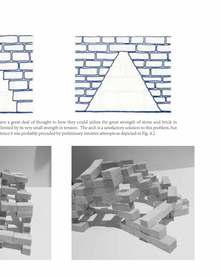
The ancient builders no doubt gave a great deal of thought to how they could utilize the great strength of stone and brick in compression without having to be limited by its very small strength in tension. The arch is a satisfactory solution to this prob lem, but before the true arch came into existence it was probably preceded by preliminary intuitive attempts as depicted in Fig. 4.2

Prototype 4
This prototype came from the combination of the idea of sectioning and structure. It tested the verticle load and appearence of the design. In this stage, we tried a different structure of vertical 'overlap-type structure design.
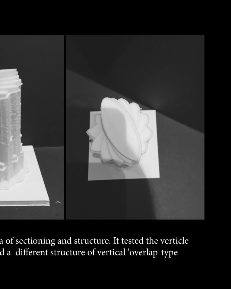
This prototype came from the combination of the idea of sectioning and structure. It tested the verticle load and appearence of the design. In this stage, we tried a different structure of vertical 'overlap-type structure design.


Part C-DETAILED DESIGN


Part C-DETAILED DESIGN
-C.1 Design Concept
C.1 Design Concept
Response to feedbacks -Directions
-Site Specified & Functions.
our original function was to provide more opportunities for the childrean from merri
creek primary schoolto get in touch with the nature and also provide a place for the
climbers (plants) to grow. Instead of providing a space for climbers, the current main part is
designing a recreational place for the children especially students under year three.
-Structure
The structure of the project is extended from our most sucessful prototype in Part B which
is tension. The shape and the boundary of the project is designed based on the location and
the height of the trees on site.
-Purpose & Significance
The previous purpose of the design is to provide a place for the children to touch and
feel the plants on the side of the merri creek. According to the feedback, the purpose was
developed to attract the children to the riverside and provide a recreational place for them
to have a better experience while enjoying the environments. Trees on the two sides of
the merri Creek didn't only decide the boundary of the design, but also play a role of 'tree
canopy', which provide natural shaow for users.
Response to feedbacks -Method & Changes
-Site Specified & Functions
The site location didn't change, because the audience are still primary school students.
The usage for the audience was changed from the 'get in touch with plants' to 'enjoy the
environments with the family.
-Structure
We tried many structures in Part B and spent the most time to do the 'waffle' prototype,
which we think is the most sucessful one. Along with the change of the function, the main
structure of our design was changed from 'waffle' to tension.
-Purpose & Significance
The original purpose and the significance of our design is to lead the children to know more
and experience more about the nature and the environments. According to the feedback,
that was developed to create a open space for the children and their family to go to enjoy
the nature after school.
Previous Design Proposal
Lcation-A flat space near the merri creek primary school was chosen as our site location as there are extravagant vegetation there, which associate with the function and the purpose of the design project.
Method-The previous design Focused too much on how to let the climbers (plants) attach to the design. In other words, waffle, geometry, grid and sort of elements much be used in the design to achieve the original function.
Design Potential-We planned to create a project which can collect fallen leaves and plants. The previous design purpose is to make a good use of these withering plants and reduce the pressure of cleanning
C.1 Design Concept

Final Design Proposal
To bring a sense of viability back to the sitein contrast to the surrounding built form
To engage the users with the naturallandscape,particularly the Merri Creek byenabling physical interaction with the site
To become a iconic landscape along MerriCreek and accommodate social activities topromote visbility and sense of community inthis area

C.1 Design ConceptC.1 Design Concept
A bridge-style recreational open place for students from Merri Creek primary school and their family to enjoy the natural environments by the merri creek. The users have to make a one-way walk and the trees on the two sids of the merri creek have provided a natural tree canopy for users on the project.

A bridge-style recreational open place for students from Merri Creek primary school and their family to enjoy the natural environments by the merri creek. The users have to make a one-way walk and the trees on the two sids of the merri creek have provided a natural tree canopy for users on the project.

C.1 Design Concept
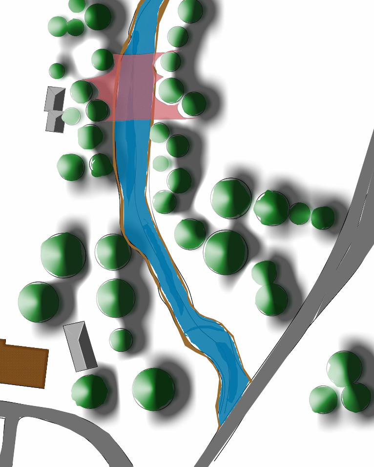
The two sides of the Merri Creek are along with two rows of trees respectively. On the site of our design, the diameter of the biggest one is approximately 1 meter, and the diameter of the finest one is about 0.5 meter. All of them have flourishing branches and trunk, which is suitable to be a canopy and provide the shadow.
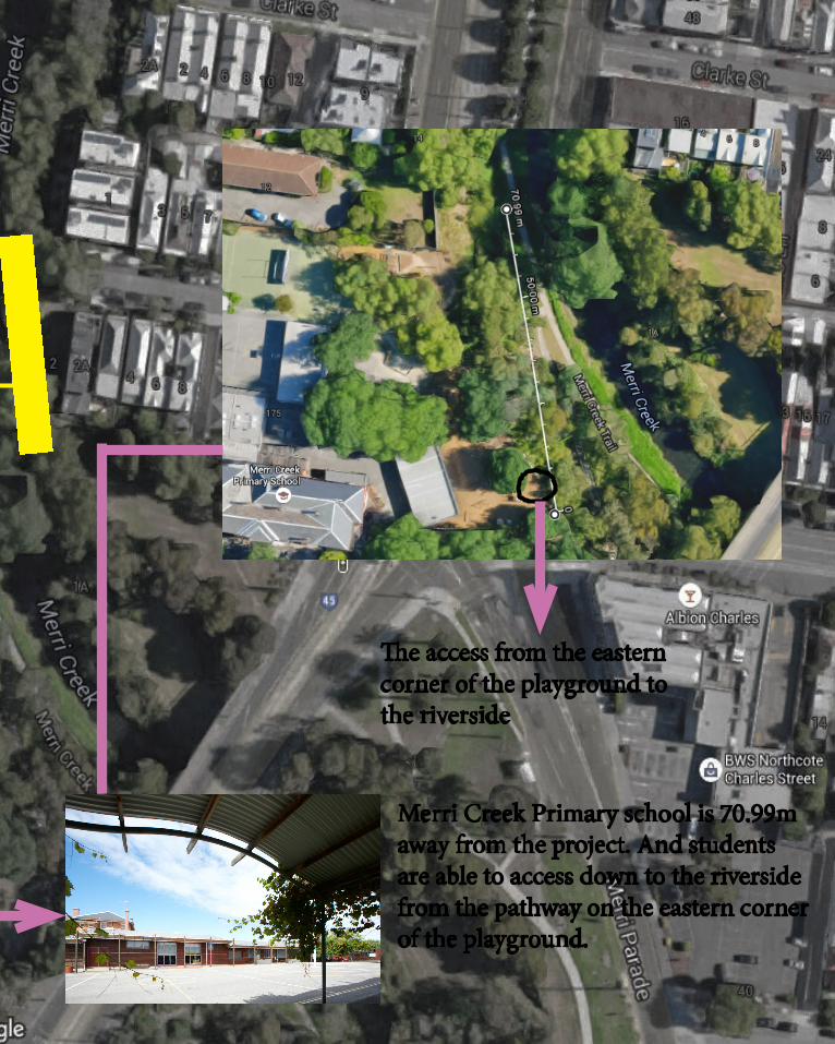
Merri Creek Primary school is 70.99m away from the project. And students are able to access down to the riverside from the pathway on the eastern corner of the playground.
The access from the eastern corner of the playground to the riverside

diameter:100cm
diameter:50cm
diameter:60cm
diameter:60cm
diameter:40cm
diameter:70cm
C.1 Design Concept
The pink part is the location of our design.
The boundary of the project skirt the existing trees on both sides of the yarra river and form to the final shape. Also, The trees closely around the project provide a natural canopy for users. The project will aross the river and pathway on the both side of the river.It could ensure the chirldren directly get into the jungle from oneside to the otherside such us a tree bridge.
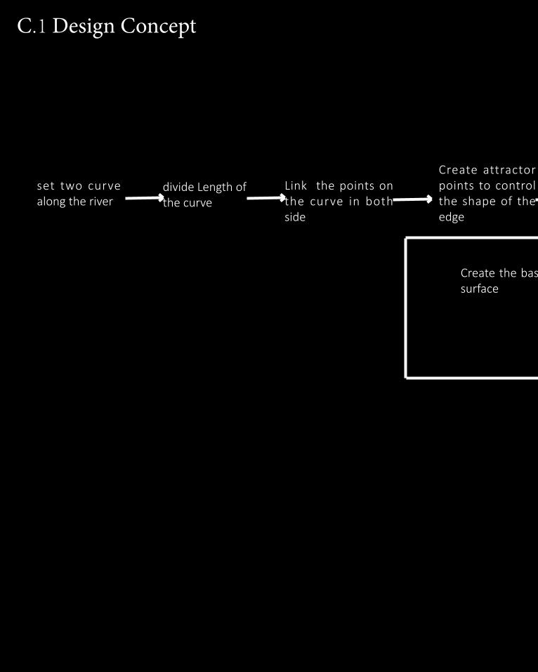
divide Length of the curve
Link the points on the curve in both side
Create attractor points to control the shape of the edge
Create the basement surface
C.1 Design Concept
set two curve along the river
Create the basement surface
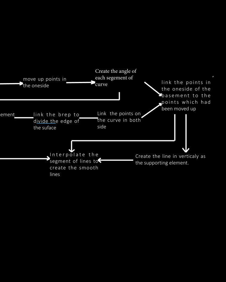
l i n k t h e b r e p t o divide the edge of the suface
Link the points on the curve in both side
move up points in the oneside l i n k t h e p o i nt s i n
the oneside of the b a s e m e n t t o t h e p o i n t s w h i c h h a d been moved up
Create the line in verticaly as the supporting element.
I n t e r p o l a t e t h e segment of lines to create the smooth lines
Create the angle of each segement of curve

C.1 Design Concept


Part C-DETAILED DESIGN
-C.2 Tectonic Elements & Prototypes
C.2 Tectonic Elements & Prototypes-Prototype-1
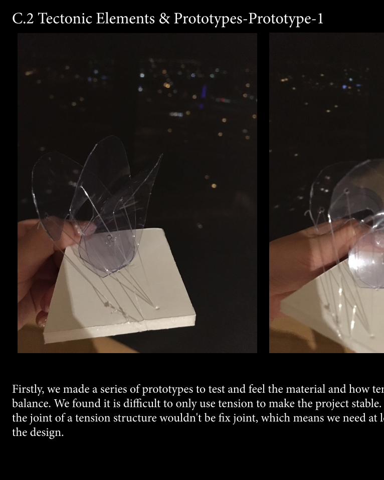
Firstly, we made a series of prototypes to test and feel the material and how tension works to make the project keep balance. We found it is difficult to only use tension to make the project stable. Tension is a kind of fluid force. Always, the joint of a tension structure wouldn't be fix joint, which means we need at least one another joints to suport and fix the design.

Firstly, we made a series of prototypes to test and feel the material and how tension works to make the project keep balance. We found it is difficult to only use tension to make the project stable. Tension is a kind of fluid force. Always, the joint of a tension structure wouldn't be fix joint, which means we need at least one another joints to suport and fix the design.
C.2 Tectonic Elements & Prototypes-Prototype-2
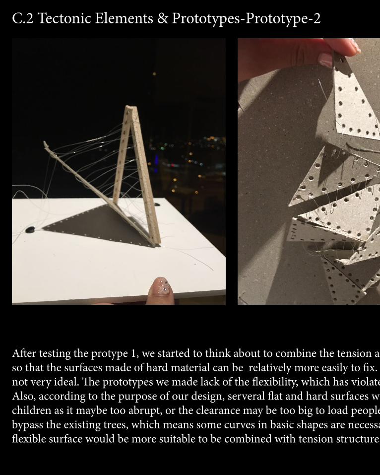
After testing the protype 1, we started to think about to combine the tension and the surface with high hardness so that the surfaces made of hard material can be relatively more easily to fix. However, the consequence was not very ideal. The prototypes we made lack of the flexibility, which has violated our original idea from Part B. Also, according to the purpose of our design, serveral flat and hard surfaces was not suitable to form a place for children as it maybe too abrupt, or the clearance may be too big to load people. In addition, our design need to bypass the existing trees, which means some curves in basic shapes are necessary. For that reason, we think a flexible surface would be more suitable to be combined with tension structure.
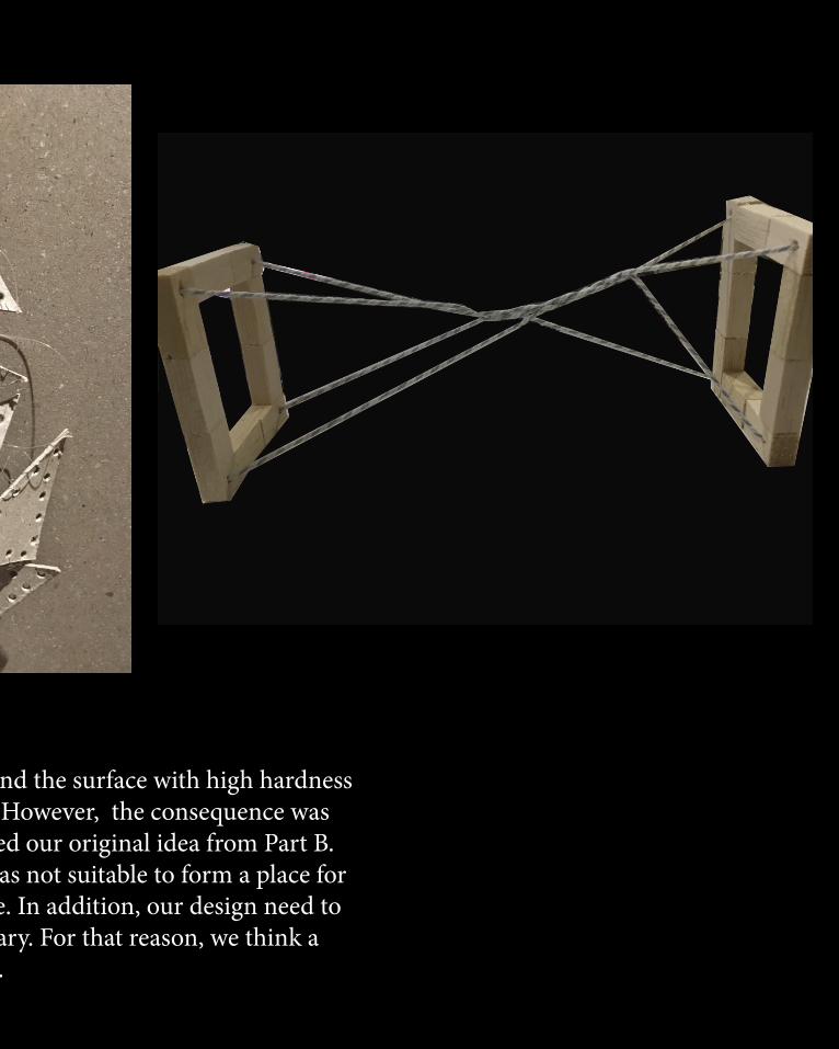
After testing the protype 1, we started to think about to combine the tension and the surface with high hardness so that the surfaces made of hard material can be relatively more easily to fix. However, the consequence was not very ideal. The prototypes we made lack of the flexibility, which has violated our original idea from Part B. Also, according to the purpose of our design, serveral flat and hard surfaces was not suitable to form a place for children as it maybe too abrupt, or the clearance may be too big to load people. In addition, our design need to bypass the existing trees, which means some curves in basic shapes are necessary. For that reason, we think a flexible surface would be more suitable to be combined with tension structure.

C.2 Tectonic Elements & Prototypes-Prototype-3
After deciding our model direction and components, we made this prototype. We found that it is possible to only use cable to support the design, when the material of the surface have enough elasticity and toughness. however, one side of the surface must be fixed. the shape of the design can be changed by cables in tension structure.


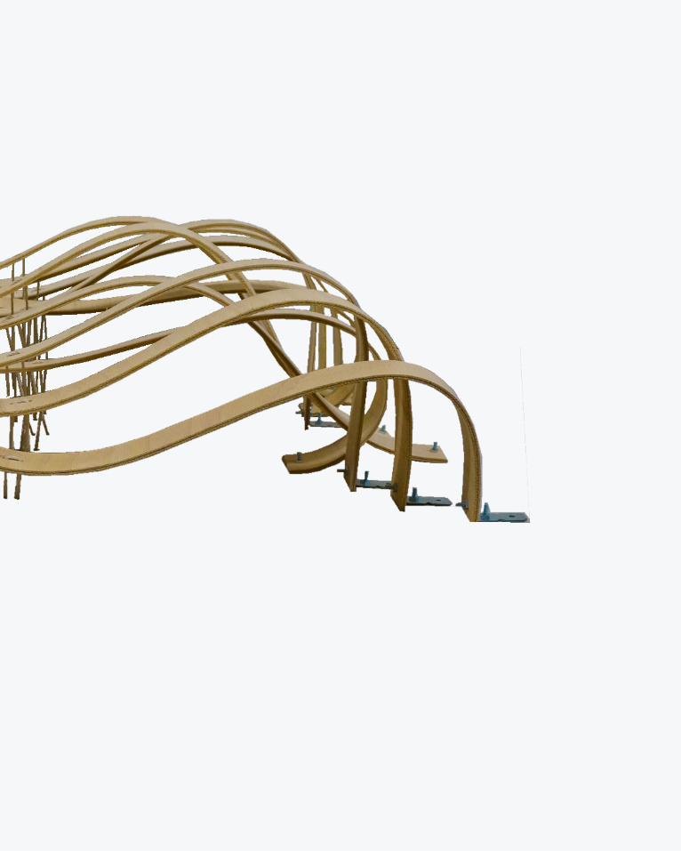
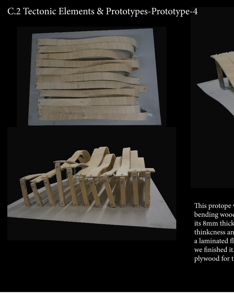
C.2 Tectonic Elements & Prototypes-Prototype-4
C.2 Tectonic Elements & Prototypes-Prototype-4
This protope was done after we have finished our final model. Actually this material-bending wood, were originally chosen as the material for our final model. However, due to its 8mm thickness, the fablab can't do it in laser cut, so we completely did it by hand. The thinkcness and the flexibility of the material is perfect for our design. The advantage is, as a laminated flexible timber wood, it seems too soft. the whole project kept shaking while we finished it. Finally, we still decide to use the perspex as the material for the strips, and plywood for the columns.
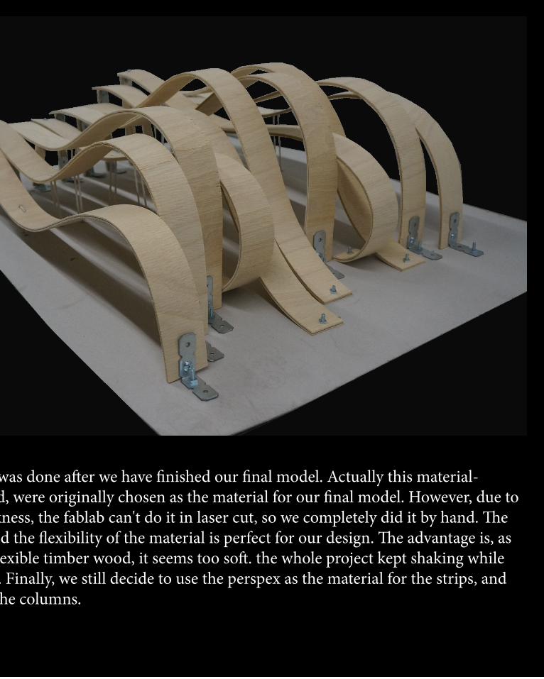
This protope was done after we have finished our final model. Actually this material-bending wood, were originally chosen as the material for our final model. However, due to its 8mm thickness, the fablab can't do it in laser cut, so we completely did it by hand. The thinkcness and the flexibility of the material is perfect for our design. The advantage is, as a laminated flexible timber wood, it seems too soft. the whole project kept shaking while we finished it. Finally, we still decide to use the perspex as the material for the strips, and plywood for the columns.
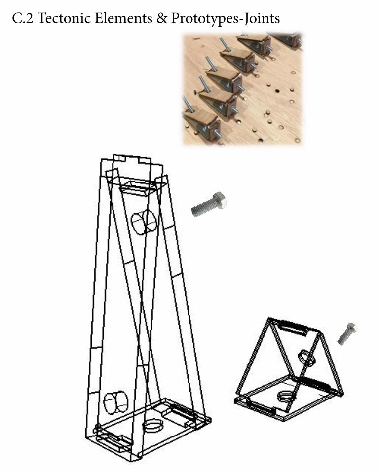
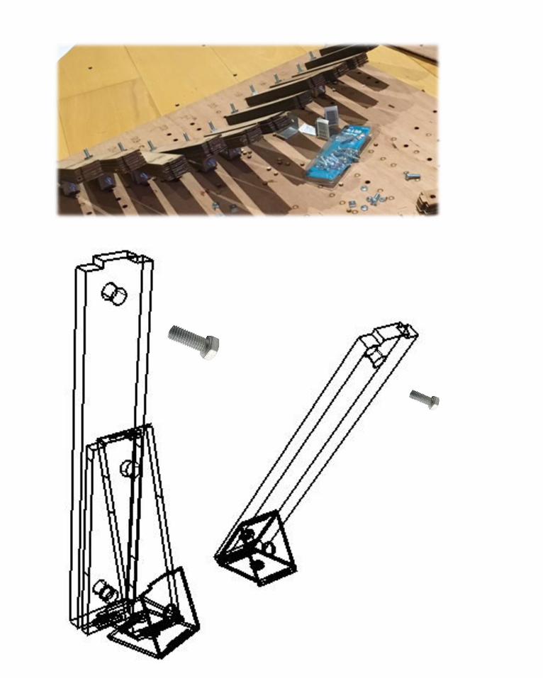
ConnectionsC.2 Tectonic Elements & Prototypes-Joints
Connections
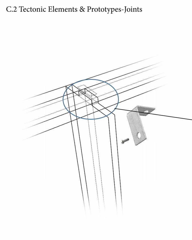
C.2 Tectonic Elements & Prototypes-Joints Connections
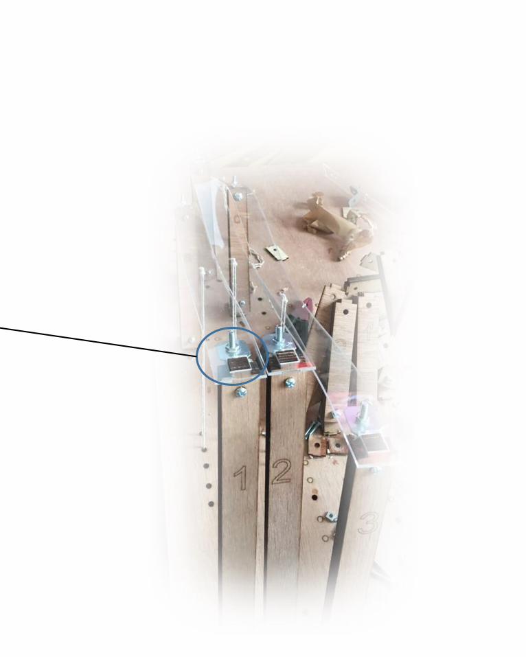
Connections

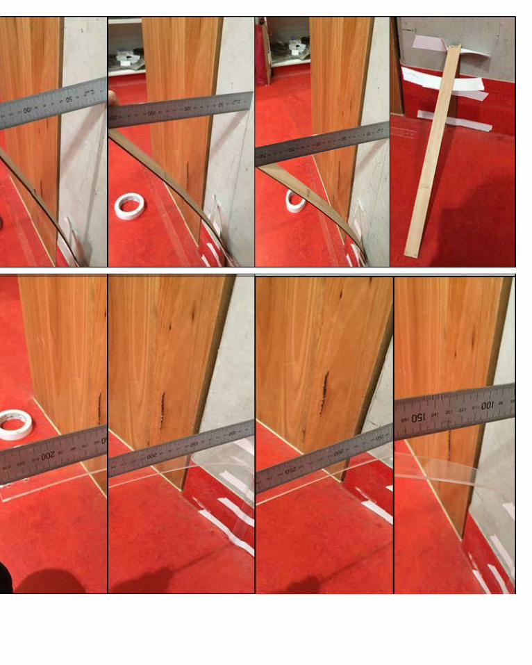
C.2 Tectonic Elements & Prototypes-Joints -Materiality
Before starting doing the final model, we made a material test for the material provided by the fablab. Plywood is hard and lack of flexibility, ductility. It had a crack while one side of the plywood stips wa about 25cm away from its staring point.
Perspex has better flexibility and ductility, because it was broken while it the one side is 42 cm from its starting point.

Process of the model making
C.2 Technical Elements & Prototypes

Process of the model making
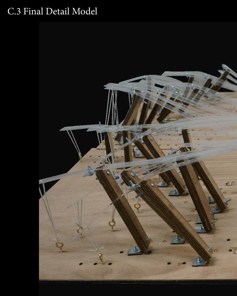
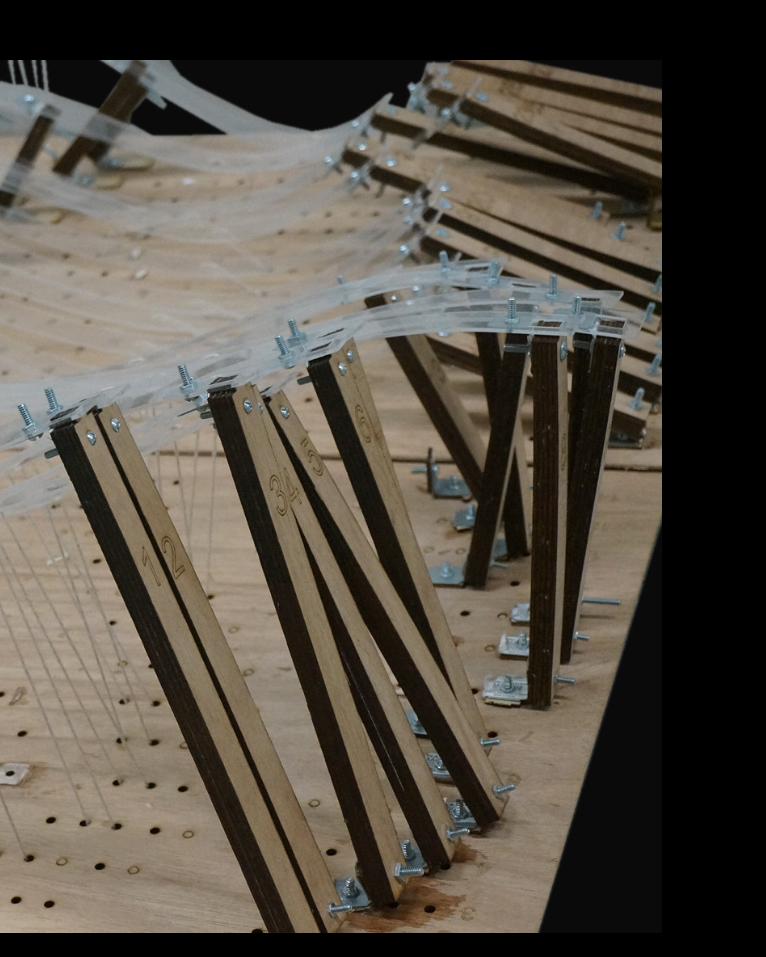
C.3 Final Detail Model
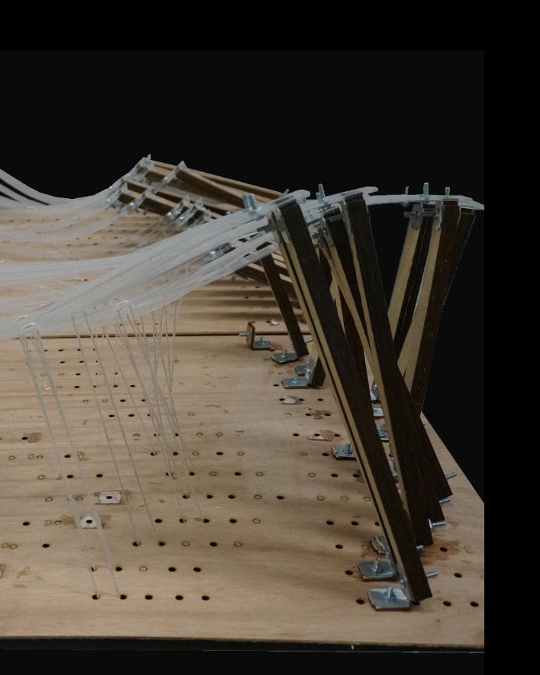

C.3 Final Detail Model


C.3 Final Detail Model


C.3 Final Detail Model

C.3 Final Detail Model-User Experience


C.3 Final Detail Model-User Experience


C.3 Final Detail Model-User Experience

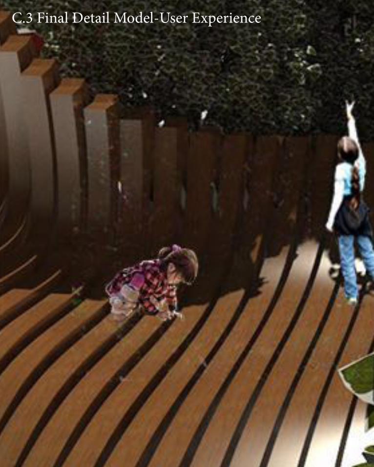
C.3 Final Detail Model-User Experience

C.4 Learning Objectives and OutcomesFirst of all, I want to say Air Studio is the most difficult, but the most useful subject since Year 1 in the university of Melbourne.
In this studio, parametric design and difital modelling are two main parts during the semester. To make a design throughout the parametric designing tools are totally different from the traditional design method that I have learnt in the past two years. At the beginning of the subject, I have no idea about how can I make a model by grasshopper. I can't understand how can i make out those shapes and geometries into digital model without drawing them out. It has been a completelu new experience to design an architecture with such tools.
Obviously, parametric design has many advantages, especially for engineers. For example, any elements you made in grasshopper can be used in many models. The part can be recalled in the future as parametric design can be archived. Instead of remodeling, recalling save more resources.
Through the studying of this semester in Air studio, my understanding of architecture have been strengthend. Parametric design method has became a trend. However, it has limtations as well. Hand-on approach on model-making allows architects and engineers to find the problem of their design in the early period, while parametric design can't. Undoubtedly, Parametric design tools provide more opportunities for architects in architecture, but we should never forget the purpose and the essence of architecture.
C.5 Reference
Emma Rudeck, The Pros and Cons of Parametric Modeling (2013) <http://www.concurrent-engineering.co.uk/Blog/bid/97311/The-Pros-and-Cons-of-Parametric-Modeling> [accessed 4 November 2015].