Embed Size (px)
Citation preview

1
© 2008 Fieldbus Foundation
2008 FFIMC - Automation 2008-Mumbai
Fieldbus Foundation – India Marketing Committee
Fieldbus Engineering MethodologyMurali Krishnan T
Emerson Process Management, Asia Pacific
Fieldbus FoundationParadigm Change in Instrumentation Technology
Date : 26th of September, 2008 (Friday) Time : from 09:00 am to 06:00 pm. Venue : Automation 2008 Conference Hall.
: Conference Hall, Bombay Exhibition Centre (NSE), Goregaon (East), Mumbai INDIA

2
© 2008 Fieldbus Foundation
2008 FFIMC - Automation 2008-Mumbai
Designing Fieldbus Segments
Segment Design ConsiderationsConstraint ChecksCommunications ProcessingComponents Selection

3
© 2008 Fieldbus Foundation
2008 FFIMC - Automation 2008-Mumbai
Segment Design ConsiderationsInstrument FunctionalityInstrument LocationProcess Control RequirementsAvailability Requirements

4
© 2008 Fieldbus Foundation
2008 FFIMC - Automation 2008-Mumbai
Instrument Functionality
Pick the right instrument for the applicationFind out which function blocks are available with an instrumentMost common function blocks are AI, AO, PID, DI, DO

5
© 2008 Fieldbus Foundation
2008 FFIMC - Automation 2008-Mumbai
Transmitter
PID with Auto TuningOutput Splitter (OS)Control Selector (SEL)ArithmeticIntegratorSignal Characterizer
6
© 2008 Fieldbus Foundation
2008 FFIMC - Automation 2008-Mumbai
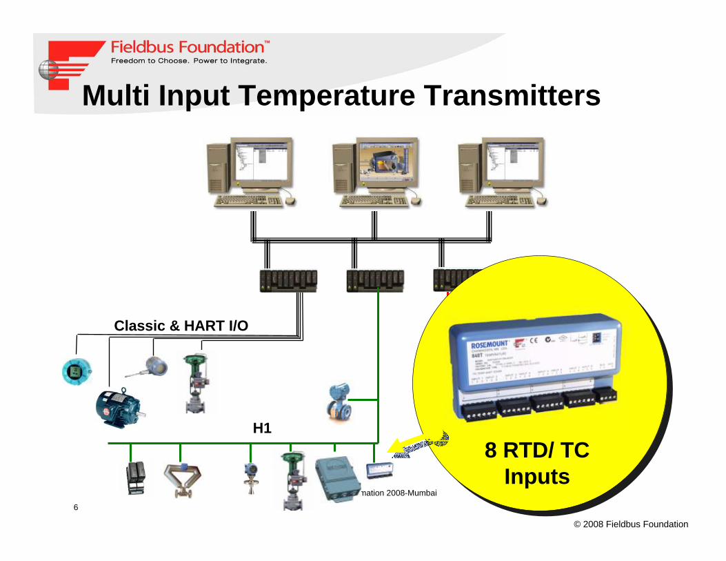
Multi Input Temperature Transmitters
Classic & HART I/O
H1AS-i
DeviceNet/Profibus
8 RTD/ TC Inputs

7
© 2008 Fieldbus Foundation
2008 FFIMC - Automation 2008-Mumbai
Discrete I/Os Transmitter
Classic & HART I/O
H1AS-i
DeviceNet/Profibus
8 DI / 8 DO& logic

8
© 2008 Fieldbus Foundation
2008 FFIMC - Automation 2008-Mumbai
Process Control Requirements
How are the measurements being used?Monitor only or used in PID control?Required update time?Input processing, such as P-T compensation?Output processing, such as split-range?

9
© 2008 Fieldbus Foundation
2008 FFIMC - Automation 2008-Mumbai
Process Control Requirements
The measurement device and control element of a PID loop must be on the same segment for Control-in-field (CIF)The PID Function Block can be located in the transmitter (CIF), valve (CIF), or… control can be in the controller (CIC)Where to locate the PID block(s) depends on the complexity of the control strategy

10
© 2008 Fieldbus Foundation
2008 FFIMC - Automation 2008-Mumbai
Availability Requirements
Redundancy requirementsEquipment segregationDistribution of critical loopsComponent redundancy- Fieldbus Power supplies/Power Conditioners- H1 card- LAS (Back up LAS in a field device)

11
© 2008 Fieldbus Foundation
2008 FFIMC - Automation 2008-Mumbai
Designing For Process Modularity
Hot Oil Return
D-38004
D-38003
D-36003
D-36004
Condensate Stripper
Raw Methanol Stripper
Fuel Gas Header
Weir
TT101A LT101
FT501
100%
100%
TT101B
PT401
LT101
Segment 2
PIDAI AO
Segment 1

12
© 2008 Fieldbus Foundation
2008 FFIMC - Automation 2008-Mumbai
Process Safety Levels (Client Driven)Level 1 ValvesFailure of this valve will result in a total system trip, causing a shutdown of the entire unit, or other unavoidable losses in excess of $100M. Level 1 valves and their associated measurement shall reside on H1 segments with no other devices. The ISD shall show the criticality rating and shallprominently display that no additional devices shall be loaded on this segment. Level 2 ValvesFailure of a level 2 valve will result in an emergency situation, where prompt operator action would be required to "save" the unit from immanent total shutdown. The material and energy capacity ofassociated vessels, geographic location, and elevation/accessibility of such valves should be considered. Failure of a level 2 valve will result in a total system trip, causing a shutdown of the entire unit, or other unavoidable losses in excess of $100M. However, the level 2 valve's process dynamics allow time for quick recovery from the failure, either by quickly fixing a fault or by taking manual control. Level 2 valves and their associated measurement shall reside on H1 segments with no otherlevel 1 or 2 valves. The ISD shall show the criticality rating.Level 3 ValvesFailure of this valve will not result in any short-term risk of total unit shutdown. Level 3 valves can go to their fail position without requiring any immediate operator action. Level 3 valves can reside on cards or segments with other level 3 valves, or on a segment with a level 2 valve. Consideration should be given to the impact of common mode failures among level 3 and level 2 & 3 valves on the same segment.
EXAMPLE ONLY – VARIES WITH CUSTOMER

13
© 2008 Fieldbus Foundation
2008 FFIMC - Automation 2008-Mumbai
Assigning Fieldbus Devices to a Segment
Maximum 16 devices per segmentRecommended loading- Total of 12 devices per segment- Total of 4 control loops per segment
Devices should be placed on segments based on location, control function, and reliability requirements

14
© 2008 Fieldbus Foundation
2008 FFIMC - Automation 2008-Mumbai
Constraint Checks
Distance LimitsSpur LengthPower ConsumptionVoltage DropCommunications Processing

15
© 2008 Fieldbus Foundation
2008 FFIMC - Automation 2008-Mumbai
Spur Length
Terminator Terminator
Trunk
Spur
T T
16
© 2008 Fieldbus Foundation
2008 FFIMC - Automation 2008-Mumbai
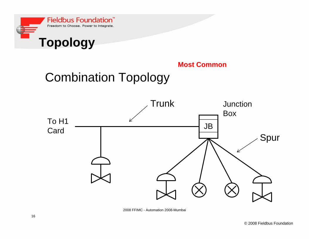
Topology
Trunk
To H1Card
Combination Topology
JBSpur
JunctionBox
Most Common

17
© 2008 Fieldbus Foundation
2008 FFIMC - Automation 2008-Mumbai
Fieldbus Network Components (non-IS)
PCPS
T1 +S1 +S2 + S21 +S22 +S23 ….+ Sn<1900 m
S1 S3 Sn
S23
S22
S2
S21
Branch
Tree
Segment / TrunkSegment / Trunk– The section of the fieldbus that is terminated.– Max. 1900 m per segment– Max. 32 devices per segment
T1 TT
SpurSpur– Branch line from Segment– Distribute devices along the Segment– Final Circuit– Max. length 120 m

18
© 2008 Fieldbus Foundation
2008 FFIMC - Automation 2008-Mumbai
Voltage Drop
26 ma
11 ma
15 ma
17 ma
Total = 69 ma
Fieldbus Power Supply19 V
3000 feet
#18 AWG, 6.4 Ω/1000ft
Voltage = 19 - [ (3000 x 6.4/1000 x 69/1000) x 2 ]Voltage = 19 - 2.65Voltage = 16.35

19
© 2008 Fieldbus Foundation
2008 FFIMC - Automation 2008-Mumbai
Segment Power Considerations
Junction Box
FieldbusPowerSupply
• Non-IS Application (Safe)
• Intrinsic Safety Models• Entity (IS)• FISCO (Zone 1)• FNICO (Non incendive)
• Field Barriers
? ?

2008 FFIMC - Automation 2008-Mumbai
Single
Power Conditioner(Examples)
Redundant,Multi-segment
FISCO, FNICO
Redundant,Multi-segment

2008 FFIMC - Automation 2008-Mumbai
Wiring Blocks(Examples)
Zone 2Ex nL
Zone 1Ex me
Zone 1/0Ex ia
Fieldbus BarriersEx me [ia]

22
© 2008 Fieldbus Foundation
2008 FFIMC - Automation 2008-Mumbai
Fieldbus Design Tools (Examples)

23
© 2008 Fieldbus Foundation
2008 FFIMC - Automation 2008-Mumbai
Fieldbus Segment Design Tool Report

24
© 2008 Fieldbus Foundation
2008 FFIMC - Automation 2008-Mumbai
Link Active Scheduler runs segment
Link Active Scheduler (LAS) is the data “Traffic Cop” of the segment- Controls all access to the segment- Keeps track of who is on the segment- Runs Macro Cycle- Time Clock for segment
LAS can be in any device on segment that has the capability- All host have LAS- Many devices have LAS

25
© 2008 Fieldbus Foundation
2008 FFIMC - Automation 2008-Mumbai
Communications Processing
The LAS allocates both scheduled (for closed loop control) and unscheduled (Set point, monitoring loops, alarms) time on the busMacrocycle time depends on block execution speed, number of blocks, communications between blocks, etc.

26
© 2008 Fieldbus Foundation
Scheduling
Time
Scheduled Cyclic Communication
UnscheduledCommunication
AI
PID
AO
Scheduled FunctionBlock Execution
FUNCTION BLOCK SCHEDULING
LAS Schedule Macrocycle
LAS Schedule Macrocycle

27
© 2008 Fieldbus Foundation
2008 FFIMC - Automation 2008-Mumbai
PIDIN OUT
BKCAL_IN FIELDVUE
AO
BKCAL_OUT
CAS_IN
AIOUT
Valve
Transmitter
Function Blocks in FOUNDATION™ fieldbus Solutions
28
© 2008 Fieldbus Foundation
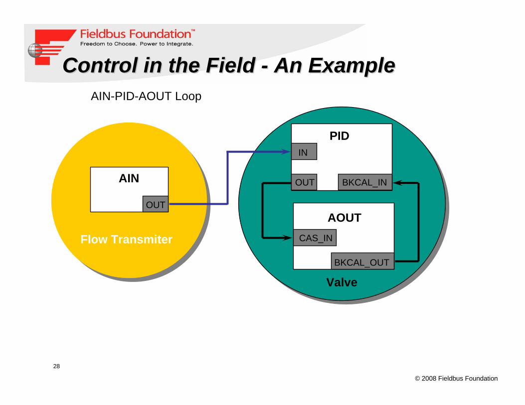
ControlControl in the Field in the Field -- An ExampleAn Example
AIN
Flow Transmiter
OUT
Valve
AOUT
PID
BKCAL_OUT
CAS_IN
BKCAL_INOUT
IN
AIN-PID-AOUT Loop

29
© 2008 Fieldbus Foundation
2008 FFIMC - Automation 2008-Mumbai
Communications Processing
AI PID AO
20ms
30ms
30ms
25ms
This sample loop on a segment results in a minimum 105 ms macrocycle time.
AI PID AO
20ms
30ms
30ms
25ms
> 105 ms

30
© 2008 Fieldbus Foundation
2008 FFIMC - Automation 2008-Mumbai
Communications Processing
Adding a second loop on the segment results in a longer macro-cycle time, but not twice as long (30ms compelled data time).
AI PID AO
20ms
30ms
30ms
25ms
AI PID AO
AI PID AO
20ms
30ms
30ms
25ms
AI PID AO
> 135 ms

31
© 2008 Fieldbus Foundation
Advantages of Control in the FieldFOUNDATIONTM fieldbus allows for control in the field!
Deterministic Control Single loop integrity availableFaster Speed of responseFree up controller to handle advanced applications (embedded APC)Devices with more function blocks offer more flexibility for Control in the Field

32
© 2008 Fieldbus Foundation
2008 FFIMC - Automation 2008-Mumbai
Instrument data Sheets for Ff devicesInstrument data Sheets for Ff devicesWorking voltage (9-32 volts)Maximum current draw from busFunction block requirementsBlock execution speedsStandard/Advanced Diagnostics requirementsInteroperability tested (ITK4.0 – FF base standard)Polarity sensitivityCapacity for instantiable function blocksLAS capabilityDevice revisionChannel number and descriptionAny local indicator required

33
© 2008 Fieldbus Foundation
2008 FFIMC - Automation 2008-Mumbai
Fieldbus View Macrocycle
Graphs the macrocycle for a given segment
Quickly evaluate Fieldbus segment communications
Quickly evaluate Fieldbus segment communications
34
© 2008 Fieldbus Foundation
2008 FFIMC - Automation 2008-Mumbai
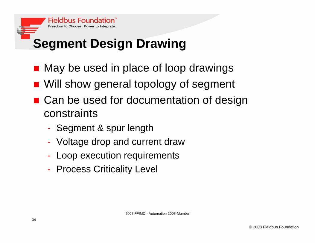
Segment Design Drawing
May be used in place of loop drawingsWill show general topology of segmentCan be used for documentation of design constraints- Segment & spur length- Voltage drop and current draw- Loop execution requirements- Process Criticality Level

35
© 2008 Fieldbus Foundation
2008 FFIMC - Automation 2008-Mumbai
Sample Segment Drawing
Typical Instrument Segment DiagramMTL/REL Red. Power Cond.
March 23, 2004
None
Sudhir Jain
DATE:
SCALE:
DRAWING NO:
DESIGN: DRAWN:
CHECKED:
APPROVAL:
JOB: REV:
CAD FILE:
CUST.APPR.
PROJ.ENG.CHK:BY:REVISIONS
ISSUED FOR CUSTOMER APPROVAL
DATE:REV:
A
Emerson Consider It Solved
ISSUED FOR CONSTRUCTION0
0
Located @ xxxx
H1 Interf aceFieldbus ModuleController: 01Card: 03Port: 01
DeltaV Cabinet: DV-01
BK WH
H1 TerminalBlock
To Shield Bus Baron DeltaV Carrier
Field
BKWH
FJB-101
(Note: Ty pical wire taggingf or all f ield dev ices.)
Junction Box
Reference DrawingsCabinet Wiring Details
P&ID
84 -
5 +
76 -
1 2
Cable #Multipair cable or Single pair
XXXX Meters
BK
WH
BKWH
BKWH
BK
WH
BKWH
BKWH
BK
WH
BK
WH
Fieldbus
XX M
Fieldbus
XX M
Fieldbus
XX M
Fieldbus
XX M
Fieldbus
XX MBK
WH
BKWH
Single Pair141-PV-101
BKWH
Note:
This is a one piece block (Megablock) that has internaljumpering, (i.e. no hard-wired jumpers required). Hard-wired jumpers are required when y ou tie two blockstogether.
This block can be ordered with internal spurguards whichlimits the spur current to 60 mA during a short circuitcondition.
The connectors are pluggable theref ore commissioningand maintenance are simplif ied.
3 +
FPS/01-0301
PortCardController
BK
WH
BK
WH
T +-S
BK
WH
BK
WH
BK
WH
BK
WH
BK
WH
Relcom/MTL RedundantPower Conditioner
Emerson Process Management
Fieldbus
XX M
Fieldbus
XX M
Fieldbus
XX M
Fieldbus
XX M
Fieldbus
XX M
Fieldbus
XX M
Fieldbus
XX M
Cut & Tape(Typ. for all)
BK
WH
BK
WH
BK
WH
BK
WH
BK
WH
BK
WH
BK
WH

36
© 2008 Fieldbus Foundation
2008 FFIMC - Automation 2008-Mumbai
Fieldbus Design Tools and DocumentsThe following is a summary ofcommon tools/documents used inFieldbus Design and Implementation:
Fieldbus Design Methodology (FDS) : A document that spells out factors to take into consideration during the design process.Segment Design Tool : In the form of drag and drop to check segment designVendor-specifc documents for Procedures, Application Notes and Design Review Foundation Fieldbus Installation Guide.Fieldbus Pre-commissioning Procedure.Fieldbus Troubleshooting Guide
Fieldbus Troubleshooting GuideFieldbus Troubleshooting GuideFieldbus Troubleshooting Guide
DeltaV Foundation Fieldbus Installation Guide.DeltaV Foundation Fieldbus Installation Guide.

37
© 2008 Fieldbus Foundation
2008 FFIMC - Automation 2008-Mumbai
Designing Fieldbus Segments - Summary
1. Select the proper instrumentation2. Group according to location & control
function3. Lay out fieldbus segment4. Check segment length & spur length5. Check current draw & voltage drop6. Check communications loading7. Choose wiring methods8. Choose components


![Profibus PA Fieldbus Display [ Revision 2 ] and Fieldbus ... Instruments... · Profibus PA Fieldbus Display [ Revision 2 ] and Fieldbus Indicator Fieldbus Interface Guide. ... Siemens](https://img.dokumen.tips/doc/110x75/5b2fe38e7f8b9ae16e8da83d/profibus-pa-fieldbus-display-revision-2-and-fieldbus-instruments.jpg)