Embed Size (px)
Citation preview

Progress In Electromagnetics Research B, Vol. 71, 153–166, 2016
Field-Excited Flux Switching Motor Design, Optimization and
Analysis for Future Hybrid Electric VehicleUsing Finite Element Analysis
Erwan Sulaiman1, *, Faisal Khan1, and Takashi Kosaka2
Abstract—Design, optimization, and performance analysis of a three-phase field-excited flux switching(FEFS) motor to be employed for the future hybrid electric vehicle (HEV) drive applications isinvestigated in this paper. The stator of designed motor made of electromagnetic steels is composedof unique field mmf source and armature coils while a rotor is made of iron stack. This design hasbeen evaluated in order to achieve power and torque density higher than 3.50 kW/kg and 210 Nm,respectively, so as to compete with the interior permanent magnet synchronous (IPMS) motor commonlyinstalled in HEV. Given its robust rotor structure, the maximum achievable motor speed went up to20,000 rpm. To perfect the motor design, a deterministic optimization approach was applied to meet thestringent performance requirements. In addition, experimental analyses were carried out to confirm theeffectiveness of the proposed motor. Positively, the proposed FEFS motor has proved to be a suitablecandidate of non-permanent magnet motor for efficient and safe HEV drive.
1. INTRODUCTION
Driven by concern about the environment, automakers, government, and automobile users retain a keeninterest in electric vehicle (EV) and hybrid electric vehicle (HEV), which makes the research in thisarea intriguing. As electric motors are the core of electric propulsion system, initiatives to developadvanced, state-of-the-art electric motors have been undertaken [1, 2]. So far to reduce environmentpollution among other benefits, HEV is known to be the most promising green vehicle using combinationof internal combustion engine (ICE) and one or more electric motors. DC motor, induction motor(IM), switch reluctance motor (SRM), and permanent magnet synchronous (PMS) motor are potentialcandidates of electric motors for HEV drives, as shown in Fig. 1. Among them, DC motor has the abilityto operate only at DC supply and therefore widely used in HEV. Besides, the DC motor can be simplycontrolled based on the orthogonal disposition of field and armature mmf. However, the maintenanceproblem due to the use of commutator and brush, DC drive encounters renders it unsuitable for HEVand less reliable for maintenance-free drive [3–6].
Researchers have investigated the possibility of IM — a non permanent magnet (PM) motor— among brushless machine for electric propulsion system. Cage IM is acknowledged as the mostpossible candidate due to reliability, cost-effectiveness, ruggedness, and capability of operating in hostileenvironment. Nonetheless, its relatively low efficiency in the low speed, light load region of HEV mayaffect fuel consumption and degrade system efficiency. Additionally, IM drive has such problems of lowtorque density and low power factor which contradict the requirement for high electric loading. Thesestringent conditions particularly turn into major disadvantages of IM, thus eliminating it from being asuitable candidate for electric propulsion system of HEV [7–9].
Received 25 September 2016, Accepted 27 October 2016, Scheduled 6 December 2016* Corresponding author: Erwan Bin Sulaiman ([email protected]).1 Universiti Tun Hussein Onn Malaysia, Parit Raja, Batu Pahat, Johor 86400, Malaysia. 2 Nagoya Institute of Technology (NITech),Nagoya, Japan.

154 Sulaiman, Khan, and Kosaka
Armature
coil
PM Stator
Rotor Rotor
Armature coil
PM
Rotor
Armature coil
Stator
(a) (b) (c) (d)
Figure 1. Four major candidates for HEV drive, (a) DC motor, (b) IM, (c) SRM, (d) IPMS motor.
Meanwhile, SRM, a non-PM motor, is familiarly recognized to have great potential for HEVapplications. Its merits include low manufacturing cost, fault tolerance, simple and rugged construction,simple control, and much better torque-speed characteristics than IM. Overall, SRM has the abilityto operate at very wide constant power range. However, it has disadvantage and unsuitable for HEVpropulsion system due to large torque ripples, vibration problem, acoustic noise which imposes excessivebus current ripple, special converter topology, and electromagnetic interference that causes additionalnoise [10–14].
In contrast, IPMS motor is brushless machine and has various attractive characteristics comparedwith other machines installed in HEV. Hitherto, IPMS motor retains its competitive advantage overother electric motors concerning HEV’s electric propulsion system. In fact, the renowned automakerssuch as BMW, GM, Renault-Nissan, Toyota, Honda have long adopted IPMS motor in considerationof its advantages of small size, light weight, high power density, high reliability, high torque, and highefficiency. In 2009, IPMS motor was successfully installed on Toyota Prius [15]. This can be verifiedby historical development in the power density of main traction motor installed on Toyota HEVs. Overthe years, power density of IPMS motor has been improved by at least five times, with enhancementmore conspicuous than its first appearance in Toyota Prius in 1997 [16]. Although it is very hard toameliorate the torque density of a motor, integrating a reduction gear has enabled elevation of theaxle torque necessary for propelling large vehicle. Along this line, one effective strategy to increasethe power density of a motor would be to combine high-speed motor with reduction gear. For dual-excitation switched-flux (DESF) motor, the PM volume is reduced by half of that employed in IPMSmotor, yet maintaining the power density at maximum value [17]. Nevertheless, compared with dual-excitation switched-flux (DESF) motor, IPMS motor is heavier because it consists of more componentsand materials. In this regard, dual-excitation FSM motor prides itself on lower cost and smaller size.
However, with the growing demand for EVs and HEVs, the annual consumption of rare-earth PMby IPMS motor has increased accordingly. This causes the prices of Neodymium (Nd) and Dysprosium(Dy) — an essential additive to provide the rare-earth PM with high coercivity — to rise markedly.Together, they raise serious concerns about soaring cost, security matters, and supply shortages. Hence,continuous research effort to develop electric motors with robust rotor structure and high power densitywithout relying on rare-earth magnet is of the utmost importance [18].
To overcome the above mentioned obstacles, PM of DESF motor can be eliminated by FE coilexcitation only on the stator, to form FEFS motor as shown in Fig. 2. Briefly, the principle of operationof FEFS motor is based on switching the flux polarity linking with the armature coil windings byaltering the rotor position. Single-phase FEFS motor with 4 stator slots and 2 rotor poles (4S-2P) composed of a FE coil, fully-pitched windings on the stator, and a toothed rotor structure isdemonstrated in Fig. 2(a) [19]. As clearly illustrated, the two armature coils and a FE coil areoverlapping each other in the stator. The practicability of this motor design has been investigatedfor various applications requiring high power density with a good level of durability [20, 21]. In thisdesign, desired flux orientation for rotation is provided by the single-phase AC armature windings andDC FE coil arrangements. The required torque is produced by variable mutual inductance of windingsmaking it different from SRM. In fact, the single-phase FEFS motor together with a power electroniccontroller has very low cost and is easy to manufacture yet with impressively high throughput [19].Furthermore, being an electronically controlled brushless motor, it has longer lifetime, is flexible, andallows precise control of speed, torque, and position at no additional cost compared with other machines.

Progress In Electromagnetics Research B, Vol. 71, 2016 155
FEC
Armature coil
FEC
FEC
Armature coil
Armature coil FEC
FE FE
FE
FE
FE FE
FE
FE
A1 A1
A1
A1
A1 A1
A1
A1
Stator Rotor
FE FE
FE
FE
FE
FE
A1 A1
A1
A1 A1
A1
A1 A1
A1 A1
FE FE
FE
FE
FE FE
FE
FE
(a) (b) (c)
(d) (e)
Figure 2. (a) Single-phase 4S-2P FEFS motor, (b) single-phase 8S-4P FEFS motor, (c) single-phaseFEFS motor with salient rotor, (d) single-phase 12S-6P FEFS motor, (e) single-phase 8S-8P FEFSmotor.
Another example of single-phase 8S-4P FEFS motor is shown in Fig. 2(b) [22]. When field currentis applied to the field winding in four of the slots, four-pole magnetic field is formed. The armaturewinding in the remaining four slots is pitched over two stator teeth. A set of four stator poles carryflux while the rotor position is determined by current’s direction in the armature winding. As FEcoil is excited by current of single polarity, it will have direct connection either in parallel or in serieswith DC supply of power converter which feeds bipolar current into the armature winding. The theoryunderlying this design is explained in [23], where single-phase 8S-4P FEFS motor is compared with IMand demonstrates higher output power density as well as better efficiency. Nonetheless, the single-phaseFEFS motor has some demerits fixed direction of rotation, large torque ripple, low starting torque, andoverlapping windings between FE coil and armature coil. Two single phase FEFS motor topologieswith DC field and armature windings having the same coil-pitch of two slot-pitches and different coil-pitches of one and three slot-pitches, respectively, have been discussed [24]. It is shown that the ironloss of FEFS motor has been reduced, thus increasing the efficiency. Nonetheless, these topologies haveproblem of less efficiency due to overlap windings as illustrated in Fig. 2(c) than single-phase FEFSmotor with non-overlap windings. Single-phase 12S-6P FEFS motor with segmental rotor has beendesigned for high density air-conditioner and discussed in [25]. Due to non-overlapping windings, theproposed motor has less copper losses as shown in Fig. 2(d) than single-phase FEFS motor with salientrotor. Although single-phase 12S-6P FEFS motor has the capability to produce high output power, itis unsuitable for high-speed applications due to non-robust segmental rotor. Performance analysis ofsingle-phase 8S-8P FEFS motor, depicted in Fig. 2(e), is discussed in [26]. The proposed motor hashigh cogging torque, overlap armature and field windings which make it not suitable to be applied toany electrical equipment.
To meet the rigid performance requirements, a three-phase 24S-10P FEFS motor has been builtupon the existing 24S-10P PMFS motor, by replacing PM with FE coil at the stator and arranging FEcoil windings at the upper half layer of armature coil slots as illustrated in Fig. 3(a) [27]. It is noticeablethat FE Coil-1 and FE Coil-2 are arrayed along with alternate DC current source polarities to producetwo flux polarities, similar to PM polarity of 12S-10P PMFS motor. The main disadvantage of thisconfiguration is that the isolated and unused stator teeth, as highlighted by red circles, decrease theoverall motor performance.
To improve the drawbacks of FEFS motor, 12S-8P segmental rotor FEFS motor has been proposed,as shown in Fig. 3(b) and experimentally analyzed [28]. Non-overlapping windings arrangement isemployed which gives shorter end windings than tooth rotor structure with distributed or overlapping

156 Sulaiman, Khan, and Kosaka
Armature coil
A1
B1
C1
B2
C2
A3
B3
C3 A4
B4
C4
A2
FEC
Armature coil
FEC
Armature coil
A1
B1
C1
A2 B2 C2
A3
B3
C3
A4 B4 C4
(a) (b) (c)
(d) (e)
Figure 3. (a) Three-phase 24S-10P FEFS motor, (b) 12S-8P segmental rotor FEFS motor, (c) 24S-10PFEFS motor with single FE coil, (d) 12S-14P FEFS motor with toroidal DC winding, (e) outer rotorFEFS motor.
windings. This design has noteworthy gains over other designs as it consumes less conductor materials,accordingly enhances the overall efficiency due to reduction of copper loss. However, the motor is notsuitable for high-speed applications due to less robust structure. FEFS motor with single polarity FE coilwas discussed in [29], as illustrated in Fig. 3(c). FEFS motor with single polarity FE coil has advantagesof low copper loss and less leakage flux than dual FE coil windings. The field-weakening capabilityof FEFS motor is improved using toroidal dc field winding, as shown in Fig. 3(d) [30]. Although theproposed machine has generated high torque, the copper losses will be high due to overlapping windings.
In recent years, in-wheel motor for EV drive train system raises the challenge for motor design andis increasingly considered due to its numerous advantages of high efficiency, no mechanical axis andindependent wheel controllability. Additionally, more cabin space is available due to the eliminationof differential and mechanical axis conventionally used in most of existing HEV. In view of the factthat the outer-rotor configuration is more suitable for direct drive, the PMFS motor with outer-rotorhas been explored only for light EV applications [31]. It provides essentially high torque at low speedand sinusoidal back-electromotive force (emf). However, it is difficult to control flux of PMFS motorwhich requires field weakening flux at high-speed conditions. 12S-10P outer rotor FEFS motor has beeninvestigated conventionally and discussed in [32], as illustrated in Fig. 3(e). Salient rotor structurewith high mechanical strength and less cost due to no PM are clear advantages of this machinewhile overlapping windings arrangements create problem of high copper losses. It can be concludedfrom the discussions that all motors have various problems that must be resolved for their practicalimplementation.
In this paper, the design, optimization, and performance analysis of 12slot-10pole FEFS motor —an alternative non-PM motor for HEV drive — is elucidated. The motor stator consists of laminatediron core, armature coils, and DC FE coils as the sole field mmf source. As with SRM, the rotor ofthis motor is made only of laminated iron core. Since the motor is driven by three-phase sinusoidalcurrent/voltage, the acoustic noise is not a concern [33]. Retrospectively, design feasibility studies inaccordance to two-dimensional finite element analysis (2D-FEA) are conducted to attain the desiredtargets of power density higher than 3.5 kW/kg and maximum torque greater than 210 Nm. Usingthe prototype of final FEFS motor design, a few experimental tests are performed. Encouragingly,

Progress In Electromagnetics Research B, Vol. 71, 2016 157
experimental outcomes confirmed that the proposed motor is a suitable candidate of non-PM tractionmotor for HEV drive.
2. DESIGN SPECIFICATIONS AND RESTRICTIONS FOR TARGETED HEVAPPLICATIONS
The design specifications and restrictions of FEFS motor for HEV applications are shown in Table 1,taking the estimated and available values of IPMS motor in [11] as reference. Assuming that there isonly one water cooling system, the current densities of FE coils and armature windings are respectivelyset to the highest values of 21 A/mm2 and 21 Arms/mm2. The stack length of stator core and the outerdiameter of stator are identical to those of IPMS motor. Given the laminated iron core, the rotorstructure of the proposed motor is expected to be mechanically strong for high-speed rotation. Indeed,the motor is capable to operate at maximum speed up to 20,000 r/min. As for the required maximumtorque of 210 Nm, it is decided by realization of maximum axle torque — comparable to that of IPMSmotor — via reduction gear at a ratio of 4 : 1. Similar to that of IPMS motor, the maximum outputpower is set to be greater than 123 kW while the calculated weight of motor is less than 35 kg, yielding thehighest power density of 3.5 kW/kg. In this investigation, a commercial FEA solver, JMAG released byJSOL Corporation, is used for 2D-FEA. The partial differential equation based on Maxwell’s equationsexplaining the physical behaviour of the magnetic field distribution in the x-y plane cross section of themachine solution domain discussed in [34, 35] can be stated as,
∂
∂x
(ν
∂Bz
∂x
)+
∂
∂y
(ν
∂Bz
∂y
)= −Jz (1)
where Jz , Bz are the axial(z) components of the total current density and magnetic vector potential, andν is the magnetic reluctivity of the medium. Meanwhile, the current density, Jz , in Eq. (1) is uniformlydistributed in the field and armature windings. The whole procedure to model the electric machinesusing finite element method is discussed in [36]. The finite element computations are performed toanalyse the performance of proposed motor and further validated experimentally.
Table 1. Design specifications and restrictions of FEFS motor.
Items Unit IPMS motor FEFS motorMaximum DC-bus voltage inverter V 650 650
Maximum inverter current A Conf. < 260Maximum Ja A/mm2 Conf. < 21Maximum Je A/mm2 NA < 21
Ratio of reduction gear 1 : 2.478 1 : 4Radius of shaft mm 30 30
Stack length of motor mm 70 70Total PM weight of FEFS motor kg 1.1* < 1.0
Length of air gap mm 0.8 0.8Maximum torque of motor N · m 333 > 210Outer diameter of stator mm 264 264Maximum speed of motor r/min 12,400 20,000
Maximum power of FEFS motor kW 123 > 123Power density kW/kg 3.5* > 3.5

158 Sulaiman, Khan, and Kosaka
3. CONFIGURATION OF INITIAL 12SLOT-10POLE FEFS MOTOR
Figure 4 displays the cross-sectional view of initial FEFS motor design, with black and dotted linesrepresenting FE coil and armature coil, respectively. Visibly, the motor has 10 rotor poles and 12armature coil slots in the stator. Each of the twelve FE coil slots is arranged unvaryingly in the middleof every corresponding armature coil slot. Technically, DC is applied to FE coils to create 6 southpoles interspersed with 6 north poles. At a standstill, the generated magnetic fields circulate aroundrotor poles to form a complete cycle. As the rotor rotates, the polarity of magnetic fields is switchedalternately by chasing the rotor pole position. The three-phase armature coils are quartered at regularintervals in the stator body, as represented by red-yellow-blue color in the figure. When the rotorbegins rotating, the fluxes produced by mmf of FE coils start linking with armature coils. When therotor rotates through 1/10 of a revolution, the flux linkage with armature coil makes just one electricalcycle, and thus, the induced voltage frequency in armature coil turns into ten times of the mechanicalrotational frequency. As with SRM, the designed motor is suitable as well as robust for high-speedoperation as long as its rotor consists only of single-piece iron core.
In this research study, the selection of 12slot-10pole motor is justified by the following reasons:First, it is considered the best minimum slot-pole combination to avoid odd rotor pole number, whichleads to unbalanced pulling force [37]. Second, get around much torque ripples, as in the case of 8-pole or4-pole machine [38]. Third, strike a good balance between stator and rotor’s tooth widths for reducingunavoidable torque pulsation. On the whole, the choice of preliminary FEFS motor design is based onthe general suppositions as follows [17, 27]:(i) The split ratio (rotor outer radius divided by stator outer radius) for an electric motor is 0.6 to 0.7.(ii) The rotor outer radius for FEFS motor is set to be 92.4 mm, that is 70% of stator outer radius of
132 mm.(iii) The opening angles of armature coil slots, FE coil slot, and stator teeth are set identically as 7.5◦.
All FE coil slot and armature coil slots are rectangular in shape having the same slot depth. Theseconditions avoid magnetic saturation in the teeth, ensure sufficient mmf contributed jointly byarmature coils and FE coil while facilitating design optimization.
(iv) The opening angle for each rotor pole is calculated by dividing the sum of opening angles of statorteeth by the number of rotor poles. In the case of 12slot-10pole motor, the opening angle forevery rotor pole is set to be 18◦, which is one-tenth of the sum of opening angles of stator teeth of180◦. It is important to note that narrower opening angle of a rotor pole will give rise to magneticsaturation in rotor teeth. In contrast, too wide an opening angle will make fluxes flow more easilyfrom the stator, during which some of the flux movements may create negative torque.
(v) The stator back yoke thickness is set as 6 mm — half of inner tooth width of stator — to assumethat the flux flowing in the tooth is divided into two adjoining yokes.
Figure 4. Top view of initial 12slot-10pole FEFS Motor design.
Figure 5. Parameters of 12slot-10pole FEFS Motordesign.

Progress In Electromagnetics Research B, Vol. 71, 2016 159
(vi) The rotor pole depth is set to be 30.8 mm, that is one-third of rotor outer radius, ensuring sufficientthickness of rotor back yoke whereas avoiding flux leakage due to fringing.
4. DESIGN PARAMETERS AND PROCEDURE
Drived performance parameters of initial FEFS motor design are computed and evaluated at thebeginning of the design process. The power and maximum torque are 74.1 kW and 154.5 Nm,respectively, which are far from the required values. In an effort to ensure that performance targetsare met, free design parameters are defined as D1 to D7 (see Fig. 5). The deterministic optimizationmethod proposed by [17] is applied to update the design parameters repetitively until all performancetargets are achieved. To start with, the rotor design parameters — D1, D2, and D3 — are updatedwhile the stator design parameters — D4, D5, D6, and D7 — remain unaltered.
In theory, torque is directly proportional to the square of radius of rotor D1 when specific magneticand electric loadings are kept constant. In order to achieve the maximum torque, the radius of rotor D1
becomes the most significant parameter to be manipulated. Meanwhile, the other design parameters— D2 to D7 — are unchanged, and they vary according to displacement of D1. Once the optimumD1 value that generates the highest torque is found, it is kept constant while rotor pole width (D2)and rotor depth (D3) are updated. Subsequently, the optimum values of D1, D2, and D3 that producethe highest torque are kept unchanged, whereas the stator parameters, FE coil D4 and FE coil D5,are altered while keeping fixed values of D6 and D7 as set initially. The finest combination of D4
and D5 that brings about target values — in terms of power capability and maximum output torque— is determined under specific mmf of armature windings corresponding to the assigned D6 and D7.Lastly, the design parameters D6 and D7 are altered though the foregoing parameters are kept constant.These steps result in a set of seven design parameters D1 to D7 which enable FEFS motor to achievewell-balanced performance under the limitations of the given maximum voltage, current, and currentdensities. For the sake of perfection, the aforementioned design procedure is repeated by varying D1 toD7 until the targeted power and torque are attained. Throughout the optimization process of design,the air gap length is set as 0.8 mm. To ensure smooth flux flow around the slots and considerationof the manufacturing constraint, the circled corners in Fig. 5 are reshaped with circular line in finaldesign. Fig. 6 shows the cross-sectional view of final FEFS motor, while Fig. 7 shows the comparison offlux vector diagram under maximum current densities of armature (Jamax) and FE coil (Jemax) betweeninitial and final FEFS motor designs. Evidently, high flux density saturation is observed at statorback yoke as compared with the final design that has been mitigated. In reality, the stator back yokethickness in the final motor design has been expanded in order that much flux can flow easily withoutany hindrance to boost the maximum torque value. Table 2 summarizes the comparison of designparameters between initial and final designs.
Figure 6. Cross-sectional view offinal 12S-10P design.
(a) (b)
Flux saturation Less flux saturation
Figure 7. Flux vector diagram comparison between (a) initialand (b) final FEFS motor designs.

160 Sulaiman, Khan, and Kosaka
Table 2. Parameters of initial and final 12S-10P FEFS motor designs.
Details Units Initial FinalD1 Radius of rotor mm 92.4 97.2D2 Rotor pole width mm 14.45 10.0D3 Rotor pole depth mm 30.8 32.2D4 Width of FE coil mm 6.0 7.3D5 Depth of FE coil mm 32.8 24.0D6 Armature coil depth mm 32.8 25.1D7 Armature coil width mm 6.0 6.0Na No. of armature coil turns 9 7ATe Ampere turn of FE coil AT 2520 2153Sa Area of armature coil mm2 200.0 149.93Se Area of excitation coil mm2 200.0 174.6
Tmax Maximum torque of motor N · m 154.5 212.9Pmax Maximum power kW 74.12 127.3pf Power factor at Pmax 0.363 0.618
5. PERFORMANCE PREDICTION FOR 2D-FEA-BASED FINAL FEFS MOTORDESIGN
5.1. Distribution of Field Flux by FE Coil Excitation and Induced Voltage Waveforms
The finite element computations based on Eq. (1) are performed on the full geometry of final FEFSmotor design with appropriate boundary conditions. The field flux distribution generated by FE coilexcitation has the maximum current density (Jemax) at four electrical positions of rotor, as shown inFig. 8. In accordance with rotor position displacement, the polarities of field fluxes linked with three-phase armature coils are switched, thereby realizing the term “flux switching”.
The induced EMF waveforms due to various FE coil current densities (Je), at speed of 3000 r/min,are presented in Fig. 9. Note that waveform amplitudes at FE coil excitation below 10 A/mm2 increaselinearly with increasing current densities, whereas those at FE coil excitation above 15 A/mm2 arehighly saturated. Nonetheless, this high magnetic saturation above 15 A/mm2 contributes to powerfactor improvement so that the maximum power capability is increased.
(a) (b) (c) (d)
Figure 8. Distribution of field flux formed by FE coil excitation, (a) θr = 0◦, (b) θr = 90◦, (c)θr = 180◦, (d) θr = 270◦.

Progress In Electromagnetics Research B, Vol. 71, 2016 161
5.2. Torque and Power Factor Versus Ja and Je Curves
Figure 10 reveals torque versus FE coil current density (Je) curves at different armature winding currentdensities (Ja). At Ja below 12 Arms/mm2, the torque value becomes constant as it attains a certain valuein spite of any additional increment in Je. This indicates that a sound balance between mmf of armaturewinding and FE coil requires to be considered in order to obtain the desired torque and minimize copperlosses in the FE and armature coils as well. A qualitative justification for this phenomenon is that whenthe motor is operated by high field winding mmf and less armature winding mmf, a negative torquewill produce, and accordingly, the increase in FE coil mmf cancels out the increase of positive torque.Conversely, when less FE coil mmf and extremely high armature winding mmf are fed to the motor, anegative torque is developed and as a result, any increase in positive torque will oppose the increase ofarmature winding mmf.
Figure 11 portrays how Je changes with power factor in response to varying Ja. Firstly, the powerfactor is calculated by assuming that the voltage drop due to resistance is negligible relative to theinduced EMF. Noticeably, the power factor is improved by larger mmf of FE coil, even when very largemmf of armature winding is supplied. As discussed before, this is an outcome of armature reaction Lqiqproduced by armature winding mmf being saturated in accordance with severe magnetic saturationresulting from greater FE coil excitation. As with torque curves, power factor curves manifest thesame trend. Specifically, when maximizing power factor, a good balance between FE coil mmf andarmature winding mmf must be maintained so as to achieve the reference torque under specified speed.Moreover, as the inverter conduction loss depends on power factor, the current commands for botharmature winding and FE coil at the given operating points have to be carefully optimized so that themotor is controlled with the highest system efficiency.
-300
-200
-100
0
100
200
300
Term
inal
vol
tgae
Vuv
[V]
0.5[ms/div]
Je=21A/mm2
Je=15A/mm2
Je=10A/mm2
Je=5A/mm2
Figure 9. Induced voltagewaveforms at 3,000 r/min.
0
50
100
150
200
250
0 4 8 12 16 20 24
Tor
que
[N. m
]
FEC current density Je [A/mm2]
Ja=4A/mm 2
Ja=8A/mm 2
Ja=12A/mm
Ja=16A/mm
Ja=21A/mm
2
2
2
Figure 10. Je vs. torquecurves.
0.0
0.2
0.4
0.6
0.8
1.0
0 4 8 12 16 2 4
Pow
er f
acto
r
FEC current density Je [A/mm2]
Ja=4A/mm 2
Ja=8A/mm 2
Ja=12A/mm
Ja=16A/mm
Ja=21A/mm
0 2
2
2
2
Figure 11. Je vs. power factorcurves.
5.3. Torque and Power Versus Speed Curves
The comparison of torque and power versus speed characteristics between final FEFS motor design andIPMS motor is depicted in Fig. 12. For IPMS motor, the maximum torque of 333 Nm is attained atapproximately 2100 r/min. As for FEFS motor, at base speed of 5,707 r/min, the obtained maximumtorque is 212.9 Nm while the corresponding power achieved — with power factor of 0.618 — is 127.3 kW.Due to its constant and high power at high-speed operating region, the power-speed characteristic ofFEFS motor is obviously better than that of IPMS motor. From baseline speed to maximum speedof 20,000 r/min, the constant power speed range (CPSR) is attained successfully. The calculated totalweight of motor, which includes rotor and stator iron cores in addition to all the coils, is 26.3 kg. Thisyields maximum power density and torque as high as 4.8 kW/kg and 8.1 Nm/kg, respectively. Thetargeted axle torque via reduction gear at a ratio of 4 : 1 is about 846.8 Nm — almost equal to that ofIPMS motor. Although gear weight increases with gear size, it may not be too significant and can becompensated for by roughly 19% weight reduction in the final machine design. Additionally, the speedof the proposed motor can be further manipulated by applying the techniques discussed in [39]. IM andSRM have lower peak power density, i.e., 50 kW/48 kg and 50 kW/42 kg respectively, than 50 kW/30 kg
162 Sulaiman, Khan, and Kosaka
for IPMS motor [40], while the proposed FEFS motor has power density of 127.3 kW/26.03 kg, greaterthan IM, SRM and IPMS motor, respectively. Moreover, the final FEFS motor design has high torquedensity compared to 12S-8P segmental rotor FEFS motor due to saturation of rotor segments as wellas high torque density than 12S-14P FEFS motor with toroidal DC winding due to limited torquegeneration as the field flux produced by FE coil close to outer surface of stator goes through outside ofthe stator instead of the rotor. The final FEFS motor design has 67% high torque density compared toouter rotor FEFS motor [41].
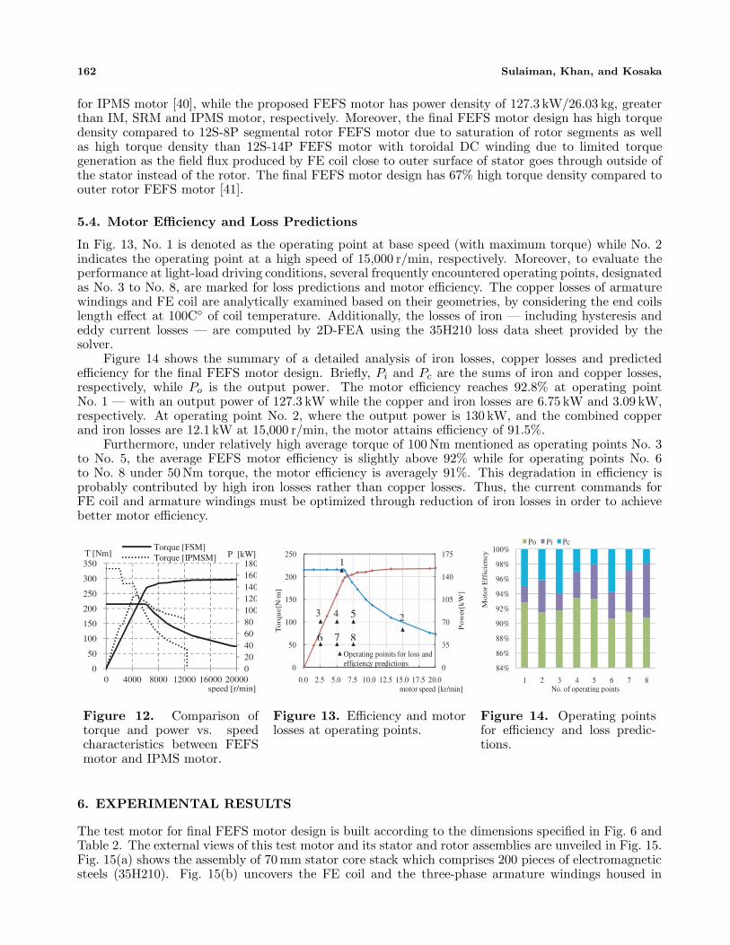
5.4. Motor Efficiency and Loss Predictions
In Fig. 13, No. 1 is denoted as the operating point at base speed (with maximum torque) while No. 2indicates the operating point at a high speed of 15,000 r/min, respectively. Moreover, to evaluate theperformance at light-load driving conditions, several frequently encountered operating points, designatedas No. 3 to No. 8, are marked for loss predictions and motor efficiency. The copper losses of armaturewindings and FE coil are analytically examined based on their geometries, by considering the end coilslength effect at 100C◦ of coil temperature. Additionally, the losses of iron — including hysteresis andeddy current losses — are computed by 2D-FEA using the 35H210 loss data sheet provided by thesolver.
Figure 14 shows the summary of a detailed analysis of iron losses, copper losses and predictedefficiency for the final FEFS motor design. Briefly, Pi and Pc are the sums of iron and copper losses,respectively, while Po is the output power. The motor efficiency reaches 92.8% at operating pointNo. 1 — with an output power of 127.3 kW while the copper and iron losses are 6.75 kW and 3.09 kW,respectively. At operating point No. 2, where the output power is 130 kW, and the combined copperand iron losses are 12.1 kW at 15,000 r/min, the motor attains efficiency of 91.5%.
Furthermore, under relatively high average torque of 100 Nm mentioned as operating points No. 3to No. 5, the average FEFS motor efficiency is slightly above 92% while for operating points No. 6to No. 8 under 50 Nm torque, the motor efficiency is averagely 91%. This degradation in efficiency isprobably contributed by high iron losses rather than copper losses. Thus, the current commands forFE coil and armature windings must be optimized through reduction of iron losses in order to achievebetter motor efficiency.
020406080100120140160180
0
50
100
150
200
250
300
350
0 4000 8000 12000 16000 20000
P [kW]T [Nm]
speed [r/min]
Torque [FSM]Torque [IPMSM]
Figure 12. Comparison oftorque and power vs. speedcharacteristics between FEFSmotor and IPMS motor.
0
35
70
105
140
175
0
50
100
150
200
250
0.0 2.5 5.0 7.5 10.0 12.5 15.0 17.5 20.0
Po
wer
[kW
]
To
rqu
e[N⋅m
]
motor speed [kr/min]
Operating poinits for loss and efficiency predictions
1
2 3 4 5
6 7 8
Figure 13. Efficiency and motorlosses at operating points.
84%
86%
88%
90%
92%
94%
96%
98%
100%
1 2 3 4 5 6 7 8
Mo
tor
Eff
icie
ncy
No. of operating points
Po Pi Pc
Figure 14. Operating pointsfor efficiency and loss predic-tions.
6. EXPERIMENTAL RESULTS
The test motor for final FEFS motor design is built according to the dimensions specified in Fig. 6 andTable 2. The external views of this test motor and its stator and rotor assemblies are unveiled in Fig. 15.Fig. 15(a) shows the assembly of 70 mm stator core stack which comprises 200 pieces of electromagneticsteels (35H210). Fig. 15(b) uncovers the FE coil and the three-phase armature windings housed in

Progress In Electromagnetics Research B, Vol. 71, 2016 163
Test motor Torque measurement system
Dynamometer
(a) (b) (c) (d)
Figure 15. Photographs of test motor, (a) assembly of stator core, (b) assembly of stator, (c) assemblyof stator and rotor, (d) Experimental bench.
24 slots. The entire motor assembly completed with the rotor core is displayed in Fig. 15(c). Theprototype of the final FEFS motor is enclosed by water cooling jacket and experimental bench for datameasurement is illustrated in Fig. 15(d).
6.1. Measured Induced Voltage Waveforms at 1000 r/min
Under the conditions of all three-phase armature windings being in an open circuit and operatedat a speed of 1,000 r/min, the changes of induced voltage waveforms with varying FE coil mmf aremeasured. The comparison between 2D-FEA-computed and measured induced voltage waveforms isshown in Fig. 16. The twelve FE coils are connected in series, and there are 44 turns per FE coil. Themmf per FE coil — in the unit of AT — is calculated from the DC current of FE coil multiplied by44 turns. To be precise, the mmf of FE coil at 524 AT, 1048 AT, 1571 AT, and 2200 AT correspondsrespectively to FE coil current density of 5 A/mm2, 10 A/mm2, 15 A/mm2, and 21 A/mm2. Positively,the 2D-FEA-computed and measured induced voltage waveforms are found to be in good agreement.
6.2. Armature Coil Current Versus Torque Characteristics
The curves of armature coil current versus measured torque are plotted in Fig. 17. During the test, thearmature current varies from 0 to 154.8 Arms, that is about 60% of the maximum armature current of260 Arms achieved at the design stage — a constraint attributable to the limit of maximum invertercurrent. As for FE coil mmf, its variation ranges from 0 to 2200 AT, as in the induced voltagemeasurement. Overall, the calculated torque curve — obtained by 2D-FEA — coincides well with
Figure 16. Measured induced voltage waveformsat 1,000 rev/min.
0
20
40
60
80
100
120
140
0 40 80 120 160
Tor
que[
Nm
]
Armature current[Arms]
524[AT] 1048[AT] 1571[AT] 2200[AT]
Figure 17. Measured armature current vs.torque characteristics.

164 Sulaiman, Khan, and Kosaka
the actual design. The proposed final FEFS motor design has produced average torque of 122 Nm atarmature current of 154.8 Arms and FE coil mmf of 2200 AT. In slanted air-gap structure of an IPMSmotor with brushless field excitation for application in HEV [42], the output torque of 132.45 Nm wasobtained during the test at maximum armature current of 200 A and FE coil mmf of 4325 AT. The IPMSmotor with brushless excitation has utilized almost double FE coil mmf of FEFS motor to produce 7.8%high average torque compared to FEFS motor. Moreover, the consumption of rare earth PM and highFE coil mmf by IPMS motor with brushless field excitation has raised the cost and copper losses.
Being limited by maximum inverter current, the experimental torque curves at FE coil of 2200 ATare estimated by extrapolating the graph up to maximum armature current of 260 Arms. The resultantmaximum torque is about 205 Nm, which is close enough to the target of 210 Nm, as calculated from2D-FEA.
7. CONCLUSION
A three-phase 12slot-10pole FEFS motor employing salient pole rotor for traction drive applicationsis investigated in this paper. The design, optimization and performance analysis of low cost FEFSmotor is presented. For an accurate analysis of the proposed FEFS motor and to perform thesensitive analysis, a 2D-FEA is used. The final design of FEFS motor is built and tested. The finalmotor design successfully fulfils the required power and maximum torque under specific restrictionsfor the targeted HEV application. Comparison between the 2D-FEA predicted values and measuredresults demonstrates good agreement that clearly confirms the effectiveness of design optimization andapproach. Furthermore, the final design FEFS motor achieves power density of 4.8 kW/kg, greaterthan IM, SRM and IPMS motor, respectively. To conclude, the proposed motor is undoubtedly a goodcandidate of non-PM motor for future HEV drive.
ACKNOWLEDGMENT
This work was supported by FRGS (Vot 1508) under Ministry of Education Malaysia, and UniversityTun Hussein Onn Malaysia (UTHM), Batu Pahat, Johor, Malaysia.
REFERENCES
1. Sulaiman, E., T. Kosaka, and N. Matsui, “Design and performance of 6-slot 5-pole PMFSMwith hybrid excitation for hybrid electric vehicle applications,” International Power ElectronicsConference (IPEC), 1962–1968, 2010.
2. Mahmoudi, A., N. A. Rahim, and H. W. Ping, “Axial-flux permanent-magnet motor designfor electric vehicle direct drive using sizing equation and finite element analysis,” Progress InElectromagnetics Research, Vol. 122, 467–496, 2012.
3. Chan, C. C., “The state of the art of electric, hybrid, and fuel cell vehicles,” Proc. IEEE, Vol. 95,No. 4, 704–718, Apr. 2007.
4. Zhao, W., M. Cheng, J. Ji, and R. Cao, “Electromagnetic analysis of a modular flux-switchingpermanent-magnet motor using finite-element method,” Progress In Electromagnetics Research B,Vol. 43, 239–253, 2012.
5. Emadi, J., L. Young, and K. Rajashekara, “Power electronics and motor drives in electric, hybridelectric, and plug-in hybrid electric vehicles,” IEEE Trans. Ind. Electron., Vol. 55, No. 6, 2237–2245,Jan. 2008.
6. Gao, D. W., C. Mi, and A. Emadi, “Modeling and simulation of electric and hybrid vehicles,” Proc.IEEE, Vol. 95, No. 4, 729–745, Apr. 2007.
7. Mizutani, R., “The present state and issues of the motor employed in Toyota HEVs,” Proc. of the29th Symposium on Motor Technology in Techno-Frontier, E3-2-1-E3-2-20, 2009 (in Japanese).
8. Chan, C. C., “The state of the art of electric and hybrid vehicles,” Proc. IEEE, Vol. 90, No. 2,247–275, Feb. 2002.
9. Jahns, T. M. and V. Blasko, “Recent advances in power electronics technology for industrial andtraction machine drives,” Proc. IEEE, Vol. 89, No. 6, 963–975, Jun. 2001.

Progress In Electromagnetics Research B, Vol. 71, 2016 165
10. Wang, T., P. Zheng, and S. Cheng, “Design characteristics of the induction motor used for hybridelectric vehicle,” IEEE Trans. Magn., Vol. 41, No. 1, 505–508, Jan. 2005.
11. Malan, J. and M. J. Kamper, “Performance of a hybrid electric vehicle using reluctance synchronousmachine technology,” IEEE Trans. Ind. Appl., Vol. 37, No. 5, 1319–1324, Sep./Oct. 2001.
12. Rahman, K. M., B. Fahimi, G. Suresh, A. V. Rajarathnam, and M. Ehsani, “Advantages of switchedreluctance motor applications to EV and HEV: Design and control issues,” IEEE Trans. Ind. Appl.,Vol. 36, No. 1, 111–121, Jan./Feb. 2000.
13. Xue, X. D., K. W. E. Cheng, T. W. Ng, N. C. Cheung, “Multi-objective optimization design of in-wheel switched reluctance motors in electric vehicles,” IEEE Trans. Ind. Electron., Vol. 57, No. 9,2980–2987, Sep. 2010.
14. Geldhof, K. R., A. P. M. Van den Bossche, J. A. Melkebeek, “Rotor-position estimation of switchedreluctance motors based on damped voltage resonance,” IEEE Trans. Ind. Electron., Vol. 57, No. 9,2954–2960, Sep. 2010.
15. Kano, Y. and T. Mano, “Design of slipring-less winding excited synchronous motor for hybridelectric vehicle,” IEEE 15th International Conference on Electrical Machines and Systems(ICEMS), 1–5, 2012.
16. Kamiya, M., “Development of traction drive motors for the Toyota hybrid systems,” IEEJ Trans.Ind. Appl., Vol. 126, No. 4, 473–479, Apr. 2006.
17. Sulaiman, E., T. Kosaka, and N. Matsui, “Design and analysis of high-power/high-torque densitydual excitation switched-flux machine for traction drive in HEVs,” Renewable and SustainableEnergy Reviews, Vol. 34, 517–524, 2014.
18. Dorrell, D., L. Parsa, and I. Boldea, “Automotive electric motors, generators, and actuatordrive systems with reduced or no permanent magnets and innovative design concepts,” IEEETransactions on Industrial Electronics, Vol. 61, No. 10, 5693–5694, Oct. 2014.
19. Pollock, C. and M. Wallace, “The flux switching motor, a DC motor without magnets or brushes,”Proc. Conf. Rec. IEEE IAS Annual Meeting, Vol. 3, 1980–1987, 1999.
20. Pollock, H., C. Pollock, R. T. Walter, and B. V. Gorti, “Low cost, high power density,flux switchingmachines and drives for power tools,” Proc. Conf. Rec. IEEE IAS Annual Meeting, 1451–1457, 2003.
21. Pollock, C., H. Pollock, and M. Brackley “Electronically Controlled flux switching motors: Acomparison with an induction motor driving an axial fan,” Proc. Conf. Rec. IEEE IAS AnnualMeeting, 2465–2470, 2003.
22. Pollock, C., H. Pollock, R. Barron, J. R. Coles, D. Moule, A. Court, and R. Sutton “Flux-switching motors for automotive applications,” IEEE Trans. Ind. Appl., Vol. 42, No. 5, 1177–1184,Sep./Oct. 2006.
23. Bangura, J. F., “Design of high-power density and relatively high efficiency fluxswitching motor,”IEEE Trans. Energy Convers., Vol. 21, No. 2, 416–424, Jun. 2006.
24. Zho, Y. J. and Z. Q. Zhu, “Comparison of low-cost single-phase wound-field switched-fluxmachines,” 2013 IEEE International Electric Machines & Drives Conference (IEMDC), 1275–1282,2013.
25. Omar, M. F., E. Sulaiman, and H. A. Soomro, “New topology of single-phase field excitation fluxswitching machine for high density air-condition with segmental rotor,” Applied Mechanics andMaterials, Vol. 695, 783–786, 2015.
26. Husin, Z. A., E. Sulaiman, F. Khan, M. M. A. Mazlan, and S. N. U. Zakaria, “ Design of low costsingle phase 8S-8P field excitation flux switching motor for hybrid electric vehicles,” Journal ofApplied Science and Agriculture, Vol. 9, No. 18, 126–131, 2014.
27. Chen, J. T., Z. Q. Zhu, S. Iwasaki, and R. Deodhar, “Low cost flux-switching brushless ACmachines,” Proc. IEEE Vehicle Power and Propulsion Conf., VPPC 2010, 1–6, Lille, France,Sep. 2010.
28. Zulu, A., B. C. Mecrow, and M. Armstrong, “Topologies for three-phase wound field segmented-rotor flux switching machines,” 5th IET International Conference on Power Electronics, Machinesand Drives (PEMD), 1–6, 2010.

166 Sulaiman, Khan, and Kosaka
29. Sulaiman, E., M. F. M. Teridi, Z. A. Husin, M. Z. Ahmad, and T. Kosaka, “Performance comparisonof 24S-10P and 24S-14P field excitation flux switching machine with single DC-coil polarity,” Proc.on Int. Power Eng. & Optimization Conf., 46–51, 2013.
30. Tang, Y., J. J. H. Paulides, T. E. Motoasca, and E. A. Lomonova, “Flux-switching machine withDC excitation,” IEEE Transactions on Magnetics, Vol. 48, No. 11, 3583–3586, Nov. 2012.
31. Fei, W., P. Chi, K. Luk, S. Member, J. X. Shen, Y. Wang, and M. Jin, “A novel permanent-magnetflux switching machine with an outer-rotor configuration for in-wheel light traction applications,”IEEE Transactions on Industry Applications, Vol. 48, No. 5, 1496–1506, 2012.
32. Othman, S. M. N. S. and E. Sulaiman, “Design study of 3-phase field-excitation fluxswitching motor with outer-rotor configuration,” IEEE 8th International Power Engineering andOptimization Conference (PEOCO2014), 230–234, Mar. 2014.
33. Lukic, S. M. and A. Emadi, “State-switching control technique for switched reluctance motor drives:Theory and implementation,” IEEE Trans. Ind. Electron., Vol. 57, No. 9, 2932–2938, Sep. 2010.
34. Demerdash, N. A. and J. F. Bangura, “Characterization of induction motors in adjustable-speeddrives using a time-stepping coupled finite-element state-space method including experimentalvalidation,” IEEE Trans. Ind. Appl., Vol. 35, No. 4, 790–802, Aug. 1999.
35. Bangura, J. F. and N. A. Demerdash, “Simulation of inverter-fed induction motor drives withpulse-width modulation by a time-stepping coupled finite element flux linkage-based state spacemodel,” IEEE Trans. Energy Convers., Vol. 14, No. 3, 518–525, Sep. 1999.
36. Hameyer, K., F. Henrotte, H. V. Sande, G. Deliege, H. De Gersem, “Finite element models inelectrical machine design,” Proceeding of Int. Conf. CB Mag, 13, Gramado, Brasil, Nov. 2002.
37. Sulaiman, E., T. Kosaka, and N. Matsui, “Design optimization and performance of a novel 6-Slot5-Pole PMFSM with hybrid excitation for hybrid electric vehicle,” IEE J. Trans. on Industry Appl.,Vol. 132, No. 2, Sec. D, 211–218, 2012.
38. Zulu, A., B. C. Mecrow, and M. Armstrong, “A wound-field three-phase flux-switching synchronousmotor with all excitation sources on the stator,” IEEE Trans. Ind. Appl., Vol. 46, No. 6, 2363–2371,Nov. 2010.
39. Oguz, Y. and M. Dede, “Speed estimation of vector controlled squirrel cage asynchronous motorwith artificial neural networks,’ Energy Conversion and Management, Vol. 52, No. 1, 675–686, 2011.
40. Yang, Z., F. Shang, I. P. Brown, and M. Krishnamurthy, “Comparative study of interior permanentmagnet, induction, and switched reluctance motor drives for EV and HEV applications,” IEEETransactions on Transportation Electrification, Vol. 1, No. 3, 245–254, Oct. 2015.
41. Khan, F., E. Sulaiman, and M. Z. Ahmad, “Review of switched flux wound-field machinestechnology,” IETE Technical Review, Jun. 2016, DOI: 10.1080/02564602.2016.1190304.
42. Lee, S. T. and L. M. Tolbert, “Study of various slanted air-gap structures of interior permanentmagnet synchronous motor with brushless field excitation,” IEEE Energy Conversion Congress andExposition, 1686–1692, Atlanta, GA, 2010.