Embed Size (px)
Citation preview
- 1 -
Fibre Reinforced Concrete Beams Subjected to Air Blast Loading
Johan Magnusson
Ph.D. student
Division of Concrete Structures
Royal Institute of Technology
SE-100 44 Stockholm, Sweden
E-mail: [email protected]
ABSTRACT
This paper involves testing of steel fibre reinforced concrete
(SFRC) beams subjected to static and dynamic loads. The
dynamic load was generated by a detonating explosive charge.
The work focused upon studying the mechanical behaviour of
the beams. The concrete compressive strength varied between
36 MPa and 189 MPa with a fibre content of 1.0 percent by
volume. Two different fibre lengths having constant length-to-
diameter ratio were employed. The experimental results indicate
that the toughness is reduced when increasing the compressive
strength and the dynamic strength is higher than the
corresponding static strength.
Key words: Steel fibres, high strength concrete, air blast
loading, toughness.
1. INTRODUCTION
In society, a large number of reinforced concrete structures exist as a natural part of the
infrastructure and the urban environment or as various types of civilian and military facilities.
Explosions due to civilian accidents, from high explosives or due to weapons effects result in
extreme loading conditions on facilities such as buildings and protective structures. Such
explosions at or near the ground surface mainly generate blast overpressures and fragments
generated by the explosion. The most important issue in the dynamic response of structures in
urban environments is usually prescribed to the blast overpressure, even though the effects of
impacting fragments may also cause severe damage.
Plain concrete is characterised by a relatively low tensile strength and brittle tensile failure.
However, the ductility of the concrete can be improved considerably by adding steel fibres to
the matrix. As steel fibre reinforced concrete (SFRC) is subjected to an increasing load in e.g.
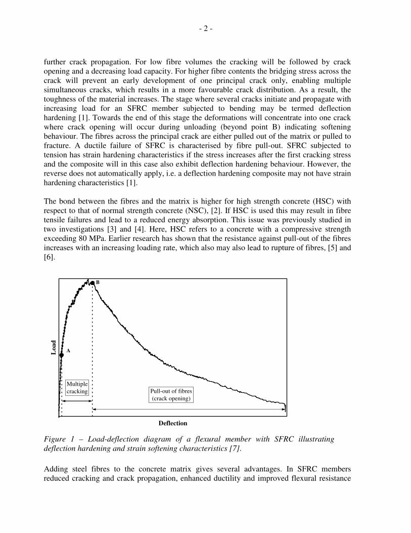
bending, cracking of the matrix is the first step towards fracture of the material. This
corresponds to point A in Figure 1. Prior to this point the stress is transferred by both the
matrix and the fibres. The fibres provide bridging stresses across the crack, which may arrest
- 2 -
further crack propagation. For low fibre volumes the cracking will be followed by crack
opening and a decreasing load capacity. For higher fibre contents the bridging stress across the
crack will prevent an early development of one principal crack only, enabling multiple
simultaneous cracks, which results in a more favourable crack distribution. As a result, the
toughness of the material increases. The stage where several cracks initiate and propagate with
increasing load for an SFRC member subjected to bending may be termed deflection
hardening [1]. Towards the end of this stage the deformations will concentrate into one crack
where crack opening will occur during unloading (beyond point B) indicating softening
behaviour. The fibres across the principal crack are either pulled out of the matrix or pulled to
fracture. A ductile failure of SFRC is characterised by fibre pull-out. SFRC subjected to
tension has strain hardening characteristics if the stress increases after the first cracking stress
and the composite will in this case also exhibit deflection hardening behaviour. However, the
reverse does not automatically apply, i.e. a deflection hardening composite may not have strain
hardening characteristics [1].
The bond between the fibres and the matrix is higher for high strength concrete (HSC) with
respect to that of normal strength concrete (NSC), [2]. If HSC is used this may result in fibre
tensile failures and lead to a reduced energy absorption. This issue was previously studied in
two investigations [3] and [4]. Here, HSC refers to a concrete with a compressive strength
exceeding 80 MPa. Earlier research has shown that the resistance against pull-out of the fibres
increases with an increasing loading rate, which also may also lead to rupture of fibres, [5] and
[6].
Deflection
Lo
ad
Pull-out of fibres
(crack opening)
Multiple
cracking
A
B
Figure 1 – Load-deflection diagram of a flexural member with SFRC illustrating
deflection hardening and strain softening characteristics [7].
Adding steel fibres to the concrete matrix gives several advantages. In SFRC members
reduced cracking and crack propagation, enhanced ductility and improved flexural resistance
- 3 -
may be expected. Earlier research [8] indicated enhancements in the shear strength of
conventionally reinforced HSC beams subjected to air blast loading. The diagonal shear failure
of the beams without any fibres could be prevented by adding fibres to the concrete.
Furthermore, introduction of steel fibres turned out to have a positive effect on the
compressive failure of high strength concrete beams [9]. The presence of steel fibres may have
a confining effect on the compression zone, which contributes to a more ductile failure event
as the concrete is crushed during bending. In this way it is also possible to obtain a larger
residual strength in the beam in the post-peak stage of behaviour.
The objective of this work was to study the mechanical behaviour of SFRC beams subjected to
air blast loading. The work focused upon studying the deformation capacity, the load capacity
and the toughness of SFRC beams.
2. EXPERIMENTAL PROGRAM
A total of 40 beams were tested, of which 22 beams were subjected to air blast loading and 18
to static loading. The test program comprised three concrete strengths and two steel fibre
lengths, as presented in Table 1. The concrete compressive strength was determined on
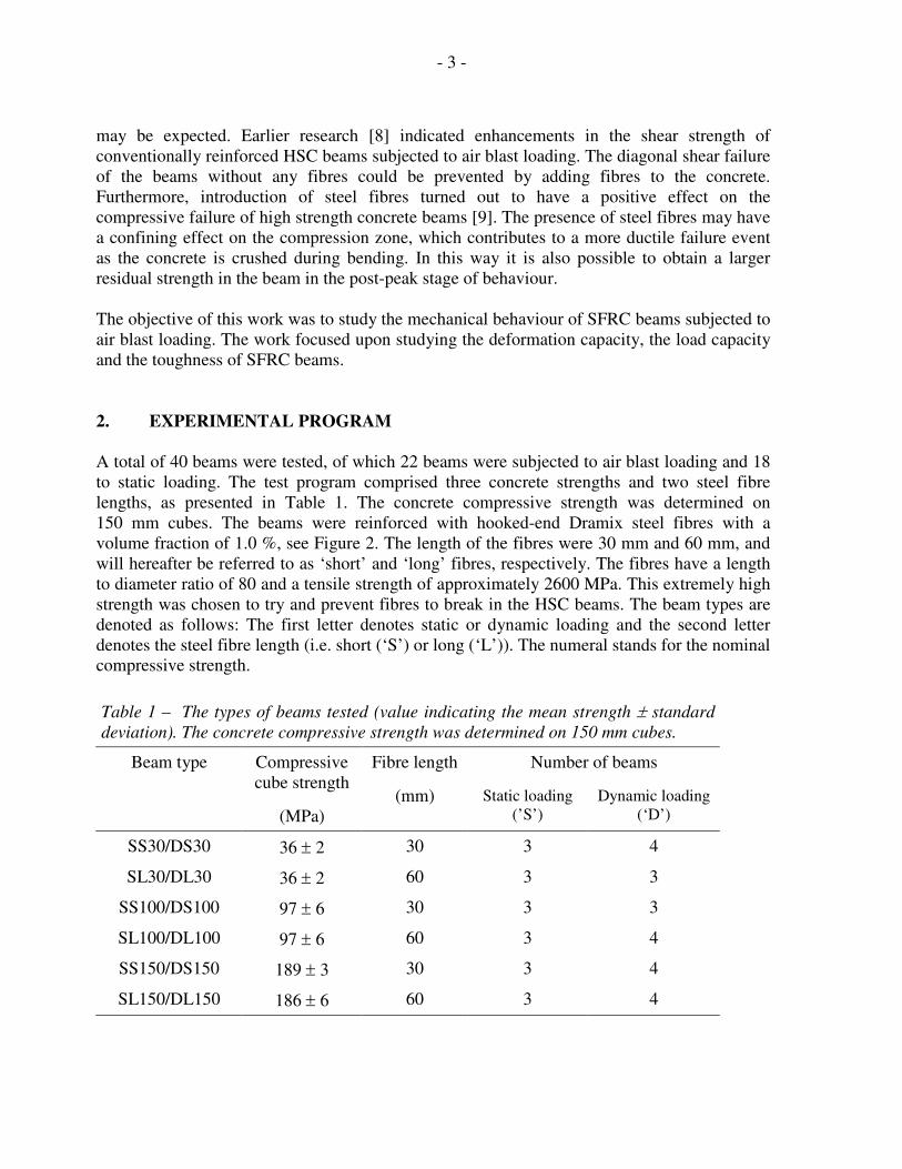
150 mm cubes. The beams were reinforced with hooked-end Dramix steel fibres with a
volume fraction of 1.0 %, see Figure 2. The length of the fibres were 30 mm and 60 mm, and
will hereafter be referred to as ‘short’ and ‘long’ fibres, respectively. The fibres have a length
to diameter ratio of 80 and a tensile strength of approximately 2600 MPa. This extremely high
strength was chosen to try and prevent fibres to break in the HSC beams. The beam types are
denoted as follows: The first letter denotes static or dynamic loading and the second letter
denotes the steel fibre length (i.e. short (‘S’) or long (‘L’)). The numeral stands for the nominal
compressive strength.
Table 1 – The types of beams tested (value indicating the mean strength ± standard
deviation). The concrete compressive strength was determined on 150 mm cubes.
Number of beams Beam type Compressive
cube strength
(MPa)
Fibre length
(mm) Static loading
(’S’)
Dynamic loading
(‘D’)
SS30/DS30 36 ± 2 30 3 4
SL30/DL30 36 ± 2 60 3 3
SS100/DS100 97 ± 6 30 3 3
SL100/DL100 97 ± 6 60 3 4
SS150/DS150 189 ± 3 30 3 4
SL150/DL150 186 ± 6 60 3 4
- 4 -
Lf = 60 mm
Lf = 30 mm
Figure 2 – Steel fibres with end hooks used in the tests.
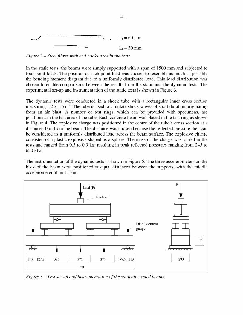
In the static tests, the beams were simply supported with a span of 1500 mm and subjected to
four point loads. The position of each point load was chosen to resemble as much as possible
the bending moment diagram due to a uniformly distributed load. This load distribution was
chosen to enable comparisons between the results from the static and the dynamic tests. The
experimental set-up and instrumentation of the static tests is shown in Figure 3.
The dynamic tests were conducted in a shock tube with a rectangular inner cross section
measuring 1.2 x 1.6 m2. The tube is used to simulate shock waves of short duration originating
from an air blast. A number of test rings, which can be provided with specimens, are
positioned in the test area of the tube. Each concrete beam was placed in the test ring as shown
in Figure 4. The explosive charge was positioned in the centre of the tube’s cross section at a
distance 10 m from the beam. The distance was chosen because the reflected pressure then can
be considered as a uniformly distributed load across the beam surface. The explosive charge
consisted of a plastic explosive shaped as a sphere. The mass of the charge was varied in the
tests and ranged from 0.3 to 0.9 kg, resulting in peak reflected pressures ranging from 245 to
630 kPa.
The instrumentation of the dynamic tests is shown in Figure 5. The three accelerometers on the
back of the beam were positioned at equal distances between the supports, with the middle
accelerometer at mid-span.
187.5110 375
1720
375 375
Load cell
Load (P)
Deflection gauge
187.5 110 290
160
P
Figure 3 – Test set-up and instrumentation of the statically tested beams.
Displacement
gauge
- 5 -
10 m
1
2
3 4
1.5 m1.6 m
1) Explosive charge
2) Concrete beam
3) Shock tube
4) Test ring
Figure 4 – Longitudinal section of the shock tube with the specimen assembled to the
tube end and position of the explosive charge.
Pressure gauge
A
A
Accelerometer
Deflection gauge
Load cell
A-A
150
0
200
Figure 5 – Instrumentation of the dynamically tested beams.
- 6 -
3. RESULTS
3.1 General
Some general observations from both the static and the air blast tests will be commented on
first. The main flexural failure mechanism was by fibre pull-out for all beams. For beams of
concrete grade 150 a combination of fibre pull-out and fibre fractures were observed, while no
fibres were observed to break in beams of concrete grades 30 and 100. For beams of grade 150
the portion of fibre fractures in the failure surface was estimated to about 5 % in the static tests
and the remaining part was pulled out of the matrix. This failure mode applies to beams
containing both fibre types. The most probable cause for rupturing of fibres is the increase in
bond strength of the HSC beams in relation to the NSC beams.
In the air blast tests of the beams of concrete grade 150, the amount of fibre fracture was
estimated to about 7 % in beams containing short fibres and 12 % in beams with long fibres.
Thus, a tendency towards an increased amount of fibre fractures was observed in the dynamic
tests compared to beams loaded statically, which is in agreement with earlier investigations [5]
and [6]. As a result of these findings, it can be concluded that the risk of brittle failure of fibre
reinforced concrete at static and dynamic loading is higher for HSC than NSC.
3.2 Static tests
The load-deflection diagrams for all the tests where the beams were subjected to static loading
are presented in Figure 6. The load in these diagrams refers to the total applied load, i.e. the
sum of the four point loads. As these figures illustrate, there is a relatively large scatter of the
curves from the same beam types, which can be attributed to an uneven fibre distribution and
orientation in the beams as observed at the failure surfaces after the tests. The failure surfaces
exhibited clumps of fibres and also areas without fibres. As expected, the beams with long
fibres exhibited larger deformations before failure than the beams with short fibres. Compared
to short fibres, long fibres provide bridging stresses across larger cracks, which allows for
larger deformations of the beams. This applies to beams where fibres are pulled out of the
matrix since fractured fibres do not allow for large deformations. The tests also show that the
load capacity is increasing with increasing concrete strength, which is to be expected.
The crack load of SFRC with low fibre content is approximately the same as for plain
concrete. However, for large fibre contents there will also be a certain effect of the fibres on
the crack load. In these tests, the fibre content was too low to have any noticeable effect on the
crack load.
- 7 -
0
20
40
60
80
100
120
0 5 10 15 20 25 30 35 40 45 50 55
Deflection (mm)
Lo
ad
(k
N)
SL30 beams
SS30 beams
0
20
40
60
80
100
120
0 5 10 15 20 25 30 35 40 45 50 55Deflection (mm)
Lo
ad
(k
N)
SL100 beams
SS100 beams
0
20
40
60
80
100
120
0 5 10 15 20 25 30 35 40 45 50 55
Deflection (mm)
Lo
ad
(k
N)
SL150 beams
SS150 beams
Figure 6 – Load-deflection diagrams of all beams subjected to static loading.
- 8 -
In the static tests all beams exhibited strain hardening characteristics, i.e. the load increased
further after the first crack appeared, which enabled multiple cracking to take place. The crack
load of each beam was determined from the corresponding load-deflection diagram at the point
where the flexural stiffness was significantly reduced and, consequently, where strain
hardening of the concrete commences, see Figure 7. Figure 8 presents a comparison between
the crack load and the peak load for each type of beam in the static tests. The numerals above
the bars indicate the ratio between the peak load and the cracking load. These numbers differ
somewhat from those in a corresponding figure in [3] due to re-evaluation of the results. As
Figure 8 shows, beams of concrete grades 30 and 100 with long fibres showed a larger peak to
crack load ratio than similar beams with short fibres. The largest strain hardening effect was,
however, obtained for the beams with short fibres of concrete grade 150. Consequently, the
tests indicate that long fibres are less efficient with respect to strain hardening with increasing
concrete strength. The beams with long fibres appeared to be more sensitive to fibre fractures
than beams with short fibres.
The crack distribution along the longitudinal axis of the beams was similar for all the statically
loaded beams in this investigation. A larger number of cracks were, however, observed on
beams of NSC containing long fibres compared to beams of this concrete grade with short
fibres and beams of higher strength. The number of cracks was somewhat reduced in the
dynamic tests in relation to the static tests for beam of the highest concrete grade.
SS150-1
0
20
40
60
80
100
120
140
0 1 2 3 4 5 6 7 8 9 10
Deflection (mm)
Lo
ad
(k
N)
Crack load
Figure 7 Determination of the crack load based on load-deflection diagram.
- 9 -
1.56
1.74
1.51
2.45
1.94
0
20
40
60
80
100
120
SS30 SL30 SS100 SL100 SS150
Beam type
Lo
ad
(k
N)
Crack load
Maximum load
Figure 8 – Maximum static load and crack load taken as the mean value of three tests.
The numerals above the bars indicate the ratio between maximum load and crack load.
The toughness index of the beams in the static tests was calculated in order to quantify the
behaviour of the different beams. The toughness index was estimated as the ratio between the
area under the whole load-deflection curve and the area under the elastic part of the curve.
Figure 9 presents the mean values of the beam toughness indices. The results clearly indicate
that the ductility is reduced at higher concrete strengths and also that the positive effects of
long fibres is reduced with increasing concrete strength. The toughness of beams of the highest
concrete grade was only slightly larger for beams with long fibres than for beams with short
fibres. This significant reduction in toughness with increasing concrete strength can also be
observed in the load-deflection curves in Figure 6. The softening part of the curves become
steeper for the HSC beams compared to the NSC beams, which is indicating a more brittle
post-peak load response.
- 10 -
0
50
100
150
200
250
300
SS30 SL30 SS100 SL100 SS150
Beam type
To
ug
hn
ess
ind
ex
Figure 9 – Mean values of the toughness index in the static tests for the different beam
types.
3.3 Air blast tests
In the dynamic tests, there were some difficulties to obtain a dynamic load that corresponded
to the strength of the beam, especially for beams of concrete grade 150. The tests showed that
the beam would either develop small deformations with a few cracks or would completely
break into two parts. This is due to the fact that the beam will be accelerated by the relatively
large dynamic pressure over the whole beam surface. The beam will thereby obtain a certain
kinetic energy, which needs to be absorbed by the beam and converted into internal energy by
concrete strains, cracking and fibre pull-out (or fractures). The static tests showed that the
beams of grade 150 will have a strain hardening behaviour and the peak load will in most
cases be reached at deflections around 4–8 mm. The peak load will be directly followed by a
softening branch, which reduces the beam’s ability to transfer load with an increasing
deflection. The beams of grade 150 failed in a more brittle manner compared to beams of
grades 30 and 100 as already discussed in section 3.2. With this type of behaviour the beam
will be very sensitive to relatively small increases in pressure and impulse density. The
impulse density is defined as the integral of the pressure-time curve and is together with the
pressure levels an important measure of the load on structures.
The beams would not be as sensitive to changes in the dynamic load with conventional tensile
reinforcement since the load carrying capacity then would not drop as quickly after the peak
load was reached. This behaviour was investigated in [8]–[10]. Figure 10 shows the reflected
- 11 -
pressures and impulse densities for the different air blast tests. Tests where beams failed are
denoted with ‘F’ in this figure. A concrete beam of any of these concrete grades and with the
same fibre reinforcement will have a pressure and impulse capacity of a magnitude between
the corresponding beams that did not fail and beams that failed.
0
100
200
300
400
500
600
700
0 1 2 3 4 5
Reflected impulse density (kPas)
Ref
lect
ed p
ress
ure
(k
Pa)
DS30
DL30
DS100
DL100
DS150
DL150
F
F
F
F
F
F
F
F
F
F
F
Figure 10 – Reflected pressure and impulse density from the air blast tests. ‘F’ in the figure
denotes beam failure.
One of the main objectives with this investigation was to evaluate and compare the load
capacity of the dynamically and statically tested beams. For this purpose, the inertia of the
beams had to be evaluated and for this a modified equivalent single-degree of freedom
(SDOF) system was used. A method for determining the load capacity of structural members
subjected to blast loads based on an SDOF system was reviewed in [11]. Usually in equivalent
SDOF calculations of structural elements one needs to determine the equivalent values of the
mass, the stiffness and the load, respectively. Here, only the equivalent mass of the beams was
determined, i.e. the total mass was substituted by an equivalent mass acting at the centre of the
beam. The registered pressure was assumed as acting as an evenly distributed dynamic load
over the surface of the beam and the flexural stiffness was assumed to be constant along the
whole beam.
The magnitude of the equivalent mass was determined in such a way that the kinetic energy of
the beam centre corresponded to the real kinetic energy of the beam. The beams were further
assumed to be simply supported with a plastic hinge in the middle section, which also is the
way the beams actually responded to the dynamic load. Thus, the equivalent mass was
obtained by multiplying the total mass by a mass factor (κm) with a magnitude of ⅓, see
- 12 -
further [11]. In these calculations the registrations from the accelerometer at mid-span were
used. Hence, the load capacity (PB) of the dynamic beams was determined from the relation:
bbmbrB aMApP ⋅⋅−⋅= κ (1)
where pr is the reflected pressure, Ab the area of the beam surface, Mb the beam mass and ab
the mid-span acceleration. In these calculations, the average value of the registrations from
both pressure gauges was used.
For most of the beams there was good agreement between the curves from the simplified
calculations and the load cell registrations. Figure 11 presents an example of this for beam
DL100-2 together with the registration of the reflected overpressure. However, the load
capacity based upon the observed reactions from the load cells is probably more accurate than
that of the calculations. Therefore it was decided to use the load cell registrations as basis for
the dynamic load capacity and the flexural resistance of the beams.
The load cell registrations were evaluated by using a polynomial fit to the registrations since
the latter exhibited fluctuations, which could be relatively large in some cases, see Figure 11.
The probable reason for these fluctuations is that the beam will be excited in higher bending
modes by the dynamic overpressure. Figure 12 compares the results from the air blast tests
with those from the static tests, and the dynamic load capacity appears to be larger than the
static strength for all the beam types. The numerals above the bars indicate the dynamic to
static load capacity ratio. From these numerals, it can also be seen that the ratio between the
strengths of the dynamic and static beams is decreasing with increasing concrete strength.
Besides, as in the static tests, beams containing long fibres obtained a higher dynamic strength
compared to beams with short fibres for concrete grades 30 and 100, whereas beams with short
fibres were strongest for concrete grade 150. The dynamic load capacities in Figure 12 are
based on the mean value of three or four tests except for the beam types DL30 and DS100,
where only the results from two tests could be used.
- 13 -
(a)
-100
0
100
200
300
400
500
600
0 0,01 0,02 0,03 0,04 0,05 0,06 0,07 0,08
Time (s)
Ov
erp
ress
ure
(k
Pa
)
(b)
-20
0
20
40
60
80
100
120
140
160
180
0 0,01 0,02 0,03 0,04 0,05 0,06 0,07 0,08
Time (s)
Su
pp
ort
rea
cti
on
(k
N)
Load cells
Calculation
(c)
-20
0
20
40
60
80
100
120
140
160
180
0 0,005 0,01 0,015 0,02 0,025 0,03 0,035 0,04
Time (s)
Su
pp
ort
react
ion
(k
N)
Load cells
Poly. (Load cells)Polynomial fit
Figure 11 – Registrations of reflected overpressure (a), calculated and observed
support reactions (b) and polynomial fit to the support reactions for test with beam
DL100-2 [4].
- 14 -
1.381.95
1.59
2.73
1.94
0
20
40
60
80
100
120
140
160
180
S30 L30 S100 L100 S150
Beam type
Su
pp
ort
rea
ctio
n (
kN
)
Static tests
Dynamic tests
Figure 12 – Mean load capacities for the static and dynamic tests. The numerals above
the bars indicate the ratio between the dynamic and static load capacity.
3.4 Discussion
Even though FRC has many benefits, the traditional way of reinforcing concrete structural
elements with steel rebars is still preferred in the design of blast resistant structures. In this
paper it is experimentally shown that adding steel fibres to concrete of higher strength also
increases the ductility and strength of elements compared to plain HSC. The different tests
show, however, that the positive effects of the used fibres are reduced in relation to
conventional concrete and other solutions of fibre contents and fibre types may instead need to
be used. The long fibres were observed to be more sensitive to an increased concrete strength
and to dynamic events even if these fibres were of the same aspect ratio as the short fibres. It
may therefore be recommended to use shorter fibres with smaller aspect ratios for these
purposes. The tests presented here must also be extended to be able to draw any definite
conclusions.
The load capacity was observed to increase in the dynamic tests and the main reason can be
attributed to strain-rate effects. It is well known that both the compressive and tensile strength
of concrete is increasing with increasing strain rate [12]. In tension this is even more
accentuated for elements of SFRC due to the effect of the higher fibre pull-out resistance as
the strain rate increases as mentioned earlier in Section 1.
- 15 -
The response of a structural element subjected to dynamic loading depends not only on
structural strength but also on inertial effects, which are always present in dynamic events.
These inertial effects can be considered as eliminated in the analysis of the load cell
registrations and these registrations were therefore used as measure for the dynamic flexural
strength of the beams.
Another effect that may be present in dynamic events is the action of an arch mechanism in the
load carrying of the beams. In both static and dynamic loading this mechanism develops if the
beam ends are prevented from outward movements. A system of compressive forces is
established in the beam, which carries the load by arch action and the load capacity can be
considerably increased. In the dynamic tests, inertial effects may also contribute to a certain
arch action. The friction at the supports and the presence of the bolts may initially contribute to
some degree of restraint. However, as inertia and friction at the supports is overcome and the
beam starts to deflect this initial arch mechanism will be lost and the load will mainly be
carried by flexural resistance.
Besides, if conventionally reinforced beams are restrained against movements at the supports a
tensile membrane type of mechanism may develop at large deformations, which enhance the
load capacity. This action is provided by the steel reinforcement and could never develop in a
SFRC beam, because the steel fibres are not able to carry the same level of tensile forces as the
steel bars.
4. CONCLUSIONS AND FUTURE RESEARCH
The following conclusions could be drawn from this investigation:
• An increase in load capacity was observed in both the static tests and the air blast tests
with increasing concrete strength. The load capacity was also enhanced in the air blast
tests with respect to the static tests with observed strength increases of around
30–170 %.
• For concrete grades 30 and 100, beams with long fibres exhibited greater strain
hardening effects compared to those containing short fibres. For concrete grade 150,
however, the beams with short fibres obtained the greatest strain hardening effects.
This may be due to a larger amount of fractures for the long fibres.
• The results clearly indicate that the toughness is reduced at higher concrete strengths
and also that the positive effects of long fibres is reduced with an increasing concrete
strength. The ductility and crack distribution along the longitudinal axis of the beams
also decreased when the beams were subjected to dynamic loading. This was especially
the case for the beams of the highest concrete grade.
Steel fibre reinforced concrete has many advantages due to its crack arresting properties and
enhancements in ductility compared to plain concrete. The experimental results presented in
this paper contribute to the knowledge of how dynamically loaded structural concrete
- 16 -
members behave and may be useful in the future design of blast loaded structures. The test
program should, however, be extended to be able to draw any definite conclusions. This work
should include investigations on the effect of shorter steel fibres in high strength concrete and
the enhanced shear strength that is observed with fibres in conventionally reinforced concrete.
Such research should also include studies on the possible confinement of the compression zone
due to the presence of fibres [9] and possible size effects on the results.
ACKNOWLEDGEMENT
The Swedish Armed Forces Headquarters funded the investigations presented and referred to
in this paper. Their funding is greatly acknowledged. I also wish to express my gratitude to
The Royal Institute of Technology, Division of Concrete Structures, for making it possible to
complete this paper and also for valuable discussions with Assoc. Prof. Anders Ansell.
REFERENCES
1. Naaman, A.E., “Strain Hardening and Deflection Hardening Fiber Reinforced Cement
Composites”, Proceedings of the 4th
International RILEM Workshop (High Performance
Fiber Reinforced Cement Composites), Ann Arbor, USA, June 15–18, 2003, pp 95–113.
2. ”Concrete Handbook – Material”, AB Svensk Byggtjänst, Stockholm, 1994 (In
Swedish).
3. Magnusson, J., “Fibre Reinforced High Strength Concrete Beams Subjected to Transient
Load”, Report FOA-R--98-00808-311--SE, Stockholm, June 1998 (In Swedish with
English summary).
4. Magnusson, J., “Steel Fibre Reinforced Concrete Beams Subjected to Air Blast
Loading”, Report FOI-R--2045--SE, Stockholm, December 2006.
5. Gopalaratnam, V.S., Shah, S.P., “Properties of Steel Fiber Reinforced Concrete
Subjected to Impact Loading”, ACI Journal (83-14), 1986 pp. 117-126.
6. Stevens, D.J., et. al., “Testing of fiber Reinforced Concrete”, American Concrete
Institute, ACI SP-155, Detroit, Michigan, 1995.
7. Naaman, A.E., “SIFCON: Tailored Properties for Structural Performance”, High
Performance Fiber Reinforced Cement Composites, RILEM Proceedings 15, London,
1992, pp. 18-38.
8. Magnusson, J., Hallgren, M., “High Performance Concrete Beams Subjected to Shock
Waves from Air Blast”, Report FOA-R--00-01586-311--SE, December 2000.
9. Magnusson, J., Hallgren, H., “High Performance Concrete Beams Subjected to Shock
Waves from Air Blast, Part 2”, FOI-R--1116--SE, Tumba, 2003.
10. Hallgren M., “Flexural and Shear Capacity of Reinforced High Strength Concrete
Beams without Stirrups”, Licentiate Thesis, Bulletin 9, Royal Institute of Technology,
Department of Structural Engineering, Stockholm 1994.
- 17 -
11. Granström, S., A., “Calculation methods of blast loaded structures”,
Fortifikationsförvaltningen Rapport nr 103:18, Stockholm, 1958 (In Swedish).
12. Malvar, L.J., Crawford, J.E., “Dynamic increase factors for concrete”, 28th
Department
of Defence Explosives Safety Seminar (DDESB), Orlando FL, USA, 1998.