Embed Size (px)
Citation preview

FiberCUT ®
2D Operation Manual

PLMNL0232 REV. B Effective Date: 10/12/16 i FiberCUT® 2D Operation Manual
WARNING
WORKING AROUND HIGH-POWERED LASERS CAN BE DANGEROUS
Laser Mechanisms, Inc.’s cutting heads must be operated with the cutting head interlock switch connected. The switch must be CLOSED when the head is properly attached. In the event of a crash and the cutting head becoming dislodged from its normal operating position, the switch must be OPEN. This interlock switch must be connected in a circuit in such a way that it will immediately turn off the laser and stop all machine motion. Check the wiring diagrams for your system.
Serious personal injury and/or equipment damage can occur if the head becomes dislodged and:
The head interlock is not connected properly.
Any interlock in the Laser Mechanisms’ product or laser system is defeated.
Laser Mechanisms, Inc. assumes no responsibility or liability for interlock switches or circuits and all interlocks are the sole responsibility of the purchaser of this head.
It is the responsibility of the integrator or end user to install, connect and activate all interlocks in compliance with the applicable ANSI, CEN, DIN, etc. standard.
All wiring should be done by personnel knowledgeable in electrical wiring and in accordance with the national and local electrical codes.
DISCLAIMER
The information in this manual is subject to change without notice.
Laser Mechanisms, Inc. makes no warranty of any kind with regard to the material in this manual, including but not limited to, the warranties or merchantability and fitness for a particular purpose.
Laser Mechanisms, Inc. shall not be liable for errors contained herein or for incidental or consequential damages in connection with furnishing, performance or use of this product.
Laser Mech® is a registered trademark of Laser Mechanisms, Inc.
Corporate names and trademarks stated herein are the property of their respective companies.
COPYRIGHT
©2016 Laser Mechanisms, Inc. All rights reserved. No part of this publication may be reproduced in any form, or by any means without the prior written permission of Laser Mechanisms, Inc.
PRODUCT WARRANTY
Laser Mechanisms, Inc. warrants this product against defects in material and workmanship for a period of one year from the date of shipment from Laser Mechanisms Inc. or an authorized distributor. During the warranty period, Laser Mechanisms, Inc. will at its option, repair or replace products that prove to be defective.
For all products returned to Laser Mechanisms, Inc. for warranty service the customer must:
Call Laser Mechanisms, Inc. for a Return Material Authorization (RMA) number.
Properly pack the product with the RMA number on the outside of the package. Include in the package, all cables, and all accessories shipped with the product along with a description of the problem.
Prepay shipping charges to Laser Mechanisms, Inc.
Insure the shipment in case of loss or damage. Laser Mechanisms, Inc. will not accept any liability in case of damage or loss.
Laser Mechanisms, Inc. will pay the shipping charges, duties and taxes for the products returned to Laser Mechanisms, Inc. from outside the United States.
The foregoing warranty will not apply if damage is incurred resulting from improper or inadequate maintenance by the customer, unauthorized modifications or misuse, operation of the product outside its specifications, interlocks not connected properly, improper site preparation, parts or assemblies not supplied by Laser Mechanisms, Inc. or unauthorized repair by non-Laser Mechanisms, Inc. authorized personnel.
For complete warranty information visit our web site at www.lasermech.com.
PLMNL0232 REV. B Effective Date: 10/12/16 ii FiberCUT® 2D Operation Manual
INITIAL INSPECTION
Inspect all shipping containers for damage as soon as the device arrives. It is your responsibility, the recipient, to notify the freight company of any damage. The freight company will require you to provide the container that any goods were shipped in, all shipping documentation and a list of all damages. Photographs of the damage are helpful in settling a freight claim.
Do not return damaged goods to the factory without a Return Material Authorization Number (RMA number).
Although it is Laser Mechanisms, Inc.’s intent to insure you are up and running as soon as possible, damage incurred during shipment must be settled with the freight company before arranging for repairs or replacement. No return shipments will be accepted without an RMA number clearly printed on the outside of all shipping containers. Failure to follow this procedure could void any warranty coverage on your head. Call your sales engineer at Laser Mechanisms, Inc. for a RMA number.
Carefully remove the device from its shipping container and all packing material to avoid damage. Save all packaging material, including the sealed, padded pelican case, in the event the head requires shipping or storage.
Check all items received against the packing list to verify that all the items were received.
Please note the product you receive may differ slightly from the illustrations in this manual. While the drawings may differ, the basic procedures described within remain the same.
TERMS USED IN THIS MANUAL
WARNING: The user could be injured if the warning is not followed.
CAUTION: The device or system could be damaged if the CAUTION is not followed.
NOTE: Clarification of a step or steps.
SAFETY
WARNINGS: Follow all warnings in this manual.
SAFETY GLASSES: Everyone in the area where the laser is being used must wear laser safety glasses designed for the laser being used.
SECONDARY REFLECTIONS: Secondary reflections are dangerous; never expose any part of your body to a reflected laser beam.
INTERLOCKS: Interlocks are safety devices and should never be defeated.
ADJUSTMENTS: Always turn off or put the laser in standby before making any adjustments to beam delivery components.
BEAM DUCT: Never open any component of the beam duct while the laser is operating. Always turn the laser off before servicing any beam duct components.
MANUALS: Always read the instruction manuals before attempting to install or make adjustments to any beam delivery component.

PLMNL0232 REV. B Effective Date: 10/12/16 iii FiberCUT® 2D Operation Manual
TABLE OF CONTENTS
1 Introduction ........................................................................................................................................................1
2 Mechanical Installation and Operation ............................................................................................................2 2.1 Machine Mount ................................................................................................................................... 2
2.2 Plumbing – Water Cooling / Purge Gas / Assist Gas / Nozzle Cooling / Air Blast ............................. 2
2.3 Fiber Input ........................................................................................................................................... 3
2.3.1 QBH Fiber Clamp .............................................................................................................3
2.3.2 Fiber Orientation Adjustment ...........................................................................................4
2.4 Beam Centering .................................................................................................................................. 5
2.4.1 Beam Centering Camera .................................................................................................5
2.4.2 Manually ...........................................................................................................................8
3 Electrical Installation and Operation ................................................................................................................9 3.1 Connections ........................................................................................................................................ 9
3.2 Interface Example ............................................................................................................................. 10
3.3 Electrical Grounding and Noise ........................................................................................................ 11
3.4 Control Box Mounting ....................................................................................................................... 11
3.5 Control Box Interface ........................................................................................................................ 12
3.5.1 Terminal Block Connections ......................................................................................... 12
3.5.2 Fieldbus Connection...................................................................................................... 13
3.6 Control Box Indicator Lights .............................................................................................................. 13
4 FiberCUT® 2D Monitor .................................................................................................................................... 15 4.1 Installation ......................................................................................................................................... 15
4.1.1 Downloading FiberCUT® 2D Monitor Software ............................................................. 15
4.1.2 Installing FiberCUT® 2D Monitor Driver ........................................................................ 16
4.2 System Requirements ...................................................................................................................... 16
4.3 Using FiberCUT® 2D Monitor ............................................................................................................ 16
4.3.1 Start Up ......................................................................................................................... 16
4.3.2 System Controls ............................................................................................................ 17
4.3.3 Faults and Status Indicator ........................................................................................... 18
4.4 FiberCUT® 2D Monitor Settings ........................................................................................................ 19
4.4.1 Unlock Settings ............................................................................................................. 19
4.4.2 Aux Output .................................................................................................................... 19
4.4.3 HSU Curve .................................................................................................................... 20
4.4.4 Temperature Limits ....................................................................................................... 20

PLMNL0232 REV. B Effective Date: 10/12/16 iv FiberCUT® 2D Operation Manual
4.4.5 Focus Position ............................................................................................................... 21
4.4.6 Motor Initialization ......................................................................................................... 21
4.4.7 Process Monitor Gain .................................................................................................... 22
4.4.8 Suppress Low Purge Fault ............................................................................................ 23
4.4.9 Configuring EtherNet/IP Settings (If Equipped) ............................................................ 23
4.5 FiberCUT® 2D Monitor System Identification Information ................................................................ 24
5 Service.............................................................................................................................................................. 25 5.1 Servicing the Gas Jet Tip .................................................................................................................. 25
5.2 Servicing the Cover Glass ................................................................................................................ 26
5.3 Servicing the Breakaway Insulator ................................................................................................... 28
5.4 Servicing the Tip Assembly .............................................................................................................. 30
5.5 Removing the Fiber........................................................................................................................... 30
5.6 Servicing the Focus Lens ................................................................................................................. 31
5.7 Adjusting the Focus Lens Position Manually .................................................................................... 34
5.8 Servicing the Collimator Lens Cartridge ........................................................................................... 35
5.9 Removing the Cutting Head .............................................................................................................. 37
6 Specifications .................................................................................................................................................. 38
7 Troubleshooting .............................................................................................................................................. 39
8 Appendix A – Cleaning Optics ....................................................................................................................... 40
9 Appendix B – Coolant Specifications ........................................................................................................... 42
10 Appendix C – Assist Gas Specifications ...................................................................................................... 42
11 Appendix D – Beam Delivery Purging ........................................................................................................... 42
12 Appendix E – Fieldbus Data Mapping and Descriptions ............................................................................ 43 12.1 EtherNet I/P I/O Mapping .................................................................................................................. 43
12.2 PROFINET I/O Mapping ................................................................................................................... 44
12.3 Input, Output, and Other Descriptions .............................................................................................. 45
13 Appendix F – Recommended User-Serviceable Parts List ......................................................................... 47
14 Appendix G – Servicing the Tip Assembly ................................................................................................... 50 14.1 User Serviceable Parts List .............................................................................................................. 50
14.2 Rebuilding the Tip Assembly ............................................................................................................ 51
15 Glossary ........................................................................................................................................................... 53
PLMNL0232 REV. B Effective Date: 10/12/16 1 FiberCUT® 2D Operation Manual
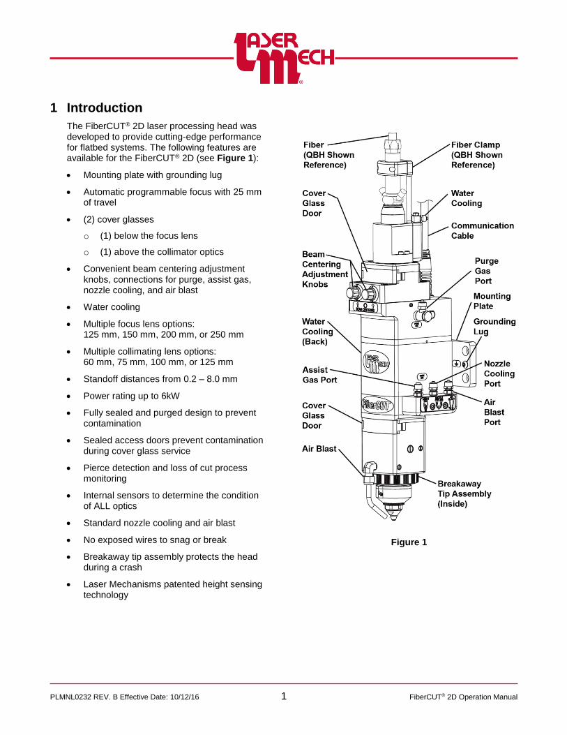
1 Introduction
The FiberCUT® 2D laser processing head was developed to provide cutting-edge performance for flatbed systems. The following features are available for the FiberCUT® 2D (see Figure 1):
Mounting plate with grounding lug
Automatic programmable focus with 25 mm of travel
(2) cover glasses
o (1) below the focus lens
o (1) above the collimator optics
Convenient beam centering adjustment knobs, connections for purge, assist gas, nozzle cooling, and air blast
Water cooling
Multiple focus lens options: 125 mm, 150 mm, 200 mm, or 250 mm
Multiple collimating lens options: 60 mm, 75 mm, 100 mm, or 125 mm
Standoff distances from 0.2 – 8.0 mm
Power rating up to 6kW
Fully sealed and purged design to prevent contamination
Sealed access doors prevent contamination during cover glass service
Pierce detection and loss of cut process monitoring
Internal sensors to determine the condition of ALL optics
Standard nozzle cooling and air blast
No exposed wires to snag or break
Breakaway tip assembly protects the head during a crash
Laser Mechanisms patented height sensing technology
Figure 1

PLMNL0232 REV. B Effective Date: 10/12/16 2 FiberCUT® 2D Operation Manual
2 Mechanical Installation and Operation
2.1 Machine Mount
The mount plate attaches directly to your 3-axis machine according to Figure 2.
Figure 2
2.2 Plumbing – Water Cooling / Purge Gas / Assist Gas / Nozzle Cooling / Air Blast
See Figure 3 and Figure 4 for line locations.
Laser head cooling specifications can be found in Appendix B.
See the manufacturer’s information for specifications on cooling the fiber.
Assist gas specification can be found in Appendix C.
Purge gas specifications can be found in Appendix D.
Figure 3

PLMNL0232 REV. B Effective Date: 10/12/16 3 FiberCUT® 2D Operation Manual
Figure 4
2.3 Fiber Input
The fiber input adapter is where the fiber optic cable plugs into the cutting head. See Figure 5. There are several standard types of industrial fiber (QBH/HLC-8, QD/LLK-D/LCA, Q5/LLK-B, and PIPA). Each of these fibers requires a unique fiber input adapter. Refer to the fiber manufacturer’s information for specific instructions.
EVERY TIME the fiber is removed and/or installed the upper cover glass MUST BE
Inspected and/or cleaned according to Appendix A.
OR
Replaced according to Section 5.2.
2.3.1 QBH Fiber Clamp
The QBH fiber clamp provides added stability to the fiber connection (see Figure 5).
1. Loosen the (2) captive M4 SHCS and remove the fiber clamp.
2. Install the fiber into the fiber input adapter according to the fiber manufacturer’s instructions.
If the water cooling fittings on the fiber interfere with the QBH fiber clamp, rotate the QBH fiber interface according to Section 2.3.2.
3. Replace the fiber clamp.
Verify the (2) alignment pins are in-line with the alignment holes.
Tighten the (2) captive M4 SHCS.
Figure 5
PLMNL0232 REV. B Effective Date: 10/12/16 4 FiberCUT® 2D Operation Manual
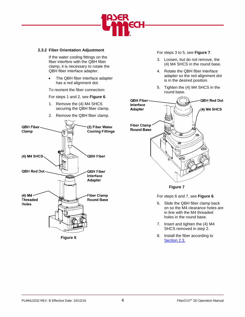
2.3.2 Fiber Orientation Adjustment
If the water cooling fittings on the fiber interfere with the QBH fiber clamp, it is necessary to rotate the QBH fiber interface adapter.
The QBH fiber interface adapter has a red alignment dot.
To reorient the fiber connection:
For steps 1 and 2, see Figure 6.
1. Remove the (4) M4 SHCS securing the QBH fiber clamp.
2. Remove the QBH fiber clamp.
Figure 6
For steps 3 to 5, see Figure 7.
3. Loosen, but do not remove, the (4) M4 SHCS in the round base.
4. Rotate the QBH fiber interface adapter so the red alignment dot is in the desired position.
5. Tighten the (4) M4 SHCS in the round base.
Figure 7
For steps 6 and 7, see Figure 6.
6. Slide the QBH fiber clamp back on so the M4 clearance holes are in line with the M4 threaded holes in the round base.
7. Insert and tighten the (4) M4 SHCS removed in step 2.
8. Install the fiber according to Section 2.3.
PLMNL0232 REV. B Effective Date: 10/12/16 5 FiberCUT® 2D Operation Manual
2.4 Beam Centering
2.4.1 Beam Centering Camera
Beam alignment must be parallel and centered through the head.
Check the beam alignment during initial installation or whenever the fiber or collimator optics are replaced.
Laser Mechanisms’ beam centering camera (PLFXT0218) is used for tip centering and aligning the beam through the head.
It shows the position of the red aiming beam in the orifice of the gas jet tip.
The beam centering camera requires a Windows computer with a USB port and Digital Microscope Suite software or equivalent.
1. Download and install the latest version of Digital Microscope Suite software to the computer that will be used. See http://lasermech.com/updates.asp
A PDF copy of the Celestron® Handheld Digital Microscope Instruction Manual, with more details on the features and use of the microscope, is also available on the website above.
2. Thread on a gas jet tip with a 2 mm or larger orifice.
3. Turn on the red aiming beam from the fiber laser.
4. Connect the beam centering camera (PLFXT0218) to the computer using a USB cable.
5. Open the Digital Microscope Suite software.
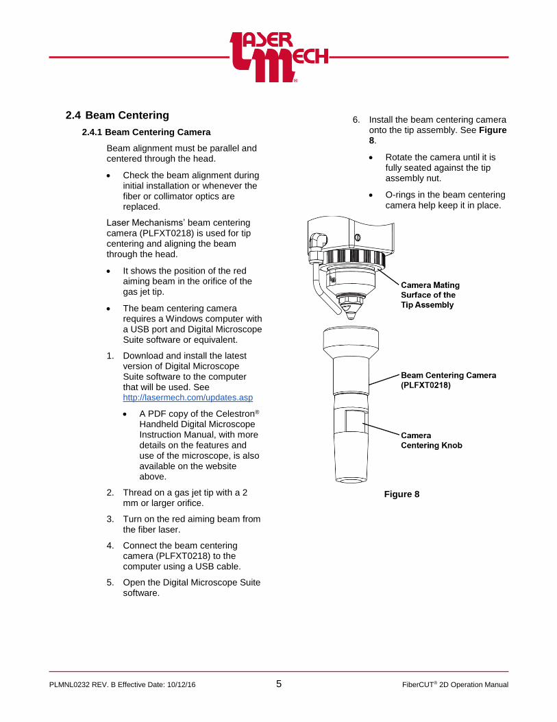
6. Install the beam centering camera onto the tip assembly. See Figure 8.
Rotate the camera until it is fully seated against the tip assembly nut.
O-rings in the beam centering camera help keep it in place.
Figure 8
PLMNL0232 REV. B Effective Date: 10/12/16 6 FiberCUT® 2D Operation Manual
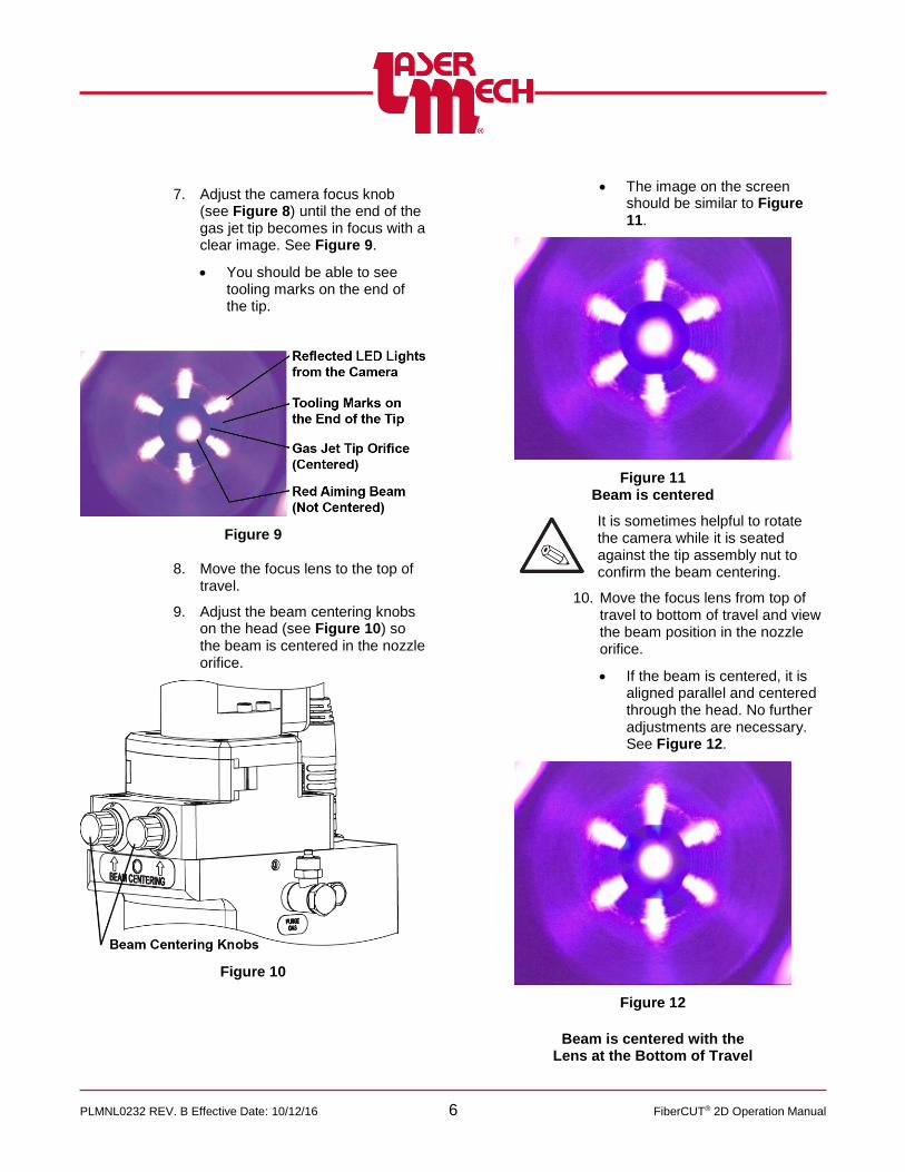
7. Adjust the camera focus knob (see Figure 8) until the end of the gas jet tip becomes in focus with a clear image. See Figure 9.
You should be able to see tooling marks on the end of the tip.
Figure 9
8. Move the focus lens to the top of travel.
9. Adjust the beam centering knobs on the head (see Figure 10) so the beam is centered in the nozzle orifice.
Figure 10
The image on the screen should be similar to Figure 11.
Figure 11 Beam is centered
It is sometimes helpful to rotate the camera while it is seated against the tip assembly nut to confirm the beam centering.
10. Move the focus lens from top of travel to bottom of travel and view the beam position in the nozzle orifice.
If the beam is centered, it is aligned parallel and centered through the head. No further adjustments are necessary. See Figure 12.
Figure 12
Beam is centered with the Lens at the Bottom of Travel

PLMNL0232 REV. B Effective Date: 10/12/16 7 FiberCUT® 2D Operation Manual
If the beam is not centered, continue to step 11. See Figure 13.
Figure 13
Beam is NOT centered with the Lens at the Bottom of Travel
For step 11 and 12, see Figure 14. 11. Use a 3mm hex wrench to loosen
the four M5 LHCS on the collimator approximately 1/4 turn.
These screws contain Belleville washers that apply some spring force.
12. Use a 3mm hex wrench to adjust the collimator XY set screws until the beam is centered in the nozzle orifice with the lens at bottom of travel.
There is only one X set screw that is spring loaded from the opposite side.
There are two opposing Y set screws.
Adjust the X set screw first. It may be necessary to loosen the Y set screws.
Adjust the Y set screws second.
Figure 14
13. Move the focus lens from bottom of travel to top of travel and view the beam position in the nozzle orifice.
If the beam is centered, tighten the four M5 LHCS on the collimator. No further adjustments are necessary.
If the beam is not centered, repeat steps 8 – 13 until the beam is centered.

PLMNL0232 REV. B Effective Date: 10/12/16 8 FiberCUT® 2D Operation Manual
2.4.2 Manually
Do not look directly into the red beam.
Visually locating the beam inside the tip orifice can be difficult. Adequate lighting and a magnifying glass are highly recommended.
If necessary, Laser Mechanisms offers an alternative solution. See Section 2.4.1, Beam Centering Camera.
To manually center the beam in the gas jet tip:
1. Verify that the high power beam is disabled.
2. Put a piece of translucent tape on the end of the gas jet tip.
3. Turn on the laser’s internal red pointing beam and observe the position of the beam on the tape. If the beam is not centered in the gas jet tip orifice, proceed to step 4.
4. Center the beam inside the gas jet tip orifice using the beam centering knobs. See Figure 15.
Some trial and error may be necessary.
Figure 15
PLMNL0232 REV. B Effective Date: 10/12/16 9 FiberCUT® 2D Operation Manual
3 Electrical Installation and Operation
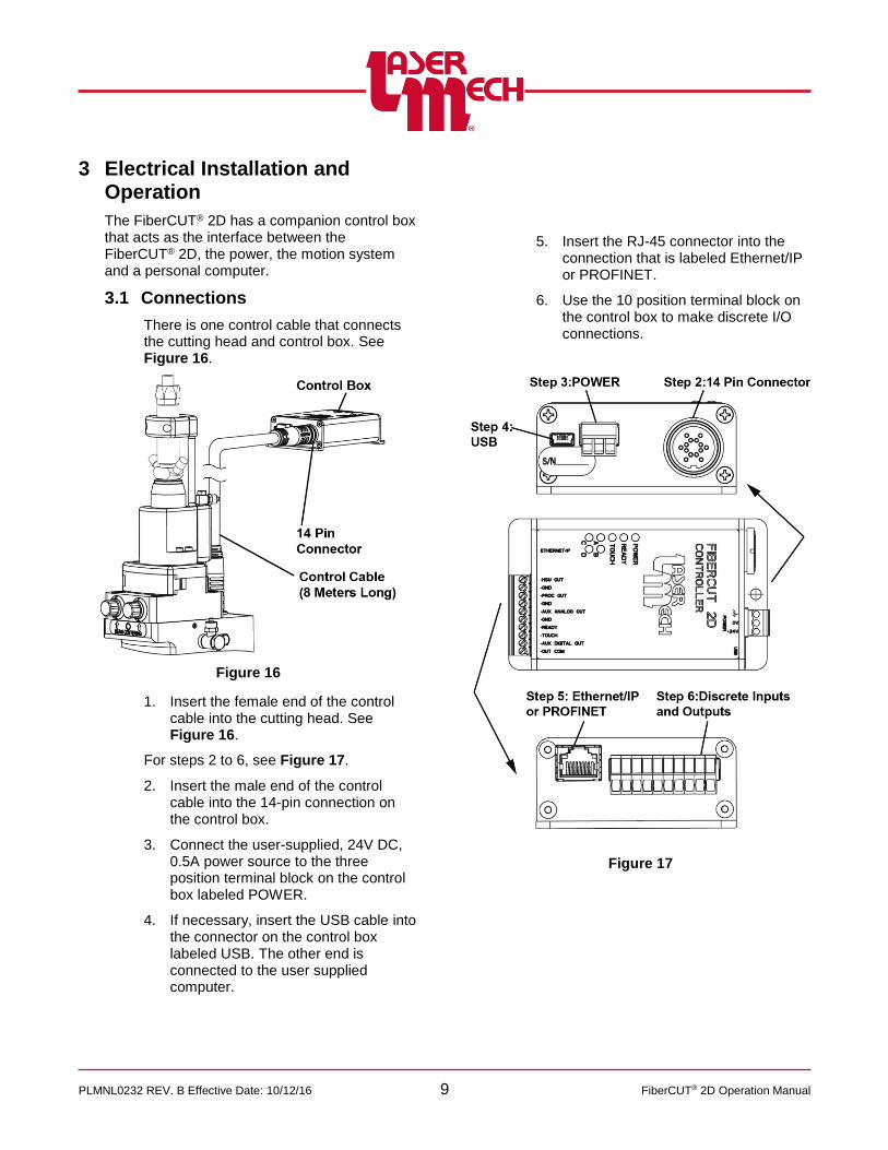
The FiberCUT® 2D has a companion control box that acts as the interface between the FiberCUT® 2D, the power, the motion system and a personal computer.
3.1 Connections
There is one control cable that connects the cutting head and control box. See Figure 16.
Figure 16
1. Insert the female end of the control cable into the cutting head. See Figure 16.
For steps 2 to 6, see Figure 17.
2. Insert the male end of the control cable into the 14-pin connection on the control box.
3. Connect the user-supplied, 24V DC, 0.5A power source to the three position terminal block on the control box labeled POWER.
4. If necessary, insert the USB cable into the connector on the control box labeled USB. The other end is connected to the user supplied computer.
5. Insert the RJ-45 connector into the connection that is labeled Ethernet/IP or PROFINET.
6. Use the 10 position terminal block on the control box to make discrete I/O connections.
Figure 17
PLMNL0232 REV. B Effective Date: 10/12/16 10 FiberCUT® 2D Operation Manual
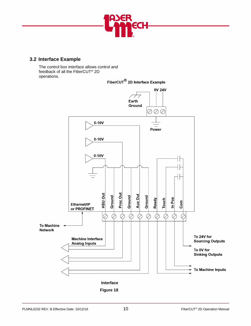
3.2 Interface Example
The control box interface allows control and feedback of all the FiberCUT® 2D operations.
Interface
Figure 18
PLMNL0232 REV. B Effective Date: 10/12/16 11 FiberCUT® 2D Operation Manual
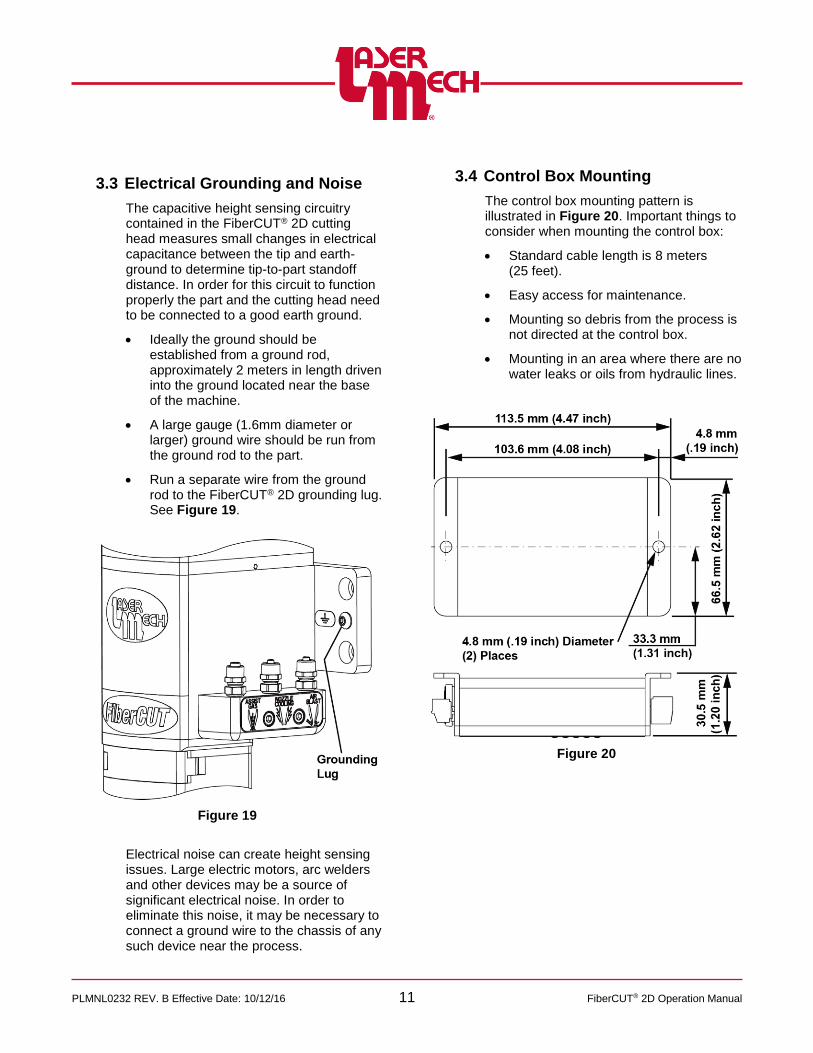
3.3 Electrical Grounding and Noise
The capacitive height sensing circuitry contained in the FiberCUT® 2D cutting head measures small changes in electrical capacitance between the tip and earth-ground to determine tip-to-part standoff distance. In order for this circuit to function properly the part and the cutting head need to be connected to a good earth ground.
Ideally the ground should be established from a ground rod, approximately 2 meters in length driven into the ground located near the base of the machine.
A large gauge (1.6mm diameter or larger) ground wire should be run from the ground rod to the part.
Run a separate wire from the ground rod to the FiberCUT® 2D grounding lug. See Figure 19.
Figure 19
Electrical noise can create height sensing issues. Large electric motors, arc welders and other devices may be a source of significant electrical noise. In order to eliminate this noise, it may be necessary to connect a ground wire to the chassis of any such device near the process.
3.4 Control Box Mounting
The control box mounting pattern is illustrated in Figure 20. Important things to consider when mounting the control box:
Standard cable length is 8 meters (25 feet).
Easy access for maintenance.
Mounting so debris from the process is not directed at the control box.
Mounting in an area where there are no water leaks or oils from hydraulic lines.
Figure 20
PLMNL0232 REV. B Effective Date: 10/12/16 12 FiberCUT® 2D Operation Manual
0
1
2
3
4
5
6
7
8
9
10
0 1 2 3 4 5 6 7 8 9 10 11 12 13 14 15 16 17 18 19 20
Vo
lts
Tip Standoff Distance (mm)
HSU Output
HSU out (Linear)
HSU out (Optimized)
3.5 Control Box Interface
3.5.1 Terminal Block Connections
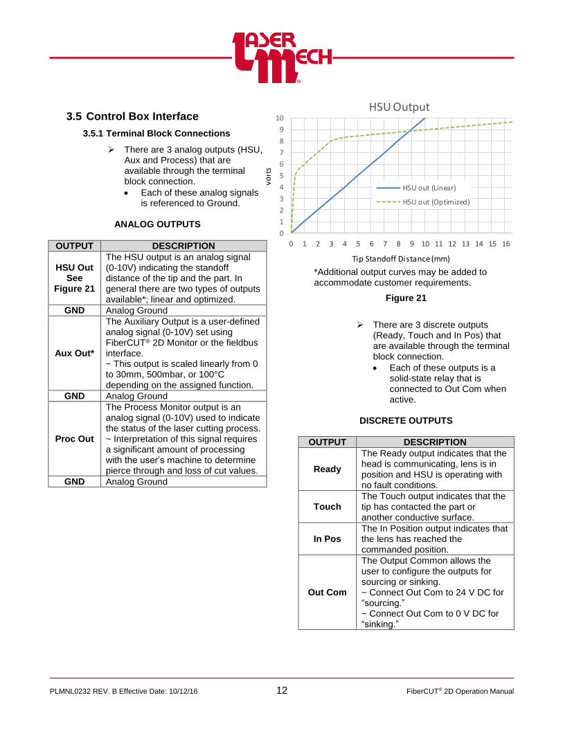
There are 3 analog outputs (HSU, Aux and Process) that are available through the terminal block connection.
Each of these analog signals is referenced to Ground.
ANALOG OUTPUTS
OUTPUT DESCRIPTION
HSU Out See
Figure 21
The HSU output is an analog signal (0-10V) indicating the standoff distance of the tip and the part. In general there are two types of outputs available*; linear and optimized.
GND Analog Ground
Aux Out*
The Auxiliary Output is a user-defined analog signal (0-10V) set using FiberCUT® 2D Monitor or the fieldbus interface. ~ This output is scaled linearly from 0 to 30mm, 500mbar, or 100°C depending on the assigned function.
GND Analog Ground
Proc Out
The Process Monitor output is an analog signal (0-10V) used to indicate the status of the laser cutting process. ~ Interpretation of this signal requires a significant amount of processing with the user’s machine to determine pierce through and loss of cut values.
GND Analog Ground
Figure 21
There are 3 discrete outputs (Ready, Touch and In Pos) that are available through the terminal block connection.
Each of these outputs is a solid-state relay that is connected to Out Com when active.
DISCRETE OUTPUTS
OUTPUT DESCRIPTION
Ready
The Ready output indicates that the head is communicating, lens is in position and HSU is operating with no fault conditions.
Touch The Touch output indicates that the tip has contacted the part or another conductive surface.
In Pos The In Position output indicates that the lens has reached the commanded position.
Out Com
The Output Common allows the user to configure the outputs for sourcing or sinking. ~ Connect Out Com to 24 V DC for “sourcing.” ~ Connect Out Com to 0 V DC for “sinking.”
*Additional output curves may be added to accommodate customer requirements.

PLMNL0232 REV. B Effective Date: 10/12/16 13 FiberCUT® 2D Operation Manual
3.5.2 Fieldbus Connection
The Fieldbus interface provides extensive control and monitoring of the FiberCUT® 2D. Depending on the control box model, either EtherNet/IP or PROFINET communications protocol is used.
See Appendix E for details on device configuration and available data.
3.6 Control Box Indicator Lights
The control box has 7 indicator lights. See Figure 22.
The indicator light labeled POWER is green and illuminated when power is supplied to the control box.
The indicator light labeled READY is
illuminated in green when the READY
output is active. The light illuminates in red when a fault is detected within the head.
The indicator light labeled TOUCH is green and illuminated when the tip is in contact with the part or another conductive surface.
The indicator lights labeled A, B, C, and D may be red or green. They work together to indicate the network status of the Fieldbus connection and other diagnostic information. See the charts below.
At power up or reset, the four indicators will cycle in the order A>B>D>C first in red and then in green. This pattern confirms the Fieldbus module is installed and functioning properly.
Figure 22

PLMNL0232 REV. B Effective Date: 10/12/16 14 FiberCUT® 2D Operation Manual
During normal operation the indicator lights respond as follows:
LED A
STATE STATUS
Green Module connected to a network
Green and Flashing
RX / TX Activity
Red Control box operation suspended, initializing USB connection
LED B
STATE STATUS
Green Ethernet/IP: 100 Mbps operation
Green and Flashing
PROFINET: Identification
Red No communications with head
Red and Flashing
PROFINET: Diagnostic event(s) available
LED C
STATE STATUS
Green EtherNet/IP: Device has a connection PROFINET: Normal operation
Green and Flashing
EtherNet/IP: Device has no connection PROFINET: Network settings error
Red EtherNet/IP: Major fault (unrecoverable) PROFINET: Internal error
Red and Flashing
EtherNet/IP: Minor fault (recoverable) PROFINET: Configuration error
LED D
STATE STATUS
Green EtherNet/IP: connection(s) established PROFINET: Online, PLC in RUN
Green and Flashing
EtherNet/IP: No connection established PROFINET: Online, PLC in STOP/CLEAR
Red EtherNet/IP: Duplicate IP address detected PROFINET: Internal error
Red and Flashing
EtherNet/IP: One (or multiple) connections has timed out

PLMNL0232 REV. B Effective Date: 10/12/16 15 FiberCUT® 2D Operation Manual
1.
4 FiberCUT® 2D Monitor
FiberCUT® 2D Monitor is a very useful tool for use with your FiberCUT® 2D head. FiberCUT® 2D Monitor runs on a standard PC and connects to the control box with a USB cable. It provides real time monitoring of the tip standoff, lens position, and head temperatures of your FiberCUT® 2D on a single, easy-to-read screen. See Figure 23.
Figure 23
4.1 Installation
4.1.1 Downloading FiberCUT® 2D Monitor Software
Download the latest copy of FiberCUT® 2D Monitor from the FiberCUT® Updates web page:
http://www.lasermech.com/fibercut2dupdates.asp
Once the compressed folder is downloaded from the web site it only needs to be decompressed.
1. Right-click on the compressed folder and select Extract All....
2. Follow the on-screen instructions to complete the decompression (extraction) of the compressed files.
The resulting folder will have a single FiberCutMonitor2D.exe file, a driver folder, and a folder named FiberCutMonitor2D Libs.
It is important that the Libs folder remain at the same location as FiberCUT® 2D Monitor.
The parent folder for these files can be moved and copied as needed. No license key is needed.

PLMNL0232 REV. B Effective Date: 10/12/16 16 FiberCUT® 2D Operation Manual
4.1.2 Installing FiberCUT® 2D Monitor Driver
Before operating the FiberCUT® 2D Monitor, it must be connected to a customer supplied Windows based computer. If the system is connected and is not recognized, light A will remain illuminated in red on the control box (see Figure 22). In this case, install the driver (Freescale Virtual Com Port, located in the same folder as the software) using the following:
Administrator rights to your computer are required to complete the driver installation.
1. Navigate to the device manager.
The display is a list of all the devices installed.
2. Right-click on “FIBERCUT 2D I/O” and select “Update Driver Software…”
3. Click on “Browse my computer for driver software”.
4. Click on the “Browse” button.
5. Locate and open the folder containing the FiberCUT® 2D Monitor software, click on the “Driver” folder, and then click “OK”.
6. Click on the “Next” button.
7. A security message may appear warning that Windows can’t verify the publisher of this driver software.
8. If this happens, click on “Install this driver software anyway”.
9. The driver should now install. Once it has completed, click “Close”.
10. Look under the “Ports (COM & LPT)” category in the device list.
You should now see “Virtual Com Port” followed by a COM number in parenthesis.
Make note of this number. It is the port you will need to select to use the FiberCUT® 2D Monitor software.
4.2 System Requirements
Windows 7 or later
Minimum Screen Resolution: 1024 x 768
USB 1.1 Port
4.3 Using FiberCUT® 2D Monitor
4.3.1 Start Up
1. Verify that all cables are connected to the head and control box according to Section 3.1.
The screen shown in Figure 24 will appear.
Figure 24

PLMNL0232 REV. B Effective Date: 10/12/16 17 FiberCUT® 2D Operation Manual
For steps 2 and 3, see Figure 25.
2. Click on the Port drop down menu in the upper left corner and choose the appropriate port.
3. Click Connect.
Figure 25
The Main screen appears. See Figure 26 for an example.
4. Update any settings, as necessary, according to Section 4.4.
4.3.2 System Controls
See Figure 26 (the Main screen).
Figure 26
1. Click the following, as necessary:
Click the Reset button to move the lens to the zero position and clear a Lens Fault.
To modify the Set Position
o Use the slider bar on the right to update the Set Position value.
o Click the Go button to apply the new value.
Click the Calibrate button to recalibrate the HSU.
Perform calibration at 12 mm above the material surface.
o Use the Calibrate button to clear a Tip or Cable Break fault.
o An alternate method to recalibrate the FiberCUT® 2D Monitor is to click the Settings menu in the upper left corner of the Main screen and select Calibrate. See Figure 27.
Figure 27

PLMNL0232 REV. B Effective Date: 10/12/16 18 FiberCUT® 2D Operation Manual
Click the Disconnect button (top center of the Main Screen) or the red X (upper right corner of the Main screen) to disconnect the control box and head.
o Either of these actions will end the session.
2. Note the following displays:
The status of the head is displayed in the upper right corner of the Main Screen.
If the tip contacts another surface, the indicator light next to TIP TOUCH (lower right of the Main screen) will be illuminated green.
The Main screen displays the current value of:
o Standoff Height
o Focus Position
o Temperature for electronics, both cover glasses, process monitor, focusing lens, and nozzle
o Purge gas pressure
4.3.3 Faults and Status Indicator
See Figure 26 (the Main screen).
When a fault occurs, the Ready output turns off and the corresponding light on the control box turns red. A description of the fault is also displayed in red in the upper right corner of the Main screen and the module responsible for the fault will be highlighted on the diagram of the head.
Faults occur when:
The HSU fails to calibrate.
A cable break occurs within the head. For instance, if the tip assembly is removed.
Communication between the controller and head is lost.
A temperature goes above the upper limit.
A cover glass door is open or drawer is removed.
The purge pressure goes below the lower limit (unless suppressed) or above the upper limit.
The lens travels outside its allowed range or takes too long to reach the commanded position.
The status indicator may also show that the head is Not Ready if the head is operating normally but is not ready for laser processing, such as when the HSU is calibrating.
The on-screen Ready indicator may not change during some operations due to the software refresh interval. See the READY output or light on the control box for real-time status.
PLMNL0232 REV. B Effective Date: 10/12/16 19 FiberCUT® 2D Operation Manual
4.4 FiberCUT® 2D Monitor Settings
The FiberCUT® 2D software and driver are available for download. See Section 4.1 for details.
This section lists the settings that must be specified before operating FiberCUT® 2D Monitor.
Before adjusting any settings:
The software must be installed on your PC. See Section 4.1 for more details.
The head and control box must be connected properly. See Section 3.1 for more details.
4.4.1 Unlock Settings
1. Click the Settings menu in the upper left corner of the Main screen and select Unlock Settings. See Figure 28.
In the pop up that appears, enter the password: cutsetup.
Figure 28
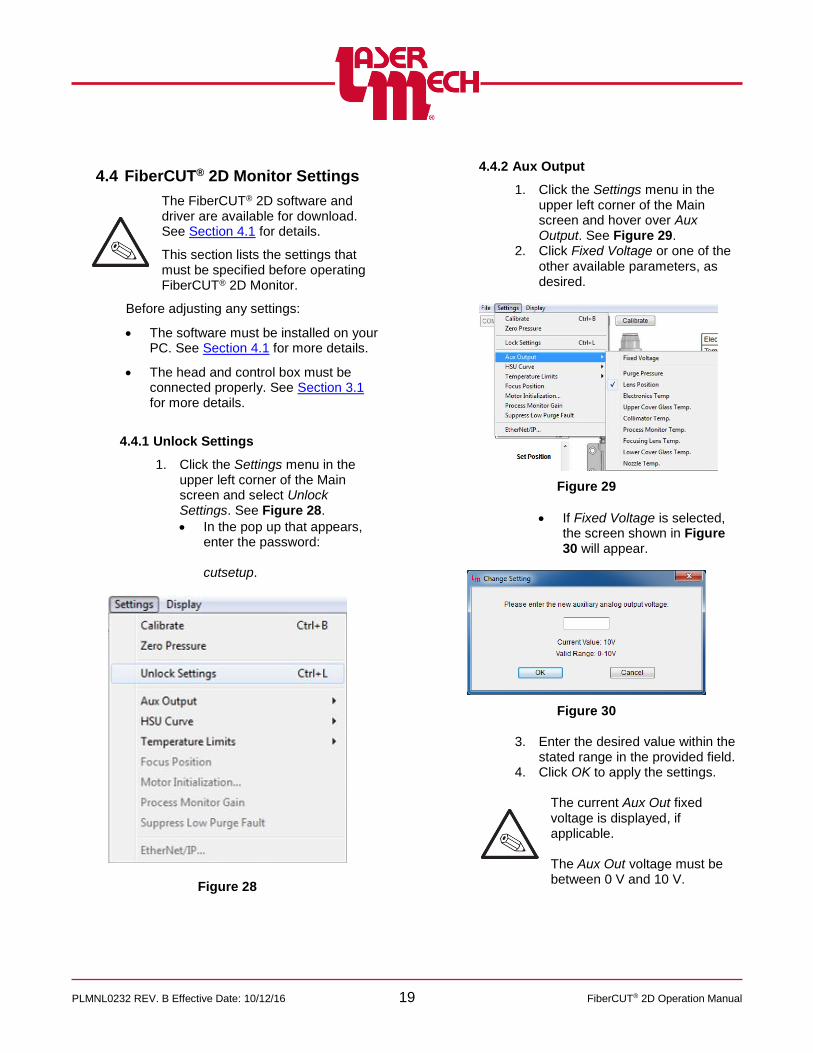
4.4.2 Aux Output
1. Click the Settings menu in the upper left corner of the Main screen and hover over Aux Output. See Figure 29.
2. Click Fixed Voltage or one of the other available parameters, as desired.
Figure 29
If Fixed Voltage is selected, the screen shown in Figure 30 will appear.
Figure 30
3. Enter the desired value within the stated range in the provided field.
4. Click OK to apply the settings.
The current Aux Out fixed voltage is displayed, if applicable.
The Aux Out voltage must be between 0 V and 10 V.
PLMNL0232 REV. B Effective Date: 10/12/16 20 FiberCUT® 2D Operation Manual
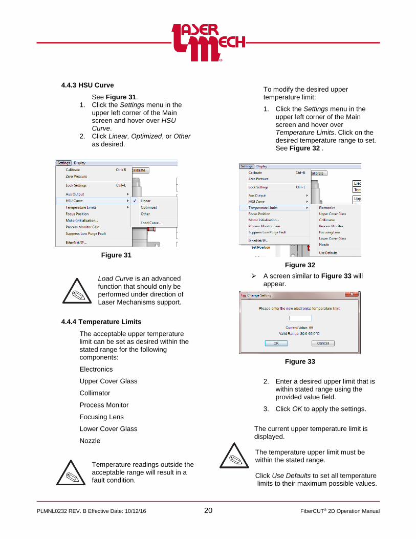
4.4.3 HSU Curve
See Figure 31. 1. Click the Settings menu in the
upper left corner of the Main screen and hover over HSU Curve.
2. Click Linear, Optimized, or Other as desired.
Figure 31
Load Curve is an advanced function that should only be performed under direction of Laser Mechanisms support.
4.4.4 Temperature Limits
The acceptable upper temperature limit can be set as desired within the stated range for the following components:
Electronics
Upper Cover Glass
Collimator
Process Monitor
Focusing Lens
Lower Cover Glass
Nozzle
Temperature readings outside the acceptable range will result in a fault condition.
To modify the desired upper temperature limit:
1. Click the Settings menu in the upper left corner of the Main screen and hover over Temperature Limits. Click on the desired temperature range to set. See Figure 32 .
Figure 32
A screen similar to Figure 33 will appear.
Figure 33
2. Enter a desired upper limit that is within stated range using the provided value field.
3. Click OK to apply the settings.
The current upper temperature limit is displayed. The temperature upper limit must be within the stated range. Click Use Defaults to set all temperature limits to their maximum possible values.
PLMNL0232 REV. B Effective Date: 10/12/16 21 FiberCUT® 2D Operation Manual
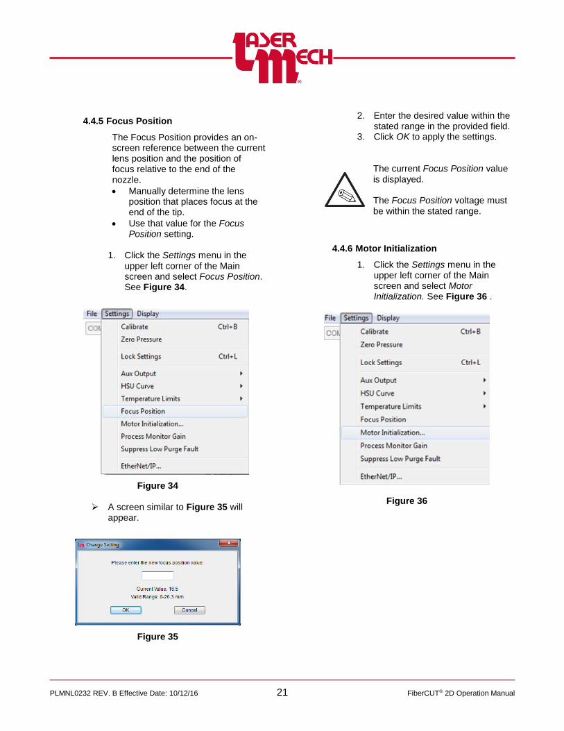
4.4.5 Focus Position
The Focus Position provides an on-screen reference between the current lens position and the position of focus relative to the end of the nozzle.
Manually determine the lens position that places focus at the end of the tip.
Use that value for the Focus Position setting.
1. Click the Settings menu in the
upper left corner of the Main screen and select Focus Position. See Figure 34.
Figure 34
A screen similar to Figure 35 will appear.
Figure 35
2. Enter the desired value within the
stated range in the provided field. 3. Click OK to apply the settings.
The current Focus Position value is displayed.
The Focus Position voltage must be within the stated range.
4.4.6 Motor Initialization
1. Click the Settings menu in the upper left corner of the Main screen and select Motor Initialization. See Figure 36 .
Figure 36

PLMNL0232 REV. B Effective Date: 10/12/16 22 FiberCUT® 2D Operation Manual
For steps 2 to 5, see Figure 37 .
The Motor Initialization screen, shown in Figure 37, will appear.
Figure 37
The values shown may not reflect the current motor values. They only are used to program the motor. 2. Click on a value to display a
settings box for that parameter. 3. Once all values are set as
desired, click Initialize Motor to store settings into motor. To return to the factory settings:
4. Click Set To Default Values to reset all values to factory settings.
5. Click Initialize Motor to store settings into motor.
4.4.7 Process Monitor Gain
The process monitor output can be adjusted to compensate for signal differences in the cutting process by using the gain setting.
1. Click the Settings menu in the
upper left corner of the Main screen and select Process Monitor Gain. See Figure 38.
Figure 38
A screen similar to Figure 39 will appear.
Figure 39
PLMNL0232 REV. B Effective Date: 10/12/16 23 FiberCUT® 2D Operation Manual
2. Enter the desired value within the
stated range in the provided field. 3. Click OK to apply the settings.
The current Process Gain Monitor value is displayed.
Typical Process Monitor Gain values are in the lower half of the allowed range.
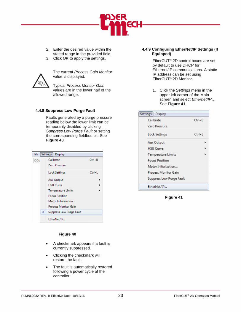
4.4.8 Suppress Low Purge Fault
Faults generated by a purge pressure reading below the lower limit can be temporarily disabled by clicking Suppress Low Purge Fault or setting the corresponding fieldbus bit. See Figure 40.
Figure 40
A checkmark appears if a fault is currently suppressed.
Clicking the checkmark will restore the fault.
The fault is automatically restored following a power cycle of the controller.
4.4.9 Configuring EtherNet/IP Settings (If
Equipped)
FiberCUT® 2D control boxes are set by default to use DHCP for Ethernet/IP communications. A static IP address can be set using FiberCUT® 2D Monitor.
1. Click the Settings menu in the
upper left corner of the Main screen and select Ethernet/IP… See Figure 41.
Figure 41

PLMNL0232 REV. B Effective Date: 10/12/16 24 FiberCUT® 2D Operation Manual
For steps 2 to 6, see Figure 42. 2. Click the Settings menu in the
upper left corner of the Main screen and select Ethernet/IP…
The Ethernet/IP Settings screen, shown in Figure 42, will appear.
Figure 42
3. Configure the DHCP, IP Address, Subnet Mask, and Gateway settings as desired.
When using EtherNet/IP, Swap Byte Order should be checked.
4. Click OK to apply the settings. 5. If desired, click the Store button to
save the changes to the control box.
6. If desired, click the Reset button to reset the control box and implement the new configuration.
Otherwise, power must be cycled in order for new settings to take effect.
4.5 FiberCUT® 2D Monitor System Identification Information
The hardware, controller, interface, and HSU are all specific to your system. So, version and serial numbers are critical in order for Laser Mechanisms to provide support.
To display system information:
1. Click the Display menu in the upper left corner of the Main screen and select About FiberCUT® 2D… See Figure 43.
Figure 43
2. Click on the View Hardware Information drop down menu in the pop up box that appears and the image shown in Figure 44 will appear.
Figure 44
3. Click on the appropriate line to view the identifying information for the desired item.
4. Repeat steps 2 and 3 as needed. 5. Click OK to exit the About FiberCUT®
2D screen.

PLMNL0232 REV. B Effective Date: 10/12/16 25 FiberCUT® 2D Operation Manual
5 Service
Routine maintenance and service is required for the FiberCUT® 2D Head. The operating environment has a critical impact on the frequency of maintenance procedures. Consult your Laser Mechanisms representative for guidance.
5.1 Servicing the Gas Jet Tip
To remove the gas jet tip:
1. Unscrew the tip retainer nut assembly from the tip assembly. See Figure 45.
2. Unscrew the inner retainer from the outer hex and remove the gas jet tip. See Figure 46.
Figure 45
Figure 46
To replace the gas jet nozzle tip:
For steps 3 and 4, see Figure 46.
3. Insert the gas jet tip into the inner retainer.
4. Screw the inner retainer into the outer hex. Do not over tighten.
Hand tighten the tip retainer nut assembly. Do not use a wrench.
5. Screw the tip retainer nut assembly with gas jet tip into the tip assembly. Do not over tighten. See Figure 45.
Hand tighten the tip retainer nut assembly. Do not use a wrench.
6. Verify beam centering according to Section 2.4.
PLMNL0232 REV. B Effective Date: 10/12/16 26 FiberCUT® 2D Operation Manual
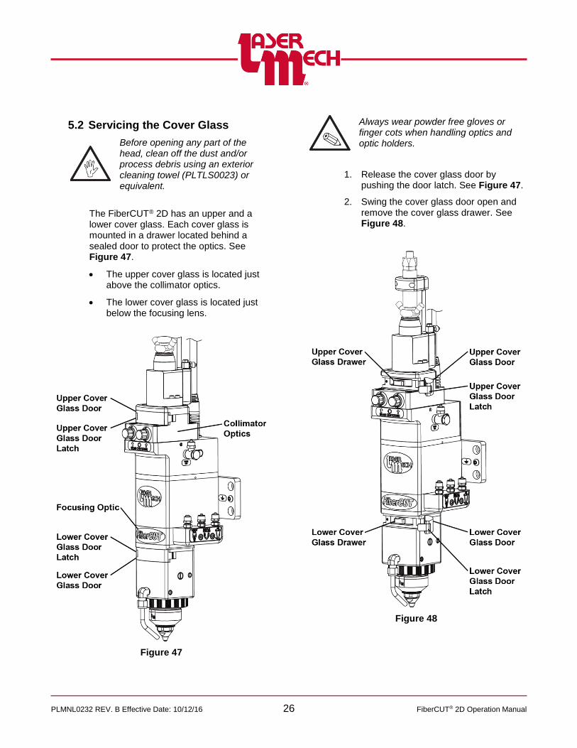
5.2 Servicing the Cover Glass
Before opening any part of the head, clean off the dust and/or process debris using an exterior cleaning towel (PLTLS0023) or equivalent.
The FiberCUT® 2D has an upper and a lower cover glass. Each cover glass is mounted in a drawer located behind a sealed door to protect the optics. See Figure 47.
The upper cover glass is located just above the collimator optics.
The lower cover glass is located just below the focusing lens.
Figure 47
Always wear powder free gloves or finger cots when handling optics and optic holders.
1. Release the cover glass door by pushing the door latch. See Figure 47.
2. Swing the cover glass door open and remove the cover glass drawer. See Figure 48.
Figure 48
PLMNL0232 REV. B Effective Date: 10/12/16 27 FiberCUT® 2D Operation Manual
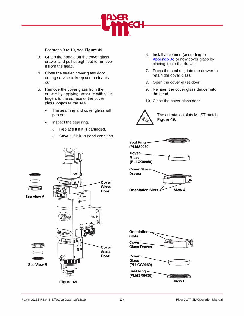
For steps 3 to 10, see Figure 49.
3. Grasp the handle on the cover glass drawer and pull straight out to remove it from the head.
4. Close the sealed cover glass door during service to keep contaminants out.
5. Remove the cover glass from the drawer by applying pressure with your fingers to the surface of the cover glass, opposite the seal.
The seal ring and cover glass will pop out.
Inspect the seal ring.
o Replace it if it is damaged.
o Save it if it is in good condition.
Figure 49
6. Install a cleaned (according to Appendix A) or new cover glass by placing it into the drawer.
7. Press the seal ring into the drawer to retain the cover glass.
8. Open the cover glass door.
9. Reinsert the cover glass drawer into the head.
10. Close the cover glass door.
The orientation slots MUST match Figure 49.
PLMNL0232 REV. B Effective Date: 10/12/16 28 FiberCUT® 2D Operation Manual
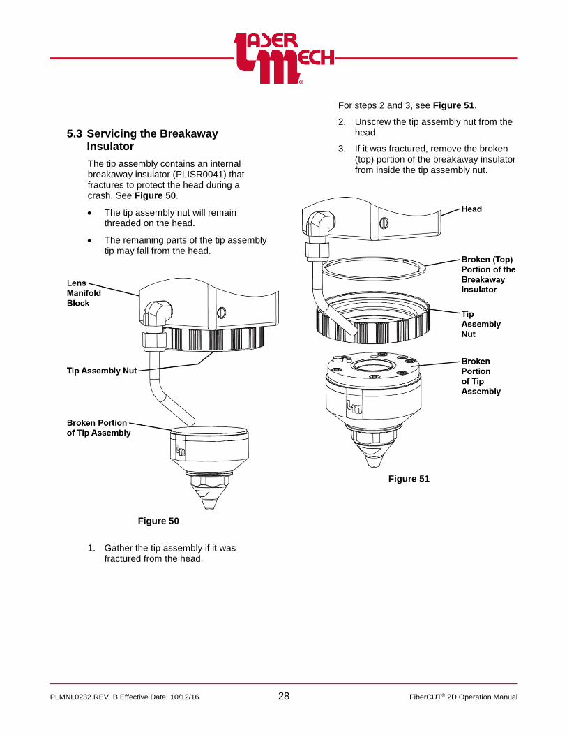
5.3 Servicing the Breakaway Insulator
The tip assembly contains an internal breakaway insulator (PLISR0041) that fractures to protect the head during a crash. See Figure 50.
The tip assembly nut will remain threaded on the head.
The remaining parts of the tip assembly tip may fall from the head.
Figure 50
1. Gather the tip assembly if it was fractured from the head.
For steps 2 and 3, see Figure 51.
2. Unscrew the tip assembly nut from the head.
3. If it was fractured, remove the broken (top) portion of the breakaway insulator from inside the tip assembly nut.
Figure 51
PLMNL0232 REV. B Effective Date: 10/12/16 29 FiberCUT® 2D Operation Manual
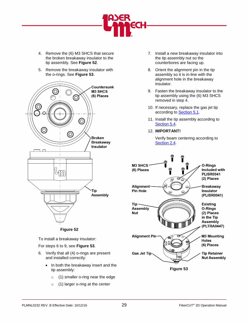
4. Remove the (6) M3 SHCS that secure the broken breakaway insulator to the tip assembly. See Figure 52.
5. Remove the breakaway insulator with the o-rings. See Figure 53.
Figure 52
To install a breakaway insulator:
For steps 6 to 9, see Figure 53.
6. Verify that all (4) o-rings are present and installed correctly:
In both the breakaway insert and the tip assembly:
o (1) smaller o-ring near the edge
o (1) larger o-ring at the center
7. Install a new breakaway insulator into the tip assembly nut so the counterbores are facing up.
8. Orient the alignment pin in the tip assembly so it is in-line with the alignment hole in the breakaway insulator.
9. Fasten the breakaway insulator to the tip assembly using the (6) M3 SHCS removed in step 4.
10. If necessary, replace the gas jet tip according to Section 5.1.
11. Install the tip assembly according to Section 5.4.
12. IMPORTANT!
Verify beam centering according to Section 2.4.
Figure 53

PLMNL0232 REV. B Effective Date: 10/12/16 30 FiberCUT® 2D Operation Manual
5.4 Servicing the Tip Assembly
See Figure 54.
To remove:
1. Unthread the tip assembly nut and remove the tip assembly from the head.
Figure 54
To install:
2. Verify that the alignment flat on the tip assembly faces the front of the head and the air blast.
3. Push the tip retainer assembly up until it is centered on and flush against the head.
4. Rotate the tip retainer assembly slightly until the alignment pin seats in the alignment hole in the head.
5. Thread the retainer nut into the head.
Do not allow the aligned components to rotate.
5.5 Removing the Fiber
EVERY TIME the fiber is removed and/or installed the upper cover glass MUST BE inspected.
Before opening any part of the head, clean off the dust and/or process debris using an exterior cleaning towel (PLTLS0023) or equivalent.
1. Wipe the head clean of any foreign matter prior to removing the head.
2. Verify that the upper cover glass is in place.
3. Remove the fiber clamp according to Section 2.3.1.
4. Remove the fiber optic cable from the cutting head.
5. Cover the fiber end with an appropriate cap from the fiber manufacturer.
Special attention must be given to the fiber optic cable.
Care must be taken to insure dirt and debris do not contaminate the glass block at the end of the fiber.
Plug or tape off the fiber input to prevent contamination.
Damage will occur if:
The output is not covered with manufacturer’s cap.
The fiber input adapter is not protected by the provided dust cover.

PLMNL0232 REV. B Effective Date: 10/12/16 31 FiberCUT® 2D Operation Manual
5.6 Servicing the Focus Lens
Before opening any part of the head, clean off the dust and/or process debris using an exterior cleaning towel (PLTLS0023) or equivalent.
To change the focus lens, the tip assembly and manifold block must be removed and relocated to a clean dry area. Individual optics may be cleaned (according to Appendix A) or replaced.
1. Move the focus lens to the bottom of travel.
2. Remove the tip assembly according to Section 5.4.
The manifold block must be removed to service the focusing optics.
For steps 3 to 5, see Figure 55.
3. Loosen the (3) captive M5 x 80 SHCS that secure the manifold block to the head.
4. Remove the manifold block.
5. Verify that all (4) o-rings are present in the manifold block and installed correctly.
The o-rings should NOT be stuck on the head.
Figure 55

PLMNL0232 REV. B Effective Date: 10/12/16 32 FiberCUT® 2D Operation Manual
6. Use the lens insertion tool (PLLIT0034) to unthread the focus lens cartridge from the head. See Figure 56.
If necessary, cover the bottom of the head with tape to prevent contamination.
Figure 56
It is strongly recommended to replace the entire focus lens cartridge (PLFLH0381) so the lens is less likely to become contaminated from direct handling.
If the lens must be removed from the cartridge, see the following steps.
For steps 7 and 8, see Figure 57.
7. Using the opposite end of PLLIT0034, unthread the lens retainer nut.
ALWAYS wear powder free gloves or finger cots when handling optics and optic holders.
Inspect the optics with high power illumination, such as Laser Mechanisms pen light (part number PLTLS0021) under 2X magnification.
8. Carefully remove the components, noting the orientation of the seal ring, lens and lens back up ring.
Figure 57
PLMNL0232 REV. B Effective Date: 10/12/16 33 FiberCUT® 2D Operation Manual
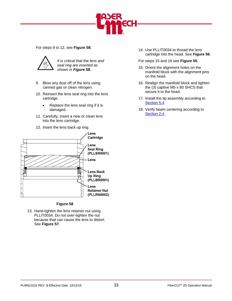
For steps 9 to 12, see Figure 58.
It is critical that the lens and seal ring are inserted as shown in Figure 58.
9. Blow any dust off of the lens using canned gas or clean nitrogen.
10. Reinsert the lens seal ring into the lens cartridge.
Replace the lens seal ring if it is damaged.
11. Carefully, insert a new or clean lens into the lens cartridge.
12. Insert the lens back up ring.
Figure 58
13. Hand-tighten the lens retainer nut using PLLIT0034. Do not over-tighten the nut because that can cause the lens to distort. See Figure 57.
14. Use PLLIT0034 to thread the lens cartridge into the head. See Figure 56.
For steps 15 and 16 see Figure 55.
15. Orient the alignment holes on the manifold block with the alignment pins on the head.
16. Realign the manifold block and tighten the (3) captive M5 x 80 SHCS that secure it to the head.
17. Install the tip assembly according to Section 5.4.
18. Verify beam centering according to Section 2.4.
PLMNL0232 REV. B Effective Date: 10/12/16 34 FiberCUT® 2D Operation Manual
5.7 Adjusting the Focus Lens Position Manually
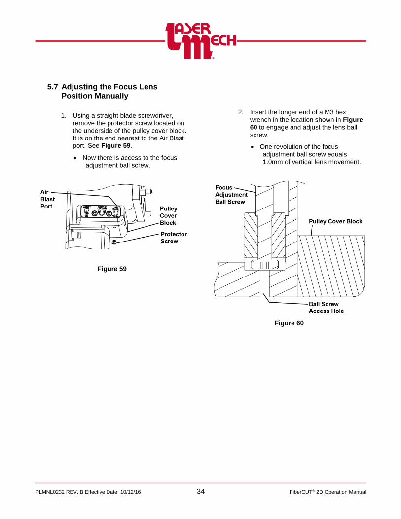
1. Using a straight blade screwdriver,
remove the protector screw located on the underside of the pulley cover block. It is on the end nearest to the Air Blast port. See Figure 59.
Now there is access to the focus adjustment ball screw.
Figure 59
2. Insert the longer end of a M3 hex wrench in the location shown in Figure 60 to engage and adjust the lens ball screw.
One revolution of the focus adjustment ball screw equals 1.0mm of vertical lens movement.
Figure 60
PLMNL0232 REV. B Effective Date: 10/12/16 35 FiberCUT® 2D Operation Manual
5.8 Servicing the Collimator Lens Cartridge
Before opening any part of the head, clean off the dust and/or process debris using an exterior cleaning towel (PLTLS0023) or equivalent.
The recommended procedure is to change the entire collimating lens cartridge; the fiber collimator must be removed from the cutting head.
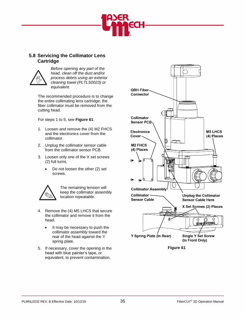
For steps 1 to 5, see Figure 61.
1. Loosen and remove the (4) M2 FHCS and the electronics cover from the collimator.
2. Unplug the collimator sensor cable from the collimator sensor PCB.
3. Loosen only one of the X set screws (2) full turns.
Do not loosen the other (2) set screws.
The remaining tension will keep the collimator assembly location repeatable.
4. Remove the (4) M5 LHCS that secure the collimator and remove it from the head.
It may be necessary to push the collimator assembly toward the rear of the head against the Y spring plate.
5. If necessary, cover the opening in the head with blue painter’s tape, or equivalent, to prevent contamination.
Figure 61
PLMNL0232 REV. B Effective Date: 10/12/16 36 FiberCUT® 2D Operation Manual
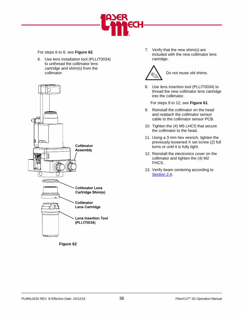
For steps 6 to 8, see Figure 62.
6. Use lens installation tool (PLLIT0034) to unthread the collimator lens cartridge and shim(s) from the collimator.
Figure 62
7. Verify that the new shim(s) are
included with the new collimator lens cartridge.
Do not reuse old shims.
8. Use lens insertion tool (PLLIT0034) to thread the new collimator lens cartridge into the collimator.
For steps 9 to 12, see Figure 61.
9. Reinstall the collimator on the head and reattach the collimator sensor cable to the collimator sensor PCB.
10. Tighten the (4) M5 LHCS that secure the collimator to the head.
11. Using a 3 mm hex wrench, tighten the previously loosened X set screw (2) full turns or until it is fully tight.
12. Reinstall the electronics cover on the collimator and tighten the (4) M2 FHCS.
13. Verify beam centering according to Section 2.4.

PLMNL0232 REV. B Effective Date: 10/12/16 37 FiberCUT® 2D Operation Manual
5.9 Removing the Cutting Head
Before opening any part of the head, clean off the dust and/or process debris using an exterior cleaning towel (PLTLS0023) or equivalent.
1. Remove the fiber according to Section 5.5.
2. The open area of the QBH receiver MUST be covered.
Use the manufacturer supplied dust cap.
OR
Use blue painter’s tape or equivalent.
For steps 3 and 4, see Figure 3 and Figure 4 in Section 2.2.
3. Turn off the water supply and disconnect the water fittings.
4. Remove the purge air, assist gas, air blast and nozzle cooling lines.
5. Disconnect the communication cable. See Figure 16 and Figure 17 in Section 3.1.
6. Unbolt the head from the machine using a 6mm hex wrench as shown in Figure 63.
Figure 63
7. Separate the head from the machine.
8. Take the cutting head to a clean area.

PLMNL0232 REV. B Effective Date: 10/12/16 38 FiberCUT® 2D Operation Manual
6 Specifications
CUTTING HEAD
Power Rating .............................................................................................................................. up to 6 kW
Focusing Lens (Nominal Focal Length) ............................................ 125 mm, 150 mm, 200 mm, 250 mm
Focusing Lens (Diameter) .............................................................................................................. 38.1 mm
Clear Aperture ................................................................................................................................... 35 mm
Nozzle Tip .............................................................................................. Various Shapes and Orifice Sizes
Assist Gas Pressure .................................................................................................. up to 25 Bar (375 psi)
Purge Gas ........................................................................................................ 0.2 – 0.3 Bar (3.0 – 5.0 psi)
Water ................................................................................................................ 5.0 Bar Max (72.5 psi max)
Weight ................................................................................................................................ 6.6 kg (14.5 lbs)
Focal Point to Nozzle Adjustment ................................................................................. -14 mm to +11 mm
COLLIMATOR
Nominal Focal Length (Doublet, Fused Silica) ...................................... 60 mm, 75 mm, 100 mm, 120 mm
Recollimating Lens (Diameter) .................................................... 28 mm (Standard) or 38 mm (120 Recol)
Clear Aperture .............................................................................. 25 mm (Standard) or 35 mm (120 Recol)
Fiber Socket (Others Available On Request) ......................................................................... QBH (HLC-8)
HEIGHT SENSOR
Standoff Distance Range ................................................................................................ 0.2 mm to 8.0 mm
Single Point Calibration ..................................................................................................................... 12 mm
Response Time .............................................................................................................................. <1 msec
Temperature Stability ......................................................................... ±5% of Standoff Setting, 0° to 45° C
Output ..................................................................................................................................... 0-10 V Analog
Specifications are subject to change without notice.

PLMNL0232 REV. B Effective Date: 10/12/16 39 FiberCUT® 2D Operation Manual
7 Troubleshooting
SYMPTOM CAUSE REMEDY
HSU Fault: 1: Tip Open
There is no connection between the HSU and tip assembly during calibration.
Verify that the tip assembly and internal sense cables are properly installed and then recalibrate.
HSU Fault: 2: Tip Shorted
The tip is not fully insulated from ground and the body of the cutting head during calibration.
Remove any debris that may be causing a short and then recalibrate.
HSU Fault: 3: Cable Break
The connection between the HSU and tip has been broken.
Verify that the tip assembly and tip are properly installed and then recalibrate.
HSU Fault: 5: Curve Data Error
There is no curve data in the selected location or the data failed to load correctly.
Load the curve data again or select a different curve number.
HSU Fault: 6: Invalid curve
number
The value in the Set HSU Curve fieldbus register is outside the allowed range (1-31).
Enter a valid number or 0 to idle the input.
HSU Fault: 7: Failed to set
curve
The HSU did not respond successfully to a value change in the Set HSU Curve fieldbus register.
Attempt to set the curve again by setting the value to 0 and then to the new curve number.
Verify the head and HSU are properly connected.
Lens Fault
The lens was out of the commanded position for an excessive amount of time.
Activate the Reset bit or button to re-establish the zero position of the motor.
The motor may have stalled or lost its zero position.
Verify that the motor is connected and properly initialized.
Purge Fault The purge pressure is too low or too high.
Verify that the purge gas is turned on and properly regulated.
Expand the allowable range by lowering or raising limits.
Temperature Fault
The temperature of one or more sensors has exceeded the limit.
Allow the component to cool. Consider raising the temperature limit if it is safe.
A cover glass drawer has been removed. Verify the drawers are fully inserted and the doors are latched securely.
A temperature sensor is disconnected. Check the internal cable connections.
Position Error
The Move Lens command could not be completed because the value in the Set Position fieldbus register is above the Maximum Position or a Lens Fault exists.
Clear the Move Lens bit. Activate the Reset bit if necessary. Enter a value that is less than or equal to the Maximum Position and set the Move Lens bit again.

PLMNL0232 REV. B Effective Date: 10/12/16 40 FiberCUT® 2D Operation Manual
8 Appendix A – Cleaning Optics
Optics are very sensitive to dust and debris. It is extremely important to take every possible precaution to ensure the optics remain pristine.
NEVER install optics without performing this cleaning procedure.
Clean optics in a dust free air-conditioned room.
Before opening any part of the head, clean off the dust and/or process debris using an exterior cleaning towel (PLTLS0023) or equivalent.
ALWAYS handle optics by their edges, never touch the optical surfaces.
ALWAYS wear powder free gloves or finger cots when handling optics and optic holders.
Inspect the optics with high power illumination, such as Laser Mechanisms pen light (PLTLS0021) under 2X magnification.
The following instructions are only a guide. Always follow cleaning instructions supplied by optics manufacturers.
If installing a new optic, inspection and cleaning are still recommended.
Laser Mechanisms Inc. cannot be held responsible for any damage to optics resulting from improper cleaning or handling.
1. Wash hands with soap to remove all oils, and then put on powder free gloves or finger cots.
2. If necessary, remove the optic(s) according to the appropriate section of this document.
3. Hold the optic by the edge and inspect it.
If you see any scratches or pits, replace the optic.
4. Hold the optic by its edges and blow any dust off each side with low-pressure dry nitrogen (2 to 5 PSI) or air from a blow bulb.
DO NOT USE AN AIR COMPRESSOR.
5. Secure the optic by its edge with the curved side facing up.
A fixture may be helpful. Consult your Laser Mechanisms Sales Engineer for assistance.
6. Fold a clean lens tissue (PLOCK0014 – Texwipe Absorband Wipes – or equivalent) so there are several layers and soak it with a non-sterile solution of 70% isopropyl alcohol/30% USP purified water pre-filtered through a 0.2 micron filter (Texwipe TX167 or equivalent).
7. With the soaked lens tissue gently scrub the optic with a circular motion, then slowly wipe in one direction.
8. Turn the optic over (flat side facing up).
9. Using a new lens tissue, repeat steps 6 and 7.
10. Inspect the optic.
If you see any scratches, replace the optic and return to step 3.
If you see any debris, streaks, or cloudiness, proceed to step 11.
If the optic is completely clean, proceed to step 18.
11. Secure the optic by its edge with the curved side facing up.
12. Fold a clean lens tissue so there are several layers and soak it with isopropanol.
Isopropanol is also known as 2-Propanol or UN1219.
Chemical Abstract Service Registry Number (CASRN) – 67-63-0
Chemical formula – [(CH3)2CHOH]

PLMNL0232 REV. B Effective Date: 10/12/16 41 FiberCUT® 2D Operation Manual
13. With the soaked lens tissue gently scrub the optic with a circular motion, then slowly wipe in one direction.
14. Turn the optic over (flat side facing up).
15. Using a clean lens tissue, repeat steps 12 and 13.
16. Hold the optic by its edges and blow any dust off each side with low-pressure dry nitrogen (2 to 5 PSI) or air from a blow bulb.
17. Inspect the optic(s).
If you see any scratches, replace the optic and return to step 3.
If you see any debris, streaks, or cloudiness repeat steps 11 to 17 using acetone.
o Acetone is also known as UN1090.
Chemical Abstract Service Registry Number (CASRN) – 67-64-1
Chemical formula – (CH3COCH3)
o Acetone is especially helpful with eliminating haze on cover glasses.
o If using acetone, proceed slowly enough so that the liquid has time to evaporate.
o Lint free cotton swabs (PLOCK0005 – Texwipe 6 inch swabs, or equivalent) may be helpful to remove concentrated contaminants.
If the optic is completely clean, proceed to step 18.
18. Reassemble the optic according to the appropriate section of this document.
Recommended best practices include:
o Blow any dust, lint, debris, etc. off the seals and rings using low-pressure dry nitrogen (2 to 5 PSI) or air from a blow bulb.
o Shake the assembled optic near your ear to verify no components are loose.
o Tighten any components as necessary.
o Before reinstalling, inspect the assembled optic again to verify it is clean and unscratched.
o If the optic is not going to be reinstalled immediately, cover it with painter’s tape or equivalent to keep out contaminants.

PLMNL0232 REV. B Effective Date: 10/12/16 42 FiberCUT® 2D Operation Manual
9 Appendix B – Coolant Specifications
The cooling manifolds are designed to be operated on either a closed-loop cooling system or facility tap water. For either type of system, the requirements in the table below must be met.
Minimum Flow Rate 1.5 liter/minute @ 2 BAR minimum
Inlet Pressure 5.0 Bar (72.5 psi) Max
Inlet Temperature ≥room temperature / >dew point
Hardness (Equivalent to CaCO3) <250mg/liter
pH 6 to 8
Particulate Size <200 microns in diameter
See the manufacturer’s specifications for information on cooling the fiber
10 Appendix C – Assist Gas Specifications
Impurities in the assist gas such as hydrocarbons (THC) and moisture (H2O) can damage optics, cause power fluctuations and result in inconsistent cuts. See the table below for recommended assist gas specifications.
Impurities can also be picked up in the supply lines. Non-metallic materials can allow oxygen and moisture to permeate the system and can be a source of dust and hydrocarbons. Stainless steel lines and fittings are recommended. Use filters that remove particles down to .01 microns and purifiers that guard against oil or water from getting into the optical system.
Regulators with a stainless steel diaphragm are recommended. Industrial regulators can aspirate air and the neoprene diaphragm can be a source of hydrocarbons.
11 Appendix D – Beam Delivery Purging
The beam delivery system must be purged with clean, dry air {specification to meet or exceed ISO 8573.1:2001 Class 1.5.2}; Solids <100 particles per cubic meter of 0.1-0.5 µm size, and <1 particle per cubic meter of 0.5-0.1 µm; Water dew point <+7º C; Oil <0.1 mg per cubic meter. Purge flow rate is 1400 liters/hr (50 SCFH) @ 20 kPa. A self-regenerating desiccant air dryer filter unit (PLKIT0188) is available as an option from Laser Mechanisms.
GAS PURITY MAX H2O ppm MAX THC ppm
Oxygen 99.8% <5 ppm <1 ppm
Nitrogen 99.998% <5 ppm <1 ppm
Argon 99.998% <5 ppm <1 ppm
Helium 99.998% <5 ppm <1 ppm

PLMNL0232 REV. B Effective Date: 10/12/16 43 FiberCUT® 2D Operation Manual
12 Appendix E – Fieldbus Data Mapping and Descriptions
12.1 EtherNet I/P I/O Mapping
The EDS file is available for download at http://www.lasermech.com/fibercut2dupdates.asp
WORD TYPE NAME
0 Input Data Digital Outputs
1 Input Data HSU Voltage
2 Input Data Process Monitor
3 Input Data Purge Pressure
4 Input Data Lens Position
5 Input Data Process Monitor Temp
6 Input Data Electronics Temp
7 Input Data Collimator Temp
8 Input Data Upper CG Temp
9 Input Data Lens Temp
10 Input Data Lower CG Temp
11 Input Data Nozzle Temperature
12 Input Data HSU Curve
13 Input Data Aux Out Setting
14 Input Data Focus Position
15 Input Data Maximum Position
16 Input Data Process Monitor Gain
0 Output Data Digital Inputs
1 Output Data Set Position
2 Output Data Set HSU Curve
3 Output Data Set Focus Position
4 Output Data Set Aux Out
5 Output Data Set Process Monitor Gain
Digital Outputs
BIT 15 BIT 14 BIT 13 BIT 12 BIT 11 BIT 10 BIT 9 BIT 8
No Comm.
Position Error
Temperature Fault
Purge Fault Lens Fault
HSU Fault
BIT 7 BIT 6 BIT 5 BIT 4 BIT 3 BIT 2 BIT 1 BIT 0
Reserved For Future Use
Cal Ack. Reserved for Future Use
Lens in Position
Lens at Zero
TOUCH READY
Digital Inputs
BIT 15 BIT 14 BIT 13 BIT 12 BIT 11 BIT 10 BIT 9 BIT 8
Reserved For Future Use Suppress Low
Purge Fault
BIT 7 BIT 6 BIT 5 BIT 4 BIT 3 BIT 2 BIT 1 BIT 0
Reserved For Future Use Zero
Pressure Move Lens
Reset CAL
ITEM DESCRIPTION
Device Anybus-IC EIP
Name Exclusive Owner
Input 17 INT, Connection Point 100
Output 6 INT, Connection Point 150

PLMNL0232 REV. B Effective Date: 10/12/16 44 FiberCUT® 2D Operation Manual
12.2 PROFINET I/O Mapping
The GSDML file is available for download at http://www.lasermech.com/fibercut2dupdates.asp
SLOT MODULE NAME
1 Input 001 byte Fault Digital Outs
2 Input 001 byte Status Digital Outs
3 Input 002 bytes HSU Voltage
4 Input 002 bytes Process Monitor
5 Input 002 bytes Purge Pressure
6 Input 002 bytes Lens Position
7 Input 002 bytes Process Monitor Temp
8 Input 002 bytes Electronics Temp
9 Input 002 bytes Collimator Temp
10 Input 002 bytes Upper CG Temp
11 Input 002 bytes Lens Temp
12 Input 002 bytes Lower CG Temp
13 Input 002 bytes Nozzle Temp
14 Input 002 bytes HSU Curve
15 Input 002 bytes Aux Out Setting
16 Input 002 bytes Focus Position
17 Input 002 bytes Maximum Position
18 Input 002 bytes Process Monitor Gain
19 Output 001 byte Config Bits
20 Output 001 byte Command Bits
21 Output 002 bytes Set Position
22 Output 002 bytes Set HSU Curve
23 Output 002 bytes Set Focus Position
24 Output 002 bytes Set Aux Out
25 Output 002 bytes Set Process Monitor Gain
Fault Digital Outs
BIT 7 BIT 6 BIT 5 BIT 4 BIT 3 BIT 2 BIT 1 BIT 0
No Comm.
Position Error
Temperature Fault
Purge Fault
Lens Fault
HSU Fault
Status Digital Outs
BIT 7 BIT 6 BIT 5 BIT 4 BIT 3 BIT 2 BIT 1 BIT 0
Reserved For Future Use
Cal Ack. Reserved for Future Use
Lens in Position
Lens at Zero
TOUCH READY
Config Bits
BIT 7 BIT 6 BIT 5 BIT 4 BIT 3 BIT 2 BIT 1 BIT 0
Reserved For Future Use Suppress Low
Purge Fault
Command Bits
BIT 7 BIT 6 BIT 5 BIT 4 BIT 3 BIT 2 BIT 1 BIT 0
Reserved For Future Use Zero
Pressure Move Lens
Reset CAL
ITEM DESCRIPTION
Device Name ABIC-PRT

PLMNL0232 REV. B Effective Date: 10/12/16 45 FiberCUT® 2D Operation Manual
12.3 Input, Output, and Other Descriptions
Digital Output Descriptions
OUTPUT DESCRIPTION
No Comm. The head is not communicating with the controller. Check connections or cycle power.
Position Error The value in the Set Position register is beyond the movement range of the lens or the lens cannot move due to a Lens Fault. This bit only activates while the Move Lens bit is active.
Temperature Fault One or more temperatures are above the upper limit, or a cover glass drawer is missing.
Purge Fault The Purge Pressure is below the lower limit or above the upper limit.
Lens Fault The lens has potentially lost its zero position due to a movement outside the Travel Limits, loss of power, or failure to reach the commanded position. Perform a Reset.
HSU Fault
Indicates the fault code of the HSU or an error with the curve setting. 1 (001) = Tip Open 2 (010) = Tip Shorted 3 (011) = Cable Break 4 (100) = Calibrating – HSU is not READY, but is operating normally 5 (101) = Curve Data Error 6 (110) = Invalid Curve Number (Set HSU Curve register) 7 (111) = Failed to set curve (Set HSU Curve register)
Cal Ack. The HSU has received and completed a calibration command.
Lens In Position The lens has reached the position indicated by the Lens Position register.
Lens at Zero The lens is at its default position (the bottom limit of travel).
TOUCH The tip is making contact with a surface.
READY The HSU is calibrated and all sensors are within the appropriate ranges.
Digital Input Descriptions The config bit states are updated whenever the byte value is changed. Note that USB commands such as those generated using FiberCUT® 2D Monitor can also change these states.
INPUT DESCRIPTION
Suppress Low Purge Fault When set to 1, Purge Pressure readings below the lower limit will not generate a Purge Fault.
Each command bit below triggers ONLY ONCE on a state change (from 0 to 1).
INPUT DESCRIPTION
Zero Pressure Sets the zero point of the Purge Pressure reading to the current ambient pressure. The purge gas must be turned off for this setting to function.
Move Lens Move the lens to the Set Position specified in tenths of millimeters.
Home Sequence Move the lens to the Home Target and establish a new Home Reference.
CAL Send a Calibrate command to the HSU.

PLMNL0232 REV. B Effective Date: 10/12/16 46 FiberCUT® 2D Operation Manual
Other Descriptions
DATA DESCRIPTION
HSU Voltage The 12 bit ADC voltage output of the HSU.
Process Monitor The 12 bit ADC voltage output of the process monitor.
Purge Pressure The pressure (in millibars) within the purge path relative to the programmed ambient pressure.
Lens Position The commanded position of the lens in tenths of millimeters above the zero position.
Electronics Temp The temperature of the height sensing electronics from 10.0-70.0 degrees Celsius.
Collimator Temp The temperature of the collimator from 100-700 = 10.0-70.0 degrees Celsius.
Upper CG Temp The temperature of the upper cover glass from 100-700 = 10.0-70.0 degrees Celsius. Reports 999 if the drawer not present.
Process Monitor Temp
The temperature of the process monitor electronics from 100-850 = 10.0-85.0 degrees Celsius.
Lens Temp The temperature of the lens assembly from 100-700 = 10.0-70.0 degrees Celsius.
Lower CG Temp The temperature of the lower cover glass 100-700 = 10.0-70.0 degrees Celsius. Reports 999 if the drawer is not present.
Nozzle Temp The temperature of the nozzle assembly from 100-700 = 10.0-70.0 degrees Celsius.
HSU Curve The active HSU curve number from 1-31.
Aux Out Setting The assigned function of the AUX OUT terminal.
Maximum Position The highest allowable Lens Position value that the lens can be commanded to move to.
Process Monitor Gain
The current level of gain on the process monitor output from 1-255. A value of 0 indicates an error reading the current gain value.
Set Position The Lens Position in tenths of millimeters above the zero position of the desired movement. Movement will not occur until the Move Lens bit is activated.
Set HSU Curve Changes the active curve of the HSU to the selected curve number and recalibrates. Valid values are 1-31 as long as a curve is loaded in that location. 0 is considered an idle state and will retain the most recent setting.
Set Focus Position Establishes the Lens Position in tenths of millimeters where focus is at the end of the tip. Valid values are 1 to Maximum Position. 0 is considered an idle state and will retain the most recent setting in memory.
Set Aux Out
The desired function of the AUX OUT terminal. ~ Values 1-4095 correspond linearly to fixed voltages of ~0-10V. ~ Values 9003-9011 output data corresponding to EtherNet/IP input words 3-11 respectively. 0 is considered an idle state and will retain the most recent setting in memory. Any other value will set the output to 0V.
Set Process Monitor Gain
The desired level of gain on the process monitor output from 1-255. Values outside this range are ignored.

PLMNL0232 REV. B Effective Date: 10/12/16 47 FiberCUT® 2D Operation Manual
13 Appendix F – Recommended User-Serviceable Parts List
For recommended user-serviceable spare parts, please call Laser Mechanisms at (248) 474-9480. If your head requires service beyond the instructions outlined in this manual, please contact Laser Mechanisms for further assistance.
ITEM PART # DESCRIPTION
FIBER INTERFACE ASSEMBLY
1 PLFIA0001 Fiber Interface Assembly (for QBH Fiber – Contact Laser Mechanisms)
COLLIMATOR FIXED LENS HOLDER
2 PLFLH0385 Collimator Fixed Lens Holder 60mm BFL (Complete Assembly)
3 PLFLH0442 Collimator Fixed Lens Holder 100mm BFL (Complete Assembly)
4 PLFLH0387 Collimator Fixed Lens Holder 120mm BFL (Complete Assembly)
COVER GLASS
5 PLFLH0382 FiberCUT® 2D Lens Cover Glass Drawer (Complete Assembly)
6 PLLCG0060 Cover Glass Lens
7 PLMSR0030 Manifold Seal Ring
ELECTRICAL COMPONENTS
8 PLCAB0608 Control Box Interface Cable
FITTINGS
9 PLFTG0082 G1/8 to 6mm Tubing Male Straight Fitting
10 PLFTG0104 G1/8 to 6mm Tubing Male Banjo Fitting
11 PLFTG0083 G1/8 to 8mm Tubing Male Straight Fitting
FOCUS LENS CARTRIDGE
12 PLFLH0381 Focus Lens Cartridge (Complete Assembly)
13 PLLSR0001 Lens Seal Ring
14 PLYFS0204 Focus Lens
15 PLLBR0001 Lens Backup Ring
16 PLLRN0002 Lens Retainer Nut
AIR BLAST
17 PLTUC0008 Air Blast Output Assembly
TIP RETAINER ASSEMBLY
18 PLTRA0447 Height Sensing Tip Retainer Assembly (Complete Assembly)
19 PLTRN0005 Outer Hex
20 PLTRN0004 Inner Retainer

PLMNL0232 REV. B Effective Date: 10/12/16 48 FiberCUT® 2D Operation Manual
ITEM PART # DESCRIPTION
STANDARD NOZZLES (Call Laser Mechanisms for more options)
GAS JET TIPS
21 PLGJT0058 1.0 mm Orifice
22 PLGJT0039 1.5 mm Orifice
23 PLGJT0098 2.0 mm Orifice
24 PLGJT0168 2.5 mm Orifice
25 PLGJT0138 3.0 mm Orifice
26 PLGJT0737 3.5 mm Orifice
27 PLGJT0595 4.0 mm Orifice
DOUBLE NOZZLES
28 PLGJT0256 1.0 – 1.5 mm Orifice
29 PLGJT0257 1.5 – 1.5 mm Orifice
30 PLGJT0718 1.5 – 2.0 mm Orifice
31 PLGJT0258 2.0 – 1.5 mm Orifice
32 PLGJT0721 2.5 – 1.5 mm Orifice
INTERFACE CONTROL BOX (Not Shown)
33 PLCSA0041 Ethernet IP Interface Control Box
34 PLCSA0052 PROFINET Interface Control Box
TOOLS (Not Shown)
35 PLLIT0034 Lens Insertion Tool
36 PLFXT0218 USB Camera Alignment Tool (Optional)

PLMNL0232 REV. B Effective Date: 10/12/16 49 FiberCUT® 2D Operation Manual
Figure 64
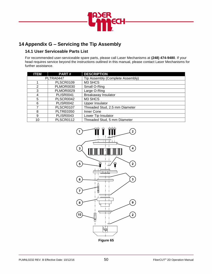
PLMNL0232 REV. B Effective Date: 10/12/16 50 FiberCUT® 2D Operation Manual
14 Appendix G – Servicing the Tip Assembly
14.1 User Serviceable Parts List
For recommended user-serviceable spare parts, please call Laser Mechanisms at (248) 474-9480. If your head requires service beyond the instructions outlined in this manual, please contact Laser Mechanisms for further assistance.
ITEM PART # DESCRIPTION
PLTRA0447 Tip Assembly (Complete Assembly)
1 PLSCR0109 M3 SHCS
2 PLMOR0030 Small O-Ring
3 PLMOR0029 Large O-Ring
4 PLISR0041 Breakaway Insulator
5 PLSCR0042 M3 SHCS
6 PLISR0042 Upper Insulator
7 PLSCR0107 Threaded Stud, 2.5 mm Diameter
8 PLTRE0350 Inner Cone
9 PLISR0043 Lower Tip Insulator
10 PLSCR0112 Threaded Stud, 5 mm Diameter
Figure 65

PLMNL0232 REV. B Effective Date: 10/12/16 51 FiberCUT® 2D Operation Manual
14.2 Rebuilding the Tip Assembly
To disassemble the tip assembly:
1. Remove the tip assembly from the head according to Section 5.4.
For steps 2 to 13, see Figure 66.
2. Unthread the tip retainer nut assembly and gas jet tip from the outer body.
3. Remove the (6) M3 SHCS (PLSCR0109) that secure the breakaway insulator (PLISR0041) to the tip assembly.
4. Remove the tip retainer nut and the breakaway insulator with the o-rings from the tip retainer nut.
5. Inspect the large o-ring (PLMOR0029) and the small o-ring (PLMOR0030) in the breakaway insulator.
Replace any worn or damaged o-rings.
6. Inspect the large o-ring (PLMOR0029) and the small o-ring (PLMOR0030) in the top plate.
Replace any worn or damaged o-rings.
7. Remove the (3) M3 SHCS (PLSCR0042) that secure the top plate to the outer body.
8. Remove the upper insulator (PLISR0042).
It may remain on top of the inner cone (PLTRE0350).
It may remain on or fall off of the bottom of the upper insulator.
9. Inspect the small o-ring (PLMOR0030) in the outer body.
Replace it if it is worn or damaged.
10. Unthread the 5 mm (larger) gold post (PLSCR0107) from the outer body.
11. Unthread the 2.5 mm (smaller) gold post (PLSCR0112) from the inner cone.
12. Remove the inner cone (PLTRE0350) and lower tip insulator (PLISR0043) from the outer body.
13. Inspect the large o-ring (PLMOR0029) in the inner cone.
Replace it if it is worn or damaged.
14. If desired, remove and/or replace the gas jet tip according to Section 5.1.
Figure 66

PLMNL0232 REV. B Effective Date: 10/12/16 52 FiberCUT® 2D Operation Manual
To reassemble the tip assembly:
Worn or damaged o-rings were replaced during the disassembly procedure.
Replace any other worn or damaged components during the reassembly procedure.
For steps 16 to 27, see Figure 66.
15. If necessary, replace the gas jet tip and/or tip retainer nut assembly according to Section 5.1.
16. Thread the 2.5 mm (smaller) gold post (PLSCR0112) into the inner cone.
17. Push the lower tip insulator (PLISR0043) onto the inner cone (PLTRE0350) so that the inner cone alignment tab seats in the lower tip insulator alignment notch.
18. Orient the outer body so the alignment flat (with the Laser Mechanisms logo) faces you.
19. Insert the lower tip insulator and inner cone with threaded stud into the outer body so that the gold post is on your left.
20. Thread the tip retainer nut assembly and gas jet tip onto the outer body.
21. Thread the 5 mm (larger) gold post (PLSCR0107) into the outer body.
22. Insert the upper insulator (PLISR0042) so that the smaller gold post is aligned with the upper insulator hole.
The notch should approximately face the back of the tip assembly.
23. Insert the upper plate so that the (2) alignment holes are aligned with the (2) gold posts.
24. Replace the (3) M3 SHCS (PLSCR0042) that secure the top plate to the outer body.
You will see (3) counterbores.
25. Insert the breakaway insulator (PLISR0041) into the retainer nut.
26. Align the breakaway insulator and retainer nut so that the breakaway insulator alignment holes are in line with the gold posts.
You will see (6) counterbores.
27. Replace the (6) M3 SHCS (PLSCR0109) that secure the breakaway insulator to the top plate.
28. Replace the tip assembly on the head according to Section 5.4.

PLMNL0232 REV. B Effective Date: 10/12/16 53 FiberCUT® 2D Operation Manual
15 Glossary
Aiming Beam
A low power, visible red beam used to indicate the position of the high-powered laser beam.
Assist Gas
Coaxial gas that flows through the nozzle (gas jet tip) orifice to aid the cutting process and evacuate molten material from the kerf.
Air Blast
A stream of air to keep debris out of the cutting area while piercing.
CFN
Cold Formed Nozzle
Collimator
An assembly with optics that converts diverging light into collimated (parallel) light within the head.
Cover Glass
A consumable optic used to protect more expensive optics in the head.
Double Nozzle
A nozzle or gas jet tip that includes an insert to enhance the cutting performance.
Fiber Input Adapter
An assembly that connects a specific type of fiber to the head.
FL
Focal Length
Focal Point
The point at which the light rays refracted by a lens or reflected by a mirror, intersects and produces the highest concentration of energy.
GJT
Gas Jet Tip
HSU
Height Sensing Unit
IC
Integrated Circuit
I/O
Inputs(s) and Output(s)
LHCS
Low head Cap Screw
PCB
Printed Control Board
PSI
Pounds per Square Inch
Purge Gas
Gas used to positively pressurize the inside of the head to keep debris from entering.
SHCS
Socket Head Cap Screw
TRA
Tip Retainer Assembly
TRN
Tip Retainer Nut

PLMNL0232 REV. B Effective Date: 10/12/16 54 FiberCUT® 2D Operation Manual
This Page Is Intentionally Left Blank

Laser Mechanisms, Inc.
25325 Regency Drive • Novi, Michigan 48375 USA
Phone: (248) 474-9480 • Fax: (248) 474-9277
In Europe: Phone: +32(0)92 18 70 70 • Fax: +32(0)92 18 70 79
Web: www.lasermech.com • E-Mail: [email protected]


![Curso de Autodesk Autocad® - Cursos de Diseño Gráfico ...Curso de Autodesk Autocad® 2D 30 HRS Autodesk Autocad® 2D Autodesk Autocad® [ Diseño y documentación de planos ] 30](https://img.dokumen.tips/doc/110x75/60bf32457f62ce72bb78f8cb/curso-de-autodesk-autocad-cursos-de-diseo-grfico-curso-de-autodesk-autocad.jpg)