Embed Size (px)
Citation preview

p/n 003-695, Issue 4
STANDARD RECOMMENDED PROCEDURE 003-695 | ISSUE 4 | January 2012 | PAGE 1 OF 11
| PR
ETE
RM
INAT
ED
SY
STE
MS
| C
AB
LES
| C
ON
NE
CTO
RS
| C
aB
LE a
SS
EM
BLI
ES
| H
AR
DW
AR
E |
TOO
L K
ITS
AN
D A
CC
ES
SO
RIE
S |
TES
T E
QU
IPM
EN
T | S
PLI
CE
EQ
UIP
ME
NT
| FA
N-O
UT
KIT
S |
TRA
ININ
GFiber Zone Box
related literature |
1. Tools and MaTerials• Panel-lifter (suction cup for laminate panels or hook-and-loop for carpeted panels) for
accessing the raised floor.• Screwdriver and other standard tools (pliers, etc.)• Mounting hardware is not provided. The type of hardware used depends on the mounting
location; wall anchors may be required for adequate support on sheetrock walls.
2. CoMponenTs
Figure 1
Quick-release latches on each corner of the inner tray allow the tray to be removed from the cabinet for ease of fiber routing, if desired.
The unit is 21 inches wide by 21 inches high by 9 inches deep. It weights 11 kg (24 pounds).
4 Wall-mountingBrackets
Tiltable 19-inch Frame 4 RadiusControl Guides
Fan-out Bracket(Two bracketsmay be installed.Each bracketholds up to 12 BTF kits.)
Record LabelDoor Latch
Quick-release Latches Ground Stud
Universal Cable Clamp
KPA-2409
STANDARD RECOMMENDED PROCEDURE 003-695 | ISSUE 4 | January 2012 | PAGE 2 OF 11
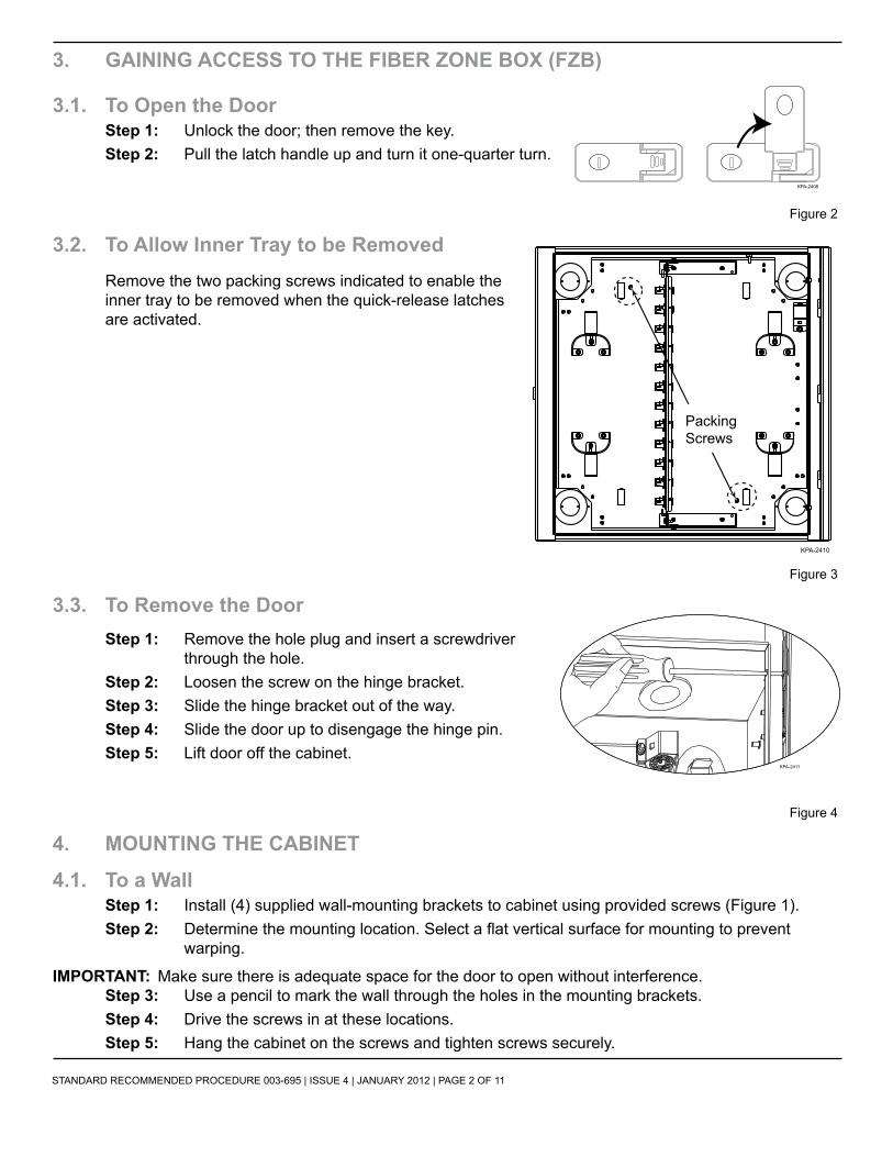
3. gaining aCCess To The Fiber Zone box (FZb)
3.1. To open the doorstep 1: Unlock the door; then remove the key.step 2: Pull the latch handle up and turn it one-quarter turn.
Figure 2
3.2. To allow inner Tray to be removed remove the two packing screws indicated to enable the inner tray to be removed when the quick-release latches are activated.
Figure 3
3.3. To remove the doorstep 1: remove the hole plug and insert a screwdriver
through the hole.step 2: Loosen the screw on the hinge bracket.step 3: Slide the hinge bracket out of the way.step 4: Slide the door up to disengage the hinge pin.step 5: Lift door off the cabinet.
Figure 4
4. MounTing The CabineT
4.1. To a Wallstep 1: Install (4) supplied wall-mounting brackets to cabinet using provided screws (Figure 1).step 2: Determine the mounting location. Select a flat vertical surface for mounting to prevent
warping.
iMporTanT: Make sure there is adequate space for the door to open without interference.step 3: Use a pencil to mark the wall through the holes in the mounting brackets.step 4: Drive the screws in at these locations.step 5: Hang the cabinet on the screws and tighten screws securely.
KPA-2408
Packing Screws
KPA-2410
KPA-2411

STANDARD RECOMMENDED PROCEDURE 003-695 | ISSUE 4 | January 2012 | PAGE 3 OF 11
4.2. underneath a raised Floor
4.2.1 direct Methodstep 1: Select an installation location and
remove five adjacent floor tiles in a “+” pattern using a panel-lift tool. The unit will be installed in the center of the “+.”
noTe: Although the FZB can be installed by removing only two floor tiles or panels (when it is not practical to remove more), removing five panels facilitates installation and inspection for obstacles.
Figure 5 step 2: Install provided floor trim plates (p/n 10-031423-
001) on both sides of the housing with provided screws.
Figure 6 step 3: Lower housing into center opening of
floor tiles. Opening the door and using the interior ledge of the housing as a handle may facilitate installation. The trim plates should rest directly on the floor system posts or “stanchions.”
step 4: Reinstall all floor tiles with the panel-lifter tool. Ensure tiles are even with adjacent tiles. If the floor tile over the FZB will not lay flat and even, it may be necessary to install the box below the stringers as described in Section 4.2.3.
iMporTanT: Due to variations in raised floor systems, installation sequences may deviate from this direct installation method. If necessary, proceed to Section 4.2.2 or 4.2.3 for alternative installation methods.
Figure 7
TPA-3999
TPA-4001
TPA-4000

STANDARD RECOMMENDED PROCEDURE 003-695 | ISSUE 4 | January 2012 | PAGE 4 OF 11
4.2.2 alternative Method 1If unable to successfully install the unit under a raised floor following the instructions in Section 4.2.1:
Figure 8
step 1: Remove one of the trim plates and reinsert the housing into the center opening. Allow the side where the trim plate was removed to drop below the stringer on that side (Figure 8).
step 2: Position the trim plate into the gap between the stringer and the FZB. Reinstall the trim plate to the side of the unit with the provided screws (Figure 8 inset). (It may require two people to perform this operation.)
step 3: Reinstall all floor tiles with the panel-lifter tool. Ensure tiles are even with adjacent tiles. If the floor tile over the FZB will not lay flat and even, it may be necessary to install the box below the stringers as described in Section 4.2.3.
4.2.3 alternative Method 2With some raised floor systems and/or if desired, the FZB may be mounted directly to the substructure. If there are no cables or conduit running under the FZB, the bottom of the unit will rest directly on the substructure or concrete floor. Ensure there is enough depth for the top of the unit to be just below the stringers.
step 1: remove stringers, lower FZB into the opening below the level of the stringers, and reinstall the stringers.
step 2: Reinstall all floor tiles with the panel-lifter tool. Ensure tiles are even with adjacent tiles.
TPA-4002

STANDARD RECOMMENDED PROCEDURE 003-695 | ISSUE 4 | January 2012 | PAGE 5 OF 11
4.3. in a suspended CeilingIn a suspended ceiling, the door of the FZB can replace the tile for optimal accessibility. To do so, a ceiling trim plate kit ((p/n FZB-04U-CLG, ordered separately) must be installed onto the FZB.
noTe: Mounting hardware and supports are not included. Use framing members (threaded rod in conjunction with metal struts) or support wires compliant with NEC Article 314.23 D (Supports for Suspending Ceilings). Support wires must be capable of supporting a fully loaded FZB (maximum 50 lb.).
step 1: Install (4) supplied wallmount brackets to the FZB using the provided screws.
step 2: Install ceiling trim plate kit ((p/n FZB-04u CLG) as shown in Figure 9.
Figure 9
step 3: Determine mounting location of FZB in the ceiling and remove two ceiling panels or tiles (Figure 10).
Figure 10
step 4: Measure distance to building “red-iron” or other structural or supporting elements. Use this measurement, plus any slack length required for tieing the wire or installing nuts on threaded rod, to determine the length of each of the four support wires or rods.
step 5: Attach the tie wires (or threaded rod) to the supporting element. Tie wires are simply tied or wrapped around the supporting truss or girder. In the case of threaded rods, use a supporting bracket and hardware compliant with the manufacturer’s instructions.
TPA-4003
WallmountBrackets
Ceiling Trim Plates
TPA-4004

STANDARD RECOMMENDED PROCEDURE 003-695 | ISSUE 4 | January 2012 | PAGE 6 OF 11
step 6: Tilt the FZB at an angle to allow it to pass through with the trim plates and mounting brackets installed. Pass the box through the opening in the ceiling (Figure 11).
step 7: Position the box in place so that the trim plates rest directly on the suspended ceiling stringers or cross members while attaching the primary support wires or rods.
Figure 11
step 8: Pass the supporting tie wires or threaded rods through the mounting brackets (Figure 12). If using wire, simply pass the wire through the hole in the mounting bracket, loop back up, and make several wraps around the wire.
step 9: Adjust the tension by bending the wire with a pair of pliers. It is important not to allow the suspended ceiling stringers to bear the weight of the FZB.
Figure 12
noTe: If using threaded rods, it may be necessary to adjust the top or bottom supporting bolts/nuts.
step 10: Ensure the FZB is level and offset slightly from the stringers or cross-members so that the FZB is only slightly resting on the suspending ceiling.
step 11: reinstall the ceiling panels / tiles to complete the installation (Figure 13). Ensure that the door is properly closed and locked to prevent unauthorized access and harm from the door swinging down.
Figure 13
TPA-4006
TPA-4007
STANDARD RECOMMENDED PROCEDURE 003-695 | ISSUE 4 | January 2012 | PAGE 7 OF 11
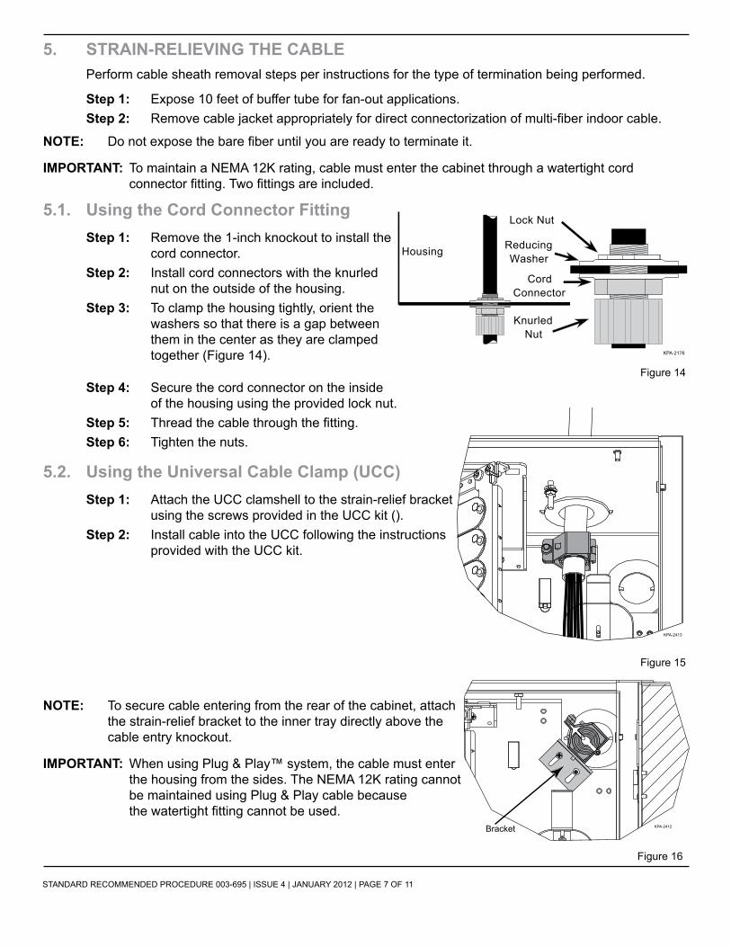
5. sTrain-relieving The CablePerform cable sheath removal steps per instructions for the type of termination being performed.
step 1: Expose 10 feet of buffer tube for fan-out applications.step 2: Remove cable jacket appropriately for direct connectorization of multi-fiber indoor cable.
noTe: Do not expose the bare fiber until you are ready to terminate it.
iMporTanT: To maintain a NEMA 12K rating, cable must enter the cabinet through a watertight cord connector fitting. Two fittings are included.
5.1. using the Cord Connector Fittingstep 1: remove the 1-inch knockout to install the
cord connector. step 2: Install cord connectors with the knurled
nut on the outside of the housing. step 3: To clamp the housing tightly, orient the
washers so that there is a gap between them in the center as they are clamped together (Figure 14).
Figure 14step 4: Secure the cord connector on the inside
of the housing using the provided lock nut.step 5: Thread the cable through the fitting.step 6: Tighten the nuts.
5.2. using the universal Cable Clamp (uCC)step 1: attach the uCC clamshell to the strain-relief bracket
using the screws provided in the UCC kit ().step 2: Install cable into the uCC following the instructions
provided with the UCC kit.
Figure 15
noTe: To secure cable entering from the rear of the cabinet, attach the strain-relief bracket to the inner tray directly above the cable entry knockout.
iMporTanT: When using Plug & Play™ system, the cable must enter the housing from the sides. The NEMA 12K rating cannot be maintained using Plug & Play cable because the watertight fitting cannot be used.
Figure 16
Housing
Lock Nut
ReducingWasher
CordConnector
KnurledNut
KPA-2176
KPA-2413
Bracket KPA-2412

STANDARD RECOMMENDED PROCEDURE 003-695 | ISSUE 4 | January 2012 | PAGE 8 OF 11
6. grounding arMored Cable
A ground kit (purchased separately is required for armored cable.
step 1: attach the ground wire to the cable armor according to the instructions provided with the ground kit.
step 2: attach the other end of the ground wire to the ground stud inside the cabinet (Figure 17).
step 3: Then, run a #6 AWG ground wire (purchased separately at any electrical supply store) from the ground stud to the primary building ground according to the local code authority.
Figure 17
iMporTanT: To maintain the NEMA 12K rating, the ground wire must utilize a watertight connector (purchased separately).
7. insTalling CableIf using the optional splicing kit, cables must enter from the top or bottom of the unit.
step 1: Remove the blank panels and install connector panels or modules into the unit.
noTe: Connector panels with connector adapters are purchased separately.
step 2: If fibers are not already connectorized, install connectors onto the fibers according to the instructions provided with the connectors. You may use the optional splicing kit (p/n FZB-SPLC-85) to splice stubbed modules or pigtails to the cables. Refer to the instructions provided with the kit for fiber routing configurations. Refer to the instructions provided with the splice trays for fiber strip lengths and routing inside the trays.
step 3: Clean the connectors as described in this section and install them into the connector panels. You may lift up on the 19-inch frame and secure it in a slanted position to make it easier to install connectors into the panel.
noTe: Obey the following precautions in order not to damage the surface of the connector and make it unusable:
• Use a clean tissue soaked in alcohol to gently clean the connector. Do not press heavily on it as you clean.
• Dry the connector prior to installation by using a dry tissue or blowing it dry with compressed air.
• Clean all areas that will contact the connector adapter.• Do not force the connector into the receptacle. If the connector does not fit easily into the
receptacle, back it out and reinstall.• Install threaded connectors into the adapter and tighten. Do not OVERTIGHTEN. Do not allow
the connector body (ferrule) to turn as you screw it into place. This causes the surfaces to grind against each other.
step 4: Route the fiber around the fiber guides on the inner tray. Make sure there is adequate slack so that the fiber bend radius is maintained across the routing guides. Refer to Figure 18 for examples of routing configurations.
Ground Wire
KPA-2414

STANDARD RECOMMENDED PROCEDURE 003-695 | ISSUE 4 | January 2012 | PAGE 9 OF 11
Side Entry Top Entry
Figure 18
step 5: When installing cable for the Plug & Play™ system, route to modules as shown in Figure 19.
Side Entry Top Entry
Figure 19
8. insTalling buFFer Tube Fan-ouT bodiesnoTe: Loose-tube fiber optic cable can be installed using buffer tube fan-out (BTF) kits (purchased
separately). The FZB unit allows termination of distribution cable using kits. Up to twelve BTF kits can be installed on each fan-out bracket.
step 1: Install the fan-out bracket using the provided screws.step 2: Route the buffer tubes around the guides.
KPA-2415 KPA-2416
KPA-2417 KPA-2418

STANDARD RECOMMENDED PROCEDURE 003-695 | ISSUE 4 | January 2012 | PAGE 10 OF 11
step 3: Position the buffer tubes against the fan-out bracket. Mark the location of the fan-out on the buffer tubes to determine the length required.
step 4: Install fan-out assemblies and connectors according to the instructions provided with the BTF kits.
step 5: Slide the fan-out bodies into the bracket and secure using a cable tie (Figure 20).
Figure 20
step 6: route the connectorized fan-out tubing around the guides and plug connectors into the connector panel (Figure 21). Refer to the connector care instructions in section 9.3 to clean the connectors and avoid damage to them during installation.
step 7: Record information appropriately on the record label on the inside of the door.
iMporTanT: Accurate record keeping is imperative for an organized installation.
Side Entry Top Entry
Figure 21
KPA-2419
Buffer Tubes
Buffer TubeFanout Bodies
Cable Tie
KPA-2420KPA-2421

STANDARD RECOMMENDED PROCEDURE 003-695 | ISSUE 4 | January 2012 | PAGE 11 OF 11
Corning Cable Systems LLC • PO Box 489 • Hickory, NC 28603-0489 USA 1-800-743-2671 • FAX +1-828-325-5060 • International +1-828-901-5000 • http://www.corning.com/cablesystems
Corning Cable Systems reserves the right to improve, enhance, and modify the features and specifications of Corning Cable Systems’ products without prior notification. Plug & Play is a trademark of Corning Cable Systems Brands, Inc. All other trademarks are the properties of their respective owners. Corning Cable Systems is ISO 9001 certified.
© 2012 Corning Cable Systems. All rights reserved. Published in Mexico.
9. MainTaining The equipMenTThe unit requires very little maintenance to make sure fibers and parts remain in good condition.• loose parts: Check nuts, bolts and screws for looseness and tighten.• Moisture: Check the housing for accumulated moisture and place moisture absorbent packets as
needed.• Fiber Bends: Check fiber optic cable to make sure bends do not violate the minimum bend radius.
Check cable for unnecessary strain. Check cable entries and exits for crimping or crushing.• documentation: Check record label to make sure it is clear and accurate.