Embed Size (px)
Citation preview

Introduction Cemented carbide is a compositematerial of hard carbides and a softbinder metal. The hard carbides in-clude those of Group V and Group VIelements, such as WC, TiC, Mo2C,TaC4, Cr3C2, VC, and NbC. The softbinder metal is usually cobalt, nickel,iron, or their mixture (Ref. 1). Ce-mented carbide has been widely usedin aerospace, electronics, marine,petrochemical, mining, and automo-tive industries for decades in engineer-ing applications, such as pipe-valvecomponents, cutting tools, catalyticconverters, rock drill tips, and variouswear-resistant parts (Refs. 2, 3). Sever-
al methods have been used for joiningcemented carbide to steel substratesfor drill bits and cutting tools. Thesemethods include brazing (Refs. 4–6),sinterbonding (Ref. 7), or diffusionbonding (Refs. 8–10), chemical vapordeposition (Ref. 11), tungsten arcwelding (Ref. 12), friction welding(Ref. 13), and, more recently, laserwelding (Refs. 14–17). The challenge in joining cementedcarbide and steel dissimilar materialsis the low strength and poor ductilityof the metallic bond. The strength ofbrazed joints usually ranges from 150to 250 MPa (Ref. 5). With special braz-ing filler metals and pretreatment ofcemented carbide, the brazed joint
strength can achieve 370 MPa. Okitaet al. (Ref. 13) adapted friction welding to join the cemented carbideand steel. A tool steel was frictionwelded to cemented carbide with anintermediate layer that was dispersionstrengthened by tungsten carbide par-ticles in a nickel matrix. The joint ten-sile strength was found to be greaterthan 730 MPa when the forge pressurewas lower than 250 MPa, but thestrength markedly decreased when theforge pressure was greater than 300MPa. Tian et al. (Ref. 14) studied dip sol-dering and welding of carboloy andsteel dissimilar materials. Combininglaser fusion welding with dip solder-ing, they found fewer fissures in car-boloy, and laser fusion welding couldsuppress polycrystalline formation inthe binding Co, and thus improve thewelded joint toughness. Research byBarbatti et al. (Ref. 17) indicated thatlaser beam welding allowed the suc-cessful autogenous joining of a steel tocemented carbide. By welding with apreheating and postweld heat treat-ment, the temperature gradients werecontrolled, and lower residual stresslevel, crack-free, and nonporous, jointswere obtained. The mechanical prop-erties of the joints were found to becomparable with those of the conven-tional brazed steel-cemented carbidejoints. Costa et al. (Refs. 15, 16) foundthe major defects during laser welding
WELDING RESEARCH
JANUARY 2017 / WELDING JOURNAL 1-s
SUPPLEMENT TO THE WELDING JOURNAL, JANUARY 2017Sponsored by the American Welding Society and the Welding Research Council
This investigation focused on the factors that influence the strength and ductility of dissimilar joints
BY P. XU, D. ZHOU, AND L. LI
ABSTRACT Welding parameters were investigated for fiber laser welding of cemented carbideWCCo and steel dissimilar materials. The microstructure, composition, phase, and bendstrength of the joints were analyzed using optical metallography, scanning electronmicroscopy, xray diffraction, transmission electron microscopy, and bend testing. Theoptimized welding parameters included laser power of 2 kW, scanning speed at 0.96m/min, and heat input of 125 J/mm. The flexural bend strength and yield strength of thejoints attained 970 MPa and 876 MPa, much higher than that of conventional brazedjoints. The brittle fracture during bending occurred along the fusion boundary and HAZon the cemented carbide side, where dissolution of WC and penetration of Fe from the fusion zone are believed to have caused embrittlement at the WCmatrix interfaces.
KEYWORDS • Fiber Laser • Dissimilar Joints • Cemented Carbide • Brittle Fracture
P. XU and D. ZHOU are with Materials Science and Engineering, Shanghai University of Engineering Science, Shanghai, China, and L. LI ([email protected]) is with Chemical and Materials Engineering, University of Alberta, Edmonton, Canada.
Fiber Laser Welding of WCCo and Carbon SteelDissimilar Materials
Xu 12-16_Layout 1 12/8/16 2:05 PM Page 1

of WC-12%C cemented carbide to0.25%C steel to be misalignment,porosity, cracking, and excessive melt-through (for a specimen thickness of2.5 mm). The horizontal position ofthe laser beam interaction area wasidentified to be a major factor for jointquality. The quality was optimizedwhen the laser beam was positionedon the steel side with a distance of 0.2mm from the bond centerline. If thelaser beam interaction area was placedcloser to the hard metal, metal crack-ing was easily observed. However, ifthe laser beam was positioned fartherfrom the joint (greater than 0.2 mm),the parts did not fully join due to in-complete fusion. The microstructureof the fusion zone was found to be acellular dendritic structure with an eu-tectic mixture of austenite and com-plex carbides occupying the interden-dritic spaces of primary austenite den-drites. However, the strength and duc-tility of laser joints as influenced bydissimilar material welding mecha-nism have not been studied. With recent advancements of readi-ly accessible and efficient lasers, espe-cially fiber laser technology, the timehas come to make laser welding com-petitive relative to brazing for achiev-ing strong and possibly ductile joints.This paper provides the results of aninvestigation into the process parame-ters for fiber laser welding of WC-20Coto AISI 1045, both popular materialsfor engineering applications. The fo-cus was on the mechanism for joiningand the factors that influence thestrength and ductility of the dissimilarjoints.
Experimental Procedure
Materials and WeldingProcedure
The WC-20Co cemented carbidewas used as one of the base materials.The alloy has the following chemicalcomposition: 4.9C, 20Co, and 75.1W(wt-%). A carbon steel, AISI 1045, wasused as the other base material. Thecarbon steel has the following chemi-cal composition: 0.45C, 0.28Si,0.62Mn, 0.004S, 0.004P, 0.25Cr,0.25Cu, and balance Fe (wt-%). Disc-shaped base materials with a 50 mmdiameter and three thicknesses of 2, 3,
and 4 mm were brushed to a 2-mm sur-face roughness finish. These base met-al discs were cut into halves along thediameter and clamped to form a ce-mented carbide to carbon steel buttjoint with no root opening — Fig. 1. A 5-kW maximum output YLS-5000fiber laser (IPG, USA), with a KR60-HA robot system (Kuka, Germany),and a BIMO QBH laser processinghead (HIGHYAG, Germany), was usedto weld the butt joint. During the au-togenous welding, a copper backingstrip was used to support weld rootformation. The weld coupons wererigidly clamped to obtain low angulardistortions of the joints. The laserbeam focal point was varied from 0mm (on the surface of the plate) witha spot radius of 0.1 to –10 mm defo-cusing amount. A front and backshielding, provided by gas trailers, wassupplied with a high-purity argon gasat a flow rate of 15 to 25 L/min to pre-vent the molten pool and heat-affect-ed zone (HAZ) from oxidation. The
process parameters for laser weldingare shown in Table 1. Following weld-ing, the welded joints were evaluatedfor bead formation, incomplete fusion,microcracking in the fusion zone, orpossible liquation cracking in the WC-Co side of the HAZ.
Bend Test and MicrostructureAnalysis
Three-point bend strength wasmeasured using a Zwick BTC-T1-FR020TN.A50 universal testing frame(Zwick, Germany) that is stepper mo-tor driven and with a 20-kN load cell.The welded specimens were cut intobend test coupons with dimensions of48 × 4 × 2 mm (specimens A2-2, A2-8,and A2-9) or 48 × 4 × 3 mm (speci-mens B3-2). The as-welded surfaceswere ground along the longitudinalaxis of the test coupons. The length ofthe three-point bend test span (L) was36 mm. All coupons were tested inface-bend configuration at ambient
WELDING RESEARCH
WELDING JOURNAL / JANUARY 2017, VOL. 962-s
Fig. 2 — Front side weld formation for specimens with preheating. A — A11; B — A12;C — A14; and weld formation for specimens without preheating. D — A28; E — A24;and F — A21.
Fig. 1 — Schematic of laser welding specimen.
A
B
C
D
E
F
Xu 12-16_Layout 1 12/8/16 2:05 PM Page 2
temperature (20°C) at a constantcrosshead velocity of 0.05 mm/minwith a data acquisition rate of onesample per second. The flexural stress(sf) and flexural strain (f) at the outerfiber of the bend coupons are calculat-ed by
(1)and
(2)where P is the measured load, L is thesupport span, b is the width and d isthe thickness of the specimen cross-section, and d is the measured deflec-tion along the loading direction. Theflexural yield strength (sY) was deter-mined at the 0.2% strain offset; theflexural bend strength (sT) was deter-mined from the peak point of eachstress-strain curve.
The microstructure of the laserwelds was characterized by x-ray dif-fraction (XRD), optical metallography,scanning electron microscopy (SEM),and transmission electron microscopy(TEM). The XRD measurements werecarried out on weld samples using anX’Pert PRO X-ray diffractometer with aCu Ka radiation (l = 0.15406 nm) anda BLK2 cooling cycle system. The scan-ning step size was 0.026 deg, and thescanning range was 15 to 120 deg con-tinuous. The scanning speed was0.438 deg/s. For the SEM, the currentand voltage were at 40 mA and 40 kV,respectively. The optical microscopy and SEMspecimens were prepared by mounting,grinding and polishing, and etchingwith the Murakami’s reagent (10 gpotassium ferricyanide K3Fe(CN)6, 10 g sodium hydroxide NaOH, and 100mL water, freshly prepared) (Ref. 27).High-resolution microstructure of the
as-welded fusion zone was character-ized using a JEM 2010 TEM (JEOL,Japan). Samples for TEM were pre-pared using ion milling. The TEM pa-rameters were 200-kV acceleration volt-age, 96-mA dark current, 128-mA emis-sion current, 109.8-pA/cm2 currentdensity, 2-s exposure time, and magni-fications between 20k and 200k times.
ResultsWeld Formation
The weld penetration and bead for-mation are affected by welding param-eters (Table 1). The laser spot positionwas found to influence the fusion ofthe dissimilar materials. As the melt-ing point of WC (approx. 2700°C) ismuch higher than that of carbon steel(approx. 1350°C), the laser spot needsto be located at 1 mm from the buttjoint line toward the cemented carbide
d
L
6f 2ε δ
=
PL
bd
3
2f 2σ =
WELDING RESEARCH
JANUARY 2017 / WELDING JOURNAL 3-s
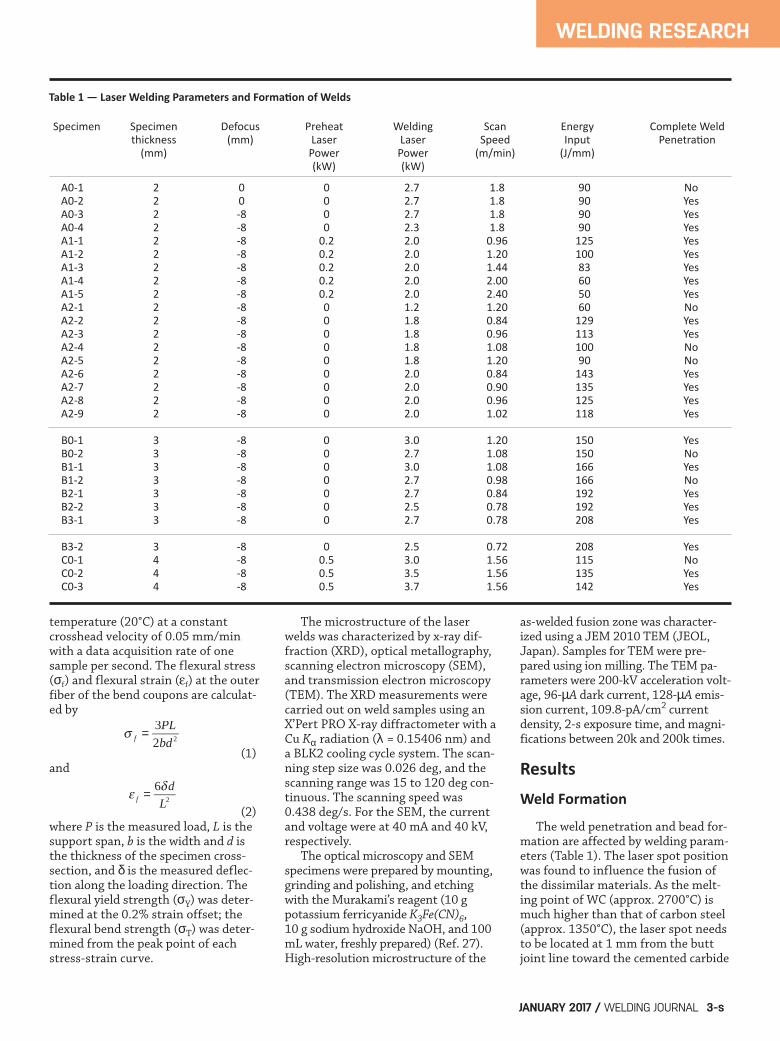
Table 1 — Laser Welding Parameters and Formation of Welds
Specimen Specimen Defocus Preheat Welding Scan Energy Complete Weld thickness (mm) Laser Laser Speed Input Penetration (mm) Power Power (m/min) (J/mm) (kW) (kW)
A01 2 0 0 2.7 1.8 90 No A02 2 0 0 2.7 1.8 90 Yes A03 2 8 0 2.7 1.8 90 Yes A04 2 8 0 2.3 1.8 90 Yes A11 2 8 0.2 2.0 0.96 125 Yes A12 2 8 0.2 2.0 1.20 100 Yes A13 2 8 0.2 2.0 1.44 83 Yes A14 2 8 0.2 2.0 2.00 60 Yes A15 2 8 0.2 2.0 2.40 50 Yes A21 2 8 0 1.2 1.20 60 No A22 2 8 0 1.8 0.84 129 Yes A23 2 8 0 1.8 0.96 113 Yes A24 2 8 0 1.8 1.08 100 No A25 2 8 0 1.8 1.20 90 No A26 2 8 0 2.0 0.84 143 Yes A27 2 8 0 2.0 0.90 135 Yes A28 2 8 0 2.0 0.96 125 Yes A29 2 8 0 2.0 1.02 118 Yes
B01 3 8 0 3.0 1.20 150 Yes B02 3 8 0 2.7 1.08 150 No B11 3 8 0 3.0 1.08 166 Yes B12 3 8 0 2.7 0.98 166 No B21 3 8 0 2.7 0.84 192 Yes B22 3 8 0 2.5 0.78 192 Yes B31 3 8 0 2.7 0.78 208 Yes
B32 3 8 0 2.5 0.72 208 Yes C01 4 8 0.5 3.0 1.56 115 No C02 4 8 0.5 3.5 1.56 135 Yes C03 4 8 0.5 3.7 1.56 142 Yes
Xu 12-16_Layout 1 12/8/16 2:05 PM Page 3

side. If the laser spot focuses at thesteel side (specimen A0-1) or on thebutt joint line (specimens A0-2, A0-3,and A0-4), incomplete fusion wasshown to have happened on the WCside. Among the welding parameters,the defocusing amount was found tobe a sensitive factor to influence theweld formation of WC-20Co cementedcarbide to AISI 1045 carbon steel. Theresults indicated that specimen A0-3(defocusing amount –8 mm below sur-face), in contrast with specimen A0-2(defocusing amount was zero, or onsurface), obtained complete joint pen-etration without weld spatter. There-fore, all subsequent welding trials wereconducted with a –8 mm defocusedlaser spot on the WC-Co side. Local preheating by a “dry-run” ofthe laser scan (i.e., all parameters keptthe same, except the laser power beingreduced to 1/10th of the level forwelding) was included in the weldingprocedure (Table 1). Figure 2 illus-trates the influence of preheating onthe weld formation during fiber laserwelding. The specimens with preheat-ing (specimens A1-1, A1-2, and A1-4)had consistently better penetrationthan those without preheating (speci-mens A2-1, A2-4, and A2-8). However,microcracks were observed on the sur-face of the cemented carbide HAZ ifthe preheat is combined with an in-crease of welding heat input (e.g.,specimen A1-1). The relative effect of laser powerand scan rate for a constant heat inputon weld formation was investigated(Table 1). With a heat input of 150J/mm, if the laser power is 2.7 kW andscan rate is 1.08 m/min (specimen B0-2), a good weld formation on the frontside but a poor penetration of weldbead on the back side were obtainedfor the 3-mm-thick specimens. Whilethe heat input was kept constant at150 J/mm, if the laser power was in-creased to 3.0 kW and scan rate in-creased to 1.20 m/min (specimen B0-1), complete penetration with goodweld formation was obtained. A simi-lar result was obtained for a constantheat input of 166 J/mm. With a laserpower of 2.7 kW and scan rate of 0.98m/min (specimen B1-2), insufficientpenetration was observed at the endof the weld; while complete joint pene-tration was obtained with an increasedlaser power to 3.0 kW and a increased
scan rate of 1.08 m/min (specimen B1-1). These results can be observed inFig. 3, which shows the weld forma-tion and penetration of specimens B0-1, B0-2, B1-1, and B1-2. Within therange of parameter variations in thisstudy, it seems that for a constant heatinput, increasing the laser power has agreater effect than decreasing thelaser scan rate, on enhancing the penetration. Figure 4 shows the changes in weldformation for specimens B2-1, B2-2,B3-1, and B3-2, when the heat inputwas increased from 192 J/mm to 208J/mm. The weld widths on the front
side are 2.39, 2.18, 2.5, and 2.29 mm,and the widths on the back side are1.26, 1.38, 1.2, and 1.31 mm, respec-tively. No cracks were observed incomplete-joint-penetration laser weldsexcept on specimen B3-1. Therefore,for 3-mm WC-20Co and AISI 1045steel laser welding, it is recommendedto use a heat input in the range of 192to 208 J/mm, and a laser power in therange of 2.5 to 2.7 kW. With the increase of plate thicknessto 4 mm, it becomes difficult to jointhe WC-20Co cemented carbide toAISI 1045 steel using the currentwelding setup. Poor penetration with
WELDING RESEARCH
WELDING JOURNAL / JANUARY 2017, VOL. 964-s
Fig. 3 — Front side weld formation. A — Specimen B01; C — Specimen B02; E — Specimen B11; and G — Specimen B12. Back side weld formation. B — Specimen B01; D —Specimen B02; F — Specimen 11; and H — Specimen B12.
Fig. 4 — Front side weld formation. A — Specimen B21; C — Specimen B22; E — Specimen B31; G — Specimen B32. Back side weld formation. B — Specimen B21; D — Specimen B22; F — Specimen B31; H — Specimen B32.
A
A
B
B
C
C
D
D
E
E
G
G
F
F
H
H
Xu 12-16_Layout 1 12/8/16 2:05 PM Page 4

unacceptable weld formation was ob-tained if the heat input was below 115J/mm. When the heat input was in-creased to above 134 J/mm, not onlylongitudinal microcracks, but also thetransverse microcracks were observedon the surface and cross sections ofthe laser fusion zones.
Microstructure of Joints
A typical joint has the nail-headshaped autogenous weld fusion zonewith a smooth top and root formation— Fig. 5. There is a greater dilutionfrom the steel side than from the WC-Co side. A micrograph of the fusionboundary region on the WC-Co side isshown in Fig. 6. The fusion zone onthe left side of the figure appears tohave solidified in primary dendriticand eutectic microstructure; the ce-mented carbide base material on theright side of the figure appears to haveretained the cubic and triangular WCparticles in the Co matrix. The fusionzone close to the AISI 1045 side fusionboundary also appears to have a pri-mary dendritic and eutectic mi-crostructure, but seems to show an in-
creased size for primary dendrites —Fig. 7. The center of the weld fusionzone shares a similar primary dendrit-ic and eutectic microstructure — Fig.8. A chemical analysis of the keypoints in the microstructure revealedthe primary dendrites to have thecomposition of a 0.7 wt-% carbon steelalloyed with 15 wt-% W and 5 wt-% Co(Table 2). It is evident from the darkneedles that the steel dendrites mayhave further transformed to marten-site-austenite constituents on-cooling— Fig. 8. The eutectic regions have atypical composition of 50 wt-% Fe, 45wt-% W, and a relatively higher C con-centration; therefore, it is reasonableto suggest one eutectic phase to beW(Fe)C carbide (Table 2). Specimens from the weld fusionzone were analyzed by XRD for crystalstructures — Fig. 9. The phases identi-fied in the fusion zone included a-fer-rite, martensite, Fe-containing car-bides (Fe3W3C and Fe6W6C), and asmall amount of MC (M being W andFe) carbide. Due to the overlappingpeaks of ferrite and martensite, theyremain to be differentiated. However,the high-carbon content in the den-
dritic regions seems to favor the iden-tification of the peaks due to marten-site. If ferrite was present at roomtemperature for this fusion zone, theextra carbon would have precipitatedas carbides, because the solubility ofcarbon in ferrite was low. There is noevidence of carbides in the primarydendritic regions under the resolutionof the BSE micrograph — Fig. 8. The phases in the fusion boundaryand HAZ of the WC-Co base materialwere identified from XRD of longitu-dinal specimens extracted parallel tothe welds — Fig. 10. The phase com-position for the HAZ is similar to thatof the weld fusion zone, including a-WC, some eutectic carbides (Fe3W3Cand Fe6W6C), and a weak indiction fora-Fe (ferrite) and martensite. Thedominant phase in the HAZ was WCcarbide, which was not significant inthe fusion zone. It was notable thatthe Co binding phase (of the HCPcrystal structure) in the base materialWC-Co was not detected in the HAZ.Significant alterations in the Co bind-ing phase in the WC-Co HAZ musthave happened during laser welding.
Bend Strength andFractography
Due to the statistical nature of me-chanical properties of cemented car-bides, four repeat specimens werebend-tested for each welded sample.Figure 11 summarizes the flexuralstress-flexural strain curves from thethree-point bend testing of typical
WELDING RESEARCH
JANUARY 2017 / WELDING JOURNAL 5-s
Table 2 — EDS Analysis of Chemical Composition for Locations Labeled in Fig. 8
Point Carbon Iron Cobalt Tungsten (wt%)(at%) (wt%)(at%) (wt%)(at%) (wt%)(at%)
A (0.61)(3.10) (78.95)(86.81) (4.61)(4.81) (15.83)(5.29) B (0.64)(4.20) (51.61)(73.07) (2.42)(3.24) (45.33)(19.49) C (0.75)(3.79) (80.01)(86.51) (4.86)(4.98) (14.37)(4.72)
Fig. 5 — Crosssectional view of a typical joint (A11) of AISI 1045(left side) and WCCo (right side).
Fig. 6 — Backscattered electron image of a typical joint near thefusion boundary on the WCCo side.
Xu 12-16_Layout 1 12/8/16 2:05 PM Page 5

joints. For 2-mm-thick sample A2-2,which was welded with a high heat in-put, all four specimens exhibited alinear stress-strain curve, the bendstrength falling between 311 and 508MPa, without showing any ductility— Fig. 11A. With the same heat input(achieved using an increased laserpower and increased scan speed), 2-mm-thick sample A2-8 exhibited notonly a much higher average bendstrength (about 826 MPa), but alsosignificant ductility — Fig. 11B. Com-pared with sample A2-8, a decreasedheat input for 2-mm-thick sample A2-9 resulted in three of the specimensto exhibit in low strength (375 MPaaverage) and one specimen exhibitinghigh strength and ductility — Fig.11C. Figure 11D shows the flexural stress-strain curves of 3-mm-thick specimenB3-2. The maximum and minimumbend strengths were 844.31 MPa and318.72 MPa with the range of plasticdeformation being 0.12 to 0.47 mm. Table 3 lists the flexural strength ofthe tested specimens. As can be seen,the maximum bend strength using op-timized welding parameters is 970MPa, and the minimum bend strengthis 312 MPa for 2-mm-thick specimens.Even the minimum bend strengthcompares favorably with reported typ-ical strength for brazed joints. Except for a few cases in which thespecimen contains hot-cracking de-fects in the fusion zone and the frac-ture happened in the fusion zone, allbend tested specimens fractured along
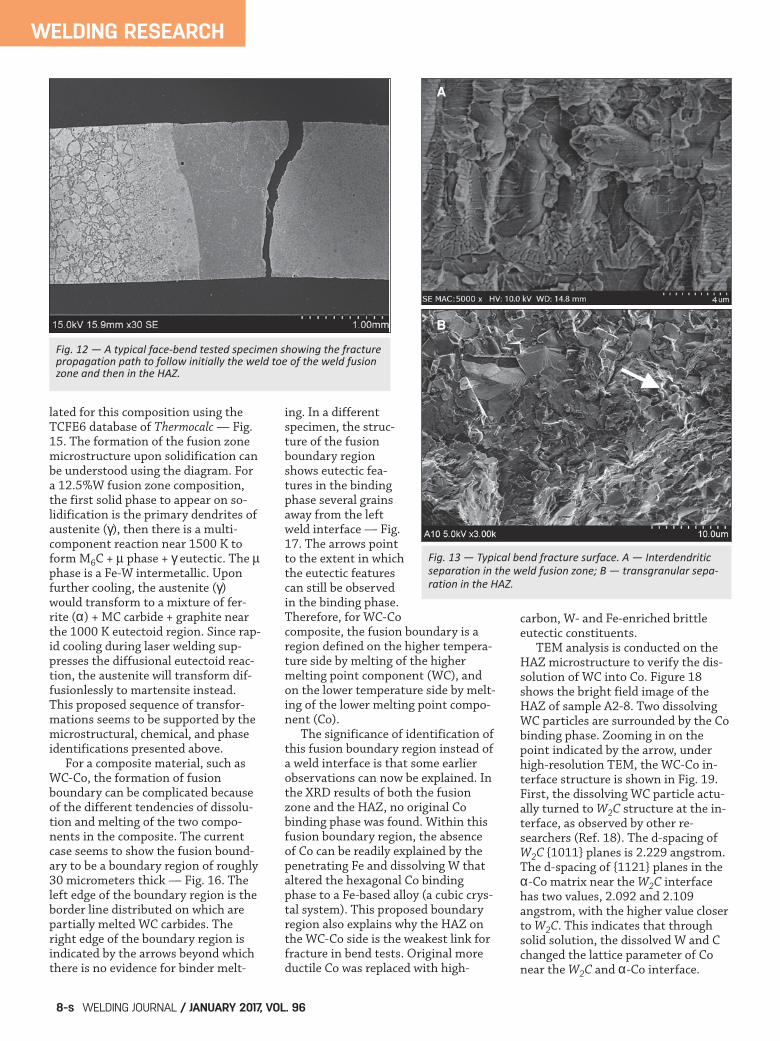
the fusion boundary on the WC-Coside. An example is shown in Fig. 12,in which the face-bend brittle fractureis shown to have started in the weldfusion zone near the weld toe, propa-gated across the fusion boundary, andgrown parallel to the fusion boundary,but always within the HAZ. The frac-tography of a typical fractured surfaceis shown in Fig. 13. In the weld fusionzone portion of the fracture, the frac-ture mode is intergranular — the frac-ture separates the interdendriticboundaries and reveals the tips of den-
dritic arms and the eutectic con-stituents — Fig. 13A. In the HAZ por-tion of the fracture, the fracture modeis transgranular — Fig. 13B. At a high-er magnification, the fracture in theHAZ showed the undissolved WC par-ticles separated in cleavage mode, andthe binding phase separated in mi-crovoid coalescence (dimple) mode,which showed some local ductility —Fig. 14. Near the right center of themicrograph, the arrow points to a clus-ter of as-solidified dendritic tips,which suggest the existence of mi-
WELDING RESEARCH
WELDING JOURNAL / JANUARY 2017, VOL. 966-s
Fig. 7 — Backscattered electron image of a typical joint near thefusion boundary on the AISI 1045 side.
Fig. 8 — Backscattered electron image of the center of the fusion zone of specimen B32. EDS analysis of labeled locations isshown in Table 2.
Table 3 — Flexural Bend Strength of the AsWelded Specimens
Specimen ID Elastic Modulus Yield Strength Tensile Strength (GPa) (MPa) (MPa)
A2201 256.94 – 473.05 A2202 247.31 – 508.00 A2203 224.24 – 440.46 A2204 246.98 – 311.60
A2801 249.28 731.71 867.59 A2802 285.97 – 701.21 A2803 267.20 875.96 970.06 A2804 251.47 – 686.20
A2901 272.16 – 365.10 A2902 270.21 842.88 880.01 A2903 271.14 – 417.22 A2904 269.26 – 343.95
B3201 214.21 827.77 827.77 B3202 197.92 – 318.72 B3203 200.35 – 639.71 B3204 191.14 834.70 844.31
Xu 12-16_Layout 1 12/8/16 2:05 PM Page 6
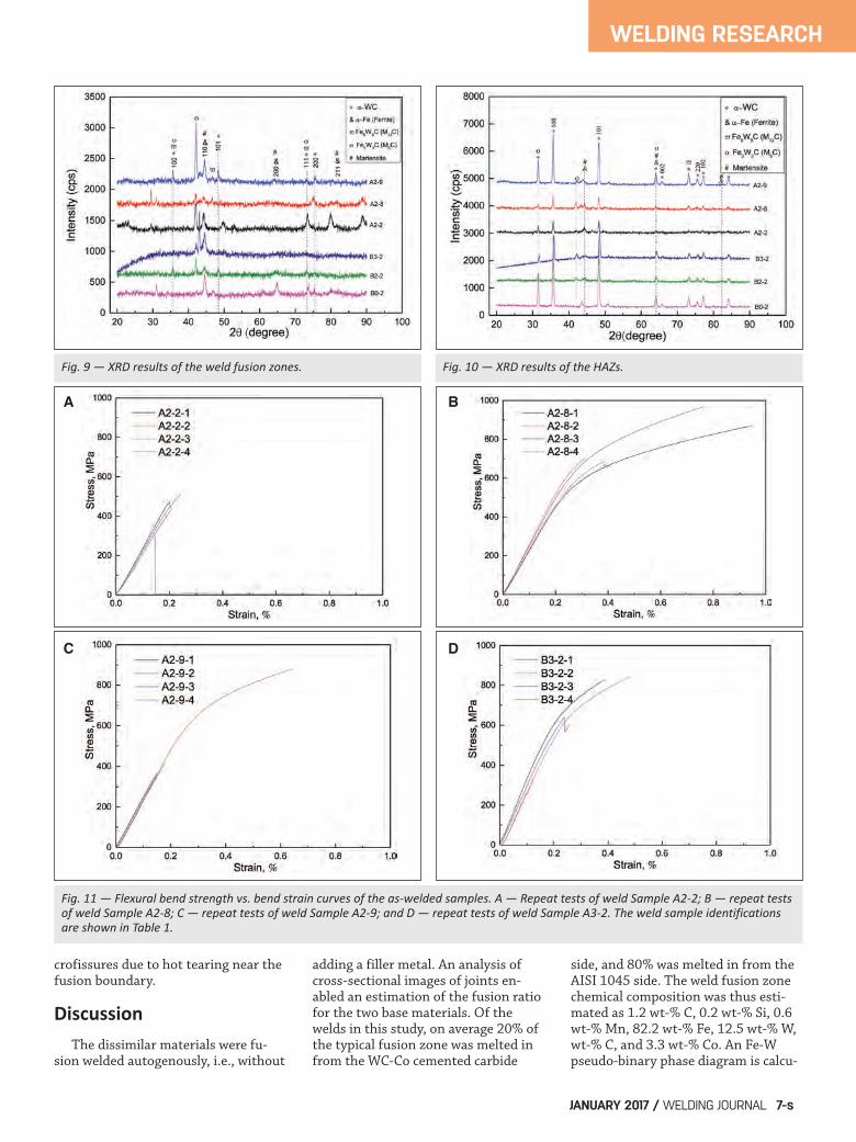
crofissures due to hot tearing near thefusion boundary.
Discussion The dissimilar materials were fu-sion welded autogenously, i.e., without
adding a filler metal. An analysis ofcross-sectional images of joints en-abled an estimation of the fusion ratiofor the two base materials. Of thewelds in this study, on average 20% ofthe typical fusion zone was melted infrom the WC-Co cemented carbide
side, and 80% was melted in from theAISI 1045 side. The weld fusion zonechemical composition was thus esti-mated as 1.2 wt-% C, 0.2 wt-% Si, 0.6wt-% Mn, 82.2 wt-% Fe, 12.5 wt-% W,wt-% C, and 3.3 wt-% Co. An Fe-Wpseudo-binary phase diagram is calcu-
WELDING RESEARCH
JANUARY 2017 / WELDING JOURNAL 7-s
Fig. 9 — XRD results of the weld fusion zones. Fig. 10 — XRD results of the HAZs.
Fig. 11 — Flexural bend strength vs. bend strain curves of the aswelded samples. A — Repeat tests of weld Sample A22; B — repeat testsof weld Sample A28; C — repeat tests of weld Sample A29; and D — repeat tests of weld Sample A32. The weld sample identificationsare shown in Table 1.
A B
C D
Xu 12-16_Layout 1 12/8/16 2:05 PM Page 7
lated for this composition using theTCFE6 database of Thermocalc — Fig.15. The formation of the fusion zonemicrostructure upon solidification canbe understood using the diagram. Fora 12.5%W fusion zone composition,the first solid phase to appear on so-lidification is the primary dendrites ofaustenite (g), then there is a multi-component reaction near 1500 K toform M6C + phase + g eutectic. The phase is a Fe-W intermetallic. Uponfurther cooling, the austenite (g)would transform to a mixture of fer-rite (a) + MC carbide + graphite nearthe 1000 K eutectoid region. Since rap-id cooling during laser welding sup-presses the diffusional eutectoid reac-tion, the austenite will transform dif-fusionlessly to martensite instead.This proposed sequence of transfor-mations seems to be supported by themicrostructural, chemical, and phaseidentifications presented above. For a composite material, such asWC-Co, the formation of fusionboundary can be complicated becauseof the different tendencies of dissolu-tion and melting of the two compo-nents in the composite. The currentcase seems to show the fusion bound-ary to be a boundary region of roughly30 micrometers thick — Fig. 16. Theleft edge of the boundary region is theborder line distributed on which arepartially melted WC carbides. Theright edge of the boundary region isindicated by the arrows beyond whichthere is no evidence for binder melt-
ing. In a differentspecimen, the struc-ture of the fusionboundary regionshows eutectic fea-tures in the bindingphase several grainsaway from the leftweld interface — Fig.17. The arrows pointto the extent in whichthe eutectic featurescan still be observedin the binding phase.Therefore, for WC-Cocomposite, the fusion boundary is aregion defined on the higher tempera-ture side by melting of the highermelting point component (WC), andon the lower temperature side by melt-ing of the lower melting point compo-nent (Co). The significance of identification ofthis fusion boundary region instead ofa weld interface is that some earlierobservations can now be explained. Inthe XRD results of both the fusionzone and the HAZ, no original Cobinding phase was found. Within thisfusion boundary region, the absenceof Co can be readily explained by thepenetrating Fe and dissolving W thataltered the hexagonal Co bindingphase to a Fe-based alloy (a cubic crys-tal system). This proposed boundaryregion also explains why the HAZ onthe WC-Co side is the weakest link forfracture in bend tests. Original moreductile Co was replaced with high-
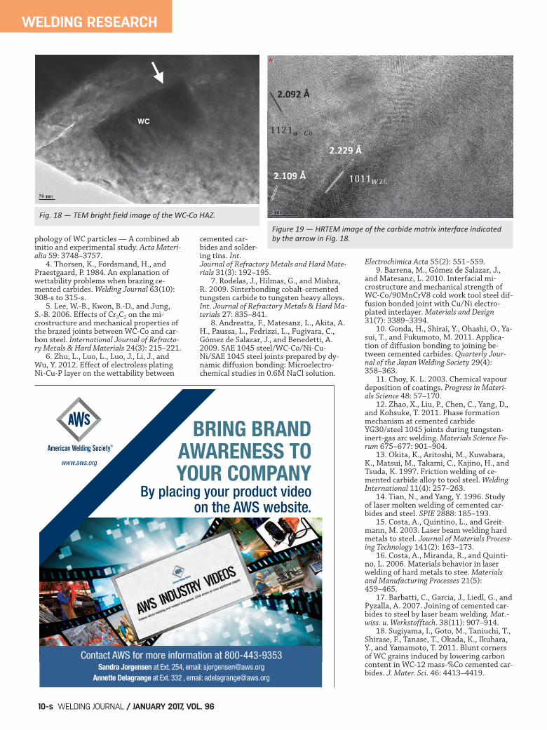
carbon, W- and Fe-enriched brittle eutectic constituents. TEM analysis is conducted on theHAZ microstructure to verify the dis-solution of WC into Co. Figure 18shows the bright field image of theHAZ of sample A2-8. Two dissolvingWC particles are surrounded by the Cobinding phase. Zooming in on thepoint indicated by the arrow, underhigh-resolution TEM, the WC-Co in-terface structure is shown in Fig. 19.First, the dissolving WC particle actu-ally turned to W2C structure at the in-terface, as observed by other re-searchers (Ref. 18). The d-spacing ofW2C {1011} planes is 2.229 angstrom.The d-spacing of {1121} planes in thea-Co matrix near the W2C interfacehas two values, 2.092 and 2.109angstrom, with the higher value closerto W2C. This indicates that throughsolid solution, the dissolved W and Cchanged the lattice parameter of Conear the W2C and a-Co interface.
WELDING RESEARCH
WELDING JOURNAL / JANUARY 2017, VOL. 968-s
Fig. 12 — A typical facebend tested specimen showing the fracturepropagation path to follow initially the weld toe of the weld fusionzone and then in the HAZ.
Fig. 13 — Typical bend fracture surface. A — Interdendriticseparation in the weld fusion zone; B — transgranular separation in the HAZ.
A
B
Xu 12-16_Layout 1 12/8/16 2:05 PM Page 8

Conclusions Three-mm-thick WC-Co and steeldissimilar materials were successfullywelded using fiber laser welding. Theoptimized welding parameters includelaser power of 2 kW, scanning speed at0.96 m/min, and the heat input of 125J/mm. The flexural bend strength andyield strength of the joints attained970 MPa and 876 MPa, much higherthan that of conventional brazedjoints. Brittle fracture during bendingoccured along the fusion boundaryand HAZ on the cemented carbideside, where dissolution of WC andpenetration of Fe from the fusion zoneare believed to have caused embrittle-ment at the WC-matrix interfaces.
The joint formation in a WC-Cocomposite seems to involve the forma-tion of a fusion boundary region thatis several WC grains wide (approxi-mately 30 micrometers). The highertemperature border of the fusionboundary region is defined by themelting point of WC. The lower tem-perature border of the fusion bound-ary region is defined by the meltingpoint of the Co binding phase.
The work was supported in part bythe National Natural Science Founda-tion of China (51475282, 51105240)
and “Shu Guang” project of ShanghaiMunicipal Education Commission andShanghai Education DevelopmentFoundation (13SG54).
1. Schroter, K. (Gen. Electric), Hard-metal alloy and the process of makingsame. U.S. patent, US67176423,1923.10.31. 2. Fang, Z., Wang, X., Ryu, T., Hwang,K. S., and Sohn, H. Y. 2009. Synthesis, sin-tering, and mechanical properties ofnanocrystalline cemented tungsten carbide— A review. International Journal of Refrac-tory Metals and Hard Materials 27(2):288–299. 3. Zhong, Y., Zhu, H., Shaw, L., andRamprasad, R. 2011. The equilibrium mor-
WELDING RESEARCH
JANUARY 2017 / WELDING JOURNAL 9-s
Fig. 14 — Transgranular separation in the HAZ. The WC particles fracture by cleavage; and the binding Co phase fracturesby microvoid coalescence (dimple) mode. The arrow points atdendritic tip features that indicate solidification microcracking.
Fig. 15 — FeW pseudobinary phase diagram calculated for a20% WC20Co and 80% AISI 1045 mixture.
Fig. 16 — The fusion boundary region in the WC20Co composite. Arrows point to the extent of penetration zone where thebinding phase contains darkcontrast, eutectic, constituents.
Fig. 17 — A backscattered electron image of the fusion boundaryon the WC20Co side. Arrows point to eutectic features in thebinding phase several grains away from the left weld interface.
Acknowledgments
References
Xu 12-16_Layout 1 12/8/16 2:05 PM Page 9
phology of WC particles — A combined abinitio and experimental study. Acta Materi-alia 59: 3748–3757. 4. Thorsen, K., Fordsmand, H., andPraestgaard, P. 1984. An explanation ofwettability problems when brazing ce-mented carbides. Welding Journal 63(10):308-s to 315-s. 5. Lee, W.-B., Kwon, B.-D., and Jung, S.-B. 2006. Effects of Cr3C2 on the mi-crostructure and mechanical properties ofthe brazed joints between WC-Co and car-bon steel. International Journal of Refracto-ry Metals & Hard Materials 24(3): 215–221. 6. Zhu, L., Luo, L., Luo, J., Li, J., andWu, Y. 2012. Effect of electroless platingNi-Cu-P layer on the wettability between
cemented car-bides and solder-ing tins. Int.Journal of Refractory Metals and Hard Mate-rials 31(3): 192–195. 7. Rodelas, J., Hilmas, G., and Mishra,R. 2009. Sinterbonding cobalt-cementedtungsten carbide to tungsten heavy alloys.Int. Journal of Refractory Metals & Hard Ma-terials 27: 835–841. 8. Andreatta, F., Matesanz, L., Akita, A.H., Paussa, L., Fedrizzi, L., Fugivara, C.,Gómez de Salazar, J., and Benedetti, A.2009. SAE 1045 steel/WC-Co/Ni-Cu-Ni/SAE 1045 steel joints prepared by dy-namic diffusion bonding: Microelectro-chemical studies in 0.6M NaCl solution.
Electrochimica Acta 55(2): 551–559. 9. Barrena, M., Gómez de Salazar, J.,and Matesanz, L. 2010. Interfacial mi-crostructure and mechanical strength ofWC-Co/90MnCrV8 cold work tool steel dif-fusion bonded joint with Cu/Ni electro-plated interlayer. Materials and Design31(7): 3389–3394. 10. Gonda, H., Shirai, Y., Ohashi, O., Ya-sui, T., and Fukumoto, M. 2011. Applica-tion of diffusion bonding to joining be-tween cemented carbides. Quarterly Jour-nal of the Japan Welding Society 29(4):358–363. 11. Choy, K. L. 2003. Chemical vapourdeposition of coatings. Progress in Materi-als Science 48: 57–170. 12. Zhao, X., Liu, P., Chen, C., Yang, D.,and Kohsuke, T. 2011. Phase formationmechanism at cemented carbideYG30/steel 1045 joints during tungsten-inert-gas arc welding. Materials Science Fo-rum 675–677: 901–904. 13. Okita, K., Aritoshi, M., Kuwabara,K., Matsui, M., Takami, C., Kajino, H., andTsuda, K. 1997. Friction welding of ce-mented carbide alloy to tool steel. WeldingInternational 11(4): 257–263. 14. Tian, N., and Yang, Y. 1996. Studyof laser molten welding of cemented car-bides and steel. SPIE 2888: 185–193. 15. Costa, A., Quintino, L., and Greit-mann, M. 2003. Laser beam welding hardmetals to steel. Journal of Materials Process-ing Technology 141(2): 163–173. 16. Costa, A., Miranda, R., and Quinti-no, L. 2006. Materials behavior in laserwelding of hard metals to stee. Materialsand Manufacturing Processes 21(5):459–465. 17. Barbatti, C., Garcia, J., Liedl, G., andPyzalla, A. 2007. Joining of cemented car-bides to steel by laser beam welding. Mat.-wiss. u. Werkstofftech. 38(11): 907–914. 18. Sugiyama, I., Goto, M., Taniuchi, T.,Shirase, F., Tanase, T., Okada, K., Ikuhara,Y., and Yamamoto, T. 2011. Blunt cornersof WC grains induced by lowering carboncontent in WC-12 mass-%Co cemented car-bides. J. Mater. Sci. 46: 4413–4419.
WELDING RESEARCH
WELDING JOURNAL / JANUARY 2017, VOL. 9610-s
� �
�
� �
�
���
� �
������
�
��
��������
�����
�
� �
�
� �
�
���
� �
� �
�
� �
�
���
� �
� �
�
� �
�
���
� � �� ��������
� �
�
� �
�
���
� ���
� �
�
� �
�
���
� �
� �
�
� �
�
���
� �
Fig. 18 — TEM bright field image of the WCCo HAZ.
Figure 19 — HRTEM image of the carbide matrix interface indicatedby the arrow in Fig. 18.
www.aws.org
American Welding Society®
BRING BRANDAWARENESS TOYOUR COMPANY
By placing your product videoon the AWS website.
Contact AWS for more information at 800-443-9353Sandra Jorgensen at Ext. 254, email: [email protected]
Annette Delagrange at Ext. 332 , email: [email protected]
Xu 12-16_Layout 1 12/8/16 2:05 PM Page 10