Embed Size (px)
Citation preview

8/8/2019 Fiber Customer Technology
http://slidepdf.com/reader/full/fiber-customer-technology 1/27
Opt ic a l Tec hnologies
Viscore Technologies Inc

8/8/2019 Fiber Customer Technology
http://slidepdf.com/reader/full/fiber-customer-technology 2/27
• Decibels (dB): unit of level (relative measure)•X dB is 10 -X/10 in linear dimension e.g. 3 dB Attenuation = 10 -.3 = 0.501
•Standard logarithmic unit for the ratio of two quantities. In optical fibers, the ratio is power and represents loss or gain.
• Decibels-milliwatt (dBm) : Decibel referenced to a milliwatt X mW is 10 ×log 10 ( X ) in dBm, Y dBm is 10 Y/10 in mW. 0dBm=1mW, 17dBm = 50mW
• Wavelength ( λ ): length of a wave in a particular medium.Common unit: nanometers, 10 -9 m (nm)
•300nm ( blue ) to 700nm ( red ) is visible. In fiber optics primarily use 850, 1310, &1550nm
• Frequency ( ν ): the number of times that a wave is produced within a particular time period. Common unit: TeraHertz, 10 12
cycles per second (Thz)•Wavelength x frequency = Speed of light ⇒ λ x ν = C
Termino logy

8/8/2019 Fiber Customer Technology
http://slidepdf.com/reader/full/fiber-customer-technology 3/27
• Attenuation = Loss of power in dB/km •The extent to which lighting intensity from the source is diminished as it passes through a given length of fiber-optic (FO) cable, tubing or light pipe. This specification determines how well a product transmits light and how much cable can be properly illuminated by a given light source.
• Chromatic Dispersion = Spread of light pulse in ps/nm-km
•The separation of light into its different coloured rays .
• ITU Grid = Standard set of wavelengths to be used in Fibre
Optic communications . Unit Ghz, e.g. 400Ghz, 200Ghz,100Ghz
• Optical Signal to Noise Ration (OSNR) = Ratio of
optical signal power to noise power for the receiver • Lambda = Name of Greek Letter used as Wavelength symbol ( λ )
• Optical Supervisory Channel (OSC) = Management
channel
More Term ino logy

8/8/2019 Fiber Customer Technology
http://slidepdf.com/reader/full/fiber-customer-technology 4/27
dB versus dBm
• dBm used for output power and receivesensitivity (Absolute Value)
• dB used for power gain or loss (Relative Value)

8/8/2019 Fiber Customer Technology
http://slidepdf.com/reader/full/fiber-customer-technology 5/27
Bi t Erro r Rat e ( BER)
• BER is a key objective of the Optical System Design
• Goal is to get from Tx to Rx with a BER < BER threshold of the Rx
• BER thresholds are on Data sheets
• Typical minimum acceptable rate is 10 -12

8/8/2019 Fiber Customer Technology
http://slidepdf.com/reader/full/fiber-customer-technology 6/27
Opt ic a l Budget
Optical Budget is affected by:
• Fiber attenuation
• Splices
• Patch Panels/Connectors
• Optical components (filters, amplifiers, etc)
• Bends in fiber • Contamination (dirt/oil on connectors)
Basic Optical Budget = Output Power – Input Sensitivity
Pout = +6 dBm R = -30 dBm
Budget = 36 dB

8/8/2019 Fiber Customer Technology
http://slidepdf.com/reader/full/fiber-customer-technology 7/27
Glass Pur i t y
Propagation Distance Need to Reduce theTransmitted Light Power by 50% (3 dB)
Window Glass 1 inch (~3 cm)
Optical Quality Glass 10 feet (~3 m)
Fiber Optics 9 miles (~14 km)
Fiber Optics Requires
Very High Purity Glass

8/8/2019 Fiber Customer Technology
http://slidepdf.com/reader/full/fiber-customer-technology 8/27
Attenuation
Dispersion
Nonlinearity
Waveform After 1000 KmTransmitted Data Waveform
Distortion
It May Be a Digital Signal, but It’s Analog Transmission
Fiber Fundam ent a ls
8/8/2019 Fiber Customer Technology
http://slidepdf.com/reader/full/fiber-customer-technology 9/27
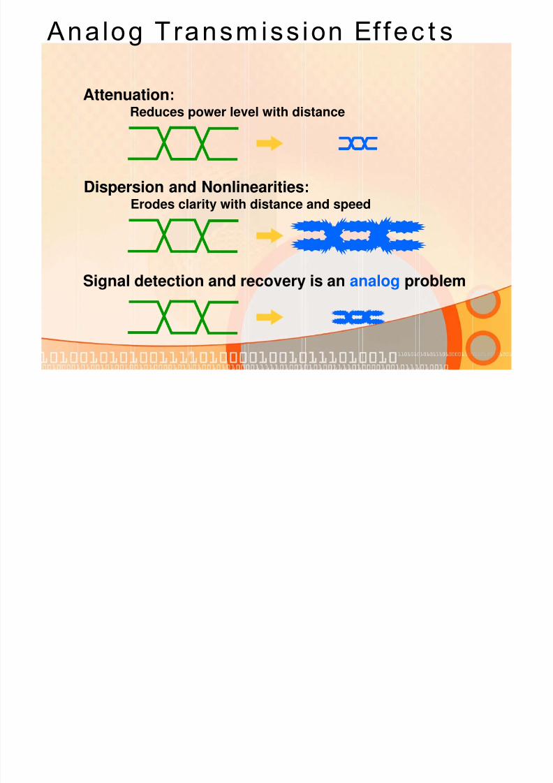
Attenuation:Reduces power level with distance
Dispersion and Nonlinearities:
Erodes clarity with distance and speed
Signal detection and recovery is an analog problem
Analog Transm iss ion Ef fec t s

8/8/2019 Fiber Customer Technology
http://slidepdf.com/reader/full/fiber-customer-technology 10/27
CladdingCore
Coating
Fiber Geom et ry
• An optical fiber is made of three sections:
• The core carries the
light signals • The cladding keeps the light
in the core
• The coating protects the glass

8/8/2019 Fiber Customer Technology
http://slidepdf.com/reader/full/fiber-customer-technology 11/27
θ1
n 2
n 1
Cladding
θ0 Core
Intensity Profile
Propaga t ion in Fiber
• Light propagates by total internal reflections at the core-cladding interface
• Total internal reflections are lossless
• Each allowed ray is a mode

8/8/2019 Fiber Customer Technology
http://slidepdf.com/reader/full/fiber-customer-technology 12/27
n 2
n 1
Cladding
Core
n 2
n 1
Cladding
Core
Dif ferent Types o f Fiber
• Multimode fiber •Core diameter varies
•50 mm for step index
•62.5 mm for graded index
•Bit rate-distance product >500 MHz-km
• Single-mode fiber
•Core diameter is about 9 mm
•Bit rate-distance product >100 THz-km

8/8/2019 Fiber Customer Technology
http://slidepdf.com/reader/full/fiber-customer-technology 13/27
• Light
• Ultraviolet (UV)
• Visible
• Infrared (IR)
• Communication wavelengths
• 850, 1310, 1550 nm
• Low-loss wavelengths
• Specialty wavelengths
• 980, 1480, 1625 nm
UV IR
Visible
850 nm
980 nm1310 nm
1480 nm
1550 nm1625 nm
λ125 GHz/nm
Wavelength: λ (nanometers)
Frequency: ƒ (terahertz)
C =ƒ x λ
Opt ic a l Spec t rum

8/8/2019 Fiber Customer Technology
http://slidepdf.com/reader/full/fiber-customer-technology 14/27
Opt ic a l A t t enuat ion
• Specified in loss per kilometer (dB/km)•0.40 dB/km at 1310 nm
•0.25 dB/km at 1550 nm
• Loss due to absorption by impurities
•1400 nm peak due to OH ions
• EDFA optical amplifiers available in 1550 window
1310Window
1550
Window

8/8/2019 Fiber Customer Technology
http://slidepdf.com/reader/full/fiber-customer-technology 15/27
T T
P i P0
Opt ic a l A t t enuat ion
• Pulse amplitude reduction limits “how
far” • Attenuation in dB
• Power is measured in dBm:
ExamplesExamples
10dBm10dBm 10 mW10 mW0 dBM0 dBM 1 mW1 mW
-3 dBm-3 dBm 500 uW500 uW
-10 dBm-10 dBm 100 uW100 uW
-30 dBm-30 dBm 1 uW1 uW
)

8/8/2019 Fiber Customer Technology
http://slidepdf.com/reader/full/fiber-customer-technology 16/27
• Polarization Mode Dispersion (PMD)Single-mode fiber supports two polarization states
Fast and slow axes have different group velocities
Causes spreading of the light pulse
• Chromatic DispersionDifferent wavelengths travel at different speeds
Causes spreading of the light pulse
Types of Dispers ion

8/8/2019 Fiber Customer Technology
http://slidepdf.com/reader/full/fiber-customer-technology 17/27
• Affects single channel and DWDM systems
• A pulse spreads as it travels down the fiber • Inter-symbol Interference (ISI) leads to
performance impairments
• Degradation depends on: • laser used (spectral width)
• bit-rate (temporal pulse separation)
• Different SM types
Interference
Chrom at ic Dispers ion

8/8/2019 Fiber Customer Technology
http://slidepdf.com/reader/full/fiber-customer-technology 18/27
60 Km SMF-28
4 Km SMF-28
10 Gbps
40 Gbps
L im i t a t ions From CD
t
t
• Dispersion causes pulse distortion,pulse "smearing" effects
• Higher bit-rates and shorter pulses are lessrobust to Chromatic Dispersion
• Limits "how fast“ and “how far”

8/8/2019 Fiber Customer Technology
http://slidepdf.com/reader/full/fiber-customer-technology 19/27
Com bat ing CD
• Use DSF and NZDSF fibers
•(G.653 & G.655)• Dispersion Compensating Fiber
• Transmitters with narrow spectral width

8/8/2019 Fiber Customer Technology
http://slidepdf.com/reader/full/fiber-customer-technology 20/27
Dispers ion Com pensat ing Fiber
• Dispersion Compensating Fiber:
• By joining fibers with CD of opposite signs (polarity) and suitable lengths an average dispersion close to zero can be obtained; the compensating fiber can be several kilometers and the reel can be inserted at any point in the link, at the receiver or at the transmitter

8/8/2019 Fiber Customer Technology
http://slidepdf.com/reader/full/fiber-customer-technology 21/27
Dispers ion Com pensat ion
Transmitter
Dispersion
Compensators
Dispersion Shifted Fiber Cable
+100
0
-100
-200
-300
-400
-500
C u m
u l a t i v e D i s p e r s i o n ( p s / n m )
Total Dispersion Controlled
Distance fromTransmitter (km)
No CompensationWith Compensation

8/8/2019 Fiber Customer Technology
http://slidepdf.com/reader/full/fiber-customer-technology 22/27
Dist anc e L im i t a t ion
Distance (Km) =Specification of Transponder (ps/nm)
Coefficient of Dispersion of Fiber (ps/nm*km)
A laser signal with dispersion tolerance of 3400 ps/nm
is sent across a standard SMF fiber which has a Coefficient ofDispersion of 17 ps/nm*km.
It will reach 200 Km at maximum bandwidth.
Note that lower speeds will travel farther.

8/8/2019 Fiber Customer Technology
http://slidepdf.com/reader/full/fiber-customer-technology 23/27
Polar i zat ion Mode Dispers ion
• Caused by ovality of
core due to: •Manufacturing process
•Internal stress (cabling)
•External stress (trucks)
• Only discovered in the 90s
• Most older fiber not characterized for PMD

8/8/2019 Fiber Customer Technology
http://slidepdf.com/reader/full/fiber-customer-technology 24/27
The primary Difference is in the Chromatic Dispersion Characteristics
Solut ions for Fiber Types
•Good for TDM at 1310 nm
•OK for TDM at 1550 nm•OK for DWDM (With Dispersion Mgmt
•Good for CWDM (>8 wavelengths)
Extended Band
(G.652.C)(suppressed attenuation
in the traditional waterpeak region)
•OK for TDM at 1310 nm•Good for TDM at 1550 nm•Good for DWDM (C + L Bands)
NZDSF(G.655)
•OK for TDM at 1310 nm•Good for TDM at 1550 nm
•Bad for DWDM (C-Band)
DSF(G.653)
•Good for TDM at 1310 nm
•OK for TDM at 1550•OK for DWDM (With Dispersion Mgmt)
SMF
(G.652)
( )

8/8/2019 Fiber Customer Technology
http://slidepdf.com/reader/full/fiber-customer-technology 25/27
Polar izat ion Mode Dispers ion (PMD)
• The optical pulse tends to broaden as it travels down the fiber; this is a much weaker phenomenon than chromatic dispersion and it is of little relevance at bit rates of 10Gb/s or less
nx
nyEx
Ey
Pulse As It Enters the Fiber Spreaded Pulse As It Leaves the Fiber
C b t i PMD

8/8/2019 Fiber Customer Technology
http://slidepdf.com/reader/full/fiber-customer-technology 26/27
Com bat ing PMD
• Factors contributing to PMD • Bit Rate
• Fiber core symmetry
• Environmental factors
• Bends/stress in fiber
• Imperfections in fiber
• Solutions for PMD
• Improved fibers • Regeneration
• Follow manufacturer’s recommended installation techniques for the fiber cable
T f Si l M d Fib

8/8/2019 Fiber Customer Technology
http://slidepdf.com/reader/full/fiber-customer-technology 27/27
• SMF-28(e) (standard, 1310 nm optimized, G.652)•Most widely deployed so far, introduced in 1986, cheapest
• DSF (Dispersion Shifted, G.653)•Intended for single channel operation at 1550 nm
• NZDSF (Non-Zero Dispersion Shifted, G.655)•For WDM operation, optimized for 1550 nm region
• TrueWave, FreeLight, LEAF, TeraLight…•Latest generation fibers developed in mid 90’s
•For better performance with high capacity DWDM systems
• MetroCor, WideLight…
• Low PMD ULH fibers
Types of Single-Mode Fiber