Embed Size (px)
Citation preview

FIAT RITMO (BRAVO) Engine 1.4 Tjet

© 2007 - Fiat Group Automobiles S.p.A. All rights reserved. Distribution or reproduction by any means is forbidden. Fiat Auto S.p.A. shall not be liable for any involuntary errors or omissions in the publication. The information provided in this document is subject to continual updating: Fiat Auto S.p.A. shall not be liable for any consequences arising from use of superseded information This publication is for training purposes only. For technical information, complete and fully updated for servicing purposes, refer exclusively to the specific service manuals and service information for the vehicles concerned.
Training Academy – Mirafiori Motor Village P.za Cattaneo, 9 – 10137 – TORINO (Italy) Tel. +39 011.0044351 Fax. +39 011.0044230 Info at: [email protected] www.fiattraining.net
© 2007 Fiat Group S.p.A. – All rights reserved 2 / 165 FIAT BRAVO TJET

Fiat Group Automobiles S.p.A FIAT BRAVO TJet COURSE OUTLINE Training Academy
CONTENTS TECHNICAL DATA................................................................................................................ 4
FIRE 1.4 TJET 150 HP AND 120HP ENGINES..................................................................... 6
INTEGRATED ELECTRONIC INJECTION-IGNITION........................................................... 7 MECHANICS...........................................................................................................................................8 CIRCUITS/SYSTEMS .............................................................................................................................21 ELECTRICAL COMPONENTS ..................................................................................................................43
Actuators ........................................................................................................................................................ 73 ENGINE CONTROL................................................................................................................................96
Electronic diagnosis...................................................................................................................................... 119 PROCEDURE .....................................................................................................................................130
3 / 165 © 2007 Fiat Group S.p.A. - All rights reserved
Fiat Group Automobiles S.p.A FIAT BRAVO TJet COURSE OUTLINE Training Academy
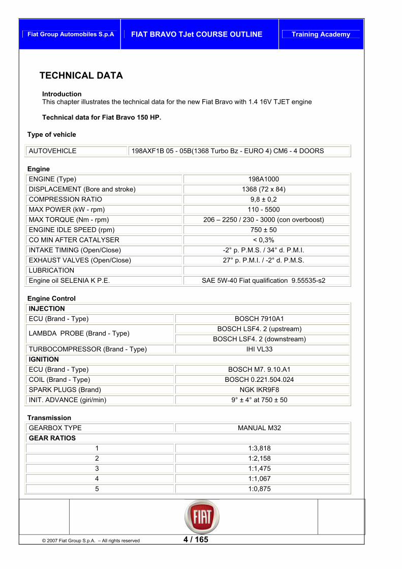
TECHNICAL DATA Introduction This chapter illustrates the technical data for the new Fiat Bravo with 1.4 16V TJET engine Technical data for Fiat Bravo 150 HP.
Type of vehicle
AUTOVEHICLE 198AXF1B 05 - 05B(1368 Turbo Bz - EURO 4) CM6 - 4 DOORS
Engine ENGINE (Type) 198A1000 DISPLACEMENT (Bore and stroke) 1368 (72 x 84) COMPRESSION RATIO 9,8 ± 0,2 MAX POWER (kW - rpm) 110 - 5500 MAX TORQUE (Nm - rpm) 206 – 2250 / 230 - 3000 (con overboost) ENGINE IDLE SPEED (rpm) 750 ± 50 CO MIN AFTER CATALYSER < 0,3% INTAKE TIMING (Open/Close) -2° p. P.M.S. / 34° d. P.M.I. EXHAUST VALVES (Open/Close) 27° p. P.M.I. / -2° d. P.M.S. LUBRICATION Engine oil SELENIA K P.E. SAE 5W-40 Fiat qualification 9.55535-s2
Engine Control INJECTION ECU (Brand - Type) BOSCH 7910A1
BOSCH LSF4. 2 (upstream) LAMBDA PROBE (Brand - Type) BOSCH LSF4. 2 (downstream)
TURBOCOMPRESSOR (Brand - Type) IHI VL33 IGNITION ECU (Brand - Type) BOSCH M7. 9.10.A1 COIL (Brand - Type) BOSCH 0.221.504.024 SPARK PLUGS (Brand) NGK IKR9F8 INIT. ADVANCE (giri/min) 9° ± 4° at 750 ± 50 Transmission
© 2007 Fiat Group S.p.A. – All rights reserved 4 / 165
GEARBOX TYPE MANUAL M32 GEAR RATIOS
1 1:3,818 2 1:2,158 3 1:1,475 4 1:1,067 5 1:0,875
Fiat Group Automobiles S.p.A FIAT BRAVO TJet COURSE OUTLINE Training Academy
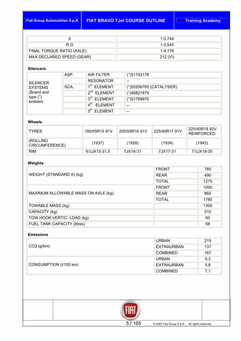
6 1:0,744 R.G 1:3,545
FINAL TORQUE RATIO (AXLE) 1:4,176 MAX DECLARED SPEED (GEAR) 212 (VI)
Silencers
ASP. AIR FILTER (°)51793178 RESONATOR -- SCA. 1st ELEMENT (°)55206760 (CATALYSER) 2nd ELEMENT (°)46821879 3rd ELEMENT (°)51789970 4th ELEMENT --
SILENCER SYSTEMS (Brand and type (°) emblem
5th ELEMENT --
Wheels
TYRES 195/65R15 91V 205/55R16 91V 225/45R17 91V 225/40R18 92V REINFORCED
(ROLLING CIRCUMFERENCE) (1937) (1928) (1934) (1943)
RIM 6½JX15-31,5 7JX16-31 7JX17-31 7½JX18-35
Weights
FRONT 785 REAR 490 WEIGHT (STANDARD A) (kg)
TOTAL 1275 FRONT 1000 REAR 860 MAXIMUM ALLOWABLE MASS ON AXLE (kg) TOTAL 1785
TOWABLE MASS (kg) 1300 CAPACITY (kg) 510 TOW HOOK VERTIC. LOAD (kg) 60 FUEL TANK CAPACITY (litres) 58 Emissions
5 / 165 © 2007 Fiat Group S.p.A. - All rights reserved
URBAN 219 EXTRAURBAN 137 CO2 (g/km)
COMBINED 167 URBAN 9,3 EXTRAURBAN 5,8 CONSUMPTION (l/100 km) COMBINED 7,1

Fiat Group Automobiles S.p.A FIAT BRAVO TJet COURSE OUTLINE Training Academy
FIRE 1.4 TJET 150 HP AND 120HP ENGINES
General features The portfolio of FIRE engines includes 8V and 16V versions with displacement from 1.1 to 1.4 litres. All these engines have atmospheric intake. With the start of production of the EVO version of the 8V and 16V engines halfway through 2005, the FIRE engines have confirmed a competitive position on the market for petrol engines in terms of performance, costs and fuel consumption. To maintain competitiveness on a market increasingly oriented toward Diesel engines to the detriment of petrol engines, it is necessary: Emphasise the reduction in fuel consumption to minimise the gap to reach CO2 targets create the right “fun to drive” level to assure the right level of customer interest. In this scenario, a FIRE 16V Turbo represents the first fundamental step with regard to the above points and the FIAT POWERTRAIN TECHNOLOGY petrol engines program. The FIRE TURBO is directly derived from the FIRE 1.4 MPI. This engine is developed with two max. power levels: an 88.2 kW (120 HP) version a 110 kW (150 HP) version both versions are coupled with the M32 6 gear transmission. Turbo charge is provided by a fixed pitch turbocompressor managed by an engine control unit through a turbo pressure electrovalve that regulates the waste gate and a shut off electrovalve (Dump valve). The FIAT BRAVO represents the first application of the new FIRE Turbo engine.
© 2007 Fiat Group S.p.A. – All rights reserved 6 / 165

Fiat Group Automobiles S.p.A FIAT BRAVO TJet COURSE OUTLINE Training Academy
Specifications sheet
7 / 165 © 2007 Fiat Group S.p.A. - All rights reserved
120 HP engine specifications Power 88,2 kW 120 HP a 5000 rpm Torque 190 Nm (19kgm) a 1750 rpm 150 HP engine specifications Power 110 kW 150 HP a 5500 rpm Torque 206 Nm 20 kgm a 2250 rpm Torque with overboost 230 Nm 23 kgm a 3000rpm Power Cylinder layout 4 in line Bore 72 mm Stroke 84 mm Total displacement 1368 CC Compression ratio 9,8 Cylinder head Realised in two parts in aluminium alloy Engine block Cast iron Crankshaft Steel with 8 balancing weights and 5 main bearings Valve train Twin overhead camshafts driven by gears with play take-up
from intake to exhaust axis, hydraulic tappets and 4 valves per cylinder
Engine control Integrated electronic injection-ignition Bosch ME 7.9.10 A1
Fuel supply System with fuel recirculation Ignition Individual coils (pencil coils) Firing order 1 - 3 - 4 - 2 Air intake With turbo compressor adjusted by waste gate control valve,
dump valve and intercooler Anti-emissions system With trivalent catalytic converter and lambda probe Lubrication Forced with gear pump and green filter system Cooling Liquid cooled with forced circulation by centrifugal pump and
closed circuit. Radiator and auxiliary expansion chamber Production site Termoli Factory (Italy)

Fiat Group Automobiles S.p.A FIAT BRAVO TJet COURSE OUTLINE Training Academy
Mechanics Introduction This chapter describes the major variants to the 1.4 16V TJET engine with respect to the normal intake version. Engine group mountings
Key
© 2007 Fiat Group S.p.A. – All rights reserved 8 / 165
1. Valve train side mounting 2. Transmission side support 3. Torque arm
Type This is a barycentric type engine mounting system, consisting of:
A hydraulic type mounting on the valve gearing side A rubber-metal mounting on the transmission side A torque rod in the lower part
The mountings are aligned on an axis that passes through the engine centre of gravity such as to obtain reaction force with arm null. For the Fiat Bravo this system is specific to the 1.4 TJET and so not interchangeable with the normal intake version. Function The engine group mountings serve to:
structurally connect the engine to the body shell; dampen the vibration generated by the engine, greatly reducing vibration and noise transferred to the
body The mountings are sized to support the weight of the engine and the loads deriving from the torque transmitted by the engine, and are optimised to adapt to the vehicle lay-out.

Fiat Group Automobiles S.p.A FIAT BRAVO TJet COURSE OUTLINE Training Academy
Engine block
Type The block is in cast iron with high mechanical strength. The crankshaft is supported by five main journals. The cylinders are cut directly into the engine block and come in three size classes plus one oversize. Specific channels in the walls of the engine block permit passage of coolant and lubricating oil. The engine bock is specific to the TJET version, and varies from the non-turbo versions for the internal coolant circulation and height, which has been increased by 0.8 mm Note: Area A reserved for engine markings Note: the values below are identical to the non-turbo versions Cylinder barrel classes
Standard values Values with oversize of 0.1 Class Class
A 72.000 72.010 A 72.100 72.110 B 72.010 72.020 B 72.110 72.120 C 72.020 72.030 C 72.120 72.130
9 / 165 © 2007 Fiat Group S.p.A. - All rights reserved

Fiat Group Automobiles S.p.A FIAT BRAVO TJet COURSE OUTLINE Training Academy
Lower engine block
Type The lower block is realised in pressure die cast aluminium oil, with main journal caps in cast iron, cast in. The main journal supports and caps are machined in union with the upper block. The coupling between upper and lower block is realised by bolts and centring lugs to assure precise alignment. A bead of sealant is applied between the two blocks to prevent oil leaks.
For the turbo version the lower block is specific in that it has a attachment for the oil drain pipe and the fastening of the right half shaft support. Function The lower engine block serves to:
Constitute the load-bearing structure with the upper block. Support the reactions and loadings of the crank. Constitute the rigid element with the gearbox, through a torque arm. Permit oil return to sump. Support the sump and engine oil. Fasten the axle shaft.
© 2007 Fiat Group S.p.A. – All rights reserved 10 / 165

Fiat Group Automobiles S.p.A FIAT BRAVO TJet COURSE OUTLINE Training Academy
Sump and lower block covers
11 / 165 © 2007 Fiat Group S.p.A. - All rights reserved
Function The sump serves to contain the engine oil. It is entirely realised in aluminium and has a threaded hole for the engine oil drain plug. The seal with the engine block is formed by a bead of silicon sealant. The covers to the valve train and flywheel sides seal the crankshaft and are fastened to the engine block with bolts. Note: the oil drain plug is fitted with a copper gasket, which must be replaced whenever the plug is removed.

Fiat Group Automobiles S.p.A FIAT BRAVO TJet COURSE OUTLINE Training Academy
Cylinder head/heads
Type The cylinder head is a monolithic type in aluminium alloy. The four valves per cylinder are mounted in the respective guides and operated by two camshafts via hydraulic tappets. The valve guides are fitted into the corresponding seats in the head with interference. Precision machining of the internal diameter is carried out after fitting with a specific reaming tool. The camshafts are inserted into an upper head without tappet covers. The upper head has two threaded holes through which engine timing tools can be inserted. Note: the head and upper head are specific to the Turbo version, even though their basic dimensions are the same as for the 1.4 16V version. A “metallic multi-layer” type gasket is inserted between cylinder head and engine block. The gasket is 0.72 mm thick and specific to the turbo version. No cylinder head bolt retightening is required for the entire life of the engine. The cylinder head has also been optimised for coolant circulation, and the head take-off has been eliminated.
© 2007 Fiat Group S.p.A. – All rights reserved 12 / 165

Fiat Group Automobiles S.p.A FIAT BRAVO TJet COURSE OUTLINE Training Academy
Pistons
TThe piston sk alum te lining, and the markindicating cla whic g the in idual pis in therotation (valvMisalignment axis 1 +/- 0.15 mm.
he pistons are specific to the turbo version, and differ from the non-turbo version pistons for the dimension between the axis of the gudgeon pin and the head of the piston (26.6 for the turbo version and 26 mm for the non-turbo version) and the capacity of the combustion chamber on the head (19.6 cc for the turbo version and 16.6 cc for the non-turbo version) Note: The dimensions listed below are identical to the non-turbo version Piston classes
Standard values Values with oversize 0.1 mm
ype irts are in silicon inium with graphi piston heads are ed with a letter ss and an arrow, h when mountin div tons must point direction of engine e train side). between the pin and piston axis is
T
13 / 165 © 2007 Fiat Group S.p.A. - All rights reserved
Class Barrel diameter Piston diameter Class Barrel diameter Piston diameter A 72,000-72.010 71,965-71,970 A 72.100-72.110 72,065-72,070 B 72.010-72.020 71,970-71,980 B 72.110-72.120 72,070-72,080 C 72.020-72.030 71,980-71,990 C 72.120-72.130 72,080-72,090

Fiat Group Automobiles S.p.A FIAT BRAVO TJet COURSE OUTLINE Training Academy
Piston rods
Key
1. Piston rod 2. Small end bush (not supplied as spare part) 3. Screw 4. Gudgeon pin seeger ring 5. Floating type gudgeon pin 6. Big end bearing
Type The piston rods are realised in carbon steel The gudgeon pins are floating type (fixed for the non-turbo version) The small end has an anti-friction bush (not present on non-turbo versions) The big ends are separated by fracture Note: No machining is allowed for uniforming weight.
© 2007 Fiat Group S.p.A. – All rights reserved 14 / 165
Note. Straightening to recover alignment error with piston is not allowed.
Fiat Group Automobiles S.p.A FIAT BRAVO TJet COURSE OUTLINE Training Academy
Crankshaft
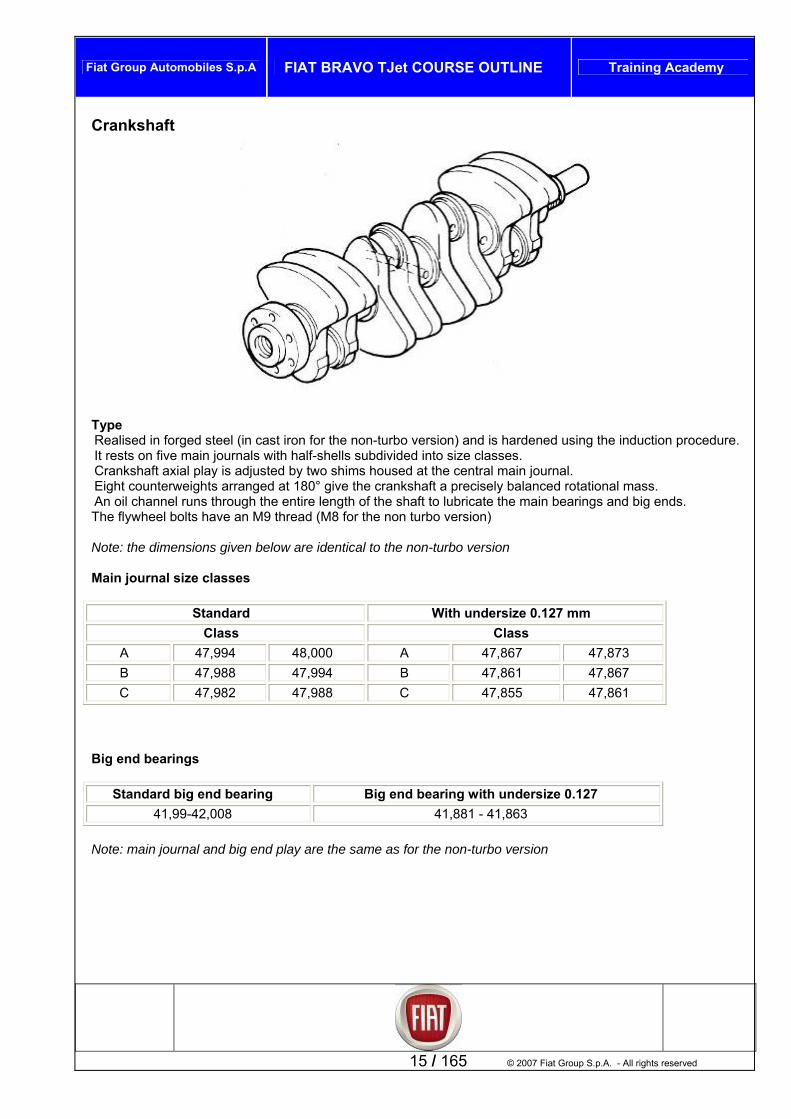
TypeRea d in forge n cast ir e non-turb n) and ened usin uction procedure.
rnals with half-shells subdivided into size classes. nkshaft axial play is adjusted by two shims housed at the central main journal.
rweights arranged at 180° give the crankshaft a precisely balanced rotational mass. through the entire length of the shaft to lubricate the main bearings and big ends. ave an M9 thread (M8 for the non turbo version)
No w are identica
ain journal size classes
Standard With undersize 0.127 mm
lise d steel (i on for th o versio is hard g the ind
It rests on five main jouCraEight counteAn oil channel runshe flywheel bolts hT
te: the dimensions given belo l to the non-turbo version
M
15 / 165 © 2007 Fiat Group S.p.A. - All rights reserved
Class Class A 47,994 48,000 A 47,867 47,873 B 47,988 47,994 B 47,861 47,867 C 47,982 47,988 C 47,855 47,861
Big end bearings
Standard big end bearing Big end bearing with undersize 0.127 41,99-42,008 41,881 - 41,863
Note: main journal and big end play are the same as for the non-turbo version

Fiat Group Automobiles S.p.A FIAT BRAVO TJet COURSE OUTLINE Training Academy
Flywheel
Type The flywheel is a dual torsional mass type (Dual Mass Flywheel or DVA). This type of flywheel is used in order to better uniform the motion of the crankshaft, and to prevent transmission of excessive vibration to the gearbox primary shaft, thereby reducing the noise generated by the motion of the gearbox cogs. The flywheel consists of:
A primary flywheel in steel Primary flywheel cover in steel, Secondary flywheel in cast iron in the area of the clutch disk resting plane Differential load spring inside flywheel lined with specific grease
The primary flywheel has a toothed crown that engages with the starter motor pinion. .
© 2007 Fiat Group S.p.A. – All rights reserved 16 / 165

Fiat Group Automobiles S.p.A FIAT BRAVO TJet COURSE OUTLINE Training Academy
Valve train
1. Camshaft oil seal 2. Camshaft 3. Tappet 4. Upper cap 5. Spring
6. Lower cap
Type Two overhead cams, in nodular cast iron, housed in an upper heThe shaft has suitably oriented and profiled cams, as many as theThe cam rise and timing angles are different for the two versioTo the front, the exhaust shaft is fitted with a toothed pulley via whi oned toothed belt connected to the crankshaft. A pair of gears mounted to the front of the shafts, trans shaft.
he material is
7. Cotters 8. Oil seal 9. Valve guide 10. Valve
ad unit, driven by belt and gear. re are valves to be operated.
ns, 120 HP and 150 HP ch it is driven by a suitably tensi
fers drive from the exhaust shaft to the intake
17 / 165 © 2007 Fiat Group S.p.A. - All rights reserved
Note: the exhaust valves for the 150 HP version are different from the aspirated version (tifferent), while the intake valves are identical. d
120 HP intake/exhaust camshaft
Intake cam Exhaust cam
tre) with a ontrol rise of 0.45 mm
Valve train diagram
iagram for the 120 HP version envisages: The valve train dIntake shaft ntake valve opening 2° after TDC (Top Dead Centre) and closing 27° after BDC (bottom dead cenI
c

Fiat Group Automobiles S.p.A FIAT BRAVO TJet COURSE OUTLINE Training Academy
© 2007 Fiat Group S.p.A. – All rights reserved 18 / 165
Exhaust shaft Exhaust valve opening 17° before BDC and closing 2° before TDC with a control rise of 0.45 mm 150 HP intake/exhaust camshaft
Intake cam Exhaust cam Valve train diagram The valve train diagram for the 150 HP version envisages: Intake shaft Intake valve opening 2° after TDC and closing 34° after BDC with a control rise of 0.45 mm Exhaust shaft Exhaust valve opening 27° before BDC and closing 2° before TDC with a control rise of 0.45 mm Note: the angular values between timing marks and the apex of the cam are values that allow for precise determination of correct timing, from a constructional point of view. In this publication they only serve to show the difference in timing between the 120 HP version and the 150 HP version

Fiat Group Automobiles S.p.A FIAT BRAVO TJet COURSE OUTLINE Training Academy
Hydraulic tappets The hydraulic tappets used on this engine automatically compensate any valve play while the engine is running, with the advantage of reducing:
Maintenance intervals Engine noise.
Opening phase When the camshaft presses on the cup (1) and as a result on the piston (2), the oil trapped in the chamber (6), by closure of the ball valve (4), transmits the motion of the piston (2) directly to the sleeve (3) and as a result to the valve. In this phase, given the high pressure to which it is subjected, a part of the oil in the chamber (6) seeps through the minimal clearance between the piston (2) and the sleeve (3).
Closing phase As the valve closes, for the tappet (pushed by the force of the spring (5) follows the profile of the cam and a vacuum is created inside the chamber (6) that causes the ball valve (4) to open, allow oil to enter. The oil entering the chamber (6) replaces the oil pushed out during the valve opening phase.
19 / 165 © 2007 Fiat Group S.p.A. - All rights reserved

Fiat Group Automobiles S.p.A FIAT BRAVO TJet COURSE OUTLINE Training Academy
© 2007 Fiat Group S.p.A. – All rights reserved 20 / 165
Auxiliaries drive belt Version with air-conditioner The alternator and air-conditioner compressor are driven by a Poly-V type drive belt. The belt is tightened by an automatic tightener, which is maintenance free. 1. Drive belt on engine 2. Alternator 3. Air-conditioner compressor 4. Automatic tightener 5. Crankshaft pulley Note: the Turbo version has an axially smaller compressor pulley, and tightener loading has been increased Versions without air-conditioner Poly-V driving alternator, tightening by alternator upper fasteners with adjuster slits
1. Alternator drive belt 2. Alternator 3. Crankshaft pulley 4. Alternator upper fasteners – belt tightener.

Fiat Group Automobiles S.p.A FIAT BRAVO TJet COURSE OUTLINE Training Academy
Circuits/systems Introduction This chapter describes the features of the following systems:
Intake, Exhaust, Fuel supply Crankcase gas/vapour recirculation, Evaporation control, Engine oil lubricating circuit, Engine cooling circuit
Air intake circuit (turbocompressor)
The air intake circuit consists of: 1. Dynamic air intake 2. Air filter 3. Turbocompressor 4. Intercooler 5. Intake manifold A pipe to the air filter leads from the dynamic intake in the upper zone of the front crossbar.
21 / 165 © 2007 Fiat Group S.p.A. - All rights reserved
1
2
3
5
4

Fiat Group Automobiles S.p.A FIAT BRAVO TJet COURSE OUTLINE Training Academy
After filtering, the air is drawn into the turbocompressor through a pipe, on which converge other pipes from: The dump valve system The gas recirculation system from crankcase The anti-evaporation system
The air compressed and heated by the turbocompressor passes to the intercooler where it exchanges heat with the outside air and cools. Then the compressed and cooled air is delivered to the throttle through a rigid pipe and then on to the intake manifold. The connector pipe between intercooler and manifold has a bellows type joint that offers a degree of installation flexibility, as well as vibration absorption with turbo running. A turbo pressure sensor is installed on the intercooler-throttle connector pipe, which also has a connection for the dump valve. The intake manifold also carries
The motorised throttle, The intake air pressure/temperature sensor, The injector rail and injectors
The pipes from: The crankshaft gas recirculation system The antievaporation system.
© 2007 Fiat Group S.p.A. – All rights reserved 22 / 165
The fuel supply system differential pressure regulator is also connected to the intake manifold by a rubber tube Turbocompressor
Type IHI RFH3 turbocompressor with waste gate entirely managed by the Engine Control Hub via turbo pressure solenoid valve. Specifications The turbocompressor is specific to the 120HP and 150HP versions. The substantial difference between the two groups are the different characteristics of the internal impeller, which determines the turbocharge logic. The impeller of the 150HP version gives maximum peak pressure at high torque values, emphasising engine “torque and power” performance. For Turbocompressor sport mode, a further pressure increase is foreseen, to create a significant “overboost” effect.

Fiat Group Automobiles S.p.A FIAT BRAVO TJet COURSE OUTLINE Training Academy
23 / 165 © 2007 Fiat Group S.p.A. - All rights reserved
On the contrary, the 120HP impeller offers improved performance at low engine speeds, to render driveability more pleasant, without excessive increase in fuel consumption. The turbocompressor is directly connected to the oil filter (green filter) from which it receives lubrication for the impeller shaft in addition to cooling. The oil is drained through a pipe attached to the oil filter, that connects the turbocompressor to the lower crankshaft and so to the oil sump. The turbocompressor is connected to the engine cooling circuit by a feed pipe from the radiator return and a drain pipe connected to the recirculation pipe from the thermostat to the reservoir/expansion chamber. Coolant is circulated naturally, not forced. The connection to the cooling circuit serves to prevent the abrupt temperature shifts produced when the engine is switched off, and that may cause burnt oil deposits on the turbine shaft, and consequent damage. This temperature shift could result in oxidization of the lubricating oil on the turbine shaft with consequent carbon deposits that could damage the turbine mechanics. Note: the seal between the turbocompressor and exhaust manifold must be replaced if the turbocompressor is dismantled, and the securing studs checked. Turbo pressure regulator valve
The turbo regulator electrovalve is controlled by the Engine Control Hub, and is connected as follows.
A high pressure socket downstream of the turbo impeller, A connection to the waste gate actuator A connection to the intake pipe upstream of the turbo impeller.

Fiat Group Automobiles S.p.A FIAT BRAVO TJet COURSE OUTLINE Training Academy
Shut-off or DUMP valve
The dump valve is electrically controlled by the Engine Control Hub. It is connected to the intake pipe near to the throttle body, and, through a pipe incorporated in the soundproofed engine cover upstream of the turbocompressor, the dump valve discharges excess pressure on throttle release, to prevent excessive pressure increases (ramming) that could damage the intake pipes and interfere with turbine function. 150 HP version turbocompressor specifications The graph gives the turbo pressure curves without overboost (curve A) and with overboost (curve B).
© 2007 Fiat Group S.p.A. – All rights reserved 24 / 165
A
B
Pres
sure
(mm
bar)
Engine Revs (RPM)

Fiat Group Automobiles S.p.A FIAT BRAVO TJet COURSE OUTLINE Training Academy
Test 1064 BA – Turbo pressure check Fit the turbo pressure sensor to tool N° 1871003500 and fasten it with the corresponding screw. Connect the electrical connection to the turbo pressure sensor. Connect tool EX09 from box N° 1806338000 to tool N° 1871003500 and connect connector N° 2000017500 (as shown in fig. 1) Fig. 1 Connect 5 bar pressure transducer EX06 to the tool and connect it to the Examiner Sam card with cable EX01. Place the Examiner in the passenger compartment and make the connections. Select “pressure gauge” on the examiner and set for “intake pressure” data acquisition with end scale 2000 mmHg and time selection 10 seconds. Take the vehicle out onto the road (observing speed limits set by the highway code) and carry out the following test. On a country road with 3rd gear engaged. Begin graph acquisition pressing “start” on the diagnosis instrument and after 5 seconds press full down on the accelerator until reaching 4500 rpm. On reaching this speed, fully release the accelerator pedal. Display the resulting graph, read off the maximum peak value between 1900 and 2000 mbar (1444 and 1520 mmHg) corresponding to a turbo pressure of between 900 and 1000 mbar. Disconnect Examiner and pressure transducer. Disconnect the turbo sensor connection. Unscrew and remove the pressure sensor from the tool. Remove the turbo pressure check tool. Refit the turbo pressure sensor.
25 / 165 © 2007 Fiat Group S.p.A. - All rights reserved
1

Fiat Group Automobiles S.p.A FIAT BRAVO TJet COURSE OUTLINE Training Academy
Graph of turbo maximum peak pressure Test 1064BG Waste Gate valve actuator correct stroke check for 150 HP version
STEP CHECK SOLUTION IF CHECK NOT OK
1
With engine cold, check the calibration of overpressure valve under the following operating conditions: -Remove the soundproofing cover on the engine. -Remove the heat guard cover on the turbine.
nnect tube (1) connecting valve with turbo ressure regulation solenoid.
-Install tool N° 2000024800 (3) on waste gate rod -Apply a dial gauge so it touches the end of the tool.
Replace turbocompressor
© 2007 Fiat Group S.p.A. – All rights reserved 26 / 165
-Discooverp
-Zero the dial gauge -Connect the vacuum pump n.° 2000015500 (2) to the overpressure valve
h the pump and -Introduce a pressure of 0.74±0.03 bar witcheck on the dial gauge that the rod moves 2.00±0.5 mm.

Fiat Group Automobiles S.p.A FIAT BRAVO TJet COURSE OUTLINE Training Academy
Exhaust pipes
27 / 165 © 2007 Fiat Group S.p.A. - All rights reserved
Engine exhaust gases are conveyed to the manifold-three-way catalytic converter assembly, via exhaust manifold 4,2,1, with the turbocompressor inserted between the exhaust manifold and the catalytic converter. The front part of the exhaust pipe consists of a vibration reducing flexible element and a silencer. The rear section of the exhaust has a terminal muffler. The upper part of the exhaust is suitably heat-shielded to prevent heat transfer to the body shell. The various components are mounted on brackets and flexible rings fastened to the body shell.

Fiat Group Automobiles S.p.A FIAT BRAVO TJet COURSE OUTLINE Training Academy
Exhaust manifold
The exhaust manifold is branched into ducts forming a 4-2-1 configuration. As can be seen in the figure, the ducts of the first and fourth cylinder combine with those of the second and third on the turbocompressor connector flange, so they are separated.
his solution prevents the various gas flows from interfering with each other, improving performance and fuel
exhaust manifold. CT t gases present in exhaust emissions:
Unburned hydrocarbons (HC); Carbon monoxide (CO);
). n take place in the catalytic converter:
of the CO and HC, converted into carbon dioxide (CO2) and water (H2O); rted into Nitrogen (N2).
T c f a block, a metal mesh support for dampening impact and vibration and an outer shell h g nce, corrosion-proof stainless steel.
lls in the core at temperatures in excess of 300 ° - 350 °C,
Tconsumption and reducing pollutant emissions. N :ote the second and third cylinder ducts come together inside the
atalytic converter simultaneously scrubs the three he hree-way catalytic converter
Nitrogen oxide (NOxT owo types of chemical reacti
Oxidation Reduction of the Nox, conve
he onverter consists oi h temperature resistain
© 2007 Fiat Group S.p.A. – All rights reserved 28 / 165
The block consists of a honeycomb structure made up of a ceramic material lined with a film of active catalytic substances, platinum and rhodium, which accelerate the chemical decomposition of the toxic substances contained in exhaust gases which, through the ceactivate the catalysers and thus the oxidation reduction reactions. To optimise the efficiency and lifespan of the catalytic converter, a perforated sheet metal cone is fitted to improve gas diffusion in the cells of the ceramic core.

Fiat Group Automobiles S.p.A FIAT BRAVO TJet COURSE OUTLINE Training Academy
29 / 165 © 2007 Fiat Group S.p.A. - All rights reserved
1. Ceramic honeycomb block 2. Metallic support 3. Outer shell 4. Perforated sheet metal cone Note: Due to the high temperatures present, the precious metals contained in the catalytic converter are highly susceptible to chemical attack by any lead present in exhaust gases. Using fuel containing lead will result in rapid and irreversible damage to the converter. For this reason, fuel containing lead must never be used, even if in case of emergency or for an extremely short time.

Fiat Group Automobiles S.p.A FIAT BRAVO TJet COURSE OUTLINE Training Academy
Fuel supply system
The fuel supply system serves to supply fuel at the correct working pressure to the injector group. The system consists of:
he pump group consists of: An electric fuel pump; Fuel filter;
re regulator; Fuel level sensor.
The b via a specific power relay. An inertia switch is installed betwee terminal of the fuel pump and the chassis ground, which open in case of collision, to preThe up and is maintenance-free. The pressure regulator on the pump delivery pipe, which assures safe
rculation of the fuel if the maximum pressure of 6.9 – 9.8 Bar is exceeded. he pump group also includes the fuel level sensor, connected directly to the Body Computer Hub
ote: Fuel level information is transmitted from the Engine Control Hub to the Body Computer Hub via C-CAN etwork.
rn pipe connects the tank to the injector rail. The pipe is connected by quick-fit connectors. ctor rail supplies fuel to the injectors, is realised in metal and has:
An inlet, connected to the delivery pipe, An outlet connected to the recirculation pipe.
The Rail incorporates a differential pressure regulator mounted in a specific housing located at the connection with the recirculation pipe. The regulator is in turn connected by rubber pipes to the intake manifold.
A fuel level indicator/pump group immersed in the fuel tank; A delivery pipe;
An injector rail with built-in differential pressure regulator; A recirculation pipe.
T
Maximum pressu
fuel pump is controlled by the Engine Control Hun the negative
vent possible fire hazard due to leaking fuel. fuel filter is inserted in the pump gro
© 2007 Fiat Group S.p.A. – All rights reserved 30 / 165
pump group includes a maximumreciT Nn The fuel retuThe inje
Fiat Group Automobiles S.p.A FIAT BRAVO TJet COURSE OUTLINE Training Academy
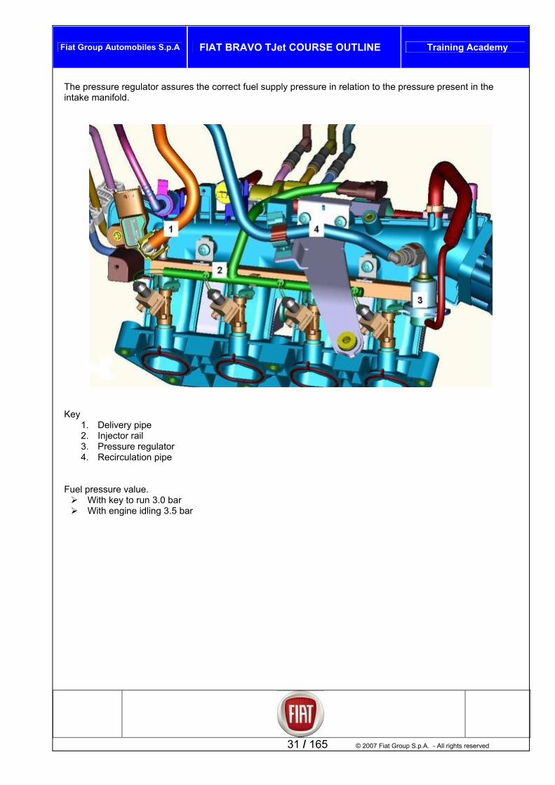
The pressure regulator assures thtake manifold.
e correct fuel supply pressure in relation to the pressure present in the
in
Key
1. Delivery pipe 2. Injector rail 3. Pressure regulator 4. Recirculation pipe
F uel pressure value.
With key to run 3.0 bar With engine idling 3.5
31 / 165 © 2007 Fiat Group S.p.A. - All rights reserved
bar

Fiat Group Automobiles S.p.A FIAT BRAVO TJet COURSE OUTLINE Training Academy
© 2007 Fiat Group S.p.A. – All rights reserved 32 / 165
r/gas recirculation system
he system decants and burns breather gases from the crankcase. These gases consist of mixtures of air, el vapours and burnt bases seeping through the piston rings, as well as lubricating oil vapour. he vented gas from the crankcase rises up to the cylinder head and is conveyed into a separator (1) with a embrane that permits:
vapour condensation and recovery vapour absorption into the intake circuit for combustion.
pecifically, the system has two vapour intake pipes, one connected to the intake manifold (2) and the other onnected upstream of the turbocompressor (3), which permit:
With turbo operating, gas delivery through a duct connected immediately upstream of the compressor. When idling or on release through a duct connected downstream of the throttle.
2. Connection to intake pipe upstream of turbo compressor
3. Passage switching membrane 4. Oil vapour condensation cones 5. Oil vapour recovery on head
Crankcase vapou
TfuTm
Sc
System cross-section
1. Connection to intake manifold
3
1
2

Fiat Group Automobiles S.p.A FIAT BRAVO TJet COURSE OUTLINE Training Academy
Anti-evaporation system
he anti-evaporation system serves to prevent fuel vapour, made up of the lighter fractions of hydrocarbons at mainly form in the fuel tank, from escaping into the atmosphere. he system consists of:
Fuel tank, Vapour separator,
stem works most with high external temperature , meaning when the temperature of fuel in the tank creases, with consequent tendency toward increased evaporation. his situation causes an increase in pressure inside the tank. he two float valves on the tank and directly connected to the canister. he fuel vapour reach the carbon filter through a calibrated hole in a valve located inside the vapour eparator/filter group. he same calibrated hole permits entry of air into the tank through the carbon filter, as necessary as the fuel vel drops. he CANISTER active carbon filter is connected by a pipe to the purification e-valve, which when activated by
the Engine Control Hub in certain conditions, permits intake of vapour from the engine consequently cleaning the filter. If due to malfunction, fuel tank internal pressure should reach dangerously high levels, the safety valve on the filler caps allows this pressure to discharge. If necessary, this valve may open in the other direction to prevent formation of vacuum inside the fuel tank.
33 / 165 © 2007 Fiat Group S.p.A. - All rights reserved
TthT
Float valve, Two-way fuel filler cap vent valve, CANISTER active carbon filter Active carbon filter cleaning valve, Safety check-valve.
The syin
s
TTTsTleT

Fiat Group Automobiles S.p.A FIAT BRAVO TJet COURSE OUTLINE Training Academy
Active carbon filter
The active carbon filter is located under the rear right wheelarch and has two intakes, from the vent valvand a pipe to deliver
es, y vapour to the filter cleaning e-valve.
Filter The valve (A) is located on the intake manifolds to the lower side, and is therefore not visible. The valve is connected to a pipe that forks to one side to the intake manifold downstream of the throttle, and to the other side to a connector upstream of the turbocompressor on the intake pipe. This connection configuration allows fuel vapour to be drawn off whether idling or with engine under turbo power. The recirculation pipes have safety check-valves (B and C).
© 2007 Fiat Group S.p.A. – All rights reserved 34 / 165
cleaning e-valve

Fiat Group Automobiles S.p.A FIAT BRAVO TJet COURSE OUTLINE Training Academy
35 / 165 © 2007 Fiat Group S.p.A. - All rights reserved
Float valve hese valves are used for the followinT g functions:
To prevent liquid fuel escaping in the event of an accident with vehicle overturned; To allow fuel vapour to vent from the tank to the separator and active carbon filter; To permit tank ventilation in case of internal vacuum formation.
his valve consists of a body (1) and float/valve (2). marised in the following cases, in relation to the amount of fuel in the
the hole (3) preventing liquid fuel from
Intermediate fuel level If the fuel level in the tank is low, the float (2) drops, opening the passage (3). This allows fuel vapour to exit the tank and reach the separator and active carbon filter, or through the same circuit, ventilate the tank if tank internal pressure is lower than external pressure.
Seal in case of roll-over If the vehicle rolls over, however full the tank is, the float (2) closes the hole (3) with its own weight plus that of the fuel, preventing a hazardous flow of fuel to the vapour separator and consequent fire risk.
TThe function of the valve can be sumtank. Tank full/vehicle inclined If the tank is full the float (2) blocks reaching the separator.
Fiat Group Automobiles S.p.A FIAT BRAVO TJet COURSE OUTLINE Training Academy
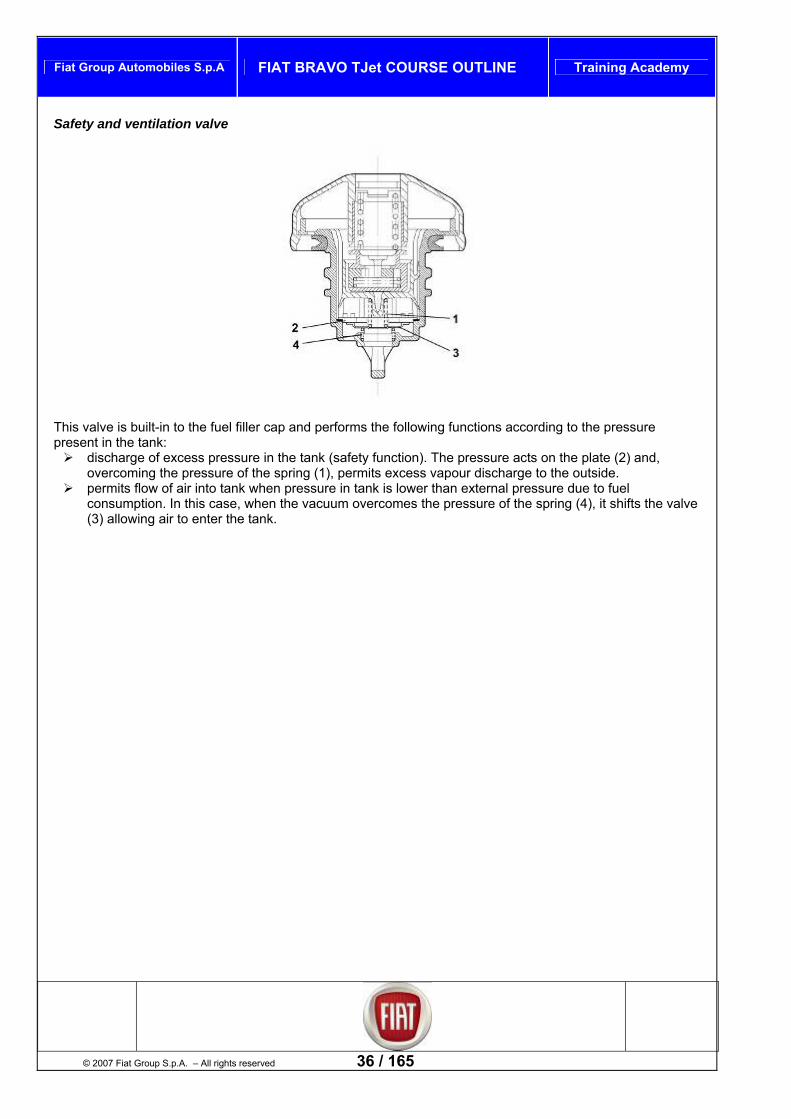
Safety and ventilation valve
© 2007 Fiat Group S.p.A. – All rights reserved 36 / 165
This valve is built-in to the fuel filler cap and performs the following functions according to the pressure resent in the tank:
discharge of excess pressure in the tank (safety function). The pressure acts on the plate (2) and, overcoming the pressure of the spring (1), permits excess vapour discharge to the outside.
permits flow of air into tank when pressure in tank is lower than external pressure due to fuel consumption. In this case, when the vacuum overcomes the pressure of the spring (4), it shifts the valve (3) allowing air to enter the tank.
p
Fiat Group Automobiles S.p.A FIAT BRAVO TJet COURSE OUTLINE Training Academy
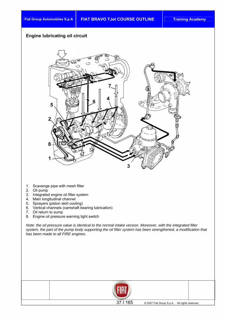
Engine lubricating oil circuit
1. Scavenge pipe with mesh filter 2. Oil pump 3. Integrated engine oil filter system 4. Main longitudinal channel 5. Sprayers (piston skirt cooling) 6. Vertical channels (camshaft bearing lubrication) 7. Oil return to sump 8. Engine oil pressure warning light switch Note: the oil pressure value is identical to the normal intake version. Moreover, with the integrated filter system, the part of the pump body supporting the oil filter system has been strengthened, a modification that
een made to all FIRE engines.
37 / 165 © 2007 Fiat Group S.p.A. - All rights reserved
has b

Fiat Group Automobiles S.p.A FIAT BRAVO TJet COURSE OUTLINE Training Academy
Integrated engine oil filter system
Key: A. turbocompressor lubrication circuit B. modine heat exchanger cooling circuit The lubrication system has an integrated filter system called Green Filter. The device is mounted on the engine oil filter cartridge. The system consists of:
A cup containing the high filtration capacity engine oil filter cartridge, closed by a plastic plug. A modine type heat exchanger.
The oil flows from the pump to the oil filter system, to remove any impurities that could be extremely damaging above all to the turbocompressor, and is delivered to the engine. Note: The oil pressure switch is mounted on the pump oil filter support, as in the non-turbo versions.
© 2007 Fiat Group S.p.A. – All rights reserved 38 / 165
A
B
Fiat Group Automobiles S.p.A FIAT BRAVO TJet COURSE OUTLINE Training Academy
The oil filter system has the corom the turbocompressor the oil flows t
nnector for the oil delivery pipe to the turbocompressor. hrough specific pipes that connect to the crankcase and then to the
ote: since the turbocompressor is positioned very high on the engine, the oil drain pipe is fastened in an tem, in order to assure its mechanical integrity.
For o m there the coolant reaches the Modine type heat hrough, returns to the main recirculation pipes Note: ed with copper gaskets that must be repla Engi
he e created by the rotation of the gears fitted to the
.3 the pressure exerted by the limiter valve (5) overcomes ning the connection between the pressure
chamb el in the circuit.
Fsump. Nintermediate position on the oil filter sys
il cooling, a pipe connects directly to the thermostat, and froo the oil filter system, and after passing texchanger built-in t
o thr ugh a specific tube.
the pipe unions of the integrated engine oil filter system are fittced whenever the pipes are removed.
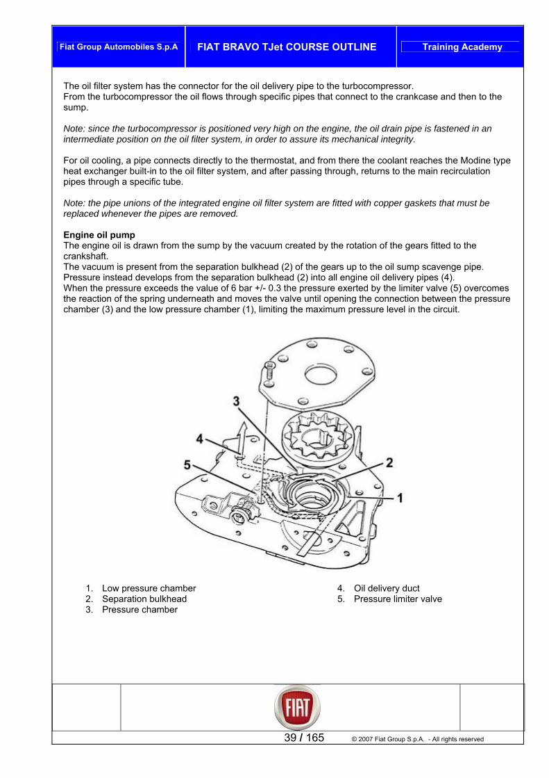
ne oil pump ngine oil is drawn from the sump by the vacuumT
crankshaft. The vacuum is present from the separation bulkhead (2) of the gears up to the oil sump scavenge pipe. Pressure instead develops from the separation bulkhead (2) into all engine oil delivery pipes (4). When the pressure exceeds the value of 6 bar +/- 0the reaction of the spring underneath and moves the valve until ope
er (3) and the low pressure chamber (1), limiting the maximum pressure lev
39 / 165 © 2007 Fiat Group S.p.A. - All rights reserved
1. Low pressure chamber 2. Separation bulkhead 3. Pressure chamber
4. Oil delivery duct 5. Pressure limiter valve

Fiat Group Automobiles S.p.A FIAT BRAVO TJet COURSE OUTLINE Training Academy
Eng closed position ine oil pressure limiter valve
© 2007 Fiat Group S.p.A. – All rights reserved 40 / 165
Engine oil pressure limiter valve short-circuit position

Fiat Group Automobiles S.p.A FIAT BRAVO TJet COURSE OUTLINE Training Academy
Engine cooling circuit
41 / 165 © 2007 Fiat Group S.p.A. - All rights reserved
The engine cooling circ Coolant pum
uit consists of: p
Fluid passages in engine (optimised for turbo version) Thermostat, Piping to connect with radiator for vehicle interior heating Piping to connect with engine cooling radiator Piping to connect with heat exchanger on oil filter system Piping to connect with turbocompressor Recirculation piping to pump. Reservoir/expansion chamber
Reservoir/expansion chamber The reservoir/expansion chamber feeds the circuit and absorbs the variations in coolant fluid volume, as engine temperature varies. A calibrated valve, in the pressurised cap, permits:
Exit of air from circuit collected in pipe from thermostat Entry of air when circuit is under low pressure (due to engine cooling).
Radiator The radiator is a radiant mass with two lateral chambers for coolant intake and output. The pipes and fins of the radiator are aluminium, the tanks plastic.

Fiat Group Automobiles S.p.A FIAT BRAVO TJet COURSE OUTLINE Training Academy
Water pump Blade type centrifugal fastened to the crankcase and driven directly by the valve train drive belt. Note the pump impeller is larger than the normal intake version. Thermostat
Mounted on the rear side of the cylinder head, serves to maintain engine at optimal temperature:
with temperature > 80 ± 2°C the thermostat (open) conveys coolant to the radiator. ostat has a coolant temperature sensor (5) connected to the Engine Control Hub, in addition to the
ections to the cooling system pipes:
2. to vehicle interior heater
g system
g to specific functional logic.
ned
with temperature < 80 ± 2°C the thermostat (closed) switches coolant toward the pump
The thermvarious conn
1. to engine cooling radiator
3. to Modine heat exchanger on oil filter group 4. to reservoir/expansion chamber
Electric fan The two-speed cooling fan increases the heat dissipation capacity of the radiator and/or conditionincondenser. It is directly controlled by the Engine Control Hub accordin
N : version fan is two-speed, both for the air-condtioand for the heated version.
ote as opposed to the normal intake version, the turbo
© 2007 Fiat Group S.p.A. – All rights reserved 42 / 165

Fiat Group Automobiles S.p.A FIAT BRAVO TJet COURSE OUTLINE Training Academy
Electrical components Introduction This chapter illustrates the features of the electrical components (sensors /actuators) of the engine cosystem.
ntrol
diagram ngine control unit.
Engine Control Hub input/output informationT fohe llowing diagram shows the information input to and output from the e
43 / 165 © 2007 Fiat Group S.p.A. - All rights reserved
1. Engine control unit 2. Battery 3. Ignition switch 4. Engine control system relay
5. Fuel pump relay 6. Fuel pump 7. Radiator fan relay/s 8. Radiator fan

Fiat Group Automobiles S.p.A FIAT BRAVO TJet COURSE OUTLINE Training Academy
9. Compressor enable relay 0. Compressor
11. Ignition coil 2. Spark plugs
r
nsor
n to C-CAN ontrol unit (via
26. Diagnosis tool connection (via CAN network) 27. Rev counter (via CAN network) 28. System fault warning light (direct line) 29. Tachometer (via CAN network) and ABS control
unit ia CAN
31. Turbo pressure sensor 32. Turbo waste gate pressure valve 33. 34. 35. stop light switch 36. 37. 38. 39. network)
Engi
1
113. Electroinjectors 14. Carbon filter cleaning solenoid
5. Lambda probe (pre-catalyser) 30. City/sport button for power steering (v
network) 116. Lambda probe (post-catalyser) 7. Coolant temperature senso1
18. Pinging sensor 19. Throttle control actuator and throttle
position sensor 20. Engine speed and TDC sensor 21. Injection phase sensor
te pressure se22. Air temperature/absolu23. Oil pressure switch 24. Body computer (connectio
network)25. CODE cCAN network)
ne Control Hub
Shut-off valve (DUMP) Accelerator pedal sensor Brake pedalClutch pedal switch Line pressure sensor Cruise control lever Vehicle speed signal (via CAN
d throttle, based on c tegrated e
ry, reprogrammable from the outside without intervening on the
placed, the throttle position self-teaching procedure must be pea
ected syste
apable of w
Type Bosch Motronic ME 7.9.10 A1 motorise ontrol of engine torque demanded by d
ction/ignition systems. river.
This belongs to the category of sequential timed inThe control unit has a flash EPROM memo
lectronic inje
hardware. If the injection control unit or throttle body are re
ted. re
unction FThe system serves to control the engine and conn ms Location The control unit is mounted in engine bay and is c
© 2007 Fiat Group S.p.A. – All rights reserved 44 / 165
ithstanding high temperatures.

Fiat Group Automobiles S.p.A FIAT BRAVO TJet COURSE OUTLINE Training Academy
Specifications and function ensors, the Engine Control Hub (or ECH) regulates the quantity of air/fuel and the ignition
n as engine ronmental conditions vary. ctors spra
The ignition system is static type with coil for the spark plugs, odules contained in the ECH ough:
A nsor located on the intake duct ator.
Through a probe upstream of the converter the ECH combustion is within optimal
The EC and so is able to recognise the ch pensate th at idle sp h engine loading.
The sys EOBD standards and so is able ctional y malfunc gh Mil
The fue s a return circuit and mechanical l pump is
Through controls activation of the engin pressor
onnected to the C-CAN communications networhts, the co ect.
ceived and transmitted over C-CAN network nsmits and receives a series of messages over sed ry out functions in synergy with other hubs (for example, transmission/reception of data for ESP ansmission of information on engine temperatur table gives the most significant messages defined as st to basic enerally these also contain any error state indic
ansmitted over C-CAN network ts for ECH unlock code (IMMO code) for the COrevs state oil minimum pressure state temperature state over temperature state edal state
C or display on instrument panel mpressor pressure state
nsumption state n compressor on state
smission control.
Messages received from C-CAN network ECH unlock code for CODE function Key to ON state on network Vehicle speed state Brake Hub parameter state for ESP/ASR control Robotic transmission hub parameter states Sport button pressed state from Power Steering Hub Alternator state Fuel level state
Through its sadvance, in order to permit correct engine functio load and enviThe fuel injection system is indirect type, so the inje y the fuel behind the intake valves.
and power mThe ECH controls and regulates turbo pressure thr
turbo pressure se An electrovalve acting on the waste-gate actu
the lambd verifies that values.
H is self-adapting, anges taking place in the engine and comfor them according to “self-adapting” functions, bo
tem complies witheed and under higto detect the presence of misfires, the fun
integrity of the catalytic converter and to indicate an tions in the exhaust emissions system throuwarning lights.
l supply system ha differential pressure regulator. The fuecontrolled by the ECH.
relays, the ECH e cooling fan and air-conditioning comactivation. The ECH is c k, of which it is a terminal. For activation of the MIL engine control warning lig nnection is dir Messages reThe ECH tra the C-CAN network. These messages are umainly to carfunction, or tr e to the Instrument Panel Hub).
ates, since in addition The followinginformation, g ations. Messages tr
Reques DE function. Engine Engine Engine Engine Brake p Clutch pedal state
ruise control state f Turboco Fuel co Conditio ESP/ASR control parameter state Engine parameter states for robotic tran
45 / 165 © 2007 Fiat Group S.p.A. - All rights reserved

Fiat Group Automobiles S.p.A FIAT BRAVO TJet COURSE OUTLINE Training Academy
Electrical co
nnections
Engine Control Hub PiN
n out ote: all pins are listed, including any not effectively used, or not used for Fiat Bravo applications.
60-pin engine side connector
P
PPin 3 Control (-) canister electrovalve Pin 4 Control (-) cylinder 2 injector Pin 5 Control (-) dump valve Pin 6 CNG injector not used Pin 7 CNG injector not used Pin 8 CNG injector not used Pin 9 Turbo pressure and air
temperature/pressure sensor 5V power supply
Pin 10 Motorised throttle potentiometer 5V power supply
Pin 11 Timing sensor 5V power supply Pin 12 Timing sensor signal Pin 13 Motorised throttle potentiometer ground
reference P il temperature reference ground
PP
PPPPin 20
Pin 23 N.C. Pin 24 Intake air temperature Pin 25 Intake air pressure signal Pin 26 N.C. Pin 27 oil level switch not used Pin 28 Timing sensor ground reference Pin 29 Engine temperature sensor ground
reference Pin 30 Exhaust gas temperature sensor ground
not used Pin 31 Cylinder 1 ignition coil command Pin 32 CNG rail temperature sensor signal not
used Pin 33 Exhaust gas temperature signal not used Pin 34 Engine oil temperature signal not used Pin 35 Engine oil pressure switch Pin 36 Pinging sensor ground Pin 37 Revs sensor (-) Pin 38 Revs sensor (+)
signal
in 1 Control (-) Lambda probe heater
downstream of catalyser in 2 Control (-) cylinder 3 injector
Pin 21 Turbo pressure sensor signal Pin 22 Motorised throttle potentiometer TPS2
signal
in 14 Engine onot used
in 15 Alternator terminal (D+) not used in 16 Control (-) Lambda probe heater
© 2007 Fiat Group S.p.A. – All rights reserved 46 / 165
downstream of catalyser in 17 Control (-) cylinder 1 injector in 18 Control (-) waste gate not used in 19 Control (-) cylinder 4 injector
CNG injector not used
Pin 39 N.C. Pin 40 N.C. Pin 41 N.C. Pin 42 Motorised throttle potentiometer “TPS1”

Fiat Group Automobiles S.p.A FIAT BRAVO TJet COURSE OUTLINE Training Academy
Pin 43 Engine temperature signal Pin 44 Turbo pressure and air temperature and
Pin 53 Reference ground Lambda probe downstrea
pressure sensor reference ground
Cylinder 4 ignition coil command l command
servo motor power supply (-) Pinging sensor signal
upstream of catalyser
m of catalyser Pin 54 Reference ground Lambda probe
downstream of catalyser Pin 55 Signal from Lambda probe upstream of
catalyser Pin 56 N.C.
Pin 58 CNG rail pressure sensor not used Pin 59 Oil condition sensor not used Pin 60 N.C.
4-pin vehicle side connector
Pin 1 Engine system ground on battery negative Pin 2 Engine system ground on battery negative Pin 3.Power supply positive 12V from F17 10A Pin 4.Engine system ground on battery negative Pin 5 Power supply positive 12v from F17 10A Pin 6 Power supply positive 12V from F16 7,5A Pin 7 Linear pressure sensor reference ground Pin 8 Starter control relay LSD not used Pin 9 N.C. Pin 10 N.C. Pin 11 Conditioner compressor relay command Pin 12 Engine cool. fan relay command (speed
2) Pin 13 Engine cool. fan relay command (speed 1
or single speed) Pin 14 Engine cool. fan relay command (speed 3
or PWM) Pin 19 Control (-) turbo pressure waste-gate
electrovalve Pin 27 Accelerator pedal potentiometer “POT 2”
5V power supply Pin 28 Linear pressure sensor 5V power supply Pin 29 Accelerator pedal potentiometer “POT 2”
reference ground Pin 30 Accelerator pedal potentiometer “POT 1”
reference ground Pin 31 Starter control relay HSD not used Pin 32 N.C. Pin 33 Alternator L terminal D + not used Pin 34 N.C. Pin 35 N.C. Pin 36 N.C. Pin 37 N.C. Pin 38 N.C. Pin 39 N.C. Pin 40 N.C. Pin 41 N.C. Pin 42 N.C. Pin 43 N.C. Pin 44 N.C. Pin 45 N.C.
Pin 46 N.C. Pin 47 N.C. Pin 48 N.C. Pin 49 Accelerator pedal potentiometer “POT 1”
5V power supply Pin 50 N.C. Pin 51 N.C. Pin 52 N.C. Pin 53 CAN protection ground not used Pin 54 CNG petrol selector switch not used Pin 55 Accelerator pedal potentiometer “POT 2”
potentiometer signal Pin 56 N.C. Pin 57 Linear pressure sensor signal Pin 58 N.C. Pin 59 G force sensor not used Pin 60 Vehicle speed sensor not used Pin 61 “Resume” signal from cruise control stick Pin 62 N.C. Pin 63 Clutch pedal switch signal Pin 64 Conditioner enable command Pin 65 N.C. Pin 66 CAN-L network (transit) not used Pin 67 CAN-H network (transit) not used Pin 68 Fuel pump relay command Pin 70 Power supply positive F18 10A Pin 71 MIL warning light command Pin 72 Engine control system main relay
command Pin 73 CNG pressure valve (shut-off) not used Pin 74 N.C. Pin 75 CNG tank valve not used Pin 76 Accessories key switch not used Pin 77 CNG tank pressure sensor not used Pin 78 N.C. Pin 79 Accelerator pedal potentiometer “POT 1”
potentiometer signal Pin 80 Clutch potentiometer not used Pin 81 N.C. Pin 82 Stop light switch signal Pin 83 N.C.
Pin 45 N.C. Pin 46 Cylinder 3 ignition coil command Pin 47 Pin 48 Cylinder 2 ignition coiPin 49 Throttle servo motor power supply (+) Pin 50 Throttle
Pin 57 Alternator terminal F not used
Pin 51 Pin 52 Reference ground Lambda probe
47 / 165 © 2007 Fiat Group S.p.A. - All rights reserved
9

Fiat Group Automobiles S.p.A FIAT BRAVO TJet COURSE OUTLINE Training Academy
Pin 84 “+“ signal from cruise control stick rom cruise control stick
Pin 86 “-“ signal from cruise control stick Pin 87 Stop light switch signal Pin 88 CAN network terminal C-CAN-L Pin 89 CAN C-CAN-H network
Pin 90 Fiat Code W line not used Pin 91 K line Pin 92 N.C. Pin 93 N.C. Pin 94 Engine revs signal not used
© 2007 Fiat Group S.p.A. – All rights reserved 48 / 165
Pin 85 “ON/OFF“ signal f
Fiat Group Automobiles S.p.A FIAT BRAVO TJet COURSE OUTLINE Training Academy
Sensors Revs sensor
pe
c
ioned on e crankshaft pulley.
n
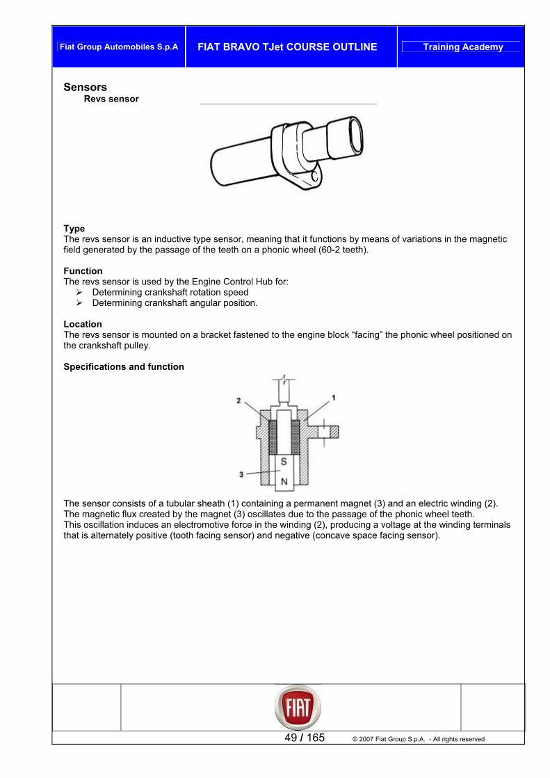
TyThe revs sensor is an inductive type sensor, meaning that it functions by means of variations in the magnetifield generated by the passage of the teeth on a phonic wheel (60-2 teeth). Function The revs sensor is used by the Engine Control Hub for:
Determining crankshaft rotation speed Determining crankshaft angular position.
Location The revs sensor is mounted on a bracket fastened to the engine block “facing” the phonic wheel positth Specifications and functio
The sensor consists of a tubular sheath (1) containing a permanent magnet (3) and an electric winding (2).
he magnetic flux created by the magnet (3) oscillates due to the passage of the phonic wheel teeth. scillation induces an electromotive force in the winding (2), producing a voltage at the winding terminals
that is alternately positive (tooth facing sensor) and negative (concave space facing sensor).
49 / 165 © 2007 Fiat Group S.p.A. - All rights reserved
TThis o
Fiat Group Automobiles S.p.A FIAT BRAVO TJet COURSE OUTLINE Training Academy
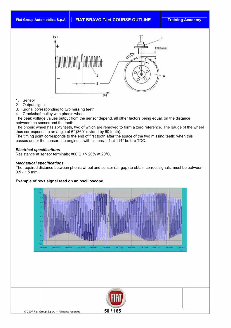
1. Sensor . Output signal
g teeth l
k voltage values output from the sensor depend, all other factors being equal, on the distance sensor and the tooth.
reference. The gauge of the wheel
point corresponds to the end of first tooth after the space of the two missing teeth: when this
sensor terminals; 860 Ω +/- 20% at 20°C.
btain correct signals, must be between
xample of revs signal read on an oscilloscope
23. Signal corresponding to two missin4. Crankshaft pulley with phonic wheeThe peabetween the The phonic wheel has sixty teeth, two of which are removed to form a zerohus corresponds to an angle of 6° (360° divided by 60 teeth). tThe timingpasses under the sensor, the engine is with pistons 1-4 at 114° before TDC. Electrical specifications Resistance at Mechanical specifications
he required distance between phonic wheel and sensor (air gap) to oT0.5 - 1.5 mm. E
© 2007 Fiat Group S.p.A. – All rights reserved 50 / 165

Fiat Group Automobiles S.p.A FIAT BRAVO TJet COURSE OUTLINE Training Academy
Electrical connections
Pin A Signal + Pin B Signal -
iming sensor T
ype he timing sensor is a Hall effect type sensor. A semiconductor wafer with current flowing through it
tic field generates a potential difference at the terminals, known as “Hall”
he timing sensor is used by the Engine Control Hub to recognise top dead centre of the cylinders in order to y hronise ignition timing and fuel injection
ion ing s located on the upper head in a specific housing, and faces onto the intake side camshaft.
TTimmersed in a normal magnevoltage. Function Ts nc LocatThe tim ensor is
51 / 165 © 2007 Fiat Group S.p.A. - All rights reserved

Fiat Group Automobiles S.p.A FIAT BRAVO TJet COURSE OUTLINE Training Academy
Specifications and function
A semiconductor wafer with current flowing through it immersed in a normal magnetic field (force lines perpendicular to direction of current) generates a potential difference at the terminals, known as “Hall” voltage. If the current intensity remains constant, the voltage generated only depends on the intensity of the magnetic field. It is thus sufficient that the magnetic field intensity varies periodically to obtain a modulated electrical signal, the frequency of which is proportional to the rate of change of the magnetic field. To obtain this variation, the distance between the sensor and the phonic wheel on the camshaft axis is varied,
g use of the valve timing mark. pulley rotates the distance varies and high tension signal is generated at the reference mark.
E tS
A a
makinAs the
lec rical specifications upply voltage 5V +/- 10%
Maximum voltage 16V Mechanical specifications
ir g p 1 +/- 0,5 mm F Example of timing signal read on an oscilloscope
astening screw tightening 8 +/- 1,6 Nm
© 2007 Fiat Group S.p.A. – All rights reserved 52 / 165
Note: the sensor is powered directly by the Engine Control Hub

Fiat Group Automobiles S.p.A FIAT BRAVO TJet COURSE OUTLINE Training Academy
Electrical connections
Pin 1 ground Pin 2 signal Pin 3 5 V power supply
Engine coolant temperature sensor
Type This is an NTC type sensor (Negative Temperature Coefficient). Function The engine coolant temperature sensor is used by the Engine Control Hub to calculate engine temperature. This information is obtained by exploiting the capacity of the sensor element to vary its resistance according to temperature. Location The engine temperature sensor is mounted on the thermostat group. Specifications and function
53 / 165 © 2007 Fiat Group S.p.A. - All rights reserved

Fiat Group Automobiles S.p.A FIAT BRAVO TJet COURSE OUTLINE Training Academy
Key 1. NTC resistor . Sensor body
cal r The reference olts. Since the Engine Control Hub input circuit is designed as a voltage splitte ided between a resistor present in the Engine Control Hub and the NTC r of the
s that f evaluating the variations in sensor resistance through the
lectrical specifications su
MaximumMaximum
rison table °C / Ω nominal
23. Electri connecto
voltage for the NTC unit is 5 Vr, this voltage is div
esistort follow
sensor. the Engine Control Hub is capable oI
changes in voltage, and thereby obtain temperature information. EPower pply 5 V
current 2,5 mA power at 25 °C 15 mW
CompaInternal resistance given is
°C Ω -40 48805 50 806.9-30 27414 60 575.8-20 15971 70 418.1 -10 8.6 9620 80 300 231.2 5975 90
10 175.7 3816 100 20 2502 110 135.225 2044 105.4 120 30 83.1 1679 130 40 1152 140 66.2
Mechanical specifications Tightening torque 22 Nm Electrical connections
© 2007 Fiat Group S.p.A. – All rights reserved 54 / 165
Pin 1 signal Pin 2 ground

Fiat Group Automobiles S.p.A FIAT BRAVO TJet COURSE OUTLINE Training Academy
Intake air temperature and pressure sensor
Type The se
A re intake air temperature; tstone bridge printed onto a ceramic membrane.
unction
The intake air temperature and pressure sensor is used by the Engine Control Hub for: Calculating the pressure in the intake manifold downstream of the throttle valve Calculating the air temperature in the intake manifold downstream of the throttle valve.
Both measurements are used by the Engine Control Hub to define the quantity of air drawn in by the engine, and the information is then used to calculate injection time and ignition point.
tion he air temperature and pressure sensor is mounted on the intake manifold.
catio n
nsor incorporates: Coefficient) to measun NTC sensor (Negative Temperature
onsisting of a Whea A pressure sensor c
F
LocaT Specifi ns and functio
55 / 165
PRESSURE sensor
Ground
Uout
a (Signal
© 2007 Fiat Group S.p.A. - All rights reserved
put)
Fiat Group Automobiles S.p.A FIAT BRAVO TJet COURSE OUTLINE Training Academy
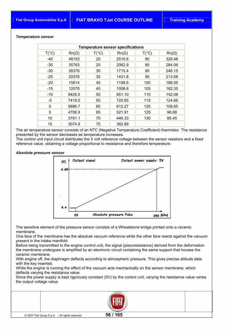
Temperature sensor
Temperature sensor specifications T(°C) Rn(Ω) T(°C) Rn(Ω) T(°C) Rn(Ω) -40 48153 20 2510.6 80 329.48 -35 35763 25 2062.9 85 284.06 -30 26376 30 1715.4 90 246.15 -25 20376 35 1431.8 95 213.68 -20 15614 40 1199.6 100 186.00-15 12078 45 1008.6 162.35 105 -10 9426.0 50 851.10 110 142.08 -5 7419.0 55 720.65 115 124.66 0 5886.7 60 612.27 120 109.65 5 4706.9 65 521.91 125 96.68
10 3791.1 70 446.33 130 85.45 15 3074.9 75 382.89
The air temperature sensor consists of an NTC (Negati ent) thermistor. The resistance ted by the sensor decreases as temperature increases.
he sensor resistors and a fixed ference value, obtaining a voltage proportional to resistance and therefore temperature.
ve Temperature CoefficipresenThe control unit input circuit distributes the 5 volt reference voltage between tre Absolute pressure sensor
© 2007 Fiat Group S.p.A. – All rights re
The sensitive element of the presmembrane. One face of the membrane has thpresent in the intake manifold. Before being transmitted to the ethe membrane undergoes is ampceramic membrane. With engine off, the diaphragm dewith the key inserted. While the engine is running the edeflects varying the resistance vaSince the power supply is kept rigthe output voltage value.
O
served 56 / 165
sure sensor consists of a W
e absolute vacuum referenc
ngine control unit, the signallified by an electronic circuit
flects according to atmosph
ffect of the vacuum acts melue. orously constant (5V) by th
utput signal
Absolute pressur
heatstone bridge printed onto a ceramic
e while the other face reacts against the vacuum
(piezoresistance) derived from the deformation containing the same support that houses the
eric pressure. This gives precise altitude data
chanically on the sensor membrane, which
e control unit, varying the resistance value varies
Output power supply: 5V
e Pabs

Fiat Group Automobiles S.p.A FIAT BRAVO TJet COURSE OUTLINE Training Academy
Electrical connections
Pin 1 ground Pin 2 air temperature sensor signal Pin 3 5 V power supply Pin 4 intake manifold air pressure signal
Test 1056BU – Intake air temperature and/or pressure sensor function check STEP CHECK SOLUTION IF CHECK NOT OK
1 of the pressure sensor connector Turn the key to RUN Check for voltage of approx. 5 Volts
and theIf powunit output replace the ECH control unit [PR_1056B82]
Sensor power supply check Connect the Examiner in voltmeter mode to pins 1 and 3
Restore continuity of wiring between the engine control unit
pressure sensor. er is interrupted at control
2 Start the engine
Pressure signal check Connect the Examiner in voltmeter mode: black pin to pin 1 of the sensor and red pin to pin 4
Replace the intake air temperature/pressure sensor
Check for voltage signal of approx. 1 volt and that the creases as per the graph on acceleration
[PR_1056B54]
value inTemperature signal
3 Connect the Examiner in Ohmmeter mode to senso1 and 2.
check sor connector
r pins
Check for resistance as per the characteristic curve.
Replace the intake air temperature/pressure sensor [PR_1056B54]
Disconnect the sen
4
57 / 165
PRESSURE sensor
G
out
round
© 2007 Fiat Group S.p.A. - All rights reserved
put) Ua (Signal

Fiat Group Automobiles S.p.A FIAT BRAVO TJet COURSE OUTLINE Training Academy
Turbo pressure sensor
ype a sensor consisting of a Wheatstone bridge printed onto a ceramic membrane.
Function he turbo pressure sensor is used by the Engine Contr l Hub to calculate turbocharge pressure downstream
intercooler.
ounted on the intake pipes in a specific housing before the motorized throttle valve.
ge the turbocharge pressure, and to estimate the mass of air the cylinder, used to meter the fuel.
÷ 250 kPa +/- 3,4 kPa
Electri
TThe turbo pressure sensor is
T oof the Location
he sensor is mT Specifications and function The sensor has the same features as the intake air pressure sensor.
he Engine Control Hub uses this signal to manaTtrapped in
ain functional parameters M Pressure range: 20
Main electrical interface parameters
Power supply: 5 V from ECU Current at 5 V: 9 mA Absorption: max 0.1 mA Pressure signal: analogue (%of power supply voltage) Resistor load: Rpull-up = 680 kΩ
cal connections
© 2007 Fiat Group S.p.A. – All rights reserved 58 / 165
Pin 1 5 V power supply Pin 2 ground signal Pin 3 turbo pressure signal

Fiat Group Automobiles S.p.A FIAT BRAVO TJet COURSE OUTLINE Training Academy
Test 1064 BI – Turbo sensor function check STEP CHECK SOLUTION IF CHECK NOT OK
1
Sensor power supply check Connect with the Examiner in Voltmeter mode to pins 1 and 2 of the pressure sensor connector Turn the ignition key to RUN Check presence of approx. 5 Volt voltage
Restore continuity of the wire between engine control hub and pressure sensor. If power is interrupted at the engine control hub out, replace the control hub [PR_1056B82]
2
Pressure signal check Connect with the Examiner in Voltmeter mode. black pin to pin 2 of the sensor and red pin to pin 3 Start the engine Check for presence of 1.5 Volt signal and that this increases up to approx 4.5 Volts on acceleration
Replace the turbo sensor [PR_1064B26]
Atmospheric pressure sensor
ph es to measure atmospheric pressure.
ilt-in to the Engine Control Hub
pecifications and function he information is used by the ECH to correct the quantity of air drawn in by the engine according to altitude. his information is used to calculate injection time and ignition point, as well as to control the turbocompressor.
Type The atmos eric pressure sensor serv
ocation LThe sensor is bu STT
59 / 165 © 2007 Fiat Group S.p.A. - All rights reserved

Fiat Group Automobiles S.p.A FIAT BRAVO TJet COURSE OUTLINE Training Academy
Pinging sensor
Type The pinging sensor is piezoelectric type. Function The pinging sensor is used by the Engine Control Hub to recognise pinging in the combustion chamber.
the crankcase to the rear, and detects the intensity of the vibration caused by premature ignition in the combustion chamber. Specifications and function
Location The sensor is mounted on
The molecules of a quartz
rest conditions (A) the mcrystal are characterised by electrical polarisation. olecules do not have any particular alignment.
hen the crystal is subject to pressure or is struck (B), the molecules align the more the higher the pressure is subjected to.
ance until the phenomenon ceases. ually restored to low values.
InWthe crystal This alignment produces a voltage at the crystal terminals, which is interpreted and adapted over time (shifts due to engine ageing) by the Engine Control Hub, permitting recognition of engine knock in order to reduce
nition advigFollowing this, advance is grad
© 2007 Fiat Group S.p.A. – All rights reserved 60 / 165
A. Rest position B. Position under pressure Electrical specifications Resistance at sensor terminals is about 4,87 Mohm +/- 20%
Fiat Group Automobiles S.p.A FIAT BRAVO TJet COURSE OUTLINE Training Academy
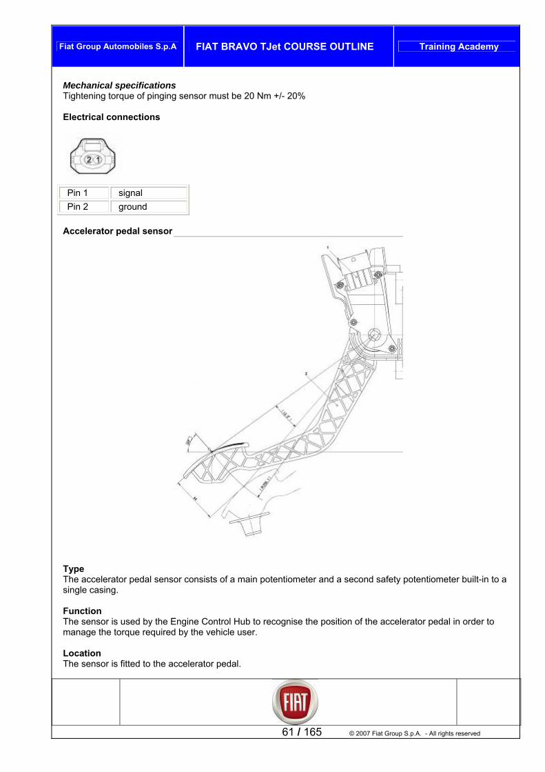
Mechanical specifications Tightening torque of pinging sensor must be 20 Nm +/- 20% Electrical connections
Pin 1 signal Pin 2 ground
Accelerator pedal sensor
edal sensor consists of a main potentiometer and a second safety potentiometer built-in to a ingle casing.
Function The sensor is used by the Engine Control Hub to recognise the position of the accelerator pedal in order to manage the torque required by the vehicle user. Location
he sensor is fitted to the accelerator pedal.
Type The accelerator ps
61 / 165 © 2007 Fiat Group S.p.A. - All rights reserved
T

Fiat Group Automobiles S.p.A FIAT BRAVO TJet COURSE OUTLINE Training Academy
SpecifiThe sensor
catio n c ing, fastened to the accelerator pedal support, which contains a shaft mounted in
l posi to the dual track potentiometer. g exe nce to pressure on the shaft, while another spring assures pedal return on
lease. he injection control unit actuates the following "recovery'" strategies in the following conditions:
in case of failure of one of the two potentiometers, the control unit uses the remaining track, without limiting torque, and controls plausibility with the brake switch.
in case of total failure of both potentiometers, it disables throttle aperture. Diagram of inside accelerator pedal sensor
ns and functioonsists of a cas
an axia tion and connectedA sprin rts the correct resistareT
Electrical specifications Power supply 5V +/-03V Series resistance and contact resistance RS+RC 1Kohm +/- 04ohm Potentiometer resistance RN1 1.2 Kohm +/- 05 Kohm Potentiometer resistance Rn2 1.7 kohm +/- 08 Kohm Electrical connections
Pin 1 potentiometer 2 5V power supply
© 2007 Fiat Group S.p.A. – All rights reserved 62 / 165
Pin 2 potentiometer 1 5V power supply Pin 3 potentiometer 1 ground Pin 4 potentiometer 1 signal

Fiat Group Automobiles S.p.A FIAT BRAVO TJet COURSE OUTLINE Training Academy
Pin 5 potentiometer 2 ground Pin 6 potentiometer 2 signal Lambda probe
ipologia h Lambda probes Bosch LSF4.2 are both (pre-catalyser and post-catalyser) planar type
ne bda
Checking combustion performance (stoichiometric ratio) (Pre Cat) Making the self-adaptation corrections (Pre Cat) Checking the functional status of the catalytic converter (post Cat)
Note: to obtain an optimal fuel/air mixture, the quantity of air drawn in by the engine has to be equal to the theoretical quantity that serves to burn all the fuel injected. In this case the Lambda factor (I), which is the ratio between the quantity of air taken in and the theoretical quantity of air (to burn all the fuel injected) is equal to 1. Therefore: Lambda = 1 ideal mixture Lambda > 1 lean mixture Lambda < 1 rich mixture
TT e FunzioThe Lam probes are used by the Engine Control Hub for:
63 / 165 © 2007 Fiat Group S.p.A. - All rights reserved
Post Cat probe Pre Cat probe

Fiat Group Automobiles S.p.A FIAT BRAVO TJet COURSE OUTLINE Training Academy
Rich mixture (lack of air)
catalytic converter and the second in the section downstream of the onverter.
e
he Lambda probe is heated by the injection control unit proportionally to the temperature of the exhaust gases. This prevents heat shock to the ceramic body due to contact with condensation, present in the exhaust gas when the engine is cold. The measuring cell and the heater are built-in to the “planar” (stratified) ceramic element, with the advantage of obtaining rapid heating of the cell, such as to permit “closed loop” (Lambda = 1) control within 10 seconds of starting the engine.
Lean mixture (excess air) Location The first probe is fitted downstream of thec Specifications and function When it comes into contact with exhaust gases, the Lambda probe generates an electrical signal, the voltage value of which depends on the concentration of oxygen present in the gases themselves. This voltage is characterised by an abrupt variation when the composition of the mixture shifts from the valuLambda = 1. T
1. Connecting element 2. Protective sleeve 3. Planar sensor element 4. Ceramic support pipe 5. Probe seat 6. Ceramic gasket 7. Protective pipe
© 2007 Fiat Group S.p.A. – All rights reserved 64 / 165

Fiat Group Automobiles S.p.A FIAT BRAVO TJet COURSE OUTLINE Training Academy
Lambda probe function is based on the principle of an oxygen concentration cell with solid electrolyte. The surfaces of the measuring cell are lined with microporous layers of inert material.
1. Side exposed to exhaust gas 2. Side exposed to atmosphere 3. Heating element 4. Probe terminals where potential difference is generated
Heater electrical specifications Nominal voltage 12V Maximum voltage 14V Nominal power 7W 9 ohm resistance at 20°C Maximum current 2.1 A at 13 V Tightening torque 45 +/-4,5 Nm
onnections Electrical cPre Cat probe
Pin 1 signal Pin 2 ground signal Pin 3 heater command Pin 4 12 V power supply
Post Cat probe
Pin 1 signal
65 / 165 © 2007 Fiat Group S.p.A. - All rights reserved
Pin 2 ground signal Pin 3 heater command Pin 4 12 V power supply

Fiat Group Automobiles S.p.A FIAT BRAVO TJet COURSE OUTLINE Training Academy
Engine oil pressure sensor
T
he sensor is a contact type sensor.
unction
ype T F
The pressure sensor is used by the control unit to recognise the preset engine oil pressure value. Theis se
signal gic for lighting the warning light on the
insnt via C-CAN network to the Body Computer Hub to manage the lo
trument panel. Location The sensor is positioned on the engine oil filter support Electrical connections
Pin 1 connection with the Engine Control Hub
© 2007 Fiat Group S.p.A. – All rights reserved 66 / 165

Fiat Group Automobiles S.p.A FIAT BRAVO TJet COURSE OUTLINE Training Academy
Stop pedal switch
Type Two stage switch
he stop pedal switch is used by the Engine Control Hub to manage strategies associated with driveability LocaThe switch is n the brake pedal Specification n
itch co s two switches, one normally open (N.O) and one normally losed (N.C).
gram below shows the electrical circuit in brake pedal pressed condition, and its functional principle
Function T
tion located o
s and functionsists of a container that containThe sw
cWhen operating, the N.O switch closes while the N.C switch opens, so the N.C. switch serves to recognise brake pedal at rest and the N.O switch serves to recognise brake pedal pressed.
he diaT
67 / 165 © 2007 Fiat Group S.p.A. - All rights reserved
Key: A . power supply positive B. power to electrical user C/D redundant control switch. P brake pedal pressed state R brake pedal released Note: at approx. half of the pedal excursion both switches are closed. This situation is used to test the coherence of the signals from the two switches.

Fiat Group Automobiles S.p.A FIAT BRAVO TJet COURSE OUTLINE Training Academy
Electrical connections
normally closed switch signal Pin 1 Pin 2 normally open switch signal Pin 3 normally closed switch power under key Pin 4 normally open switch power under key Clutch pedal switch
Tipologia
ic switch ElectrFunz e
tegies associated with driveability
he switch is fitted to the clutch pedal. ote: the switch is not present on versions with MTA gearbox.
Specifications and function The switch consists of a container with a normally open switch (N.O) that closes when the clutch pedal is pressed.
ion lutch pedal switch is used by the Engine Control Hub to manage straThe c
bicazione U
© 2007 Fiat Group S.p.A. – All rights reserved 68 / 165
TN

Fiat Group Automobiles S.p.A FIAT BRAVO TJet COURSE OUTLINE Training Academy
Electrical connections
Pin 1 N.C. Pin 2 connection to chassis ground Pin 3 N.C. Pin 4 switch signal
Linear pressure switch (air-conditioner)
69 / 165 © 2007 Fiat Group S.p.A. - All rights reserved
Type Linear pressure switch Function The linear pressure switch controls the correct function of the system substituting the function of the quadrinary pressure switch. It is used by the Engine Control Hub to:
Control activation of the conditioner compressor safety function Control activation of the engine cooling fan.
Location The switch is fitted on the air-conditioner system high pressure circuit. Specifications and function Each change in pressure corresponds to a voltage signal. The operating range of the linear sensor varies from 3.018 bar up to 29.508 bar as per the characteristic pressure curve (Bar) over the output voltage percentage (%Vdc). Compressor operation is enabled and fan speed adjusted according to the variation in pressure that takes place in this range. Below these values the compressor is disabled as a safety condition to prevent damage to the system itself.

Fiat Group Automobiles S.p.A FIAT BRAVO TJet COURSE OUTLINE Training Academy
Electrical specifications Power supply voltage 5V+/-10% Tempe 5°C ÷ 80°C
Max s
Tightening torque is 8.5 +/-3 Nm
rature range -Power supply current 7mA Mechanical specification
Note. Pressures are expressed in KPa Electrical connections
© 2007 Fiat Group S.p.A. – All rights reserved 70 / 165
Pin 1 Ground Pin 2 Power supply voltage Pin 3 Output signal
Note: the power supply voltage may vary by +/- 10% and sensor operating temperature is between 5°C and 80°C.

Fiat Group Automobiles S.p.A FIAT BRAVO TJet COURSE OUTLINE Training Academy
Cruise control stick
TC ro s incorporated in a specific control stick Function
he switches are used by the Engine Control Hub to: vate the cruise control function;
Set/adjust vehicle speed; Resume previously set function
ion
The i specific control stick fastened to the combiswitch Spe unction
ype ruise Cont l function command switche
T Acti
Locat sw tches are on a
cifications and f
71 / 165 © 2007 Fiat Group S.p.A. - All rights reserved
The petrol engine control system with motorised throttle valve and electronic injection time control have cruise control among their available functions, or the possibility of automatically maintaining the vehicle at a cruising speed set by the driver. The combiswitch group includes a lever with all the cruise control buttons, and specifically:
The system enable/disable ring switch; The lever with vehicle speed increase( SET +) / decrease (SET-) controls; The Resume button to resume a previously memorised speed.
The electronic system is controlled by the Engine Control Hub. It automatically maintains the cruising speed set by the driver by directly controlling the engine.

Fiat Group Automobiles S.p.A FIAT BRAVO TJet COURSE OUTLINE Training Academy
Electrical connections
Pin 1 RESUME button signal Pin 2 + 12V power supply Pin 3 N.C. Pin 4 ON/OFF switch signal Pin 5 SET + signal Pin 6 SET - signal
© 2007 Fiat Group S.p.A. – All rights reserved 72 / 165
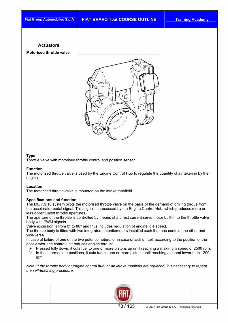
Fiat Group Automobiles S.p.A FIAT BRAVO TJet COURSE OUTLINE Training Academy
Actuators Motorised throttle valve
ype hrottle valve with motorised throttle control and position sensor
unction he motorised throttle valve is used by the Engine Control Hub to regulate the quantity of air taken in by the
ocation The motorised throttle valve is mounted on the intake manifold Specifications and function The ME 7.9.10 system pilots the motorised throttle valve on the basis of the demand of driving torque from the accelerator pedal signal. This signal is processed by the Engine Control Hub, which produces more or less accentuated throttle apertures. The aperture of the throttle is controlled by means of a direct current servo motor built-in to the throttle valve body with PWM signals. Valve excursion is from 0° to 80° and thus includes regulation of engine idle speed. The throttle body is fitted with two integrated potentiometers installed such that one controls the other and vice-versa. In case of failure of one of the two potentiometers, or in case of lack of fuel, according to the position of the accelerator, the control unit reduces engine torque:
Pressed fully down, it cuts fuel to one or more pistons up until reaching a maximum speed of 2500 rpm. In the intermediate positions, it cuts fuel to one or more pistons until reaching a speed lower than 1200
rpm. Note: If the throttle body or engine control hub, or air intake manifold are replaced, it is necessary to repeat the self-teaching procedure.
TT FTengine.
73 / 165 © 2007 Fiat Group S.p.A. - All rights reserved
L

Fiat Group Automobiles S.p.A FIAT BRAVO TJet COURSE OUTLINE Training Academy
Electrical connections
Pin 1 Throttle aperture servo ground Pin 2 TPS1 and TPS2 potentiometer ground Pin 3 TPS1 and TPS2 potentiometers 5V pos. Pin 4 Throttle aperture servo positive Pin 5 TPS2 potentiometer signal Pin 6 TPS1 potentiometer signal
Injectors
© 2007 Fiat Group S.p.A. – All rights reserved 74 / 165
Key 1. Seal on rail 2. Seal on intake manifold 3. Connector 4. Reference mark for correct assembly
Type Bosch EV14 ET Top Feed electroinjectors (fuel intake from top part of injector, where electromagnet is housed. Function Used by Engine Control Hub to inject fuel into the intake ducts behind the intake valves.
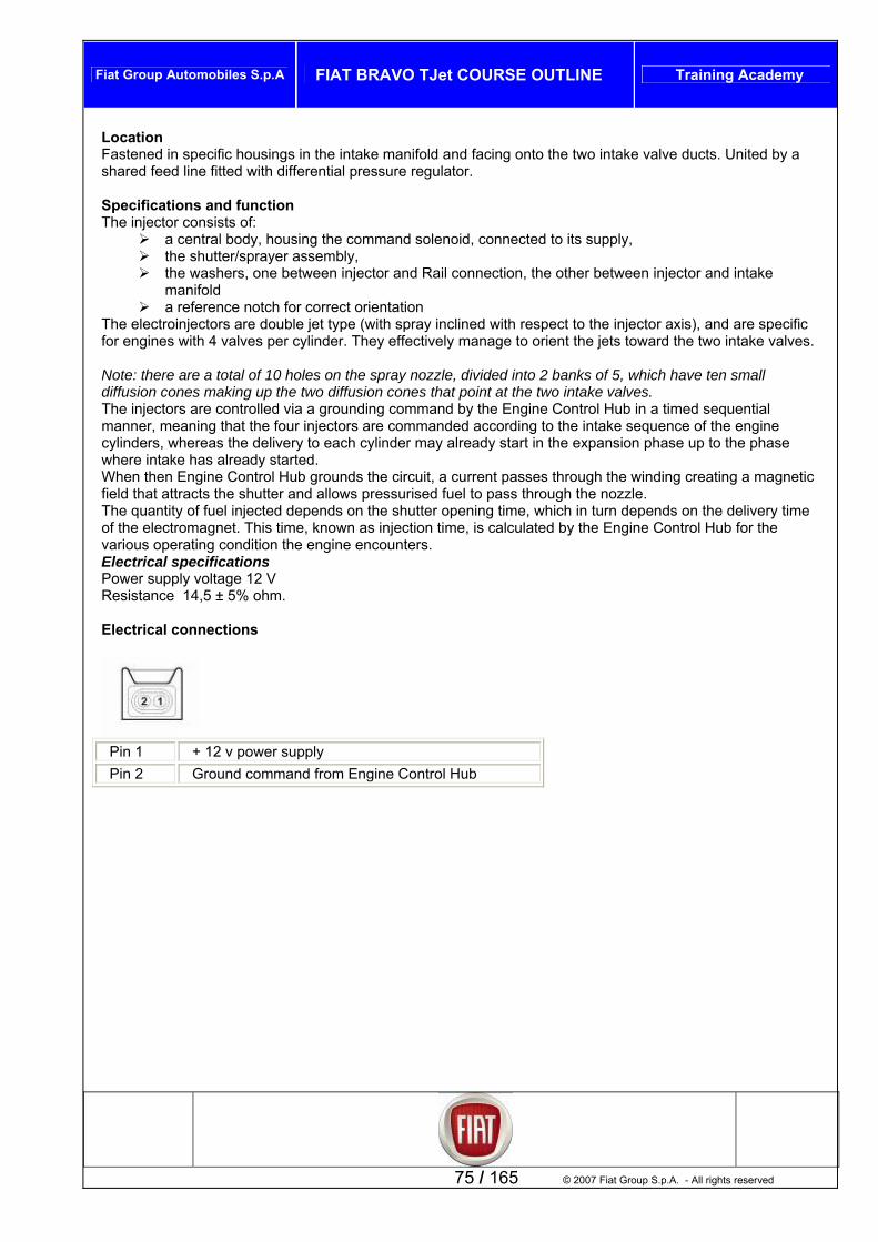
Fiat Group Automobiles S.p.A FIAT BRAVO TJet COURSE OUTLINE Training Academy
Location Fastened in specific housings in the intake manifold and facing onto the two intake valve ducts. United by a
ic es.
sion cones that point at the two intake valves. ub in a timed sequential
here intake has already started. ds the circuit, a current passes through the winding creating a magnetic
fuel to pass through the nozzle. g time, which in turn depends on the delivery time
own as injection time, is calculated by the Engine Control Hub for the gine encounters.
lectrical specifications
Electrical connections
shared feed line fitted with differential pressure regulator. Specifications and function The injector consists of:
a central body, housing the command solenoid, connected to its supply, the shutter/sprayer assembly, the washers, one between injector and Rail connection, the other between injector and intake
manifold a reference notch for correct orientation
The electroinjectors are double jet type (with spray inclined with respect to the injector axis), and are speciffor engines with 4 valves per cylinder. They effectively manage to orient the jets toward the two intake valv Note: there are a total of 10 holes on the spray nozzle, divided into 2 banks of 5, which have ten small diffusion cones making up the two diffuThe injectors are controlled via a grounding command by the Engine Control Hmanner, meaning that the four injectors are commanded according to the intake sequence of the engine cylinders, whereas the delivery to each cylinder may already start in the expansion phase up to the phase wWhen then Engine Control Hub grounfield that attracts the shutter and allows pressurisedThe quantity of fuel injected depends on the shutter openinof the electromagnet. This time, kn
e envarious operating condition thEPower supply voltage 12 V Resistance 14,5 ± 5% ohm.
Pin 1 + 12 v power supply
75 / 165 © 2007 Fiat Group S.p.A. - All rights reserved
Pin 2 Ground command from Engine Control Hub

Fiat Group Automobiles S.p.A FIAT BRAVO TJet COURSE OUTLINE Training Academy
TEST_1056BA Injector function test
STEP CHECK SOLUTION IF CHECK NOT OK
1 fuConnect the voltmeter between the p
InSe e curve. Fr
ins of the faulty
Restore wiring between engine control unit and injector. If the signal is interrupted at the control unit output replace the engine control unit
6B82]
jection signal check t the diagnosis tool to read the voltag
om the “TOOLS” menu select the “VOLTMETER” nction with time base set to 1 second.
injector (using sectioner AD 233 N° 1806387000). Press the “START” button on the diagnosis tool to start
[PR_105
curve acquisition. Turn the engine over and check that the signal is as per the graph provided
2
F22 in the entifying the
cause.
Injector power supply check powered [EL_5030]
Replace 15A fuseengine bay after idCheck that the injectors are correctly
Proceed to step 4
Restore correct power supply to the injectors
3 the terminals and then check resistance: the value must be 14 Ohm ± 10% at 20°C
Injector resistance check Disconnect the injector Connect the Examiner tool in Ohmmeter mode between
Replace the injector [PR_1056B70]
© 2007 Fiat Group S.p.A. – All rights reserved 76 / 165
Breaker AD 233 connection
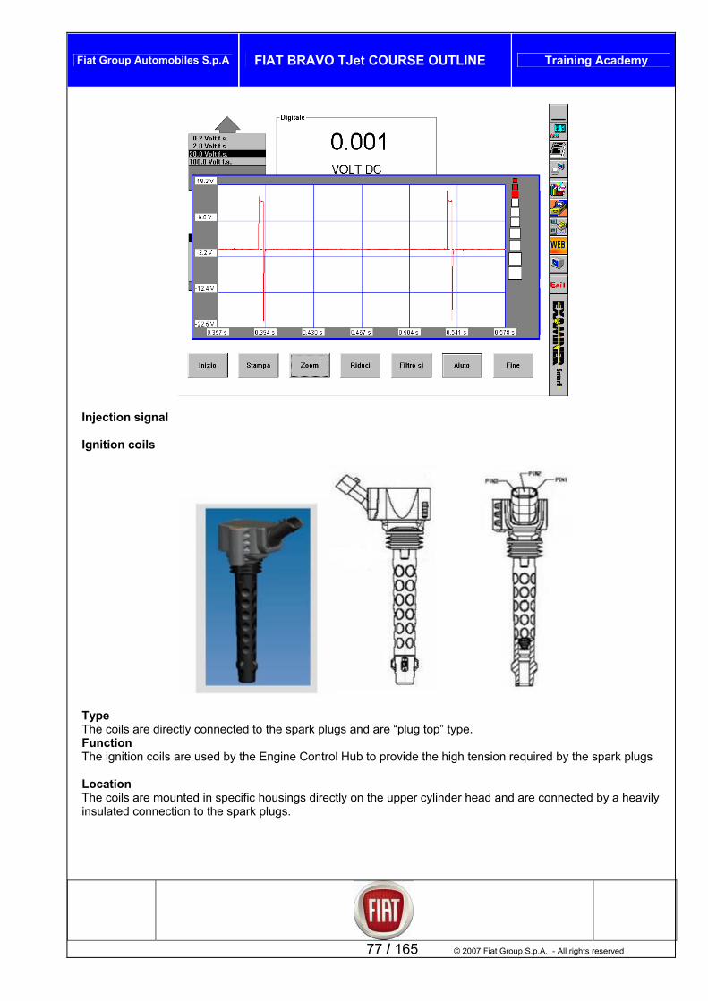
Fiat Group Automobiles S.p.A FIAT BRAVO TJet COURSE OUTLINE Training Academy
Inj i
77 / 165 © 2007 Fiat Group S.p.A. - All rights reserved
ect on signal Ignition coils
Type The coils are directly connected to the spark plugs and are “plug top” type. Function The ignition coils are used by the Engine Control Hub to provide the high tension required by the spark plugs Location The coils are mounted in specific housings directly on the upper cylinder head and are connected by a heavily insulated connection to the spark plugs.

Fiat Group Automobiles S.p.A FIAT BRAVO TJet COURSE OUTLINE Training Academy
Specifications and function
The coils co re (double E) ead, and the prim .The winding engine hea poxy resin which has thermal pro Thplug with a igto the sparkThe coils ar ording toThe power The Engine reaprimary. Wh oltage is generated on the secondary winding by induction.
h vo ectrodes of the spark plug, generating the park that ignites the air/fuel mixture. ote: the type of spark depends on the dielectric between the two electrodes he Engine Control Hub grounds the primary circuit considering the calculated injection advance and coil harging time.
lectrical specifications rimary circuit resistance 0,53 ohm +/- 5% a 23°C econdary circuit resistance 8,1 kohm +/- 5% a 23°C ominal current on primary 7,3 A oltage on secondary 27 kV
echanical specifications ightening torque on screw fastening upper head 8 +/-1 Nm
specifications
nsist of a lamellar packed magnetic internal co in silicon steel, along the coil h ary and secondary windings are arranged around the core
s are inserted in a moulded plastic container, which carries the low voltage connector and the optimal dielectric, mechanical and e coil head is connected to the spark
h voltage from the secondary winding
d mounting, and is totally insulated in eperties, since the coils are exposed to high temperatures. silicone rubber cap containing a spring that transfers the h plug terminal.
the Engine Control Hub acce directly controlled by a sequential timed logic.
ting a strong magnetic field on the drivers are integrated into the Engine Control Hub Control Hub grounds the primary winding power circuit cen the primary circuit is opened, a high v
This higs
ltage is discharged to the engine ground through the el
NTc EPSNV MT Spark plug
Note: The only certified spark plugs are the NGK IKR9F8 with air gap of 0.75+/-0.05.
ote: The secondary cannot be cheN cked only with ohmmeter as the circuit is fitted with a protective diode.
© 2007 Fiat Group S.p.A. – All rights reserved 78 / 165
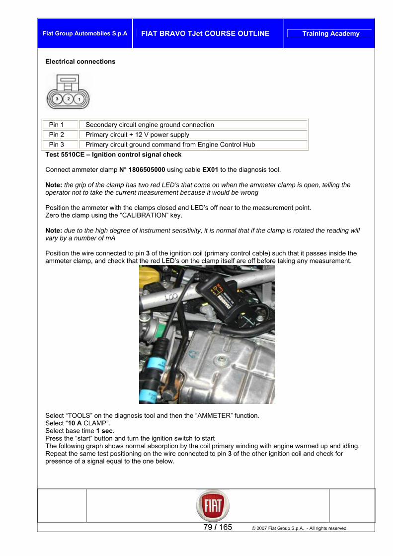
Fiat Group Automobiles S.p.A FIAT BRAVO TJet COURSE OUTLINE Training Academy
Electrical connections
Pin 1 Secondary circuit engine ground connection Pin 2 Primary circuit + 12 V power supply Pin 3 Primary circuit ground command from Engine Control Hub
Test 5510CE – Ignition control signal check
onnect ammeter clamp N° 1806505000 using cable EX01 to the diagnosis tool.
p has two red LED’s that come on when the ammeter clamp is open, telling the perator not to take the current measurement because it would be wrong
s off near to the measurement point. p using the “CALIBRATION” key.
Note: due to the high degree of instrument sensitivity, it al that if the clamp is rotated the reading will vary by a number of mA
ch that it passes inside the mmeter clamp, and check that the red LED’s on the clamp itself are off before taking any measurement.
C Note: the grip of the clamo Position the ammeter with the clamps closed and LED’Zero the clam
is norm
Position the wire connected to pin 3 of the ignition coil (primary control cable) sua
79 / 165 © 2007 Fiat Group S.p.A. - All rights reserved
Select “TOOLS” on the diagnosis tool and then the “AMMETER” function. Select “10 A CLAMP”. Select base time 1 sec. Press the “start” button and turn the ignition switch to start The following graph shows normal absorption by the coil primary winding with engine warmed up and idling. Repeat the same test positioning on the wire connected to pin 3 of the other ignition coil and check for presence of a signal equal to the one below.

Fiat Group Automobiles S.p.A FIAT BRAVO TJet COURSE OUTLINE Training Academy
Regular ignition signal
Interrupted or grounded ignition signal.
I ition ck continuity and insulation to ground of the
llowing cables: between ignition coil and engine control hub
f the ign control signals to the coil are not present, che
© 2007 Fiat Group S.p.A. – All rights reserved 80 / 165
fo

Fiat Group Automobiles S.p.A FIAT BRAVO TJet COURSE OUTLINE Training Academy
Test 5510 No the c P-02 is c aking all connection NIT TEST, by active diagnosi rting manoeuvre age to the lambda pr rter STEP SOLUTI OT OK
CI – Ignition coil function check
te: heck for spark or no spark between the contacts of the gap Ss, by starting the engine, or, in CONTROL U
d to prevent dam
arried out after ms. In the case of sta
, the fuel pump must be disable obe or catalytic conve
ON IS CHECK NCHECK
1
ey is turned to STOP
SP-02 n° 1806369000 between the HT
dapter cable N° 3
he other coils.
Restore the coil primary control circuit Replace
rol sIf the co : restore between e control hub and
e coil.If the co d at the cont the
e c ]
IGNITION SIGNAL CHECK Check that the ignition kDisconnect the battery negative leadRemove pump 15A fuse F21 in the Engine Control Hub in the engine bay
cont
Remove the HT coil from its housing Fit the spark gapoutput of the single coil and the ground on the engine block as shown in fig. 1, using a
th
Reconnect the battery Turn the key to start and check for a spark between the contacts of gap SP-02. Repeat the same test on t
engin
Using the Examiner, check for errors and delete them
the coil if the primary ignal is present ntrol signal is interruptedcontinuity of the wiring the engin
ntrol signal is interrupte
erol hub output, replacontrol hub [PR_1056B82
Fig. 1 1 – Spark gap SP-02 2 – Adapter cable n° 3 3 - Single coil Test 5510OB – Ignition coil resistance check Connect to the terminals of the primary circuit between pins 2 and 3 and check that the resistance values are within the following values: Minimum value: 0.65 Ohm
81 / 165 © 2007 Fiat Group S.p.A. - All rights reserved
3
1
2

Fiat Group Automobiles S.p.A FIAT BRAVO TJet COURSE OUTLINE Training Academy
Maximum value: 0.90 Ohm Ignition coil connector To check the secondary circuit, carry out Test 5510CI DUMP valve
© 2007 Fiat Group S.p.A. – All rights reserved 82 / 165
Type By-pass valve on intake ducts electrically controlled by the Engine Control Hub Function The dump valve is controlled by the Engine Control Hub to limit the overpressure in the duct downstream of the compressor, when the throttle is suddenly closed after a release manoeuvre. These pressure peaks could slow the turbocompressor impeller, causing strong vibration and noise. Location The dump valve is mounted in a specific housing on the intake duct upstream of the throttle

Fiat Group Automobiles S.p.A FIAT BRAVO TJet COURSE OUTLINE Training Academy
Specifications and function
The electrovalve consists of an outer body housing a mechanical membrane valve (1) with a return spring (2),
nd an electromagnet (3) powered by the Engine Control Hub through the connector provided. ntrol Hub excites the electromagnet (3) that pulls the mechanical valve (1) that
pens a by-pass and discharges excess pressure from the intake ducts upstream of the turbocompressor. Having completed this task, the Engine Control Hub opens the electromagnet circuit allowing the return spring
xtend and close the mechanical valve.
Pneumatic vPre bar
Seepage: max 330 l/h at 80 kPa Electrical specifications
power supply voltage: 12 V working voltage: 8 ÷16 V absorption: 1.4 A (at 13V and 25°C)
aOn release the Engine Coo
to
e
alve main function parameters ssure ratio (p2/p1): 2.5
electromagnet internal resistance 14 Ω±10% at 20 °C Electrical connections
83 / 165 © 2007 Fiat Group S.p.A. - All rights reserved
Pin 1 + 12 V power supply Pin 2 Ground command from Engine Control Hub
Test 1064BH – Turbo air by-pass electrovalve function check (shut-off) Note : this is a normally closed electrovalve, and is opened with a voltage signal from the engine control hub when the accelerator is released to discharge the backpressure generated between throttle closed (on releasing the accelerator) and the pressure of the turbine in motion, to prevent turbine stall. It is closed when acceleration is demanded again or with the engine idling.
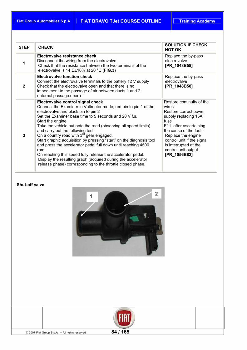
Fiat Group Automobiles S.p.A FIAT BRAVO TJet COURSE OUTLINE Training Academy
STEP CHECK SOLUTION IF CHECK NOT OK
1 Electrovalve resistance check Disconnect the wiring from the electrovalve Check that the resistance between the two terminals of electrovalve is 14 Ω±10% at 20 °C (FIG.3)
the [PR_1048B58]
Replace the by-pass electrovalve
2 2 V supply
is no and 2
[PR_1048B58]
Electrovalve function check Connect the electrovalve terminals to the battery 1Check that the electrovalve open and that thereimpediment to the passage of air between ducts 1 (internal passage open)
Replace the by-pass electrovalve
3
pin 1 of the
rd gear engaged. y pressing “start” on the diagnosis tool
00
the accelerator
se.
Restore continuity of the wires Restore correct power supply replacing 15A fuse F11 after ascertaining the cause of the fault. Replace the engine control unit if the signal
Electrovalve control signal check Connect the Examiner in Voltmeter mode; red pin to electrovalve and black pin to pin 2 Set the Examiner base time to 5 seconds and 20 V f.s. Start the engine Take the vehicle out onto the road (observing all speed limits) and carry out the following test. On a country road with 3Start graphic acquisition band press the accelerator pedal full down until reaching 45rpm. On reaching this speed fully release the accelerator pedal.Display the resulting graph (acquired duringrelease phase) corresponding to the throttle closed pha
is interrupted at the control unit output [PR_1056B82]
© 2007 Fiat Group S.p.A. – All rights reserved 84 / 165
Shut-off valve
1 2

Fiat Group Automobiles S.p.A FIAT BRAVO TJet COURSE OUTLINE Training Academy
Shut-off electrovalve command signal
urbo waste gate pressure electrovalve
ction,
T
Type By-pass solenoid valve for controlling turbo pressure
85 / 165 © 2007 Fiat Group S.p.A. - All rights reserved
Function The turbo pressure electrovalve is used by the Engine Control Hub to control turbo pressure by direct avia compressed air connections on the waste gate valve
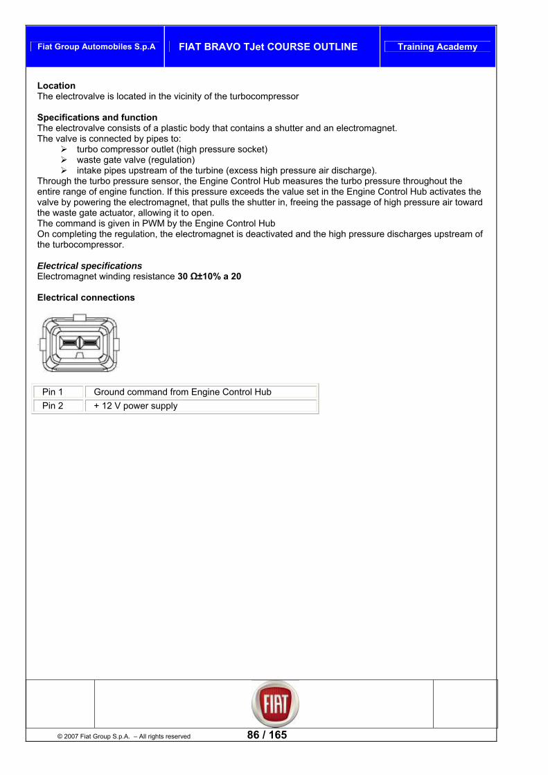
Fiat Group Automobiles S.p.A FIAT BRAVO TJet COURSE OUTLINE Training Academy
Location The electrovalve is located in the vicinity of the turbocompressor
Specifications and function he electrovalve consists of a plastic body that contains a shutter and an electromagnet.
lve is connected by pipes to:
waste gate valve (regulation) take pipes upstream of the turbine (excess high pressure air discharge).
hout the ctivates the
wering the electromagnet, that pulls the shutter in, freeing the passage of high pressure air toward
he command is given in PWM by the Engine Control Hub he electromagnet is deactivated and the high pressure discharges upstream of
Electrical specifications Electromagnet winding resistance 30 Ω±10% a 20 Electrical connections
TThe va
turbo compressor outlet (high pressure socket)
inThrough the turbo pressure sensor, the Engine Control Hub measures the turbo pressure throug
ntire range of engine function. If this pressure exceeds the value set in the Engine Control Hub aevalve by pothe waste gate actuator, allowing it to open. TOn completing the regulation, tthe turbocompressor.
Pin 1 Ground command from Engine Control Hub Pin 2 + 12 V power supply
© 2007 Fiat Group S.p.A. – All rights reserved 86 / 165

Fiat Group Automobiles S.p.A FIAT BRAVO TJet COURSE OUTLINE Training Academy
Test 1064BB – Turbo pressure control electrovalve function check
OLUTION IF CHECK NOT OK
STEP CHECK S
1 Electrovalve resistance check Disconnect the wiring from the electrovalve Check that the resistance between the two terminals of the electrovalve is 30 Ω±10% a 20 °C (fig. 3)
Replace the turbo pressure control electrovalve [PR_1064B34]
2
eck .3) n.° 2000015500 to
f the turbo pressure electrovalve mp at pressure of approx. 0.50 bar
o impediment to air passage between connector 1 and 2 Connect the terminals of the electrovalve to the 12V supply from the battery (using sectioner AD 233 N° 1806387000) Operate the pump at pressure lower than 0.50 bar (to prevent damage to the electrovalve) Ch etween connector 1 and 2 is clo(in
Replace the turbo pressure control electrovalve [PR_1064B34]
Electrovalve function chcuum pump (figConnect va
connector 1 oOperate the puCheck that there is n
eck that air passage bsed ternal passage closed)
3
e control electrovalve command signal check onnect the Examiner in Voltmeter mode: (using
sectioner AD 233 N° 1806387000) connect the red pin to pin 2 of the valve and the black pin to pin 1 Set the Examiner base time to 2 seconds and 20 V f.s. Start the engine
er the graph
Restore continuity of wiring between engine control hub and electrovalve. If the signal is interrupted at control unit output, replace the engine control hub [PR_1056B82]
PressurC
Check for square wave signal present as p
87 / 165 © 2007 Fiat Group S.p.A. - All rights reserved
Fig. 3
P 2
1

Fiat Group Automobiles S.p.A FIAT BRAVO TJet COURSE OUTLINE Training Academy
Turbo pressure control electrovalve piloting signal
064BF – Waste-gate control pressure check
Fig. 1 With the engine stopped, over the section between actuator and electrovalve, connect connector EX09 (1) contained in case N° 1806338000) of the diagnosis tool with the corresponding 5 bar p ssure transducer
X06 section, select “intake pressure measurement pressure gauge”.
st. On a c c acquisition by pressing “start” on the diagnosis tool and after approx. 5 seconds in 2 ngine speed to 4000 rpm and engage 3rd gear.
nd read a value of approx. 980 mbar (745 mmHg) at the maximum peak, value of 20 mbar.
Test 1
reEIn the Tools Start the engine and leave it idling, wait for pressure to stabilise. The measured value must not exceed 590 to 720 mbar (450-550 mmHg). On the Examiner, select the “pressure gauge” tool and set for data acquisition in “intake pressure” more with end scale 2000 mmHg and select time 10 seconds. Take t ad (observing all speed limits) and carry out the following tehe vehicle out on the ro
aphiountry road, begin grnd gear bring e
Display the resulting graph a to a pressurecorresponding
© 2007 Fiat Group S.p.A. – All rights reserved 88 / 165
1

Fiat Group Automobiles S.p.A FIAT BRAVO TJet COURSE OUTLINE Training Academy
CANISTER electrovalve
Type Normally closed electrovalve for fuel vapour recirculation. Function Used by the Engine Control Hub to clean the active carbon filters in the antievaporation system Location Mounted on the lower part of the intake manifold, in position not visible Specifications and function
89 / 165 © 2007 Fiat Group S.p.A. - All rights reserved
The electrovalve consists of an outer body in plastic that houses and electromagnet and a shutter. Externally there are two sockets for connecting the antievaporation system pipes The electrovalve is controlled in PWM by the Engine Control Hub according to the mapped strategies. When the electromagnet (1) is excited, it pulls the shutter (2) that overcomes the pressure of the leaf spring (3) opening the hole (4), allowing passage of fuel vapour. Without power the valve is closed, preventing fuel vapour from excessively enriching the mixture. Electrical specifications Power supply voltage: 13.5 V Resistance at 20°C: 26 ohm Piloting frequency: fino a 30 Hz Current absorbed at 13.5 V: 0.5 A

Fiat Group Automobiles S.p.A FIAT BRAVO TJet COURSE OUTLINE Training Academy
Mechanical specifications
hen assembling the valve, position as indicated by arrow A in the figure.
W
Key
CANISTER side socket arrow indicating direction of flow ..intake side socket
lectrical connections
1A2 E
Pin 1 + 12 V power supply Pin 2 Ground control from Engine Control Hub
Fuel pump
Type Fully immersed pump commanded by level indicator.
© 2007 Fiat Group S.p.A. – All rights reserved 90 / 165
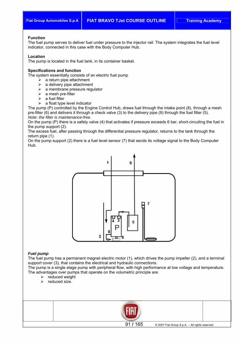
Fiat Group Automobiles S.p.A FIAT BRAVO TJet COURSE OUTLINE Training Academy
Function The fuel pump serves to deliver fuel under pressure to the injector rail. The system integrates the fuel level indicator, connected in this case with the Body Computer Hub. Location The pump is located in the fuel tank, in its container basket. Specifications and function The system essentially consists of an electric fuel pump
a return pipe attachment a delivery pipe attachment a membrane pressure regulator a mesh pre-filter a fuel filter a float type level indicator
The pump (P) controlled by the Engine Control Hub, draws fuel through the intake point (8), through a mesh pre-filter (6) and delivers it through a check valve (3) to the delivery pipe (9) through the fuel filter (5). Note: the filter is maintenance-free. On the pump (P) there is a safety valve (4) that activates if pressure exceeds 6 bar, short-circuiting the fuel in the pump support (2). The excess fuel, after passing through the differential pressure regulator, returns to the tank through the return pipe (1). On the pump support (2) there is a fuel level sensor (7) that sends its voltage signal to the Body Computer Hub.
inal
91 / 165 © 2007 Fiat Group S.p.A. - All rights reserved
Fuel pump The fuel pump has a permanent magnet electric motor (1), which drives the pump impeller (2), and a termsupport cover (3), that contains the electrical and hydraulic connections. The pump is a single stage pump with peripheral flow, with high performance at low voltage and temperature. The advantages over pumps that operate on the volumetric principle are:
reduced weight reduced size.

Fiat Group Automobiles S.p.A FIAT BRAVO TJet COURSE OUTLINE Training Academy
Electrical Specifications: Power supply voltage 12 V Typical current at 13 V 7.5 A
echanical Specifications:
Maximum pressure calibration, 6.50/9.50 bar
est 1040AA – Fuel pump power supply voltage and current absorption test C hat th mp connectors is equal to 12 V Measure pum meter clamp of the diagnosis tool on the pump power s able, p power terminal [EL_5050] C abso T 6BY l supply system delivery pressure check
ect the negative lead from the battery. onnect the diagnosis tool pressure transducer between the delivery pipe (1) and the fuel filter intake
connector (2) using pipe N° 1870885001 (1) (Connector pipes) and pipe N° 2000024501 contained in case N° 2000024500 using Kit EX 07 contained in case N° 1806338000. Connect the battery negative lead. Turn the ignition key to RUN. Within 10 seconds check that the pressure reading on the pressure gauge is approx. 3 bar Start the engine and warm up. Check that pressure is greater than 3.5 bar Note: The fuel pump in the tank switches off after a few seconds.
MFlow-rate = 110 l/h
ressure 4.5-4.9 bar P
T
heck t e pump power supply voltage at the pup current absorption by placing the am
upply current
on the fuse box or directly on the pumrption must be between 6 and 10 A.
est 105isconn
– Fue
© 2007 Fiat Group S.p.A. – All rights reserved 92 / 165
DC

Fiat Group Automobiles S.p.A FIAT BRAVO TJet COURSE OUTLINE Training Academy
Test 1056BI – Fuel supply return system return pressure check isconnect the negative lead from the battery.
s tool pressure transducer between the return pipe (2) and the pipe connector (1) using
DConnect the diagnosiKit N° 1870885001 (connector pipes with the EX 07 kit in case N° 1806338000 Reconnect the battery negative lead. S tart the engine and check that the pressure reading on the pressure gauge is between 0.6 and 0.8 bar
12
93 / 165 © 2007 Fiat Group S.p.A. - All rights reserved
2
1

Fiat Group Automobiles S.p.A FIAT BRAVO TJet COURSE OUTLINE Training Academy
Fuel level indicator Resistance of level sensor according to quantity of fuel in tank.
C
B C D E F
alibrated level A Float height measurement in 157.7 121.9 (mm) +/- 0.8 +/- 0.6 +/- 0.4 +/- 0.9
84.7 42.7 26.0 +/- 0.8
1.0 + 3/-1
R 45.4 103.9 164.7 233.1 esistance in ohms +/- 1.7 +/- 2 +/- 2.3 +/- 2.5
260.5 +/- 3
300 +/- 3
F l 177.5 139 99 54 36 10 ue level in (mm)
ted on the right side under the dashboard, passenger side, interrupts the ground livery to the injection system.
Inertia switch The inertia switch mounconnection of the fuel pump and as a result, shuts-off fuel de
© 2007 Fiat Group S.p.A. – All rights reserved 94 / 165

Fiat Group Automobiles S.p.A FIAT BRAVO TJet COURSE OUTLINE Training Academy
A steel ball (1) mounted in a conical housing (2) is normally held blocked by the attraction of an adjacent
nder specific deceleration loads, the ball frees itself from the magnet and leaves the conical support moving upwards at the angle of the cone.
bove the ball there is a rapid release mechanism (3 . When the mechanism is hit by the ball, it changes poconnection of the fuel pump. The switch may be reset by pressing the button prote Note: after even light impact, if fuel is smelled or any l the fuel supply system are noted, do not reset the switch but first check for the cause of the problemOtherwise, if there are no leaks and the vehicle is abl inor accident, press the button to enable the pump..
magnet. U
A ) that opens the normally closed electrical circuit (N.C.)sition, from NC circuit to NO circuit, breaking the ground
cted by a flexible cover (4).
eaks from and repair it. to reduce fire hazard. e to depart after the m
Electrical connections
95 / 165 © 2007 Fiat Group S.p.A. - All rights reserved
Pin 1 Fuel level sensor signal (+) (C.I.L.C.) Pin 2 Fuel level sensor signal (-) (C.I.L.C.) Pin 3 Fuel pump ground (to inertia switch) Pin 4 Power supply positive +12V from relay T10 (20 A) Pin 5 N.C. Pin 6 N.C.

Fiat Group Automobiles S.p.A FIAT BRAVO TJet COURSE OUTLINE Training Academy
Engine control Introduction
the operatinThis chapter illustrates the features of
g strategies adopted by the Engine Control Hub.
Injection system The essential conditions that must always be met in the preparation of the air-fuel mixture for optimal engine function are principally:
The “dose” (air/fuel ratio) has to be maintained as constantly as possible close to the stoichiometric value.
The “uniformity” of the mixture, consisting of fuel vapour, diffused in the air as finely and as uniformly as possible.
In order to assure: The necessary rapidity of combustion and prevent fuel wastage and excessive exhaust
emissions. Prolonged integrity and efficiency of catalyzer.
The Engine Control Hub uses a measurement system of the indirect type "SPEED DENSITY-LAMBDA", or angular rotation speed, density of the intake air and titre of the mixture (retroactive control) to calculate the air/fuel ratio. In practical terms the system uses ENGINE SPEED data (number of rpm) and AIR DENSITY data (pressure and temperature) to measure the quantity of air taken in by the engine. In addition to the density of the air drawn in, the quantity of air taken in by each cylinder also depends on the ylinder displacement, volumetric efficiency and turbo charging.
sity is understood as that of the air taken in by the engine and calculated according to perature and pressure, both detected in the intake manifold. heric pressure and turbo pressure values are used for this calculation.
Volumetric efficiency is understood as the parameter related to the cylinder filling coefficient
measured according to experimental tests carried out on the engine in all operating conditions and subsequently memorised by the Engine Control Hub.
Having established the quantity of air drawn in, the Engine Control Hub has to provide the quantity of fuel in relation to the titre of the required mixture. The injection end pulse or injection timing is given by a map memorised in the Engine Control Hub, and is
c
Air den
© 2007 Fiat Group S.p.A. – All rights reserved 96 / 165
absolute temNote: atmosp

Fiat Group Automobiles S.p.A FIAT BRAVO TJet COURSE OUTLINE Training Academy
variable according to engine revs and pressure in the intake manifold. practice this deals with the processing that the electronic control unit carries out to control sequential timed
perture of the four injector, one per cylinder, for the t as close as possible to the stoichiometric ratio. The fuel is injected di ctly into the manifold in the vic ke valves at a pressure of circa 3.5 bar. Since the engine management system is a system baamount of fuel is calculated bearing in mind the facto crease or decrease the torque, as well as the air/fuel ratio calculation concept explained previouslyThe other sensors present in the system (acceleratoretc.) allow the Engine Control Hub to correct the baseconditions. Ignition system The ignition system is an inductive discharge static type, meaning without high tension distributor, with power
connection. fter completing the starting phase, the engine control hub manages the basic timing advance obtained from
Engine speed manifold.
Engine temperature As for the fuel injection, the spark advance is corrected by the torque management strategy. The spark plugs in the cylinders are connected directly to the secondary terminals of the coils (one for each spark plug). Self-teaching The engine control hub actuates self-teaching logic in conditions of:
Removal/replacement or substitution of the engine control hub Removal/replacement or substitution of the throttle body
The values memorised by the control unit are maintained even with battery disconnected. Differences between 120 and 150 HP versions For the two versions, the following Engine Control Hub strategies are different
Load determination Torque control model Injection advance map Turbocharge control Vehicle driveability strategies
Functional strategies The main functional strategies of the system are as follows:
Fiat CODE recognition Fuel pump control Cylinder position recognition Engine starting strategy Cold starting control; Engine torque control Idle speed control Injection time regulation; Enrichment on acceleration control; Fuel cut-off on release (Cut-Off); Ignition advance regulation;
Pinging control Turbocharge control Maximum engine speed control; Combustion control with lambda probe; Engine cooling fan control; Air-conditioner control; Cruise control Emission control systems Self-diagnosis and recovery; Self-adaptation
Ina ime strictly necessary for forming an air-fuel mixture
inity of the intare
sed on the management of the driving torque, the rs that in. pedal, engine coolant, throttle position, battery voltage, injection strategy for all possible engine operating
modules located inside the electronic injection-ignition engine control hub. The primary of each coil is connected to a power relay (thus powered by battery voltage) and the pins of the electronic control for the ground Aspecific maps according to:
97 / 165 © 2007 Fiat Group S.p.A. - All rights reserved
Absolute pressure value (mmHg) detected by the intake

Fiat Group Automobiles S.p.A FIAT BRAVO TJet COURSE OUTLINE Training Academy
FIAT CODE recognition
When it receives the key to “RUN” signal, the Engine Control Hub transmits the unlock request to the Body Computer Hub (IMMO code request), if the ignition key is recognised, the Body Computer Hub responds (IMMO code) allowing the Engine Control Hub to start the engine. Note: the starter motor is directly controlled by the Engine Control Hub. Communication between the two hubs is exclusively by C-CAN line. Note: as in the latest versions, the W recovery line is no longer used
Fuel supply – fuel pump control
© 2007 Fiat Group S.p.A. – All rights reserved 98 / 165
The pump is powered by the engine control hub: with key to RUN for 0.8 sec. with key to START and engine revs > 20 rpm.
The engine control hub cuts-off power to the pump: with key to STOP with engine revs < 40 rpm.
The “no return” fuel supply system envisages constant fuel pressure of 3.5 bar.

Fiat Group Automobiles S.p.A FIAT BRAVO TJet COURSE OUTLINE Training Academy
Cylinder position recognition
ith the engine revs and ub
to o
ed on d at the phonic wheel on the intake a
he next cylinder in the o. 1 if the timing notch
sponds to the two missing teeth , otherwise, if there is no timing notch corresponding to the two missing teeth
The engine timing signal, along wtop dead centre (TDC) signals, allow the engine control h
recognise the successive cylinder positions in order timplement timed injection. This signal is generated by a Hall effect sensor position
the cylinder heac mshaft.
As you can see in the diagram, tcompression phase is cylinder n(high voltage signal) correon the phonic wheel(low voltage signal) on the phonic wheel, the next cylinder in the compression phase will be cylinder no. 4.
99 / 165 © 2007 Fiat Group S.p.A. - All rights reserved
Key RPM signal 1-4 pair of cylinders 1-4
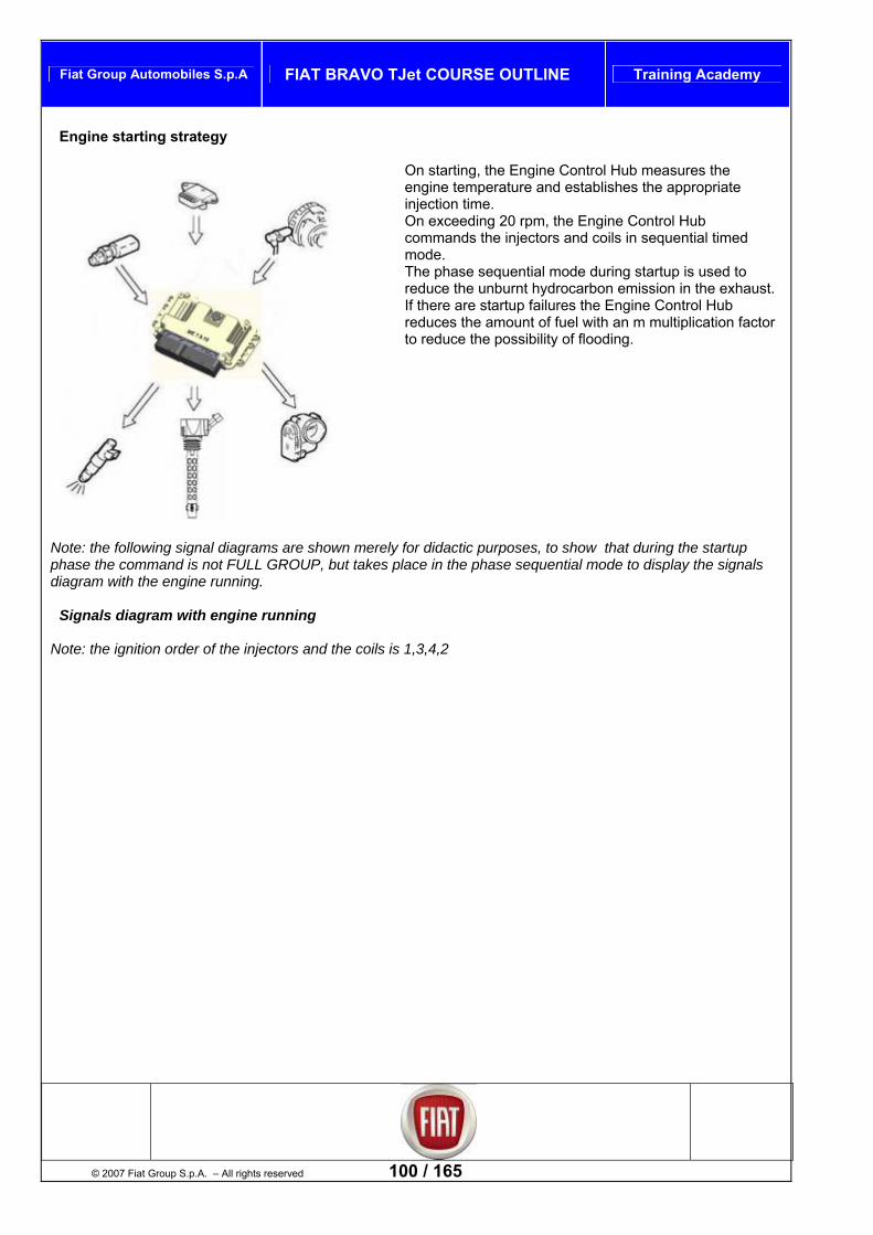
Fiat Group Automobiles S.p.A FIAT BRAVO TJet COURSE OUTLINE Training Academy
Engine starting strategy
On starting, the Engine Control Hub measures the
eding 20 rpm, the Engine Control Hub d
mode. The phase sequential mode during startup is used to reduce the unburnt hydrocarbon emission in the exhaust. If there are startup failures the Engine Control Hub reduces the amount of fuel with an m multiplication factor to reduce the possibility of flooding.
Note: the following signal diagrams are shown merely for didactic purposes, to show that during the startup phase the command is not FULL GROUP, but takes place in the phase sequential mode to display the signals diagram with the engine running.
Signals diagram with engine running
Note: the ignition order of the injectors and the coils is 1,3,4,2
engine temperature and establishes the appropriate injection time. On exce
© 2007 Fiat Group S.p.A. – All rights reserved 100 / 165
commands the injectors and coils in sequential time

Fiat Group Automobiles S.p.A FIAT BRAVO TJet COURSE OUTLINE Training Academy
101 / 165 © 2007 Fiat Group S.p.A. - All rights reserved

Fiat Group Automobiles S.p.A FIAT BRAVO TJet COURSE OUTLINE Training Academy
Signals diagram with engine started
Key RPM rev signal Timing signal phase V_INJ1 injector one command V_INJ3 injector three command V_INJ4 injector four command V_INJ2 injector two command V_BOB1 coil one command V_BOB3 coil three command V_BOB4 coil four command V_BOB2 coil two command
© 2007 Fiat Group S.p.A. – All rights reserved 102 / 165

Fiat Group Automobiles S.p.A FIAT BRAVO TJet COURSE OUTLINE Training Academy
Cold starting control
In cold starting conditions there is: A natural impoverishment of the mixture (due to
turbulence of the fuel particles at low temperatures) Reduced fuel evapo
poor
ration ternal walls of the
ntrol hub recognises this condition and
Intake air temperature
an be calibrated (from about 15 °C to about -25 °C).
e easier. Engine speed is decreased proportionally to the increase in engine temperature until reaching the nominal value with engine fully warmed up.
orque control
Condensation of the fuel on the inintake manifold
Greater viscosity of the engine oil. The engine cocorrects injection time based on:
Engine coolant temperature
Battery voltage Engine speed.
Ignition advance is exclusively a function of engine revs and engine coolant temperature. The “multi-spark” mode is enabled below a threshold that c
This strategy works by commanding the coils to give a number of sparks in close succession and it makes the combustion of the mixtur
T
To manage the various strategies the Engine Control Hub is m rque control. T e as fo
m ration at high loads, i.e. when the of
ngine revs.
Tthe Engine Control Hub picks up the torque request from the uv and then acts on the spark advances at th t mes. T ables for calculating engine torque, h
Low load calculation table High load calculation table Reverse gear calculation table.
For the versions with SPORT function, another three tables are taken into consideration, and these are: Low load calculation table with SPORT function enabled High load calculation table with SPORT function enabled Reverse gear calculation table with SPORT function enabled
ainly based on the principle of toher are two torque generation laws, which can be defined
llows: echanical torque gene
throttle read is greater than the full load throttle (95%the load) calculated on the basis of the e
Controlled torque generation (when the mixture strength control is active).
he controlled type occurs when:
ser through the accelerator pedal. The ECH then makes arious calculations rot le opening and the injection tihere are three main t
t
103 / 165 © 2007 Fiat Group S.p.A. - All rights reserved
ese being:

Fiat Group Automobiles S.p.A FIAT BRAVO TJet COURSE OUTLINE Training Academy
Driving torque evaluation The torque requested is generated by the engine and transmitted to the wheel through the transmission kinematic chain (clutch, gearbox, half-shafts, etcThe engine/transmission assembly is conseque erated from the combusi of the air-petrol mixtur , an
The angular speed of the crankshaft a The wheel angular speed and acceler gitudinal speed and
acceleration. Example of kinematic chain
.) ntly taken to be a system that inputs torque that is gend outputs a series of kinematic values such as: nd flywheel. ation related proportionally to the lon
on e
Key
1. Engine 2. Gearbox 3. Hub 4. Vehicle inertia/asphalt 5. Tyre wall 6. Flexible coupling 7. Wheel blocks 8. Slips 9. Half shafts
Torque generation by the engine can be divided into two different modes:
Rapid torque generation, only the spark advance changes. Slow torque generation, the throttle opening angle is changed.
Note: the rapid torque control is generall vated first. Torque generation immediately results in an increase in vehicle acceleration, which reaches the new steady operating value only after a series of oscillations that cause the user some discomfort (lengthwise shaking of the vehicle). The aim of the “DRIVEABILITY” strategies is to reduce this lengthwise shaking, without however introducing excessive delay between the request for torque and its actual generation.
© 2007 Fiat Group S.p.A. – All rights reserved 104 / 165
y acti

Fiat Group Automobiles S.p.A FIAT BRAVO TJet COURSE OUTLINE Training Academy
The system can be illustrated with a block diagram as in the figure given below, where a request for cceleration/deceleration from the user or from the functions inside the Engine Control Hub is first translated to a request for torque, and then into a rapid o
Once the rapid torque has been converted it w e slow rque will be used to define the throttle angle.
ated amount of air taken in permits thconsequently the injector opening time. A model for engine torque management.
ain r slow torque request.
ill be translated into a spark advance value, whereas th
e Engine Control Hub to calculate the amount of petrol, and toThe estim
Internal torque demand Engine startup Engine idle control Engine revs limiting Engine protection
Torquecoordin Coordination of request and efficiereque
request ator
ncy of torque st
Torque
Injection time
Individual fuel cut-
Waste Gate control
Torque off
Ignition advance
External torque demand Driver Cruise control Vehicle speed limiter ESP/ASR Driveability
Throttle angle
105 / 165
Torque conversion Generation of desired torque
Request efficie Engine startu Catalytic conv En
ncy p erter heating
gine idle control
© 2007 Fiat Group S.p.A. - All rights reserved

Fiat Group Automobiles S.p.A FIAT BRAVO TJet COURSE OUTLINE Training Academy
Injection time regulation
The Engine Control Hub calculates the opening time for the
the engine parameters – number of
, the “injection start” occurs at the optimal injection point, while the
ns fixed. The air rate of flow is calculated bearing in mind the following parameters.
the pressure measured in the intake manifolds the air temperature in the intake manifolds
Plus the following information that is used to correct the air ow calculation:
Pressure measured by the turbo pressure sensor Environmental pressure measured by the sensor in
the Engine Control Hub.
Engi d
electro-injectors and commands them with great speed and accuracy according torevs and air rate of flow – determined by the torque request. Since injection is sequential and timed for each cylinder
“end of injection” remai
rate of fl
ne i le speed control
The engine control hub recognises the engine idling condition through the “released” position of the accelerator
ed and the brake – clutch pedal signals, pilots the position of the motorised throttle valve.
.
Electrical balance The Engine Control Hub actuates electrical balance
d with a derivative greater sed
(ramp).
© 2007 Fiat Group S.p.A. – All rights reserved 106 / 165
pedal. To control idle speed, the engine control hub, according to the utilities being us
The foreseen idle speed with engine warm is 750 ± 50 rpm
strategies, considering battery load. When the battery voltage is reducethan a calibrated threshold, the target idle is increa

Fiat Group Automobiles S.p.A FIAT BRAVO TJet COURSE OUTLINE Training Academy
Enrichment control in acceleration
fuel supplied to the engine (to obtain
ing components:
TDC sensor
Engine coolant temperature, throttle aperture Pressure increase in the intake manifold
e losed, the engine control hub re-opens
re with e
Fuel cut-off on release (CUT-OFF)
In this phase the engine control hub adequately increases the quantity ofmaximum torque) according to the signals arriving from thefollow
Accelerator pedal potentiometer Revs and
The base injection time is multiplied by a coefficient according to:
If the abrupt change in injection time is calculated when thinjector is already cthe injector (extra pulse) in order to compensate the titmaximum rapidity. Successive injections will instead bincreased on the basis of the aforementioned coefficients.
Note: in controlling ASR and ESP the Engine Control Hub has to reduce injection times and act on the throttle and ignition advance times.
ined engine speed threshold, the engine control
gear, and at 1000 rpm in the other gears both for 120 and 150 HP versions.
according to vehicle travelling conditions. Before reaching idle speed, engine deceleration is verified. If greater than a certain value, fuel supply is partially restored to provide a “gentle deceleration” down to idle speed. The thresholds for reopening fuel supply and for fuel cut-off vary according to:
Engine coolant temperature Vehicle speed Engine revs.
107 / 165 © 2007 Fiat Group S.p.A. - All rights reserved
When the accelerator is released and beyond a certain predetermhub:
Cuts-off fuel to the injectors Reactivates fuel supply to the injectors at 1200 in 1st
Without fuel, engine speed drops more or less rapidly

Fiat Group Automobiles S.p.A FIAT BRAVO TJet COURSE OUTLINE Training Academy
Vehicle driveability strategy
a rapid torque control, which acts on the spark advances, and
if this is not sufficient, a slow torque control that acts on the
The driveability strategies include all the actions that the carries out in order to make the
e, caused during transients, more gentle and progressive, so that driving the vehicle becomes as pleasant as possible. Note: in this case the term transients is intended to mean the accelerations and decelerations that may be more or less sharp due to the pressing of the acceleration pedal and the
edal sensor
DOWN. Depending on the situation, the Engine Control Hub then sets
ance regulation
Engine Control Hublengthwise shaking of the vehicl
changes in gear. The Engine Control Hub recognises the acceleration and deceleration transients through the following:
The accelerator p The clutch and brake pedal switches
It then intervenes on the management of the torque, and adapts it with the calculation modules called TIP-UP and TIP-
throttle opening and consequently on the injection times.
Ignition adv
© 2007 Fiat Group S.p.A. – All rights reserved 108 / 165
Through the map memorised in its internal memory, the engine control hub is able to calculate ignition advance according to:
Engine load (idle, partial, full, according to revs and air flow-rate)
Intake air temperature Engine coolant temperature.
It is possible to selectively retard ignition at the cylinder requiring it, which is recognised by the combination of the value recorded by the rpm sensor and the "timing" data.

Fiat Group Automobiles S.p.A FIAT BRAVO TJet COURSE OUTLINE Training Academy
Pinging control
The engine control hub detects the presence of pinging (headknock) by processing the signal from t
he corresponding
nThe b continually compares the signals from
upd o take account of background noise and engine
r, and
advance is gradually restored up to the base value (in 0.8° steps) In acceleration, a higher threshold is applied, to take account of the increased noise of the engine in these conditions. The pinging control logic is also provided with a self-adapting function, which memorises the reductions to the advance that should be continually repeated, such as to adapt the map to the various conditions the motor finds itself in.
Turbocharge control
se sor. engine control hu
the sensor with a threshold value, which is in turn continually ated t
ageing. The engine control hub is thus able to detect the presence ofpinging (or incipient pinging) in each individual cylindereduces ignition advance for the cylinder concerned (in 3° steps up to a maximum of 6°) until this phenomenon ceases. Afterwards, ignition
Turbo pressure control The control unit directly control engine torque, considering turbocharging as well, directly piloting the waste-gate actuator on the turbocompressor group so as to reach an mapped targpressure in the intake ducts, based on:
et
ric pressure
calculated th he flow of way a
negative feedback action is introduced that assures system stability (intrinsically unstable). Based on the required boost pressure, the power necessary for the compressor to achieve it is calculated. This power has to be delivered by the turbine. The exhaust gas flow is modulated to assure that power is reached.
Dump valve control In systems with turbocompressor, when the throttle is suddenly closed, overpressure is generated in the ducts upstream of the throttle, that tend to slow the compressor impeller and cause strong vibration and noise. The dump valve recirculates the air from downstream to upstream of the compressor, reducing pressure in the duct. The engine control hub directly controls duct pressure, commanding the dump valve actuator according to:
Engine point Atmospheric pressure Turbo pressure
engine point atmosphe turbo pressure
In particular, when the desired boost pressure exceeds a reshold, the ECH begins to modulate t
109 / 165 © 2007 Fiat Group S.p.A. - All rights reserved
exhaust gas on the turbine through the waste gate. In this

Fiat Group Automobiles S.p.A FIAT BRAVO TJet COURSE OUTLINE Training Academy
© 2007 Fiat Group S.p.A. – All rights reserved 110 / 165
Normal / Sport (overboost) control (150 HP version only) ressing the Normal/Sport button, in addition to changing the power steering settings, softer at low speed and arder at high speed, the Overboost function is als
The Normal/Sport button is connected by a discret rt and normal state information is rendered available to the ECHTo control the Overboost function, the ECH mainly osition of the accelerator pedal and acts consequentially on the waste gate electrovalve, re ulating turbocompressor pressure and acting on the aperture logic of the motorised throttle valve. The following are the salient features of the Norma Normal mode enabled
Maximum torque 206 Nm Maximum power 150 HP Driveability strategy “Soft” Limited fuel consumption for high engine
Sport mode enabled
Maximum torque 230 Nm Maximum power 150 HP Sports driving strategy Higher consumption at high engine loads
oost specifications The overboost is set for a maximum torque increa .
ort button) are defined by the position of the accelerator pedal, (torque request aximum time of 80s,
ould not be taken to mean a pressure that damages the turbine, but as the possibility to
ure recovery tween the target pressure and the pressure measured is greater than 200 mbar during the
erator pedal or on the throttle actuator, the turbo pressure is limited.
o protect the turbine, the Engine Control Hub checks the temperature of the exhaust gases against a mapped , since an excessive increase in the temperature could damage it.
Ph o enabled.
e line to the Power Steering Hub, so the Spo via C-CAN network. considers the pg
l and Sport functions
loads
Overb
se up to 230 NmThe overboost conditions (spfrom user), equal to the maximum value for a m Note: overboost shhave a pressure greater than the maximum at that moment. Turbo pressIf the difference beincrease in turbo pressure in the acceleration transients, then the throttle is closed. If there is an error on the accel Tcalculation model

Fiat Group Automobiles S.p.A FIAT BRAVO TJet COURSE OUTLINE Training Academy
Engi
ne speed limiter
g engine torque First the Engine Control Hub cuts fuel by changing injection times. If this is not sufficient, the Engine Control Hub closes the throttle valve.
imum engine speed for the 120 HP version is 6350 it is 6500 rpm.
Combustion control – Lambda probe
The control unit controls the maximum engine speed, limitin
The maxrpm, whereas for the 150 HP version
111 / 165 © 2007 Fiat Group S.p.A. - All rights reserved
post catalytic converter probe).
InscT the titre d st
TitIn s to recover both production dispersion and the hysteresis derived from the response of the pre-converter probe due to ageing
control (closed loop of
EOBD systems the lambda probes, which are all of the ame type, are installed upstream and downstream of the atalytic converter.
e pre-converter probe determines control ofhenominated 1 loop (closed loop of upstream probe). he post-converter probe is used to diagnose the converter self and to fine tune the control parameters of the 1st loop. this context the adaptiveness of the second loop serve
and pollutant build-up. trol is referred to as 2This con nd loop
The check on the first loop is enabled when the upstream lambda probe is able to provide a reliable signal, which occurs some time after the engine has been started. Probe activation time depends on the initial engine temperature. The second loop check is enabled after much longer than the first loop, for example: if the first loop check occurs 80 seconds after engine startup, the second loop check will take place after 450 seconds. Note: the probe voltage downstream is about 630mV and is constant (if it begins to oscillate it means that the catalytic converter has deteriorated).

Fiat Group Automobiles S.p.A FIAT BRAVO TJet COURSE OUTLINE Training Academy
Fuel injection time correction strategy.
Calculation of the K correction parameter of the fuel injection time. Key V lambda probe voltage G rich range M lean range
correction parameter
hat only takes into consideration the ch/lean and lean/rich changes in the probe voltage. his control strategy then produces an alternative probe voltage pattern. he calculation strategy of the K parameter is a compromise between the need to keep the strength variation ss than 3% and the need to obtain a high oscillation frequency in the probe voltage. Frequencies of about 2
Hz in fact are obtained due to the fact that the strength is varied by more than 3% in the attempt to obtain better results. Note: positioning the probe as close as possible to the combustion chamber results in a better oscillation frequency for the probe voltage. Note: the Engine Control Hub runs the diagnosis on the lambda probe on the basis of the lambda voltage, lean rich peak value, and rise time and fall time switching.
© 2007 Fiat Group S.p.A. – All rights reserved 112 / 165
KA;B;C;D variation points In order to reduce pollutant emissions, the Air/Fuel ratio of the mixture feeding the engine is controlled by a parameter called K, which alters the fuel injection time.
his parameter is calculated using a suitable algorithm by a control unit tTriTTle

Fiat Group Automobiles S.p.A FIAT BRAVO TJet COURSE OUTLINE Training Academy
Radiator cooling fan control
The Engfan acco
Fa5°
Fa5°
There is er control (linear pressure sensor signal) that act e coolant sure with the conditioning system on. In the acontrol he error is
C n
ine Control Hub commands activation of the radiator rding to coolant temperature: n speed 1 activation at 97°C with hysterisis of about C n speed 2 activation at 102°C with hysterisis of about C then a furth
ivates the fan at speed 1 or speed 2, according to thgas presbsence of the coolant fluid temperature signal, the unit actuates recovery by activating fan speed 2 until teliminated.
on ection with the air-conditioning system
The air conditioner is always managed together with the torque que is added to the conditionr-
requested torque and if the result is less than a threshold set in relation to the engine revs, conditioner operation is enabled. If however the result is greater than a threshold set in relation to
kph, then conditioner operation is disabled. power to the
compressor: During starting
During pick-up with accelerator pressed fully down.
control. The user-requested tor
the engine revs and the speed is less than a minimum of 10
The engine control hub momentarily interrupts
113 / 165 © 2007 Fiat Group S.p.A. - All rights reserved
Deactivating it with engine temperature > 115°C and is reactivating with a hysterisis of 5.3°C

Fiat Group Automobiles S.p.A FIAT BRAVO TJet COURSE OUTLINE Training Academy
Cr
uise Control
Bring the vehicle to the required speed; note that Cruise Control can only be enabled for speeds over 40 kph. It is advisable to enable it in 4
managed by the
Note: vehicle speed information is obtained from the C-
Memorising a chosen speed To enable Cruise Control, proceed as follows: Turn the two-position ring switch to ON;
speed to be safely maintained.
steady
uise Control state.
hanging a speed setting
Sp dPush tOn ethe h
stem will maintain the vehicle at the new speed. The Cruise Control can function throughout the entire range of possible engine speeds. Resume button By pressing the corresponding button, this function returns the vehicle to the last memorised speed, if for particular conditions (example, pressing brake or clutch pedals) the cruise control has been disabled. Disattivazione del cruise control Disabling cruise control Cruise Control can be disabled by the driver by:
turning the ring switch to OFF switching off engine; pressing the brake or clutch pedal (in these cases the last speed reached is saved, and can be
resumed by pressing the resume button) vehicle speed lower than allowed (approx 40 kph) or greater than permitted maximum;
If the stick is used without the clutch pedal, coherence is lost between engine revs and vehicle speed. In all these cases pressing the resume button will enable the system again. Pressing the accelerator with Cruise Control enabled: pressing the accelerator (example, overtaking) the Cruise Control permits a temporary increase in speed since it disables itself temporarily, but as soon as the accelerator pedal is released the system resumes the set speed. Recognition of the gear engaged is achieved through comparison of vehicle speed and engine speed with clutch engaged. Cruise Control is automatically disabled if:
The cruise control system is entirely Engine Control Hub in the following modes.
CAN network.
th gear or upwards and in road conditions that allow thePush the control stick upward to increase speed (stick withautomatic return spring, not stable) Release the accelerator pedal and allow the system to runthe vehicle; On the instrument panel, the warning light lights according to the signal from the Engine Control Hub, through the CAN network, indicating CrThe warning light goes out when the system disablescruise control.
CProceed as follows to change speed settings:
ee increase: he stick upwards. This generates an acceleration ramp with constant programmable gradient;
rel asing the lever (automatic return), the system maintains and memorises the new speed reached by ve icle.
© 2007 Fiat Group S.p.A. – All rights reserved 114 / 165
Sped reduction: Push the lever downwards. Having reach the required speed, release the stick and the sy

Fiat Group Automobiles S.p.A FIAT BRAVO TJet COURSE OUTLINE Training Academy
acceleration is greater than calibrated maximum (example, rapid descent); set maximum (using gear lever without clutch pedal).
The sy se control automatically if any signals used by cruise control logic are
clutch switch plausibility; Cruise switch and Resum bility; Cruise switch plausibility and position of speed increase or decrease stick.
ntrol system
deceleration greater thanstem in any case disables crui
incorrect due to component faults: vehicle speed sensor; accelerator pedal potentiometer; brake switch plausibility;
e button plausi
Emissions co
115 / 165 © 2007 Fiat Group S.p.A. - All rights reserved
The emissions control system includes devices designed to reduce toxic emissions into the atmosphere.
tant emissions caused by the vehicle are: Exhaust emissions
ur/gas emissions from the engine block r emissions from the fuel su
Exhaust emissions are limited by means of a trivalent
anaged by two Lambda probes, the upstream one for obtaining the optimal stoic tric ratios
performance, and the do stream one ee EOBD strategies).
To ensure that the catalytic converter functions correctly for a long time, the Engine Control Hub check rature of
st gases using a mapped calculation model.
e vapour recovery system ntrolled by the Engine Control Hub.
aged by the antievaporation system, a system fitted with ntrolled by the Engine Control Hub.
turated and nding the hen the outside
, it uses the vacuum in the intake manifold to draw in fresh air from the outside through intake manifold where they are aspirated by the
rength that is compensated for by the cont re s
shing. ns:
place periodically.
e of operation with throttle partially open.
rban sub-cycle for the whole EUDC cycle
The major pollu
Vapo Fuel vapou pply circuit
catalytic converter, mhiome
wnto improve catalyser to control efficiency, (s
s the tempethe exhau
The crankcase vapour/gas emissions are controlled by thNote: system not coFuel vapour emissions from the supply circuit are manan electrovalve coThe canister valve is used to wash the active carbon filter to prevent it becoming sahydrocarbons (fuel vapours) that form in the tank, into the atmosphere, especially wtemperature is high or during shaking of the vehicle.
se
When the valve opensthe filter, collect the petrol vapours and take them to theengine. This operation results in a variation of the mixture st rol unit (mixtutrength control).
The adaptive parameters are deactivated during canister waCANISTER washing takes place under the following conditio
At idle: washing takes Under certain engine conditions, with throttle partially open
ave been used as an examplThe NEDC areas h
On the third ramp of the 1st urban sub-cycle On the second and third ramp of the 2nd u Pratically

Fiat Group Automobiles S.p.A FIAT BRAVO TJet COURSE OUTLINE Training Academy
Washing is inhibited during gearch off for the whole cycle.
anges and cut-
© 2007 Fiat Group S.p.A. – All rights reserved 116 / 165
The figure shows acquisition of the “canister valve target opening “ variable (in red)“vehicle speed” (white variable) is also shown to identify the cycle areas. More consistent w
on a NEDC cycle. The
ashing obviously occurs with valve opening at 100%.

Fiat Group Automobiles S.p.A FIAT BRAVO TJet COURSE OUTLINE Training Academy
Self-diagnosis and recovery
117 / 165 © 2007 Fiat Group S.p.A. - All rights reserved
Engine starting fault indications:
if the warning light does not go out after starting the engine, this indicates pin the engine control hub
Fault indications during operation:
The engine control hub self diagn ntrols the correct function of the system a ny
g light (mil) he control ard colour and ideogram.
This warning light indicates both engine control faults and problems detected by the EOB strategies.
arning light (mil) is as
With key to RUN the light comes on ns on until the engine effectively starts. T ontrol hub self-diagnosis system checks the signals from the sensors comparing them with the permi es.
resence of a fault memorised
cates possible damage to the catalytic converter due to misfiring. lts or EOBD diagnose
the engine control hub defines the type of recovery for each fault, according to whic is faulty.
g correctly. t can be actuated by the Engine Control Hub are:
throttle body error Limp home after accelerator pedal error Turbocharge:
o pressure increase in acceleration transients if the difference (target) 00mbar e closes.
If there is an accelerator pedal or throttle actuator error turbo pressure is limited
EOBD ConSince 1970, in Europe there has been a standard for autovehicle emissions (EC Directiv over
as undergone repeated updating, the most recent being in Octob directive 98/69).
as established the initial requirements for approving EOBD systems, defi as a of identifying the zone in f a comput he system
trument panel (called Malfunction Indicator, MI) which indicates to the driver the vehicle to produce a greater quantity of pollutan s than
permitted by law. Acco stem must undergo a series of approval tests by the auth g with
vehicles in current use, sampled by the approval authority. For approval purposes, the vehicle with a representative age of 80,000 km, undergoes a tes average
rocarbon (HC) and nitrogen oxide (Nox) emissions. ducted ing cycle (NEDC cycle). ses o
Fuel supply system (fuel system diagnosis) Lambda probe diagnosis Catalytic converter diagnosis
osis system cond indicates a
faults by means of a warninpanel, with European stand
on t
D diagnosis
The functional logic of the wfollows.
and remaihe engine c
tted limit valu
flashing light indi light on steady indicates presence of engine management fau d faults.
h component
The recovery parameters are managed by the components still functioninThe recovery strategies tha
Limp home after
During turbthe throttl
-(read)>2
.
trols e 70/220) which
the course of the years h er 1998 (EC
Directive EC 98/69 hsystem as an electro
ning EOBDnic on board diagnosis system for emissions control, capable
which a fault has probably occurred, by means of codes entered into the memory oincludes a warning light on the ins
er. T
the presence of faults that could cause t emission
rding to the standard, this sytests on those installed on
orities, alon
t to verifycarbon monoxide (CO), unburned hyd The test, conin the laboratory on dynamometric benches, consists of executing a standard runnEuropean standards require that the EOBD system carries out at least four diagnosubsystems with a direct impact on emissions:
n the engine

Fiat Group Automobiles S.p.A FIAT BRAVO TJet COURSE OUTLINE Training Academy
Diagnosis of irregular ignitio nosis) that prevents correct converter func xtreme cases leading to irreversible
In detail: Fuel system diagnosis serves to detect any malfunctions in the fuel supply line. Lambda probe diagnosis to reveal the behaviour of the probes upstream and downstre f the
ison with certain quantities and corresponding thresholds. h indire asurement
s capacity to store oxygen. to detect misfiring with destructive effect on catalytic converte
n (misfire diag damage.
tion, in e
am oconverter, by compar
Converter diagnosis serves to measure the degradation of the converter througof it
ct me
Misfire analysis serves r and non-destructive effect, but that lead to high pollutant emissions.
System self-adaptation
with a unction erves to recognise changes that take e
due to settlement over time and ageing both nts and the engine as a whole. These changes are memorised in the form of modifications to the base maps, and serve to adapt system function to the progressive alteration of the engine and its com nts with respect to their characteristics when new. The self-adapting function also allows the encompensate for inevitable differences (due to prod on tolerance) in any substituted components. From analysing the exhaust gas, the engine modifies the base map with respect to the cha tics of the engine as new.
ntrol Hub implements the following self-adaptation strategies:
Multiplicative coefficient of the mixture strength control (FRA). It takes into accounength related to the derivatives of the probes, injectors and intake manifold (seepage). It
tion (when the strength control is active). ngth control (ORA). Corrects any leaks from the inje It updates
itself at idle. arameters are not cancelled if the battery is disconnected.
© 2007 Fiat Group S.p.A. – All rights reserved 118 / 165
The engine control hub is equipped that s
self-adapting f place in the engin
of the compone
pone
gine to ucti
control hubracteris
In detail, the Engine Cot the variations in the
mixture strupdates itself during vehicle opera
Additive coefficient of mixture stre ctors.
The self-adapting p

Fiat Group Automobiles S.p.A FIAT BRAVO TJet COURSE OUTLINE Training Academy
Electronic diagnosis Introduc
rs and corresponding helps (if available), the l h codes and MIL warning lights activation modes, and the list of active th
miner diagnosis.
tion This chapter contains lists of the paramete ist of errors witcorresponding DTC diagnoses wicorresponding helps available in the Exa
Description Unit of easurement/ Status value
ODOMETER Indicates the kilometres travelled by the vehicle.
Km
NUMBER OF OUT OF REVS engine has gone out of revs. Indicates the number of times the
-
MAX OPER. CONDIT. TIME COUNTER: Indicates for how long the engine has run at maximum speed
msec
MAXIMUM ENGINE SPEED Rpm NUMBER OF PROGRAMMINGS
r of times the control unit has been programmed Indicates the numbe-
ODOMETER LAST PROGRAMMING ntrol unit was last programmed. Indicates the kilometres when the co
Km
ENGINE REVS Indicates the engine rotation speed
Rpm
TEMPERATURA ACQUA Indicates the temperature of the engine coolant.
Deg./Cent
AIR TEMPERATURE Indicates the temperature of the air taken into the intake manifold.
Deg./Cent
SPARK ADVANCE Indicates the advance value assigned by the control unit, therefore the
e is not taken into consideration mechanical keying valu
Deg./Ang.
INJECTION TIME Indicates the opening time of the injector or injectors
Msec
ENGINE LOAD Indicates in % the volumetric engine load (independently from engine
linders) displacement and number of cy
%
THROTTLE ANGLE Indicates the angular position of the motorised throttle
%
AIR RATE OF FLOW Indicates the amount of air taken in by the engine.
Kg/h
BATTERY VOLTAGE Indicates the value of the control unit power supply voltage
Volt
VEHICLE SPEED (from CAN) Is the vehicle speed coming from the ABS control unit through CAN line
Kph
LAMBDA 1 VOLTAGE UPSTREAM OF CAT. Help not available
mv
LAM
119 / 165 © 2007 Fiat Group S.p.A. - All rights reserved
BDA 1 VOLTAGE DOWNSTREAM OF CAT. Help not available
mv
TARGET ENGINE IDLE REVS Rpm

Fiat Group Automobiles S.p.A FIAT BRAVO TJet COURSE OUTLINE Training Academy
Description Unit of easurement/ Status value
Indicates the engine revs calculated by the control control unit to which the idle refers. ANTIIndicates the opening percentage of the anti-evapo
% -EVAP. VALVE OPENING ration valve.
ACCELERATOR POSIT. TRACK 1 s of the accelerator p al track 1.
Volt Indicate the percentage value otentiometer signACCELER 2 Indicates the percentage value of the accelerator p
Volt ATOR POSIT. TRACK otentiometer signal track 2.
ACCELERIndicates in of the potentiometer.
% ATOR PEDAL POSITION percentage the position pedal measured by the
LAMBDA PROBE INTEGRATOR This is the correction made by the control unit on l needed to
e
- the amount of fue
reach th correct air/petrol ratio. AD/C EXHAUST GAS TEMPERATURE mv FACTOR - BETWEEN (high loads) FACTOR BETWEEN (low loads) - FACTOR BETWEEN 1 and 2 (CURRENT LOAD)
a t of panufacturing tolerances of air flow meter/lambda
- Multiplic tion correction factor of the amoun etrol injected. Recovers the m probe/injectors DTV 1 FACTOR Addition co of pe
tu eter/lambdengine is idling.
- rrection factor of the amount
ring tolerances of air flow mtrol injected. Recovers the
manufac a probe/injectors when the
TURBO ACTUATOR COMMAND s of the Wast and
% Indicate the % value of the Duty cycle egate valve commDTV 2 FACTOR Addition correction factor of the amount of pe covers the manufacturing tolerances of air flow meter/lambdengine is idling.
- trol injected. Rea probe/injectors when the
THROTTLIndicates the point reached in the learn procedu r limit
h d the is complete when it reaches 7, otherwise it is not complete or h e correctly.
- E LEARN PHASE re of the throttle lowe
value. T e value ranges between 0 and 7, an learn procedureas not taken plac
INTAKE PRESSURE Indicates the fold
MBar pressure in the intake mani
ATMOSPIndicates the value read by the pressure sensor.
Mbar HERIC PRESSURE
TURBO PRESSURE MEASURED Indicates the pressure read in the turbo pressure ci
MBar rcuit.
TARGET Indicates the pressure value calculated by the cont
MBar TURBO PRESSURE rol unit.
AD/C TURBO PRESSURE lt
MVolt Is the vo age value read directly on the sensor. ENGINE TONo help available
%
© 2007 Fiat Group S.p.A. – All rights reserved 120 / 165
RQUE (MEASURED)

Fiat Group Automobiles S.p.A FIAT BRAVO TJet COURSE OUTLINE Training Academy
Description Unit of easurement/ Status value
ENGINE TOIndicates the toreque requested by the control be the engine control unit.
% RQUE (TARGET): ing examined by
EXHAUST GAS TEMPERATURE Deg./Cent CLOSED THROTTLE AIR FLOW RATE The air flow rate through the air flow meter when th the position of
.
Kg/h e throttle is in
maximum mechanical closureEND OF INJECTION ANGLE Help not available
Deg./Ang.
ECU SERIA - L NUMBER OVERBOThe amount of time in overpressure on values that sholds are associated to the turbo, minimum and maximum. Once the minimum
d enes. eded the co
remains for too long in OVERBOOST (over the maxs ene.
Minutes OST COUNTER are too high. Two thre
thresholincrease
has been exceeded, the turbo intervOnce the maximum threshold is exce
and the counter does not unter increases. If it
. threshold) the diagnosis strategie associated with the turbo interv
Allowed ENGINE STARTUP ion control unit permits Not allowIndicates whether the inject engine startup ed
Programmed INJECTION CONTROL UNIT trol unit is progra Not programIndicates whether the injection con mmed. med
Received Not received
UNIVERSAL CODE
Not enabled Present DEDICATED LINE
Not present Requested SET CRU
Not requesISE DEC.(-)
ted Requested SET CRU
Not requested ISE ACC (+)
ON CRO n 'On', permits the cru
to be maintained automatically. Off
UISE SWITCH Can be ' n' or 'Off' and, whe ising speed set by the driver
Pressed CRUISE R TON (RCL) Release
ESTORE BUTd
Present CRUISE CAbsen
ONTROL t
No request Cruise restore button (RCL)
Set Cruise d(-)
121 / 165 © 2007 Fiat Group S.p.A. - All rights reserved
eceler
REQUES E LEVER Indicates the request assumed by the cruise lever
deceler (-),Set Cruise dec
Set Cruise deceler
T FROM CRUIS (No request, Cruise restore
button (RCL), Set Cruise eler (+)

Fiat Group Automobiles S.p.A FIAT BRAVO TJet COURSE OUTLINE Training Academy
Description Unit of easurement/ Status value
(+) ON OIL PRESSURE SWITCH
If 'ON' indicates that the oil pressure needed for n has been reached
Off engine operatio
Active TURBO VACUUM VALVE u intake duct upstre . May e
Not activThe vac um valve located in the am of the throttle bodybe Activ (open) or Not Active (closed).
e
Neutral/None First/reverse
Second Third
Fourth Fifth Sixth
SPEED GEAR USED Indicates the speed currently used by the gearbox f 'Reverse' and 'Neut c gearbox
Reverse
. The states oral' relate to vehicles with automati
Active COOLING FAN 1 s w speed Not activIndicate the fan is activated at lo e
Active COOLINGIndicates the fan is activated at high speed. Not active
FAN 2
Activated PINGINGDeactiva
CONTROL ted
Run Stop
KEY POSITION s sition.
During startup
Indicate the status of the key po
Pressed CLU H PEDAL s ion. Release
TCIndicate the clutch pedal posit d
Pressed BRAKE PEDAL Indicates whether the brake pedal is 'Pressed' or ‘R Pressed eleased’
Activated CONDITIndicate
. QUEST s activate the air conditioner tiva
ACTIVAT. REthe request to compressor Deac ted
Activated CONDITIndicate
IOs r command se t. Deactivated
NER COMPRESS. the status of the compresso nt from the control uni
Idle ENGINEIndicate
Ss Out of idle
TATUS the engine operating conditions.
Activated CUT-OFFs trol l cut-off. Deactiva
STATUS Indicate the release condition in which the con unit triggers a fue ted
Performed ENGINE H==
EATING
Closed Loop STATUS . Help not available Open Loop
© 2007 Fiat Group S.p.A. – All rights reserved 122 / 165
LAMBDA 1 UPSTREAM CAT

Fiat Group Automobiles S.p.A FIAT BRAVO TJet COURSE OUTLINE Training Academy
Description Unit of easurement/ Status value Closed Loop STAT STREAM CAT.
Help not available en LoUS LAMBDA 2 UP
Op op Active CATALY
The ‘AcT
tiv to alytic converter o ate
Not activIC CONVERT. 1 HEATING e' status indicates that the functions
operating temperature have been activbring the cat
quickly t d. e
Closed Loop STATUS Help not available Open Loop
LAMBDA 1 DOWNSTREAM CAT.
Closed Loop STATUS Help not available Open Loop
LAMBDA 2 DOWNSTREAM CAT.
Active ANTI-EVA‘A n ‘Active’ it drocarbon
vapours emitted from the tank. Not activ
PORATION VALVE May be ctive’ or ‘Not active’ and whe can recover the hy e
Present CONTRO . Absen
L UNIT POWER SUPPLYt
Present ANTI-SKIAbsent
D (ASR)
Present CATALYT Absen
IC CONVERTER 1t
Correct THROTTLIndicates whether the self-learn procedure of the torised
aNot correct
E LEARN RESULTS lower limit of the mo
throttle h s been terminated correctly Not allowed ..in progress
THROTTL ditions ar ' and te ccessfully).
Terminated
E LEARN May be'Termina
'Not allowed' when the cond' (if it has been completed su
e not, '...in progress
Active FUEL PUIndicates the activation status of the fuel pump relay Not active
MP RELAY
Learnt BRAKE Hence of ABS/VDC/ASR (only if connected RNT' by the
n
UB (NFR) The pres by CAN) is 'LEA Not learreceptio of at least one message on CAN
nt
None Cruise control
TYPE OF CRUISE PRESENT vehicle. e’ may only e uise cont
Adaptive (A
Indicates the type of cruise used on the The status ‘Nonoccur wh n the vehicle is not fitted with cr rol.
CC) Learnt AIR CONDITIONER CLIMATE CONTROL
Is automatically 'LEARNT' by the control unit at the activation of the climate control
Not learnt
Automatic Manual
Selespeed
TYPE OIndicates
F ESENT rbox used on the vehicle sible' status
y d on ve different types of gearbox, d selespeed
Not lear
GEARBOX PRthe type of gea . The 'Not plau
may onl occur after the ECU is exchangemanual an
hicles with
nt
123 / 165 © 2007 Fiat Group S.p.A. - All rights reserved
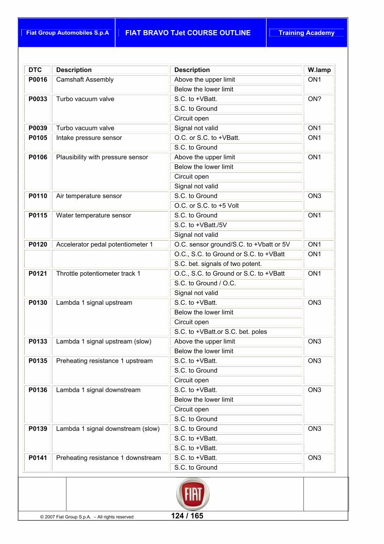
Fiat Group Automobiles S.p.A FIAT BRAVO TJet COURSE OUTLINE Training Academy
DTC Description Description W.lamp
Above the upper limit P0016 Camshaft Assembly Below the lower limit
ON1
S.C. to +VBatt. S.C. to Ground
P0033 Turbo vacuum valve
Circuit open
ON?
P0039 Turbo vacuum valve Signal not valid ON1 O.C. or S.C. to +VBatt. P0105 Intake pressure sensor S.C. to Ground
ON1
Above the upper limit Below the lower limit Circuit open
P0106 Plausibility with pressure sensor
Signal not valid
ON1
S.C. to Ground P0110 Air temperature sensor 5 Volt O.C. or S.C. to +
ON3
S.C. to Ground S.C. to +VBatt./5V
P0115 Water temperature sensor
Signal not valid
ON1
P0120 Accelerator pedal potentiometer 1 O.C. sensor ground/S.C. to +Vbatt or 5V ON1 O.C., S.C. to Ground or S.C. to +VBatt S.C. bet. signals of two potent.
ON1
O.C., S.C. to Ground or S.C. to +VBatt S.C. to Ground / O.C.
P0121 Throttle potentiometer track 1
Signal not valid
ON1
S.C. to +VBatt. Below the lower limit Circuit open
P0130 Lambda 1 signal upstream
S.C. to +VBatt.or S.C. bet. poles
ON3
Above the upper limit P0133 Lambda 1 signal upstream (slow) Below the lower limit
ON3
S.C. to +VBatt. S.C. to Ground
P0135 Preheating resistance 1 upstream
Circuit open
ON3
S.C. to +VBatt. Below the lower limit Circuit open
P0136 Lambda 1 signal downstream
S.C. to Ground
ON3
S.C. to Ground S.C. to +VBatt.
P0139 Lambda 1 signal downstream (slow)
S.C. to +VBatt.
ON3
S.C. to +VBatt. P0141 Preheating resistance 1 downstream
© 2007 Fiat Group S.p.A. – All rights reserved 124 / 165
S.C. to Ground ON3

Fiat Group Automobiles S.p.A FIAT BRAVO TJet COURSE OUTLINE Training Academy
DTC Description Description W.lamp Circuit open S.C. to +VBatt. S.C. to Ground
P0201 Injector cylinder 1
Circuit open
0N1
S.C. to +VBatt. S.C. to Ground
P0202 Injector cylinder 2
Circuit open
ON1
S.C. to +VBatt. S.C. to Ground
P0203 Injector cylinder 3
Circuit open
ON1
S.C. to +VBatt. S.C. to Ground
Injector cylinder 4 P0204
Circuit open
ON1
O.C. sensor ground/S.C. to +Vbatt or 5V P0220 Potentiometer 2 accelerator pedal O.C., S.C. to Ground or S.C. to +VBatt
ON1
O.C./S.C. to +Vbatt/5V P0221 Throttle potentiometer track 2 S.C. to Ground / O.C.
ON1
O.C. or S.C. to +VBatt. P0230 Fuel pump relay S.C. to Ground or final stages overheated
ON1
O.C. or S.C. to +VBatt. P0235 Turbo pressure sensor S.C. to Ground
ON3
Above the upper limit Below the lower limit No signal
P0236 Turbo pressure difference
Signal not valid
ON3
Above the upper limit P0240 Turbo pressure Below the lower limit
ON1
125 / 165 © 2007 Fiat Group S.p.A. - All rights reserved
Above the upper limit Below the lower limit
P0243 Overboost solenoid
Signal not valid
ON1
Danger of catal. overheating P0300 Misfiring (generic) Influence on emission values
ON3
Danger of catal. overheating P0301 Misfiring cyl.1 Influence on emission values
ON3 Blink
Danger of catal. overheating P0302 Misfiring cyl.2 Influence on emission values
ON3 Blink
Danger of catal. overheating P0303 Misfiring cyl.3 Influence on emission values
ON3 Blink
Danger of catal. overheating P0304 Misfiring cyl.4 Influence on emission values
ON3 Blink
Above the upper limit P0325 Knock control 1 O.C. or S.C.
OFF
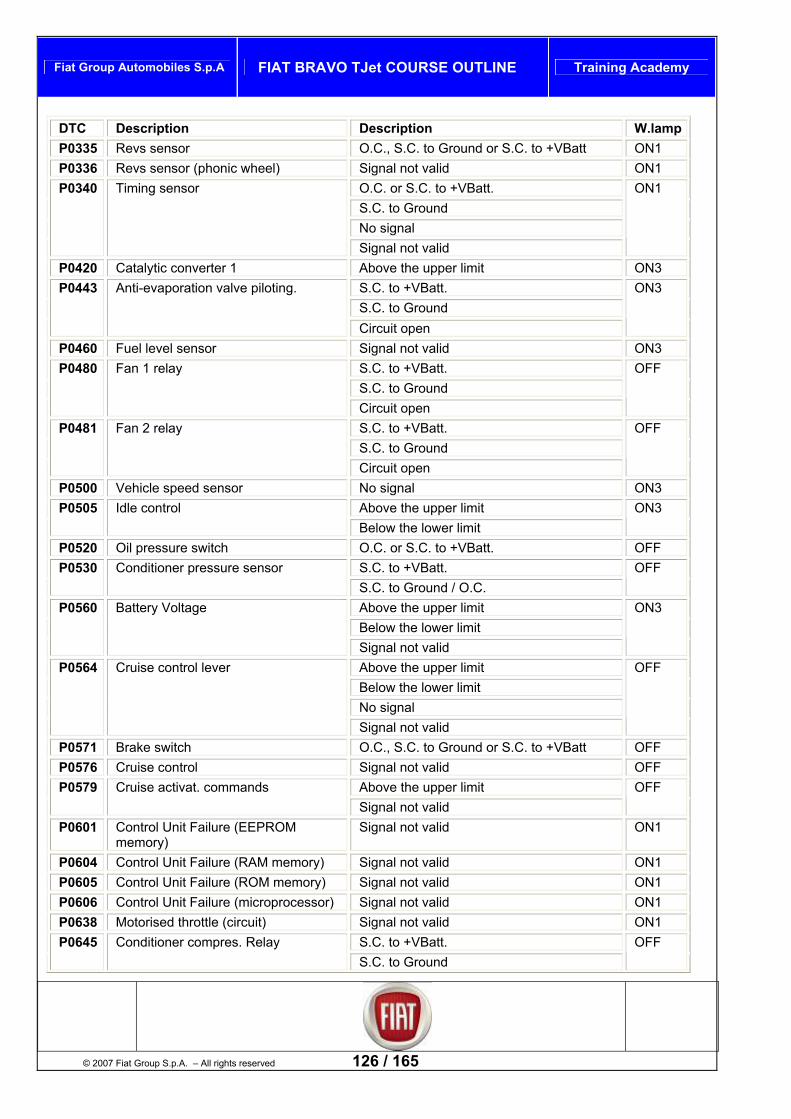
Fiat Group Automobiles S.p.A FIAT BRAVO TJet COURSE OUTLINE Training Academy
DTC Description Description W.lamp P0335 Revs sensor O.C., S.C. to Ground or S.C. to +VBatt ON1 P0336 Revs sensor (phonic wheel) Signal not valid ON1
O.C. or S.C. to +VBatt. S.C. to Ground No signal
P0340 Timing sensor
Signal not valid
ON1
P0420 Catalytic converter 1 Above the upper limit ON3 S.C. to +VBatt. S.C. to Ground
P0443 Anti-evaporation valve piloting.
Circuit open
ON3
P0460 Fuel level sensor Signal not valid ON3 S.C. to +VBatt. S.C. to Ground
P0480 Fan 1 relay
Circuit open
OFF
S.C. to +VBatt. S.C. to Ground
P0481 Fan 2 relay
Circuit open
OFF
P0500 Vehicle speed sensor No signal ON3 Above the upper limit P0505 Idle control Below the lower limit
ON3
P0520 Oil pressure switch O.C. or S.C. to +VBatt. OFF S.C. to +VBatt. P0530 Conditioner pressure sensor S.C. to Ground / O.C.
OFF
Above the upper limit Below the lower limit
P0560 Battery Voltage
Signal not valid
ON3
Above the upper limit Below the lower limit No signal
P0564 Cruise control lever
Signal not valid
OFF
P0571 Brake switch O.C., S.C. to Ground or S.C. to +VBatt OFF P0576 Cruise control Signal not valid OFF
Above the upper limit P0579 Cruise activat. commands Signal not valid
OFF
P0601 Control Unit Failure (EEPROM memory
Signal not )
valid ON1
P0604 Control Unit Failure (RAM memory) Signal not valid ON1 P0605 Control Unit Failure (ROM memory) Signal not valid ON1 P0606 Control Unit Failure (microprocessor) Signal not valid ON1 P0638 Motorised throttle (circuit) Signal not valid ON1
S.C. to +VBatt. P0645 Conditioner compres. Relay S.C. to G
© 2007 Fiat Group S.p.A. – All rights reserved 126 / 165
round OFF
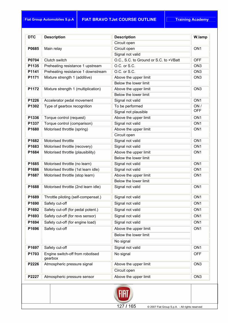
Fiat Group Automobiles S.p.A FIAT BRAVO TJet COURSE OUTLINE Training Academy
DTC Description Description W.lamp Circuit open Circuit open P0685 Main relay Signal not valid
ON1
P0704 Clutch switch O.C., S.C. to Ground or S.C. to +VBatt OFF P1135 Preheating resistance 1 upstream O.C. or S.C. ON3 P1141 Preheating resistance 1 downstream O.C. or S.C. ON3
Above the upper limit P1171 Mixture strength 1 (additive) Below the lower limit
ON3
Above the upper limit P1172 Mixture strength 1 (multiplication) Below the lower limit
ON3
P1226 Accelerator pedal movement Signal not valid ON1 To be performed P1302 Type of gearbox recognition Signal not plausible
ON / OFF
P1336 Torque control (request) Above the upper limit ON1 P1337 Torque control (comparison) Signal not valid ON1
Above the upper limit P1680 Motorised throttle (spring) Circuit open
ON1
P1682 Motorised throttle Signal not valid ON1 P1683 Motorised throttle (r ) ecovery Signal not valid ON1
Above the upper limit P1684 Motorised throttle (plausibility) Below the lower limit
ON1
P1685 Motorised throttle (no learn) Signal not valid ON1 P1686 Motorised throttle (1st learn idle) Signal not valid ON1
Above the upper limit P1687 Motorised throttle (stop learn) Below the lower limit
ON1
P1688 Motorised throttle (2nd learn idle) Signal not valid ON1
P1689 Throttle piloting (self-compensat.) Signal not valid ON1 P1690 Safety cut-off Signal not valid ON1 P1692 Safety cut-off (for pedal potent.) Signal not valid ON1 P1693 Safety cut-off (for revs sensor) Signal not valid ON1 P1694 Safety cut-off (for engine load) Signal not valid ON1
Above the upper limit Below the lower limit
P1696 Safety cut-off
No signal
ON1
P1697 Safety cut-off Signal not valid ON1 P1703 Engine switch-off from robotised
gearbox No signa
127 / 165 © 2007 Fiat Group S.p.A. - All rights reserved
l OFF
Above the upper limit P2226 Atmospheric pressure signal Circuit open
ON3
P2227 Atmospheric pressure sensor Above the upper limit ON3

Fiat Group Automobiles S.p.A FIAT BRAVO TJet COURSE OUTLINE Training Academy
DTC Description Description W.lamp Below the lower limit Signal not valid Key code incorrect Unknown code Cde not received
U0426 Electronic key
Not programmed
OFF
Mute U1601 CAN Network Bus off
ON3
No signal (hub absent) U1700 CAN Network (NCM – NBC) Signal not valid
OFF
No signal (hub absent) U1706 CAN Network (NCM – NFR) Signal not valid
ON3
CAN Network (NCM - NCR) No signal (hub absent) D1711 Signal not valid
OFF
L
CODE CARD STARTUP e used, with the vehicle Code Code, to start the engine if the Key or the Electronic Key Control
Unit/Body Computer is faulty (if present). Remember that if the key is turned to STOP the procedure must be repeated usi Card.
ist of active diagnoses
Can b
ng the CodeFAN 1 R
driven at low speed for a few seconELAY
The cooling fan is ds. FAN 2 RELAY
The cooling fan is driven at high speed for a few seconds. CONDIT. RELAY COMMAND
You should hear the CONDITIONER COMPRES. RELAY tick for 10 seconds. FUEL PUMP RELAY COMMAND
You should hear the fuel pump ck for about 10 seconds. relay tiFAILURE LAMP COMMA
You should ds WARNING: this unit via t refore is
considered remote. Correct activation does not necessarily mean that the active diagnosis will be carried out as activation is actually carried out by the remote control unit.
ND
he CAN line and thesee the failure lamp flash for about 10 secon
component is connected to the engine control
MOTORISED THROTTLE You should hear the motorised throttle tick for about 10 seconds.
INJECTOR 1 You should hear the injector tick for about 10 seconds.
INJECTOR 2 You should hear the injector tick for about 10 seconds.
INJECTOR 3 You should hear the injector tick for about 10 seconds.
INJECTOR 4 onds.
© 2007 Fiat Group S.p.A. – All rights reserved 128 / 165
You should hear the injector tick for about 10 sec

Fiat Group Automobiles S.p.A FIAT BRAVO TJet COURSE OUTLINE Training Academy
WASTEGATE SOLENOID The wastegate solenoid is driven
TUck.
RBO VACUUM VALVE You should hear the valve ti
LAMBDA 1 HEATER UPSTREAM The heating element positioned inside the lambda probe is driven
LAMBDA 1 HEATER DOWNSTREAM The heating element positioned inside the lambda probe is driven
ANTI-EVAPORATION VALVE t 10 sections. You should hear the anti-evaporation valve tick for abou
List of resettings
nd resets the parameters relating to the self-learnt functions (climate control and cruise control) in the control unit. WARNING: This command must only be used to restore the control units exchanged between vehicles with different functions. Following the resetting of the self-learnt functions, the state of the parameters (available in the selection list) will be updated as follows:\n- the presence of the conditioner and the cruise control is learnt automatically when they are activated.\n- the presence of ABS/VDC/ASR (only if connected by CAN) and Selespeed is learnt when at least one message is received on CAN.\n- the presence of the ‘Manual’ type of gearbox is learnt when the clutch pedal changes from 'Released' to 'Pressed'\r\n
RESETTING OF SELF-LEARNT FUNCTIONS
This comma
AZZERAMENTO CONTATORE OVERBOOST This command is used to reset the Overboost counter. It should only be used if the turbo compressor is replaced.
AZZERAMENTO PARAMETRI AUTOADATTATIVI When the self-adaptive parameters are reset, the factory-set values are restored in the control unit maps. WARNING: after resetting the self-adaptive parameters, carrying out operations in the workshop with the
nnected or control unit reprogramming, remember to run the climate control learn procedure oses ‘Fan 2 relay’ and
’.
battery disco(key on run with climate control enabled for 1 minute) to avoid the active diagn‘Conditioner compressor relay’ giving ‘Function not available
129 / 165 © 2007 Fiat Group S.p.A. - All rights reserved

Fiat Group Automobiles S.p.A FIAT BRAVO TJet COURSE OUTLINE Training Academy
Procedure
his chapter presents the repair procedures given in the technical manuals 1004 E10 and 1004E20. 1004E10 ENGINE, DETACHED – DETACHMENT OF HEAD/AND CYLINDERS AND OIL SUMP FOR INSPECTION – INCLUDES PLACING ON STAND AND REMOVAL 1. Unscrew the screws (1a) and remove the protection inside the valve train drive belt (1b).
Introduction T
. Electrically disconnect the engine revs sensor.
Connector
1
Name
1 Revs sensor See K046 REVS SENSOR
2. Electrically disconnect the engine oil minimum pressure switch.
Name Connector
2 Engine oil pressure sensor (switch) See K030 ENGINE OIL PRESSURE SENSOR (SWITCH)
© 2007 Fiat Group S.p.A. – All rights reserved 130 / 165
1. Electrically disconnect the air temperature and pressure sensor.

Fiat Group Automobiles S.p.A FIAT BRAVO TJet COURSE OUTLINE Training Academy
Name Connector
1 Air temperature/pressure sensor See K044 AIR TEMPERATURE/PRESSURE SENSOR
2. Unscrew the screw and remove the ground cable from the auxiliaries support.
1. Unscrew the nut and remove the alternator ground cable. 2. Electrically disconnect the air conditioning compressor.
Name Connector
2 Conditioner compressor enable solenoid See L021 CONDITIONER COMPRESSOR ENABLE SOLENOID
1
131 / 165 © 2007 Fiat Group S.p.A. - All rights reserved
. Disconnect the injectors wiring connection.
Name Connector
1 Injectors connection See D081 INJECTORS CONNECTION

Fiat Group Automobiles S.p.A FIAT BRAVO TJet COURSE OUTLINE Training Academy
. Electrically disconnect the pinging sensor. 1
Name Connector
1 Pinging sensor K050 PINGING SENSOR
2. Electrically disconnect the fuel vapours solenoid.
Name Connector
2 Fuel vapours recovery solenoid L010 FUEL VAPOURS RECOVERY SOLENOID
3. Open the retaining clips and move the wiring to one side.
1. Electrically disconnect the throttle body.
Connector Name
© 2007 Fiat Group S.p.A. – All rights reserved 132 / 165
1 Built-in throttle body actuator See N075 BUILT-IN THROTTLE BODY ACTUATOR
2. Electrically disconnect the solenoid controlling the air by-pass under pressure.

Fiat Group Automobiles S.p.A FIAT BRAVO TJet COURSE OUTLINE Training Academy
Name Connector
2 Turbocompressor by-pass solenoid L102 TURBOCOMPRESSOR BY-PASS SOLENOID
1. Electrically disconnect the engine coolant temperature sensor.
Name Connector
1 Engine coolant temperature sender/sensor K036 ENGINE COOLANT TEMPERATURE SENDER/SENSOR
1. Unscrew the screw and remove ground cable.
Name Connector
2. Electrically disconnect the ignition coils.
133 / 165 © 2007 Fiat Group S.p.A. - All rights reserved
2 Ignition coils A030 IGNITION COIL
3. Electrically disconnect the timing sensor.
Name Connector
3 Timing sensor K047 TIMING SENSOR
4. Unscrew the screw and remove the engine harness.

Fiat Group Automobiles S.p.A FIAT BRAVO TJet COURSE OUTLINE Training Academy
sioner, secure it with a suitable pin and remove the engine components belt. 1. Move the mobile ten
1. Unscrew the screws (1a) and remove the air conditioning compressor (1b). 2. Unscrew the screws (2a) and remove the alternator (2b).
© 2007 Fiat Group S.p.A. – All rights reserved 134 / 165
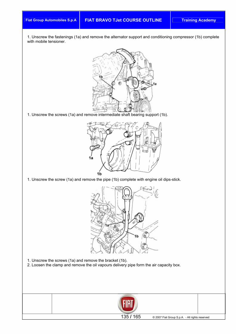
Fiat Group Automobiles S.p.A FIAT BRAVO TJet COURSE OUTLINE Training Academy
135 / 165 © 2007 Fiat Group S.p.A. - All rights reserved
1. Unscrew the fastenings (1a) and remove the alternator support and conditioning compressor (1b) complete with mobile tensioner.
1. Unscrew the screws (1a) and remove intermediate shaft bearing support (1b).
1. Unscrew the screw (1a) and remove the pipe (1b) complete with engine oil dips-stick.
1. Unscrew the screws (1a) and remove the bracket (1b). 2. Loosen the clamp and remove the oil vapours delivery pipe form the air capacity box.

Fiat Group Automobiles S.p.A FIAT BRAVO TJet COURSE OUTLINE Training Academy
© 2007 Fiat Group S.p.A. – All rights reserved 136 / 165
1. Unscrew the screws (1a) and remove the air capacity box (1b).
1. Unscrew the screws (1a) and remove the oil vapours separator (1b).
1. Unscrew the fastenings and remove the bracket (1a) complete with pressurised air by-pass solenoid (1b).

Fiat Group Automobiles S.p.A FIAT BRAVO TJet COURSE OUTLINE Training Academy
137 / 165 © 2007 Fiat Group S.p.A. - All rights reserved
1. Unscrew the screws and remove the engine oil filter heat guard. 2. Unscrew the screws and remove the heat guard for the engine water-oil exchanger.
1. Unscrew the fastenings and remove the turbocompressor heat guard.
1. Unscrew the screws securing the turbocompressor lubricating oil return pipe to the engine crankcase, on the turbocompressor side.
. Unscrew the screws securing the turbocompressor lubricating oil return pipe to the engine crankcase, on the
pipe to the engine rankcase, on the engine oil exchanger side, and remove it.
2engine crankcase side.
. Unscrew the intermediate union securing the turbocompressor lubricating oil return3c

Fiat Group Automobiles S.p.A FIAT BRAVO TJet COURSE OUTLINE Training Academy
© 2007 Fiat Group S.p.A. – All rights reserved 138 / 165
engi1. Unscrew the union of the water to ne oil heat exchanger delivery pipe, on the exchanger side. pipe, on the thermostat side. 2. Unscrew the union of the water to engine oil heat exchanger delivery
3. Unscrew the screw (3a) and remove the water to engine oil heat exchanger delivery pipe (3b).
1. Unscrew the union of the water return pipe from the engine oil heat exchanger, on the heat exchanger side. 2. Unscrew the union of the water return pipe from the engine oil heat exchanger, on the return pipe to the water pump side, and remove it.
1. Unscrew the union of the turbocompressor lubricating oil delivery pipe, on the heat exchanger side.
turbocompressor lubricating oil delivery pipe, on the turbocompressor side. 2. Unscrew the union of the

Fiat Group Automobiles S.p.A FIAT BRAVO TJet COURSE OUTLINE Training Academy
139 / 165 © 2007 Fiat Group S.p.A. - All rights reserved
3. Unscrew the screw securing the intermediate bracket of the turbocompressor lubricating pipe, and remove it.
1. Unscrew the union the union, on the turbocompressor
p side, and remove it. side.
2. Unscrew the union the union, on the return pipe to the water pum
1. Unscrew the nuts (1a) and remove the exhaust manifold heat shield (1b).
1. Unscrew the nuts (1a) and remove the exhaust manifold-turbocompressor assembly (1b).

Fiat Group Automobiles S.p.A FIAT BRAVO TJet COURSE OUTLINE Training Academy
1. Unscrew the screw securing the return pipe to the water pump, cylinder head side. 2. Unscrew the screw securing the return pipe to the water pump, crankcase side. 3. Remove the return pipe to the water pump complete with seal.
. Unscrew the screw securing the oil filter support assy and engine oil heat exchanger, on crankcase side. e union (2a) securing the oil filter support and engine oil heat exchanger (2b), on crankshaft oil
eal front cover side, and remove it.
12. Unscrew ths
. Unscrew the screws (1a) and remove crankshaft pulley (1b). belt covers (2b).
© 2007 Fiat Group S.p.A. – All rights reserved 140 / 165
12. Unscrew the screws (2a) and remove valve train

Fiat Group Automobiles S.p.A FIAT BRAVO TJet COURSE OUTLINE Training Academy
1. Unscrew the screws (1a) and remove the engine rigid support (1b).
1. Unscrew the screws and remove ignition coils.
141 / 165 © 2007 Fiat Group S.p.A. - All rights reserved
1. Fit the tool (1a) blocking the camshaft conduit pulley (1b).
2000015800 Locking tool Locking camshaft conduit pulley 1.4 16v

Fiat Group Automobiles S.p.A FIAT BRAVO TJet COURSE OUTLINE Training Academy
1. Unscrew nuts (1a) and remove the cover (1b).
1. Loosen the ).
screws (1a) securing camshaft rear gears (1b
1. Unscrew the screw (1a) and remove camshaft conduit pulley (1b).
© 2007 Fiat Group S.p.A. – All rights reserved 142 / 165

Fiat Group Automobiles S.p.A FIAT BRAVO TJet COURSE OUTLINE Training Academy
Unscrew the screw and remove the tool locking the camshaft conduit pulley. 1. Unscrew the caps protecting the screws securing the upper part of the cylinder head. 2. Using tool (2a) unscrew the screws (2b) securing upper part of cylinder head.
1860834000 Wrench Unscrew/tighten screws on upper part of cylinder head 1.4 16v
3. Position the tool for retaining the tappets (3a) under the upper part of the head (3b) and remove it.
1860988000 Tappet retainer tool Tappet retainer 1.4 16v
4. Remove the gasket.
1
143 / 165 © 2007 Fiat Group S.p.A. - All rights reserved
. Unscrew the screws (1a), remove the cylinder head (1b) and re2. Remove the dowels.
cover the gasket (1c).

Fiat Group Automobiles S.p.A FIAT BRAVO TJet COURSE OUTLINE Training Academy
- Turn the engine 180° on the overhaul stand. 1. Unscrew the screws (1a) and nuts (1b) securing the engine o rankcase2. Using the tool, cut the silicone sealant all along the perimeter of the engi sump
1870718000 Blade Cut sealant
il sump to the cne oil
.
3. Remove engine oil sump.
Note- Thoroughly clean the contact surfaces between the crankcase and oil sump.
© 2007 Fiat Group S.p.A. – All rights reserved 144 / 165

Fiat Group Automobiles S.p.A FIAT BRAVO TJet COURSE OUTLINE Training Academy
1004E20 ENGINE – SS. AFTER OP. 1004E10 G AND C OVED PARTS – C P FITTING – DOES ORKS O DER HEAD AND AUXILIARY COMPONENTS REMOVAL: 1. Remove the screws (1a) and the nut (1b) fastening the water pump to the crankcase. 2. Remove the sealant with the tool (2°) and remove the water pump (2b).
Cut sealant
DISM. AND REAYLINDER HEAD AND SUM
– CLEANIN NOT INCLUDE W
HECKING REMN CYLIN
1870718000 Blade
Thoroughly clean the crankcase-water pump coupling surfaces. 3. Remove th e oil minimum p ssure switch.
e engin re
1. Fit the tool (1a) and unscrew the screw (1b) fastening the crankshaft gear
2000004500 Template Crankshaft timing 1.4 16v
Remove the previously fitted template. 2. Remove the crankshaft gear. 3. Remove the screws (3a) and remove the revs sensor (3b).
145 / 165 © 2007 Fiat Group S.p.A. - All rights reserved

Fiat Group Automobiles S.p.A FIAT BRAVO TJet COURSE OUTLINE Training Academy
1. Unscrew th kcase cover (1 mp, compl(1c) and i
e screws (1a) and remove the front cranntake funnel (1d).
b) with oil pu ete with the gasket
1. Unscrew the screws (1a) and remove the rear crankshaft cove
r (1b) with oil seal.
Turn the crankcase by 180°. 1. Fit the tool for turning the crankshaft.
Crankshaft rotation 1.4 16v 1860815000 Flange
1. Unscrew the screws (1a) and remove the big end caps (1b).
© 2007 Fiat Group S.p.A. – All rights reserved 146 / 165
2. Remove the lower half-bearings.

Fiat Group Automobiles S.p.A FIAT BRAVO TJet COURSE OUTLINE Training Academy
3. Remove the con rod-piston assembly. 4. Remove the upper half-bearings. There is an arrow on f the piston thThe con rod-cap coupling is “BREAK” type and n is also punched with
the top o at indicates fitting position. so with mandatory positioning. The pisto
the corresponding cylinder number.
Remove the previously fitted flange for turning the crankshaft. Usin heck that crankshaft axial play is within the specified values. g a comparator, c
Crankshaft axial play (mm) 0.155 ÷ 0.355 1.4 16v
Remo ator.
kshaft axial play is not within the specified values, the crankcase journals must be machined and the entral crankshaft journal fitted with suitably oversize half bearings before refitting the crankshaft.
ve the comparIf cranc
. Unscrew the screws (1a) and remove the lower crankcase (1b) complete with half-bearings. 1
147 / 165 © 2007 Fiat Group S.p.A. - All rights reserved

Fiat Group Automobiles S.p.A FIAT BRAVO TJet COURSE OUTLINE Training Academy
1. Remove the lower half-bearings from the crankcase. . Remove the crankshaft. 2
3. Remove the upper half-bearings.
1. Unscrew the screws and remove the pinging sensor.
Remove the lower crankcase-engine block centering bushes. Suitable ha kcase and lift it onto oist. O
ND RINGS SET – REPL. PISTON WITH CON-RODS ON BENCH – INCLUDES
rness the cranp. 1028H60
a suitable workbench using a hydraulic h
PISTON, PINS AB
© 2007 Fiat Group S.p.A. – All rights reserved 148 / 165
ALANCING Op. 1084B18

Fiat Group Automobiles S.p.A FIAT BRAVO TJet COURSE OUTLINE Training Academy
ENGINE OIL PUMP, REMOVED – BENCH CHECK 1. Remove the plugs from the crankcase cooling fluid chambers with a suitable steel driver. . Remove lubrication channel plug from the crankcase with a suitable steel driver.
2
1. Remove the oil sprayers (1a) using the tool (1b).
1860395000 Dri Engine oil spver rayers removal 1.4 16v
Insert the guide hole of the driver over the sprayer surface to prevent the driver from slipping and damaging the cylinder barrel. Use new oil sprayers when reassembling.
REASSEMBLY: - Clean and visually inspect the condition of all removed components.
nkcase. . Using tool (1a) and a plastic mallet, fit the new oil sprayers (1b).
1
- Position the crankcase on the overhaul stand. - Fit the water/oil plugs to the crankcase using suitable inserters and sealant. - Fit the centering bushes to the cra1
1860313000 Inserter Engine oil sprayer insertion .4 16v
149 / 165 © 2007 Fiat Group S.p.A. - All rights reserved

Fiat Group Automobiles S.p.A FIAT BRAVO TJet COURSE OUTLINE Training Academy
1. Using a calibrated metal rule 1a) and a feeler gauge (1b), check the flatness of the cylinder head-crankcase coupling surfaces. 2. If flatness is not within the specified values, machine the cy r head.
Cylinder head contact surface flatness (mm) < 0.1 1.4 16v
linde
Measure and check that the diameter of the cylinder barrels is within specified va
lues.
72.000 ÷ 7Barrel diameter - Class A (mm) 2.010 1.4 16v
Barrel diameter - Class B (mm) 72.010 ÷ 72.020 1.4 16v
Barrel diameter - Class C (mm) 72.020 ÷ 72.030 1.4 16v
Check that barrel ovalization is within specified values.
Barrel ovalization (mm) +/- 0.05 1.4 16v
Check that barrel taper is within specified values.
Barrel taper (mm) +/- 0.005 1.4 16v
© 2007 Fiat Group S.p.A. – All rights reserved 150 / 165

Fiat Group Automobiles S.p.A FIAT BRAVO TJet COURSE OUTLINE Training Academy
If barrel diameter, ovalization or taper is not within specifications, ream the barrels to the required oversizeIf reamin
. g is necessary, all barrels must be brought to the same oversize.
1
Barrel oversize (mm) 0.1 .4 16v
Check that main journal diameters are within specified values.
Main journal diameter - Class A (mm) 47.994 ÷ 48.000 1.4 16v
Main journal diameter - Class B (mm) 47.988 ÷ 47.994 1.4 16v
Main journal diameter - Class C (mm) 47.982 ÷ 47.988 1.4 16v
main journal diameters are not within specifieIf d values, machine them to the required undersize.
The crankshaft is nitrided. If machined, it must undergo liquid nitride treatment again, followed by a dimensional check.
Main journal undersize (mm) 0.127 1.4 16v
Check that the diameters of the crank pins are within specified values.
Crank pin diameter (mm) 41.990 ÷ 42.008 1.4 16v
If the crank pins are not within the specified values, machine them down to the required undersize. The crankshaft is nitrided. If machined, it must undergo liquid nitride treatment again, followed by a
Crank pin undersize (mm) 0.127 1.4 16v
dimensional check
Check the crankshaft main bearings. These cannot be machined. If scoring or signs of seizure are found, they must be replaced. Fit the crankshaft half-shells to the seats in the upper crankcase and align the oil holes. This operation must be carried out in scrupulously clean conditions. The central half-bearings have built-in shoulder half-rings, since it
the crankshaft has been machined, fit new suitably oversized half-bearings, to restore the original tolerance. 1. Fit the crankshaft into its seat on the crankcase fitted with the corresponding upper half-bearings.
also serves as thrust bearing. IF
151 / 165 © 2007 Fiat Group S.p.A. - All rights reserved
2. Apply the plastigage to measure main journal play.

Fiat Group Automobiles S.p.A FIAT BRAVO TJet COURSE OUTLINE Training Academy
1. Fit the lower half-bearings onto the lower crankshaft. 2. Fit the lower crankcase to the upper engine block checking that the punch markings on both crankcase omponents correspond, since the crankcase components are not interchangeable. c
The following table gives the main journal half-bearing thickness.
v
Main journal half-bearing thickness - Class 1 (Red) (mm) 1.836 ÷ 1.840 1.4 16
Main journal half-bearing thickness - Class 2 (Blue) (mm) 1.843 ÷ 1.847 1.4 16v
Main journal half-bearing thickness - Class 3 (Yellow) (mm) 1.848 ÷ 1.852 1.4 16v
Main journal half-bearing undersize (mm) 0.127 1.4 16v
Tighten the lower and upper crankcase bolts to the specified torque.
Crankcase Centre bolt M10 1.9 ÷ 2.1 + 87° ÷ 93° 1.4 16v
© 2007 Fiat Group S.p.A. – All rights reserved 152 / 165
Crankcase Side bolt M10 2.8 ÷ 3.2 1.4 16v

Fiat Group Automobiles S.p.A FIAT BRAVO TJet COURSE OUTLINE Training Academy
1. Remove the lower crankcase and check main journal play by measuring the width of the plastigage with a specific measuring tool. Ch at a urning the
bearin kshaft journals play (mm) 0.025 ÷ 0.040 1.4 16v
eck one journal time without t crankshaft.
Main gs – cran
After ch all jo nt between t upper crankcases and complete the final cou r cran se, tightening the ified torque. A ous b e. Thickness 2 mm. Check that the external diameter of the pistons is within specified values. If not, replace the pistons along with r
exte eter - Class A (m 1.4 16v
ecking urnals, apply seala he lower andpling of the lowe
pply a continukca
ead of sealant to the lowebolts to the previously specr crankcase coupling surfac
ings and pins.
Piston rnal diam m) 71.960 ÷ 71.970
Piston exte ter - Class B (m 1.4 16v rnal diame m) 71.970 ÷ 71.980
Piston exte - Class C (m 0 1.4 16v rnal diameter m) 71.980 ÷ 71.99
Measure perpendicula eon pin axis at 9 mm ge of skirt. Fit the piston sure play with uge.
iston r barrel play (mm 0.050 1.4 16v
r to gudg from lower eds into the barrels and mea a feeler ga
P - cylinde ) 0.030 ÷
Che
153 / 165 © 2007 Fiat Group S.p.A. - All rights reserved
ck that internal diameter of the gudgeon pin seat is within specified values. If not, replace the pistons.
Gudgeon pin seat (mm) 17.978 ÷ 17.982 1.4 16v
Check that the external diameter of the gudgeon pins is within specified values. If not, replace the worn parts.
Gudgeon pin external diameter (mm) 17.970 ÷ 17.974 1.4 16v
Using a micrometer, measure the thickness of the piston rings.

Fiat Group Automobiles S.p.A FIAT BRAVO TJet COURSE OUTLINE Training Academy
© 2007 Fiat Group S.p.A. – All rights reserved 154 / 165
1 P
stP compression ring thickness (mm) 1,170 ÷1,195 1.4 16v
2 P
ndP compression ring thickness (mm) 1.170 ÷ 1.190 1.4 16v
3 P
rdP compression ring thickness (mm) 1.970 ÷ 1.990 1.4 16v
Piston ring oversize (mm) 0.1 1.4 16v
1. Fit the piston rings (1a) to the piston and using a micrometer (1b) check that the distance between the ends of the rings is within specified values. If not, replace the rings.
1 P
stP compression ring distance (mm) 0.20 ÷ 0.35 1.4 16v
2 P
ndP compression ring distance (mm) 0.40 ÷ 0.60 1.4 16v
3 P
rdP compression ring distance (mm) 0.20 ÷ 0.40 1.4 16v
Check that the ring seats on the pistons are within specified values.
Piston ring seat – 1 P
stP groove (mm) 1.220 ÷ 1.240 1.4 16v
Piston ring seat – 2 P
ndP groove (mm) 1.210 ÷ 1.230 1.4 16v
Piston ring seat – 3 P
rdP groove (mm) 2.010 ÷ 2.030 1.4 16v
1. Using a feeler gauge (1a) check play between the rings (1b) and the grooves on the pistons (1c).
1 P
stP compression ring axial play (mm) 0.025 ÷ 0.070 1.4 16v
2 P
ndP compression ring axial play (mm) 0.020 ÷ 0.060 1.4 16v

Fiat Group Automobiles S.p.A FIAT BRAVO TJet COURSE OUTLINE Training Academy
155 / 165 © 2007 Fiat Group S.p.A. - All rights reserved
3 P
rdP compression ring axial play (mm) 0.020 ÷ 0.060 1.4 16v
Check that the diameters of the con rod big ends and small ends are within specified values.
Big end diameter (mm) 45.138 ÷ 45.148 1.4 16v
Small end diameter (mm) 17.993 ÷ 18.000 1.4 16v
Op.1028H60 PISTON, PINS AND RINGS SET – REPL. PISTON WITH CON-RODS ON BENCH – INCLUDES BALANCING Op.1084B18 OIL PUMP, REMOVAL – BENCH CHECK Fit the tool for turning the crankshaft.
1860815000 Flange Crankshaft turning 1.4 16v
The con rod-piston assemblies must be fitted and aligned with the following references. 1. Piston class and arrow pointing to valve train side 2. Barrel number to which the con rod assembly corresponds 3. Gudgeon pin offset
The con rod-cap coupling is “BREAK” type and so with mandatory positioning. The piston is also punched with the corresponding cylinder number.

Fiat Group Automobiles S.p.A FIAT BRAVO TJet COURSE OUTLINE Training Academy
© 2007 Fiat Group S.p.A. – All rights reserved 156 / 165
The barrel class letter is marked on the crankcase. 1. Fit the con rod-piston assembly (1a) complete with half-shells using the tool (1b) for compressing the piston rings and inserting the piston into the barrel.
Turn the engine on the overhaul stand. 1. Apply Plastigage to measure crank pin play.
The following table gives the thickness of the big end half-bearings.
Standard big end bearings (mm) 1.544 ÷ 1.548 1.4 16v
Oversize big end bearings 0.127 mm 1.607 ÷ 1.611 1.4 16v
Oversize big end bearings 0.254 mm 1.669 ÷ 1.675 1.4 16v
Oversize big end bearings 0.508 mm 1.796 ÷ 1.802 1.4 16v
Fit the con rod caps complete with half-shells and fasten with the bolts to the specified torque. The con rods have fracture type big end caps. If replaced they are supplied pre-fractured. Check that parts are free of burrs, bubbles, scratches or other surface faults. Before fitting the parts must be thoroughly cleaned and dried. The con rod caps must be fitted with the punch marking facing the same way as the one on the big end. Each con rod must be coupled with its corresponding cap, according to the numbers punched on it. Con rods and con rod caps are not interchangeable.

Fiat Group Automobiles S.p.A FIAT BRAVO TJet COURSE OUTLINE Training Academy
157 / 165 © 2007 Fiat Group S.p.A. - All rights reserved
Con rod caps Screw M8 1.9 ÷ 2.1 + 40° +/- 2° 1.4 16v
1. Remove the con rod caps and check crank pin play measuring the width of the plastigage with a specific measuring tool. Check one crank pin at a time without turning the crankshaft.
Big end bearings – crankshaft crank pin play (mm) 0.024 ÷ 0.060 1.4 16v
If the measured values are not within specifications, replace the big end bearings.
Refit the con rod caps with half-shells and fasten the bolts to the previously specified torque. Turn the engine on the overhaul stand. Fit a new oil pump gasket. Replace the crankcase front cover with oil pump in its seat, complete with intake funnel, and fasten the bolts to the specified torque
Engine oil pump Screw M6 0.9 ÷ 1.1 1.4 16v
Replace the minimum oil pressure switch in its seat and fasten it to the specified torque.
Engine oil minimum pressure switch M14 2.9 ÷ 3.5
Fit the oil seal to the crankshaft front cover using the tool.
1860990000 Inserter Crankshaft front cover oil seal insertion Exhaust side camshaft oil seal fitting 1.4 16v
Remove the previously fitted flange used to turn the crankshaft. Fit a new crankcase rear cover and fasten the bolts to the specified torque.
Crankshaft rear cover on crankcase Screw M6 0.8 ÷ 1.0 1.4 16v
Refit the cog onto the crankshaft.

Fiat Group Automobiles S.p.A FIAT BRAVO TJet COURSE OUTLINE Training Academy
© 2007 Fiat Group S.p.A. – All rights reserved 158 / 165
1. Valve train timing must be carried out with the four pistons aligned, meaning at halfway through the stroke. It is essential to align the crankshaft with the camshafts. Approximate positioning can be obtained by turning the crankshaft gear (1a) until the centering pin (1b) is opposite to the revs sensor (1c) and with the first piston descending on the intake stroke.
1. Position of locking tool.
2000004500 Template Crankshaft timing 1.4 16v
2. Fasten the crankshaft gear (2a) with the screw (2b), tightening it to the specified torque.
Crankshaft gear Screw M12 1.9 ÷ 2.1 + 107° ÷ 113° 1.4 16v
3. Fit the revs sensor to its seat (3a) and fasten it with the corresponding bolt (3b) to the specified torque.
Revs sensor Screw M6 0.8 ÷ 1.0 1.4 16v
Apply silicon sealant to the groove on the flange fastening the water pump to the crankcase Position the water pump in its seat and secure it with the corresponding bolts and nut to the specified torque.

Fiat Group Automobiles S.p.A FIAT BRAVO TJet COURSE OUTLINE Training Academy
159 / 165 © 2007 Fiat Group S.p.A. - All rights reserved
Water pump Screw M6 0.9 ÷ 1.1 1.4 16v
Water pump Nut M6 0.9 ÷ 1.1 1.4 16v
Turn the engine 180° on the overhaul bench. Clean the surfaces between the lower crankcase and oil sump, removing any silicon sealant residues. Apply a continuous bead of sealant to the entire perimeter of the oil sump. Refit the sump and fasten it with the nuts and bolts, to the specified torque. When positioning the oil sump, avoid any significant horizontal shift that could remove the sealant.
Engine oil sump Screw M6 0.8 ÷ 1.0 1.4 16v
Engine oil sump Nut M6 0.8 ÷ 1.0 1.4 16v
Turn the engine by 180° on the overhaul stand. Fit the centering bushes to the crankcase. Fit a new cylinder head gasket to the crankcase. Position the cylinder head on the block, aligning the centering bushes. 1. Tighten the cylinder head bolts to the specified torque. For each tightening sequence, follow the order given in the diagram.
Cylinder head Screw M9 3 + 90° + 90° 1.4 16v
Fit the centering bushes and position the upper cylinder head gasket on the lower cylinder head. Fit the tools for retaining the tappets below the upper head, then position the upper head on the cylinder head and remove the retainers. Using the tool, tighten the upper head bolts to the specified torque.
1860834000 Wrench Loosen/tighten upper head bolts 1.4 16v
Upper cylinder head Screw M8 1.3 ÷ 1.6 1.4 16v

Fiat Group Automobiles S.p.A FIAT BRAVO TJet COURSE OUTLINE Training Academy
© 2007 Fiat Group S.p.A. – All rights reserved 160 / 165
Refit the plugs with new o-rings and tighten them to the specified torque.
Upper cylinder head plugs M16 1.3 ÷ 1.6 1.4 16v
Refit the camshaft drive pulley without tightening the bolts. Fit the camshaft drive pulley locking tool.
2000015800 Locking tool Timing adjuster/camshaft drive pulley 1.4 16v
Tighten the camshaft drive pulley bolts to the specified torque. Camshaft drive pulley Bolt, M12; 10.8 - 13.2 daNm, Val. 1.4 16v TJet Tighten the camshaft drive gears bolts to the specified torque.
Camshaft gears Screw M12 12.0 1.4 16v
Loosen the camshaft drive pulley bolts and remove the locking tool. Remove the previous tool used as lock for tightening the camshaft drive gear bolts. 1. Fit the tools (1a) into the seats of the 1 P
stP and 2P
ndP cylinder spark plugs, tightening the pins (1b) to a torque of
0.5 daNm.
1860992000 Pins Crankshaft timing 1.4 16v
2. Turn the crankshaft in its normal direction until the mobile pins of the previously mounted tool are all aligned. Turn the crankshaft gradually to prevent the tools from being pushed out by piston compression. 3. The camshafts have been previously timed by applying the tools shown in the diagram.
1860985000 Centering pins Camshaft timing 1.4 16v

Fiat Group Automobiles S.p.A FIAT BRAVO TJet COURSE OUTLINE Training Academy
161 / 165 © 2007 Fiat Group S.p.A. - All rights reserved
Proceed to fit the valve train drive belt, initially fitting it to the crankshaft gear, then the water pump pulley, the camshaft drive pulley and lastly onto the tensioner. Check that this operation is carried out with the camshaft pulley loosened. 1. Tighten the valve train belt by turning the tensioner (1b) anticlockwise with the tool (1a), and fasten it when the reference fork (1c) is flush (1d)
1860987000 Wrench Valve train drive belt tightening 1.4 16v
Fit the camshaft pulley locking tool.
2000015800 Locking tool Timing adjuster/drive pulley locking 1.4 16v
Tighten the camshaft drive pulley screw to the specified torque.

Fiat Group Automobiles S.p.A FIAT BRAVO TJet COURSE OUTLINE Training Academy
© 2007 Fiat Group S.p.A. – All rights reserved 162 / 165
Valve train drive pulley, Screw, M12; 10.8 - 13.2 daNm, Val. 1.4 16v TJet Remove the previously fitted tools for timing and locking the camshafts, and turn the crankshaft by two turns. 1. Loosen the tensioner fastening nut and work on the front fork with the tool (1a) until it coincides with the rear fork (1b). 2. Tighten the tensioner nut to the specified torque.
Valve train drive belt tensioner Nut M8 2.2 ÷ 2.7 1.4 16v
Turn the crankshaft another two turns in its normal direction, then reposition the tools used for engine timing and check that the engine is correctly timed. Remove the engine timing tools. Replace the upper head side plugs and tighten them to the specified torque.
Upper cylinder head plugs M16 1.3 ÷ 1.6 1.4 16v
Replace the flywheel side rear camshaft cover and fasten it with the corresponding nuts. Replace the rigid water pump intake pipe, complete with new gasket, and fasten it with the bolts to the crankcase and cylinder head, tightening to the specified torque.
Rigid water pump intake pipe Screw M6 0.9 ÷ 1.1 1.4 16v
Replace the ignition coils in their respective seats and fasten them to the specified torque.
Ignition coils Screw M6 0.8 ÷ 1.0 1.4 16v
Replace the timing sensor in its seat and fasten it with the corresponding screw. Replace the rigid engine support, valve train side, in its seat and fasten it with the screws to the specified torque.
Rigid engine support, valve train side Screw M8 2.2 ÷ 2.7 1.4 16v
Replace the upper and lower valve train drive belt covers and fasten them with the corresponding screws. Replace the crankshaft pulley and fasten is with the corresponding screws to the specified torque.

Fiat Group Automobiles S.p.A FIAT BRAVO TJet COURSE OUTLINE Training Academy
163 / 165 © 2007 Fiat Group S.p.A. - All rights reserved
Auxiliary pulley on crankshaft Screw M8 2.3 ÷ 2.8 1.4 16v
Replace the oil filter and engine oil heat exchanger in its seat and fasten the connector, crankshaft oil seal cover side, to the specified torque. Engine oil filter and heat exchanger support – crankshaft oil seal cover side – Connector - M20 - 4.1 - 4.9 daNm, Val. 1.4 16v TJet Tighten the oil filter and heat exchanger assembly screws, crankcase side, to the specified torque. Oil filter and heat exchanger support – crankcase side - Screw- M10 - 4.5 - 5.5 daNm, Val. 1.4 16v TJet Replace the exhaust manifold – turbo compressor assembly in its seat, complete with a new gasket, and tighten the new nuts to the specified torque. Exhaust manifold – Nut (to be replaced) - M8, 1.4 - 1.6 + 30° +/- 2° daNm - Val. 1.4 16v Tjet Replace the exhaust manifold heat shield in its seat and tighten the corresponding nuts to the specified torque. Exhaust manifold heat shield, Nut, M6, 0.8 - 1.0 daNm, Val. 1.4 16v TJet Replace the turbo compressor coolant return pipe in its seat, complete with new gasket, and tighten the corresponding connectors. Replace the turbo compressor oil delivery pipe in its seat, complete with new gasket and tighten the connectors to the specified torque. Turbo compressor oil delivery pipe – heat exchanger side, Connector, M6, 0.8 - 1.0 daNm, Val. 1.4 16v TJet Turbo compressor oil delivery pipe – turbo compressor side, Connector, M12, 1.8 - 2.2 daNm, Val. 1.4 16v TJet Tighten the turbo compressor oil delivery pipe intermediate bracket screws. Replace the water return pipe from the engine oil heat exchanger, complete with new gasket, and tighten it the corresponding connectors. Replace the water delivery pipe to the engine oil heat exchanger, complete with new gasket, and tighten the corresponding connectors to the specified torque. Water delivery pipe to engine oil heat exchanger, Connector, M16, 3.0 - 3.6 daNm, Val. 1.4 16v TJet Tighten the screw of the water delivery pipe to the engine oil heat exchanger. Replace the turbo compressor oil return pipe, complete with new gaskets, and tighten the corresponding screws to the specified torque. Turbo compressor oil return pipe to crankcase, Screw, M6, 0.8 - 1.0 daNm, Val. 1.4 16v TJet Tighten the intermediate connector fastening the turbo compressor oil return pipe to the crankcase, engine oil heat exchanger side. Turbo compressor lubricating oil return pipe to sump, Connector, M16, 3.0 - 3.6 daNm, Val. 1.4 16v TJet Replace the heat shield for the water-oil heat exchanger in its seat and tighten the corresponding screws to the specified torque. Heat shield for engine oil-water heat exchanger, Screw, M6, 0.8 - 1.0 daNm, Val. 1.4 16v TJet Replace the engine oil filter heat shield in its seat and tighten the corresponding screws to the specified torque. Engine oil filter heat shield, Screw, M6, 0.8 - 1.0 daNm, Val. 1.4 16v TJet Replace the bracket complete with pressurized air by-pass solenoid valve in its seat and tighten the corresponding fasteners. Replace the oil vapor separator in its seat and tighten the corresponding screws. Replace the air capacity box in its seat and tighten the new screws to the specified torque. Air capacity box, Screw (to be replaced), M6, 0.8 - 1.0, Val. 1.4 16v TJet

Fiat Group Automobiles S.p.A FIAT BRAVO TJet COURSE OUTLINE Training Academy
© 2007 Fiat Group S.p.A. – All rights reserved 164 / 165
Connect the oil vapour delivery pipe to the air capacity box and tighten the corresponding clamp. Replace the air capacity box support bracket and tighten the corresponding screws. Replace the engine oil dipstick tube in its seat and fasten it with the corresponding screw. Replace the intermediate shaft bearing support in its seat and fasten the screw to the specified torque. Intermediate shaft bearing support, Screw, M8, 2.3 - 2.8 daNm, Val. 1.4 16v TJet Replace the alternator and air-conditioner compressor support in its seat and tighten the corresponding screws to the specified torque.
Alternator/air-conditioner compressor support Screw M10 4.5 ÷ 5.5 1.4 16v
Replace the alternator in its seat and tighten the corresponding screws. Replace the air-conditioner compressor in its seat and tighten the corresponding screws. Fit the engine auxiliaries belt using the tensioner and remove the locking pin. Replace the engine wiring harness in its seat and tighten the ignition coils cable duct fastening screw. Connect the ignition coil electrical connections. Connect the timing sensor. Connect the ground cable and tighten the corresponding screw. Connect the engine coolant temperature sensor. Connect the pressurized air by-pass control solenoid valve. Connect the throttle body. With the retainer clips, connect the air capacity box wiring conduit. Connect the fuel vapor solenoid valve. Connect the pinging sensor. Connect the electro injectors wiring connection. Connect the air-conditioner compressor. Connect the alternator ground wire and tighten the corresponding nut. Replace the valve train drive belt inner cover in its seat and tighten it with the corresponding screws. Connect the ground cable to the auxiliaries support and tighten the corresponding screw. Connect the air temperature and pressure sensor. Connect the exhaust gas temperature sensor. Connect the engine oil minimum pressure switch. Connect the engine revs sensor.
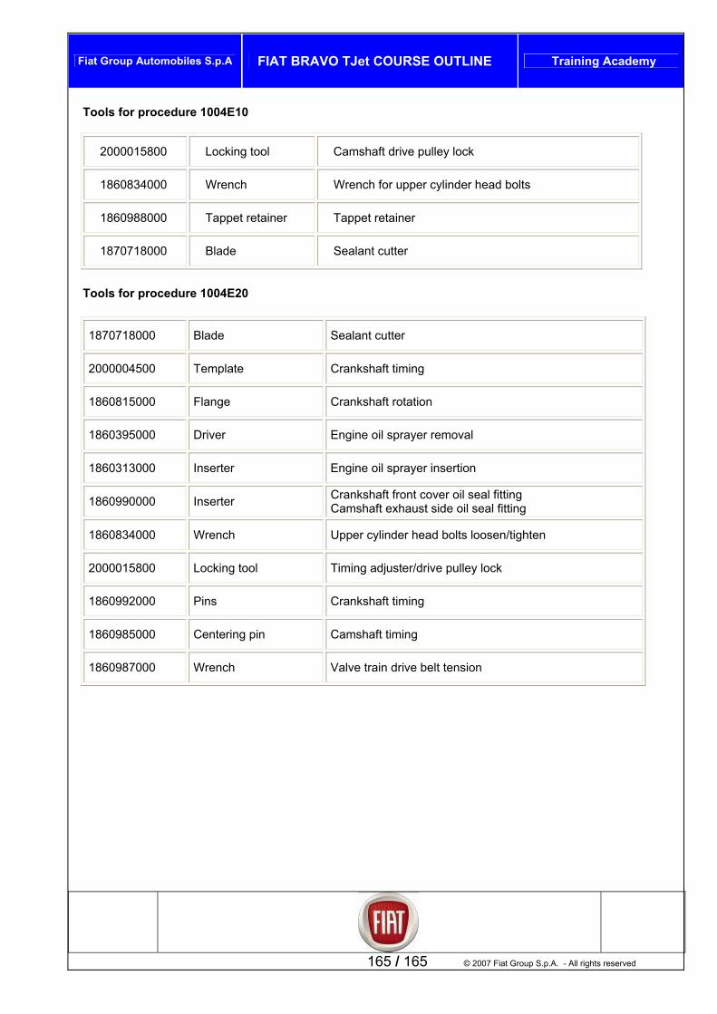
Fiat Group Automobiles S.p.A FIAT BRAVO TJet COURSE OUTLINE Training Academy
165 / 165 © 2007 Fiat Group S.p.A. - All rights reserved
Tools for procedure 1004E10
2000015800 Locking tool Camshaft drive pulley lock
1860834000 Wrench Wrench for upper cylinder head bolts
1860988000 Tappet retainer Tappet retainer
1870718000 Blade Sealant cutter
Tools for procedure 1004E20
1870718000 Blade Sealant cutter
2000004500 Template Crankshaft timing
1860815000 Flange Crankshaft rotation
1860395000 Driver Engine oil sprayer removal
1860313000 Inserter Engine oil sprayer insertion
1860990000 Inserter Crankshaft front cover oil seal fitting Camshaft exhaust side oil seal fitting
1860834000 Wrench Upper cylinder head bolts loosen/tighten
2000015800 Locking tool Timing adjuster/drive pulley lock
1860992000 Pins Crankshaft timing
1860985000 Centering pin Camshaft timing
1860987000 Wrench Valve train drive belt tension