Embed Size (px)
DESCRIPTION
manual
Citation preview

Fiat Bravo/a Service Manual Volume 1
C l i c k here to c h o o s e chapte r
Gearbox Jk Oiff
^ Broking System 1
•y Braking System 2
file:///D|/Volume%201/Voll .htm08/07/2006 16:03:54

Bravo-Brava I n t r o d u c t i o n a n d t e c h n i c a l d a t a * Index
N.D. Data not available at the time of . ' printing
The missing, data for the Diesel and 1581 versions with automatic transmission awe contained in the 3rd Volume.
INTRODUCTION
- Car exterior -Identification-data - Weights - Performance-Fuel consumption - Dimensions . -- Capacities -Characteristics of Fiat Lubricant
products TECHNICAL DATA
0 0 . page
1 2 4 5 6
. 8
E N G I N E 12V\ 16V 16V 20V
Characteristics v , 10 Typical curves _ ^ , 1 1
rCylinderiblock/crankcase, crankshaft and associated components - AuxHiary^shaft
^ -Cylinder head assembly and valve components , v -~: Counter-balance shaft
Lubrication ' ^ - Cooling system - Fuel system
- F u e l system
- 12 17
gear IS 23 24
-27 28
E N G I N E @ D i p TD
- Characteristics" 32 - Typical curves 33 - Cylinder block/crankcase, crankshaft and associated components 34 - Lubrication 42 - Cylinder head assembly and valve gear components 38 - Cooling system - Fuel systems . 43 - Fuel system . 44 -Supercharging 46
C L U T C H 47
G E A R B O X A N D D I F F E R E N T I A L 48
B R A K I N G S Y S T E M 52
S T E E R I N G 54
W H E E L S 55
F R O N T S U S P E N S I O N 57
R E A R S U S P E N S I O N 59
E L E C T R I C A L E Q U I P M E N T 60
- Starting 62 - Recharging -63 - Electronic injection/ignition 64
S P E C I A L T O O L S 68
T I G H T E N I N G T O R Q U E S V 79 P L A N N E D M A I N T E N A N C E 98
Copyright by FuLAtito Vf-96 - Cancels and replaces- •..

Bravo-Btava I n t r o d u c t i o n Car exterior
O O . o
P4A001A01
3/4 front view - Bravo
P4A001A02
3/4 front view - Brava
Copyright by Fiat Auto 1

I n t r o d u c t i o n Identification data
Bravo-Brava
O O . o
CHASSIS ENGINE VERSION 3 Door
5 Door
GEARBOX
l E S l i i2v
ZFA 182 000
182 A3.000 182 AA 1AA 00 •
• l E S l i i2v
ZFA 182 000
182 A3.000 182 BA 1AA 10 • • l E S l i i2v
ZFA 182 000
182 A5.000 ( • )
182 AG 1 AA 07 (•) • • l E S l i i2v
ZFA 182 000
182 A5.000 ( • ) 182 BG 1AA 16 (•) •
•
| ^ p | 16V
ZFA 182 000
182 A4.000
182 AB 1 AA 01 •
• | ^ p | 16V
ZFA 182 000
182 A4.000 182 AB 1 AA 01 B ( A ) •
• | ^ p | 16V
ZFA 182 000
182 A4.000 182 BB 1AA 11 •
• | ^ p | 16V
ZFA 182 000
182 A4.000
182 BB 1 AA 11 B ( A ) • •
ZFA 182 000
182 A6.000 ( • )
182 AH 1 AA 08 (•) •
•
ZFA 182 000
182 A6.000 ( • ) 182 BH 1 AA 17 (•) •
•
ZFA 182 000 182 A2.000
182 AC 1AA 03 •
•
ZFA 182 000 182 A2.000
182 AC 1AA 03B ( A ) •
•
ZFA 182 000 182 A2.000
182 BC 1AA 13 • •
ZFA 182 000 182 A2.000
182 BC 1AA 13B ( a ) • •
ZFA 182 000 182 A2.000
182 AC 1 BA 04 (*) •
•
ZFA 182 000 182 A2.000
182 BC 1 BA 14 (*) •
•
ZFA 182 000
182 A1.000 182 AD 1 AA 05 •
• K l 9 2 9 n ^ ^ H
ZFA 182 000
182 A1.000 182 AD 1 AA 05B ( A ) •
•
ZFA 182 000
160 A7.000 182 AE 1 AA •
•
ZFA 182 000
160 A7.000 182 BE 1 AA •
•
ZFA 182 000
N.D. N.D. • • •
( • ) Versions for specific markets (Germany) ( a ) Voluntary - Germany (*) Versions for specific markets (France)

Bravo-Brava I n t r o d u c t i o n Identification data
I 0 t mi6v
! B | D
1.
2. 3.
Vehicle type identification code and chassis manufacture number Engine type and number. V.I.N. Plate (EEC regulations)
o
B C D
E Kg F K9
1- G Kg
MOTORE-ENGINE 2- H Kg
I
O
VERSIONE-VERSION I N2 PER RICAMBI-N-FOR SPARES M N
O O . o S20V
A. B. C. D. E.
F.
G.
H.
I. L. M. N.
Name of manufacturer Homologation number Vehicle type identification code Chassis manufacture number Maximum authorized weight of vehicle fully laden Maximum authorized weight of vehicle fully laden plus tow Maximum authorized weight on first axle (front) Maximum authorized weight on second axle (rear) Engine type Bodywork version code Spares number Correct value of smoke absorption coefficient (Diesel engines only)
Copyright by Fiat Auto 111-96 - Cancels and replaces 3

I n t r o d u c t i o n Bravo-Brava Weights O O . o
WEIGHTS (in kg)
ENGINE T Y P E 12V 16V 16V 20V D TO
3 door 1010 1050 1100 1190 1100 N.D.
^ ^ ^ ^ ^ ^ ^ ^ 1040 1090 1130 - 1130 N.D.
_ 3 door
^ 3 5 door
1510 1550 1600 1690 1600 N.D. _ 3 door
^ 3 5 door 1570 1630 1680 - 1650 N.D.
3 door
, . 5 door IvmYimi im noirni^^inlp lmn r'
850 850 900 970 850 N.D. 3 door
, . 5 door IvmYimi im noirni^^inlp lmn r'
850 850 900 - 850 N.D.
1VIUAI1 1 1 LI 1 1 1 fJC?l 1 1 1 lOOl UIC? IVJCIUO on the axles • 3 d o o r
5 door
850 850 900 900 850 N.D. 1VIUAI1 1 1 LI 1 1 1 fJC?l 1 1 1 lOOl UIC? IVJCIUO on the axles • 3 d o o r
5 door 850 850 900 - 850 N.D.
Maximum permissible load on the roof 80 80 80 80 80 N.D.
Load on the tow hook Minimum - - - - - N.D.
^trailer wun uraKing sysiemj Maximum 70 70 70 70 70 N.D.
. Without braking II V V system 400 400 400 400 400 N.D.
O ^ - ^ - ^ ^ ^ ' With braking system
1000 1100 1200 1300 1200 N.D.
• Loads wh ich must never be exceeded
NOTE FOR VERSIONS WITH ACCESSORIES: If special equ ipment is f i t ted (non standard air condit ioner, sun roof, trailer tow ing device) , the empty we igh t increases and therefore the carrying capacity may decrease, in relation to the maximum permissible loads.
The fuel consumpt ion f igures according to the 8 0 / 1 2 6 8 / E E C standards given overleaf have been def ined in the course of official tests and in accordance w i t h procedures laid d o w n by EEC regulations. In particular the bench tests measure simulated urban cycle f igures whi ls t consumpt ion at constant speeds of 90 and 120 kph are measured directly on a f lat , dry road and in equivalent bench tests. The fuel consumpt ion f igures according to the 93 /116E standards have been defined in the course of homologat ion tests involv ing:
- an urban cycle w h i c h includes co ld starting fo l l owed by a varied urban cycle s imulat ion. - an extra-urban cycle wh ich includes frequent acceleration in all gears s imulat ing normal extra-urban usage of the
vehicle. The speed varies between 0 and 120 kph. - The average combined consumpt ion is obtained f rom 37% of the urban cycle and 63% of the extra-urban cycle.
The type of journey, traffic condi t ions, driving styles, atmospheric condi t ions, tr im level /equipment/accessor ies, whether a roof rack is f i t ted, the presence of special equipment and the general state of the vehicle can lead to fuel c o n sumpt ion figures wh i ch differ f rom those obtained through the above ment ioned procedures. The CO2 exhaust emissions (in g / k m ) are obtaine f rom the average combined cycle
4 VII 97 - Cnnools and replaces Print no. 506.670/12

Bravo-Brava I n t r o d u c t i o n Performance - Fuel consumption
O O . o
( • ) For French versions
| ^ | ENGINE TYPE | ^ | mc929m | ^ | 12V 16V lev 20V D TD
Speed kph (average load)
45 (46 A ) 52 50
(55») 56 35 N.D.
Speed kph (average load)
82 (80 A ) 90 87
(95«) 89 61 N.D. Speed kph (average load)
120 (118A) 132 128
(140») 131 94 N.D.
Speed kph (average load)
158 (155A) 175 169
(191 • ) 172 132 N.D.
Speed kph (average load)
170 ( 168B)
184 ( 1 8 0 B )
193 (190»)
210 155 N.D.
Speed kph (average load)
170 ( 168B) 180
(177 . ) 190
(190«)
210 155 N.D.
Speed kph (average load)
46 53 50 ( 5 5 . ) 55 35 N.D.
~ ~ ^ ^ ^ ^ P B | ^ ^ Maximum climat % ^ - - — g r a d i e n t
37 l^36A) 37 ~ ~ ^ ^ ^ ^ P B | ^ ^ Maximum climat
% ^ - - — g r a d i e n t (35A)
37
Fuel consumption according to 80 /1268/CEE stand. (litres/100 km) (*)
Urban cycle (A) 9 9,3 9,8
(9,5») 11 6,5 N.D. Fuel consumption according to 80 /1268/CEE stand. (litres/100 km) (*) Constant speed
90 kph (B) 5,2 5,5 5,8
(5,6#) 7,1 4,9 N.D.
Fuel consumption according to 80 /1268/CEE stand. (litres/100 km) (*)
Constant speed 120 kph (C) 7 7,5 7,6
(6 ,9 . ) 8,7 6,9 N.D.
Fuel consumption according to 80 /1268/CEE stand. (litres/100 km) (*)
Av. consumption (CCMC proposal)
A + B + C 3
7,1 7,4 7,7 (7,3») 8,9 6,1 N.D.
Fuel consumption according to 93 /116/CE standards (litri/100 km) (*)
Urban 11,3 11,0 11,3(11 • ) 13,8 - -
Fuel consumption according to 93 /116/CE standards (litri/100 km) (*)
Urban 11,4 11,3 1,5(11,20 } Fuel consumption
according to 93 /116/CE standards (litri/100 km) (*)
Extra-urban 6,0 6,5 6 5 ( 6 3 » ) 7,2 -Fuel consumption according to 93 /116/CE standards (litri/100 km) (*)
Extra-urban 6,1 6,6 6.6(6.3») ll|lljlti|l§ -
Fuel consumption according to 93 /116/CE standards (litri/100 km) (*)
Combined 7,9 8,2 8 3 ( 8 0 » ) 9,6 -
Fuel consumption according to 93 /116/CE standards (litri/100 km) (*)
Combined 8.0 8,3 8.4(8.1 • ) 188 194 197(191 • ) 228 - -
v_ wz. CMiauoi OIII IOOIVJMO yy/ixiiiy 191 197 199(193*) - - -
( • ) Versions for specific markets (France) (*) See specifications on previous page ( • ) Versions for specific markets (Germany) ( A ) Versions with C513 gearbox NOTE The figures with the shaded background refer to the Fiat Brava
Copyright by Fiat Auto VII-97 - Cancels and replaces 5
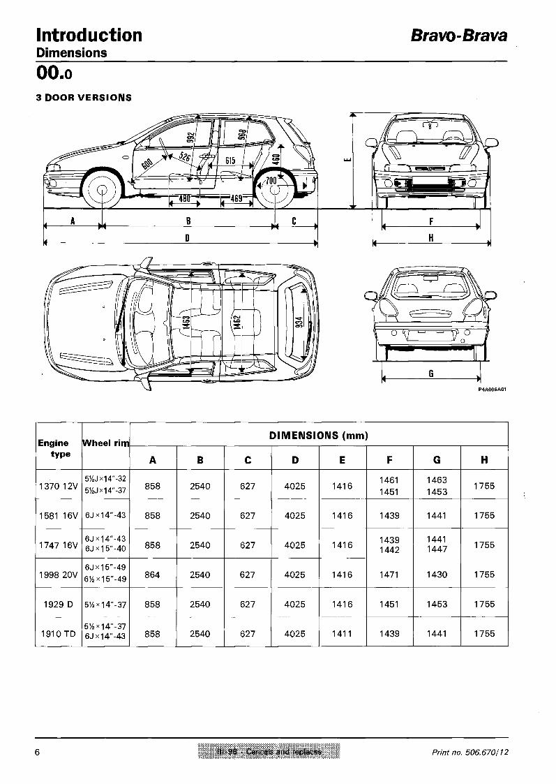
I n t r o d u c t i o n Bravo-Brava Dimensions O O . o 3 DOOR VERSIONS
Engine type
Wheel rim DIMENSIONS (mm)
Engine type
Wheel rim
A B C D E F G H
1 3 7 0 1 2 V 51AJx14"-32 51/2J*14"-37 8 5 8 2 5 4 0 6 2 7 4 0 2 5 1 4 1 6
1 4 6 1
1 4 5 1
1 4 6 3
1 4 5 3 1 7 5 5
1 5 8 1 1 6 V 6J*l4"-43 8 5 8 2 5 4 0 6 2 7 4 0 2 5 1 4 1 6 1 4 3 9 1 4 4 1 1 7 5 5
1 7 4 7 1 6 V 6JX14"-43 6JX15"-40 8 5 8 2 5 4 0 6 2 7 4 0 2 5 1 4 1 6
1 4 3 9 1 4 4 2
1 4 4 1 1 4 4 7 1 7 5 5
1 9 9 8 2 0 V 6JX15"-49 61/2x15"-49 8 6 4 2 5 4 0 6 2 7 4 0 2 5 1 4 1 6 1 4 7 1 1 4 3 0 1 7 5 5
1 9 2 9 D 51/2X14"-37 8 5 8 2 5 4 0 6 2 7 4 0 2 5 1 4 1 6 1 4 5 1 1 4 5 3 1 7 5 5
1 9 1 0 TD 51/2X14"-37 6Jx14"-43 8 5 8 2 5 4 0 6 2 7 4 0 2 5 1 4 1 1 1 4 3 9 1 4 4 1 1 7 5 5
6 III-96 - Cancels and replaces Print no. 506.670/12

Bravo-Brava I n t r o d u c t i o n Dimensions
Engine Wheel DIMENSIONS (mm)
type rim A B C D E F G H
1370 12V 5y2Jx14"-32 5J4Jx14"-37 858 2540 789 4187 1413 1461
1451 1463 1453 1741
1581 16V 51/2JM4"-37
6JX14"-43 858 2540 789 4187 1413 1451 1439 1453 1441 1771
1747 16V 51/4Jx14"-37 6Jxi4'-43 858 2540 789 4187 1413 1451 1439 1453 1441 1741
1929 D 51/4JX14"-37 858 2540 789 4187 1143 1451 1453 1741
1910 TD 5)4JX14"-37
858 2540 789 4187 1408 1451 1453 1741 1910 TD
6JX14'-43 858 2540 789 4187 1408 1439 1441 1741
Copyright by Fiat Auto 111-96 - Cancels and replaces 7

T e c h n i c a l d a t a Capacities
Bravo-Brava
O O . o
Capacities
f t Petrol Ss O.R. 95 Unleaded
Diesel
Unit
.1 • • • • I, r e 1370-1581 1747-1998
1910 TD-1929 D
Quantity dm3(|)
50
6 0
6 0
(kg)
5 0 %
( A )
1370 6(5,6B)
1581 7(6,7«)
1747 6,7(6,2B)
Tota l capac i t y of c o o l i n g system
1998 7.4(7.3B)
1929 D 7,6(7,4B)
1370 Petrol engines:
SELENIA 20K (SAE 10 W / 4 0 )
4 ,3 3,8
Tota l capac i ty
1581 4,5
1747 4,9 4 ,4
1998 5,5 4,9
1929 D 5,5 4,9 1370 4,1(3,9«) 3,7(3,5«)
Diesel engines
SELENIA Tu rbo Diesel (SAE 15 W / 4 0 )
1581 3,8(3,5») 3,4(3,1 • )
1747 4,3(3.9») 3.9(3,5 • )
Partial capac i t y (per iod ic rep lacement )
1998 5(4,5») 4,45 (4 • )
1929 D 4,9(4,2«) 4,4(3,8»)
a = T U T E L A ZC 75 Synt
b = T U T E L A G l / A
. 1 .
1370 1581-1747
1998-1929 D
1,7 1,5
1,8
* i a = TUTELA G l / A
b = K 8 5 4
0,8
0 ,08
b = TUTELA M R M 2 0 ,003
T U T E L A T O P 4 (270°C)
w / o u t A B S
0 ,40
Tota l capac i ty
w i t h A B S
0,455 (0,54)* (0,43)*
A R E X O N S
1 0 ° C
~ - 2 0 ° C
3%
5 0 %
1 0 0 %
2,5-5 (6,4 with headlamp washer)
( A ) Distil led water ( • ) Engine sump only ( • ) For versions w i th air cond i t ion ing (*) For 1998 20V versions (**) For 1929 D versions
8 X-96 - Cancels and replaces Print no. 506.670/10

S e r v i c e N e w s
Copyright by Fiat Auto 1 0 / 9 7 Fiat Auto S.p.A D.M.C. - M.P.S. - Servizi Post Vendita
Tecnologie Assistenziali
V a r i o u s m o d e l s
models: Rat Bravo-Fiat Brava • Fiat Marea - Fiat barchetta - Coupe Fiat
0010 T120 AA
A
00 15.97
CHANGING ENGINE OIL
Service literature update with new oil capacity figures
Cancels and replaces the subject in question published in Service News 4/97 through the variation of the figures for the Fiat Bravo TD, Fiat Brava TD and Fiat Marea TD
T Y P E OF PROBLEM
The oil capacity figures in the "Owner's Handbook" and the Service Manuals are not consistent with actual capacities of the engine.
OPERATIONS IN THE NETWORK
When changing the engine oil stick to the figures given below which update the corresponding ones in the Service Manual and the Owner's Handbook. Provide the Customer with appropriate information on the subject, as necessary.
Model/version Engine sump, filter and pipes (1st filling)
Engine sump Engine sump and oil filter
dm 3 Kg dm 3 Kg dm 3 Kg
Fiat Bravo 1.6 4,5 4,0 ' 3,5 3,1 3,8 3,4 Fiat Brava 1.6 4,5 4,0 3,5 3,1 3,8 3,4 Fiat Marea 1.6 4,5 4,0 3,5 3,1 3,8 3,4
Fiat Bravo 1.8 4,6 4,1 3,9 3,5 4,3 3,85 Fiat Brava 1.8 4,6 4,1 3,9 3,5 4,3 3,85 Fiat Marea 1.8 4,6 4,1 3,9 3,5 4,3 3,85
Fiat barchetta 4,7 4,2 3,7 3,3 4,0 3,6 Coupe Fiat 1.8 5,0 4,5 4,0 3,6 4,4 3,9
CARTA RICICLATA 100% RECYCLED PAPER 100%
00.15.97 Various models
0010 T 120 AA CHANGING ENGINE OIL
2/2
Model/version Engine sump. Engine sump Engine sump filter and pipes and oil filter (1st filling)
dm 3 Kg dm 3 Kg dm 3 Kg
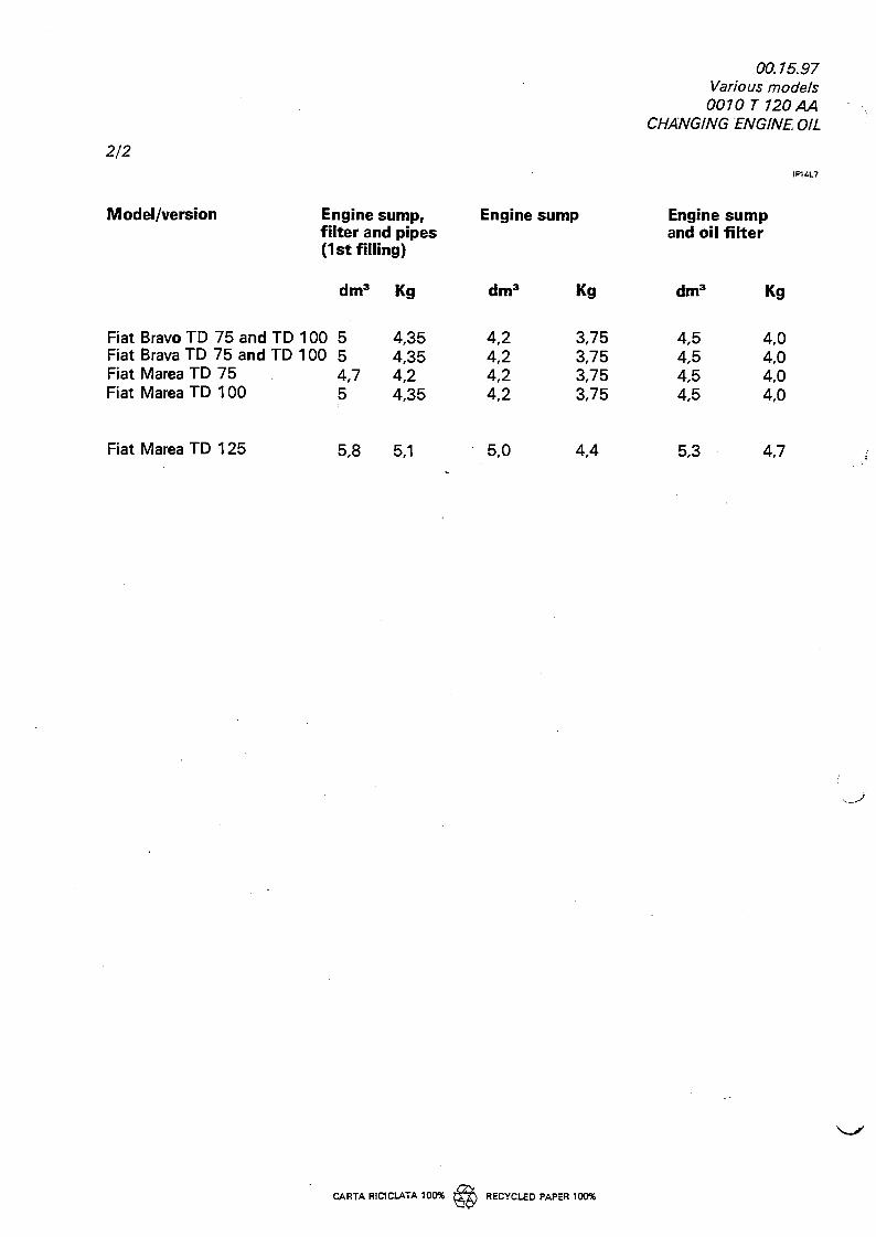
Fiat Bravo TD 75 and TD 100 5 4,35 4,2 3,75 4,5 4,0 Fiat Brava TD 75 and TD 100 5 4,35 4,2 3,75 4,5 4,0 Fiat Marea TD 75 4,7 4,2 4,2 3,75 4,5 4,0 Fiat Marea TD 100 5 4,35 4,2 3,75 4,5 4,0
Fiat Marea TD 125 5,8 5,1 5,0 4,4 5,3 4,7
CARTA RIC1CLATA 100% RECYCLED PAPER 100%

S e r v i c e N e w s
Copyright by Fiat Auto 4 / 9 7
a n o n
Fiat Auto S.p.A D.M.C. • M.P.S. • Servizi Post Vendita.
Tecnologie Assistenziati
V a r i o u s m o d e l s
models: Fiat Bravo-Rat Brava - Fiat Marea • Fiat barchetta • Coupe Fiat
0010 T 120 AA
A
CHANGING ENGINE OIL
service literature update with new oil figures.
00 15.97
T Y P E OF PROBLEM
The oil figures given in the "Owner's Handbooks" and the Service Manuals are not consistent with the actual engine capacities
OPERATIONS IN THE NETWORK
When changing the engine oil, refer to the figures given below which update the corresponding figures given in the Service Manual and the Owner's Handbook.
Please provide the Customer with suitable information on this subject, as appropriate.
Model/version
Fiat Bravo 1.6 Fiat Brava 1.6 Fiat Marea 1.6
Engine sump, filter and pipes (1st filling)
Engine sump
dm 3
4,5 4,5 4,5
Kg 4,0 4,0 4,0
dm 3
3,5 3,5 3,5
Kg
3,1 3,1 3,1
Engine sump and oil filter
dm 3
3,8 3,8 3,8
Kg 3,4 3,4 3,4
Fiat Bravo 1.8 Fiat Brava 1.8 Fiat Marea 1.8
4,6 4,6 4,6
4,1 4,1 4,1
3,9 3,9 3,9
3,5 3,5 3,5
4,3 4,3 4,3
3,85 3,85 3,85
Fiat barchetta Coupe Fiat 1.8
4,7 5,0
4,2 4,5
3,7 4,0
3,3 3,6
4,0 4,4
3,6 3,9
IF10D7

2/2
00.15.97 Various models 0010 T 120 AA
CHANGING ENGINE OIL
Model/version Engine sump, filter and pipes (1st filling)
dm 3
Fiat Bravo TD 75 and TD 100 4,7 Fiat Brava TD 75 and TD 100 4,7 Fiat Marea TD 75 and TD 100 4,7
Kg 4,2 4,2 4,2
Engine sump
d m 3
4,2 4,2 4,2
Kg 3,75 3,75 3,75
Engine sump and oil filter
dm 3
4,5 4,5 4,5
Kg
4,0 4,0 4,0
Fiat Marea TD 125 5,9 5,2 5,0 4,4 5,3 4,7

Bravo-Brava I n t r o d u c t i o n Characteristics of Fiat Lubricant products
O O . o Name of product
Description International designation Application
SELENIA SAE 15 W/40 Semi-synthetic multigrade engine oi l . Exceeds specifications API SH, C C M C - G 5 and UNI 20153
Temperature - 25°C + 40°C
VS MAX SAE 15 W/40 Mineral based mult igrade engine oi l . Exceeds specif icat ions API SG, C C M C - G 4 and UNI 20153
Temperature - 15°C -r 4 0 ° C
SELENIA d c ,„,,„„ Turbo SAE 15 W/40 Diesel
Semisynthetic, mult igrade engine oi l . Exceeds specif icat ions API CD, C C M C - P D 2 , UN I 20153
Temperature - 15°C -h 40 °C
VS MAX SAE 15 W/40 Diesel
Mult igrade mineral based engine o i l . Exceeds specif icat ions API CD, C C M C and UNI 20153
Temperature - 15°C h- 4 0 ° C
TUTELA ZC 80S SAE 80W EP oi l . Satisfies standards M I L - L - 2 1 0 5 and API GL4
Manual gearboxes and differentials
TUTELA ZC 90 Non EP SAE 8 0 W / 9 0 o i l , for manual gearboxes, conta in ing ant i-wear addit ives.
Gearboxes and non hy-po id differentials
TUTELA W 90/M DA Special SAE 8 0 W / 9 0 EP oi l for normal and sel f - lock ing differentials. Satisfies standards M I L - L - 2 1 0 5 D and API GL5
Hypoid di f ferent ials Sel f - lock ing di f ferent ials. Steering boxes
TUTELA Gl/A "DEXRON I I " type oil for automatic transmissions Automat ic gearboxes. Power assisted steering
TUTELA CVT Universal Oil for con t inuous variat ion automatic transmissions. Cont inuous var iat ion automatic transmissions
TUTELA J0TA1 Lithium soap based grease, consistency NLGI = 1 Greasing the vehicle except for components particularly exposed to water requiring special greases
TUTELA MRM2 Water-repel lant, l i th ium soap based grease conta in ing m o lybdenum disulphide, consistency NLGI = 2 Constant ve loc i ty jo in ts
TUTELA MR3 Lithium soap based grease, consistency N L G I = 3 Wheel hub bearings, st. rod, various componen ts
TUTELA PLUS 3 (240 C) Synthetic f l u id , F.M.V.S.S. n° 116 DOT 3 ISO 4925 , C U N A NC 956-01
Hyd . brakes and hy-draulical ly op. c lutches
TUTELA TOP 4 (270 °C) Synthetic f l u id , F.M.V.S.S. n° 116 DOT 4 ISO 4925 , C U N A NC 956-01
Hyd . brakes & hydrau l i -cally op. c lu tches
K 854 Lithium soap based grease, consistency NLGI = 000, c o n taining mo lybdenum disulphide
Rack and p in ion steering boxes
SP 349 Special grease compat ible w i t h brake f lu id Load propor t ion ing valve Load propor t ion ing valve rod bush
Arexons DPI Mix. of a lcoho l , H20 & surf. act. agents C U N A NC 956-11 To be used neat or d i lu t ed in windscreen washer systems
Paraflu" Mono-e thy lene glycol based anti-freeze for coo l ing system, CUNA NC 596 - 16
Cool ing circui ts. Percentage to be used 50% up to - 3 5 ° C
Diesel Mix Arexons Additive for diesel fuel w i th protective action for diesel engines To be mixed w i t h diesel fuel (25 cc per 10 litres)
Copyright by Fiat Auto 9

T e c h n i c a l d a t a Engine
Bravo-Brava
O O . i o
CHARACTERISTICS
12V 16V 20V
Cycle
Timing
Type of fuel system
OTTO 4 stroke
single overhead camshaft twin overhead camshaft
integrated electronic injection/ignition
• • • Number of cylinders
f - 0 Cylinder liner (bore) mm 82 86,4 82 82
Stroke mm 64,87 67,4 82,7 75,65
Q b i b J | Capac ity cc 1370 1581 1747 1998
Compression ratio
9,85±0,15 10,15±0,15 10,3±0,15 10±0,15
Max power EEC
kW (CV)
59 59(*) (80) (75)C)
76 66(*) (103) (90) (*)
83 (113)
108 (147)
rpm 6000 5750 6000(*) 5800 6100
daNm (kgm)
11,2 (11,4)
14,4 14(*)
(14,7) (14,3)0 15,4
(15,7) 18,6 (19)
Max torque EEC
rpm 2750 4000 4400 4500
( * ) F o r s p e c i f i c m a r k e t s
10 VII-95 - Cancels and replaces Print no. 506.670/02

Bravo-Brava T e c h n i c a l d a t a Engine: typical curves
O O . i o CV kW
I H 1 1 1 1 1 I 1000 2000 3000 4000 5000 6000 7000
rpm
Engine power curves obtained by E E C method
The power curves illustrated can be obtained with the engine overhauled and run in, without a fan and with a silencer and air filter fitted at sea level.
Copyright by Fiat Auto 11

T e c h n i c a l d a t a Bravo-Brava Engine: cylinder block/crankcase, crankshaft and associated components O O . i o
DESCRIPTION Values in mm
L-»N«- L1-*H«-
Main bearing supports
21,72-21,80
0 56,705-56,718
22,14-22,20
54,507-54,520
21,72-21,80
56,705-56,718 63 ,705-63 ,718
0. 01
BP • J Auxiliary shaft bush housings
38,700-38 ,730
02 35,036-35,066
0 - 0
Cylinder bore 0
82,000-82,010 86 ,400-86 ,410 82 ,000-82 ,010
82 ,010-82 ,020 86 ,410-86 ,420 82 ,010-82 ,020
82 ,020-82 ,030 86 ,420-86 ,430 82 ,020-82 ,030
12 Print no. 506.670

S e r v i c e N e w s
Copyright by Fiat Auto 1 / 9 6 F i a t A u t o s.p.A D.M.C. - M.P.S. - Servizi Post Vendita
Assistenza Tecnica
F i a t B r a v o - F i a t B r a v a i s s i i e v
1028 C 301 AA ENGINE PISTONS rectifying diameter value indicated in the Service Manual
10 05.96
A l With reference to what is stated on page 13 of section 00 in the Service Manual Print no. 506.670, we wish to point out that the exact values for the engine piston diameters for the model in question are as follows:
A 86,352 - 86,362
B 86,359 - 86,371
C 86,368 * 86,378
Please make a note, by hand, of the correct figures in the above mentioned publication.
IF43A6


Bravo-Brava T e c h n i c a l d a t a Engine: cylinder block/crankcase. crankshaft and associated components
O O . i o
12V 16V 20V
DESCRIPTION Values in mm
0
X 12,5
81,952-81,962 5(, 83 ,352-J3 ,362
B 81,959-81,971 0,359^0'^
81,968-81,978
13,2
83,368-83,378
12,5
81 ,952-81 ,962
81 ,959-81,971
81 ,968-81 ,978
Piston 0 > 0,4
Difference in weight between pistons ±5 g
0,038 0,058
3-1 Of Piston Cylinder bore 0 B 0,039 - 0,061
0,042 + 0,062
Gudgeon pin housing
0 20,002-20,007 21,997-22,001 20 ,002-20 ,007
4, 0 19,996-20,000 21,990-21,995 19 ,996-20 ,000
Gudgeon pin 0 0,2
4 -3 Gudgeon pin - Housing 0,002 H- 0,011
1,540-1,560
2 Piston ring grooves 8 1,530-1,550
3 ,020-3,040
1,525-1,545
1,510-1,530
3 ,010-3 ,030
1,540-1,560
1,530-1,550
3 ,020-3 ,040
1 ,520-1 ,540
1 ,510-1 ,530
3 ,010 -3 ,030
Copyright by Fiat Auto 13

T e c h n i c a l d a t a Bravo-Brava Engine: cylinder block/crankcase, crankshaft and associated components O O . i o
20V
DESCRIPTION Values in mm
. 0 - 1 " ^ 1 1 1,470*1,490 1,475*1,490
. 0 - 1 i—I X 1,475*1,490 1,470*1,490 1,475*1,490
. 0 - 1 LlT 3 2,935*2,945 2 ,975*2 ,990
Piston rings 0 ^ > 0,4
Piston rings Oi 0 Piston ring grooves
0,050*0,090 0,035-0,075 0,050*0,085 j 0,030^0,065
Piston rings Oi 0 Piston ring grooves hi- 2 0,040*0,075 0.020-0,060 0,040*0,075 ; 0,020^0.055
— - 3 0,075-0,105 0,065-0,095 0,030-0,065 0,020-0.055
Opening at end of 5_1 u^i p piston rings
-»f-H- in cylinder bore *
1 0,250*0,500 0,200*0,450 0 ,300*0 ,500 Opening at end of
5_1 u^i p piston rings -»f-H- in cylinder bore * 0,300*0,500 0,250*0,500 0 ,300*0 ,500
Opening at end of 5_1 u^i p piston rings
-»f-H- in cylinder bore *
3 0,400*1,400 0,400*1,400 0 ,250*0 ,450 0 ,250*0,500
Small end bush ] w f -^- 1 or pin housing
6 ) w I I 0 2 Big end bearing
^ r1 4- housing *
0 1 22,939*22,972 23,939*23,972 22 ,939*22 ,972 Small end bush ] w f -^- 1 or pin housing
6 ) w I I 0 2 Big end bearing
^ r1 4- housing *
0 2 44 ,000*44 ,012 48,630*48,646 53,897*53,909 51 ,354*51 ,366
14 Print no. 506.670

Bravo-Brava T e c h n i c a l d a t a Engine: cylinder block/crankcase, crankshaft and associated components
O O . i o
112V !&I5| 16V 20V
DESCRIPTION Values in mm
01 23,007*23,027
02 20,006*20,012
Small end bush
24,016*24,041
22,004*22,010
23 ,007*23,027
20 ,006*20 ,012
4-7 %g Gudgeon pin Small end bush 0.006- 0,016 0 .009-0 020 0 006-0 .020
7-6 Small end bush Bush housing 0 035 -0 088 0 , 0 4 4 - 0 1 0 2 0 035 0 088
Main journals
01
8 0i ^ i r l r "
•I N
3
52,994*53,000 50,790*50,800 52,994*53,000 59 ,994*60 ,000
52,988*52,994 50,780*50,790 52,988*52,994
52,982*52,988 52,982*52,988
Crank pins 0 2
40,884*40,890 45 ,513*45,523 50,799*50,805
40,878*40,884 45,503*45,513 50,793*50,799
40,872*40,878 50,787*50,793
59 ,988*59 ,994
59 ,982*59,988
48 ,238*48 ,244
48 ,232*48 ,238
48 ,226*48232
L
Li
26,975*27,025
26,575*26,625 26 ,575*26 ,625
Crankshaft bearings 1,836*1,840 1,840*1,844 1,836*1,840
1,839*1,843 1,845*1,849 1,839*1,843
1,842*1,846 1 ,842*1846
0 < 0,254 - 0,508
9-8 Of Crankshaft bearing Main journals 0.025-0 .052 0.019 0 050 0.025*0.052
Copyright by Fiat Auto 15

T e c h n i c a l d a t a Bravo-Brava Engine: cylinder block/crankcase, crankshaft and associated components O O . i o
D E S C R I P T I O N
llg5t 16V 20V
D E S C R I P T I O N Values in mm
(
1 0 * p i 0->l—W- ^~
^ f A
^ f\—in l-rh -iff 1 t 1
1,536*1,540 1,535*1,541 1,527*1,531 1,536*1,540 (
1 0 * p i 0->l—W- ^~
w r u r a n K s n a n i m 1 bearings L < P B 1,539*1,543 1,540*1,546 1,530*1,534 1,539*1,543
(
1 0 * p i 0->l—W- ^~
I I c 1,542*1,546 - 1,533*1,537 1,542*1,54
(
1 0 * p i 0->l—W- ^~
0 i a ^ F < 0,254 - 0,508
- n o Q p Big end bearings-l u ° -44 - Main journals 0 ,030-0 ,056 0 ,025*0,063 0 ,030*0 ,056
1 1
Thrust q \ _ r - | washers ^ ,2 ,342*2,358 2,310*2,360 2 ,342*2 ,358
1 1
0,127
1 1 - 8 ^ p Crankshaft end float j
0,059 * 0,161 ! 0 055*0 ,265 0 ,059-0 ,161
16 Print no. 506.670

Bravo-Brava T e c h n i c a l d a t a Engine: auxiliary shaft
DESCRIPTION
O O . i o
i s 16V
Values in mm
23
# 1 ^
Bushes for auxiliary shaft in housing
35,664 - 35,684
32,000 - 32,020
24 02 0- 0,
Auxiliary shaft bearings
0,
35,593 - 35,618
31,940 - 31,960
23-1 Bushes for shaft Cylinder block seats must be an interference fit
24-23 ^ f Shaft bushes Bushes
0,
0,
0,046 - 0,091
0,040 - 0,080
Copyright by Fiat Auto 17

T e c h n i c a l d a t a Bravo-Brava Engine: cylinder head assembly and valve gear components O O . i o
1 8
17
1 3 I 1 6 . |
1 5 • ^
20
19
1 4
\12V 16V j^9|l6V 20V
DESCRIPTION Values in mm Camshaft supports in cylinder head
lESL i2v
i2bH i i i [__n__ri "0
0 26,045*26,070
20V
L (•) 19,100*19,150
26,045*26,070
19,100*19,150
i Valve guide bore in cylinder head 0 12,950 * 12,977
• Q 45° ± 5' Valve a bore ® 45° ± 5'
about 2
Volume of combustion 3
chamber in cylinder cm head
37 39
(*) Measurement of cap
18 /
Print no. 506.570

Bravo-Brava T e c h n i c a l d a t a Engine: cylinder head assembly and valve gear components
O O . i o
1 8 9 12V 1} 16V l^p)l6V m 20V
DESCRIPTION Values in mm
n — .nj—in_. —i_r~<-i—I_T -T—i -
« 5iP Tap. housing in cyl. head 0 14,000*14,027 33 ,000*33 ,025
13
0 1 ^ T ] 7,022 - 7,040
Valve guide 'HQ
02'
- 0 2
13,010 - 13,030
02 > 0,05 - 0,10 - 0,25
13-12 Valve guide Bore in cylinder head
• Q
(S3 0,033 - 0,080
1 4
01 0 , 6,982-7,000 6,975*6,990
HQ 0 , 30,200*34,500 33,400*37,700 29 ,900*30 ,200
a 45°30' ± 5' Valve
S3 0 , 6,982*7,000
0 , 34,500*35,700
6 ,974*6,992
29 ,750*30,050 27,900*28,200
6 ,960*6,975
25 ,900*26 ,200
a 45°30' ± 5'
14 -13 V a ' V e
0,022-0,058 Valve guide
0,022*0,058 0,030-0,066
0,032-0,065
0,047-0.080
15
Pi 9,61*10,6 daN
3 a Hi
1 T H 2 29,5
P2 20,11-22,07daN
Internal valve spring H 2 20
11,08*12,07daN
29,5
21,58*23,54daN
20
1 6 Hi
h i
33,35*37,28 daN
37
55,42*60,53 daN
External valve spring H, 28,1
23,54*25,7 daN 27,07*29,43 daN
32 34
46*49,93 daN 48 ,46*52 ,38 daN
23,5 24,5
Copyright by Fiat Auto 19

T e c h n i c a l d a t a Bravo-Brava Engine: cylinder head assembly and valve gear components O O . i o
DESCRIPTION Values in mm
Camshaft bearings
16V 01
0, 0 2 03 04 0.5
17a 02
03
17b j 0
} 3H2V ) £ ^ | an i6v 04
05
iBpi 20V ,0 ,0 ,0 i0 i0 i0
0 26,000*26,015
1 7 c -||M Ifll UjUgJ 19,250*19,330
29,944*29,960
52,400*52,415
52,800*52,815
53,200*53,215
53,600*53,615
26,000-26,015
19,250*19,330
1 7 a J E i 1 7 b O Cam lift
S 3
8,9 8,5 7,5 8
Camshaft bushes Cylinder head supports
radial 0 ,030*0 .070 0,030-0,070
axial 0 ,100*0 ,230 0,100 - 0,230
20 Print no. 506.570

Bravo-Brava T e c h n i c a l d a t a Engine: cylinder head assembly and valve gear components
O O - i o
12V 16V fmfHiev 120V
DESCRIPTION Values in mm
01 29,989*30,014
0 4 | 0 5 0 2 52,445*52,470
18
r-iTT_^-jTJT_^ru^-j-ijnJ--vjTjn *-n-n^r\jT-ri^\_ju~i-nj^ Camshaft bearings in camshaft housing
0 3 52,845*52,870
0 4 53,245*53,270
0 5 53,645*53,670
n —~-r-ir-in_ —ur -1—
BB3PB Tappet housings 0 — 0 k—
30,000*33,025
17 18 ^ jp Camshaft bearings Camshaft housing supports 0,030-0,070
19 c ^ ^ b Tappet 0 13,972*13,984 32,959*32,975
19 -12 Oj p Tappet ousing in cylinder head 0,016*0,055 0,025 - 0,066
19-18 Tappet - Housing in camshaft housing 0,025-0,066
17-20
clearance for timing check
i
HQ 0,45
0,45
operational clearance
HQ Hydraulic tappets
Copyright by Fiat Auto 21

T e c h n i c a l d a t a Bravo-Brava Engine: cylinder head assembly and valve gear components O O . i o
TIMING DIAGRAMS
Timing angles
12V I B 16V I^P)l6V 20V
A
Inlet HQ
opens before TDC 8° 4° 0° 9°
after TDC
B
Inlet HQ closes after BDC 25° 34° 27° 49°
C
Exhaust ® opens before BDC 29° 36° 29° 27°
D
Exhaust ® closes after TDC 7° 2° 2° 2°
22 Print no. 506.670

Bravo-Brava T e c h n i c a l d a t a Engine: counter-balance shaft
O O . i o
• 1998 120V
D E S C R I P T I O N Values in mm
2 5 Counter-balance shaft operation through oil pump driven gear
2 7 0 2 - O U 0 1 20 01
02 Ball bearings for counter-balance shaft
19,900 + 20,000
46,989 - 47,000
|0 2 5
10 10 Counter-balance shaft bearings
H i 0 19,980 - 19,993
Bear, seats in cyl. block-cr/case 0 46,975 + 47,000
o-? i d id c i , B a l 1 bearings * / - ' ^ [T vi Cylinder block seats +0,011 + - 0,025
2 5 - 2 7 ^ Shaft bushes Ball bearings +0,020 + - 0,003
Copyright by Fiat Auto 23

T e c h n i c a l d a t a Bravo-Brava Engine: lubrication O O . i o
LUBRICATION - Description
I^9|i6v
LUBRICATION - Description Values in mm
Engine lubrication system forced feed via lobe gear pump with cartridge filter in series
Oil pump lobe gears
Pump operated through crankshaft
Oil pressure relief valve incorporated in crankshaft front cover
\ —* between pump casing " housing and driven 0.080 - 0,186
£ between the upper side
~ of the gears and the pump cover
0,025 - 0,061 0,025 -i- 0,070
Full flow filter cartridge
Insufficient oil pressure sender unit electrical
© © A Operating pressure at a temperature of 100°C
idling 1 bar at 4000 rpm 4 bar 3,43 - 4,93 bar
6,28 - 7,03 daN
^ I Hi u
Dil pressure relief valve spring 1 36
24 Print no. 506.670

Bravo-Brava T e c h n i c a l d a t a Engine: lubrication
O O . i o
1 6 V
LUBRICATION - Description Values in mm
Engine lubrication system forced feed via geared pump
with cartridge oil filter in seriew
Oil pump: type gears
Pump operated through auxiliary shaft
j Oil pressure relief vaive incorporated in oil pump
Full flow filter cartridge
insufficient oil pressure sender unit electrical
between the edge of the gears and the pump cover
0,110 - 0,180
between the upper side of the gears and the pump cover
0,040 * 0,106
01-02 0,015 - 0,048
01-02 0,016-0,048
between the drive gear and the driven gear 0,30
Operating pressure at a temperature of 100°C
idling > 1 bar
at 4000 rpm > 3,7 bar
Pi
kit Hi
T~H2 P2
H2
6,52 - 6,82 daN
22,5
6,92 - 7,21 daN
21
Copyright by Fiat Auto 25

T e c h n i c a l d a t a Engine: lubrication
Bravo-Brava
O O . i o
LUBRICATION Values in mm
Engine lubrication system forced feed, via lobe geared pump with cartridge oil filter in series
Oil pump gears, located in the crankshaft front cover
Pump operated through chain operated by crankshaft
Oil pressure relief valve incorporated in crankshaft front cover
Full flow filter cartridge
Insufficient oil pressure sender unit electrical
• ^ _ ^ ^ ^ J L between the edge of I I : fl^HI the gears and the ^ • 2 ^ 5 1 ^ 0 pump casing
0,110 - 0,180
1 B : "IB flH| 1 ^ between the upper ^ S H ^ 2 | ^ J e c 'ge of the gears and ^ ^ ^ H B j ^ the pump cover
0,016 * 0,086
0\ 0 between the drive gear and the -H-H- driven gear
©<§> Jt Operating pressure at a temperature of 100°C
idling 1 bar at 4000 rpm 4 bar
11 ,73 -12 ,51
9 I Hi Oil pressure relief valve spring ^ 1 35
26 Print no. 506.670

Bravo-Brava T e c h n i c a l d a t a Engine: cooling system - fuel system
O O . i o
COOLING S Y S T E M i f i h i s v I ^ P l i e v 20V
Cooling circuit coolant circulation via centi, radiator, expansion tank and electric fan operated by thermostatic switch
Water pump operation through belt
a 1 s t s t a g e 90° -e- 94°C
~ p \ Thermal v " y o J ^1 switch 2nd stage 95° + 99°C ( • )
fill to engage U fan (*) 1st stage
••• IStODl 85° - 89°C
• v p J v / 2nd stage 90° - 94°C ( • )
opening 81° -s- 85°C
Engine coolant thermostat m a x open.ng 1 0 r - 1 0 5 ° C 99°+103°C 98°-102°C 101 o-M05 eO
valve travel 9,5 mm >7,5 mm 9,5 mm
Fitting clearance between 0> p impeller vanes and pump casing - * H « - 0,3-1,1 mm
Press. for checking rad. water tightness 0,98 bar
Pressure for checking calibration of exhaust spring on expansion tank cap 0,98 bar
(•) For versions with air conditioning (*) For the 1747 16v version the electric fan is operated by the control unit F U E L S Y S T E M
Type
Bosch Monomotronic SPI integrated
electronic injection/ ignition
Weber-Marelli I.A.W
MPI integrated electronic injection/ ignition
HITACHI MPI integrated
electronic injection/ ignition
Bosch Motronic integrated electronic injection /ignition Motronic
Pump Electrical, immersed in tank
Capacity 5*120 l/h
Fuel pressure regulator setting 1 bar 3 bar
CHECKING IDLE CONCENTRATION OF POLLUTANT EMISSIONS CO (%) HC (p.p.m.) C 0 2 (%)
Upstream of the catalytic converter 0,4 H- 1 <600 ^ 1 2
Downstream of the catalytic converter ^0,35 <90 > 1 3
Copyright by Fiat Auto 27

T e c h n i c a l d a t a Engine: fuel system O O . i o
Bravo-Brava
INTEGRATED ELECTRONIC INJECTION/ IGNITION S Y S T E M COMPONENTS
Electronic control unit Bosch 0.261.203.868
Butterfly casing Bosch 0.438.201.523
TDC and rpm sensor Bosch 0.281.002.102
Fuel vapour solenoid valve Bosch 0.280.142.300
Detonation sensor Bosch 0.261.231.007
Coolant temperature sensor Bosch 0.280.130.026
Electric fuel pump Bosch 0.580.453.514
Lambda sensor Bosch 0.258.008.688
Fuel filter Bosch
28 Print no. 506.670

Bravo-Brava T e c h n i c a l d a t a Engine: fuel system
O O . i o
COMPONENTS OF INTEGRATED ELECTRONIC I N J E C TION-IGNITION S Y S T E M
Electronic control unit I.A.W.- IAF.13
I.A.W. - IAF.17 (*) I.A.W. - IAF.23 (•)
Absolute pressure sender unit (barometric capsule) M.Marelli PRT 03/02
Fuel vapour control solenoid M.Marelli/SIEMENS EC1
Throttle case M.Marelli 54 CFA 26
Idle adjustment actuator B02/01
Injector M.Marelli IWP 001
Air temperature sender unit JAEGER ATS-04/01
Fuel pressure regulator M.Marelli RPM 40
Coolant temperature sender unit JAEGER 401930-01
Top dead centre and rpm sensor JAEGER CVM 01
Throttle valve position sensor (potentiometer) M.Marelli PF 1C
Dual relay activating fuel pump and injection-ignition control unit BITRON NDRS 240 103/00
Electric fuel pump WALBRO MSS 071/03
Lambda probe NTK 0ZA112-A1
Fuel filter Bosch A.450.024.262
Timing sensor JAEGER SFA 200
Ignition coils COOPER BAE 92 OA
( * ) For specific markets
( • ) For version w i t h automatic transmission
Copyright Fiat Auto IX-95 - Supersedes prev. version 2 9

T e c h n i c a l d a t a Bravo-Brava Engine: fuel system O O . i o
COMPONENTS OF INTEGRATED ELECTRONIC INJECTION-IGNITION S Y S T E M
| ^ ^ ( l 6 V
Electronic control unit HITACHI MFI-0
Air flow meter (hot wire) HITACHI BX 106833
Injector HITACHI G L 212264
Fuel pressure regulator RPM 40/3 bar
Coolant temperature sensor Bosch 0.280.130.055
Electric fuel pump WALBRO MSS 071/01
Lambda probe NTK 0ZA112-A2
Fuel filter G.M. 25121074
Idle actuator HITACHI G L 326716
Throttle valve position sensor (potentiometer) HITACHI G L 326686
Fuel vapour control solenoid DELCO REMY 1997199
Power module HITACHI GE 107765
Top dead centre and rpm sensor HITACHI GE 108101
Knock sensor NGK KUE-03
Timing sensor Bosch B.232.070.023
Throttle case HITACHI GL 007582
30 X-95 - Supersedes previous version Publication no. 506.670/04

Bravo-Brava T e c h n i c a l d a t a Engine: fuel system
O O . i o
INTEGRATED ELECTRONIC INJECTION/ IGNITION S Y S T E M COMPONENTS
! 0 p 3 | 20V
Injection/ignition system electronic control unit Bosch 0.261.203.994
Butterfly casing N.D.
Fuel pressure regulator Bosch 0.280.160.515
Injector Bosch 0.280.1 50.443
Idle adjustment actuator Bosch 0.280.140.553
Electric fuel pump Bosch 0.580.453.408
Air flow meter Bosch 0.280.217.111
Fuel filter Bosch A.450.024.262
Butterfly valve position sensor (potentiometer) Bosch 0.280.122.001
Coolant temperature sensor Bosch 0.280.1 30.026
Lambda sensor Bosch 0.258.003.466
Fuel vapour solenoid valve Bosch 0.280.142.300
Detonation sensor Bosch 0.261.231.095
Hall effect injection timing sensor Bosch 0.232.101.026
Intake air temperature sender unit Bosch 0.280.130.073
T D C and rpm sensor Bosch 0.281.002.102
Copyright by Fiat Auto 31

T e c h n i c a l d a t a Engine
Bravo-Brava
O O . i o
CHARACTERISTICS
TD
Cycle
Timing
Type of fuel system
DIESEL 4 stroke
single overhead camshaft
Indirect mechanical injection
• • • Number of cylinders
1-0 Cylinder liner (bore) mm 82,6 N.D.
Stroke mm 90 N.D.
\ Capac ity cc 1929 N.D.
= 9 Compression ratio
21 ± 0,5 N.D.
Total volume of combustion chamber cc 24,11 N.D.
kW (CV)
48 (65)
Max power EEC
rpm 4600
daNm (kgm)
11,9 (12,1)
Max torque EEC
rpm 2000
N.D.
N.D.
N.D.
N.D.
32 Print no. 506.670

Bravo-Brava T e c h n i c a l d a t a Engine: typical curves
O O . i o
N m kgm CEEDIN 120-1 110¬100-90 J
1*1 11¬10-9 J
3000 4000 5000 rpm
Test Time Load speed in on the (rpm) minutes brakes
800-1000 10' no load 1500 10' no load 2000 10' no load
Test bench cycles of overhauled engines
During the .bench test of the overhauled engine it is not advisable to run the engine at maximum speed, but to stick to the figures given in the table; complete the running in of the engine in the vehicle.
Engine power curves obtained by E E C method The power curves illustrated can be obtained with the engine overhauled and run in, without a fan and with a silencer and air filter fitted at sea level.
Copyright by Fiat Auto 33

T e c h n i c a l d a t a Bravo-Brava Engine: cylinder block/crankcase, crankshaft and associated components O O . i o
DESCRIPTION Values in mm
L1 23,100 -s- 23,200
0 56,717 - 56,735 Main bearing supports
21,720 - 21,800
56,705 - 56,718
- 0 Cylinder bore 0
A I F
~c
82,600 - 82,610 82,000 - 82,010
82,610 - 82,620 82,010 H- 82,020
82,620 - 82,630 82,020 - 82,030
X 15 10
3 3
82,520 - 82,555 81,930 - 81,940
82,530 - 82,540 81,940 - 81,950
82,540 - 82,550 81,950 - 81,960 Piston
0 0,4
3-1 Piston projection 0,367 + 0,832
Diff. in weight between pistons
± 5 g
3-1 S l £ Piston Cylinder bore
0,070 * 0,090 0,060 -s- 0,080
3 4 Print no. 506.670

Bravo-Brava T e c h n i c a l d a t a Engine: cylinder block/crankcase, crankshaft and associated components
O O . i o
TD
DESCRIPTION Values in mm
•H*
Gudgeon pin housing 0 24,994 - 24,999 25,991 + 25,996
Piston ring grooves
2,175 -5- 2,205 2,675 H- 2,705 (*)
2,010 - 2,030
3,020 - 3,040
0 24,987 H- 24,991 25,982 + 25,987
Gudgeon pin 0 0,2
4-3 Gudgeon pin - Housing 0,003 -5- 0,012 0,004 + 0,014
0 =4
2,075 - 2,095 2,575 - 2,595 (**)
1,978 - 1,990 1,970 - 1,990
2,975 - 2,990 2,975 - 3,010 Piston rings
0 0,4
0,080 - 0,130 <**)
5.3 ^ P Piston rings Piston ring grooves
0,020 - 0,052
0,030 - 0,065
0,020 - 0,060
0,010 - 0,065
0,300- 0,500 0 ,200- 0,400 ^ Opening at end of
5-1 t j - fT piston rings in cylinder bore
0,300 - 0,500 0,250 - 0,500
0,250 0,500 0,250 -s- 0,500
(*) Measured at the 79.6 mm diameter (**) Measured 1.5 mm f rom outside edge
Copyright by Fiat Auto 35

T e c h n i c a l d a t a Bravo-Brava Engine: cylinder block/crankcase, crankshaft and associated components O O . i o
DESCRIPTION Values in mm
Small end bush or pin housing
0 2 Big end bearing housing
01 26,939-26,972
02 53,897 -i- 53,913
28,939-28,972
53,897 - 53,909
rence in weight between con rods ± 2,5 g
01 27,020 - 27,060 29,018 - 29,038
02 25,004 - 25,009 26,006 - 26,012
Small end bush
Gudgeon pin Small end bush 0,013 - 0,022 0,019 - 0,030
7-6 r ^ Small end bush Bush housing 0,048 - 0,121 0,046 - 0,099
8
Main journals
01 _2
3
52,995 - 53,004 52,994 - 53,000 52,986 - 52,995 52,988 - 52,994
52,982 - 52,988
Crank pins 0 2
A_ B_ C
50,796 - 50,805 50,799 - 50,805 50,787 - 50,796 50,793 - 50,799
50,787 - 50,793 _ L L1
27,975 - 28,025 26.575 - 26.625
36 Print no. 506.670

Bravo-Brava T e c h n i c a l d a t a Engine: cylinder block/crankcase, crankshaft and associated components
O O . i o
TD
DESCRIPTION Values in mm
Crankshaft bearings 1,839 + 1,843
1,843 - 1,847
1,836 H- 1,840
1,839 + 1,843
1,842 * 1,846
0 < 0,254 - 0,508
9-8 %g Crankshaft bearings Main journals 0,027 -r 0,062 0,025 - 0,052
10
O ) Big end bearings
1,528 + 1,532 1,527 + 1,531
1,533 - 1,537 1,530 - 1,534
1,533 + 1,537
0 0,254 - 0,508
10 -8 ^ f Big end bearings Main journals 0,028 - 0,061 0.030 - 0,056
11
Thrust washers 2,310 - 2,360 2,342 - 2,358
0,127
11 -8 Crankshaft end float 0,055 - 0.305 0,059 - 0,179
Diagram showing fitting of connecting rod-piston assembly and direction of rotation in engine
1. Projection on piston crown
2. Area where matching number of cylinder bore to which connecting rod belongs is stamped
The arrow shows the direction of rotation of the engine as seen from the timing side
Copyright by Fiat Auto 37

T e c h n i c a l d a t a Bravo-Brava Engine: cylinder head assembly and valve gear components O O . i o
DESCRIPTION Values in mm
n Valve guide bore in cylinder head 0 13,950 -s- 13,977
HQ 45° ± 5' a
® 45° ± 5'
Valve seats about 2.7
Camshaft bearing housings in cylinder head 0, 43,020 - 43,040
|j 01 |j 02 ||g4 p_i-i_j-i_JT_JT-i-i -JT_rT-j-^
LrT_n_r - ,- j _i-JT_n- ,~i-n^
0 , 25,545 -s- 25,570
0 , 24,045 - 24,070
0 , 43,020 - 43,040
L* 18,950 - 19,030
0 26,045 + 26,070
p_n_fL_H__n:
L Camshaft supports
"0
19,100 - 19,150
n n n T L .
Tap. housing 0 37,000 - 37,025
(*) Measurement of cap
38 Print no. 506.670
Bravo-Brava T e c h n i c a l d a t a Engine: cylinder head assembly and valve gear components
O O . i o
TD
DESCRIPTION Values in mm
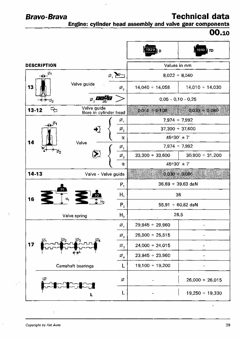
13
0 , ^ 3 8,022 + 6,040
Valve guide 0 , 14,040 + 14,058 14,010 + 14,030
0 2 M 0,05 - 0,10 - 0,25
1 3 - 1 2 ^ Valve guide Bore in cylinder head 0,061 -s- 0,108 0,033 - 0,080
1 4
01 0 i 7,974 - 7,992
ft Li
HQ 0 , 37,300 + 37,600
a 45°30' ± 7' Valve
02 §3 7,974 - 7,992
0 , 33,300 - 33,600 30,900 - 31,200
a 45°30' ± 7'
1 4 - 1 3 Valve - Valve guide 0,030 - 0,066
1 6
Pi 36,69 -e- 39,63 daN
Hi
Valve spring
i l l H 1 36
H2 55,91 - 60,82 daN
H, 26,5
0, 29,945 - 29,960
0 , 25,500 H- 25,515
1 7 0 , 24,000 - 24,015
0, 23,945 - 23,960
Camshaft bearings 19,100 - 19,200
J0 0 26,000 - 26,01 5
19,250 + 19,330
Copyright by Fiat Auto 39

T e c h n i c a l d a t a Bravo-Brava E n g i n e : c y l i n d e r h e a d a s s e m b l y a n d v a l v e g e a r c o m p o n e n t s
O O . 1 0
DESCRIPTION Values in mm
1 7 - 1 2 ^ f radial 0,030 - 0,070
axial 0,070 - 0.250 0,100 - 0,230
17 HQ 9,7 8,5
Cam lift ® 9,7 8,5
. n —^J-U-IT-L
-»l0k-Tappet 0 36,975 - 36,995
1 9 - 1 2 ^ p Tappet - Cylinder head 0,005 - 0,050
. n n r i T L OA — U L-l c u -20 s ^ m m S h i m
3,25 - 4,70
1 7 - 2 0
clearance for timing check • Q 0,50
m 0,50
1 operational clearance
• e 0.30 ^ 0,05 pffiilP li i i it l l
® 0,35 = 0,05
40 Print no. 506.670

Bravo-Brava T e c h n i c a l d a t a Engine: cylinder head assembly and valve gear components
O O . i o
DESCRIPTION DESCRIPTION Values in mm
2 1 a - 2 1 b Camshaft supports p_r-i_r-i_rTjT_i-i_rT_rT-j^^ 0 23,990 - 24,01 5 -
29,990 + 30,015 -
17-21 a Q p Camshaft 1 7 - 2 1 b Supports 0,030 - 0,070
3 2 - 1 2 ^ -9T j Variation between an-"S^^^L. te-chamber plane and j ^ ^ B cylinder head plane
- 0,765 - 0,055 - 0,150 + -0,3
TIMING DIAGRAMS
' ' P4A023A01 l i A ^ - ^ ^ ^ ^ ^
Timing angles
A Inlet • e
opens before TDC 10° N.D.
B Inlet • e
closes after BDC 42° N.D.
C Exhaust ®
opens before BDC 50° N.D.
D Exhaust ®
closes after TDC 2° N.D.
Copyright by Fiat Auto X - 9 6 - Cancels and replaces 41

T e c h n i c a l d a t a Engine: lubrication - cooling system
Bravo-Brava
O O . i o
TD
LUBRICATION Values in mm
Engine lubrication system forced circulation via lobe gear pump with cartridge filter in series
Oil pump lobe gears
Pump operated through crankshaft
Oil pressure relief valve incorporated in crankshaft front cover
t between pump casing housing and driven gear
0,080-0,186
J - between the upper side of the gears and the pump cover
0,025-0,056
Full flow filter cartridge
Insufficient oil pressure sender unit electrical
1 Operating pressure at a temperature of 100°C
3,43-4,9 bar
Oil pressure relief valve spring
6,27-7,06 daN
36
42 Print no. 506.670/10

Bravo-Brava T e c h n i c a l d a t a Engine: cooling system
O O . i o
COOLING SYSTEM j^^J TD
Cooling circuit coolant circulation via centrifugal pump, radiator and two speed electrical fan operated by two speed thermostatic switch
Water pump operation
P\ Thermal \ ^ ~ / s ^ J switch
through belt Water pump operation
P\ Thermal \ ^ ~ / s ^ J switch
1 st speed 2nd speed
Water pump operation
P\ Thermal \ ^ ~ / s ^ J switch 86°+90°C 9 0 ° - 9 4 ° C
£111 to engage U fan
ff^ fstopj 8 1 ° - 8 5 ° C 8 5 ° - 8 9 ° C
opening 78 ° -82 °C
Engine coolant thermostat m a x °Pen' n 9 86 ° -90 °C
valve travel ^7 ,5 mm
Fitting clearance between Oi p impeller vanes and pump casing w k 0,53-1,37 mm
Press, for checking rad. water tightness 0,78 bar
Pressure for checking calibration of exhaust valve on expansion tank cap 0,78 bar
FUEL SYSTEM
Firing order 1 - 3 - 4 - 2
Rotary type injection pump LUCAS FT 05 N.D.
Injector LUCAS LCR 6734 2 0 2 D or LRC 6734 2 0 2 D N.D.
Nozzle holder type LUCAS LCR 67342 or LRC 67342 N.D.
Nozzle type LUCAS R D N O S D C 6 8 8 8 D or B D N OSDC 6 8 8 8 D N.D.
Injector setting pressure 1 2 4 - 1 3 1 bar ( new) 1 1 6 - 1 2 3 bar ( run in) N.D.
Injection pump operation: with cylinder no. 1 piston at TDC (compression stroke)
0°±1° at T D C N.D.
Engine idle speed 780-820 rpm N.D.
Maximum free running engine speed 5100-5200 rpm N.D.
Copyright by Fiat Auto 43

T e c h n i c a l d a t a Engine: fuel system
Bravo-Brava
O O . i o
co _o O c
£ -Q. < O CM " -H O O ' oo • "8¬©
>
T3 © ©
© Q- „, ™0 TJ 5>£ .2
.7 / i s
-H O c o
co ©Q
LO LU o '
O co
C o CD CD t • — C/3 c
CD TJ
CD C >• CD -Q
CD o O —. 10
_© CO
C o E o
CO E ©
(0 O c CD CD _ •— M
.E c 5 *- ^ => m a> CO 5 r CO CD C © © fc-CTJ c *-•> 0>SZ~
C
^ E © o co O
S > x -Q _5 x
o to !" o x O o CN
3 O CO *-CO M© O a c >-2
© cr a o o a © CD
c/> a .E
LO too CO o (J) CM
CO -Q 00 CM
CO -H I O
UJ
CO O !|. ' ' * ; O LO
CO g«-OI
o s>g~ CO 3 _ © . . CO CO — >_ >- »-*-> r> <-* to E © © © © ' c ' c
O o H (A LU I— to < K
a
(0 o
e s <o o
o ©
O A S o 75
s * E
u —:
s % u
E E
2 M 2 £ J
I- a.
a > o
u
a * * >
.2 S¬O 09 cc a.
03
t i l l o. o o z
©
• s s S I Q..E. H co
TJ CO ©
TJ
©
oo TJ i co
CO x CO a E 3 a. ©
_© "co CO a. © > _© ©
_> co > ©
© > o E TJ C CO "D O 03 C
CO 4—' CO o o ©
U) c CO +-» CO © O M— CD CO.
c.t;
o § >. o •= o a. a> o. " co en
CO o CO
W CD o «-o o
.22..C
CM
O LO CM
O O
X CO
CO Q>
c
CN
O LO CM
CM
CO Si
V
c o
T3 CO © O © *— 3 CO CO ©
c 3 TJ c co CO o © CO
o c © ©
sz
a o CO
CO CN
CM
CO
a A
<u — OJ
<D T a>
5 -a to = 05 O
LO O -H O
CN
LO CM
•O ? i a. e o '5 3 O M «
CM
o CM
LO
O
V I
CM
O O
CO
o CM V I
V3
V I
o c o TJ co © O OJ © 3 CO CO ©
a o CO
LO o
CM
O O
00
LO CO o Al
CM
o
CT5
CN CM
CM CO •I-00
CM
O O CN CN
CM
u co a. £ S CO CD (jj O
I— O
CM
O O O CN
CO
co
e
u
U
CM
O O O CM
CN
LO
o o
4 4 Print no. 506.670
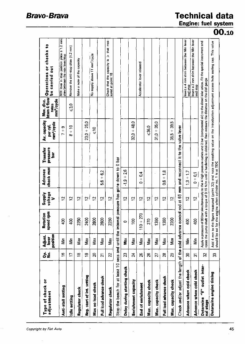
Bravo-Brava Technical data Engine: fuel system
OO.10 O
pera
tions
or
chec
ks t
o be
car
ried
out
MIN
lev
er i
n st
op p
ositi
on p
lace
a 1
.2 m
m
shim
bet
wee
n th
e m
ax le
ver/s
top
Rem
ove
the
anti-
stop
shi
m (
1.2
mm
)
Mak
e a
note
of t
he c
apac
ity
No s
uppl
y ab
ove
11 m
m3/c
ycle
Chec
k th
at t
he c
apac
ity i
s >
that
mea
su
red
at p
oint
18
Stop
the
benc
h fo
r at
leas
t 10
sees
and
unt
il th
e in
tern
al p
ress
ure
has
gone
dow
n to
0 b
ar
Acc
eler
ator
lev
er re
leas
ed
Chec
k an
d/or
adj
ust t
he le
ngth
of t
he c
old
adva
nce
cont
rol r
od a
t 65
mm
and
rec
onne
ct it
to th
e va
lve
lever
In
sert
a 4
mm
shi
m b
etw
een
the
Min
lev
er
and
stop
In
sert
a 2
mm
shi
m b
etw
een
the
Min
leve
r an
d st
op
App
ly a
pre
ssur
e of
80
bar s
imul
tane
ousl
y to
the
4 hi
gh p
ress
ure
outle
ts a
nd 2
bar
(co
mpr
esse
d ai
r) t
o th
e di
esel
inle
t uni
on.
Fit t
he s
peci
al in
stru
men
t and
ro
tate
the
pum
p sh
aft w
ith a
tor
que
of 0
.16
N/m
unt
il a
hard
enin
g is
obt
aine
d, t
hen
mea
sure
the
dis
tanc
e on
the
dia
l gau
ge
Add
4 m
m t
o th
e fig
ure
mea
sure
d (p
oint
32)
and
not
e th
e re
sulti
ng v
alue
on
the
intr
oduc
tion
adju
stm
ent
acce
ss h
ole
seal
ing
cap.
Thi
s va
lue
shou
ld b
e se
t fo
r th
e en
gine
whe
n cy
linde
r no
. 1
is a
t TD
C
Max
. disc
, bt
wn
4 flo
w
rate
s m
m3/c
ycle
o CO V/
Stop
the
benc
h fo
r at
leas
t 10
sees
and
unt
il th
e in
tern
al p
ress
ure
has
gone
dow
n to
0 b
ar
Chec
k an
d/or
adj
ust t
he le
ngth
of t
he c
old
adva
nce
cont
rol r
od a
t 65
mm
and
rec
onne
ct it
to th
e va
lve
lever
App
ly a
pre
ssur
e of
80
bar s
imul
tane
ousl
y to
the
4 hi
gh p
ress
ure
outle
ts a
nd 2
bar
(co
mpr
esse
d ai
r) t
o th
e di
esel
inle
t uni
on.
Fit t
he s
peci
al in
stru
men
t and
ro
tate
the
pum
p sh
aft w
ith a
tor
que
of 0
.16
N/m
unt
il a
hard
enin
g is
obt
aine
d, t
hen
mea
sure
the
dis
tanc
e on
the
dia
l gau
ge
Add
4 m
m t
o th
e fig
ure
mea
sure
d (p
oint
32)
and
not
e th
e re
sulti
ng v
alue
on
the
intr
oduc
tion
adju
stm
ent
acce
ss h
ole
seal
ing
cap.
Thi
s va
lue
shou
ld b
e se
t fo
r th
e en
gine
whe
n cy
linde
r no
. 1
is a
t TD
C
Av. c
apac
ity
per c
yl.
mm
3/cyc
le
CT3 •I-r~
o
•I-oo
23,0
- 2
5,0
O
V/
Stop
the
benc
h fo
r at
leas
t 10
sees
and
unt
il th
e in
tern
al p
ress
ure
has
gone
dow
n to
0 b
ar
32,0
- 4
8,0
o LOCO V/
31,0
-35,
0
35,5
- 3
9,5
Chec
k an
d/or
adj
ust t
he le
ngth
of t
he c
old
adva
nce
cont
rol r
od a
t 65
mm
and
rec
onne
ct it
to th
e va
lve
lever
App
ly a
pre
ssur
e of
80
bar s
imul
tane
ousl
y to
the
4 hi
gh p
ress
ure
outle
ts a
nd 2
bar
(co
mpr
esse
d ai
r) t
o th
e di
esel
inle
t uni
on.
Fit t
he s
peci
al in
stru
men
t and
ro
tate
the
pum
p sh
aft w
ith a
tor
que
of 0
.16
N/m
unt
il a
hard
enin
g is
obt
aine
d, t
hen
mea
sure
the
dis
tanc
e on
the
dia
l gau
ge
Add
4 m
m t
o th
e fig
ure
mea
sure
d (p
oint
32)
and
not
e th
e re
sulti
ng v
alue
on
the
intr
oduc
tion
adju
stm
ent
acce
ss h
ole
seal
ing
cap.
Thi
s va
lue
shou
ld b
e se
t fo
r th
e en
gine
whe
n cy
linde
r no
. 1
is a
t TD
C Tran
sfer
pr
essu
re
bar
Stop
the
benc
h fo
r at
leas
t 10
sees
and
unt
il th
e in
tern
al p
ress
ure
has
gone
dow
n to
0 b
ar
Chec
k an
d/or
adj
ust t
he le
ngth
of t
he c
old
adva
nce
cont
rol r
od a
t 65
mm
and
rec
onne
ct it
to th
e va
lve
lever
App
ly a
pre
ssur
e of
80
bar s
imul
tane
ousl
y to
the
4 hi
gh p
ress
ure
outle
ts a
nd 2
bar
(co
mpr
esse
d ai
r) t
o th
e di
esel
inle
t uni
on.
Fit t
he s
peci
al in
stru
men
t and
ro
tate
the
pum
p sh
aft w
ith a
tor
que
of 0
.16
N/m
unt
il a
hard
enin
g is
obt
aine
d, t
hen
mea
sure
the
dis
tanc
e on
the
dia
l gau
ge
Add
4 m
m t
o th
e fig
ure
mea
sure
d (p
oint
32)
and
not
e th
e re
sulti
ng v
alue
on
the
intr
oduc
tion
adju
stm
ent
acce
ss h
ole
seal
ing
cap.
Thi
s va
lue
shou
ld b
e se
t fo
r th
e en
gine
whe
n cy
linde
r no
. 1
is a
t TD
C
Adva
nce
chec
k m
m
5,6 -
6,2
Stop
the
benc
h fo
r at
leas
t 10
sees
and
unt
il th
e in
tern
al p
ress
ure
has
gone
dow
n to
0 b
ar
CO CN •I-
0 -
0,4
0,6 -
1,8
Chec
k an
d/or
adj
ust t
he le
ngth
of t
he c
old
adva
nce
cont
rol r
od a
t 65
mm
and
rec
onne
ct it
to th
e va
lve
lever
1,3 -
1,7
0 -
0,1
App
ly a
pre
ssur
e of
80
bar s
imul
tane
ousl
y to
the
4 hi
gh p
ress
ure
outle
ts a
nd 2
bar
(co
mpr
esse
d ai
r) t
o th
e di
esel
inle
t uni
on.
Fit t
he s
peci
al in
stru
men
t and
ro
tate
the
pum
p sh
aft w
ith a
tor
que
of 0
.16
N/m
unt
il a
hard
enin
g is
obt
aine
d, t
hen
mea
sure
the
dis
tanc
e on
the
dia
l gau
ge
Add
4 m
m t
o th
e fig
ure
mea
sure
d (p
oint
32)
and
not
e th
e re
sulti
ng v
alue
on
the
intr
oduc
tion
adju
stm
ent
acce
ss h
ole
seal
ing
cap.
Thi
s va
lue
shou
ld b
e se
t fo
r th
e en
gine
whe
n cy
linde
r no
. 1
is a
t TD
C
Supp
ly
volta
ge
V CM CM CM CN CM CN CM
Stop
the
benc
h fo
r at
leas
t 10
sees
and
unt
il th
e in
tern
al p
ress
ure
has
gone
dow
n to
0 b
ar
CM CM CM CM CM CM CM
Chec
k an
d/or
adj
ust t
he le
ngth
of t
he c
old
adva
nce
cont
rol r
od a
t 65
mm
and
rec
onne
ct it
to th
e va
lve
lever
CM CM A
pply
a p
ress
ure
of 8
0 ba
r sim
ulta
neou
sly
to th
e 4
high
pre
ssur
e ou
tlets
and
2 b
ar (
com
pres
sed
air)
to
the
dies
el in
let u
nion
. Fi
t the
spe
cial
inst
rum
ent a
nd
rota
te t
he p
ump
shaf
t with
a t
orqu
e of
0.1
6 N
/m u
ntil
a ha
rden
ing
is o
btai
ned,
the
n m
easu
re t
he d
ista
nce
on t
he d
ial g
auge
Add
4 m
m t
o th
e fig
ure
mea
sure
d (p
oint
32)
and
not
e th
e re
sulti
ng v
alue
on
the
intr
oduc
tion
adju
stm
ent
acce
ss h
ole
seal
ing
cap.
Thi
s va
lue
shou
ld b
e se
t fo
r th
e en
gine
whe
n cy
linde
r no
. 1
is a
t TD
C
Rota
tion
spee
d rp
m
O O O O
2250
2400
2800
2800
2250
Stop
the
benc
h fo
r at
leas
t 10
sees
and
unt
il th
e in
tern
al p
ress
ure
has
gone
dow
n to
0 b
ar
O O O
O r-» CM •I-O
O CM 13
50
1350
2200
Chec
k an
d/or
adj
ust t
he le
ngth
of t
he c
old
adva
nce
cont
rol r
od a
t 65
mm
and
rec
onne
ct it
to th
e va
lve
lever
O O O O
App
ly a
pre
ssur
e of
80
bar s
imul
tane
ousl
y to
the
4 hi
gh p
ress
ure
outle
ts a
nd 2
bar
(co
mpr
esse
d ai
r) t
o th
e di
esel
inle
t uni
on.
Fit t
he s
peci
al in
stru
men
t and
ro
tate
the
pum
p sh
aft w
ith a
tor
que
of 0
.16
N/m
unt
il a
hard
enin
g is
obt
aine
d, t
hen
mea
sure
the
dis
tanc
e on
the
dia
l gau
ge
Add
4 m
m t
o th
e fig
ure
mea
sure
d (p
oint
32)
and
not
e th
e re
sulti
ng v
alue
on
the
intr
oduc
tion
adju
stm
ent
acce
ss h
ole
seal
ing
cap.
Thi
s va
lue
shou
ld b
e se
t fo
r th
e en
gine
whe
n cy
linde
r no
. 1
is a
t TD
C
Adju
st,
lever
po
sitio
n
Min
Min
Max
Max
Max
Max
Max
Stop
the
benc
h fo
r at
leas
t 10
sees
and
unt
il th
e in
tern
al p
ress
ure
has
gone
dow
n to
0 b
ar
Max
Max
Max
Max
Max
Max
Max
Chec
k an
d/or
adj
ust t
he le
ngth
of t
he c
old
adva
nce
cont
rol r
od a
t 65
mm
and
rec
onne
ct it
to th
e va
lve
lever
Min
Min
A
pply
a p
ress
ure
of 8
0 ba
r sim
ulta
neou
sly
to th
e 4
high
pre
ssur
e ou
tlets
and
2 b
ar (
com
pres
sed
air)
to
the
dies
el in
let u
nion
. Fi
t the
spe
cial
inst
rum
ent a
nd
rota
te t
he p
ump
shaf
t with
a t
orqu
e of
0.1
6 N
/m u
ntil
a ha
rden
ing
is o
btai
ned,
the
n m
easu
re t
he d
ista
nce
on t
he d
ial g
auge
Add
4 m
m t
o th
e fig
ure
mea
sure
d (p
oint
32)
and
not
e th
e re
sulti
ng v
alue
on
the
intr
oduc
tion
adju
stm
ent
acce
ss h
ole
seal
ing
cap.
Thi
s va
lue
shou
ld b
e se
t fo
r th
e en
gine
whe
n cy
linde
r no
. 1
is a
t TD
C
a. 6 o z CO oo CJ5 o CM CM CM CM
Stop
the
benc
h fo
r at
leas
t 10
sees
and
unt
il th
e in
tern
al p
ress
ure
has
gone
dow
n to
0 b
ar
CO CM CN LO CN CO CM CM oo CM
oi CM
Chec
k an
d/or
adj
ust t
he le
ngth
of t
he c
old
adva
nce
cont
rol r
od a
t 65
mm
and
rec
onne
ct it
to th
e va
lve
lever
o CO CO CN CO CO CO
Type
of c
heck
or
adju
stm
ent
Ant
i-sta
ll se
tting
Idle
set
ting
Regu
lato
r che
ck
Reg.
sta
rt of
int.
setti
ng
Max
no
load
chec
k
Full
load
adv
ance
che
ck
Regu
lato
r che
ck
Stop
the
benc
h fo
r at
leas
t 10
sees
and
unt
il th
e in
tern
al p
ress
ure
has
gone
dow
n to
0 b
ar
Dela
y du
ring
star
ting
chec
k
Enric
hmen
t cap
acity
End
of e
nric
hmen
t
Max
. cap
acity
che
ck
Max
. cap
acity
che
ck
Full
load
adv
ance
che
ck
Max
. cap
acity
che
ck
Chec
k an
d/or
adj
ust t
he le
ngth
of t
he c
old
adva
nce
cont
rol r
od a
t 65
mm
and
rec
onne
ct it
to th
e va
lve
lever
Adva
nce
whe
n co
ld c
heck
Adva
nce
whe
n co
ld c
heck
De
term
ine
"V"
outle
t in
ter
nal s
tage
De
term
ine
engi
ne ti
min
g
Copyright by Fiat Auto 45

Technical data Bravo-Brava Engine: supercharging OO.io SUPERCHARGING Turbocharger operated by exhaust gases with waste gate valve and air/air heat exchanger (intercooler)
Turbocharger type Garrett
Maximum supercharging pressure N.D.
P4A046A01
CROSS SECTION OF TURBOCHARGER
46 Print no. 506.670
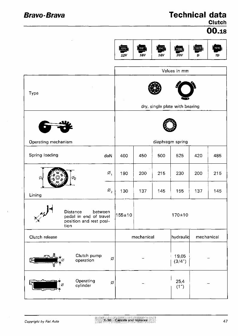
Bravo-Brava Technical data Clutch 00.18
12V 16V 16V 20V D TD
Values in mm
Type
dry, single plate with bearing
Operating mechanism diaphragm spring
Spring loading daN 400 450 500 525 420 485
0, 190 200 215 230 200
0 , Lining
130 137 145 155 137
215
145
Distance between pedal in end of travel position and rest position
155±10 170±10
Clutch release mechanical hydraulic mechanical
Clutch pump 0 operation 0
19,05 (3/4")
Operating 0
0 cylinder 25,4 (1")
Copyright by Fiat Auto X-96 - Cancels and replaces 47

Technical data Gearbox and differential 00-21-27
Bravo-Brava
48 Print no. 506.670/70

Bravo-Brava Technical data Gearbox and differential
00.21-27
DIFFERENTIAL 16V 16V 20V
^ J ^ l Ratio crown fed* wheel & pinion
reduc. 3,886
(15/58) 3,353
(17/57)
3 , 3 5 3 ( 3 , 0 5 3 » ) (17 /57 )
( 1 9 / 5 8 « ) 3,562
(16/57)
15,112 13,107 13,107 (11,934«) 1 2,627
1 * [1
8,343 7,504 7,504 (6,833«) 7,971
5,722 5,096 5,096 (4,640») 5,414
4,334 3,876 3,876
(3,529« 4,118
Ratio at the wheels 3,487 3,256 3,256 (2,964») 3,476
14,760 13,107 13,107
(11,934») 13,924
Differential internal casing bearing conical roller bearings
Adjustment of bearing pre-loading by shims
Thickness of shims
0,05
mm 0,10 2,00 - 3,00
1,70-2,60
Interference to obtain exact bearing pre-loading mm
bearings not pre-loaded = 0,12 bearings pre-loaded (350 daN) = 0,08
m mm <S0,10
Clrnce btwn planet and satellite gears
n A * 0 # >
do not carry out any
adjustment
Adjust, of clrnce btwn planet/satellite gears by shims
do not carry out any ad justment
O * ( f i 0 , 0 5 ) -*\s r\ aoo r\-F chime » ' * *
mm 0,80 - 1,25 Thickness of shims
• French versions
Copyright by Fiat Auto 4 9

Technical data Gearbox and differential 00.21-27
Bravo-Brava
50 Print no. 506.670

Bravo-Brava Technical data Gearbox and differential
00.2127
DIFFERENTIAL
Ratio crown wheel & pinion reduction
16/57 (3,562) ND
n j
Ratio at the wheels
13,923 ND
7,972 ND
5,143 ND
3,665 ND
2,906 ND
13,923 ND
Differential internal casing bearing conical roller bearings
Adjustment of bearing pre-loading by shims
mm o,05 1,70-2,60
Thickness of shims mm o,07 1,70-2,89
n fldgb
T
Interference to obtain exact bearing pre-loading mm
Bearings not pre-loaded = 0,12 bearings pre-loaded (350 daN) = 0,08
I f f
Clearance btwn planet/satellite gears
mm *S 0,10
Adjustment of clrnce btwn planet/sat, gears by shims
no adjustment is carried out
Thickness of shims ^ 0,05^ mm 0,80-1,25
Copyright by Fiat Auto 5 1

Technical data Bravo-Brava Braking system 00.33
FRONT BRAKES
|&( 12V
f iEH| D
iSBl 16V
1^1 TD 75
W>16V 4- (•) 1^1 16V
1^1 TD 100
FRONT BRAKES Values in mm
257
0 11,80 - 12,10 19,80 - 20,10
0 III L/lbCOl 1 11,10 18,55 0 • 1 v - < ^ allowed 10,20 18,20
i|_ s S £ " s < a „ o w e d 1,5
[LSJ^0 Caliper 0 54
^tSm^mmSa^z^. 0 Master cylinder 0 22,225 (7/8")
o = r ^ ^ ^ ^ Brake servo Iso-Vac 8"
pneumatic vacuum servo acting on all four wheels
y J Distance of hydraulic Q=£S=oJ|k piston push rod l_
^ T P " ) from master cylinder — ; ( L support plate
22,45 - 22,65
( • ) W i t h automatic transmission
REAR BRAKES
[®3 180,00-180,25 203,10-203,40
[®3 l | 0 Drum 0<[ > s s n 180,95 204,10
— V ^ > allowed 181,35 204,70
\^Jy S h o e s s < ^ allowed 1,5
^j f^ ie^T" ^ I v y J Wheel cylinders 0 22,00
Load proportioning valve acting on rear wheels
Ratio (reduction) 0,36
5 2 VI'96 - Cancels and updates Print no. 506.670/07

Bravo-Brava Technical data Braking system
00.33
i s 20V
FRONT BRAKES Values in mm
0
Disc
allowed
283,800±284,200
21,900-22,100
20,55
20,20
4^ Brake pads allowed 1,5
(LF# 0 Caliper 0 54
0 Master cylinder (pump) 0 23,81 (15/16")
Servo brake ISO-VAC 8"+7"
pneumatic vacuum servo acting on all four wheels
iJ Distance of hydraulic piston push rod from master cylinder support plate
22,45 - 22,65
REAR BRAKES
-*-s 0 240
] Disc f 10,80 - 11,10
0 i ] Disc 10,10
^<C^ allowed 9,20
II - 1 *
Brake pads s < ^ allowed 1,5
Caliper 0 34
Load proportioning valve acting on rear wheels
Ratio (reduction) 0,36
Copyright by Fiat Auto 53

Technical data Steering 00.41
Bravo-Brava
ENGINE T Y P E
*
12V
|E21| n|S| 16V 161/
ENGINE T Y P E
20V D TD
Type
rack and pinion rack and pinion power assisted
r o © - T - I nn nf turns Innk
3,5 3
/ t o lock
Ratio I Wm
rack travel
142 ±0,8 mm 142 ±1,5 mm
/ + — \
/ \ Turning / \ circle 10,4 m
f ( outer *<^T 1 wheel a 1
•I J 31° ± 30' 31° 30' ± 30'
( i n " e r , a 2
0 4 . . V wheel Steering angle v -37° 20' ± 30' 38° 1 5' ± 30'
^ ^f~ Steering col.
with 2 universal joints
(*) Hydraul ic power steering available on request
5 4 X-96 - Cancels and replaces Print no. 506.670/10

Bravo-Brava Technical data Wheels 00.44
ENGINE TYPE
Whee l r im type
i i | | Tyre inflation NL pressure
S^s >n bar ENGINE TYPE
Whee l r im type Radial, tube less type t y r e Front Rear
ENGINE TYPE
Whee l r im type Radial, tube less type t y r e
average load
heavy load
average load
heavy load
|CS3| 12V 5 % J x U " - 32 5 1 / 2 J x 1 4 " - 37
165 /65 R14 78T ( • ) 175/65 R14 82T
2,2 2,3 2,2 2,5
Brava lev
5 y 2 J x 1 4 " - 37 6J x 14"_ 43
5 1 / 2 J x l 4 " - 37
175/65 R14 82T 185/60 R14 82H 185/60 R14 82H
2,2 2,3 2,2 2,5
Bravo 6J x 14"_ 43 185/60 R14 82H 2,2 2,3 2,2 2,5
Brava 5%J x 14"- 37
6J x 14"_ 43 175/65 R14 82H 185/60 R14 82H
2,2 2,3 2,2 2,5
Bravo 6J x 14"_ 43 6J x 15" - 40 6J x 15" - 40
185/60 R14 82H 185/55 R15 8 1 V ( B ) 195/50 R15 82V ( • )
2,2 2,3 2,2 2,5
i^pi 20v Bravo 6 J x 15" - 49 6 J x 1 5 " - 49
195/55 R15 84V 205/50 ZR15 ( • ) 2,5 2,7 2,2 2,4
5 1 / 2 J x 1 4 " - 37 175/65 R14 82T 2,3 2,3 2,2 2,5
Brava
5%J><14"- 37 5 % J x 1 4 " - 37
6 J x 1 4 " - 4 3
175/65 R14 82T 185/60 R14 82H 185/60 R14 82H 2,3 2,3 2,2 2,5
Bravo 5 1 / 2 Jx14" -37 6 J x 1 4 " - 4 3
175/65 R14 82T 185/60 R14 82H
2,3 2,3 2,2 2,5
SPARE WHEEL (*) 4 B X 1 4 " - 43 4 B x l 5 " - 35
105/70 R14 84M 115/70 R15 90M
4,2
(*) Speed limit: 80 km/h ( • ) Only for versions w i t h mechanical steering ( • ) Not to be used w i th chains because it cou ld interfere w i t h the wheel arch
Copyright by Fiat Auto I I I-96 - Cancels and replaces 55

Technical data Wheels
Bravo-Brava
00.44
W H E E L G E O M E T R Y unladen car ( • )
camber (**)
caster (**)
Front suspension
toe in
front wheel offset A
-7 '± 30' -33'± 30' (only for Bravo 1998)
-9' ± 3 0 ' ( » « )
3°30' ± 30' 2°50' ± 30 ' ( # )
2°18' ± 3 0 ' ( « « )
-1 - 1 mm
camber (**)
in -1° ± 0°30'
0°46' ± 30' (from chassis no. 4.050.320)
Rear suspension
toe in r )
-2,5 - 1,5 mm 0 - 4 (from chassis no. 4.050.320)
rear wheel thrust angle A
(**) A n g l e s canno t be ad justed ( • ) With tyres inflated to the correct pressure and vehicle in running order with 5 litres of fuel
( • ) Angular values which cannot be adjusted, used for the correct alignment of the vehicle ( • ) Versions with power assisted steering and for Bravo 1998 ( • • ) For versions with 1910 TD 75 engine
5 6 X-96 - Cancels and replaces Print no. 506.670/10

Bravo-Brava Technical data Front suspension
00.44 Front suspension independent, Mac Pherson type with steel track control arms anchored to an auxiliary cross member. Offset coil springs and double acting telescopic shock abosrbers. Anti-roll torsion bar.
Coil springs
4Aim /m±\
i j p l i e v ENGINE TYPE ten*. i j p l i e v ENGINE TYPE %jgpfft i2v i j p l i e v j^m-r 20V
Diameter of wire m m 12 ,2±0 ,05 12,5 ± 0,05
(12,7±0,05)* 13,2 ± 0,05
Number of turns 3,75
Direction of coil c lockwise
Height of spring released m m 449,2 ( 461 ) * 461 ( 4 5 4 ) * 404,5 (419,6)*
/ 303 - 335 daN (320,5 - 346,5 d a N ) * m m 192 -
Height of spring under a load of:
/ 340 - 368 daN \ (352 - 382 d a N ) * m m - 192 -I 344 daN V (369 daN) * m m - 192
The springs are subdiv ided into t w o categories, identif iable by a mark
/ 319 daN I (333,5 daN) * height of mm > 1 9 2
yel low (1) for J those under \ a load of: 1
354 daN (367 daN) * height of mm - > 1 9 2 -yel low (1) for J
those under \ a load of: 1
344 daN (369,2 daN) * h e i 9 h t of mm - - > 1 9 2
f 319 daN (333,5 daN) * h e i 9 h t of mm s?192 - -
green (1) for F those under \ a load of: J
354 daN (367 daN) * height o f m m - ^ 1 9 2 -
green (1) for F those under \ a load of: J
344 daN (369 daN) * height of mm - - < 1 9 2
(1) Springs of the same category must be f i t ted. (*) For vehicles w i t h air cond i t ion ing.
( • ) For versions w i t h automat ic transmission, see the th i rd volume.
Shock absorbers Type: telescopic, doub le act ing ( low pressure gas) W A Y - A S S A U T O
Open (start of damping act ion) m m 518 ± 2,5 511 ± 2,5
Closed (metal against metal) m m 361 ± 2,5 3 5 4 ± 2,5
Travel m m 157 157
Stabilizer bar Diameter of stabilizer bar m m 22 23
Copyright by Fiat Auto VI-96 - Cancels and replaces 57

Technical data Front suspension 00.44
Bravo-Brava
Coil springs
Diameter of wire mm 1 2 , 5 ± 0 , 0 5 ( 1 2 , 7 ± 0 , 0 5 ) * 1 2 , 7 ± 0 , 0 5 ( 1 2 , 9 ± 0 , 0 5 ) *
Number of turns 3,75 3,75
Direction of coil clockwise
Height of spring released mm 461 (454)* 454 (449)*
( 340 ± 368 daN Heiaht of spring J (352 ± 382 d a N ) * m m
192 -
under a load of: ) 352 ± 382 daN V. (366 ± 396 d a N ) * m m
- 192
The springs are subdivided into two categories, identifiable by a mark
yellow (1) for f ¥1* height in mm t h c c under ^ ( 1
>192
a load of: ( ( M 7 d a N # h e i ght in mm - >192
green (1) for ( ^ n A n * height in mm thn<*e under •> ( 1
^192 -
a toad of: ( ( | 6 7 d a N _ h e i g h t i n m m - <192
( 1 ) Springs of the same category must be fitted. (*) For vehicles with air conditioning
Shock absorbers Type: telescopic, double act ing ( low pressure gas) W A Y - A S S A U T O
Open (start of damping act ion) mm 518 ± 2,5
Closed (metal against metal) mm 361 ± 2,5
Travel mm 157
Stabilizer bar Diameter of stabilizer bar mm 23
58 VI-96 - Cancels and replaces Print no. 506.670/07
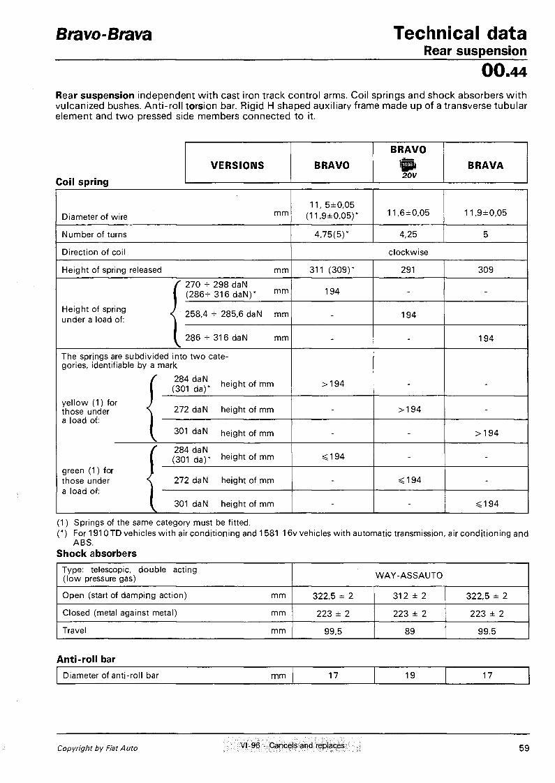
Bravo-Brava Technical data Rear suspension
00.44 Rear suspension independent with cast iron track control arms. Coil springs and shock absorbers with vulcanized bushes. Anti-roll torsion bar. Rigid H shaped auxiliary frame made up of a transverse tubular element and two pressed side members connected to it.
Coil spring
BRAVO
VERSIONS BRAVO tea) BRAVA 2 0 V
Diameter of wire m m
1 1 , 5±0 ,05 (11 ,9±0 ,05 ) * 11 ,6±0 ,05 11 ,9±0 ,05
Number of turns 4 ,75 (5 ) * 4,25 5
Direct ion of coil c lockwise
Height of spring released m m 311 (309 ) * 291 309
/ 270 - 298 daN 1 ( 2 8 6 - 3 1 6 daN) * m m 194 - -
Height of spring J 258,4 + 285,6 daN m m under a load of: \ - 194
I 286 - 316 daN m m - - 194
The springs are subdiv ided into t w o categories, identifiable by a mark
/ 284 daN . . . , . ( (301 da)* h e i g h t o f m m > 1 9 4
ye l l ow (1) for J those under \ 272 daN height of mm - > 1 9 4 -a load ot: 1
( 301 daN height of mm - - > 1 9 4
/ 284 daN ( (301 da ) * n e ' 9 h t o f m m < 1 9 4 - -
green (1) for 1 those under \ 272 daN height of mm
• t i - SS194 -
a load or: 1
1 301 daN height of mm - - «c194
(1) Springs of the same category must be f i t ted. (*) For 1910 TD vehicles w i t h air cond i t ion ing and 1581 16v vehicles w i t h automatic transmission, air cond i t ion ing and
ABS . Shock absorbers
Type: telescopic, double acting ( l ow pressure gas) W A Y - A S S A U T O
Open (start of damping act ion) m m 322,5 ± 2 3 1 2 ± 2 322,5 ± 2
Closed (metal against metal) m m 223 ± 2 223 ± 2 223 ± 2
Travel m m 99,5 89 99,5
Anti-roll bar Diameter of ant i -rol l bar m m 17 19 17
Copyright by Fiat Auto VI -96 - Cancels and replaces 5 9

Technical data Bravo-Brava Electrical equipment 00.55
l^3)l6V 20V
STARTER MOTOR
M. Marelli E80E-12V-0,9KW
(M. Marelli E80E-12V-1 KW)*
M. Marelli M 7 0 R - 1 2 V - 1 , 4 k W
( w i t h reduction gear) Bosch ( • )
0 74 ,5 -1 ,1 /1 ,2
M. Marelli M70R-12V-1,4kW
(with reduction gear)
ALTERNATOR
M. Marell i A 1 1 5 I - 1 4 V - 3 8 / 6 5 A
M. Marell i A 1 1 5 l - 1 4 V - 4 5 / 8 5 A ( » )
M. Marelli A115I-14V-40/75A
M. Marelli A127IR-14V-50/85A(#)
M. Marelli A1271-14V-50/85A
VOLTAGE REGULATOR BUILT IN ELECTRONIC
BATTERY 12V-40Ah-200A 12V-50Ah-250A 12V-60Ah-380A
IGNITION SYSTEM
Bosch SPI Monomotronic
integrated electronic injection/ignition
Weber-Marelli I.A.W. MPI integrated
electronic injection/ignition
HITACHI MPI integrated electronic
injection/ignition system
Bosch MPI Motronic integrated electronic
injection/ignition
IGNITION COIL
Bosch 0.221.503.407
Cooper BAE 920
HITACHI GE 212331
Bosch 0.221.504.006
SPARK PLUGS NGK BKR 6EKC
GOLDEN LODGE 2HLDR CHAMPION RC8BYC
NGK BKR 6EHC CHAMPION RC7BMC
GOLDEN LODGE 2HLDR CHAMPION RC8BYC
CHAMPION RC7BMC
( • ) For vehicles equip ped w i t h air cond i t i cn i r 9 (*) For 1581 16vvers ion w i t h automatic transmission
( • ) From chassis no. 4366551 and n° 6051091
60 XI-97 - Cancels and replaces Print no. 506.670/13

Bravo-Brava Technical data Electrical equipment
00.55
STARTER MOTOR M. Marelli
E 95RL - 12V - 2,2 kW (with reduction gear)
M. Marelli E 95RL - 12V - 2,2 kW (with reduction gear)
Bosch 078,5-2,00/12 ( • • )
ALTERNATOR
M. Marelli
A 1151 - 14V - 38/65A
M. Marelli
A 1151 - 14V - 4 5 / 6 5 A ( » )
M. Marelli
A 1151 - 14V - 40/75A
M. Marelli
A 127IR - 14V - 5 0 / 8 5 A ( » )
VOLTAGE REGULATOR Built in electronic
BATTERY 12V - 60 Ah - 380A
PRE-HEATING ELECTRONIC CONTROL UNIT
SI PEA 2961
BITRON CCD 48C
(Bosch 0.281.003.004) • SI PEA 2904
BITRON CCD 47uP/F2
INJECTION ADVANCE ELECTRONIC CONTROL U N I T ( B )
- LUCAS 41000087 - 101
EGR ELECTRONIC CONTROL UNIT U ) -
MARELLI MCR 108A MARELLI MCR 109A ( • )
HEATER PLUGS
CHAMPION CH 68 BERU 0.100.221.145
BOSCH 0.250.201.005 M. Marelli UX 2A
BERU 0.100.226.249
( • ) For vehicles equipped w i th air condi t ioning ( • ) For vehicles w i t h 1 9 1 0 T D 100 engine ( A ) For vehicles w i t h 1910 TD 75 engine
( • • ) From chassis no. 4364699
Copyright by Fiat Auto XI-97 - Cancels and replaces 61

Technical data Electrical equipment: starting
Bravo-Brava
00.55
STARTER MOTOR 112 V 16V 20V TD
Type M. Marel l i
E80-12V-0,9 kW (E80E-12V-1kW)
M. Marell i M70R-12V-1 ,4 kW
(w i th reduct ion gear)
M. Marel l i E95RL-12V-2,2 kW
Voltage V 12
Nominal power kW 0,9 (1) 1,4 2,2
Rotation, pinion side clockwise
No. of poles 4 4
Field coil series series - parallel
Engagement free wheel
Operation solenoid
End float of armature shaft mm 0,1 - 0,5 (0,15 - 0,45) 0,15 - 0,45
Data for bench test Operating test (*):
current A speed rpm voltage V torque developed daNm
180 (200) 1720 (2200) 9,5 (9 ,8-10) 0,37 (0,38)
360 - 380 1150 8,15 1,30
600 1400 7,9 1,6
Engagement test (*): current A voltage V torque developed daNm
324 (440) 7,1 (7,6)
^0,97 (^1,25)
680 - 700 4,9
3,11
1110 - 1150 4,4 - 4,6
^3 ,9
Free running test (*): current A voltage V speed rpm
40 (44-48) l l ( 4 (11 ,4-M1,5)
8500 - 9000 ' (11400-12300)
60 - 80 4,9
4040
120 - 140 11
4500 - 4750
Relay ( pull in Q.
Windina resistance 1 0,30 - 0,32 (0,32) 0,33 - 0,37 0,23 - 0,27
n \ 1 hold in Q 1,2-1,3 (1,09) 1 , 1 3 - 1 , 2 7 0,93 - 1,07
Lubrication
Internal splines and shaft bushes V S + SAE 10 W
Sleeve and intermediate disc TUTELA MR3
(*) Data obtained at an ambient temperature of 20°C. The data in brackets refers to the starter motor f i t ted on the 1581 version w i t h automatic transmission. N O T E When overhauling it is not necessary to under the insulator between the commutator bars
62 V l " 9 6 • C a n c e l s a n d replaces P r j n t n o 506.670/13

Bravo-Brava Technical data Electrical equipment: recharging
00.55
ALTERNATOR
l^l 12V
tea D ifpi DC)
iSfc 16V
16V
j Pl TD
20V @t 16V (•) ljP»16V(»)
TD (•)
Type M.Marelli
A115I -14V-38/65A M.Marelli
A115I -14V-40/65A M. Marelli
A115I-14V-40/75A M.Marelli
A127IR-14V-50/85A
Nominal voltage V 14
Maximum current A 65 65 75 85
Nominal current at 1800 rpm rpm 38 45 40 50
Nominal current at 6000 rpm A 65 65 75 85
Field winding resistance between the slip rings n
O 2,4 2,587--2,613
Direction of rotation (seen from control side) clockwise
Diode rectifiers bridge
(*) Data obtained at an ambient temperature of 20°C. ( • ) For vehicles equipped w i t h air condi t ion ing
VOLTAGE REGULATOR Built in electronic
Type RTM 151 A RTM 151 B
Alternator speed for test r p m 7000
Thermal stabilization . current -
Test current A -
Regulation voltage (*) V 14,3-14,6
(*) Data obtained at an ambient temperature of 23°C.
Copyright by Fiat Auto VI-96 - Cancels and replaces 63

Technical data Bravo-Brava Electrical equipment: electronic injection/ignition 00.55 INTEGRATED ELECTRONIC INJECTION/IGNITION CONTROL MODULE
Make Bosch 0.261.203.868
Firing order 1 - 3 - 4 - 2
IGNITION COIL WITH 4 HIGH TENSION SOCKETS
Make Bosch
Type 0.221.503.407
Ohmic resistance of primary winding at 20°C Q 0,45 - 0,55
Ohmic resistance of secondary winding at 20°C Q 12000 - 14600
TDC AND RPM SENSOR
Make and type Bosch 0.281.002.102
Sensor winding resistance at 20° C Q 486 - 594
Distance (gap) between the sensor and the crankshaft pulley teeth mm 0,8 + 1,5
ADVANCE ON ENGINE
With engine idling (850 ± 50 rpm) N.D.
SPARK PLUGS
Make and type NGK BKR6EKC Make and type GOLDEN LODGE 2HLDR
Thread M 14x1,25
Electrode gap mm 0,8
64 Print no. 506.670/07

Bravo-Brava Technical data Electrical equipment: injection - electronic ignition
00.55
INTEGRATED ELECTRONIC INJECTION-IGNITION SYSTEM
Type I.A.W. M.P.I WEBER - MARELLI
Firing order 1-3-4-2
INJECTION-IGNITION CONTROL UNIT
Make and type I.A.W. - 1AF.13
COIL WITH 4 HIGH TENSION OUTLETS
Type M. Marelli
Code BAE 920 A
Resistance of primary winding at 20°C Q 0.580
Resistance of secondary winding at 20°C Q 9100
SPARK PLUGS
Make and type NGK BKR6EKC GOLDEN LODGE 2 H L D R
Thread M 1 4 x 1 . 2 5
Electrode gap mm 0.8
TOP DEAD CENTRE AND RPM SENSOR
Type JAEGER
Code CVM 01
Sensor winding resistance Q 575 - 750
Gap between sensor and crankshaft pulley teeth _ r mm 0.5-1.5
ADVANCE ON ENGINE
With engine idling 800 ± 30 rpm 10°
Copyright Fiat Auto 65

Technical data Bravo-Brava Electrical equipment; electronic injection-ignition 00.55
INTEGRATED ELECTRONIC INJECTION-IGNITION SYSTEM
Type HITACHI MFI-0
Firing order 1 - 3 - 4 - 2
IGNITION COIL (1 FOR SPARK PLUG)
Type HITACHI
Code GE 212331
Ohmic resistance of primary winding at 20°C Q 0.495 - 0.605
Ohmic resistance of secondary winding at 20°C Q -
RPM AND TOP DEAD CENTRE SENSOR
Make and type HITACHI GE 1 0 8 1 0 1
Sensor winding resistance 0. 5 1 3 - 627
Distance (gap) between sensor and crankshaft pulley tooth mm 0 . 4 - 1 . 2
KNOCK SENSOR
Make and type NGK KUE-03
TIMING AND CYLINDER RECOGNITION SENSOR
Make and type Bosch B 232.070.023
ADVANCE ON ENGINE
With engine idling (850±50/min) 1 0 ° ± 5°
SPARK PLUGS
Make and type NGK BKR6EKC
Champion RC7BMC Golden Lodge 2HLDR
Thread M 1 4 x 1 . 2 5
Electrode gap mm 0.8
66 X-95 Supersedes previous version Publication no. 506.670/04

Bravo-Brava Technical data Electrical equipment: electronic injection/ignition
00.55
INTEGRATED ELECTRONIC INJECTION/IGNITION SYSTEM
Make Bosch 0.261.203.994
Firing order 1 - 2 - 4 - 5 - 3
IGNITION COIL (1 PER SPARK PLUG)
Make Bosch
Type 0.221.504.006
Ohmic resistance of primary winding at 20°C Q 0,4
Ohmic resistance of secondary winding at 20°C Q 8500
TDC AND RPM SENSOR
Make and type Bosch 0 . 2 8 1 . 0 0 2 . 1 0 2
Sensor winding resistance at 2 0 °C Q 774 - 946
Distance (gap) between the sensor and the crankshaft pulley teeth m m 0 , 8 + 1,5
DETONATION SENSOR
Make Bosch
Type 0.261.231.095
SPARK PLUGS
Make and type CHAMPION RC7BMC
Thread M 1 4 x 1 , 2 5
Electrode gap mm 0,8
Copyright by Fiat Auto X-95 - Cancels and replaces 67

Technical data Bravo-Brava Special tools 00.A
Tool number D E S C R I P T I O N O F T O O L
E N G I N E T Y P E
Tool number D E S C R I P T I O N O F T O O L
01 12V
0 16V
01 16V 20V
0 i D
0 TD
ENGINE
1850132000 Spanner (13 mm), with 112" socket, for removing inlet manifold fixings
m
1850167000 Spanner (13 mm) for fuel injection pump securing screws • 1850184000 Spanner for removing and refitting spark plugs • • • • 1852128000 Tool for removing and refitting injectors • • 1852138000 Spanner for adjusting injector pipe pressure connectors • • 1852147000 Spanner for removing cylinder head • 1852154000 Spanner, 1 /2" socket, for cylinder head fixing bolts • • • • 1852157000 Spanner, 1 /2 " socket, for cylinder head fixing bolts • 1852159000 Spanner for removing-refitting belt tensioner • 1852161000 Spanner for phase transformer • 1852162000 Spanner for alternator pulley • 1860054000 Drift ( 0 22 mm) for removing and refitting connecting rod
pin bush • 1860183000 Pliers ( 0 7 5 - 1 1 0 mm) for removing and refitting piston cir-
clips
1860251000 Drift for removing gudgeon pin from piston • 1860303000
Tool for fitting gudgeon pin circlips on piston • 1860313000
Drift for fitting oil seal on valve guide
1860395000 Drift for removing valve guide
1860443000 Pressure lever for inserting tool for retaining tappets whilst adjusting valve clearance • •
68 VI-96 - Cancels and replaces Print no. 506.670/07

Bravo-Brava Technical data Special tools
00.A
ENGINE TYPE
Tool number DESCRIPTION OF TOOL
t in
12V 16V 16V 20V D TD
1860443000 Tool for tensioning t iming belt • 1860454000 Drift for f i t t ing oil seal on valve guide • • 1860460000 Drift for f i t t ing valve guides • 1860470000 Tool for support ing cylinder head wh i ls t overhaul ing
1860486000 Drift for f i t t ing valve guides • 1860490000 Tool for retaining valve leakage test equipment 1895868000
(to be used w i th 1860470000) • 1860644000 Tool , valve removal and refitt ing (to be used w i t h
1860877000 and 1860804000) •
1860644000 Tool for removing and ref i t t ing valves (to be used w i t h 1860322000) •
1860644000 Tool for removing and refit t ing valves (to be used w i t h 1860749000) •
1860647000 Flywheel lock (at the bench) • 1860650000 Drift ( 0 25 mm) for removing and ref i t t ing small end bush • 1860662000 Tool for removing cartr idge oil filter or fuel fi lter • 1860666000 Tool for retaining camshaft whi ls t removing and ref i t t ing side
supports • 1860700000 Band ( 0 60 -125 mm) for in t roducing normal and oversize
pistons in cylinders
1860724000 Tool for retaining tappets whi ls t replacing shims • • 1860745100
Tool for tensioning toothed belts ( to be used w i t h specific too ls) •
1860745200 Tool for t iming system toothed belt tensioning ( to be used w i t h 1860745100) •
Copyright by Fiat Auto Vl-96 - Cancels and replaces 69

Technical data Bravo-Brava Special tools 00.A
ENGINE TYPE
Tool number DESCRIPTION OF TOOL
1 0 12V 16V
0 16V
0 20V D
0 TD
1860749000 Support for cyl inder head wh i l s t removing and ref i t t ing valves • 1860757000 Tool for removing cartridge oi l f i l ter • 1860758000 Tool for removing cartridge oi l f i l ter • • • 1860765000
Tool for retaining toothed pul l ies and inject ion pump drive pulley • •
1860766000 Flywheel lock • 1860771000 Flywheel lock • 1860790000 Lever for removing and ref i t t ing valves (to be used w i t h
1860786000 -1860787000 -1860788000 -1860789000 ) • •
1860810000 Dummy spark p lug for ante-chamber (to be used when refitt ing ante-chamber f ix ing bush) •
1860812000 Tool for ref i t t ing valve guides • • • • 1860813000 Guide for f i t t ing oi l seal on valve guides • • • • 1860814000 Drift for f i t t ing oi l seal on valve guides • 1860815000 Adaptor for rotat ing crankshaft
1860816000 Drift for f i t t ing oi l pump gasket • • • • • 1860817000 Tool for centering crankshaft cover gasket • • • • 1860818000 Tools for camshaft t iming • 1860821000 Tool for removing small end bush • • • • 1860822000 Tool for t iming oi l pump •
70 VI-96 - Cancels and replaces Print no. 506.670/07

Bravo-Brava Technical data Special tools
00.A
ENGINE TYPE
Tool number DESCRIPTION OF TOOL
l l 12V 16V
l 9t 16V
tap 20V D TD
1860824000 Tool for introducing camshaft gasket • • 1860831000 Spanner for rotating t iming pullies • • 1860833000 Spanner for removing-ref i t t ing oil sump • • 1860834000 Spanner for removing-ref i t t ing oil sump • • 1860835000 Tool for extracting oil seal on valve gu ide • • • • • 1860836000 Tool for locking rotat ion of crankshaft • • 1860844000 Tool for f i t t ing gasket for camshaft, inlet side • 1860845000 Spanner for tensioning t im ing belt • 1860846000 Flywheel lock (operations at the bench) • • • • 1860848000 Spanner for camshaft pul ley, exhaust side • 1860856000 Spanner for t iming pulley, inlet side • 1860859000 Supports for removing-ref i t t ing power uni t ( to be used w i t h
1860860000) • • •
1860859001 Connect ing bracket for removing-ref i t t ing power uni t (to be used w i t h 1860859000 and 1860860000) •
1860859002 Adaptor for removing-ref i t t ing power unit ( to be used w i t h 1860859000 and 1860860000)
• 1860859003 Adapto r for removing-ref i t t ing power unit ( to be used w i t h
1860859000 ) •
1860860000 Suppor t for removing-ref i t t ing power uni t
1860874000 Tools for camshaft t im ing •
Copyright by Fiat Auto VI-96 - Cancels and replaces 71

Technical data Special tools
Bravo-Brava
00.A
Tool n u m b e r DESCRIPTION OF TOOL
ENGINE TYPE
Tool n u m b e r DESCRIPTION OF TOOL
I0I 12V 16V
0 16V
0 20V
lfEX3| 0
0 TD
1860875000 Tools for camshaft t iming • 1860876000 Tool for tens ioning t iming belt • 1860877000 Tool for removing valves • 1860878000 Tool for f i t t ing crankshaft f ron t cover gasket • 1860879000 Grip for tool for f i t t ing crankshaft rear cover gasket • • 1860880000 Tool for f i t t ing crankshaft rear cover gasket ( to be used w i t h
1860879000) • 1860881000 Tool for f i t t ing crankshaft rear cover gasket ( to be used w i t h
1860879000) • 1860882000 Tool for f i t t ing camshaft cover gasket and auxil iary shaft cov
er • 1860883000 Pin for centering ante-chamber • 1860884000 Spanner for removing-ref i t t ing combust ion ante-chamber • • 1860885000 Spanner for rotat ing camshaft pullies (to be used w i t h
1860831001) • 1860886000 Tool for extract ing inject ion p u m p pulley • 1860887000 Tool for pos i t ion ing rpm sensor • 1860892000 Tool for t im ing camshafts • 1860893000 Spanner for fuel pump cover • • • • 1860895000 Vertical support for dial gauge for detecting T.D.C. • 1860896000 Graduated disc for engine t i m i n g • 1860898000 Flywheel lock (on vehicle) • •
72 VI-96 - Cancels and replaces Print no. 506.670/07

Bravo-Brava Technical data Special tools
00.A
ENGINE TYPE
Tool number DESCRIPTION OF TOOL
01 12V
01 16V
0| 16V
lujjjljl| 20V D TD
1860899000 Tool for t im ing camshaft • 1860901000 Tool for posi t ioning T.D.C. • 1860905000 Tool for posi t ioning T.D.C. • 1861001011 Pair of brackets for f ix ing engine to rotat ing stand • 1861001039 Pair of brackets for f ix ing engine to rotat ing stand • • 1861001041 Pair of brackets for f ix ing engine to rotat ing stand • 1861001042 Pair of brackets for f ix ing engine to rotat ing stand • 1865091000 Tool for checking injection pump advance • 1867019000 Drift for removing and refitt ing bush in crankcase for oil pump
drive gear •
1867029000 Flywheel lock • 1867030000 Flywheel lock (on vehicle) • 1870404000 Suppor t for dial gauge for measuring cylinder liner recesses or
project ions • • 1890385000 Reamer for valve guide openings • • • • 1895762000 Dynamometer for checking auxil iary shaft drive belt tension • • • • • • 1895868000 Valve leakage test equipment • • • • • • 1895890000 Fuel pump delivery pressure gauge w i t h unions • • • • 1895897000 Graduated disc for angular t ighten ing of cylinder head f ix ing
nuts • • • • • •
Copyright by Fiat Auto VI-96 - Cancels and replaces 73

Technical data Bravo-Brava Special tools 00.A
ENGINE TYPE
Tool number DESCRIPTION OF TOOL
10 12V
101 16V
0 16V
tea) 20V D
01 TD
1895942000 Graduated disc for angular t ightening of cyl inder head f ix ing nuts •
1896245000 Gauge to check valve stem height after valve seat gr inding • CLUTCH
1870081000 Guide pin for centering c lu tch disc • 1870447000 Guide pin for centering c lu tch disc • 1875086000 Guide pin for centering c lu tch disc • • •
GEARBOX-DIFFERENTIAL
1842133000 Tool for removing differential bearing and gearbox gear •
1842134000 Tool for removing gearbox gears and hubs • 1845028000 Reaction too l for removing differential bearings • 1845057000 Tool for removing bush for lay shaft 5'h speed gear • 1845062000 Tool for removing constant veloci ty jo in t f rom front wheel
drive shaft ( to be used w i t h 1847017001) • • • • 1847017001 Mass (to be used w i t h 1860889000)
1847017004 Plate for extract ing f langed shaft f rom planet gear (to be used wi th 1847017001) • • • •
1847056000 Tool for extract ing differential output shafts • 1850132000 Spanner for bolts f ix ing dif ferential casing cover • 1850113000 Spanner (12 mm) for gearbox oil drain p lug
(*) Tools for Aisin automatic gearbox
74 VI-96 - Cancels and replaces Print no. 506.670/07

Bravo-Brava Technical data Special tools
00.A
ENGINE TYPE
Tool number DESCRIPTION OF TOOL
0 12V 16V
01 16V 20V D
0 TD
1855035000 Spanner (19 mm) for removing and refit t ing gearbox
1860691000 Drift for removing and refitt ing gear hardening ball plug •
1860851000 Cross member for removing-ref i t t ing gearbox
1860851001 Transverse adaptor for removing-ref i t t ing gearbox (to be used w i th 1860851000)
1860870000 Connector for checking line pressure • (*)
1860873000 Bracket for removing-ref i t t ing gearbox • •
• (*) • •
1860889000 T w o - w a y connector for mass ( to be used w i t h 1847017001) • •
• o • • • •
1870007000 Universal handle
1870152000 Drift for f i t t ing hubs and gears on main and lay shafts • •
1870419000 Tool for f i t t ing main shaft gasket on bell housing (to be used w i t h 1870007000)
1870448000 Tool for f i t t ing front bearing inner race • • • •
1870469000 Tool for f i t t ing differential bearing ( to be used w i t h 1870007000)
•
1870478000 Tool for f i t t ing 4'h speed gear bush and rear bearing • • • •
1870629000 Drift for f i t t ing differential casing cover gasket ( to be used w i t h 1870007000)
• •
• (*)
1870630000 Drift for f i t t ing differential casing gasket ( to be used w i t h 1870007000)
•
1870631000 Drift for f i t t ing main and lay shaft bearings and gears •
1870632000 Drift for f i t t ing bearings •
(*) Tools for Aisin automatic gearbox
Copyright by Fiat Auto VI-96 - Cancels and replaces 75

Technical data Bravo-Brava Special tools 00.A
ENGINE TYPE
Tool number DESCRIPTION OF TOOL
12V 16V 01 16V 20V
| E E S |
D 01
TD
1870633000 Drift for f i t t ing c lu tch release shaft bush • 1871001014 Suppor t for gearbox-dif ferential unit wh i ls t overhaul ing (to
be f i t ted to 1861000000 or 1871000000) • 1874140005 Pair of tools for staking gearbox shaft nuts (to be used w i t h
1874140001) • 1874541000 Tool for f i t t ing differential bearing outer race • 1875016000 Drift to f i t gasket on axle shaft f lange • • • • 1875017000 Tool to remove and refit differential bearing rings (to be used
w i t h 1840005003) • • • • 1875088000
Drift for f i t t ing main and lay shaft bearings • 1881124000
Pliers for adjust ing main and lay shaft rear bearing circl ips • 1895411000 Pipe and 1 / 4 " connectors for checking automatic gearbox oil
pressure
1895424000 Pressure gauge ( 0 - 2 5 bar) for checking automatic gearbox oil pressure
• n
1895655000 Tool to select differential bearing adjust ing shims (to be used w i th 1895884000)
• BRAKES
1856132000 Spanner (10-11 mm) for adjust ing brake f lu id pipe un ions
1856133000 Spanner for adjust ing rear brake caliper self-adjust ing device • 1872273000 Set of too ls to hold cyl inder pistons w h e n install ing brake
shoes • • • • • 1895899000
Vacuum gauge w i t h connectors for checking operat ion on vehicle of vacuum pump \
• 1895901000 Tool for adjust ing posi t ion of load propor t ion ing valve • • • • •
(*) Tools for Aisin automatic gearbox
76 VI-96 - Cancels and replaces Print no. 506.670/07

Bravo-Brava Technical data Special tools
00.A
Tool n u m b e r DESCRIPTION OF TOOL
ENGINE TYPE
Tool n u m b e r DESCRIPTION OF TOOL
12V 16V 16V 20V D TD
STEERING
1847035000 Puller for steering rod ball pins
1860888000 Tool for removing-ref i t t ing bearing for power steering pump support
• SUSPENSION
1845028000 Tool for removing front hub bearing inner race f rom f lange (to be used w i t h 1840005003, 1840005302 and 1840005400)
1847014000 Percussion extractor for whee l hub caps
1874551000 Tool for retaining front shock absorber stem whi ls t adjust ing f ix ing nut
1874555000 Pneumatic too l for compressing suspension springs when remov ing shock absorber
1875055000 Drift to f i t f ront wheel hub bearings ( to be used w i t h 1870007000)
1875059000 Drift for f i t t ing rear wheel hub caps
ELECTRICAL EQUIPMENT
1860893000 Tool for removing fuel gauge ring nut • • • • 1860897000 Tool for extract ing radio
BODYWORK
1860890000 Spanner for removing-ref i t t ing door hinges
1878034000 Tool for removing w i n d o w opening handles
1878077000 Tool for removing door panel or f ix ing but tons
1878080000 Tool for pos i t ion ing door check strap wh i ls t refi t t ing f lexible retaining p in ( to be used w i t h 1878081000)
1878081000 Pliers for removing-ref i t t ing door check strap flexible retaining pin ( to be used w i t h 1878080000 wh i l s t refi t t ing)
Copyright by Fiat Auto VI-96 - Cancels and replaces 77

Technical data Special tools
Bravo-Brava
00.A
Tool number DESCRIPTION OF TOOL
ENGINE TYPE Tool
number DESCRIPTION OF TOOL Iffli 12V 16V
0 ) 16V
lga> 20V
| Q I S |
D TD
ORDINARY TOOLS
1840005000 Universal extractor
1840206000 Percussion extractor ( to be used w i t h specific too ls)
1846017000 Base for puller hal f - r ings
1847017001 Percussion extractor ( to be used w i t h specific too ls)
1861000000 Rotat ing stand for overhaul ing engine (also used for gearboxes and differentials)
1861000001 Pair of sections for brackets suppor t ing the engine on rotat ing stand 1861000000
1870007000 Universal handle
1870404000 Support for measuring recesses and projections ( to be used w i t h 1895881000)
1871000000 Rotat ing co lumn for overhaul ing gearboxes and differentials
1876048000 Extractor for M I N I HYLOK CONTACT (MHF) 0 2,15 mm type terminals
1881138000 Adjustable plires for pipe restricting bands and tabs
1882002010 Tool panel to be f ixed to wal l or s tand 1882003000 (wi th hooks)
1882003000 Stand t o hold t w o too l panels
1882011000 Set of addit ional hooks (50) for t oo l panel
1895113000 Dial gauge (0,05-0,10. . .0,80 mm) for checing various clearances
1895881000 Dial gauge to be used w i t h specific too ls (measuring capacity mm 10; shank length m m 16,7)
1895882000 Dial gauge to be used w i t h specif ic too ls (measuring capacity mm 10; shank length m m 88)
1895884000 Dial gauge to be used w i t h specific too ls (measuring capacity mm 5; shank length m m 16,5)
78 VI-96 - Cancels and replaces Print no. 506.670/07

Bravo-Brava Technical data Tightening torques
oo.
DESCRIPTION Thread size
Tightening torques
daNm
ENGINE TYPE
DESCRIPTION Thread size
Tightening torques
daNm 0 12V 16V
0 16V 20V D
0 TD
ENGINE
Main bearing caps f ix ing , f langed blot
M 1 0 8 • Main bearing caps f ix ing , f langed blot M12 2 + 1 0 0 ° • • • • • Main bearing caps f ix ing , f langed blot
M 1 2 x 1 , 2 5 2 , 5 + 1 0 0 ° • (Dust) shield f ix ing, bo l t M 6 0,9 • • • • Sump oil drain piug
M14 2,5 • Sump oil drain piug M18 2 • • • Sump oil drain piug
M22 5 • Oil sump f ix ing, bolt
M6 0,9 • • • • • Oil sump f ix ing, bolt
M8 2,5 • • • • Flywheel side and t iming side cover f i x ing , bolt M6
0,7 • Flywheel side and t iming side cover f i x ing , bolt M6 0,9 • • • •
Timing belt shields f ix ing , bol t M6 0,9 • • • • •
Timing belt shields f ix ing , bol t M8 2,5 • Timing belt shields f ix ing , bol t M 1 0 * 1 , 2 5 5 •
Cylinder head to crankcase f ix ing, bolt M1 Ox 1,25 4 +
9 0 ° + 9 0 ° • •
Cylinder head to crankcase f ix ing, bolt M10 4+
90°+90°+90° • •
Cylinder head to crankcase f ix ing, bolt M10 5+
90°+90°+90° •
Cylinder head to crankcase f ix ing , bolt M10 6,5 +
90°+90°+90° •
Engine support to crankcase f ix ing, bolt M10 5 •
Engine support to crankcase f ix ing, bolt M 1 0 x 1 , 2 5 7 • • • Engine support to crankcase f ix ing, bolt M8 2,5 •
Camshaft cap f ix ing, bo l t and nut M8 1,9 • Camshaft cap f ix ing, bo l t and nut M7 1,5 • • • •
Tappet cover to cyl inder head f ix ing, bol t M 6 0,9 • • • • Inlet manifold to cyl inder head f ix ing, nut M8
2,5 • • • • Inlet manifold to cyl inder head f ix ing, nut M8 3 •
Exhaust manifold to cyl inder head f ix ing, nut M8 2,5 • • • • • Exhaust manifold to cyl inder head f ix ing, nut M8
3 • Flywheel to crankshaft f i x ing , bol t M6 0,9 • • • Bearing caps f ix ing, bol t
M8 2+40° • Bearing caps f ix ing, bol t M8 2 + 6 0 ° • • Bearing caps f ix ing, bol t
M10 2,5 + 50° • Bearing caps f ix ing, bol t
M9*1 2,5 + 60° • Copyright by Fiat Auto XI-97 - Cancels and replaces 79

Technical data Tightening torques
Bravo-Brava
00.
DESCRIPTION
Tightening torques
Thread size
daNm
ENGINE TYPE
12V 01
16V 16V 20V IcSi I0i
D ! TD
Engine f lywheel f ix ing, bolt M10 8,3 •
Engine f lywheel f ix ing, bolt M12*1 ,25 16 • • • • Engine f lywheel f ix ing, bolt M 1 2 * 1 , 2 5 14,2 •
Crankshaft gear f i x ing , bolt (*) M16 left
36 • • • • Auxi l iary pulley t o crankshaft gear f ix ing, bolt M8
2,5 • • Auxi l iary pulley t o crankshaft gear f ix ing, bolt M8 3,2 •
Gear to camshaft f i x ing , bolt ( in let and/or exhaust) M12 12
Butterf ly casing to inlet manifold f i x ing , bolt M6 0,9 • Accelerator bracket to inlet mani fo ld f ix ing, bo l t
M6 0,9 • Sensors to cylinder block/crankcase and cylinder head f ix ing, bolt M6 0,9 • • • • Detonat ion sensor to cylinder block/crankcase f ix ing, bol t M8 2,5 • • • Coils support to cyl inder head f i x ing , bolt M6 0,9 • Connector mount ing bracket to inlet mani fo ld and coi ls support f i x ing , bolt M6 0,9 • Oil pump to crankcase f ix ing, bo l t
M6 0,9 • • • • Oil pump to crankcase f ix ing, bo l t
M8 2,5 • Oil d ipst ick f ix ing, bolt and nut M6 0,9 • • • Water pump f ix ing, bol t PV18 2,5
Water inlet pipe to cyl inder head f ix ing, bolt M6 0,9 • • •
Water inlet pipe to cyl inder head f ix ing, bolt M8 2,5 • • Water inlet pipe to cyl inder head f ix ing, bolt
M10 5 • Thermostat to cylinder head f i x ing , bolt M8 2,5
Air condi t ion ing compressor suppor t to crankcase f ix ing, bo l t M1 Ox 1,25 5 • • Alternator mount ing to crankcase f ix ing, bol t
M8 2,5 • Alternator mount ing to crankcase f ix ing, bol t M10><1,25 7 • Alternator mount ing to crankcase f ix ing, bol t
M 1 0 * 1 , 2 5 5 • (*) The bolt should not be lubricated
80 XI I -95 - Update
Print no. 506.670/13

Bravo-Brava Technical data Tightening torques
oo.
DESCRIPTION Thread size
Tightening torques
daNm
ENGINE
DESCRIPTION Thread size
Tightening torques
daNm 12V 01 16V
0 ) 16V *2W
0 TD
Cover and bracket to water pump casing f i x ing , bolt
M8 2,3
Water pump to cylinder head f ix ing, nut w i t h f lange
M 8 2 • • • • Oil pump drive shaft dr iven gear f ix ing, bol t M1 Ox 1,25 8 • Thermostat t o cylinder head f ix ing, nut M8 2
Driven gear to oi l pump drive gear f i x i ng , bol t M 1 0 x 1 , 2 5
left 7 •
Butterfly casing to inlet mani fo ld fixinjg, bo l t M 8 2,5 • •
Ante-chamber f ix ing, r ing nut M 3 2 x l , 5 11,8 • • Injection pump f ix ing, nut for stud M8 2,5 • Injection pump f ix ing, bo l t M 8 2,5 • • Flexible mount ing to water pump casing f i x ing , nut
M12x-|,25 8 • Injection pump drive gear f i x ing , nut M12x-|,25 4,9 • Injection pump drive gear f i x ing , nut
M 1 4 X 1 , 5 5 • Reaction bracket to oil f i l ter support and in ject ion pump f i x ing , bolt
M 8 2,9 • Injection pump mount incpto crankcase and inlet manifold f ix ing, bolt " *
M 8 2,5 • Oil fi l ter and injection p u m p mount ing f i x ing , u p per bolt or nut
M 1 2 x l , 2 5 9,8 • Oil fi lter and inject ion p u m p mount ing f i x ing , lower bolt
M 1 0 x l , 2 5 7,1 • Complete injector M 2 4 x 2 5,5 • • Heater plugs M 1 2 x 1 , 2 5 1,5 • Fuel supply pipe on in ject ion pump and on injector, nuts
M 1 2 X 1 , 2 5 2,9 •
Copyright by Fiat Auto 81

Technical data Bravo-Brava Tightening torques oo.
Tightening torques
ENGINE
DESCRIPTION Thread size
Tightening torques
daNm 1 0 12V
0 16V
0 16V
0 20V D
0 TD
Union on inject ion pump M 1 2 X 1 , 5 3,2 • Oil f i l ter mount ing union M 2 0 X 1 , 5 5 • Alternator to bracket f ix ing, bo l t M 1 0 x 1 , 2 5 4,3 • Alternator to mount ing f ix ing, bo l t
M 1 2 x 1 , 2 5 8,5 • Alternator to mount ing f ix ing, bo l t
M 1 0 x 1 , 2 5 5 • Alternator to mount ing f ix ing, nut M 1 2 X 1 , 2 5 6 • Alternator mount ing to crankcase f ix ing, bol t M 1 0 x 1 , 2 5 5 • • • • Alternator mount ing f ix ing, nut M 1 0 X 1 , 2 5 4,3 • Alternator to mount ing f ix ing, nut M 1 2 x 1 , 2 5 7 • • • Turbocharger to exhaust un ion f i x ing , nut M8 2,5 • Bolt for bracket strengthening exhaust mani fo ld complete w i t h turbocharger to crankcase
M 1 0 X 1 , 2 5 4 • Turbocharger to exhaust mani fo ld f ix ing, nut M8 2,5 • Power steering pump to support f i x ing , bol t M8 2,5 • • • • Pulley to power steering pump f i x ing , bol t M8 2,5 • • • Power steering pump to suppor t f i x ing , nut M 1 0 x 1 , 2 5 4,8 • Power steering pump after tens ion ing belt f i x ing , bol t
M 1 0 x 1 , 2 5 4,8 • Air condit ioner to support f i x ing , bol t w i t h f lange M 1 0 x 1 , 5 5 • • • • Reaction bracket to support f i x ing , bol t w i t h f lange
M 1 0 x 1 , 5 5 • • • •
82 Print no. 506.670
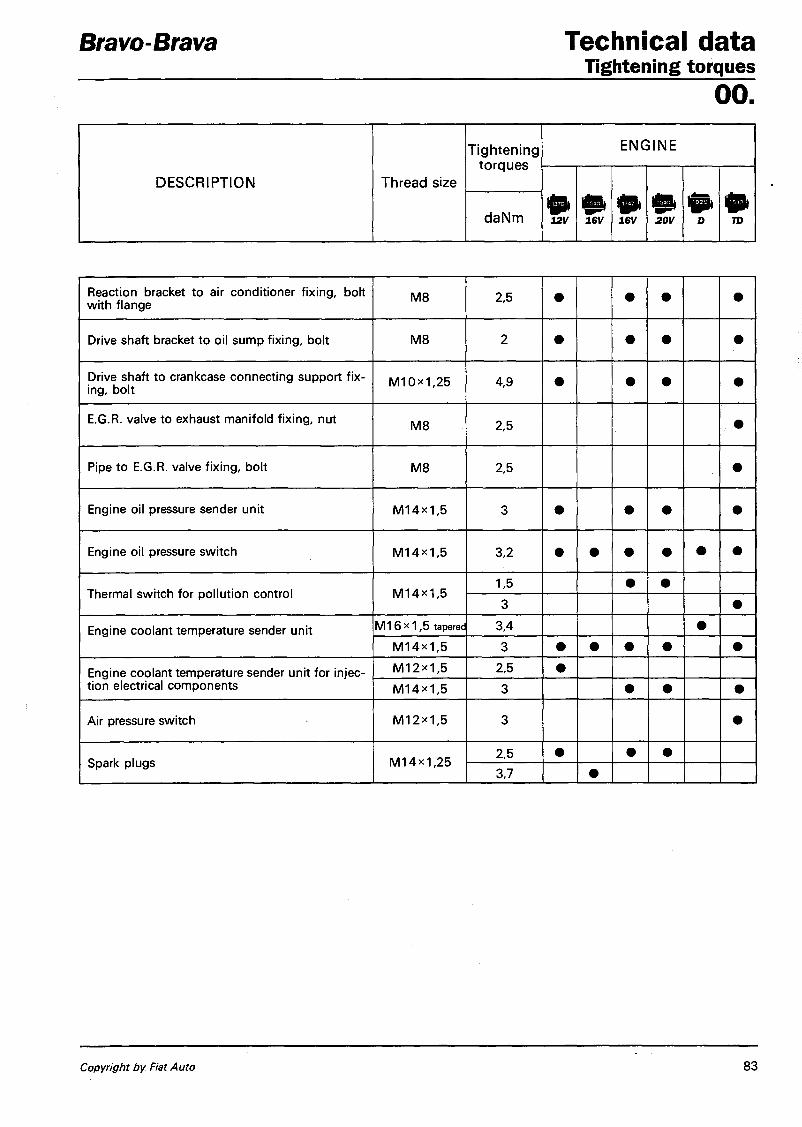
Bravo-Brava Technical data Tightening torques
oo. Tightening
torques ENGINE
DESCRIPTION Thread size
Tightening torques
daNm 12V 0 16V
01 16V
0 20V
tea D 0
TD
Reaction bracket to air condit ioner f i x ing , bolt w i t h f lange
M8 2,5 • • • • Drive shaft bracket to oi l sump f ix ing, bol t M8 2 • • • • Drive shaft to crankcase connect ing support f ix ing, bo l t M 1 0 X 1 , 2 5 4,9 • • • • E.G.R. valve to exhaust mani fo ld f i x ing , nut
M8 2,5 • Pipe to E.G.R. valve f ix ing , bol t M8 2,5 • Engine oil pressure sender uni t M 1 4 X 1 , 5 3 • • • • Engine oil pressure sw i tch M 1 4 X 1 , 5 3,2
Thermal swi tch for po l lu t ion control M 1 4 x l , 5 1,5 • •
Thermal swi tch for po l lu t ion control M 1 4 x l , 5 3 •
Engine coolant temperature sender uni t M 1 6 x 1 , 5 tapered 3,4 • Engine coolant temperature sender uni t M 1 4 x 1 , 5 3 • • • • •
Engine coolant temperature sender uni t for inject ion electrical components
M 1 2 x 1 , 5 2,5 • Engine coolant temperature sender uni t for inject ion electrical components M 1 4 x 1 , 5 3 • • • Air pressure swi tch M 1 2 x 1 , 5 3 • Spark plugs M 1 4 x 1 , 2 5
2,5 • • • Spark plugs M 1 4 x 1 , 2 5
3,7 •
Copyright by Fiat Auto 83

Technical data Bravo-Brava Tightening torques oo.
DESCRIPTION Thread size Tightening torquesio
daNm
ENGINE EXHAUST Front section of exhaust pipe with differential side bracket fixing, bolt M8 1,8
POWER UNIT MOUNTING
Bracket, differential side, to gearbox fixing, bolt (1370) M12x1,25 9
Bracket, differential side and engine side, to gearbox, fixing bolt (1370) M10><1,25 4,5
Mounting, engine side, to engine support, fixing nut (1998) M12x1,25 8
Support, differential side, to gearbox, fixing, bolt M12x1,25 8,5
Engine to bodyshell fixing, bolt with flange M8 3,2
Differential support to gearbox fixing, nut M12x1,25 8
Bracket, differential side, to gearbox fixing, bolt (1929 D-1910 TD) M10x1,25 5
Support to gearbox fixing, bolt with flange (1370) M10x1,25 5
Connecting rod support to bodyshell fixing, bolt with flat tapered washer (1747-1998) M8
3,8 2,8
Reaction rod to bracket and engine support fixing, bolt (1747-1998) M10x1,25 5
Mounting, engine side, to support fixing, bolt (1581) M12x1,25 8
Mounting to engine oil sump, differential side fixing, bolt (1747-1998) M12x1,25 8
Counter-pulley to support, differential side fixing, bolt (1747-1998) M12x1,25 8
Flexible mounting to differential cross member fixing, bolt M8 3,8
Bracket, gearbox side, to gearbox fixing, bolt (1581 -1747-1998-1929D-1910TD) M10x1,25 5
84 Print no. 506.670

Bravo-Brava Technical data Tightening torques
oo.
DESCRIPTION Thread size Tightening
torque
daNm
PEDALS Brake pedal and clutch pedal to pedals fixing, self-locking nut with polyammide ring for hinging bolt M8 3
Complete support for brake pedal and clutch pedal to bodywork fixing, nut with border M8 1,5
Pedals to dashboard fixing, bolt with flange M8 2,6
EXTERNAL GEARBOX CONTROLS
Gear lever support to floor panel fixing, bolt M6 0,74
Lower gear selection and engagement rod to gear lever fixing, bolt M8 2,8
Intermediate idler fixing pin, nut M8 1,5
Heads to levers fixing, nut M8 1,5
Idler selector to gearbox fixing, nut for bolt M8 1,5
Reverse gear pipe to gearbox fixing, bolt M8 1,5
Spherical tubes to selector lever fixing, nut M8 1
Reaction bracket to gearbox fixing, bolt M8 2,5
GEARBOX AND DIFFERENTIAL
Gear control lever spring fixing, nut M14x1,4 3
Plate to gearbox casing fixing, bolt M8 2,5
Gearbox casing cover and plate fixing, bolt M8 2,5
Cover on gearbox casing fixing, bolt M8 2,5
Gearbox casing to bell housing fixing, bolt M6 1
Gearbox casing to bell housing fixing, bolt M8 2
Copyright by Fiat Auto 85

Technical data Bravo-Brava Tightening torques oo.
Tightening DESCRIPTION Thread size torques
daNm
Reverse shaft fixing, bolt M8 3,4
Ring nut for main and lay shaft fixing 5th speed gear M20*1,5 11,8
*
Gear selector forks fixing, bolt M6 1,8
Lever to gear selector and engagement control shaft fixing, bolt M8 2,5
Reverse control lever support fixing, bolt M6 1
Bush for gear control shaft fixing, bolt M6 1
Front axle reduction ring gear fixing, bolt M10x1,25 8,8
Flange retaining differential casing to gearbox casing fixing, bolt
M1 Ox 1,25 4,9 Flange retaining differential casing to gearbox casing fixing, bolt M8 2,5
Speedometer mounting fixing, bolt M6 1,2
Tapered, threaded gearbox oil drain plug M22x1,5 4,6
Tapered, threaded gearbox oil filler plug M22x1,5 4,6
Right differential shaft support fixing, bolt M6 1
Tapered threaded plug for 1st- 2nd speed rod housing in gearbox casing M18x1,5 2
Gear selector lever support fixing, bolt M8 1,5
Switch for reversing light M14x1,25 3
POWER ASSISTED STEERING
Power steering box to chassis fixing, bolt M10x1,25 7
Power steering bracket fixing, nut M6 0,4
86 Print no. 506.670

Bravo-Brava Technical data Tightening torques
oo.
DESCRIPTION Thread size Tightening
torque
daNm
Power steering bracket fixing, bolt M8 1,5
Power steering bracket fixing, bolt M6 1,5
Power steering bracket fixing, nut M8 1,5
Filler for return union from power steering to reservoir M12x1,5 2
Filler for oil supply union from pump to power steering, on power steering M14x1,5 3
Air Bag control unit fixing, bolt M6 0,8
Air Bag module to steering wheel fixing, bolt M6 0,8
Passenger module to dashboard cross member fixing, bolt M6 0,7
FRONT SUSPENSION
Front cross member to bodyshell front fixing, bolt with wide flange M12x1,25 10,8
Front cross member to bodyshell rear fixing, bolt with normal flange for nut M10x1,25 8
Bolt with flat and tapered washer for fixing front and rear external U bolts securing track control arm to cross member Iv110x1,25 6,9
Bolt with flat and tapered washer fixing and rear internal U bolt securing track control arm to cross member M10x1,25 6,9
Upper shock absorber to mounting fixing, flanged nut M12x1,25 10
Upper shock absorber mounting to bodyshell fixing, bolt with wide flange M8 4
Shock absorber to steering knuckle fixing, nut M10x1,25 7
Track control arm to steering knuckle fixing, nut for bolt M10x1,25 7
U bolt supporting anti-roll bar to cross member fixing, bolt with flat and tapered unlosable washer M8 4
i
Copyright by Fiat Auto 87

Technical data Bravo-Brava Tightening torques oo.
DESCRIPTION Thread size Tightening
torques
daNm
Ends of anti-roll bar to connecting rod fixing, nut M10x1,25 7
Connecting rod to front suspension arm fixing, nut M10x1,25 3,1
Front wheel hub to joint fixing, nut M22xl,5 24
Front wheel hub to joint fixing, nut M24x1,5 28
Wheel bolts/nuts M12x1,25 8,6
REAR SUSPENSION
Front flexible mounting to rear frame and bodyshell fixing, bolt with wide flange M12x1,25 10,8
Rear flexible mounting to bodyshell fixing, bolt with wide flange M12x1,25 10,8
Rear suspension track control arm to frame fixing, nut for bolt M16x1,5 15
Lower shock absorber to suspension fixing, nut for bolt M12x1,25 8,8
Upper shock absorber to mounting fixing, bolt M10x1,25 6
Rear hub stub axle fixing, nut M22x1,5 28
Anti-roll bar to rear suspension arm fixing, bolt M10x1,25 5,6
U bolts supporting anti-roll bar to rear suspension arm fixing, bolt M8 2,8
Wheel bolts/nuts M12x1,25 8,6
Lever to track control arm fixing, nut for bolt M8 1,5
88 Print no. 506.670

Bravo-Brava Technical data Tightening torques
oo.
DESCRIPTION Thread size Tightening
torques
daNm
BODYWORK Luggage compartment retaining hook fixing, bolt M8 2
Side door lock fixing, bolt with tapered washer M6 0,75
Rear door fixed hinge fixing, bolt M10x1,25 4,5
Front bumper fixing, bolt with flange M8 2
Copyright by Fiat Auto 89

Technical data Planned maintenance
Bravo-Brava
00. Lubrication service The engine oil should be changed, on petrol engines, every 20,000 km or, irrespective of the mileage, every 12 months and for diesel engines every 10,000 km. The oil filter should be replaced at the same time as the oil is changed.
For the correct and optimum operation of the engine, it is advisable to use the type of oil recommended in the tableon page 8.
A If the vehicle is constantly subjected to heavy usage conditions (mainly town driving, journies in dusty areas, constant mountain driving, towing a trailer or caravan, particulary harsh climatic conditions, constant motorway driving at high speed etc.) the "Lubrication service" should be carried out at more frequent intervals. In the above mentioned conditions it is also advisable to carry out the "Planned maintenance prorgramme" and the "Intermediate checks" at more frequent intervals.
I N T E R V A L S I N T H O U S A N D S O F K M
PLANNED MAINTENANCE OPERATIONS 20 40 60 80 100
Check condi t ion and wear of tyres it it it it
Check condi t ion and wear of f ront brake pads it it it it it
Check condi t ion and wear of rear brake discs (only for 1998 20v) it it
Check condi t ion and wear of rear brake l inings (drum brakes) it
Visually inspect condit ion of exterior bodywork and underbody protection ir it it it it
Check condi t ion of pipes (exhaust, fuel system, braking system) it it it it it
Check condi t ion of rubber elements, boots, hoses, etc it it it it it
Check condi t ion of various drive belts it it it
Check and adjust c lutch pedal height (excluding version w i t h hydraul ic operat ion) it it
Check anti-evaporat ion system it
Check and adjust tappet clearance (on ly for diesel engines) it it it
Check exhaust gas emissions (petrol engines, using CO tester) it it it it it
Check crankcase venti lat ion system it
Replace fuel filter (petrol engines) it it
Replace fuel filter (diesel engines) it it it a it
Sostituzione cartuccia f i l t ro aria (motor i benzina) it it
Replace air filter cartridge (diesel engines) it it it it it
Top up f lu id levels (engine coolant, braking system, windscreen washer, power assisted steering, hydraulically operated c lu tch) it it it it it-
Check gearbox differential oil level it
Replace gearbox differential oil it
Replace pollen filter it it it it it
Replace engine coolant it
Change automatic gearbox oil and (f i l ter) it it
90 VII-95 - Cancels and replaces Print no. 506.670/02

Technical data Tightening torques
oo.
PLANNED MAINTENANCE OPERATIONS
I N T E R V A L S I N T H O U S A N D S O F K M
20 40 60 80 100
Replace spark plugs, check high tension leads it
Replace brake f luid •sir
Check in jec t ion/ ign i t ion system (petrol engines, using autodiagnost ic socket) •sir
Change engine oil and oil filter (every 10,000 Km for diesel engines) •sir -sir -ir •ir
Additional operations
In addition to what is laid down in the "Planned maintenace" programme, the following checks should also be carried out:
Every 500 km or before long journies check
- engine oil level - engine coolant level - brake f lu id level /hydraul ic c lutch operat ion - power steering f lu id level - pressure and condi t ion of tyres - windscreen washer f lu id level
Every 500 km check (only for diesel engines) - bleed condesnat ion water from fuel f i l ter
Replace every 2 years - engine coolant - brake/c lutch f lu id
Replace every 120,000 km - t iming belt
Bravo-Brava
Copyright by Fiat Auto VII-95 - Cancels and replaces 91


Untit led Document
Removing-Refitting
file:///D|/Volume%201/engine.htm08/07/2006 16:06:14

Bravo-Brava i g | 12v Engine Contents
10. page
BOSCH MONOMOTRONIC S.P.I. INTEGRATED INJECTION-IGNITION S Y S T E M 1
- Introduction 1
S Y S T E M OPERATING S T R A T E G I E S 1
- Injection management 2 - Ignition management 8 - Engine idle control 9 - Fuel vapour recirculation management 9 - Controlling knock 9 - Heating/ventitetion system management 10 - System self-adaption » _ 10 - Fiat COD E Ignition lock function
management 10 - Test management 10 Diagram showng input/output between injection-ignition system ECU and sensors/actuators 11
Air intake circuit diagram 12 Diagram showing fuel feed circuit 13
Fuel evaporation control circuit diagram * . 14 Blow-by gas recirculation system 15
page
- Injector 30 - Fuel pressure regulator 31 - Intake air temperature sensor 32 - Coolant temperature sensor 33 - Electric fuel pump 34 - Fuel filter 35 - Ignition coil 35 - Lambda probe 36 - Carbon filter and fuel vapour cut-off
solenoid 37 - Speedometer sensor 37 - Inertia switch 38 - Multifunction valve and safety and
ventilation valve 38
CHECKS-ADJUSTMENTS AND REPAIRS ON BOSCH MONOMOTRONIC S Y S T E M 39 - Checking fuel supply circuit 39 - Adjusting butterfly valve opening
control ; 41 - Removing refitting butterfly valve case 42 - Checking engine idle speed ^ 43 - Checking levels of polluting
emissions 43
Injection-ignitiea system wiring diagram 16 Engine exhaust assembly diagram 18 Location of injection-ignition system components in engine bay 19
INJECTION SYSTEM FUSES AND R E L A Y S 20
EARTH POINTS 20
COMPONENTS OF INJECTION-IGNITION S Y S T E M . 21 - Injertipn-igritkm system wiring 21 - Injection-ignMon ECU 21 - RPM and T0Csensor 23 - Detonation sensor 24 - Throttle case 25 - Throttle angtflar opening sensor 26 - Direct current motor for idle speed
control 28
DIAGNOSIS 44 - Recording faults 44 - Error memorisation and structure of er
ror memory 44 - Defect Classification 44 - Frequency counter 44 - Fault notification 44 - Deleting errors 45 - Diagnosis using a Fiat/Lancia Tester 45 - List of errors 45 - Displayed parameters 46 - Active diagnosis 46 - Recovery 46 - Permanent memory 46
Copyright Fist Auto
Bravo-Brava ffi^v Engine Fuel system
10. BOSCH MONOMOTRONIC SPI INTEGRATED INJECTION-IGNITION SYSTEM
Introduction
The BOSCH MONOMOTRONIC SPI control system is an integrated system and thus governs engine injection and ignition by means of a single electronic control unit.
This is an S.P.I, system, in other words only one injector controls fuel injection point and pulse duration upstream of the throttle and the instant when a spark is triggered in the combustion chamber of each cylinder (advance angle).
The MONOMOTRONIC engine control system works on the basis of engine load information determined by throttle angle/rpm (a/n). In other words, fuel requirements and advance settings are calculated on the basis of throttle opening angle of throttle and engine rpm.
This system is equipped with a LAMBDA probe. The system corrects injection pulse constant according to whether the lambda probe indicates a rich or lean mixture. A closed-loop control system is therefore set up.
SYSTEM OPERATING STRATEGIES
The management software resident in the ECU memory comprises a set of strategies. Each of these controls a specific system control function.
Each strategy uses the various inputs listed above to process a set of parameters, using data maps saved in specific areas of the ECU. The resulting data output is used to control system actuators, in other words the devices used to operate the engine. The management strategies control the moment of ignition and temperature/pressure of intake air at different engine speeds in order to ensure even engine runnind regardless of changes in environmental conditions and applied loads. They must also control and manage injection so that the stoichiometric ratio (air/fuel) is maintained within optimal levels.
System management strategies are essentially as follows:
1. injection management;
2. ignition management;
3. engine idle control;
4. fuel vapour recirculation management;
5. controlling knock;
6. heating/ventilation system management;
7. system self-adaption;
8. Fiat CODE lock management;
9. test management.
Copyright Fiat Auto 1

Engine Bravo-Brava Fuel system
10. INJECTION MANAGEMENT
The ECU receives information on rpm (n) and throttle valve opening (alpha) and is then able to identify base pulse constant (ti) within a specific map.
Under various different engine service conditions, injector opening times are optimised by correcting times (in accordance with changing conditions) of: coolant temperature (1), air temperature (2) and signal received from lambda probe (3). Injection is synchronous at all times, i.e. timed to coincide with the moment of ignition.
The ECU uses specially selected maps to keep fuel mixture concentration close to stoichiometric levels (14.7 parts air to 1 part petrol).
To maintain this ratio constant, the ECU uses two different modes for the control of injector opening.
The first mode is synchronous operation, where the injector is opened whenever a high tension pulse is sent to the spark plugs (graph A) .
The second control mode is asynchronous operation, where the ECU controls injector opening regardless of the number of high tension pulses sent to the spark plugs (graph B).
This occurs because under certain conditions (with base pulse constants too short, ^ 1.4 milliseconds) mechcanical inertia characteristics (hysteresis) of the injector do not permit proper opening and closure. For this reason, a specific strategy must be adopted to suit mechanical injector properties.
P4A02AJ01
2 Publication no. 506.670

Bravo-Brava igSi Engine Fuel system
10. Controlling supply to fuel pump
Control of fuel pump (A) is through the ECU which is responsible for turning on pump, by means of relay (B), during start-up and normal engine operation.
With ignition switch in MAR position (15/54), power is supplied simultaneously to pump relay (B) and main relay (C), which closes to provide power to the ECU (terminal 1).
A special circuit in the ECU earths pump relay (B) through terminal (25), which in turn supplies fuel pump (A) with power through a 10 A fuse. The pump puts the fuel system under pressure for about 1 - 2 seconds.
When the engine is started up, an rpm signal from rpm and TDC sensor (D) reaches terminals (16 and 32) of the ECU. After about 1 second, relay (B) is activated and the pump thus stops (for safety reasons) even with the ignition switch in MAR position. If battery voltage drops below rated level (e.g. during cold starting), the fuel feed pressure tends to drop.
To overcome this drawback, the ECU increases injection time proportionally in accordance with a correction factor to ensure accurate fuel metering at all times.
P4A03AJ01
Copyright Fiat Auto 3

Engine Bravo-Brava iSt^v Fuel system 10. Starting
With the ignition key in MAR position, the ECU activates the electric pump for a few moments and obtains data from the various sensors. According to information from coolant temperature sensor, the ECU commands throttle valve opening via direct current motor.The control unit recognises the start-up phase when the rpm value reading from sensor (3) exceeds 30/min. At very low temperatures, base pulse constants increase: the injector stays open longer and a richer mixture is formed. At very high temperatures, pulse constants are reduced to move closer to a stoichiometric ratio. The control unit also contains an anti-flood function controlled by an internal timer that gradually reduces mixture enrichment when the engine fails to start for some reason. During the stage following start-up, base pulse constants (ti) selected by the control unitareenriched by a function that varies according to coolant temperature and is cancelled with time. This constant does not remain the same throughout the activation period but is reduced gradually (by a timer in the control unit) During engine warm-up a further untimed coolant temperature-dependent enrichment takes place in addition to the enrichment that occurs after starting: This enrichment falls gradually in inverse proportion to engine temperature.
P4A04AJ01
4 Publication no. 506.670

Bravo-Brava ^ i 2 v Engine Fuel system
10. Acceleration and full power
During acceleration, the electronic control unit brings about enrichment of the mixture concentration (graph A) as a function of signals from the coolant temperature sensor (1), rpm sensor (2) and throttle valve angular position sensor (3).
When the engine is working at full power, base pulse constnants (ti) are increased by a factor (K) according to opening angle (a) of throttle valve (3).
When the butterfly valve opening angle exceeds 70° (graph B) , fuel power enrichment comes into operation and increases base pulse constant by about 10%.
When rpm exceeds 6000/min, the control unit restricts maximum rpm (suppressing injection pulses by cutting off the fuel supply).
P4A05AJ01
Copyright Fiat Auto 5
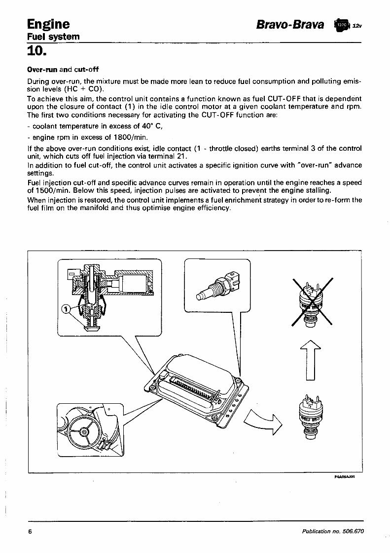
Engine Bravo-Brava iffyix, Fuel system
10. Over-run and cut-off During over-run, the mixture must be made more lean to reduce fuel consumption and polluting emission levels (HC + CO). To achieve this aim, the control unit contains a function known as fuel C U T - O F F that is dependent upon the closure of contact (1) in the idle control motor at a given coolant temperature and rpm. The first two conditions necessary for activating the CUT-OFF function are: - coolant temperature in excess of 40° C, - engine rpm in excess of 1800/min. If the above over-run conditions exist, idle contact (1 - throttle closed) earths terminal 3 of the control unit, which cuts off fuel injection via terminal 21. In addition to fuel cut-off, the control unit activates a specific ignition curve with "over-run" advance settings. Fuel injection cut-off and specific advance curves remain in operation until the engine reaches a speed of 1500/min. Below this speed, injection pulses are activated to prevent the engine stalling. When injection is restored, the control unit implements a fuel enrichment strategy in order to re-form the fuel film on the manifold and thus optimise engine efficiency.
6 Publication no. 506.670

Bravo-Brava i © t ^ Engine Fuel system
10. Lambda adjustment
The LAMBDA probe controls mixture concentration by measuring the residual oxygen content of exhaust emissions. Because the ceramic is not active below 300° C, the LAMBDA probe is heated electrically by a resistance (inside the probe) that is continually supplied by a locked positive and protected by a 10 A fuse.
This heating is necessary during cold starts to maintain sensor efficiency if the engine idles for long periods.
With temperatures in excess of 300° C, the ceramic becomes a conductor of oxygen ions. If the percentages of oxygen present on either side of the sensor differ, a voltage difference is set up across the two end poles.
The LAMBDA probe sends a voltage difference signal to the control unit through terminals (12) and (13).
LAM B DA probe measurements of exhaust gas composition allow the control unit to correct the mixture concentration continually on-line (leaner/richer) in order to maintain it close to a stoichiometric ratio. Efficient catalytic converter operation and low exhaust gas toxicity are dependent on an exact mixture composition.
During the above stages, injection pulse changes made by the control unit on the basis of the LAMBDA probe signal are excluded because they would be at odds with the required driving conditions; the engine thus operates in OPEN LOOP.
With both LAMBDA probe and control unit circuit working properly, the percentages of polluting exhaust gases are self-regulated by the system without the possibility of external regulation.
Copyright Fiat Auto 1

Engine Bravo-Brava Fuel system 10. IGNITION MANAGEMENT
The ignition system is solid-state distribution type. In other words, moving parts are eliminated by doing away with a high tension distributor (case-brush-cap). Coil (B) is fitted with four high tension outlets connected directly to the spark plugs. Their operation is managed entirely by control unit (A). The control unit contains (in addition to fuel metering control parameters) a memory map (C) containing a set of optimal advance angles that can be used by the engine according to service conditions: engine load (a) and rpm (n). The mapped values are obtained experimentally on a bench taking into account power, fuel consumption and polluting emissions. The control unit selects the appropriate advance value according to the memory maps, rpm (D), coolant temperature (E) and engine load (F), knock (G) and governs the ignition unit power module accordingly. The control unit contains three different base advance angle maps to cater for changing engine service conditions:
- full load, settings mapped according to rpm and engine load. - partial load, settings again mapped according to rpm and engine load. - idling, where settings are mapped according to rpm.
The full load and partial load advance angle may also be subject to further corrections on the basis of engine temperature and air temperature. The idle advance angle is corrected only on the basis of engine temperature (non-constant value is about 7°). The control unit contains an algorithm that computes the advance on the basis of rpm and battery voltage at which current begins to fiow into the coil primary winding.
P4A08AJ01
8 Publication no. 506.670

Bravo-Brava @ t Engine Fuel system
10. The ignition coil consists of two primary windings connected to control unit (A) via terminals 34 and 35 supplied by battery voltage, and two high tension secondary windings whose outputs are connected directly to the spark plugs of cylinders 1 -4 and 3-2. The two spark plug pairs are supplied with high voltage whenever current is cut off in the primary winding by the power module. The high tension solid state distribution exploits the different pressure conditions existing simultaneously in cylinder pairs 1 -4 and 3-2. In practice, if an air/fuel mixture is present, the compression phase of one cylinder corresponds to the exhaust phase of the other. If, under these conditions, the voltages required to set off a spark between the electrodes of a spark plug are examined, it may be noted that the voltage is very high during the compression stage ( 1 0 - 1 5 kV), but extremely low during the exhaust stage (in the order of 500 V). Two sparks therefore cross the secondary circuit of each coil. One of these generates about 500 V and is in essence a wasted spark because it is triggered in the cylinder in exhaust phase, the other generates 10 - 1 5 or more kV in the cylinder in compression-exhaust stage in order to burn the air fuel mixture in the cylinder.
ENGINE IDLE CONTROL The main aim of this strategy is to maintain engine speed at around the mapped setting (warm engine: 850 rpm): the position assumed by the actuator is dependent on engine conditions/rpm and vehicle speed.
Start-up stage When the key is inserted, the actuator takes up a position dependent on engine temperature and battery voltage (open-loop position).
Warming-up stage The rpm is mainly corrected on the basis of coolant temperature.
With the engine warm, idle management is dependent upon the signal from the rpm sensor. The E C U introduces sustained idle when external loads are activated.
When the accelerator is released when the car is not idling, the ECU governs the actuator (step motor) by measn of special delivery curve (dash-pot curve), i.e. delays the return of the plunger to its housing to bring about a reduction in engine braking effect.
F U E L VAPOUR RECIRCULATION MANAGEMENT
Fuel vapours (legally recognised pollutants) are directed to an active carbon filter and then on to the engine where they are burnt. This is achieved by means of a solenoid controlled by the ECU only when engine load conditions are appropriate for permitting effective combustion without operation being impaired. The ECU compensates for the extra fuel by reducing fuel flow to the injectors.
CONTROLLING KNOCK
This function detects the presence of knock by processing a signal from a knock sensor. The E C U continually compares signals from the sensor with threshold values, which are in turn continually updated to take into account background noise levels and engine age. The ECU is therefore able to detect the presence of knock (or incipient knock) and reduce the ignition advance until the effect disappears. The advance is then gradually restored to baseline levels.
Over-run
Copyright Fiat Auto 9

Engine Bravo-Brava igt^v Fuel system 10. When the car is accelerating, a higher threshold is used in order to take into account the increased engine noise under these conditions. The knock control strategy is also equipped with a self-adaptive facility which memorises advance reductions which are repeated regularly. In this way, the maps are adapted to the different conditions the engine encounters.
HEATING/VENTILATION S Y S T E M MANAGEMENT When the air conditioner comes on, the compressor takes up power from the engine which tends to stall when idling. To avoid this problem, the ECU adjusts air flow to the new power requirements by driving the relevant actuator (adjustment also takes place when the car is running in order to maintain optimum driveability). Another system function is to cut off the power supply to the compressor temporarily in the case of high power demands on the engine (powerful acceleration).
S Y S T E M SELF-ADAPTION The ECU comprises a self-adaptive function which recognises changes occurring in the engine due to settling and wear (this applies to the components and the engine itself). Such changes are memorised in the form of changes to the baseline maps and serve the purpose of adapting system function to gradual changes in the engine and its components as the engine grows older. This function also compensates for inevitable differences between original parts and new parts (due to production tolerances. Maximum performance is therefore achieved for all vehicles without the need for specific adjustment and test operations. Self-adaptive parameters are lost if the ECU is disconnected.
FIAT CODE IGNITION LOCK FUNCTION MANAGEMENT The system features an ignition lock function. This is implemented through a special FIAT CODE control unit able to dialogue with the engine control unit, and an electronic key with a specific sender unit designed for sending an identification code. Once the key has been turned to STOP, the FIAT CODE system de-activates the engine control unit completely. When the key is turned to MAR, the following operations take place in sequence: 1. the engine control unit (whose memory contains a secret code) sends the FIAT CODE a request de
manding that a secret code be sent to de-activate the function lock: 2. the FIAT CODE control unit responds by sending the secret code only after receiving a recognition
code sent by the ignition key; 3. recognition of the secret code allows the engine control unit lock to be de-activated and normal op
eration to proceed.
NOTE When the FIA T CODE anti-theft system is present, it is extremely inadvisable to test the vehicle using another engine control unit. In this case, the FIA T CODE control unit would transfer the recognition code (unknown) to the test control unit, which would thus be rendered completely unserviceable on other vehicles.
TEST MANAGEMENT
Full injection-ignition system electronic testing can be achieved by connecting a FIAT/LANCIA TESTER to the test socket.
The system is also equipped with a self-diagnostic function which recognises, memorises and indicates any faults. If sensors or actuators are found to be faulty, signal reconstruction strategies are immediately activated (recovery) so that the engine is able to operate at an acceptable level without affecting function. The car can then be driven to a service point for the necessary repairs.
10 Publication no. 506.670

Bravo-Brava ijp 12v Engine Fuel system
10. DIAGRAM SHOWING INPUT/OUTPUT BETWEEN ECU AND SENSORS/ACTUATORS OF THE BOSCH MONOMOTRONIC SPI INJECTION-IGNITION SYSTEM
Key to components 1. Electronic control unit 2. Coil 3. Air temperature sensor 4. Speedometer sensor 5. Lambda probe 6. Coolant sensor 7. Throttle position sensor 8. Rpm and TDC sensor 9. Ignition switch
10. Electric fuel pump
11. Injector 12. FIAT CODE control unit 13. Engine idle speed actuator 14. Rev counter 15. Fuel vapour cut-off solenoid 16. Diagnostic socket 17. Injection warning light 18. Air conditioner compressor 19. Knock sensor
Copyright Fiat Auto 11

Engine Fuel system
Bravo-Brava ! 0 i 12v
10. AIR INTAKE CIRCUIT DIAGRAM
1. Warm air intake on exhaust manifold 2. Actuator for warm/cold air deflector 3. Cold air intake fitting 4. Air cleaner
5. Thermostatic valve 6. Vacuum ducts 7. Vacuum socket 8. Throttle case
The air intake circuits comprises various components which.ensure sufficient air is carried to the engine under different service conditions. The intake of warm or cold air is selected by deflector (2) which may or may not be affected by the vacuum in the intake manifold according to position of thermostatic valve (5). More specifically, when intake air temperature exceeds 9°C, thermostatic valve (5) stays closed and does not allow the vacuum to reach actuator (2) (position B) . Viceversa, when intake air temperature drops below 9°C, the thermostatic valve (5) opens to allow a vacuum through to actuator (2) (position A).
12 Publication no. 506.670

Bravo-Brava (§1^ Engine Fuel system
10. FUEL SUPPLY CIRCUIT DIAGRAM
1. Delivery line from tank to filter 2. Fuel filter 3. Delivery line from filter to injector 4. Return line 5. Vent pipe 6. Union with vent and pressure relief valve 7. Tank 8. Electric pump 9. Pressure regulator
10. Injector
N OTE Due to the specific shape of the tank, when fuel is added, an air lock may build up at the bottom which could prevent complete filling. Pipe (6) allows air to flow from the lower part so that the tank can be filled completely.
Copyright Fiat Auto 13

Engine Fuel system
Bravo-Brava i f p 12v
10. FUEL EVAPORATION CONTROL CIRCUIT DIAGRAM
The fuel evaporation system prevents fuel vapour, mainly comprising lighter hydrocarbon fractions formed in the tank, to escape into the atmosphere.
1. Pipe carrying fuel vapour to butterfly valve case
2. Fuel vapour cut-off solenoid
3. Carbon filter
4. Pipe carrying fuel vapour from tank to carbon filter
5. Safety and ventilation valve
6. Multifunction valve
7. Tank
8. Injection-ignition ECU
9. Fuel vapour intake fitting in intake manifold
14 Publication no. 506.670

Bravo-Brava i j p t i 2 v Engine Fuel system
10. BLOW-BY GAS RECIRCULATION DIAGRAM
P4A15AJ01
The system controls emission, from the engine block, of vent gases made up of air-fuel mixtures, burnt gases which leak through piston rings and lubricant oil vapours by recirculating them to the intake.
Gases emerge from outlet (1), which contains a flame trap (5) designed to prevent combustion caused by flame flashing back from the butterfly valve case.
With the accelerator throttle open, gases are taken in upstream of the throttle through intake (3) located on the air shroud to the butterfly valve case.
With the throttle closed (engine idling), the vacuum in the intake manifold takes up gas (in limited quantities) directly through the pipe (2) and calibrated hole (4).
Copyright Fiat Auto 15

Engine Fuel system
Bravo-Brava 1 1 12v
10. INJECTION-IGNITION SYSTEM WIRING DIAGRAM
CM 8 C H W L H C
C O
C M I oc
1 —
i oc
fie
0 0
C O
p-cH v o i l -
I *
15^
® [ 3 -
co [ 3 -
o
CM
oo - t S 3 — |
T - O C M
CM — |
C M C M
C O C M
16 Publication no. 506.670

Bravo-Brava @* 12v Engine Fuel system
10. Key to components in injection-ignition system wiring diagram A. I.e. electronic control unit. 1. Earth 2. Diagnostic socket 3. Air conditioning system connection 4. System warning light 5. Rev counter 6. FIAT CODE control unit 7. Speedometer signal 8. Ignition coil 9. Knock sensor
10. I.e. system supply relay. 11. Ignition switch 12. Fuel pump and lambda probe relay 13. Battery positive (+30)
14. 10A fuse for fuel pump
15. 10A fuse for lambda probe heating coil
16. Fuel vapour cut-off solenoid 17. Electric fuel pump 18. Hot Lambda probe 19. Injector and intake air temperature sensor 20. Throttle valve position sensor
21. Coolant temperature sensor
22. Engine idle speed actuator
23. Rpm and TDC sensor
24. 30A master fuse for injection-ignition system 25. Inertia switch
Copyright Fiat Auto 17

Engine Bravo-Brava Fuel system 10. ENGINE EXHAUST ASSEMBLY DIAGRAM
P4A18AJ01
Key
1. Exhaust manifold
2. Lambda probe
3. Catalytic converter
4. Silencers
18 Publication no. 506.670

Bravo-Brava i f p i u v Engine Fuel system
10. LOCATION OF INJECTION-IGNITION SYSTEM COMPONENTS IN ENGINE BAY
P4A19AJ01
Key to components
1. Fuel vapour cut-off solenoid 2. Carbon filter 3. 10A fuse for pump and injection-ignition
system 4. Throttle position sensor 5. Pump and injection-ignition system re
lays 6. Injector 7. Air temperature sensor 8. Fuel pressure regulator 9. Engine idle speed actuator
10. Diagnostic socket 11. Lambda probe 12. Injection-ignition ECU 13. Joint between injection lead and front
lead 14. General 30A system fuse 15. Coolant temperature sensor 16. Ignition coil 17. Rpm and TDC sensor 18. Knock sensor 19. Earth
Copyright Fiat Auto 19

Engine Fuel system
Bravo-Brava igai 12v
10. INJECTION SYSTEM FUSES AND RELAYS
General system protection fuse The general fuse (EFI-30A) protecting the injection-ignition system (1) is housed inside a container; to gain access to the fuse, undo side clips and lift lid.
Fuses and relays
The following components are housed on a bracket located against the rear wall of the engine bay: 1. 10A fuse for fuel pump
2. 10A injection-ignition system fuse
3. Injection-ignition system relay
4. Fuel pump relay
Unscrew ring nut and remove cover to gain access to the above components.
EARTH POINT The earth of the injection-ignition system is fixed at the right rear of the engine, close to the first cylinder spark plug.
20 Publication no. 506.670

Bravo-Brava !§| 12v Engine Fuel system
10. COMPONENTS OF INJECTION-IGNITION SYSTEM
The injection-ignition system consists mainly of wiring, an electronic control unit (i.e. ECU) and the following sensors and actuators:
- Lambda probe sensor
INJECTION-IGNITION SYSTEM WIRING The various system components are connected by a single wiring system fitted with connectors of various types. These are grouped in special ducts fitted to the engine (prewiring).
INJECTION-IGNITION ECU (0.261.203.868) The ECU analyses data on engine service conditions transmitted by the sensors. Input signals from peripheral sensors are processes and injector/ignition timing pulses are governed with the aid of programmed typical curves. The ECU is connected to the system by means of a 35 pin connector and protected by false polarities and circuit-breakers. The ECU is able to detect when sensors are not working efficiently and replace incorrect or missing data with data taken from certain areas of its memory in order to ensure engine operation even under emergency conditions. It is also equipped with a full SELF-DIAGNOSTIC strategy for both input and output sensors. It also contains a special memory able to record any faults received during testing. When a Fiat/Lancia TESTER is connected to the system it is therefore possible to test or display any errors stored in the memory. Another important feature of the ECU is self-adaption. This function allows the system to recognise various changes (ranging from atmospheric changes to changes due to component wear) which could impair efficient engine operation and adjust to them by implementing appropriate strategies.
Sensors - Speedometer sensor - Rpm and TDC sensor. - Knock sensor - Coolant temperature sensor - Throttle position sensor - Intake air temperature sensor
Actuators - Engine idle speed actuator - Fuel vapour cut-off solenoid - Electric fuel pump - Injector - Ignition coil - Spark plugs
Disconnect electrical connection. Undo retaining nuts and remove ECU.
Removing-refitting control unit
It is absolutely prohibited to exchange injection control units between different vehicles in order to check their efficiency.
Before replacing an ECU as a result of testing, ensure it is really faulty because when a new ECU is activated, the secret Fiat CODE system code is memorised and this makes the unit completely unusable on other vehicles.
P4A21AJ01
Copyright Fiat Auto 21

Engine Bravo-Brava Ifyi* Fuel system 10. IDENTIFYING CONNECTIONS ON CONTROL UNIT (PIN-OUT)
P4A22AJ01
1. I.e. system supply relay. 2. Diagnostic socket 3. Engine idle speed actuator 4. Not connected 5. Not connected 6. FIAT CODE control unit 7. Intake air temperature sensor 8. Coolant temperature sensor 9. Throttle position sensor
10. Throttle position sensor 11. Power source for coolant temperature
sensor, throttle position sensor and intake air temperature sensor
12. Lambda probe 13. Lambda probe 14. Knock sensor 15. Knock sensor 16. Rpm and TDC sensor 17. Rev counter signal
18. Speedometer sensor 19. Power supply (+30) 20. Engine earth 21. Injector 22. Not connected 23. Air conditioning system connection 24. Throttle position sensor 25. Fuel pump and lambda probe relay 26. Fuel vapour cut-off solenoid 27. Not connected 28. Injection system failure warning light 29. Engine idle speed actuator 30. Engine earth 31. Engine idle speed actuator 32. RPM and TDC sensor 33. Engine earth 34. Ignition coil 35. Ignition coil
22 Publication no. 506.670

Bravo-Brava 12v Engine Fuel system
10.
1. Rpm sensor
2. Toothed pulley
3. Engine flywheel
RPM AND T D C S E N S O R (0.281.002.102) The sensor responsible for measuring rpm and TDC is inductive, in other words it works by means of changes in a magnetic field generated by teeth passing in front of a toothed pulley (phonic wheel) situated inside the engine block. The sensor is thus fastened to the engine block and it is no longer necessary to check and adjust gap or angular position. The passage of teeth in front of the sensor alter the gap between pulley and sensor. The dispersed flow alters as a result to set up an alternating voltage with amplitude dependent on rpm.
The phonic wheel consists of 58 teeth plus a space equivalent to the gap left by two missing teeth.
The reference point defined by the gap left by two missing teeth is used as a basis for recording synchronism point (TDC). Refer to Fuel System section for the 1581 16v engine for a more detailed description of sensor operation.
Removing - ref itti ng Position vehicle on a lift, then work from below the vehicle and proceed as follows:
- Disconnect electrical connection; - unscrew screw retaining sensor and with
draw from housing.
Wiring connector The sensor is connected to the ECU (pin 16 e 32) by means of twisted wires covered by an earthed interference-proof shielded sheath.
NOTE The numbers in boxes indicate the corresponding gpntroi unit pins.
Checking resistance
Sensor resistance may be measured by disconnecting the connector and connecting an ohmmeter to the sensor terminals. Resistance: 774-946 ohm at 20 C
Copyright Fiat Auto 23

Engine Fuel system
Bravo-Brava © 12v
10.
Be sure to take the measurement at right angles to the phonic wheel and at the point of a tooth, not a depression.
Checking gap
Because the rpm and TDC sensor is secured directly to the engine block, gap and angular position do not require adjustment. If a fault is suspected, the gap can be checked as follows:
- remove the rpm and TDC sensor; - check that the distance between the sensor
contact surface and phonic wheel tooth corresponds to the sum of sensor probe length ( 3 4 . 5 mm) and gap ( 0 . 8 - 1 .5 mm).
KNOCK SENSOR (0.261.231.007)
The knock sensor is located on the rear of then engine block, between cylinders 2 and 3 .
Refer to the fuel system section for the 1 9 9 8 2 0 V engine for a more detailed description of operation.
Recovery Ignition advance delay: 8° - 9° according to engine speed. Knock control deactivation If the fault relates to the sensor interface circuit, the ECU assumes an ignition advance delay of 1 0 ° .
Wiring connector
The numbers in boxes indicate the corresponding control unit pins.
24 Publication no. 506.670

Bravo-Brava \^±2v Engine Fuel system
10. THROTTLE CASE (0.438.201.523) All the components of the aluminium butterfly valve case or injector turret are highly miniaturised and the unit is extremely compact. Most system sensors and actuators are fitted to this unit:
1. Fuel intake fitting 2. Fuel return fitting 3. Accelerator throttle position sensor (potentiometer) 4. Fuel pressure regulator 5. Intake air temperature sensor 4. Injector 7. Director current motor for idle speed control 8. Throttle closed recognition microswitch incorporated in motor (7) 9. Throttle position adjustment screw (do not touch)
10. Crankcase oil vapour recirculation fitting (BLOW-BY) 11. Fitting for intake of fuel vapour from carbon filter through cut-off valve 12. Fitting for thermal valve control vacuum on air cleaner
P4A25AJ02
I
Copyright Fiat Auto 25

Engine Bravo-Brava Fuel system 10. Throttle angular opening sensor
The angular position signal (a) from throttle (1) plays a fundemental role in determining base pulse constant. This signal is recorded by a dual-race potentiometer (2) fitted to butterfly valve case by means of a brush with two double rows (4) integral with the throttle valve spindle (5). The throttle sprindle is fitted on two ball bearings (6) to prevent binding or errors when measuring angle a.
The position of potentiometer (2) is adjusted in relation to the butterfly valve in the factory and should never be removed for any reason. Replace butterfly valve case assemby if found to be faulty.
P4A26AJ01
The ECU (A - see figure overleaf), supplies terminal 5 of the throttle angular opening sensor (B) with a stabilised reference voltage of 5 V (constant) through terminal 24.
A voltage signal measured on the first race (C) is sent to terminal 9 of the ECU from terminal 2 of the potentiometer. This is proportional to the positions taken up by the throttle during the first 24° (0° - 24°) of opening.
26 Publication no. 506.670

Bravo-Brava ffl 12v Engine Fuel system
10.
18° 24° M A X a (°)
The signal therefore assumes a value close to 0 Volt when the throttle is completely closed, and a value close to 5 Volt for an opening of 24° in relation to rest position. The throttle opening range from 0° - 24° corresponds to tend reference points in the ECU map (a). These represent the ten main positions taken up by the throttle valve. In this way, the ECU may recognise small angular changes in the order of 2°25'. This high degree of sensitivity allows the ECU to select base pulse constant from the specific maps with greater precision under critical engine service conditions, i.e. when idling and under partial load. From 18° of throttle opening up to full opening (about 90°), a signal is produced by terminal 4 of potentiometer (B), i.e. terminal of second race (D). This signal is sent to terminal 10 of the ECU and relates to engine service conditions at medium and full loads. The field of the second race is divided into ECU maps a with lower resolution than the first race, i.e. into 5 points corresponding to angular throttle changes of about 13°. The entire opening range of the throttle valve therefore corresponds to 15 significant points or openings (alpha). These are identified by the ECU by means of two potentiometer races. With throttle valve opening angles between 18° and 24°, both voltage signals present simultaneously at terminals 2 and 4, first and second race respectively, should respect a certain ratio. Under the above conditions, the ECU runs a plausibility check to test signals from the first race (C - minimum/partial load) are perfectly synchronised with those of the second (D - medium/full load). Terminal 1 of the potentiometer is earthed through terminal 11 of the ECU.
Copyright Fiat Auto 2 7

Engine Bravo-Brava igSt v Fuel system 10. Recovery The potentiometer emergency/safety function is activated when faults prevent the ECU from measuring the actual throttle openng angle (a).
- when race 1 of the potentiometer is faulty, predefined safety injection times and ignition advances are set. The idle regulation motor is set to an emergency position.
- when race 2 is faulty, only a safety injection time and a safety ignition time are set. - when synchronisation is faulty, the last data item saved is set as the offset between both races.
Direct current motor for idle speed control Idling rpm level is adjusted automatically by the ECU through a 12 V direct current electric motor (A). This acts directly on linkage (B) of the throttle control valve through a reduction system. The throttle opening motor incorporates a microswitch (C), which is closed when the accelerator pedal is at rest (released). Contact closure activates the two-fold CUT-OFF function during over-run and automatic idle adjustment. —
P4A28AJ01
Injection pulses are restored after a period of CUT-OFF and idle speed regulation is activated by the ECU (A see figure overleaf), mainly on the basis of rpm and coolant temperature. The electronic system is also able to take into account other parameters, namely: engine in start-up or or warm-up mode, air conditioner activated. The idle control function is activated by closure of contact (C see figure overleaf) which connects terminal 3 of the ECU to earth through terminals 3 and 4 of the connector of motor (B) at point (I). Whenever necessary, the ECU supplies regulation motor (D) through terminals 29 and 31 so that the throttle valve opens and closes to correct idle speed. An electronic switch inside the ECU reverses motor polarity in order to produce two directions of rotation (clockwise and anticlockwise).
28 Publication no. 506.670

Bravo-Brava iggi Engine Fuel system
10. When motor (D) is activated, the reduction unit is set in rotation. This consists of a worm screw (E) and helical gear (F). The helical gear contains a worm screw which microswitch case (G) moves along in both directions so that the case can move in and out according to wheel rotation direction. At the end of its travel, plunger (H) acting on throttle valve linkage can bring about a maximum opening of about 18°.
// a fault has been established, the idle control motor can be obtained as an individual part.
P4A29AJ01
Recovery
In the case of an error on the idle contact (short circuit or circuit open) the ECU implements one of two strategies according to time of recognition: - recognition (circuit open) when key is positioned on MAR, no recovery value obtained (ignored); - recognition (short circuit or circuit open) with key set to MAR, the ECU drives the d.c. motor to a safe
ty position (throttle in idling position).
In the case of an error on the motor (locked or defective, drive stage broken or defective), revealed by a comparison between drive value and actual position under actual idling contact conditions, the ECU activates an rpm limitation, which ranges from 1400 to 2000 rpm.
Copyright Fiat Auto 29

Engine Bravo-Brava iffii*, Fuel system 10. Injector
The injector performs the function of nebulizing the fuel necessary for forming the fuel mixture. It is made out of stainless steel for more effective resistance to any impurities present in the fuel. It is connected in a central position on the injector turret above the butterfly valve.
It consists of an outer case (1) containing coil (2) with a ferromagnetic core (3) and spring (4), which performs the task of holding plunger (5) closed against the seat on bcase (6). The assembly is completed by other parts: electrical contacts (7), fuel intake channel (8) with filter (9), fuel outlet channel (10) and filter (11). Control pulses from the ECU reach the injector through electrical contacts (7) to set up a magnetic field about core (3) through winding (2). Plunger (5) then lifts from its seat to overcome the load of counter-spring (4) and bring about injector opening. Plunger height is 0.06 mm (height x); If physical fuel properties are constant, the amount injected depends solely on injector opening time (injection time), which is established by the ECU according to engine service conditions. The fuel jet leaves the injector at a pressure of about 1 bar, is immediately nebulized to form a cone of 30° - 90° and injected upstream of the accelerator throttle. Injector control is synchronous, i.e. one injection per ignition command. A hole (12) on the accelerator throttle is designed to optimise mixture distribution within the intake manifold while the engine is warming up.
P4A30AJ01 P4A30AJ02
30 Publication no. 506.670

Bravo-Brava Engine Fuel system
10. A positive injector supply current is supplied through the fuel pump relay; the circuit is earthed in the control unit via terminal 21.
P4A31AJ01
Fuel pressure regulator The mechanical diaphragm regulator (1) is fitted in the injector turret (2). The function of the fuel pressure regulator is to maintain fuel feed pressure to the injector at a level of about 1 bar. Fuel under pressure from the electric pump reaches hydraulic chamber (3) of the pressure regulator. If pressure on membrane (4) exceeds a level of 1 bar, it overcomes the load on counter-spring (5), and moves plate (6) to allow fuel to flow out through a channel (7) in the tank. Hole (9) in the top chamber (8) of the regulator brings chamber 8 into communication with the outside so that a vacuum does not build up inside the chamber. When the engine stops, fuel feed is also shut off. The pump check valve and injector close. In this way, feed pressure is maintained for a certain period in the hydraulic section.
P4A31AJ02
This form of operation prevents the formation of vapour bubbles as a result of fuel in the system being heated by the engine to ensure trouble-free starting at all times.
Copyright Fiat Auto 31

Engine Bravo-Brava Fuel system
10. Intake air temperature sensor
Intake air temperature is measured by temperature sensor (B) located on the butterfly valve case.
This sensor consists of a plastic case on which is located the reactive element (1), which consists of a resistance (N.T.C.) that varies in inverse proportion to temperature.
If temperature is between 15° C - 30° C, resistance is 3.3 -1 .5 kCl. If temperature is about 80° C, the resistance is 0.280 - 0.360 O.
Terminal 13 of the ECU (A) supplies terminal 1 of sensor (B); the circuit is earthed from terminal 2 of the sensor to terminal 27 of the ECU.
When the sensor is disconnected, the ECU supplies a voltage of 5 V. With the sensor connected, the supply voltage alters according to temperature (internal sensor resistance).
Recovery
When the air temperature sensor is short-circuited (d.c.) or circuitis open (a.c) , the ECU receives implausible signals, i.e.:
- d.c. sensor: air temperature > 128° C - a.c. sensor: air temperature < -50° C
In these cases, the ECU implements a Recovery strategy which takes an air temperature of 20° C as a reference.
32 Publication no. 506.670

Bravo-Brava ifp 12v Engine Fuel system
10. COOLANT TEMPERATURE SENSOR (0.280.130.026)
The coolant termperature sensor (B) consists of a variable N.T.C. resistance. It is fitted on the thermostat case and works in a similar way to the intake air temperature sensor.
Terminal 8 of ECU (A) supplies sensor (B). The circuit is earthed through the sensor terminal to terminal 11 of the ECU.
80 100 120
Checking resistance The graph in the figure shows the sensor resistance curve, which may be measured by disconnecting the connector and connecting an ohmmeter to the sensor terminals. Removing - ref itti ng Disconnct the electrical connection and remove the sensor.
Tightening torque 2.4 daNm.
Copyright Fiat Auto 3 3

Engine Bravo-Brava Fuel system 10. Recovery
- with coolant temperature sensor disconnected, short circuited (d.c.) or with circuit open (a .c ) , implausible signals reach the ECU, i.e.:
- d.c: coolant temperature > 96.5 °C - a .c: coolant temperature < 96.5 °C - false contact: when temperature drops occur between two successive temperature samples and the
deviation is too great. - implausible signal: with coolant temperature < +60° C, and engine running, sensor output signal
does not change.
If the ECU records one or more signals as above, the RECOVERY strategy is implemented:
- with air temperature < 24° C, the ECU considers coolant temperature to be equal to air temperature for about 4 minutes. After this, coolant temperature is assumed to be 100° C;
- with air temperature > 24° C, the E C U considers coolant temperature to be 100° C.
ELECTRIC FUEL PUMP (0.580.453.514) The fuel pump, submerged in the tank, is a two-stage turbo pump and integral with the fuel level gauge assembly-. The pump is designed to work with a 12 V supply, at a nominal pressure of 1.1 ± 0.1 bar providing an output of 100 litres/hour. The advantages of low pressure turbo pumps compared to high pressure pumps (2.5 bar), are: small size, reduced weights and low noise levels.
P4A34AJ02
The electric pump contains an impeller (1) that turns two sets of blades: an inner set (2) with lateral profile and an outer set.(3) with peripheral profile. When field coil (4) turns, fuel is taken into the first stage with lateral profile. It then flows through a channel in intake disc (5) to the second stage where it picks up speed and is sent on to the injector turret through outlet case (6) and antireflux valve (7).
The electric pump is supplied by the electronic control unit via a relay and 10A fuse. NOTE Refer to fuel system section for the 1581 16V for location and removal-refitting procedure.
34 Publication no. 506.670

Bravo-Brava ipi^ Engine Fuel system
10. F U E L F ILTER (A.450.024.262) The fuel filter is fitted under the floor pan, along the fuel delivery line. Refer to fuel system section in 1581 16V manual for location and removal-refitting procedure.
P4A3SAJ01
IGNITION COIL (0.221.503.407)
The closed magnetic loop coil is fastened to the left hand side of the cylinder head cover.
1. HT socket for cylinder no. 1 spark plug 2. HT socket for cylinder no. 2 spark plug 3. HT socket for cylinder no. 3 spark plug 4. HT socket for cylinder no. 4 spark plug 5. LT socket for ECU connection
Checking winding resistance Primary circuit (A cylinders 2-3, B cylinders 1-4) Bring the terminals of an ohmmeter into contact with positive strip (central pin) and negative strip (pin 1 for circuit A and pin 2 for circuit B) respectively.
The primary circuit resistance reading on the guage should be between 0.45 and 0.55 ohm at 23 °C.
Secondary circuit (C cylinders 1 -4, D cylinders 2-3) Bring the terminals of an ohhmeter into contact between the two high tension outlet ter-
Ylieasecondary circuit resistance reading on the gauge should be between 12000 and 14600 ohm at 23 °C.
Removing refitting
Disconnect HTand LT connections, then unscrew retaining screws and remove the coil.
Connector wiring
NOTE The numbers in boxes indicate the corresponding control unit pins.
Copyright Fiat Auto 35

Engine Fuel system
Bravo-Brava 12v
10.
P4A004B02
Wiring connector
The numbers in boxes indicate the corresponding control unit pins.
LAMBDA PROBE (0.258.003.466)
The vehicle is fitted with a four channel hot lambda probe which measures exhaust gas oxygen content. Refer to Fuel System section in the 1581 16V manual for a full description of the lambda probe
A The probe may be swiftly put out of service by the presence of even slight amounts of lead in the fuel.
Removing-refitting - Place the vehicle on a lift.
- Disconnect battery negative lead.
- Raise the vehicle - Disconnect electrical connection
- Remove the lambda probe from its seat.
- When tightening, do not force the component or it could be irreparably damaged.
A If fitting a new lambda probe, spread threaded part with anti-seize graphite grease (e.g. Bosch VS 14016- FT).
Tightening torque 5 - 6 daIMm
Checking resistance Probe heater resistance may be measured by disconnecting connector and connecting an ohmmeter as shown in the figure.
Resistance: 4.5 ± 0.5 ohm at 20 °C
36 Publication no. 506.670

Bravo-Brava i ^ i *
P4A36FJ02
Engine Fuel system
10. CARBON FILTER AND FUEL VAPOUR CUT-OFF SOLENOID
The carbon filter and solenoid are located in the right hand wheel arch compartment.
For a description of the carbon filter refer to Fuel System section of the 1581 16V manual.
For a description of the fuel vapour cut-off solenoid and removal-refitting procedures for filter and cut-off solenoid, refer to Fuel System section of 1998 20V manual.
1. Vapour cut-off solenoid 2. Carbon filter
Vapour cut-off solenoid (0.280.142.300)
Wiring connector
NOTE The numbers in boxes indicate the corresponding control unit pins.
S P E E D O M E T E R SENSOR
The speedometer sensor (vehicle speed sensor) consists of a Hall-effect sensor located on the differential output. The sensor sends the ECU a signal, whose frequency alters according to vehicle speed.
The ECU uses this information for more effective idle adjustment actuator management.
P4A37AJ03
Copyright Fiat Auto 37

Engine Fuel system
Bravo-Brava ffi 12v
10. INERTIA SWITCH
The vehicle is equipped with an inertia switch located inside the passenger compartment beneath the driver's seat.
This sensor reduces the possibility of fire (caused by fuel emerging from the injection system) by de-activating the fuel feed pump.
For a full description and removal-refitting procedure, refer to Fuel System section of the 1581 16V manual.
After even an apparently light collision, if a smell of petrol is noted or fuel leaks are seen, do not activate the switch again until the fault has been found and corrected in order to avoid the risk of fire.
MULTIFUNCTION VALVE AND SAFETY AND VENTILATION VALVE
These valves belong to the evaporation control and fuel vapour recirculation system. For a description of operation, refer to Fuel System section of the 1581 16V manual.
38 Publication no. 506.670

Bravo-Brava @t 12v Engine Fuel system
10 CHECKS, ADJUSTMENTS AND REPAIRS TO BOSCH MONOMOTRONIC SYSTEM
OBSERVE THE FOLLOWING PRECAUTIONS WHEN WORKING ON VEHICLES WITH BOSCH MONOMOTRONIC INJECTION-IGNITION SYSTEMS:
- never start the engine when the electrical terminals are poorly connected or loose on the battery poles;
- never use a quick battery charger to start the engine;
- never disconnect the battery from the car circuit with the engine running;
- when charging the battery quickly, first disconnect the battery from the vehicle circuit;
- if the vehicle is placed in a drying oven after painting at a temperature of more than 80° C, first remove the injection I ignition ECU;
- never connect or disconnect the ECU multiple connector with the ignition key in MAR CIA position;
- a/ways disconnect battery negative lead before carrying out electrical we/ding on vehicle.
- Note that the memory of this system is active at all times (memory on stand-by), and contains all learnt self-adaptive parameters. Because all this information would be lost if the battery were disconnected, this operation should only be carried out when absolutely essential.
CHECKING FUEL SUPPLY CIRCUIT
Test i Check fuel regulation pressure as follows:
- Disconnect fuel delivery line to injector turret (from fuel filter) from inlet duct;
- Interpose pressure gauge 1895890000 between the disconnected pipe end and the fuel manifold with cocks (A) and (B) open.
- Activate fuel pump with engine off.
P4A39AJ01
The last operation is carried out by selecting "fuel pump" test on a Fiat/Lancia tester.
Under these conditions, the pressure gauge reading should stabilise at 1.1 ± 0.1 bars.
If pressure is insufficient, carry out the test 2.
Copyright Fiat Auto 39

Engine Fuel system
Bravo-Brava @ i 12v
10.
Test 2
Testing maximum fuel feed pressure (or pump efficiency)
Same connections as previous test.
- Close fuel cock lever (A);
- operate the pump with the engine off, as described previously: pressure should not exceed 5 bar (pump pressure relief valve setting). Otherwise, replace the pump because it is defective.
If pressure measured in test 1 (see previous page) exceeds 1.1 ± 0.1 bar proceed as follows:
- disconnect fuel return pipe (at point (1) for connection to rigid fuel return line to pump) and place in a container suitable for collecting the fuel.
- operate the fuel pump with engine idling, then take pressure reading off pressure gauge:
a) if it reaches 1.1 ± 0.1 bar replace the fuel return pipe to the tank because it is blocked or kinked;
b) if it exceeds 1.1 ± 0.1 bar replace the pressure regulator because it is defective.
Test 3
Checking injector seal To check for drips from the injectors, connect as described in first test (regulation pressure check) and then operate the pump with the engine off. When the regulation pressure is reached, close control lever B so that fuel pressure and injection pressure is the same.
Then: - turn off the pump; - see whether pressure remains constant for 60 seconds after stabilising (i.e. dropping slightly). - After supplying the pump with the engine off, look to see whether any of the injectors or connection
sections are dripping. Replace any dripping injectors and/or repair the defective seal in the leaking joint.
40 Publication no. 506.670

Bravo-Brava ! g|i2v Engine Fuel system
10. ADJUSTING B U T T E R F L Y VALVE OPENING CONTROL
P4A41AJ01
The butterfly valve opening linkage must be adjusted properly for the Monomotronic injection system to work properly.
Check that block (3) is fully home with link (1) disconnected from lever (2). Under these conditions the accelerator control cable should never be taut or excessively slack so that accelerator pedal free travel is taken up. If pedal shows free travel, adjust accelerator control cable nut and lock-nut. Connect link (1) to head of lever (2) and warm up engine.
With accelerator pedal released (butterfly valve closed) check clearance between levers (2) and (4) is 0.2 - 0.5 mm.
If the above clearance is not as specified, loosen nuts (5) and (6) and tighten/loosen gauge (7) on link (1). After adjustment, check that butterfly valve is fully open with accelerator pedal pressed fully down.
Copyright Fiat Auto 41

Engine Fuel system
Bravo-Brava 12v
10.
REMOVING-REFITTING VALVE CASE
BUTTERFLY
1. Disconnect the air shroud and blow-by gas recirculation lines by unfastening at the points indicated.
2. Disconnect fuel lines, evaporation control line and vacuum duct
3. Disconnect electrical connections
4-5 Release accelerator link by unscrewing the screws indicated and remove the butterfly valve case.
P4A1SAX03
42 Publication no. 506.670

Bravo-Brava Engine Fuel system
10. CHECKING ENGINE IDLE S P E E D If engine speed is not 850 ± 50 rpm, because the injection-ignition system is self-regulating, no adjustment can be carried out. It is therefore necessary to check that the accelerator linkage is properly adjusted and then search for the fault through full diagnosis using a Fiat/Lancia Tester.
CHECKING L E V E L S OF POLLUTING EMISSIONS The Monomotronic system is self-adaptive and thus constantly monitors idle speed and CO levels. Therefore there is no need for manual adjustment (adjustment screws are no longer fitted). However, checking exhaust contents downstream of the catalytic converter can provide useful information about the injection-ignition system condition, engine and catalytic converter parameters
Checking CO and HC levels when idling Measure levels of carbon monoxide (CO) and unburnt hydrocarbons (HC) with the catalytic converter hot (300 - 350 °C) (it is advisable to push the car engine on the road for about 5-10 minutes to ensure that the catalytic converter reaches service temperature). Then fit the probe of a suitably calibrated tester to at least 30 cm as indicated in the figure.
If the shape of the exhaust tail pape will not allow the probe to be fully inserted, add an extension pipe designed to ensure a seal in the joint area.
1. Check that CO and HC levels are as specified in the table; 2. If CO level is not as specified, check that:
- Lambda probe is working properly, with the aid of a Fiat/Lancia Tester; - for air leaks in the area surrounding the lambda probe seat - the injection and ignition system (particularly for spark plug wear).
3. If HC level is not as specified, the engine is not properly tuned or the catalytic converter is not efficient.
CO (%) HC (p.p.m.) C02 (%)
< 0.35 ^ 90 ^ 13
Summary table showing emission level tolerances downstream of converter
Copyright Fiat Auto 4 3

Engine Bravo-Brava @ n * v
Fuel system 10. DIAGNOSIS
Full system diagnosis can be carried out by means of active diagnosis using a Fiat/Lancia Tester
If a sensor fault is recorded, the ECU replaces the input from the faulty sensor with information from its memory (recovery) to allow the engine to continue running. When a fault is recorded, it is saved permanently and the sensor excluded from the system until the signal is again compatible.
The same procedure is applied if the fault affects an actuator or an actuator control port. When a fault is recorded and the signal replaced by a recovery input, the fault is indicated by a warning light coming on on the control panel.
The ECU is able to manage the following parameters in the case of failure: idle adjustment actuator, coolant temperature sensor, butterfly valve position sensor, air temperature sensor and knock sensor. If required by an operator, anomalies may be read off the ECU using a Fiat/Lancia Tester.
Recording faults This is carried out while running the basic function used to manage the sensor/actuator.
Memorising error and structure of error memory
Errors are memorised in the ECU in the order in which they occur in the RAM. Location and a frequency counter are memorised for each one.
Defect classification If a defect is recognised for the first time and the error status persists for the recognition time, the defect is memorised as "permanent". If this defect then disappears, it is memorised as "intermittent". If it reappears, it again becomes "permanent".
Classification of a fault as "permanent" activates recovery functions: when the fault disappears, normal reading or activation function is restored.
Some fault types are classified as "important", i.e. significant as far as emission control regulations are concerned. A warning light comes on on the control panel when these faults occur.
Frequency counter A frequency counter is allocated to each error to determine the moment at which a fault no longer present was memorised. When the fault is first detected, the frequency counter memorises a value of 10. If the fault disappears it is memorised as intermittent and the counter is decreased whenever the car is started without the fault reappearing; if the counter reaches 0, the fault is deleted automatically from the memory.
If the fault reappears after the counter has been reduced, the counter is always reset to 10 (or remains unchanged if alredy greater than 10).
Fault notification A warning light comes on when a defect is saved as "present" and "important".
The delay between recording of the fault and the warning light coming on is 2.5 secondi; the delay between the fault disappearing from the memory and the warning light going off is 0 seconds.
The warning light comes on whenever the ignition key is turned to MAR. The warning light goes off after 4 seconds unless "important" faults are present.
44 Publication no. 506.670

Bravo-Brava ijpi2v Engine Fuel system
10. Deleting errors
When the frequency counter reaches 0, the fault and associated parameters are deleted.
The entire error memory is cleared immediately in the following cases:
- by means of a "clear error memory" command sent by the tester;
- by interrupting ECU supply (by disconnecting the battery or ECU connector).
Diagnosis using Fiat/Lancia tester
Connect the Fiat/Lancia Tester (F.LT.) to a socket beside the ECU.
Information is exchanged between ECU and Tester via a two-way serial line (line K) using standard Bosch communication Protocol.
The Tester is able to perform the following functions:
- Error display;
- Engine parameter display;
- Active diagnosis
List of errors
RPM sensor
Throttle potentiometer
Air temperature sensor Coolant temperature sensor
Lambda probe
Incorrect signal (circuit open) Loss of synchronism (implausible signal)
Race 1 defective - Race 2 defective - Synchronisation error between races A.C.-D.C. A . C - D . C - False contact - Implausible signal
A . C . - D . C - Limit reached for lambda reconstruction and self-adaptive factor
Idle speed actuator Control unit
Detonation sensor Fiat CODE
A.C.-D.C.
ECU memory anomalies indicated
A . C . - D . C Code not recognised or not received
Copyright Fiat Auto 45

Engine Bravo-Brava ©U2v Fuel system 10. Displayed parameters
Engine rpm Injection time Inlet air temperature Coolant temperature Throttle valve opening angle (race 1 angle, race 2 angle, standard angle and relationship between races) Lambda probe (status, reconstruction value, self-adaptive value and probe signal activated) Fiat CODE (status byte)
Active diagnosis
The Fiat/Lancia Tester can be used to run the following tests: - Injector - Fuel vapour cut-off solenoid - Rev counter - Idle speed actuator - Error deletion.
Recovery
In the event of sensor malfunction, the ECU replaces the value transmitted by the sensor with a 'Recovery' value. This is stored in the ECU for use in the case of certain faults or may be reconstructed approximately on the basis of other available information, thus allowing the vehicle to be driven to a service centre. The value is also relayed to the Fiat/Lancia tester, and therefore it should be noted, when diagnosing, that in the event of a malfunction, the Fiat/Lancia tester indicates an error in the affected sensor and displays the recovery value.
Permanent memory The control unit has a permanent memory, which keeps a record of the error even after its cause has been eliminated, or after the key has been turned to STOP; and a temporary, volatile memory (RAM), which loses error details as soon as the underlying cause has been removed.
This will allow more effective identification of occasional errors. Before completing tests on «permanent» memory content, delete using a Fiat/Lancia Tester in Active diagnosis mode.
Otherwise, when reconnected, the tester will still display errors from a previous diagnosis.
Disconnecting the control unit from the system, even for a long period, does not delete the "permanent" memory.
46 Publication no. 506.670

Bravo-Brava ifit 16v Engine Contents
10. page
- Engine idle speed actuator 35 - Absolute pressure sensor 37 - Coolant temperature sensor 38 - Electric fuel pump 39 - Fuel filter 41 - Fuel manifold 42 - Fuel pressure regulator 43 - Carbon filter and fuel vapour
cut-off valve 43 - Multifunction valve 45 - Vehicle speed sensor 46 - Safety and ventilation valve 46 - Injectors 47 - Inertia safety switch 48 - Ignition coils 49 - Dual relay 51 - Lambda probe 53
CHECKS, ADJUSTMENTS AND REPAIRS TO IAW INJECTION/IGNITION SYSTEM. 56
INTEGRATED INJECTION-IGNITION SYSTEM M. MARELLI-WEBER I.A.W.-1AF.13 - Introduction
SYSTEM OPERATING STRATEGIES
page
- Signal management 2 - Injection management 3 - Fiat CODE anti-theft function manage
ment - 8 - Ignition management 9 - Engine idle control 12 - Fuel vapour recirculation management 12 - Test management 12 - Heating/ventilation system management 13
Diagram showing Input/output between injection-ignition system sensors/actuators 15 Air intake circuit management 15 Fuel supply circuit diagram 16 Fuel evaporation control circuit diagram 17 Blow-by gas recirculation diagram) 18 Engine exhaust assembly diagram 19 Injection-ignition system wiring diagram 20 Location of injection-ignition system components in engine bay 22
INJECTION SYSTEM FUSES AND RELAYS 23
Adjusting throttle cable 56 Removing-refitting fuel manifold with injectors and pressure regulator 56 Checking fuel supply circuit 58 Checking engine idle speed 60 Checking levels of polluting emissions 60
EARTH POINTS 23
COMPONENTS OF INJECTION-IGNITION SYSTEM 24
Injection-ignition system wiring Injection-ignition ECU Rpm and T D C sensor Timing sensor Throttle case Throttle position sensor Intake air temperature sensor
24 24 28 30 31 32 34
DIAGNOSIS 61
- System self-diagnosis 61 - Diagnosis using a Fiat/Lancia Tester 61 - Displayed parameters 62 - List of errors 62 - Active diagnosis 63 - Recovery 63 - Permanent memory 63
Copyright Fiat Auto
Bravo-Brava M^ie, Engine Fuel system
10. M.MARELLI-WEBER I.A.W.-1 AF.13 INTEGRATED INJECTION-IGNITION SYSTEM
Introduction
The I.A.W.-1 AF.13 system (I.A.W.-1 AF.23 for versions with automatic transmission) The Hitachi system fitted to the 1581 i.e. 16v engine belongs to the category of digital electronic ignition systems with static advance and timing, integrated with a phased, multipoint, intermittent electronic fuel injection system. This system therefore adopts a single ECU, single wiring system and a set of sensors common to both systems. Its function is therefore to inject an exact quantity of fuel into the engine intake duct upstream of the intake valves in order to obtain the correct mixture concentration.
The I.A.W.-1 AF.13 system ensures efficient operation and optimisation of performance and fuel consumption. Harmful emission levels are reduced through real time response to the various engine operating conditions.
The system may be divided schematically into the following subsystems:
- Electric/electronic circuit - Air intake circuit - Fuel feed circuit - Emission control devices The system is able to monitor the following parameters by means of dedicated sensors:
1. instantaneous engine rpm; 2. position of each piston pair in relation to TDC of cylinder 1; 3. intake air temperature; 4. throttle valve angular position; 5. coolant temperature; c. actual mixture concentration (by means of lambda probe signal); 7. intake manifold pressure; 8. vehicle speed; 9. battery voltage;
10. air conditioner compressor activation (if fitted).
This data, generally analogue, is converted into digital signals by analogue/digital (A/D) converters so that it may be used by the ECU. Note that this I.A.W.-IAF.13 injection-ignition sytem does not require adjustment because it is self-adjusting and self-adaptive.
SYSTEM OPERATING STRATEGIES
The management software resident in the ECU memory comprises a set of strategies. Each of these controls a specific system control function.
Each strategy uses the various inputs listed above to process a set of parameters, using data maps saved in specific areas of the E C U . The resulting data output is used to control system actuators, in other words the devices used to operate the engine, namely:
1. injectors; 2. ignition coils; 3. solenoids of various types; 4. electric fuel pump; 5. engine idle speed actuator; 6. control relays.
Copyright Fiat Auto 1

Engine Fuel system
Bravo-Brava @t 16v
10. The management strategies must not only control the moment of ignition and intake air temperature/-pressure at various engine speeds in order to allow the engine to work properly as environmental parameters change, but also control and manage injection in order to maintain an optimal stoichiometric ratio (air/fuel) at all times. System management strategies are essentially as follows: -signal management; -injection management; -Fiat CODE ignition lock function management); -ignition management; -engine idle control; -fuel vapour recirculation management; -test management -heating/ventilation system management
SIGNAL MANAGEMENT Upon starting, the ECU identifies injection and ignition timing, because these parameters are essential to ensure subsequent successful implementation of all strategies. Timing is identified by interpreting a series of signals from an rpm sensor located on the crankshaft pulley and a timing sensor located on the camshaft pulley, intake side.
NOTE The term "signal framework" denotes the set of signals produced by a sensor on the crankshaft and a sensor on the camshaft. Because these are located in specific reciprocal positions, they provide the ECU with a synchronised sequence of signals that the ECU is able to identify.
The signal framework is produced as follows: - phonic wheel on the crankshaft pulley, equipped with (60-2) 58 teeth and an angular gap of 18°
(equivalent to two missing teeth) for T D C recognition. - wheel on camshaft pulley, intake side, comprises two long slots and one short slot, with width and ar
rangement designed to provide the signal indicated in the figure.
© © 180° 360° 540'
©
© ^ 1. Cylinder TDC 2. Crankshaft angles 3. Crankshaft phonic wheel signal (rpm sensor) 4. Camshaft wheel signal (engine timing sensor)
NOTE Numbers allocated to signals indicate crankshaft angles ahead of subsequent TDC.
2 .n/icdlian mi. bUb b/U

Bravo-Brava &| lev Engine Fuel system
10. INJECTION MANAGEMENT
The ignition management strategies are designed to provide the engine with the correct amount of fuel at the right time in accordance with engine service conditions.
The Marelli I.A.W.-IAF.13 injection-ignition system uses an indirect measurement system known as «SPEED DENSITY - LAMBDA», i.e. angular speed of rotation, intake air density, retro-active concentration check.
In practice this system uses ENGINE SPEED (revs per minute) and AIR DENSITY (pressure and temperature) to measure the amount of air taken in by the engine.
The amount of air taken in by each cylinder upon each engine stroke depends on intake air density and also on standard displacement and volumetric efficiency.
Air density is taken to be the density of air taken in by the engine and calculated as a function of absolute pressure and temperature - both measured in the inlet manifold.
Volumetric efficiency is a parameter relating to the cylinder filling coefficient. It is calculated on the basis of experimental tests carried out on the engine throughout its service range and then memorized in the
Once the amount of air taken in has been established, the system must provide sufficient fuel to make up the required fuel mixture concentration.
The injection trigger pulse or time at which fuel delivery begins is mapped in a control unit and alters according to engine speed and intake manifold pressure. In practice, the the ECU performs calculations in order to control sequential, phased opening of the four injectors, one per cylinder for the length of time strictly necessary to form an air-fuel mixture as close as possible to a stoichiometric ratio.
Fuel is injected directly into the manifold close to the intake valves at a differential pressure of some 3 bar.
Speed (no. of revolutions per minute) and air density (pressure and temperature) are used to measure intake air quantity, which is used in turn to calculate the amount of fuel needed to achieve the required mixture proportions. The other sensors in the system (coolant temperature, throttle valve position, battery voltage, etc.) allow the ECU to correct the baseline strategy for each specific engine service condition.
This specification is fitted with a catalytic converter to abate polluting emissions. In order to keep this working efficiently, the air-fuel ratio must be maintained at near stoichiometric levels.
A stoichiometric ratio is achieved by using a hot lambda probe. This probe continually monitors the amount of oxygen in the exhaust gas and then informs the ECU. This unit in turn uses mapped data to correct the fuel air mixture on-line if proportions are no longer stoichiometric.
Idle speed, exhaust gas CO level and butterfly valve sensor position are not adjusted on this system.
Control of mixture concentration (retro-active control)
NOTE Mixture ratio is defined and indicated by the Greek lettera (a/fa) as follows:
ECU.
quantity of air taken in by engine a =
quantity of fuel injected
Copyright Fiat Auto 3

Engine Bravo-Brava @ti6v Fuel system 10. Stoichiometric ratio is defined and indicated by the symboloc st as follows
theoretical quantity of air required to burn all the fuel injected a s t =
quantity of fuel injected
Mixture concentration is defined and indicated by the Greek letterX as the ratio::
quantity of air taken in by engine ^ theoretical quantity of air required to burn all the fuel injected
Thus we easily find that a /a st = k.
Stoichiometric ratio depends on fuel type. For unleaded fuels in current use, this figure is 14.7 - 14.8, which corresponds to lambda = 1. (a ratio of 14.8:1 means that 14.8 parts of air are required to burn 1 part of fuel).
The mixture is termed rich (or heavy) when the quantity if air is less than the stoichiometric level. In this case, lambda equals < 1;
the mixture is termed lean (or light) when the quantity of air exceeds the stoichiometric level. In this case, lambda equals>1;
The strategy is designed to correct base pulse constants so that mixture concentration oscillates continually and at a high rate between 0.98 and 1.02.
This oscillation rate varies according to engine load and speed. It is in the order of tens of Hertz.
NOTE 1 Hz = 1 oscillation per second Under conditions of: - cut-off, - throttle opening greater than 70%
- engine temperature less than 25 °C the strategy is de-activated.
Self-adaptability
The control unit features a self-adaptive function able to memorise deviations between basic maps and corrections imposed by the lambda probe that occur persistently during operation. Such deviations (due to system and engine component ageing) are saved permanently so that system operation can be adapted to gradual changes in engine and components with regard to original specifications. The strategy is de-activated while the carbon filter flushing solenoid is open. If the ECU is replaced, carry out a road test to enable the engine to warm up and the ECU autoadaptive strategy to come into play (particularly important when idling at a standstill).
4 ittiicdliui) nu bUti b/'U

Bravo-Brava @ i 16v Engine Fuel system
10. Starting and post-starting During start-up, engine phase cannot be identified and phased injection cannot therefore be implemented. An initial simultaneous injection is carried out during the first few engine revolutions (full group) because the considerable fluctuations in rotation speed do not permit injection time to be calculated correctly. Only subsequently does injection becomes phased.
The base pulse constant is increased by a certain factor throughout the period when the engine is cranked by the starter motor.
Once start-up has taken place, the factor is gradually reduced to zero within a given time period, which is in inverse proportion to engine temperature.
k: enrichment factor t : time a : decrease proportional to engine
temperature
ON: engine cranked OFF: engine running
P4A05CJ01
Cold operation Under these conditions, the mixture becomes naturally leaner due to reduced evaporation and heavy fuel condensation on the intake manifold internal walls. The greater viscosity of the lubrication oil also brings about an increase in the rolling resistance of internal engine components which also serves to exacerbate matters. The electronic control unit recognises this condition and corrects injection time on the basis of the coolant temperature signal.
P4A05CJ02
Copyright Fiat Auto 5

Engine Bravo-Brava l Pi** Fuel system 10. As a result:
- At very low temperatures the injector stays open longer Tj) graph (b) for a low air fuel ratio (rich mixtures);
- As engine temperature increases, injector opening time becomes shorter (tj) graph (a) and the air/fuel ratio becomes correspondingly higher (lean mixture).
While the engine is warming up, the ECU also governs a step motor which is responsible for calculating the amount of air necessary to ensure the engine does not stall.
Rpm is decreased as the temperature rises until the rated level is reached (850 ± 30 Rpm) when the engine is warm. The ECU governs the step motor to maintain idle speed constant even if electrical and mechanical loads vary.
Full-load
Under full load conditions, base pulse constant must be increased to obtain maximum engine power output.
The ECU detects a full load condition as a result of parameters supplied by the throttle position and absolute pressure sensors.
On the basis of this information, the ECU implements the appropriate correction strategy by increasing base pulse constant.
Over-run
Two strategies are superimposed during this stage:
1. Transitory negative strategy to reduce the amount of fuel required by the engine (lower emissions).
This stage is recognized by the ECU when the potentiometer signal changes from a higher voltage level to a lower value.
2. A dash-pot strategy to lessen changes in torque delivery (lower engine brake). This strategy is implemented when the potentiometer signal indicates that the throttle is closed and rpm is high. The step motor gradually decreases the flow of air through the by-pass.
Connection to automatic transmission
The ECU adjusts engine idle speed on the basis of the load input when the selector lever is moved to a given position and transmits information to the automatic transmission ECU on engine coolant temperature (pin 5) and throttle valve position (pin 44).
Barometric correction ^
Atmospheric pressure varies with altitude to bring about changes in volumetric efficiency of sufficient entity to require a correction to baseline concentration (injection time).
Injection time is corrected according to changes in altitude and updated automatically by the ECU whenever the engine is started up and under certain conditions of throttle position and rpm (dynamic adjustment of barometric correction)
6 Publication no 506.670

Bravo-Brava ^ 16v Engine Fuel system
10. Cut-off The fuel cut-off strategy is activated when the ECU recognises that the throttle is in closed position (throttle potentiometer signal) and engine speed exceeds 2000 rpm. The ECU activates cut-off only when engine temperature exceeds 0° C. The fuel supply is restored when the throttle is no longer closed.
Rpm.
~ 1 6 0 0 R p m .
~ 1 4 0 0 R p m .
80°C T E M P . H20
A. entering cut-off
B. leaving cut-off
Acceleration During this stage, the ECU increases the amount of fuel required by the engine (to achieve maximum torque) on the basis of signals from the following sensors: - throttle potentiometer; - absolute pressure sensor; - rpm and TDC sensor. The base pulse constant is multiplied by a factor according to coolant temperature and accelerator throttle opening speed. If an abrupt change in injection time is calculated when the injector is already closed, the ECU reopens the injector (extra pulse), in order to make the concentration up to the required level as quickly as possible. Subsequent injections are automatically increased as described previously.
P4A07CJ02
A. normal injection time
B. injector re-opening (extra pulse)
C. injection time including enrichment
OFF. engine under steady-state conditions
ON. engine under transient conditions
Copyright Fiat Auto 1
Engine Bravo-Brava I p ^ Fuel system 10. Protection against excess rpm
When engine rpm exceeds an upper threshold of 6900 rpm imposed by the manufacturer, engine operating conditions are critical.
When the ECU recognises that this threshold rpm level has been exceeded, it reduces injector control time.
When rpm drops to non-critical levels, control is restored.
Electric fuel pump drive
The fuel pump is governed by the ECU through a dual relay. The pump stops when:
- engine rpm drops below 50 rpm;
- starting does not occur with key in «Marcia» position (timed enablement).
- if the inertia switch is activated.
Injector control
Injectors are controlled in sequential, phased manner. During start-up, however, all injectors are initially all controlled in parallel (full-group).
Injector control timing varies according to engine speed and intake air pressure in order to improve cylinder filling because this makes for better fuel economy, good handling and lower emission levels.
FIAT CODE IGNITION LOCK FUNCTION MANAGEMENT
The system features an anti-theft function. This is implemented through a special FIAT CODE control unit able to dialogue with the engine control unit, and an electronic key with a specific sender unit designed for sending an identification code.
Once the key has been turned to STOP, the FIAT CODE system de-activates the engine control unit completely.
When the key is turned to MAR, the following operations take place in sequence:
1 - the engine control unit (whose memory contains a secret code) sends the FIAT CODE a request demanding that a secret code be sent to de-activate the function lock:
2 - the FIAT CODE control unit responds by sending the secret code only after receiving a recognition code sent by the ignition key;
3 - recognition of the secret code allows the engine control unit lock to be de-activated and normal operation to proceed.
NOTE When the FIA T CODE anti-theft system is present, it is extremely inadvisable to test the vehicle using another engine control unit. In this case, the FIAT CODE control unit would transfer the recognition code (unknown) to the test control unit, which would thus be rendered completely unserviceable on other vehicles.
8 •'utihcalion no. 506.670

Bravo-Brava l ** Engine ^ Fuel system
10. IGNITION MANAGEMENT The ignition circuit is static inductive discharge type, i.e. a high tension distributor with power modules located inside the injection-ignition control unit. The system comprises two high tension twin outlet coils combined in a single container and connected directly to the spark plugs. The primary winding of each coil is connected to the power relay (i.e. supplied by battery voltage) and pins of the ECU for connection to earth.
Once the start-up stage is over, the I.A.W. - 1 A F -13 ECU implements a base pulse constant taken from a specific map in accordance with the following input parameters:
- engine rotating speed (rpm),
- absolute pressure reading (mmhg) obtained in intake manifold.
This advance setting is corrected according to temperature.
The advance angle is also subject to correction under the following conditions: - during start-up; - during transitory stages of acceleration and over-run. - during cut-off. - when rpm is excessive.
For the ignition system to work efficiently, the ECU must recognise signal configuration (3).
A. Rpm sensor signal
B. Power control
C. Current running through coil primary winding
a. Ignition advance with reference J I to cylinder TDC P4A09CJ01
The gap or change in signal generated by the lack of two teeth on the phonic wheel, more specifically between the 58th and 1st tooth (known also as the synchronism tooth) which occurs each time the crankshaft pulley turns is a reference signal which allows the ECU recognition 114° in advance of TDC of piston pair 1 -4 in correspondence to falling front of 20th tooth.
Once the ECU (see following page) has received the correct T.D.C. signal configuration, it establishes the point at which conduction (supply) to primary circuits of coils (6) begins and makes internal power module (5) conductive.
Copyright Fiat Auto 9

Engine Fuel system
Bravo-Brava ^ 16v
10. The rising side of signal (graph B in figure on previous page) therefore represents a moment within which alternative primary winding conduction could take place. This point can be established only by the control unit power module. The conduction time the H.T. coil needs in order to store sufficient energy is also defined by DWELL management strategies. This depends on the time taken by the current to reach about 6A in the coil primary winding and also on the calculation algorithm run by the microprocessor which uses factors saved in a special memory, obviously based on engine rpm
With reference to the figure on the previous page, the falling side of the signal, (B) conduction end point (or current drop to zero), is a categorical order to cut-off the current flowing in the primary winding and represents the ignition advance point (a) processed by the computer (advance - (a) - varies according to rpm).
The control unit (ECU) then controls spark advance in the different cylinders in relation to top dead centre and conduction time necessary for the coil to store energy by controlling the two power stages (corresponding to ECU pins 55 and 37). These in turn permit current to flow through primary windings of coils (6) for long enough to ensure the specified 6A current rating.
•A -t? ^ i J i _ n j i i _ n r u
4j-i_n_n_
J X T L B
JU"LB | / /
55
37
+ 30
iA 2A 3A «A 7
ignition operating diagram 1. RPM and TDC sensor. 2. Phonic wheel. 3. Signal pattern taken from phonic wheel
(60-2) teeth. TDCs correspond to teeth 20 and 50.
4. Succession of rectangular square wave signals of constant amplitude
5. Ignition power module (inside control unit).
6. Ignition coils. 7. Spark plugs
NOTE 777e numbers in boxes indicate the corresponding control unit pins
At the moment when the E C U de-activates one of the two power stages, current flow is cut off. This generates a voltage by induction (up to 30kV without loads) in the secondary winding.
10 Publication no. 506.670

Bravo-Brava i g l ^ Engine Fuel system
10. When the voltage required for triggering an arc between the spark plug electrodes is examined, we note that voltage is high in the cylinder undergoing compression (about 10kV) while it is reduced (about 5kV) in the cylinder undergoing exhaust.
High tension distribution is static, i.e. takes place without a rotary brush and cap. This system effectively does away with a distributor. This gives the system a considerable advantage because it is known that brush and cap insulation properties play an important role. Any loss of insulation to earth may impair ignition: particularly during winter or periods of heavy rain.
The spark plugs of cylinders 1-4 and 2-3 are connected directly (in pairs) by means of high tension leads to coil secondary winding terminals and may be considered to be connected in series, because the cylinder head joins them all. This solution is also known as a "lost spark" system because the energy built up by the coil discharges almost exclusively on the electrodes of the spark plug located in the cylinder under compression to allow mixture ignition. The other spark is obviously unused because the cylinder does not contain mixture for ignition - solely exhaust gas ready for venting.
P4A11CJ01
1. Rpm and T D C sensor 6. Ignition coils
2. Crankshaft pulley with phonic wheel 7. Dual relay
3. Battery 8. Injection-ignition ECU
4. Ignition switch 9 Injection-ignition system fuse
5. Spark plugs
Copyright Fiat Auto 11

Engine Bravo-Brava @ | i 6 v
Fuel system 10. ENGINE IDLE CONTROL The main aim of this strategy is to maintain engine speed at around the mapped setting (warm engine: 850 rpm): the position assumed by the actuator is dependent on engine conditions/rpm and vehicle speed.
Start-up stage When the key is inserted, the actuator takes up a position dependent on engine temperature and battery voltage (open-loop position).
Warming-up stage The rpm is mainly corrected on the basis of coolant temperature.
With the engine warm, idle management is dependent upon the signal from the rpm sensor. The ECU introduces sustained idle when external loads are activated.
Deceleration stage
When the accelerator is released when the car is not idling, the ECU governs the actuator (step motor) by measn of special delivery curve (dash-pot curve), i.e. delays the return of the plunger to its housing to bring about a reduction in engine braking effect.
FUEL VAPOUR RECIRCULATION MANAGEMENT
The strategy controls vapour cut-off solenoid position as follows:
- during start-up, the solenoid remains closed to prevent fuel vapours enriching the mixture excessively. This condition persists until coolant temperature reaches 65° C;
- with the engine warm, the ECU sends the solenoid a square wave signal (duty-cycle control) which modulates opening.
In this way, the ECU controls the amount of fuel vapour directed to the intake, thus avoiding substantial changes in mixture concentration.
Under the following operation conditions:
- throttle valve closed - speed less than 1500 rpm - intake manifold pressure less than a lower threshold calculated by the ECU in accordance with rpm
level
solenoid control is inhibited with the same closure position maintained. This makes engine operation more efficient.
TEST MANAGEMENT
Full injection-ignition system electronic testing can be achieved by connecting a FIAT/LANCIA TESTER to the test socket.
The system is also equipped with a self-diagnostic function which recognises, memorises and indicates any faults.
If sensors or actuators are found to be faulty, signal reconstruction strategies are immediately activated (recovery) so that the engine is able to operate at an acceptable level without affecting function. The car can then be driven to a service point for the necessary repairs.
12 Publication no. 506.670
I

Bravo-Brava tip 16v Engine Fuel system
10. HEATING/VENTILATION SYSTEM MANAGEMENT
Rpm decreases when the air conditioner is turned on because the system compressor takes up power.
This involves a drop in rpm, which is particularly evident during idling.
To overcome this drawback, when the ECU is informed of air conditioner activation (pin 10) ahead of compressor activation (pin 26), it increases the speed by adjusting the air flow by means of the step motor.
When a power requirement is identified (throttle position higher than a given threshold) the ECU inhibits air conditioner operation for a memorized time interval.
©
30 85 8S 87 87
© - | FUSE
®
©
30 85 86 87 87
© ©
1. Battery
2. Ignition switch
3. Fuse
4. Air conditioning system enablement relay
5. Compressor electromagnetic coupling supply relay
6. Compressor
7. Electronic injection-ignition control unit
8. Three stage pressure switch 9. Defrosting sensor
10. Air conditioner activation switch
Copyright Fiat Auto 13
I

Engine Fuel system
Bravo-Brava © 16v
10. DIAGRAM SHOWING INPUT/OUTPUT BETWEEN INJECTION-IGNITION SYSTEM ECU AND SENSORS/ACTUATORS
Key to components 1. Electronic control unit 2. Speedometer sensor 3. Speedometer/mileometer 4. Rev counter 5. Absolute pressure sensor 6. Rpm and TDC sensor 7. Ignition switch 8. Dual relay 9. Electric fuel pump
10. Throttle position sensor 11. Air temperature sensor 12. Engine idle speed actuator 13. Injectors
14. Fuel vapour cut-off solenoid 15. Timing sensor 16. Injection warning light 17. Diagnostic socket 18. Coils 19. Spark plugs 20. Air conditioner compressor 21. Lambda probe 22. Coolant temperature sensor 23. FIAT CODE control unit 24. Automatic transmission
14 Publication no. 506.670

Bravo-Brava (jfc 16v Engine Fuel system
AIR INTAKE CIRCUIT MANAGEMENT
10.
1. Inlet manifold 2. Evaporation control system socket 3. Socket for absolute pressure sensor
4. Socket for servo brake 5. Socket for fuel pressure regulator 6. Air temperature sensor
7. Throttle case 8. Upper resonator 9. Gas uptake from crankcase
10. Air cleaner 11. Lower resonator 12. Inlet fitting
Copyright Fiat Auto 15

Engine Fuel system
Bravo-Brava l&t 16v
10. FUEL SUPPLY CIRCUIT DIAGRAM
1. Fuel supply manifold 2. Delivery line from tank to filter 3. Fuel filter 4. Delivery line from filter to injectors 5. Return line 6. Vent pipe 7. Union with vent and pressure relief valve 8. Tank 9. Fuel pump
10. Pressure regulator 11. Injectors
NOTE Due to the specific shape of the tank, when fuel is added, an air lock may build up at the bottom which could prevent complete filling. Pipe (6) allows air to flow from the lower part so that the tank can be filled completely.
16 Publication no. 506.670
l

Bravo-Brava £p 16v Engine Fuel system
FUEL EVAPORATION CONTROL CIRCUIT DIAGRAM
10.
The fuel evaporation system prevents fuel vapour, mainly comprising lighter hydrocarbon fractions formed in the tank, to escape into the atmosphere.
1. Fuel vapour cut-off valve
2. Active carbon trap filter
3. Safety and ventilation valve
4. Multifunction valve
5. Reservoir
6. Fuel vapour intake fitting in intake manifold
7. Injection-ignition ECU
Copyright Fiat Auto 17

Engine Bravo-Brava l(pM<* Fuel system 10. BLOW-BY GAS RECIRCULATION DIAGRAM
P4A18CJ01
The system controls emission, from the engine block, of vent gases made up of air-fuel mixtures, burnt gases which leak through piston rings and lubricant oil vapours by recirculating them to the intake.
With the accelerator throttle open, vent gases from the engine block reach the sleeve connecting the air cleaner-butterfly valve case (4) through pipe (2). This contains a flame trap (1) which prevents combustion caused by flame flashing back from the butterfly valve case (6).
With the throttle closed (engine idling), the vacuum in the intake manifold takes up gas (in limited quantities) directly through the pipe (3) and calibrated hole (6).
18 Publication no. 506.670
I

Bravo-Brava A i 16v
Fuel system Engine
10. Key to components in injection-ignition system wiring diagram
1. General 40A fuse for users beneath ignition switch 2. General 30A fuse for injection-ignition system 3. Ignition switch 4. 20A fuse for components supplied through dual relay (electric pump, lambda probe, injectors and
fuel vapour cut-off solenoid) 5. 5A fuse for injection-ignition ECU 6. Dual relay 7. Lambda probe 8. Inertia switch 9. Electric fuel pump
10. Rev counter 11. Ignition coils 12. Spark plugs 13. Earth on body shell 14. Fuel vapour cut-off solenoid 15. Earth on engine 16. Injectors 17. System warning light 18. Automatic transmission ECU 19. FIAT CODE control unit
20. Speedometer signal 21. Air conditioner compressor
22. Three stage pressure switch
23. Engine idle speed actuator 24. Timing sensor 25. Throttle valve position sensor 26. Absolute pressure sensor 27. Coolant temperature sensor 28. Air temperature sensor 29. Rpm and T D C sensor 30. Diagnostic socket
Copyright Fiat Auto 21
i

Engine Bravo-Brava tyi*
Fuel system 10. LOCATION OF INJECTION-IGNITION SYSTEM COMPONENTS IN ENGINE BAY
P4A22CJ01
Key to components 1. Fuel vapour cut-off solenoid 11. Injection-ignition ECU
2. Carbon filter 12. Injector lead coupling
3. Absolute pressure sensor 13. Rpm and T D C sensor
4. 5A fuse for injection-ignition ECU 14. Timing sensor 5. 20A fuse for components supplied 15. Lambda probe
through dual relay (electric pump, lambda probe, injectors and fuel vapour 16. Lambda probe coupling solenoid) 17. Injectors
6. Dual relay 18. Air temperature sensor 7. General 30A system fuse 19. Engine idle speed actuator 8. Injection lead coupling with front lead 20. Throttle position sensor 9. Vehicle speed sensor 21. Earth
10. Diagnostic socket 22. Ignition coils 23. Fuel pressure regulator 24. Coolant temperature sensor
22 Publication no. 506.670

T/po C ijpi 16v Engine Fuel system
10. INJECTION SYSTEM FUSES AND RELAYS
General system protection fuse The general fuse (EFI-30A) protecting the injection-ignition system (1) is housed inside a container; to gain access to the fuse, undo side clips and lift lid.
Fuses and relays The following components are housed on a bracket located against the rear wall of the engine bay: 1. Lambda probe lead junction 2. 5A ECU fuse 3. 20A fuse for components supplied through
dual relay (electric pump, lambda probe, injectors and fuel vapour cut-off solenoid)
4. Dual relay Unscrew ring nut and remove cover to gain access to the above components.
EARTH POINTS The earth of the injection-ignition system and earth of the electronic control unit are both fixed to the left hand side of the engine, close to the exhaust valves cover.
NOTE The air cleaner-butterfly valve case connecting sleee and ignition coils are not shown in the figure alongside in order to illustrate the position of the earth points more clearly. No components require removal in order to gain access to the earths.
Copyright Fiat Auto 2 3

Engine Tipo C @ i ^ Fuel system 10. COMPONENTS OF INJECTION-IGNITION SYSTEM
The injection-ignition system consists mainly of wiring, an electronic control unit (ECU) and the following sensors and actuators:
Sensors Actuators
-Rpm and TDC sensor
-Timing sensor
-Throttle position sensor
-Coolant temperature sensor
-Intake air temperature sensor
-Absolute pressure sensor
-Vehicle speed sensor
-Lambda probe
-Engine idle speed actuator
-Electric fuel pump
-Fuel vapour cut-off valve
-Injectors
-Ignition coils
-Dual relay
INJECTION-IGNITION SYSTEM WIRING
The various system components are connected by a single wiring system fitted with connectors of various types. These are grouped in special ducts fitted to the engine (prewiring).
INJECTION-IGNITION ECU
The I.A.W. -1 AF.13 (I.A.W. -1AF.23 for vehicles with automatic transmission) injection-ignition system ECU adopted is specific to this version.
It consists of hybrid thick film circuits connected to the electrical system by a 55 pin multiple connector.
The ECU's task is to process signals from the various sensors through the application of software algorithms and control the actuators in order to achieve optimal engine performance.
Essential features of the electronic control unit are as follows:
a. Data acquisition and coding section
This consists of a set of electronic components designed to receive data in the form of analogue electrical signals. Inside, the signals are converted into digital signals, processed and stored.
24 Publication no. 506.670

TipoC^iev Engine Fuel system
10. b. Microprocessor
This electronic component is responsible for computing and managing acquired data. It is thus a true computer and its main tasks include: consulting memories, comparing data input with sample data, managing actuator control circuits.
c. ROM memory (Read Only Memory-memoria di sola lettura)
This contains all programs necessary for microprocessor operation. Because the unit is programmed permanently prior to installation, data may be read but not modified.
The ROM memory is conservative; commands are saved even when the battery leads are disconnected.
d. RAM memory (Random Access Memory)
The RAM memory is a transitional memory where data can be read and saved.
This memory is actually used to save input data temporarily so that they are available for processing and also to memorize signals for coding operating anomalies that may occur within sensors, actuators or ECU functions.
The RAM memory is divided into sections: the first volatile part, for data memorization, is enabled with ignition key in MARCIA position and deleted in STOP position.
The second non-volatile part, (RAM STAND-BY) saves engine parameters and adapts them in time. In other words, the ECU uses the Lambda probe signal to modify and store an injection time correction factor that influences mixture concentration; this ECU is therefore defined SELF-ADAPTIVE.
These values require a continual supply from the battery in order to be maintained (memory in STAND-BY). If the battery, dual relay or terminals are disconnected, the parameters are zeroed. Normal vehicle use resets the adaptation process and new parameters are memorized.
The presence of a non volatile memory allows data relating to system anomalies to be saved even if the battery is disconnected and anomalies to be indicated even once they have been absent for 5 consecutive start-ups (one start-up +20' engine operation).
e. EEPROM memory (Electrical Erasable Programmable Read Only Memory)
This is a special type of memory that can be deleted electrically and reprogrammed again and again. One of its functions is to receive from the RAM STAND-BY recordings of anomalies that have arisen during engine operation and send these through the diagnostic socket to a Fiat-Lancia Tester. A Fiat-Lancia Tester must be used in active diagnosis in order to delete the anomalies.
f. Drivers (final power stages for actuator control)
These circuits are driven directly by the microprocessor and the relevant integrated circuit. They are used to supply actuators such as: injectors, step motor for idle control, carbon filter flushing valve, fuel pump relay, ignition coil main relay.
Copyright Fiat Auto 25

Engine Fuel system
Bravo-Brava @t 16v
1 0 .
Removing-refitting
Position the vehicle on a lift and unscrew the lower retaining bolts.
Disconnect electrical connection and the earth connection. Unscrew upper retaining bolts and remove the control unit.
It is absolutely prohibited to exchange injection control units between different vehicles in order to check their efficiency.
Before replacing an ECU as a result of testing, ensure it is really faulty because when a new ECU is activated, the secret Fiat CODE system code is memorised and this makes the unit completely unusable on other vehicles.
26 Publication no. 506.670

Bravo-Brava 1 0 16v Engine Fuel system
1. 2. 3. 4. 5.
6. 7. 8. 9.
10. 11. 12. 13. 14. 15. 16.
17. 18. 19. 20. 21. 22. 23. 24. 25. 26. 27. 28. 29.
10.
Identifying connections on control unit (pin-out) Cylinder no. 3 injector Cylinder no. 1 injector Engine idle speed actuator (stage 2) Lambda probe earth Automatic transmission ECU (coolant temperature signal) N. C. Dual relay (activate sect. B) N. C. IE system failure warning light. 3-stage pressure switch Timing sensor signal Diagnostic socket (line L) Power supply ( + 15/54) Absolute pressure sensor signal N. C. Throttle valve position and timing sensor power supply Electronic earth N. C. N. C. Engine idle speed actuator (stage 2) Engine idle speed actuator (stage 2) Lambda probe signal Throttle valve position sensor signal Fuel vapour solenoid N. C. Air conditioner compressor N. C. Speedometer signal Intake air temperature sensor
30. Rpm and TDC sensor earth 31. Diagnostic socket (K line) 32. Automatic transmission ECU (transmis
sion ratio change) 33. N. C. 34. Absolute pressure sensor power supply 35. Power supply (+30) 36. Earth on engine 37. Ignition coil (cylinders 1 -4) 38. Cylinder no. 4 injector 39. Cylinder no. 2 injector 40. Engine idle speed actuator (stage 1) 41. N. C. 42. Rev counter output 43. N. C. 44. Automatic transmission ECU (throttle
valve angle) 45. N. C. 46. N. C. 47. Coolant temperature sensor signal 48. FIAT CODE control unit 49. Rpm and TDC sensor signal 50. Automatic transmission ECU (neutral/¬
drive signal) 51. N. C. 52. Dual relay (activate sect. A) 53. Throttle valve position and timing sensor
earth 54. Earth on engine 55. Ignition coils (cylinders 2-3)
Copyright Fiat Auto 2 7

Engine Fuel system
Bravo-Brava 10 16v
10. RPM AND TDC SENSOR (Jeager CVM01)
RPM and crankshaft angular position reference (TDC indicator) sensor (1) is secured to the engine block facing phonic wheel (7) located on the crankshaft pulley.
Principle of operation
This consists of a tubular case containing a permanent magnet (3) and an electrical coil (2).The magnetic flux set up by magnet (3) undergoes fluctuations due to changes in the gap as the teeth pass in front of the phonic wheel. These magnetic flux changes set up an electromotive force in coil (2). An alternating positive (teeth facing sensor) and negative (gap facing sensor) voltage is set up at coil terminals. The sensor output voltage peak value depends on the gap beteween sensor and phonic wheel teeth if all other factors are equal. Two of the sixty teeth on the phonic wheel are removed to create a reference gap. Gear pitch therefore corresponds to an angle of 6° (360° divided by 60 teeth). The synchronism point is recognised at the end of the first tooth following the space left by the two missing teeth. When this gap passes beneath the sensor, engine piston pair 1 -4 is located at 114° before TDC.
1. Sensor
2. Winding
3. Permanent magnet
4. Sensor connector
5. Output signal
6. Signal corresonding to the two missing teeth
7. Crankshaft pulley with phonic wheel
28 Publication no. 506.670

Bravo-Brava 1 0 m i6v Engine Fuel system
10.
Wiring connector
The sensor is connected to the ECU (pin 30 and 49) by means of twisted wires covered by a shielded, interference-proof sheath connected to earth.
NOTE The numbers in boxes indicate the corresponding control unit pins.
NOTE Whenever repairs to the rpm and TDC sensor mount are necessary (e.g. gap not as specified, sensor not aligned etc.), the sensor must be positioned and aligned with the mount as described in the engine service manual (publication no. 504.589/20).
Checking resistance
Sensor resistance may be measured by disconnecting the connector and connecting an ohmmeter to the sensor terminals.
Resistance 575 - 750 ohm at 20 °C
Copyright Fiat Auto 29

Engine Fuel system 10.
P4A30CJ01
NOTE Sensor angular position may not be adjusted in any way.
2
1. Deflector
2. Magnetic material
3. Gap
- n n _ _ / \ E
— i
i c
16 111| 53
Wiring connector The numbers in boxes indicate the corresponding control unit pins
Bravo-Brava 1 0 16v
TIMING SENSOR (SFA 200)
The I.A.W.-1 AF.13 system adopts a phased, sequential injection system. In other words, fuel is injected into each cylinder in sequence during the intake phase.
To achieve this, the ECU uses a timing signal together with the rpm and TDC signal to determine the point of injection.
This signal is generated by a Hall sensor fitted on the exhaust camshaft pulley.
Principle of operation A semi-conducting layer with current flowing through it is placed in a normal magnetic field (force lines at right angles to current direction). A potential difference known as a HALL voltage is set up at its terminals.
If current intensity remains constant, the voltage generated depends solely on the intensity of the magnetic field; magnetic field intensity need therefore only vary periodically to set up a modulated electrical signal with frequency proportional to the speed with which the magnetic field changes.
To achieve this change, the sensor is crossed by a metal ring (internal part of pulley) with an opening. The moving metal part of the ring covers the sensor and blocks the magnetic field to produce a low output signal. The sensor generates a high signal when aligned with the opening, i.e. with magnetic field present.
The alternation of signals is therefore dependent on the succession of openings (see chapter on "signal management").
Removing-refitting To gain access to the timing sensor, remove the intake side camshaft pulley (3) (refer to engine service manual, publication no. 504.589/20).
Disconnect electrical connection of sensor.
Unscrew both screws (1) and remove timing sensor (2) with retaining plate.
30 Publication no. 506.670

Bravo-Brava 1 0 Engine Fuel system
10. BUTTERFLY VALVE CASE (54 CFA 26)
The butterfly valve case is responsible for metering the quantity of air supplied to the engine (and thus controlling engine power output) according to accelerator position determined by the driver.
The butterfly valve case is fastened to the intake manifold by four screws. The throttle is opened by a linkage with configuration designed to open the throttle by a small amount when the pedal is hardly pressed (provided pedal travel remains the same) and open it by large amounts when the pedal is pressed down further.
With the pedal fully released (engine in over-run or idling), the additional air required is supplied by an engine idle adjustment solenoid. Under these conditions, the throttle opening lever comes into contact with an anti-bind screw, which prevents the throttle becoming locked in closed position.
To prevent the build-up of ice around the throttle and the hole leading to the PCV valve, the butterfly valve case is heated by directing a small amount of coolant from the engine thermostat around a chamber inside the case.
The oil vapour recirculation system PCV valve and throttle position sensor are also fitted on the butterfly valve case.
1. Throttle linkage
2. Butterfly valve adjustment and antibind screw (do not touch) 3. Attachment for engine coolant delivery hose
4. Engine idle speed actuator
5. Attachment for engine coolant return hose 6. Throttle position sensor 7. Throttle valve 8. Attachment for engine block vapour recirculation and recovery line
Copyright Fiat Auto 31
The anti-bind screw is set by flushing in the factory and should never be tampered with.
P4A31CJ01

Engine Fuel system
Bravo-Brava l § | 16v
10. THROTTLE VALVE POSITION SENSOR (WEBER PF-1C)
This takes the form of a potentiometer whose mobile part is controlled by the butterfly valve spindle.
The potentiometer is fitted inside a plastic container equipped with two tabs containing two UNSLOTTED holes. These anchor the sensor and ensure it is positioned correctly in relation to the throttle valve. A three-pin socket (ABC) on the container provides an electrical connection with the injection-ignition ECU.
During operation, the ECU supplies the potentiometer at a voltage of 5 Volt. The parameter measured is throttle position from idle to full opening for injection control management.
The following graph indicates the voltage level supplied by the sensor as a function of throttle opening angle.
The ECU recognises throttle valve opening status on the basis of outlet voltage and corrects mixture concentration accordingly. When the throttle is closed, an electric voltage signal is sent to the ECU, which recognises idle and cut-off status (discerning between them on the basis of rpm level).
The potentiometer is single-ramp: its main specifications are as follows:
Effective electrical angle: 90° ± 2°
Mechanical angle: 105° ± 4°
Total mechanical travel: 110° ± 8°
Temperature service range: -30°C + +125°C
32 Publication no. 506.670

Bravo-Brava naa i6v
/ E l c
53 16 23
P4A33CJ04
P4A33CJ02
Engine Fuel system
10. Wiring connector
The numbers in squares indicate the corresponding control unit pins.
Checking resistance
The sensor's resistance can be measured by connecting an ohmmeter between pins A and C of the sensor.
Resistance: 0-1200 ohm ± 20% at 23 C
Recovery
A value is assumed which is calculated in accordance with the pressure present in the inlet manifold; if the pressure sensor is also faulty, a throttle aperture angle of about 50° is established as a fixed value.
The strategies of gradual reduction of rpm at idling speed (dashpot) are inhibited.
P4A33CJ03
Self-adaptivity of idle speed is inhibited.
Self-adaptivity of the mixture strength is inhibited.
Removing-refitting Undo the two bolts and remove the sensor.
NOTE The sensor is secured to the throttle body by means of two lugs in which there are two non-slotted holes; it is therefore not necessary to make any adjustment to its angle position as the control unit itself, by means of appropriate self-adaptive algorithms, recognizes the fully closed or fully open position of the throttle.
NOTE Whenever the potentiometer bolts are slackened or removed, they must be replaced as the thread is coated with a thin layer of Loctite which ensures only once that they lock.
Copyright Fiat Auto VI-96 - Update 33
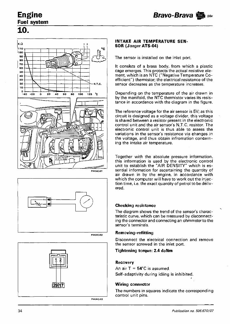
Engine Fuel system
Bravo-Brava 1 0 16v
10. INTAKE AIR TEMPERATURE SOR (Jaeger ATS-04)
SEN-
The sensor is installed on the inlet port.
It consists of a brass body, from which a plastic cage emerges. This protects the actual resistive element, which is an NTC ("Negative Temperature Coefficient") thermistor; the electrical resistance of the sensor decreases as the temperature increases.
Depending on the temperature of the air drawn in by the manifold, the NTC thermistor varies its resistance in accordance with the diagram in the figure.
The reference voltage for the air sensor is 5V; as this circuit is designed as a voltage divider, this voltage is shared between a resistor present in the electronic control unit and the air sensor's N.T.C. resistor. The electronic control unit is thus able to assess the variations in the sensor's resistance via changes in the voltage, and thus obtain infromation concerning the intake air temperature.
Together with the absolute pressure information, this information is used by the electronic control unit to establish the "AIR DENSITY" which is essential information for ascertaining the quantity of air drawn in by the engine, in accordance with which the computer will have to work out the injection time, i.e. the exact quantity of petrol to be delivered.
Checking resistance The diagram shows the trend of the sensor's characteristic curve, which can be measured by disconnecting the connector and connecting an ohmmeter to the sensor's terminals.
Removing-refitting Disconnect the electrical connection and remove the sensor screwed in the inlet port.
Tightening torque: 2.4 daNm
Recovery An air T = 54°C is assumed. Self-adaptivity during idling is inhibited. Wiring connector The numbers in squares indicate the corresponding control unit pins.
34 Publication no. 506.670/07

Bravo-Brava 1 0 16v Engine Fuel system
10. ENGINE IDLE SPEED ACTUATOR (step motor) (WEBER B02)
1. Bearing 2. Lead screw 3. Coils 4. Magnets
5. Screw 6. Anti-rotation
grooves 7. Plunger
The actuator is fitted to the butterfly valve case and consists of: - An electric step motor with two windings in the stator
and a rotor that contains a certain number of permanent magnet pairs.
- A worm and screw reduction unit that converts rotatory motion into linear motion.
In order to idle, i.e. with throttle (4) fully closed, the engine needs a certain amount of air (Qo) and fuel to overcome internal friction and maintain rpm levels.
To the quantity of air Qo that leaks through the closed butterfly valve (4) during idling, an additional quantity of air Q must be added to allow the engine to maintain rpm levels constant, particularly during warm up and when electrical users or external loads are activated (air conditioner, automatic transmission, etc).
To achieve this result, the system uses a step motor (1) fastened to butterfly valve case (5) controlled by ECU (6) which moves a rod fitted with a plunger (3) during operation. This alters the cross-section of by-pass duct (2) and thus the amount of air (Qo + Q) taken in by the engine.
In order to govern this type of action, the ECU uses angular engine speed and coolant temperature input from the relevant sensors.
m
3 5
+ 1 2 V o-
r , 2 1
® C , J
2 0
L D A j
40
9 L, B (34-© i —*— ' i
Copyright Fiat Auto 35

Engine Bravo-Brava @ | i 6 v
Fuel system 10.
The electric step motor features extremely high accuracy and resolution (about 20 rpm). Pulses sent from the ECU to the engine are converted from rotary motion into straight-line motion (about 0.04 mm/step) through a worm and screw mechanism. This operates a plunger which in turn moves to alter the by-pass duct cross-section.
The constant idle air flow Qo arises as a result of leakage through the butterfly valve. This is regulated during production and protected by a cap. Maximum flow Q2 arises when the plunger is fully retracted (about 200 steps corresponding to 8 mm). Between these two levels, air flow follows the graph shown alongside.
P4A36CJ01
Motor strategy The number of working steps is dependent upon engine conditions: - Start-up stage
When the key is inserted, the ECU controls step motor position according to engine coolant temperature and battery voltage.
- Warming-up stage Rpm levels are corrected according to engine coolan temperature.
- With engine warm: Idle control is dependent on a signal from the rpm sensor. When external users are activated, the ECU governs sustained idle.
- Over-run: The ECU recognises over-run status frofiTthe throttle potentiometer position. It controls step motor position by means of the idle flow law (DASH - POT laws). In other words, it slows the return of pluger (3) to its seat so that a quantity of air by-passing hole (2) reaches the engine and reduces levels of pollutants in the exhaust gas.
Recovery Actuator operation disenabled and self-adaption of idling fuel mixture level blocked. Removing-refitting engine idle control actuator (step motor) - disconnect battery negative terminal; - unscrew both retaining screws and withdraw the actuator; - check condition of thoroid seal and remove any impurities from the case seat;
- refit the actuator, checking that the plunger fits easily without forcing. To do this, fit the actuator and replace screws but do not tighten. Operate the step motor using a Fiat-Lancia/Tester until it has moved through its entire travel. Tighten screws only after checking plunger is correctly aligned in its seat and electrical connector is positioned correctly.
NOTE It is advisable to leave the battery negative terminal disconnected for about 20 minutes. Provided the abo ve procedure is carried out as described, the ECU will position the idle speed actuator correctly the first time the engine is started up. Fit new step motor retaining screws whenever they are loosened or removed because the threads are covered with a light layer of loctyte, which guaranteeds a seal only once.
Tightening torque of step motor screws 0.36 - 0.44 da Nm.
Air flow graph step no.
36 Publication no. 506.670

Bravo-Brava 1 0 16v Engine Fuel system
10.
a
mV
4750
2500
250 0 127,5 475,5 787,5 mmHg
Wiring connector
The numbers in boxes indicate the corresponding control unit pins
ABSOLUTE PRESSURE SENSOR WEBER PRT 03
The sensitive element is enclosed within a plastic container (1) and consists of a Wheat-stone sridge screen printed to a very fine circular ceramic plate (diaphragm) fitted to the underside of a ring mount.
The diaphragm separates two chambers: a vacuum is set up in the bottom sealed chamber while the top chamber communicates with the intake manifold indirectly through a rubber pipe (3).
When the engine is off, the diaphragm bends according to atmospheric pressure level. Exact information on altitude is therefore provided when the key is inserted.
When running, the engine sets up a vacuum that gives rise to a mechanical effect on the sensor diaphragm, which bends to alter the resistance level.
Because the electrical supply is maintained constant (5 V) by the control unit, when the resistance is altered, the output voltage changes in proportion to the vacuum in the intake manifold.
Recovery
The pressure is calculated according to throttle angle and rpm level. If the butterfly valve position sensor is faulty, a fixed calibration value is assigned. Mixture self-adaption is inhibited. Lambda probe test is inhibited.
A B C
34 17114
Copyright Fiat Auto 3 7

Engine Fuel system
Bravo-Brava 1 0 16v
10. COOLANT TEMPERATURE SENSOR (Jeager 401930.01)
The sensor is fitted to the thermostat case. It consists of a brass case, which protects the actual resistance element: an NIC thermistor (standing for Negative Temperature Coefficient because sensor electrical resistance decreases in inverse proportion to temperature).
The reference voltage is 5V; since this circuit is designed as a voltage divider, the voltage is distributed between a resistance present in the ECU and the sensor N.T.C. resistance. The ECU is therefore able at any moment to assess sensor resistance changes through voltage changes and thus obtain information on intake air temperature.
Recovery The last reading is adopted. If the temperature does not correspond to steady state levels, this is gradually increased with time following start-up and corrected on the basis of intake air temperature.
Mixture concentration self-adaption is inhibited.
Idle self-adaption is inhibited.
Checking resistance The graph plots sensor resistance values. These may be measured by disconnecting the connector and connecting an ohmmeter to the sensor terminals.
Removing-refitting Disconnect electrical connection and remove the sensor
Before refitting apply MR/B anaerobic sealant to the tapered threads.
Tightening torque 2.4 daNm.
Wiring connector The numbers in boxes indicate the corresponding control unit pins
38 Publication no. 506.670

Bravo-Brava 1 0 * * Engine Fuel system
10. ELECTRIC FUEL PUMP (Walbro-Marwal MSS071)
The pump is housed inside the fuel tank in a holder, together with the fuel level indicator. It is fitted with a mesh filter on the pump intake.
The pump is volumetric type and designed to work with unleaded fuel.The rotor is turned by an electric d.c. motor supplied at battery voltage directly through the dual relay, controlled in turn by the E C U .
The motor is submerged in the fuel in order to clean and cool the brushes and commutator.
The pump is fitted with a pressure relief valve, which short-circuits delivery to intake if inlet circuit pressure exceeds 5 bar. This prevents the electric motor overheating.
A check valve fitted in the delivery line prevents the entire fuel circuit emptying when the pump is not working.
Rated pump output varies according to angular rotor speed and hence supply voltage: it is about 140 l/h at a voltage of 12 V. „
1. Electrical connectors
2. Delivery port
3. Inlet port
4. Pressure relief valve
5. Check valve
Copyright Fiat Auto 39

Engine Fuel system
Bravo-Brava 10 16v
10. Removing-refitting electric fuel pump
The pump is located in the tank: proceed as follows to remove:
Undo retaining buttons indicated using tool 1878077000.
Lift load compartment mat.
Remove dust cover.
Disconnect electrical connections from pump and from fuel level sending unit.
Disconnect fuel lines (inlet, outlet and breather).
Unscrew lock-ring retaining pump to tank using tool 1860893000 and a box wrench.
Remove fuel pump assembly.
When refitting, electrical connections and fuel lines cannot be fitted the wrong way round because the respective terminals are of different diameter.
< t > Components of fuel pump assembly
1. Fuel level gauge
2. Retaining plate
3. Electric pump
4. Reservoir with mesh prefilter
40 Publication no. 506.670

Bravo-Brava iBt 16v Engine Fuel system
10. < i >
FUEL FILTER (Bosch A 450.024.262)
The filter is inserted in the fuel delivery pipe; it consists of a steel plate casing and an internal polyurethane mounting on which an element with high-filtration capacity is wound.
NOTE On the outer casing, there is an arrow which indicates the direction of fuel flow and so correct assembly.
1. Fuel inlet
2. Arrow position
3. Fuel outlet
Removi ng - ref itti ng
To remove the fuel filter, proceed as follows:
Raise the vehicle.
Undo the bolts indicated and remove the protective cover.
Disconnect the fuel inlet and outlet quick-fit connectors from the filter, collecting in a suitable container the fuel which leaks during the operation.
Undo the bolt and remove the filter.
A The fuel filter must be replaced every 40000 km. After replacing the filter, start the engine and check that there are no fuel leaks from the connections.
Copyright Fiat Auto VI-96 - Update 4 1

Engine Fuel system
Bravo-Brava 10 16v
10. FUEL MANIFOLD (CB 104)
The fuel manifold is secured to the inside of the inlet manifold, and its function is to send fuel to the fuel injectors.
The fuel manifold consists of an aluminium casting and it incorporates the seats for the fuel injectors and pressure regulator.
The fuel inlet comprises an attachment with tapered sealing screw.
The fuel is recirculated by means of a pipe contained in the manifold and connected at one end to the regulator, and at the other end to the external fuel return pipe to the tank.
v///>A/////tyy/j(
1. Fuel manifold
2. Fuel injectors
3. Pressure regulator
4. Fuel inlet connection
5. Connection for fuel return to tank 6. Diaphragm
7. Backflow valve
8. Adjustment spring
9. Vacuum connection
1 0 . Fuel inlet
1 1 . Fuel return
42 Publication no. 506.670/07

Bravo-Brava 10** Engine Fuel system
10. FUEL PRESSURE REGULATOR (RPM 40) This differential diaphragm device is set to a pressure of 3.00 ± 0.05 bar in the factory. Pressurised fuel from the pump exercises thrust on reflux valve (7) countered by calibrated spring (8). When pressure setting is exceeded, reflux valve opens and excess fuel returns to the tank in order to stabilise pressure in the circuit. The vacuum in the intake manifold (acting also on injector nozzle ) acts on regulator diaphragm through intake (9) in order to reduce the load on the calibration spring. The pressure differential between the fuel and the injector's surroundings (intake manifold) is therefore maintained constant under all engine service conditions. The injector flow (for a given supply voltage) thus depends solely on injection time established by the ECU.
NOTE 77?e ECU assumes pressure as a fixed parameter. The regulator should never therefore be tampered with; otherwise the mixture concentration specified for the engine will be altered.
CARBON FILTER AND FUEL VAPOUR CUT-OFF VALVE
These components form part of the fuel evaporation control and vapour recovery system. They are located in the right wheel arch compartment and can be reached by removing the rear part of the right front wheel arch compartment trim.
1. Fuel vapour cut-off solenoid
2. Carbon filter
Carbon filter This consists of carbon granules (4) that trap fuel vapour entering intake (5). Warm flushing air enters intake (1), through paper filter (3) and flows over the carbon granules to remove fuel vapours and carry them toward the outlet (2) and then on toward the cut-off valve. Air entering through intake (5) may also be pulled back by a vacuum in the tank, when it serves to ventilate the tank. Partition (6) ensures that the flushing air flows over all the carbon granules and promotes the release of fuel vapour toward the inlet manifold. Two springs (7) allow the mass of granules to expand when the pressure increases.
P4A43CJ02
Copyright Fiat Auto 43

Engine Bravo-Brava I0i6v Fuel system 10. Fuel vapour cut-off solenoid (Siemens EC1) The function of this valve is to control the quantity of fuel taken up by the active carbon filter and directed to the intake manifold (via the injection-ignition control unit).
The valve is closed when de-activated to prevent fuel vapours enriching the mixture excessively.
The injection-ignition control unit controls operation as follows:
- during start-up, the solenoid remains closed to prevent fuel vapour from enriching the mixture excessively. This condition persists until the coolant temperature reaches a pre-established threshold.
- with engine warm, the ECU sends the solenoid a square wave signal, which modulates opening in accordance with the signal empty/full pattern. In this way, the ECU controls the quantity of fuel vapour sent to the intake to prevent significant changes in mixture concentration.
Under the service conditions listed below: - throttle in idle position - speed less than 1500 rpm - intake manifold pressure less than a limit setting computed by
the ECU according to rpm level solenoid activation is inhibited to maintain the unit closed in order to improve engine operation.
Longitudinal section through fuel vapour cut-off valve
1. Valve core. 2. Reaction spring. 3. Magnetic winding. 4. Pipe connected to air intake manifold 5. Pipe connected to active carbon filter.
P4A44CJ02
Wiring connector
The numbers in boxes indicate the corresponding control unit pins
Recovery
Mixture self-adaption is inhibited.
Mixture concentration test is inhibited.
Lambda probe test is inhibited.
44 Publication no. 506.670

Bravo-Brava 10 Engine Fuel system
10. MULTIFUNCTION VALVE (SIRIO 0175.00) This valve performs the following functions: - prevents fuel flowing out when tank is over-filled or in case the vehicle overturns in an accident;
- vents fuel vapours from tank to the active carbon trap filter; - ventilates the tank if a vacuum builds up inside. This valve consists of: a float (2); a heavy ball (3); a plate (4), pushed against valve case of spring (5) and plate (8), pushed against plate (4) of spring (9). Multifunctional valve operation may be summarised as follows and depends on fuel tank level: a. if the tank is full float (2) blocks hole (1) to prevent liquid fuel from reaching active carbon filter and
hence damage to the filter; b. the tank fuel level drops, float (2) is lowered and rests upon ball (3) to open hole (1). When the pres
sure exercised by fuel vapours on plate (4) overcomes load of spring (5), a ring opening between plate and valve case opens to allow fuel vapours to emerge from the duct (6) and reach the active carbon filter.
P4A45CJ01
c. if the drop in tank fuel level is sufficient to set up a vacuum, this acts on plate (8) and overcomes load of spring (9) so that this moves down to allow tank ventilation through hole (7).
d. if the vehicle overturns, however full the tank, the weight of ball (3) acts on float (2) to push the float against hole (1) and prevent a dangerous flow of fuel to the intake manifold with the attendant risk of the vehicle catching fire.
P4A45CJ03 P4A45AJ04
Copyright Fiat Auto 45

Engine Fuel system
Bravo-Brava 10 16v
10. VEHICLE SPEED SENSOR
SWF B451 BORLETTI TGK SO.GE.MI.
The sensor is located on the differential output, near the left half-axle joint. It sends information on vehicle speed to the control unit: the signal is also used to operate the speedometer.
The sensor operates on the principle of the Hall effect (see section on "engine timing sensor") and transmits 16 pulses/revolution. Vehicle speed can therefore be calculated from pulse frequency.
Removing - refitting
Disconnect electrical connection and remove the sensor.
Tightening torque 0.8 daNm
Wiring diagram
SAFETY AND VENTILATION VALVE
This valve is located in the fuel filler cap and performs the following functions according to the pressure level in the tank:
When the pressure inside the tank exceeds 0.13 - 0.18 bar, excess fuel vapours are vented to the outside (pressure-relief function).
If, on the other hand, a vacuum builds up inside the tank, equivalent to 0.020 - 0.030 bar, air is taken into the tank (ventilation function).
46 Publication no. 506.670

Bravo-Brava 10 16v Engine Fuel system
10. I N J E C T O R S (WEBER IWP 001)
The twin jet injectors are used specifically on engines with four valves per cylinder because they allow the jets to be directed against the two intake valves.
The fuel jet leaves the injector nozzle with a pressure differential of 3 bars and nebulises immediately to form two cones.
Injector control is «sequential, staged», i.e all four injectors are controlled in accordance with the cylinder intake sequence. The supply to each cylinder may begin during the expansion stage up to a time when intake has already begun.
The fuel manifold presses against the injectors to fasten them into the seats on the intake ducts. They are also anchored to the fuel manifold by means of «safety clips». Two rubber rings (10) and (11) ensure a seal to the intake duct and fuel manifold. The injectors are top-feed type and supplied with fuel from the rear of the case, which houses coil (5) connected to electrical connector (9).
Wiring connector
NOTE The numbers in boxes indicate ECU pin no. in order of cylinder number.
Checking resistance
P4A47CJ03
Injector resistance may be measured by disconnecting the connector and connecting an ohmmeter as shown in the figure. Resistance value 16.2 ohm
Copyright Fiat Auto 47

Engine Fuel system
Bravo-Brava 10 16v
10. INERTIA S A F E T Y SWITCH
The vehicle is equipped with an inertia switch located inside the passenger compartment beneath the driver's seat.
This sensor reduces the possibility of fire (caused by fuel emerging from the injection system) by de-activating the fuel feed pump.
The switch consists of a steel ball fitted inside a tapered housing. It is held in position through the attractive force of an permanent magnet. The ball is released from the magnetic force in the case of violent impact, when it opens the normally closed (NC) electrical circuit to cut off the fuel pump earth connection and thus the fuel supply to the injection system.
To restore the pump earth connection, push the seat back and press the switch until it clicks on.
Removing-refitting 1. Move driver's seat back fully, unscrew the
bolts indicated and remove the plastic protection.
2. Unscrew the bolts indicated, disconnect electrical connection and remove the switch.
After even an apparently light collision, if a smell of petrol is noted or fuel leaks are seen, do not activate the switch again until the fault has been found and corrected in order to avoid the risk of fire.
Inertia switch components
1. Inertia switch assembly 2. Sheath 3. Button 4. Upper end 5. Fitting end 6. Permanent magnet 7. Permanent magnet seat 8. Steel ball
C = Common terminal N.C. Normally closed N.A. Normally open
48 Publication no. 506.670

Bravo-Brava 10 16v Engine Fuel system
10. IGNITION COILS (Marelli Bae 920A)
The coils are fastened by means of a bracket to the camshaft covers and are closed magnetic loop type. They are formed from a layered pack, whose central core (broken by a narrow gap) carries both windings.
The windings are placed in a moulded plastic container embedded in epoxy resin, which gives them exceptional dielectric properties. Because the primary winding is so close to the magnetic core, little magnetic flux is lost and coupling with the secondary winding is maximised.
1. HT socket for cylinder no. 1 spark plug 2. HT socket for cylinder no. 2 spark plug 3. HT socket for cylinder no. 3 spark plug 4. HT socket for cylinder no. 4 spark plug 5. LT socket for ECU connection 6. Primary circuit 7. Gap 8. Secondary circuit
+ 30
LLPJJLSLSUL
pnmnnnr
6
® ©
37
UUL2J1APJU
Tnnnnnr r
© ® ® ®
Wiring connector
NOTE The numbers in boxes indicate the corresponding control unit pins.
Copyright Fiat Auto 4 9

Engine Fuel system
Bravo-Brava 10 16v
10. Checking winding resistance Primary circuit (A cylinders 2-3, B cylinders 1-4) Bring the probes of an ohmmeter into contact with the postive strip (central pin) and the negative strip (pin 1 for circuit A and pin 2 for circuit B). The primary circuit resistance reading on the guage should be between 0.55 and 0.61 ohm at 23 °C.
Secondary circuit (C cylinders 1 -4, D cylinders 2-3) Bring the probes of an ohmmeter into contact between the two high tension outlet terminals. The secondary winding resistance reading on the gauge must be between 8645 and 9555 ohm at 23 °C. Recovery Inhibition of injectors for cylinders in which ingnition is not taking place. Open-loop concentration control
Current command is de-activated when battery d.c. is applied in order to try again later. If circuit is broken, or GND under d .c , charge time assumed to be dependent upon battery voltage.
Removing refitting
1. Disconnect HT leads from spark plugs. 2. Disconnect electrical connections from
the coils and the coolant temperature sensor; unscrew the nuts indicated and remove the coil/HT lead/support bracket assembly.
Disconnect the mount bracket and leads from the coils.
P4AS0CJ03
50 Publication no. 506.670

Bravo-Brava 10 16v Engine Fuel system
10. DUAL RELAY (NDRS 240103)
9 101111 12 131114 15"
DC
1 2 3 4 1 | 5 6 7 8
7 13 8 5 4 0 n o
©u
K1
D2>
D3
12 14
9 10
D2i_r D1 - £ 4 -
1 1 1 0 2 3 9 1 15 8 7 14 1 2 1 3 6 5 4
8 r—KSA>H
U
{204
J 11
13
521
24
38
1. Battery 2. Ignition coils 3. Lambda probe 4. Injectors 5. Electronic control unit 6. Ignition switch 7. 20A system fuse
8. 5A control unit fuse 9. Dual relay (A-Control unit B-Electric fuel
pump) 10. Inertia safety switch 11. Electric fuel pump 12. Fuel vapour cut-off solenoid
Copyright Fiat Auto 51

Engine Bravo-Brava l&iiev Fuel system 10. A dual relay specifically for automotive applications ensures the battery voltage reaches the system. This electrical device consists of a single container containing two special normally open relays whose task is to supply the electronic control unit (section A, control unit supply) and main injection-ignition power circuits (pump, coils etc.) (section B) .
When ignition key is in MAR position "Services 15/54", excitation winding of relay (9) on pin 12 and ECU on pin 13 are activated.
As soon as ECU (5) receives voltage at pin 13 through pin 52 (internal earth), it enables closure of power contacts of relay A (ECU POWER SUPPLY section) to ensure the battary is supplied at pin 35 through fuse (8); it then enables closure of power contacts of relay B in order to earth pin 7 and ensure a power supply to pump (11) and the other sensors and actuators making up the injection system.
The fuel pump must be activated before starting up the engine to ensure that the fuel system is already under a pressure of 3 ± 0.5 bar.lf starting does not not take place with the ignition key in MAR position, the electronic control unit (5) deactivates section of relay (9) pin 7 (pump-components) and automatically stops the pump (11). Timed enablement lasts about 10 sec.
For safety reasons, the ECU (5) activates a control strategy for pump (11) based on engine rpm. In practice, the ECU (5) deactivates section of relay (9) pin 7 in order to cut off supply to the pump (11) when engine rpm drops below a minimum memorised threshold, if the engine stalls with the ignition on or if the start-up code is not recognised by the Fiat C O D E system.
When the ignition key is returned to STOP position, the electronic control unit maintains section A of the dual relay excited for about 90 seconds before cutting off its power supply (time taken to transfer data from RAM STAND-BY memory to the EEPROM.
NOTE Diodes D1 and D2 reduce voltage surges in the respective re/ays. Diode D3 acts against the voltage from the low alternator charge warning light.
Removing-refitting
The dual relay is fitted on a bracket against the rear wall of the engine bay. Proceed as follows to remove-refit:
Remove the protective cover. Disconnect electrical connection and remove the dual relay.
P4A52CJ01
52 Publication no. 506.670
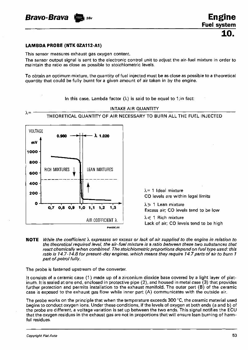
Bravo-Brava 10 16v Engine Fuel system
10. LAMBDA PROBE (NTK 0ZA112-A1)
This sensor measures exhaust gas oxygen content. The sensor output signal is sent to the electronic control unit to adjust the air-fuel mixture in order to maintain the ratio as close as possible to stoichiometric levels.
To obtain an optimum mixture, the quantity of fuel injected must be as close as possible to a theoretical quantity that could be fully burnt for a given amount of air taken in by the engine.
In this case, Lambda factor (X) is said to be equal to 1;in fact:
INTAKE AIR QUANTITY
THEORETICAL QUANTITY OF AIR NECESSARY TO BURN ALL THE FUEL INJECTED
VOLTAGE
mV
1 0 0 0 ¬
8 0 0
6 0 0
4 0 0
2 0 0 - I
0.980
RICH MIXTURES
X 1.020
LEAN MIXTURES
t 1 I I
0,7 0 , 8 0 ,9 1,0 1,1 1,2 1,3
AIR COEFFICIENT X
X= 1 Ideal mixture CO levels are within legal limits
A, 5= 1 Lean mixture Excess air; CO levels tend to be low
1 Rich mixture Lack of air; CO levels tend to be high
NOTE While the coefficient A, expresses an excess or lack of air supplied to the engine in relation to the theoretical required level, the air-fuel mixture is a ratio between these two substances that react chemically when combined. The stoichiometric proportions depend on fuel type used: this ratio is 14.7-14.8 for present-day engines, which means they require 14.7 parts of air to burn 1 part of petrol fully.
The probe is fastened upstream of the converter.
It consists of a ceramic case (1) made up of a zirconium dioxide base covered by a light layer of platinum. It is sealed at one end, enclosed in protective pipe (2), and housed in metal case (3) that provides further protection and permits installation to the exhaust manifold. The outer part (B) of the ceramic case is exposed to the exhaust gas flow while inner part (A) communicates with the outside air.
The probe works on the principle that when the temperature exceeds 300 °C, the ceramic material used begins to conduct oxygen ions. Under these conditions, if the levels of oxygen at both ends (a and b) of the probe are different, a voltage variation is set up between the two ends. This signal notifies the ECU that the oxygen residues in the exhaust gas are not in proportions that will ensure lean burning of harmful residues.
Copyright Fiat Auto 53

Engine Fuel system
Bravo-Brava 10 16v
10. a. Electrode (+) in con
tact with outside air
b. Electrode (-) in contact with exhaust gas
1. Ceramic case 2. Protective pipe 3. Metal case 4. Electrical resistant
When the probe supplies a low voltage level (less than 200 mV) the ECU recognises that the mixture is lean (lambda » 1) and takes steps to increase the amount of fuel injected. When the probe supplies a high voltage level (greater than 800 mV) the control unti recognises that the mixture is rich (lambda « 1 ) and decreases the quantity of fuel injected.
The lambda probe therefore alters injection times to ensure that the engine operates with a lambda factor continually fluctuating between 0.980 and 1.020.
Below 300 °C the ceramic material is not active and the probe does not send usable signals. A special circuit in the control unit blocks loop mixture regulation while the probe is warming up.
To ensure service temperature is reached quickly, the probe is equipped with electrical resistance (4) supplied by the battery
The probe may be swiftly put out of service by even slight traces of lead in the fuel. Operation should be checked at 45,000 and 90,000 km in accordance with the programmed maintenance plan.
Checking resistance
The heater and probe resistance may be measured by disconnecting the connector and connecting an ohmmeter as indicated in the figure.
Heater resistance (A) = 4.3 - 4.7 ohm
Probe resistance (B) = 5000 ohm (max)
Recovery
Lambda data are ignored (open loop).
Wiring connector The numbers in boxes indicate the corresponding control unit pins.
54 Publication no 506.670

Bravo-Brava 10 16v Engine Fuel system
" @ 1 1
o
1 .
10. REMOVING - REFITTING LAMBDA PROBE - Position vehicle on lift
- Disconnect battery negative lead
- Disconnect electrical connection located against the rear wall of the engine bay and protected by a cover.
Remove the lambda probe from its seat on the exhaust pipe.
When refitting, spread the threaded part with ANT/SEIZE MATER I -A-BORON NITRIDE N.G.K. grease from SPARK PLUG CO-LTD.
Tightening torque 3.5 - 4.5 daNm
Copyright Fiat Auto 55

Engine Bravo-Brava 10** Fuel system 10. CHECKS, ADJUSTMENTS AND REPAIRS TO I.A.W. INJECTION-IGNITION SYSTEM.
A OBSERVE THE FOLLOWING PRECAUTIONS WHEN WORKING ON VEHICLES WITH I AW INJECTION-IGNITION SYSTEMS: - never start the engine when the electrical terminals are poorly connected or loose on the battery
poles; - never use a quick battery charger to start the engine; - never disconnect the battery from the car circuit with the engine running; - when charging the battery quickly, first disconnect the battery from the vehicle circuit; - if the vehicle is placed in a drying oven after painting at a temperature of more than 80° C, first re
move the injection/ignition ECU; - never connect or disconnect the ECU multiple connector with the ignition key in MARC/A posi
tion; - a/ways disconnect battery negative lead before carrying out electrical we/ding on vehicle.
Note that the memory of this system is active at all times (memory on stand-by), and contains all learnt self-adaptive parameters. Because all this information would be lost if the battery were disconnected, this operation should only be carried out when absolutely essential.
ADJUSTING THROTTLE CABLE
The accelerator cable is adjusted by moving clip (3) along the grooves on bush (2).
Position the clip so that head (1) of the accelerator cable fits freely into the slot without altering idle speed.
REMOVING-REFITTING FUEL MANIFOLD TOGETHER WITH INJECTORS AND PRESSURE REGULATOR
Disconnect the first section of the oil dipstick mount, disconnect the oil filler pipe, disconnect the injector lead coupling and the pipe connecting the regulator to the vacuum point.
P4A56CJ02
56 Publication no. 506.670

Bravo-Brava 10 16v Engine Fuel system
10.
1. Unscrew the bolts fastening the fuel supply manifold.
2. Unscrew the bolts fastening both sections of the intake manifold together.
3. Unscrew screws fastening the second section of the intake manifold to the engine block and remove.
4. Disconnect the fuel lines and remove the manifold together with regulator and injectors.
Copyright Fiat Auto 57

Engine Fuel system 10. CHECKING F U E L SUPPLY C I R C U I T
Bravo-Brava 10 16v
Test 1
Testing fuel regulation pressure
- Disconnect fuel delivery line to manifold from arrowed fitting.
- Interpose pressure gauge 1895890000 between the disconnected pipe end and the fuel manifold with cocks (A) and (B) open.
- Activate fuel pump with engine off.
P4A58CJ01
The last operation is carried out by selecting "fuel pump" test on a Fiat/Lancia tester. Under these conditions, the pressure gauge reading should stabilise at 3.0 bar. If pressure is insufficient, carry out the test 2.
Test 2
Testing maximum fuel feed pressure (or pump efficiency)
Same connections as previous test.
- Close fuel cock lever (A);
- operate the pump with the engine off, as described previously: pressure should not exceed 7 bar (pump pressure relief valve setting). Otherwise, replace the pump because it is defective.
P4A5SCJ02
58 Publication no. 506.670

Bravo-Brava i0 16v Engine Fuel system
10. If pressure measured in test 1 (see previous page) exceeds 3 bars proceed as follows: - disconnect fuel return pipe (at point
(1) for connection to rigid fuel return line to pump) and place in a container suitable for collecting the fuel.
- open cocks A and B;
- operate the fuel pump with engine off as described on previous page, then take pressure reading off pressure gauge: a. if it reaches 3 bars replace the fuel re
turn pipe to the tank because it is blocked or kinked;
b. if it exceeds 3 bars replace the pressure regulator because it is defective.
Test 3 Checking injector seal To check for drips from the injectors, connect as described in first test (regulation pressure check) and then operate the pump with the engine off. When the regulation pressure is reached, close control lever B and simultaneously constrict fuel return line to tank; use pliers for this purpose and avoid damaging the pipe.
This operation is necessary to discriminate between true loss from the injectors and a faulty seal on the fuel pressure regulator runout valve.
Then: - turn off the pump;
- see whether pressure remains constant for 60 seconds after stabilising (i.e. dropping slightly).
If it does not, one or more injectors or a fitting are leaking. - In this case, disconnect the fuel manifold from the intake manifold and keep the pressure gauge con
nected. - Repeat the previous test but leave the pressure gauge cock open. - After supplying the pump with the engine off, look to see whether any of the injectors or connection
sections are dripping. Replace any dripping injectors and/or repair the defective seal in the leaking joint.
P4A59CJ02
Copyright Fiat Auto 5 9

Engine Fuel system
Bravo-Brava 10 16v
10. CHECKING ENGINE IDLE S P E E D If engine speed is not 850 ± 50 rpm, because the injection-ignition system is self-regulating, no adjustment can be carried out. It is therefore necessary to check that the accelerator linkage is properly adjusted and then search for the fault through full diagnosis using a Fiat/Lancia Tester.
CHECKING L E V E L S OF POLLUTING EMISS IONS The IAW -1 AF.13 system is self-adaptive and thus constantly monitors idle speed and CO levels. Therefore there is no need for manual adjustment (adjustment screws are no longer fitted). However, checking exhaust contents downstream of the catalytic converter can provide useful information about the injection-ignition system condition, engine and catalytic converter parameters
Checking CO and HC levels when idling Measure levels of carbon monoxide (CO) and unburnt hydrocarbons (HC) with the catalytic converter hot (300 - 350 °C) (it is advisable to push the car engine on the road for about 5-10 minutes to ensure that the catalytic converter reaches service temperature), Then fit the probe of a suitably calibrated tester to at least 30 cm as indicated in the figure.
If the shape of the exhaust tail pape will not allow the probe to be fully inserted, add an extension pipe designed to ensure a seal in the joint area.
1. Check that CO and HC levels are as specified in the table; 2. If CO level is not as specified, check that:
- Lambda probe is working properly, with the aid of a Fiat/Lancia Tester; - for air leaks in the area surrounding the lambda probe seat - the injection and ignition system (particularly for spark plug wear).
3. If HC level is not as specified, the engine is not properly tuned or the catalytic converter is not efficient.
CO (%) HC (p.p.m.) CO2 (%)
<0.35 <90 ^ 13
Summary table showing emission level tolerances downstream of converter
60 Publication no. 506.670
I
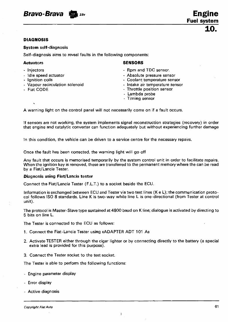
Bravo-Brava 10 16v Engine Fuel system
10. DIAGNOSIS
System self-diagnosis
Self-diagnosis aims to reveal faults in the following components:
Actuators SENSORS
- Injectors - Idle speed actuator - Ignition coils - Vapour recirculation solenoid - Fiat CODE
- Rpm and TDC sensor. - Absolute pressure sensor - Coolant temperature sensor - Intake air temperature sensor - Throttle position sensor - Lambda probe - Timing sensor
A warning light on the control panel will not necessarily come on if a fault occurs.
If sensors are not working, the system implements signal reconstruction strategies (recovery) in order that engine and catalytic converter can function adequately but without experiencing further damage
In this condition, the vehicle can be driven to a service centre for the necessary repairs.
Once the fault has been corrected, the warning light will go off
Any fault that occurs is memorised temporarily by the system control unit in order to facilitate repairs. When the ignition key is removed, these are transferred to the permanent memory where the can be read by a Fiat/Lancia Tester.
Diagnosis using Fiat/Lancia tester
Connect the Fiat/Lancia Tester (F.L.T.) to a socket beside the ECU.
Information is exchanged between ECU and Tester via two test lines (K e L); the communication protocol follows ISO 8 standards. Line K is two-way while line L is one-directional (from Tester at control
The protocol is Master-Slave type sustained at 4800 baud on K line; dialogue is activated by directing to 5 bits on line L.
The Tester is connected to the ECU as follows:
1. Connect the Fiat-Lancia Tester using «ADAPTER ADT 101 A»
2. Activate TESTER either through the cigar lighter or by connecting directly to the battery (a special extra lead is provided for this purpose).
3. Connect the Tester socket to the test socket.
The Tester is able to perform the following functions:
- Engine parameter display
- Error display
- Active diagnosis
unit).
Copyright Fiat Auto 61

Engine Fuel system
10. DISPLAYED PARAMETERS
Engine rpm Injection time Absolute pressure to inlet manifold Air temperature Coolant temperature Throttle opening angle Battery voltage Voltage LAMBDA probe status Engine idle speed actuator Self-adaptability Vehicle speed Mixture level Petrol vapour solenoid Fiat CODE
Bravo-Brava 10 16v
List of errors
RPM sensor Throttle potentiometer Absolute pressure sensor Air temperature sensor Coolant temperature sensor Battery
Lambda probe Injector Ignition coils
Idle speed actuator Fuel vapour solenoid Actuator relays
Control unit
A.C-D.C. A.C-D.C. A.C-D.C. A.C-D.C. A.C-D.C. Power supply > 15.5V Power supply < 5V Status not plausible (probe disconnected or faulty) D.C A:C-D.C. A.C-D.C. No. of subsequent steps A.C-D.C. A.C-D.C. Microprocessor or ECU memory faults are indicated.
Self-adaptive parameters
Timing sensor Speed sensor Signal framework
Mixture level
Fiat CODE
Indication displayed when ECU self-adaptive limits reached. This indication means that engine conditions are much too far from specified levels and mechanical causes should also be investigated.
A.C-D.C. Signal absent Tooth count incorrect - Space between two missing teeth not recognised Greater than maximum threshold Lower than minimum threshold Code not recognised or not received
62 Publication no. 506.670

Bravo-Brava 0 16v Engine Index 10.
page page
HITACHI INTEGRATED INJECTION/IGNITION SYSTEM 1 - Diagram showing operation of
HITACHI injection/ignition system 2 - Diagram showing information arriving
at/leaving control unit and sensor/actuators HITACHI injection/ignition system 3
- Location of HITACHI injection/ignition system components in engine compartment 4
SYSTEM MANAGEMENT STRATEGIES 5 - Signal management 7 5 - Injection management 6 - FIAT CODE anti-theft system manage
ment 10 - Ignition management 11 - Engine idle control management 13 - Charcoal filter management 13 - Radiator fan management 14 - Climate control system management 16
DIAGNOSIS 17 J . .. •
RECOVERY STRATEGIES 19
ELECTRICAL/ELECTRONIC CIRCUIT 20 I HITACHI system control unit pin-out 21 ^ HITACHJ system wiring diagram 22 - System relays . 23 - Engine rpnrusensor 24 - Engine timing sensor 25 - Air flow meter 26 - Lambda sensor 27 - Butterfly position sensor 28 - .Engine coolant temperature sensor 28 - Vehicle speed sensor 29 - Detonation sensor 29 - Ignition system 30 - Ignition power module 31 - Ignition coil 31
DIAGRAM SHOWING INLET CIRCUIT 32
INLET CIRCUIT 33 - Butterfly casing 33 - Engine idle speed adjustment
solenoid valve 34
DIAGRAM SHOWING FUEL SUPPLY CIRCUIT 35
FUEL SUPPLY CIRCUIT 35
- Electric fuel pump 36 - Fuel filter . 36 - Inertia safety switch - 37 - Anti-flow single-acting valve 37 - Fuel manifold 38 - Fuel pressure regulator 38 - Injectors 39
EMISSION CONTROL DEVICES 40
- Catalytic silencer 40 - Fuel anti-evaporation system 41 - Crankcase gases recirculation system
(blow-by) 45
TIGHTENI NG TORQUES 46
CHECKS, ADJUSTMENTS AND REPAIR OPERATIONS ON HITACHI MPI SYSTEM 47 - Fuel supply circuit 47 - Fuel circuit pressure checks 50 - Inlet circuit 52 - Electrical circuit 54
CHECKING EMISSION CONCENTRATION 57
CHECKING ENGINE IDLE SPEED 58
CHECKING IGNITION ADVANCE 58
Copyright by Fiat Auto

Bravo-Brava Engine Fuel system
10. HITACHI INTEGRATED INJECTION/IGNITION SYSTEM
Introduction
The H itach i system fitted on the Bravo-Brava with the 1747 i.e. 16v eng i ne belongs to the category of static advance digital electronic ignition systems integrated with multiple phased type intermittent electronic fuel injection systems. This system therefore has only one control unit, one set of wiring and one set of common sensors for both systems. The integrated system can be summarized in the following syb systems:
ELECTRICAL/ELECTRONIC CIRCUIT AIR INTAKE CIRCUIT FUEL SUPPLY CIRCUIT EMISSION CONTROL DEVICES
The system is capable of detecting the following parameters via special sensors: 1. the engine rotation speed; 2. the position of each pair of pistons in relation to TDC for cylinder 1; 3. the engine intake air flow rate; 4. the position and the speed of the variation of the position of the accelerator butterfly; 5. the temperature of the engine coolant; 6. the effective strength of the mixture (through the Lambda sensor signal); 7. the presence of detonation; 8. the speed of the vehicle; 9. the battery voltage;
10. whether the climate control compressor is switched on.
This information, usually of an analogue type, is converted into digital signals by analogue/digital (A/D) converters in order to be able to be used by the control unit. In particular, any engine operating point is detected, moment by moment, by two parameters:
- the engine rotation speed, measured in revolutions per minute (rpm); - the engine load, which is constituted by the quantity of air drawn in by each cylinder.
This quantity is calculated on the basis of the flow rate of the air drawn in and is represented by the parameter TP, measured in milliseconds (ms).
Inside the control unit memory there is a managment programme (software) which comprises a series of strategies, each of which manages a precise system control function. By using the (input) information listed previously, each strategy processes a series of parameters, based on the data maps stored in the control unit memories and then controls the system (output) actuators which are the devices which allow the engine to operate, namely:
1. injectors; 2. ignition coils; 3. solenoid valves implementing various functions; 4. fuel pump; 5. control relays.
NOTE The HITACHI injection/ignition system does not require any adjustment as it is self-regulating and self-adjusting.
NOTE In the diagrams, the numbers indicate the corresponding HITACHI engine control unit pins.
NOTE All the connectors are seen from the side opposite the cable input.
Copyright by Fiat Auto 1

Bravo-Brava 10** Engine Fuel system 10.
DIAGRAM SHOWING OPERATION OF HITACHI INJECTION/IGNITION SYSTEM
P4A02BJ01
1. Cap with safety valve 19. Injector 2. Fuel tank 20. Fuel pressure regulator 3. Electric fuel pump 21. Ignition power module 4. Anti-flow valve 22. Ignition coil 5. Fuel filter 23. Engine timing sensor 6. Battery 24. Radiator fan 7. Ignition switch 25. Engine rpm sensor 8. System relays 26. Detonation sensor 9. Climate control compressor 27. Coolant temperature sensor
10. Inertia switch 28. Charcoal filter solenoid valve 11. Vehicle speed sensor 29. Charcoal filter 12. F/L Tester connector (diagnostic socket) 30. Fiat CODE control unit 13. Rev counter 31. Lambda sensor 14. System failure light 32. Catalytic silencer 15. Air flow meter 33. HITACHI engine control unit 16. Engine idle adjustment solenoid valve 34. Multi-purpose valve 17. Butterfly position sensor 35. Fuel vapour separator 18. Fuel manifold with integrated pressure 36. Float valve
regulator
2 Print no. 506.670

Bravo-Brava 0 16v Engine Fuel system
10. DIAGRAM SHOWING INFORMATION ARRIVING AT/LEAVING CONTROL UNIT AND HITATCH INJECTION/IGNITION SYSTEM SENSORS/ACTUATORS
1. HITACHI engine control unit 2. Radiator fan solenoid valve 3. Radiator fan 4. Speedometer 5. Vehicle speed sensor 6. Air flow meter 7. Engine rpm sensor 8. Coolant temperature sensor 9. Butterfly position sensor
10. Lambda sensor 11. Ignition switch 12. Detonation sensor 13. Engine timing sensor
14. Climate control compressor 15. F/L Tester connector (diagnostic socket) 16. Charcoal filter solenoid valve 17. Engine idle adjustment solenoid valve 18. Rev counter 19. Injectors 20. System relays 21. Electric fuel pump 22. Spark plugs 23. Ignition coils 24. Ignition power module 25. Fiat C O D E control unit
Copyright by Fiat Auto 3

Engine Fuel system
Bravo-Brava 0 16v
10. LOCATION OF HITACHI INJECTION/IGNITION SYSTEM COMPONENTS IN ENGINE COMPARTMENT
1. Ignition coils 2. Injectors 3. Engine timing sensor 4. Coolant temperature sensor 5. Vehicle speed sensor 6. Air flow meter 7. Engine idle speed adjustment solenoid
valve 8. Butterfly position sensor 9. Fuel pressure regulator
10. Engine rpm sensor 11. Detonation sensor 12. Fuel manifold 13. Ignition power module 14. Charcoal filter solenoid valve 15. HITACHI engine control unit 16. Relays 17. Fuses 18. Injection/ignition system earths 19. Lambda sensor
4 Print no. 506.670
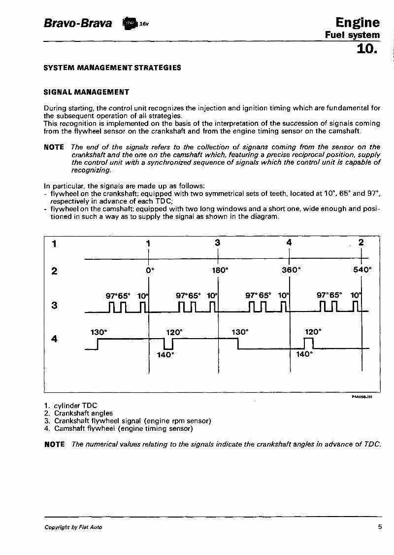
Bravo-Brava ifih 16v Engine Fuel system
10. SYSTEM MANAGEMENT STRATEGIES
SIGNAL MANAGEMENT
During starting, the control unit recognizes the injection and ignition timing which are fundamental for the subsequent operation of all strategies. This recognition is implemented on the basis of the interpretation of the succession of signals coming from the flywheel sensor on the crankshaft and from the engine timing sensor on the camshaft.
NOTE The end of the signals refers to the collection of signans coming from the sensor on the crankshaft and the one on the camshaft which, featuring a precise reciprocal position, supply the control unit with a synchronized sequence of signals which the control unit is capable of recognizing.
In particular, the signals are made up as follows: - flywheel on the crankshaft: equipped with two symmetrical sets of teeth, located at 10°, 65° and 97°,
respectively in advance of each TDC; - flywheel on the camshaft: equipped with two long windows and a short one, wide enough and posi
tioned in such a way as to supply the signal as shown in the diagram.
130°
_ r
97°65° 10'
_rui_n
180°
97°65° 10e
J U L J l 120°
I T 140'
97° 65° 10'
J U L J l 130°
360° 540°
97° 65° 10°
J U L - J L -120°
J ~ L 140*
1. cylinder TDC 2. Crankshaft angles 3. Crankshaft flywheel signal (engine rpm sensor) 4. Camshaft flywheel (engine timing sensor)
NOTE The numerical values relating to the signals indicate the crankshaft angles in advance of TDC.
Copyright by Fiat Auto 5

Engine Bravo-Brava Fuel system 10. INJECTION MANAGEMENT
The injection management strategies have the aim of supplying the engine with the correct quantity of fuel at the desired moment according to the engine operating conditions.
NOTE The presence of the air flow meter makes it possible to directly measure the mass of intake air, making the presence of the intake air temperature sensor superfluous.
The management of the injection consists essentially in the calculation of the injection time, the determining of the injection timing and the subsequent implementation by operaating the injector. The "basic" injection time depends on the characteristics of the injector and corresponds to the quantity of fuel to be injected into each cylinder. The latter, in turn, multiplies the quantity of air drawn in by each cylinder (calculated on the basis of the quantity of intake air and on the engine rotation speed) for the desired mixture strength in relation to the engine operating point. The final injection time is determined through a calculation algorhythm in which the "basic" injection time is corrected by a series of coefficients which take into account the different engine operating conditions which are shown by the various sensors present in the system.
A: "basic" injection time B: corrective coefficients: low engine temperature
high engine temperature starting and post-starting butterfly fully open deceleration acceleration
C: checking mixture strength D: self-adjustment E: cut-off F: intermediate injection time G: extra-pulse H: management not timed by injection
6 Print no. 506.670

Bravo-Brava Engine Fuel system
10. Checking mixture strength
NOTE The following ratio is defined as the mixture ratio and is denoted by the Greek lettercx (a/fa):
quantity of air drawn in by the engine
quantity of fuel injected
The following ratio is defined as the stoichiometric mixture and is denoted by cxst :
theoretical quantity of air to burn all the fuel injected
quantity of fuel injected
The following ratio is defined as the mixture strength andis denoted by the Greek letter X (lambda):
quantity of air drawn in by the engine theoretical quantity of air to burn all the fuel injected
It can easily be deduced that a / ast = X . The stoichiometric ratio depends on the type of fuel: for current unleaded petrols it is around 14.7 -14 .8 which corresponds to a Lambda strength of 1. We talk of a mixture being rich when the quantity of air is lower than the stoichiometric ratio in which case the Lambda < 1: we talk of a mixture being poor (or lean) when the quantity of air is higher than the stoichiometric ratio in which case the Lambda >1,
The strategy has the function of correcting the "basic" injection times so that the mixture strength constantly oscillates at a high frequency between 0.98 and 1.02. The oscillation frequency varies according to the engine load and speed: it is in the order of tens of Hertz.
NOTE iHz-1 oscillation per second
In conditions of: - cut-off, - butterfly opening above 70°, - engine temperature below 25°C, the strategy is disabled.
f Self-adjustment
The control unit is equipped with a self-adjustment function which has the task of memorizing any differences between the basic map and the corrections set by the Lambda sensor which may occur during operation. These differences (due to the ageing of the system and engine components) are memorized permanently, allowing the adaption of the operation of the system to gradual alterations of the engine and the components in relation to the characteristics when new. The strategy is disabled when the charcoal filter solenoid valve is open. If the control unit is replaced it is necessary to carry out a road test which allows the engine to reach operating temperature and the control unit (above all during idling stops) to operate in the self-adjustment mode.
Copyright by Fiat Auto 7

Engine Bravo-Brava 10** Fuel system
10. Starting and post-starting
During starting it is not possible to recognize the engine timing and consequently it is not possible to implement the timed injection. During the first revolutions of the engine an initial simultaneous injection is carried out (also because the considerable fluctuations in the rotation speed do not allow the correct calculation of the injection timing) and subsenquently the injection is the timed type. The "basic" injection time "is increased by a multiplication coefficient for the entire time the engine is driven by the starter motor. After starting has taken place the coefficient is gradually reduced until is disappears within a given time which the lower the engine temperature the longer the time taken.
k
ON
1 OFF k: enrichment coefficient t: time a: decrease depending on the
engine temperature ON : engine driven (crank) OFF : engine started (run)
P4A08BJ01
Operation when cold
In these conditions there is a natural weakening of the mixture as a result of the reduced evaporation and the strong condensation of the fuel on the inner walls of the inlet manifold: in addition, the increased viscosity of the lubrication oil causes an increase in the passive resistance of the engine. The "basic" injection time is corrected by a multiplication coefficient which depends on the temperature and the speed of the engine.
Operation in full load conditions
The strategy is enabled when the butterfly opening exceeds 70°. The "basic" injection time is multiplied by a coefficient (dependent on the engine speed) equal to around 1.1.
8 Print no. 506.670

Bravo-Brava 0 ^ Engine Fuel system
10. Operation during acceleration
During this stage the control unit increases the quantity of fuel supplied. The "basic" injection time is multiplied by a coefficient depending on the temperature of the engine and the speed of the opening of the accelerator butterfly (avearge value 1.2). If the brisk variation in the injection time is calculated when the injector is already closed, the control unit reopens the injector (extra pulse), in order to compensate the mixture strength with increased speed; the subsequent injectors are, on the other hand, increase on the basis of the previously mentioned coefficients.
A: normal injection time B: injector re-opening (extra-pulse) C: injection time including enrichment OFF: engine at stationary speed ON: engine in transition
Operation during deceleration
During this stage a negative transit strategy is implemented to decrease the quantity of fuel supplied: the "basic" injection time is multiplied by a coefficient which depends on the temperature of the engine, the speed and the load conditions at the moment immediately prior to the start of the deceleration.
Operation during cut-off
The cuto-off strategy is implemented when the control unit recognizes the butterfly in the idle position (signal frombutterfly potentiometer) and the engine speed is above 1600 rpm (with the engine warm). The supply to the engine is re-enabled with the recognition of the butterfly in the not closed position or-when the speed goesbelow 1200 rpm (with the engine warm).
Copyright by Fiat Auto 9

Engine Fuel system
Bravo-Brava 0 16v
10. Rotation speed limiter
The strategy restricts the maximum speed which can be reached by the engine enabling the cut-off gradually, as shown in the table. Maximum speed: 6550 rpm
cyl inders
method ^ \ 1 2 3 4
1 cilindro • 2 cilindri • • 3 cilindri • • • 4 cilindri • • • •
Electric fuel pump operation
The electric fuel pump is operated by the engine control unit via a relay. The pump cut out takes place:
- if the engine speed goes below 50 rpm; - after a certain time (about 5 seconds) with the ignition switch in the ON position without the engine
being started up (timed inhibitor); - if the inertia switch has intervened.
Injector operation
The operation of the injectors is the sequential timed type. However, during starting the injectors are operated once in parallel. The timing of the operation of the injectors is variable according to the engine speed.
FIAT CODE ANTI-THEFT SYSTEM MANAGEMENT
The system is equipped with an anti-theft function. This function is achieved thanks to the presence of a special control unit (FIAT CODE) , capable of dialogue with the engine control unit and an electronic key, equipped with a special transmitter for sending a recognition code. Each time the key is turned to the OFF position, the Fiat CODE system completely deactivates the engine control unit. If the key is turned to the ON position, the following operations take place in the order given: 1. the engine control unit (whose memory contains a secret code) sends the FIAT CODE memory a re
quest so that the latter sends the secret code to deactivate the locking of the functions; 2. the Fiat CODE control unit responds by only sending the secret code after having, in turn, received
the recognition code transmitted by the ignition key; 3. the recognition of the secret code allows the de-activation of the locking of the engine control unit
and its normal operation.
NOTE The presence of the FIA T CODE anti-theft system makes it strongly inadvisable, during diagnosis, to proceed with the test using another engine control unit. In effect, in such a case, the Fiat CODE control unit would transfer the (unrecognized) recognition code to the test control unit which would then make it unusable on other vehicles.
10 Print no. 506.670
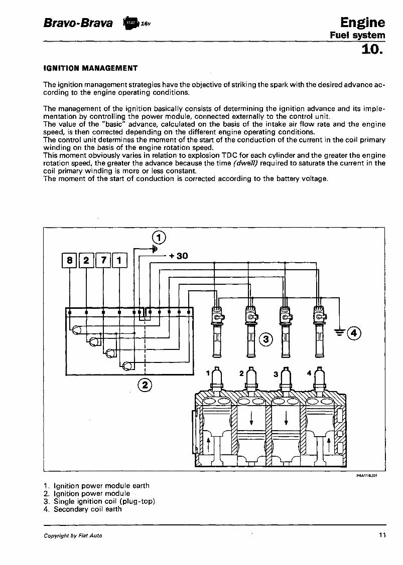
Bravo-Btava 10** Engine Fuel system
10. IGNITION MANAGEMENT
The ignition management strategies have the objective of striking the spark with the desired advance according to the engine operating conditions.
The management of the ignition basically consists of determining the ignition advance and its implementation by controlling the power module, connected externally to the control unit. The value of the "basic" advance, calculated on the basis of the intake air flow rate and the engine speed, is then corrected depending on the different engine operating conditions. The control unit determines the moment of the start of the conduction of the current in the coil primary winding on the basis of the engine rotation speed. This moment obviously varies in relation to explosion TDC for each cylinder and the greater the engine rotation speed, the greater the advance because the time (dwell) required to saturate the current in the coil primary winding is more or less constant. The moment of the start of conduction is corrected according to the battery voltage.
P4A11BJ01
1. Ignition power module earth 2. Ignition power module 3. Single ignition coil (plug-top) 4. Secondary coil earth
Copyright by Fiat Auto 11

Bravo-Brava 10b 16v
Starting
During starting it is not possible to carry out the normal management of the advance because the considerable fluctuations in the rotation speed do not allow the correct calculation of the dwell and the advance. The advance is therefore managed by taking the following as a reference: - for the start of conduction, the tooth at 65°; - for the ignition advance, the tooth at 10°. As a result there is a fixed advance at 10° for the entire time the engine is driven by the starter motor.
Operation when cold
During operation when cold an additional correction of the advance is implemented: the increase in the advance in relation to the one in the memory is inversely proportional to the temperature of the engine.
Engine Fuel system 10.
PMS PMS
97 65 10
a 97 65 10
I I
ON /
ACC
OFF r A a
a: crankshaft flywheel signal A a: fixed ignition advance (10° engine)
ON : activated coil conduction OFF: de-activated coil conduction
Operation during cut-off
The ignition advance is increased at the entry into cut-off: from the moment the supply of fuel is re-enabled the advance is gradually restored to the "base" value.
A a '
— A RPM X . + A RPM
Operation with engine idling
When the engine is idling, the management of the advance is implemented independently of the "basic" advance. The value of the advance during idling, which varies according to the temperature of the coolant (10° with the engine warm) is corrected in accordance with the variation of the speed in relation to the pre-set speed, which also depends on the temperature. In particular, the advance is increased if the speed decreases and is reduced if the speed increases, in order to ensure the stability of the actual speed.
A a: correection of ignition advance during idling +A RPM: the idle speed exceeds the nominal value -A RPM: the idle speed is lower than the nominal value
12 Print no. 506.670

Bravo-Brava filW Engine Fuel system
1 0 7
Checking detonation The strategy has the task of detecting the presence of the phenomenon of detonation, by processing the signal coming from the appropriate sensor. The strategy constantly compares the signal coming from the sensor with a level which, in turn, is constantly updated to take into account the background noise and the ageing of the engine. If the system recognizes the presence of detonation, the strategy reduces the ignition advance, producing a step of 2° up to a maximum of 6°, until the phenomenon disappears. As a result, the advance is gradually restored until the basic value or until the phenomenon arises again. In particular, the advance increases are gradully implemented, whilst the reductions are introduced immediately. During acceleration conditions, the strategy uses a higher level, to take into account the increased engine noise under these circumstances. The strategy is also equipped with a self-adjustment function which permanently memorizes the advance reductions which must be continuously repeated in order to adapt the advance to the different conditions in which the engine finds itself (for example, the use of a low octane rating fuel). The strategy is capable of restoring the advance to the value in the memory if the conditions which have caused the reduction no longer exist.
ENGINE IDLE CONTROL MANAGEMENT The general objective of the strategy is to maintain the engine speed around the memorized value (engine warm: 850 rpm): the position assumed by the actuator depends on theengine speed and conditions and the speed of the vehicle.
Starting stage When the key is inserted the actuator assumes a position which depends on the temperature of the engine and the battery voltage (open-loop position).
Engine started with accelerator pedal released The engine speed varies according to the temperature of the engine and is constantly maintained close to this value modifying the position of the shutter to compensate for any oscillations in the speed. This takes place in particular when external loads are applied (power assisted steering, heated rear windscreen, etc). If the electric fans and the air conditioning are switched on, both of which are managed by the control unit, the strategy manages the advance actuator as appropriate.
Normal opeartion
In these conditions the actuator is in the open-loop position.
During deceleration In deceleration conditions outisde of idling, the control unit operates the position of the actuator through a special curve (dash-pot curve), or it slows down the return of the shutter towards its housing, achieving a reduction in the engine braking effect. CHARCOAL FILTER MANAGEMENT The strategy controls the position of the charcoal filter solenoid valve as follows: - during the starting stage the solenoid valve remains closed, preventing the fuel vapours from enrich
ing the mixture; this condition persists until the engine coolant reaches 25°C; - with the engine at operating temperature, the control unit causes the solenoid valve to operate in du
ty-cycle to control the quantity of fuel vapours sent to the inlet, according to the engine speed and load conditions.
In the following operating conditions: - butterfly in closed position, - speed below 1250 rpm, - engien load TP < 1 ms, the operation of the solenoid valve is disabled, keeping it in the closed position.
Copyright by Fiat Auto 13

Engine Bravo-Brava )0i6v Fuel system 10. RADIATOR FAN MANAGEMENT
The control unit directly controls the operation of the radiator fan depending on the coolant temperature and whether or not there is a climate control system.
NOTE Since the temperature of the engine is measured by the appropriate sensor there is no longer a thermal contact on the radiator.
Version without climate control
There is an electric fan which switches on when the temperature of the coolant exceeds 95°C. It switches off with a hysteris of 2°C around the temperature level.
1. Fuse 2. Fan relay 3. Electric fan
Version with climate control
There is an electric fan with two operating modes: - low speed, - high speed.
1. Fuse 2. High speed relay 3. Low speed relay 4. Electric fan 5. Resistance
14 Print no. 506.670

Bravo-Brava 10** Engine Fuel system
10. Diagram showing operation of electric fan for version with air conditioning
Low speed: it switches on when the temperature of the coolant reaches 95°C. High speed: it switches on when the temperature of the coolant reaches 100°C. The speed of the electric fan also depends on the state of the three stage pressure switch for the climate control system which determines the engagement of the first speed and, with a certain delay, that of the second and the subsequent switching off.
t [ s ]
1. State of the three stage pressure switch 2. High speed operating condition 3. Low speed operating condition 4. Coolant temperature trend 5. Three stage pressure switch attachment/detachment delay
ON: speed/pressure switch activated OFF: speed/pressure switch deactivated
Copyright by Fiat Auto 15

Engine Fuel system
Bravo-Brava 10 16v
10. CLIMATE CONTROL SYSTEM MANAGEMENT
The Hitachi engine control unit is operationally connectedto the climate control system and:
1. receives the request to switch on the compressor from the climate control system control unit via pin 28 and operate the relevant functions (additional air);
2. gives the go ahead to switch on the compressor via pin 113 when the conditions laid down by the strategies are confirmed;
3. receives information concerning the state of the three stage pressure switch from pin 17 and operates the relevant functions (radiator fan operation).
As far as point 1 is concerned, if the engine is idling, the control unit increases the air flow rate which goes from the idle actuator in advance of the switching on of the compressor and viceversa places the actuator in the normal position in delay in relation to the switching off of the compressor. On the other hand, as far as point 2 is concerned, the control unit automatically operates the switching off of the comrpessor:
a) for a time of 6 s (timed switching off): - in butterfly opening conditions of more than 70°, - when the vehicle is accelerating;
b) when the following critical conditions persist: - at coolant temperatures conditions above 114°C, - when the engine idle speed is below 750 rpm.
J b l JUL
1 1 3 *
28*-
1 7 * +15 p
i n n n F i w v w w i rv
J T
1. Compressor 2. Compressor relay 3. Fuse box
4. Battery 5. Climate control unit 6. Three stage pressure switch
16 Print no. 506.670
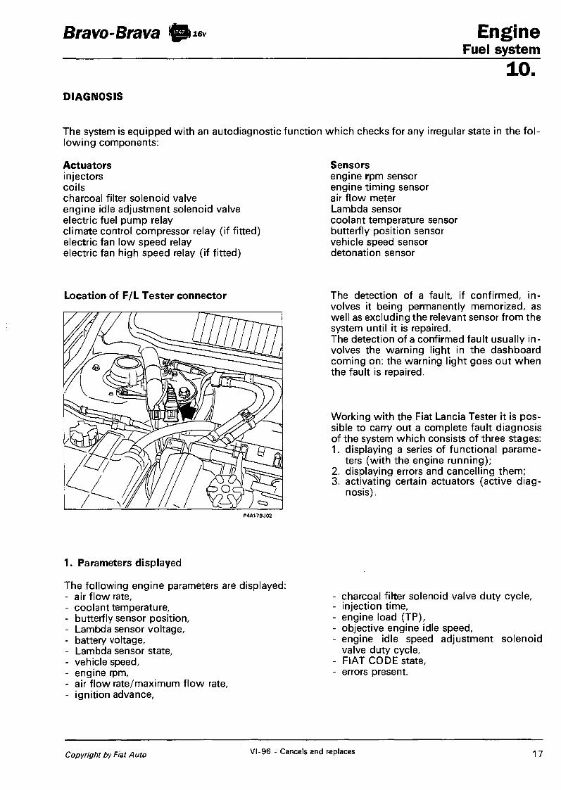
Bravo-Brava Engine Fuel system
10. DIAGNOSIS
The system is equipped with an autodiagnostic function which checks for any irregular state in the following components:
Actuators injectors coils charcoal filter solenoid valve engine idle adjustment solenoid valve electric fuel pump relay climate control compressor relay (if fitted) electric fan low speed relay electric fan high speed relay (if fitted)
Sensors engine rpm sensor engine timing sensor air flow meter Lambda sensor coolant temperature sensor butterfly position sensor vehicle speed sensor detonation sensor
Location of F/L Tester connector
P4A17BJ02
The detection of a fault, if confirmed, involves it being permanently memorized, as well as excluding the relevant sensor from the system until it is repaired. The detection of a confirmed fault usually involves the warning light in the dashboard coming on: the warning light goes out when the fault is repaired.
Working with the Fiat Lancia Tester it is possible to carry out a complete fault diagnosis of the system which consists of three stages: 1. displaying a series of functional parame
ters (with the engine running); 2. displaying errors and cancelling them; 3. activating certain actuators (active diag
nosis).
1. Parameters displayed
The following engine parameters are displayed: - air flow rate, - coolant temperature, - butterfly sensor position, - Lambda sensor voltage, - battery voltage, - Lambda sensor state, - vehicle speed, - engine rpm, - air flow rate/maximum flow rate, - ignition advance,
- charcoal filter solenoid valve duty cycle, - injection time, - engine load (TP), - objective engine idle speed, - engine idle speed adjustment solenoid
valve duty cycle, - FIAT CODE state, - errors present.
Copyright by Fiat Auto VI-96 - Cancels and replaces 17

Engine Bravo-Brava 0)** Fuel system 10. 2. Detecting and cancelling faults
Detecting faults This is carried out during the basic functions through which the sensor/actuator is managed.
Memorizing the error and the structure of the errors memory The errors are memorized in the control unit in the order in which they occur. The following is memorized for each of them: - the error code (component and type of error), - the error counter, - the time elapsed since the error was detected,
- two environmental conditions (specific for each type of fault) at the time the fault was detected.
Classification of the fault If a fault is recognized for the first time and the error state persists for a certain length of time, the fault is memorized as "permanent". If this fault later disappears, then it is memorized as "not present". The classification of a fault as "permanent" activates the recovery functions: when the fault disappears, normal operation is restored. The presence of a "permanent" fault also involves the system failure warning light in the dashboard coming on. Frequency counter The counter, which goes from 0 to 127 and which is activated in the case of a fault, is decreased each time the engine is started up without the fault reappearing: when the counter reaches zero, the fault is automatically cancelled from the memory.
Failure warning light
The failure warning light comes on when there is at least on "permanent" fault in the memory.
NOTE During starting, the warning light is:
- on for 4 seconds, - off for 0.15 seconds, - kept on/off according to whether or not there are "permanent" errors.
Cancelling of the errors When the frequency counter reaches zero, the fault and the parameters associated with it are cancelled. The immediate cancelling of the entire errors memory takes place in the following cases:
- through the "cancel errors memory" command sent by the F /L Tester; - by interrupting the electrical supply for the control unit (disconnecting the battery or the control unit
connectors) for at least 60 seconds.
3. Activating the actuators (active diagnosis)
The following actuators are activated with the engine switched off via a command from the F /L Tester: - injectors (in the order cyls. 1, 2, 3 and 4), - climate control compressor relay (if fitted), - coils (in the order cyls. 1, 2, 3 and 4), - electric fan low speed relay, - electric fuel pump relay, - electric fan high speed relay (if fitted). - charcoal filter solenoid valve, - engine idle adjustment solenoid valve, - system failure light, - rev counter signal,
18 Print no. 506.670/07

Bravo-Brava Engine Fuel system
10. RECOVERY STRATEGIES
if a problem is detected with the sensors/ actuators the control unit, where possible, replaces the missing data, reconstructing it using software (recovery) to alicw the operation of the engine. For the sensors/actuators not mentioned in the list below, there is not type of recovery.
Engine timing sensor recovery: the engine cannot be started up, however if the problem occurs with the engine started up, it stays operating.
Air flow meter recovery: the air flow rate is calculated on the basis of the butterfly position and rotation speed values. additional provisions: self-adjustment of the mixture strength and idle disabled; charcoal filter solenoid valve disabled.
Coolant temperature sensor recovery: during starting T = 20°C; otherwise T = 20°C increased by 1 °C every 6 seconds until reaching 80°C; during starting or with the key in the OFF position the radiator fan is off, otherwise it is activated. additional provisions: self-adjustment of mixture strength and idle disabled.
Butterfly position sensor recovery: fixed butterfly angle = 7°; if the engine load (TP) is below 1.75 ms and the speed is below 1000 rpm, then the engine is idling, otherwise it is outside of idling. additional provisions: self-adjustment of idling disabled.
Vehicle speed sensor recovery: speed = 0.
additional provisions: self-adjustment of idling disabled.
Lambda sensor
recovery: the reading of the sensor voltage is disabled (open-loop).
Detonation sensor recovery: the "basic" advance is reduced by an average of 5° if the engine load TP is above 2.5 ms. Engine idle speed adjustment solenoid valve recovery: the valve is kept open at a pre-set value.
Copyright by Fiat Auto 19

Engine Fuel system
Bravo-Brava 10 16v
10. ELECTRICAL/ELECTRONIC CIRCUIT
This circuit electrically connects all the components of the system and is made up of the following components:
wiring with fuses; HITACHI engine control unit; system and pump relay; sensors: butterfly position sensor, coolant temperature sensor, air flow meter, engine rpm sensor, engine timing sensor. Lambda sensor, vehicle speed sensor, detonation sensor;
- actuators: electric fuel pump, injectors, engine idle speed adjustment solenoid valve, charcoal filter solenoid valve, electric pump cut out inertia switch, ignition power module, ignition coils;
- devices connected to the cotnrol unit: radiator fan relays, climate control compressor relay (if fitted), Fiat CODE control unit.
Layout of system earth points
In order to increase the electro-magnetic compatibility and the operational reliability special care has been taken over the layout of the earth points, as shown in the diagram below: 1. control unit casing, connected to the vehicle bodyshell; 2. secondary coils connected under the cylinder head cover; 3. control unit internal earths (pins 6, 12, 107, 108, 116, 40, 48), Lambda sensor heater earth, relay
earths, ignition power module earth connected to the engine cylinder block/crankcase.
P4A20BJ01
20 Print no. 506.670

Bravo-Brava Engine Fuel system
10. HITACHI SYSTEM CONTROL UNIT PIN-OUT
P4A21BJ01
Connector A 1 0 1 . Operation of injector for cyl inder 1 102 . N.C. 103. Operation of injector for cyl inder 2 104. Pump relay operat ion 105. Operation of injector for cyl inder 3 106. Negative for charcoal fi lter solenoid valve 107. Earth 108. Earth
Connector B 1 . Operation of coi l for cylinder 1 2. Operation of co i l for cyl inder 3 3. Operation of rev counter 4. N.C. 5. N.C. 6. Earth
109. Negat ive for engine idle adjustment solenoid valve 110. Operat ion of injector for cyl inder 4 1 1 1 . Posit ive for engine idle adjustment solenoid valve 112. Cont ro l unit supply 113. Cl imate control compressor relay feed (if f i t ted)
114. N.C. 115. N.C. 116. Earth
7. Operat ion of coi l for cylinder 3 8. Operat ion of coi l for cylinder 4 9. Operat ion of electric fan low speed relay
10. Operat ion of electric fan high speed relay * 1 1 . Operat ion of system failure l ight 12. Earth
Connector C 13. N.C. 14. Positive for air f l o w meter 15. Positive for coolant temperature sensor 16. Positive for Lambda sensor 17. Signal for three stage pressure sw i tch (if f i t ted) 18. N.C. 19. N.C. 20 . Connection w i t h FIAT CODE 2 1 . Positive for detonat ion sensor 22 . Negative for air f l o w meter 23. Line K
24. N.C. 25. S ignal for butterf ly posit ion sensor 26. Negat ive for lambda sensor 27. N.C. 28. Signal for engaging compressor (if f i t ted) 29. A W signal f rom igni t ion swi tch ( + 5 0 ) 30. N.C. 3 1 . Earth for detonat ion sensor 32. Negat ive for coolant temperature and butterf ly posi t ion
Connector D 33. Positive for engine rpm sensor 34. Positive for engine t iming sensor 35. Earth for engine rpm sensor 36. Signal for vehicle speed sensor 37. Positive for butterf ly posit ion sensor 38. N.C. 39. Control unit supply 40 . Earth 4 1 . Negative for engine rpm sensor
42 . Negat ive for engine t iming sensor 43. N.C. 44. Cal ibrat ion selection 45. Tr im level selection ( to earth for versions w i t h o u t c l i
mate contro l ) 46 . Cont ro l unit supply 47. Cont ro l unit supply 48. Earth
* Short circuited at pin 9 for versions w i thou t cl imate c o n trol
Copyright by Fiat Auto VI-96 - Cancels and replaces 21

2
CQ
§
5 CQ
E
. E £
c » L U i f
2 <
<
a Z
5 ui
o 1-
o
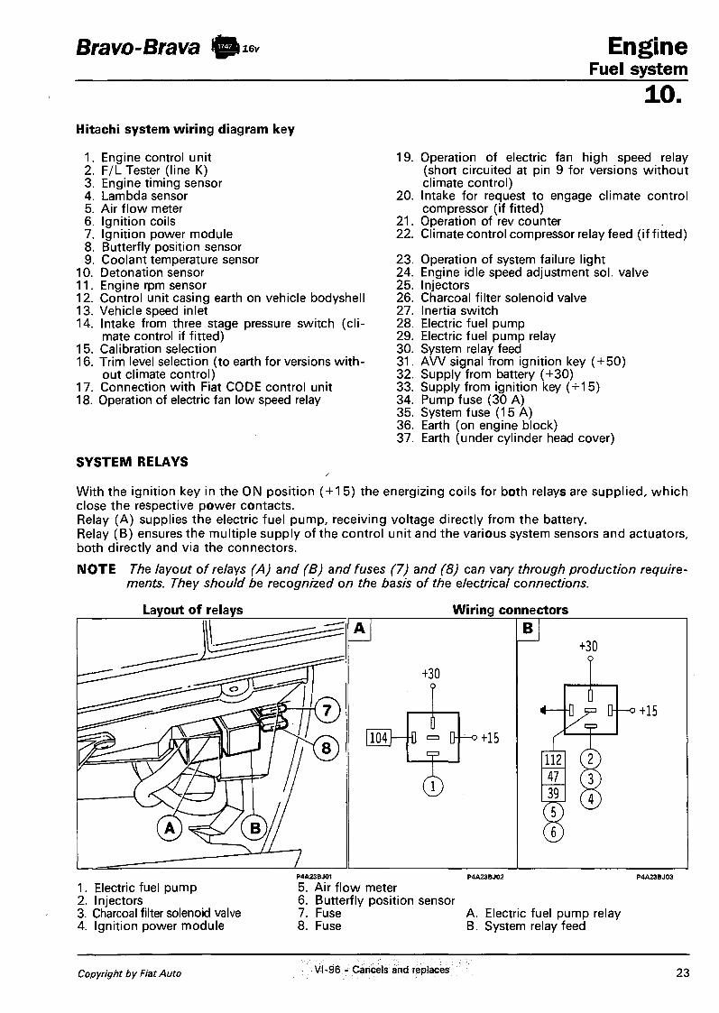
Bravo-Brava @ 16v Engine Fuel system
10. Hitachi system wiring diagram key
1. Engine control unit 2. F/L Tester (line K) 3. Engine timing sensor 4. Lambda sensor 5. Air flow meter 6. Ignition coils 7. Ignition power module 8. Butterfly position sensor 9. Coolant temperature sensor
10. Detonation sensor 11. Engine rpm sensor 12. Control unit casing earth on vehicle bodyshell 13. Vehicle speed inlet 14. Intake from three stage pressure switch (cli
mate control if fitted) 15. Calibration selection 16. Trim level selection (to earth for versions with
out climate control) 17. Connection with Fiat CODE control unit 18. Operation of electric fan low speed relay
SYSTEM RELAYS
19. Operation of electric fan high speed relay (short circuited at pin 9 for versions without climate control)
20. Intake for request to engage climate control compressor (if fitted)
21. Operation of rev counter 22. Climate control compressor relay feed (if fitted)
23. Operation of system failure light 24. Engine idle speed adjustment sol. valve 25. Injectors 26. Charcoal filter solenoid valve 27. Inertia switch 28. Electric fuel pump 29. Electric fuel pump relay 30. System relay feed 31. A W signal from ignition key ( + 50) 32. Supply from battery (+30) 33. Supply from ignition key (+15) 34. Pump fuse (30 A) 35. System fuse (15 A) 36. Earth (on engine block) 37. Earth (under cylinder head cover)
With the ignition key in the ON position ( + 15) the energizing coils for both relays are supplied, which close the respective power contacts. Relay (A) supplies the electric fuel pump, receiving voltage directly from the battery. Relay (B) ensures the multiple supply of the control unit and the various system sensors and actuators, both directly and via the connectors.
NOTE The layout of relays (A) and (B) and fuses (7) and (8) can vary through production requirements. They should be recognized on the basis of the electrical connections.
Layout of relays Wiring connectors
1. Electric fuel pump 2. Injectors 3. Charcoal filter solenoid valve 4. Ignition power module
5. Air flow meter 6. Butterfly position sensor 7. Fuse 8. Fuse
A. Electric fuel pump relay B. System relay feed
Copyright by Fiat Auto VI-96 - Cancels and replaces 23

Engine Fuel system
Bravo-Brava © 16v
10. ENGINE RPM SENSOR
The sensor is fixed to the cylinder block-/crankcase: the flywheel is fixed with a crankshaft crank.
Operating principle
The sensor is made up of a tubular casing (1) which houses a permanent magnet (3) and an electrical winding (2). As a result of the flywheel teeth passing by, the magnetic flow produced by the magnet (3) undergoes oscillations resulting from the variation of the gap. These oscillations create an electro-motive force in the winding (2) which produces a voltage which is alternatively positive (tooth facing the sensor) and negative (gap facing the sensor): see paragraph on "signal management". The peak sensor output voltage depends, with other factors being equal, on the distance between the sensor and the tooth (gap).
Wiring connector
The resistance of the sensor can be measured by disconnecting the connector and connecting an ohmmeter to the sensor
Resistance: 570 ± 57 ohm at 20°C
24 Print no. 506.670/07
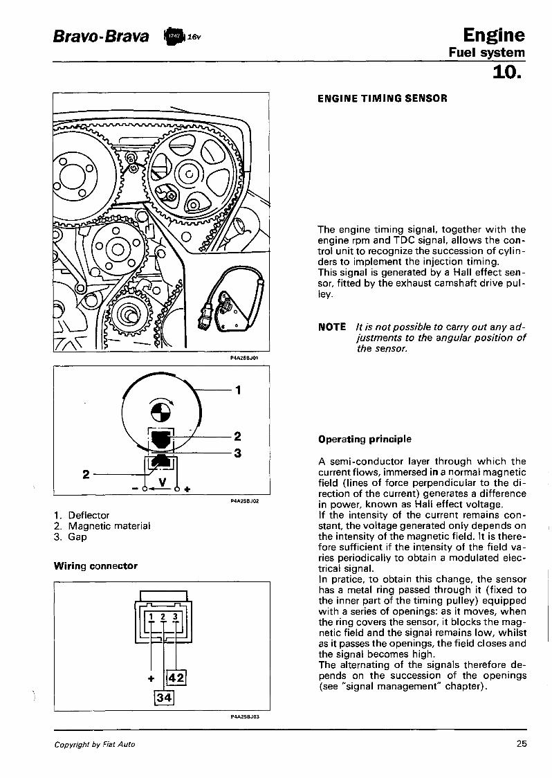
Bravo-Brava 0} 16v Engine Fuel system
10. ENGINE TIMING SENSOR
1. Deflector 2. Magnetic material 3. Gap
Wiring connector
The engine timing signal, together with the engine rpm and TDC signal, allows the control unit to recognize the succession of cylinders to implement the injection timing. This signal is generated by a Hall effect sensor, fitted by the exhaust camshaft drive pulley.
NOTE It is not possible to carry out any adjustments to the angular position of the sensor.
Operating principle
A semi-conductor layer through which the current flows, immersed in a normal magnetic field (lines of force perpendicular to the direction of the current) generates a difference in power, known as Hall effect voltage. If the intensity of the current remains constant, the voltage generated only depends on the intensity of the magnetic field. It is therefore sufficient if the intensity of the field varies periodically to obtain a modulated electrical signal. In pratice, to obtain this change, the sensor has a metal ring passed through it (fixed to the inner part of the timing pulley) equipped with a series of openings: as it moves, when the ring covers the sensor, it blocks the magnetic field and the signal remains low, whilst as it passes the openings, the field closes and the signal becomes high. The alternating of the signals therefore depends on the succession of the openings (see "signal management" chapter).
Copyright by Fiat Auto 25
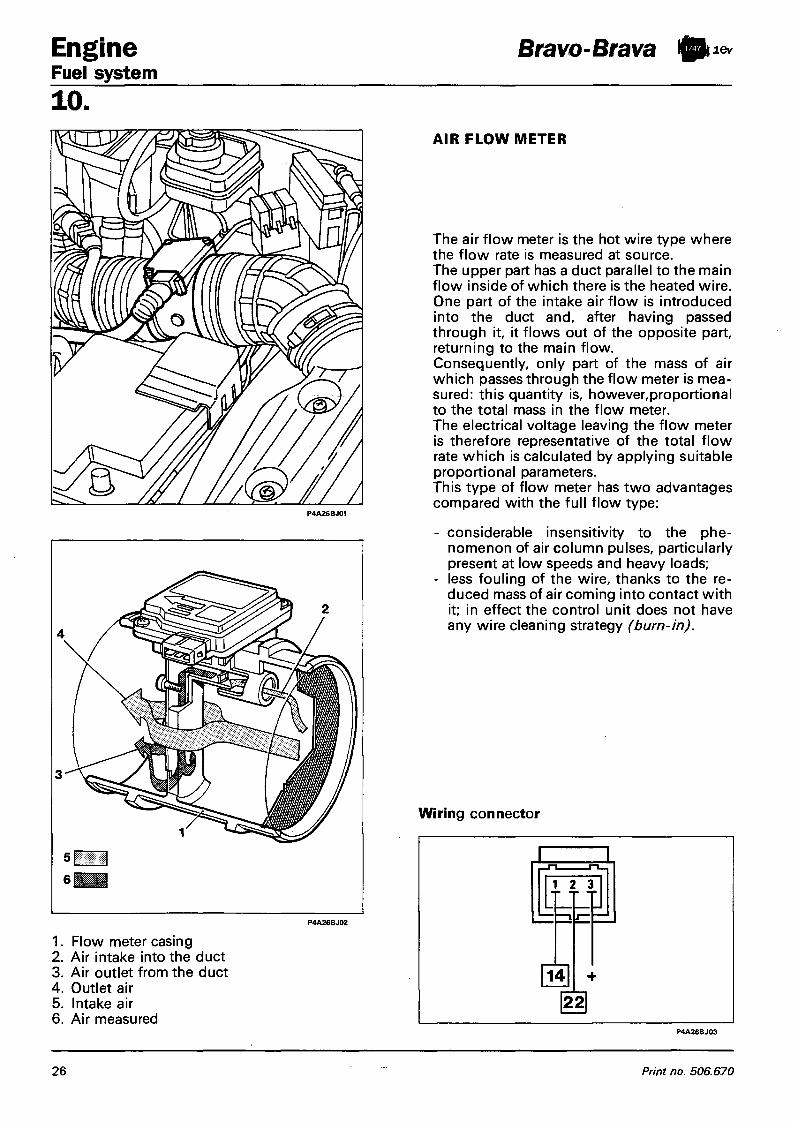
Engine Fuel system
Bravo-Brava 0 lev
10. AIR FLOW METER
1. Flow meter casing 2. Air intake into the duct 3. Air outlet from the duct 4. Outlet air 5. Intake air 6. Air measured
The air flow meter is the hot wire type where the flow rate is measured at source. The upper part has a duct parallel to the main flow inside of which there is the heated wire. One part of the intake air flow is introduced into the duct and, after having passed through it, it flows out of the opposite part, returning to the main flow. Consequently, only part of the mass of air which passes through the flow meter is measured: this quantity is, however,proportional to the total mass in the flow meter. The electrical voltage leaving the flow meter is therefore representative of the total flow rate which is calculated by applying suitable proportional parameters. This type of flow meter has two advantages compared with the full flow type:
- considerable insensitivity to the phenomenon of air column pulses, particularly present at low speeds and heavy loads;
- less fouling of the wire, thanks to the reduced mass of air coming into contact with it; in effect the control unit does not have any wire cleaning strategy (burn-in).
Wiring connector
P4A26BJ03
26 Print no. 506.670

Bravo-Brava I 0 i lev Engine Fuel system
10.
0,7 0,8 0,9 1,0 1,1 1,2 1,3
lambda = 1: stoichiometric mixture lambda < 1 : rich mixture, the CO values tend to be high lambda > 1 : lean mixture, the CO values tend to be low
Wiring connector
LAMBDA SENSOR
The Lambda sensor measures the oxygen content in the exhaust gases: it is fitted on the exhaust pipe upstream of the catalytic si lencer. The sensor output signal is sent to the control unit to correct (feed-back) the mixture strength. When the sensor supplies a low signal (voltage below 200 mV) the control unit recognizes a lean mixture and increases the injection time; subsequently, when the sensor signal is high (voltage above 800 mV), the control unit recognizes a rich mixture and decreases the injection time. This sequence of operations is repeated with a frequency in the order of tens of Hertz, so that the engine operates with a mixture strength constantly oscillating around the stoichiometric value. At temperatures below 300°C the ceramic material is not activated, therefore the sensor does not send reliable signals: to ensure rapid heating during starting and to maintain the temperature during idling, the sensor is equipped with a heater where the electrical resistance is always on.
The sensor can be rapidly put out of action by the presence of even the smallest amounts of lead in the fuel.
The resistance of the sensor heater can be measured by disconnecting the connector and connecting an ohmmeter as shown in the diagram.
Resistance: 4,5 ± 0,5 ohm at 20°C
Copyright by Fiat Auto 27

Engine Fuel system
Bravo-Brava 10k 16v
10. BUTTERFLY POSITION SENSOR
It is made up of a single track potentiometer where the moving part is rotated by the accelerator butterfly shaft.
Wiring connector
COOLANT TEMPERATURE SENSOR
The sensor is fitted on the thermostat. It is made up of a brass casing which protects the resistive element made up of an NTC (Negative Temperature Coefficient) thermistor where the electrical resistance decreases as the temperature increases. The reference voltage is 5 Volt: since the control unit input circuit is designed as a voltage divider, the reference voltage is shared between a resistance in the control unit and the actual sensor. As a result the control unit is capable of evaluating the variations in the sensor resistance through the changes in voltage.
Wiring connector
28 Print no. 506.670

Bravo-Brava 0 16v
Wiring connector
Engine Fuel system
10. VEHICLE SPEED SENSOR
The sensor is positioned on the differential outlet, by the left drive shaft coupling and transmits the information relating to the vehicle speed to the control unit: the signal is also used for the operation of the speedometer. The sensor is the Hall effect type (see "engine timing sensor" paragraph) and it is calibrated so that for each impulse there is a corresponding travel of one metre: on the basis of the frequency of the impulses it is therefore possible to know the speed of the vehicle.
Wiring connector
DETONATION SENSOR
This sensor is the piezoelectric type and is fitted on the engine crankcase in a symmetrical position in relation to the pairs of cylinders 1-2 and 3-4. This position is determined by the need to detect the start of detonation similarly for all cylinders. When there is detonation, vibrations of a particular frequency are created in the crankcase which are transformed by the sensor into a signal whose voltage is proportional to their intensity.
Copyright by Fiat Auto 29

Engine Bravo-Brava Fuel system 10. IGNITION SYSTEM
The ignition circuit is the static advance inductive discharge type. The power module is outside of the control unit, whilst the high tension is supplied by four ignition coils fitted directly on the spark plugs (top-plug type coils). The primary winding for each coil is supplied by the battery voltage via the system relay and is connected to the control module for connection to earth. The optimum ignition advance is calculated by the control unit depending on the engine speed and load and is implemented in the form of the time between the moment in which the primary circuit supply is interrupted and the explosion stroke TDC.
1. Coil for cylinder 1 2. Coil for cylinder 2 3. Coil for cylinder 3 4. Coil for cylinder 4
5. Ignition power module 6. System relay 7. Fuse
30 Print no. 506.670

Bravo-Brava 16v Engine Fuel system
10. IGNITION POWER MODULE
The power module, located on the side of the inlet manifold, is basically an electronic switch which, by means of the impulses coming from the control unit, controls the current in the ignition coil primary winding. Through a particular circuit it limits the current which circulates in the coil primary winding when the maximum value is reached in order to reduce the heating of the actual module. To prevent the overheating of the coil if the ignition takes place with the engine switched off, the module has a rest closing device when the ignition impulses cease arriving from the control unit.
Wiring connector
A: module input B: module output C: ignition coil
• 0 711 B
+ —
+ +
IGNITION COIL
The coil used is the closed magnetic circuit type with the windings in a plastic container immersed in epoxide resin. The coil is connected directly to the spark plug by a silicon material extension which has high dielectric characteristics. The earth for the secondary circuit is obtained with a special cable as the coil is insulated by the cylinder head.
Copyright by Fiat Auto 31

Engine Fuel system 10
Bravo-Brava 10M*
DIAGRAM SHOWING INTAKE CIRCUIT
P4A32BJ01
1. Air filter 2. Air flow meter 3. Inlet 4. Butterfly casing 5. Engine idle adjustment solenoid valve 6. Inlet manifold 7. Exhaust manifold
32 Print no. 506.670

Bravo-Brava ® M < * Engine Fuel system
10. INTAKE CIRCUIT
The intake circuit is made up of the following components: - air filter with relevant sleeves; - acoustic resonator fitted in parallel to the inlet sleeve; - inlet manifold, on which the fuel manifold is fitted; - butterfly casing, where the butterfly position sensor, the PCV valve (Positive Crank Ventilation) for
the oil vapour recirculation circuit and tne engine idle adjustment solenoid valve are fitted.
BUTTERFLY CASING
The butterfly casing has the task of metering the quantity of air supplied to the engine (and therefore the power developed) according to the driver's request via the accelerator control. The butterfly casing is fixed to the inlet manifold by four bolts: the butterfly is opended by means of levers which create a small opening which, consistent with the pedal travel, produce small butterfly openings with the pedal gently pressed and viceversa large angle openings with the pedal strongly pressed. With the pedal completely released (engine decelerating or idling) the additional air required is supplied by the engine idle adjustment solenoid valve: under these circumstances the butterfly opening lever is in contact with screw which prevents the butterfly from being locked in the closed position.
To prevent the formation of ice in the butterfly and the port connected to the PCV valve, the butterfly casing is heated with a small amount of coolant coming from the engine thermostat circulating in a chamber inside the actual casing. The PCV valve for the oil vapour recirculation system and the butterfly position sensor are also fitted on the butterfly casing.
The screw is adjusted during operation by fluxing in the factory and should never be tampered with.
1. Screw 2. Butterfly position sensor 3. Engine coolant inlet 4. Engine coolant outlet
5 r\r*\ I I P 4 A 3 3 B J 0 Z
. PCV valve 6. Accelerator control lever 7. Accelerator cable adjustment bracket 8. Engine idle speed adjustment solenoid
valve
Copyright by Fiat Auto 33

Engine Fuel system
Bravo-Brava !0k 16v
10. ENGINE IDLE SPEED SOLENOID VALVE
ADJUSTMENT
The solenoid valve, fitted on the butterfly casing, intercepts the flow of air which, coming from the air upstream of the butterfly, returns it downstream: it has the task of ensuring the additional air for the engine with the butterfly closed, in all conditions where it is required (idle, deceleration). The valve is the proportional type where the shutter is fixed to a metal core surrounded by an electrical winding.
ON
OFF — I
B ON
OFF
Operation in duty-cycle
A: mainly OFF signal = low effective value mainly ON signal = high effective value
B: effective value
V:
Operating principle
The position of the shutter depends on the intensity of the effective value of the current passing through the winding which creates a magnetic field which attracts the core. The vairation in the effective value is obtained by modulating the winding electrical supply (operation in duty-cycle). This operation consists of varying the battery voltage value (12 Volt nominal) until zero at a frequency where the shutter is not capable of moving following the instant voltage value, but reaches an intermediate position which depends on the proportion between the voltage presence time and the absence time.
Wiring connector
34 Print no. 506.670
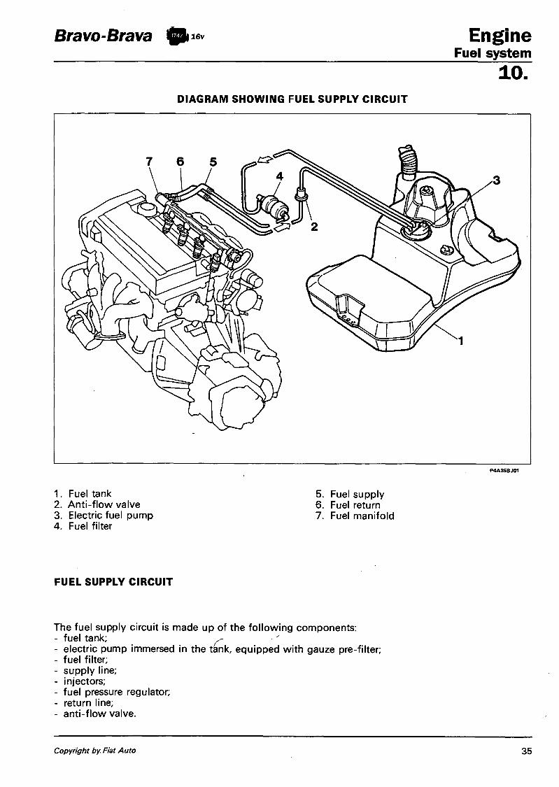
Bravo-Brava ft 16v Engine Fuel system
10. DIAGRAM SHOWING FUEL SUPPLY CIRCUIT
1. Fuel tank 2. Anti-flow valve 3. Electric fuel pump 4. Fuel filter
5. Fuel supply 6. Fuel return 7. Fuel manifold
FUEL SUPPLY CIRCUIT
The fuel supply circuit is made up of the following components: - fuel tank; ^ - electric pump immersed in the tank, equipped with gauze pre-filter; - fuel filter; - supply line; - injectors; - fuel pressure regulator; - return line; - anti-flow valve.
Copyright by Fiat Auto 35

Engine Bravo-Brava ft** Fuel system 10. ELECTRIC FUEL PUMP
The pump is housed inside the fuel tank on a special tray which also supports the fuel level gauge and is fitted with a gauze filter at the pump inlet. The pump is the volumetric type (G-Rotor) and is designed to run on unleaded fuel. The rotor is moved by a direct current motor supplied at the battery voltage directly by the appropriate relay operated by the control unit. The motor is immersed in the fuel which has a detergent and cooling effect on the blades and the manifold. The pump is equiped with an excess pressure valve, which short circuits the supply with the inlet if the pressure in the supply circuit exceeds 5 bar, to prevent the electric motor from overheating. In addition, a one-way valve on the supply prevents the draining of the entire fuel circuit when the pump is not working. The nominal capacity of the pump varies according to theangular speed of the rotor and therefore the supply voltage: with a voltage of 12 V it is around 140 l/h.
1. electrical connectors 2. supply port 3. inlet port 4. excess pressure
valve 5. one-way valve
FUEL FILTER
The filter, protected by a shield fixed under the bodyshell, is inserted along the fuel supply pipe. It is made up of a steel casing and a polyurethane internal support which has a high filtering capacity element.
NOTE
A
There is an arrow on the outer casing which indicates the direction of the flow of the fuel and the correct fitting position.
The fuel filter should be changed at intervals of 30,000 Km.
1. Fuel inlet 2. Fuel outlet
36 Print no. 506.670
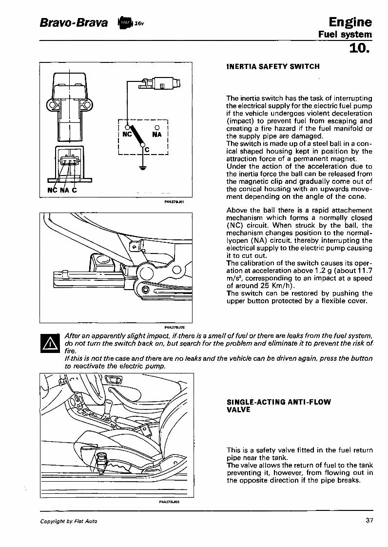
Bravo-Brava ft 16v Engine Fuel system
10.
E
I N C X NA
I I
NC NA C
A
INERTIA SAFETY SWITCH
The inertia switch has the task of interrupting the electrical supply for the electric fuel pump if the vehicle undergoes violent deceleration (impact) to prevent fuel from escaping and creating a fire hazard if the fuel manifold or the supply pipe are damaged. The switch is made up of a steel ball in a conical shaped housing kept in position by the attraction force of a permanent magnet. Under the action of the acceleration due to the inertia force the ball can be released from the magnetic clip and gradually come out of the conical housing with an upwards movement depending on the angle of the cone.
Above the ball there is a rapid attachement mechanism which forms a normally closed (NC) circuit. When struck by the ball, the mechanism changes position to the normal -lyopen (NA) circuit, thereby interrupting the electrical supply to the electric pump causing it to cut out. The calibration of the switch causes its operation at acceleration above 1.2 g (about 11.7 m/s 2, corresponding to an impact at a speed of around 25 Km/h). The switch can be restored by pushing the upper button protected by a flexible cover.
After an apparently slight impact, if there is a smell of fuel or there are leaks from the fuel system, do not turn the switch back on, but search for the problem and eliminate it to prevent the risk of fire. If this is not the case and there are no leaks and the vehicle can be driven again, press the button to reactivate the electric pump.
SINGLE-ACTING ANTI-FLOW VALVE
This is a safety valve fitted in the fuel return pipe near the tank. The valve allows the return of fuel to the tank preventing it, however, from flowing out in the opposite direction if the pipe breaks.
Copyright by Fiat Auto 37

Engine Bravo-Brava ft** Fuel system 10. FUEL MANIFOLD
The fuel manifold, which has the function of distributing the fuel to the injectors, is made from die-cast aluminium and incorporates the housings for the injectors and for the pressure regulator. The fuel inlet is achieved with a sealed fixing bolt. The fuel recirculation is obtained by means of a pipe inside the manifold connected at one end to the regulator and at the other end to the outer fuel return pipe to the tank.
1
2 P4A38BJ01
FUEL PRESSURE REGULATOR
This is a differential diaphragm device, adjusted during manufacture to a pressure of 3.00 ± 0.05 bar. The fuel under pressure, coming from the pump, exerts a force on the flow valve (7) opposed by the calibrated spring (8). When the calibration pressure is exceeded, the flow valve opens and the excess fuel returns to the tank, thereby stabilizing the pressure in the circuit. In addition, via the pick up (9), the vacuum in the inlet manifold (at which the nose of the injector) also finds itself, acts on the regulator diaphragm, reducing the load exerted by the calibration spring. In this way the differential in pressure between the fuel and the environment (inlet manifold) in which the injector finds itself in all engine operating conditions is kept constant. Consequently, the injector flow rate (for a certain supply voltage) depends only on the injection time established by the control unit.
NOTE The pressure is assumed by the control unit as a fixed parameter: as a result the regulator should never be tampered with so as not to alter the mixture strength for the engine.
38 Print no. 506.670

Bravo-Btava ft lev Engine Fuel system
10.
1. Fuel inlet 2. Deflector 3. Jet 4. Nose 5. Jet of fuel 6. Electrical connector
Wiring connector
INJECTORS
The injectors have the task of supplying the quantity of fuel required for the operation of the engine: the fuel is injected into the inlet manifold, immediately upstream of the inlet valve. The injector is the "top-feed" type, with the supply of the fuel from the rear of the casing, where the electrical winding connected to the connector (6) is also housed. When the current passes through the winding, the magnetic field produced attracts the shutter causing the opening of the injector and the flow of fuel. As the pressure differential between the inside and the outside of the injector is constant (thanks to the presence of the regulator), the quantity of fuel supplied, like the electrical voltage, only depends on the opening time, established by the control unit. The end section of the injector or nose (4) is fitted with a jet (3) which gives the fuel a rotary motion, thanks to a deflector (2) fitted with four tangentially positioned flow ports.
The resistance of the injector can be measured by disconnecting the connector and connecting an ohmmeter as shown inthe diagram. Value of the resistance: 12 ± 1,2 ohm.
Copyright by Fiat Auto 39

Engine Bravo-Brava ft** Fuel system 10. EMISSION CONTROL DEVICES
The devices used have two objectives: - to keep down the pollutant substances present in the exhaust, via the catalytic silencer; - to eliminate the dispersion towards the outside of the unburnt hydrocarbons, via the (fuel) anti-evap
oration system and the (lubrication) oil vapour recirculation system.
CATALYTIC SILENCER
The catalytic silencer is a device which makes it possible to simultaneously keep down the three main pollutant compounds present in the exhaust: unburnt hydrocarbons (HC), carbon monoxide (CO) and nitrogen oxide (NOx). Two types of chemical reaction take place inside the catalyzer: - oxidation of the CO and the HC, converted into carbon dioxide (CO2) and water (H2O); - reduction of the NOx, converted into Nitrogen (N2). These reactions can take place in extremely short periods of time thanks to the presence inside the catalyzer structure (ceramic support) of a layer of active substances (platinum and rhodium) which greatly accelerate the conversion speed of the harmful substances. The effectiveness of this conversion process is conditioned by the fact that the mixture strength at which the engine operates is constantly oscillating around the stoichiometric value, which is achieved thanks to the feed-back control carried out by the control unit on the basis of the Lambda sensor signals. Lastly, the conversion processes are activated at temperatures in excess of 300 - 350°C: it is therefore vital that the catalyzer reaches this temperature as soon as possible in order to work properly.
1. Ceramic monolith 2. Metal support 3. Steel outer casing
When it is necessary to operate near the catalytic silencer, it is necessary to leave the vehicle to rest for some time, since the (internal) operating temperature of the catalyzer is between 500 and 850°C.
There are basically two causes of the destruction of the inside of the catalyzer:
- the presence of lead in the fuel which lowers the degree of conversion at levels of practically nil ("lead poisoning") and which also irreparably damages the Lambda sensor;
- the presence of totally unburnt fuel in the exhaust gases, due to failed ignition, which causes an increase in the temperature which involves the fusion of the ceramic support. As a result, the connector for the coils should never be disconnected with the engine running: in the case of tests, the silencer should be replaced first with an equivalent section of pipe.
40 Print no. 506.670

Bravo-Brava ft 16v Engine Fuel system
10.
Exhaust system with catalytic converter
1. CO socket
FUEL ANTI-EVAPORATION SYSTEM
2. Lambda sensor 3. Catalytic silencer
Location of anti-evaporation system components
1. Fuel tank 2. Vapour separator 3. Float valve 4. Cap with safety valve 5. Engine control unit
6. Charcoal filter 7. Charcoal filter solenoid valve 8. Multi-purpose valve 9 . Inlet manifold
1 0 . Relay
Copyright by Fiat Auto 41

Engine Bravo-Brava ft*» Fuel system 10. Operating principle
The anti-evaporation system has the aim of preventing the fuel vapours, made up of the lightest parts of the hydrocarbons which basically form in the tank, from being discharged into the atmosphere. The system operates, above all at high outside temperatures when the temperature of the fuel increses and consequently the tendency towards evaporation increases: in this situation there is an increase in the pressure inside the tank. In particular, even with the tank (1) full, with the vehicle stationary the two float valves (3) remain open as they are located higher than the breather pipe and therefore they allow the vapours to reach the separator (2) from where they mainly return to the tank as they condense. If, on the other hand, there is strong splashing when the vehicle is driving or it overturns, the valves (3) close preventing fuel from escaping. When the pressure inside the tank reaches about 30-40 mbar, the multi-purpose valve (8) opens and the fuel vapours reach the charcoal filter (6). The valve (8) also allows an intake of air into the tank through the charcoal filter if necessary following the lowering of the level of fuel and the consequent vacuum which is created inside the tank. When the engine is running, the control unit operates the charcoal filter solenoid valve which allows the intake of vapours by the engine and the consequent scavenging of the charcoal filter. If as a result of the malfunction of one of the components, the pressure inside the tank increases to dangerous levels, the safety valve located in the cap (4) allows the pressure to be discharged outwards. If necessary, this valve can open in the opposite direction, to ventilate the tank and prevent the vacuum reaching excessive values.
1. Fuel tank 2. Vapour separator 3. Float valve 4. Cap with safety valve 5. Engine control unit
6. Charcoal filter 7. Charcoal filter solenoid valve 8. Multi-purpose valve 9. Inlet manifold
10. Relay
42 Print no. 506.670

Bravo-Brava Engine Fuel system
10. Float valve
The float valve has the task of allowing the flow of vapours towards the separator, without, however, allowing the escape of liquid fuel. The valve contains a float, one end of which closes the valve outlet port in the following conditions: - strong side acceleration (vehicle taking a bend) or longitudinal acceleration (vehicle braking) with
the relevant movement of the mass of fuel as a result of the inertia force; - overturning of the vehicle.
P4A43BJ03
1. Normal operating conditions: valve open 2. The fuel pushes the float upwards as a result of strong acceleration: valve closed 3. Vehicle overturned: valve closed
Fuel vapour separator and multi-purpose valve
The fuel vapours coming from the tank reach the vapour separator (3), located at the side of the fuel filler, via the pipes (4). Part of the vapours condense and return to the tank via the same pipes (4), whilst the remaining vapours escape from the separator through the multi-purpose valve (2) and are directed to the active charcoal filter via the pipe (1).
1. Pipe connecting fuel vapour separator to the active charcoal filter
2. Multi-purpose valve
3. Fuel vapour separator 4. Pipes connecting vapour separator to the
fuel tank
Copyright by Fiat Auto 43

Bravo-Brava ft 16v
Safety and ventilation valve
This valve is located in the fuel filler cap and carries out the following functions: - discharging the excess pressure outwards
which forms inside the tank (safety function); the pressure acts on the plate (2) and, overcoming the spring (1) loading, allows the excess vapours to be discharged outwards;
- allowing the flow of outside air in the tank when an excessive vacuum is formed inside the tank through the effect of the fuel consumption (ventilation function): when the vacuum exceeds the loading of the spring (4), it moves the valve (3), allowing the intake of air.
Engine Fuel system 10.
i P4A44BJ03
Active charcoal filter
This is made up of granules of charcoal (4) which trap the vapours entering through the inlet (5). The scavenging air which enters through the inlet (1), passes through the paper filter (3), comes into contact with the charcoal granules removing the vapours and directs them towards the outlet (2) and from there towards the filter valve. The air, having entered through the inlet (5) can also be sent by the vacuum into the tank for ventilation. The partition (6) ensures that the warm scavenging air drawn in comes into contact with all the granules of charcoal. There are also two springs (7) which allow the expansion of the mass of granules when the pressure increases.
Charcoal filter solenoid valve
This valve, of the normally closed type, controls the flow of vapours reaching the inlet manifold and is operated by the control unit with duty-cycle operation.
NOTE The inlet which has the word CAN (canister) written on it should be connected to the charcoal filter.
1. From the charcoal filter 2. To the inlet manifold
44 Print no. 506.670

Bravo-Brava ft 16v Engine Fuel system
10. PROCEDURE FOR DISMANTLING THE RAPID ATTACHMENT PIPE FOR THE ANTI-EVAPORATION SYSTEM FROM THE INLET MANIFOLD
The pipe for the anti-evaporation system (1) is held in place on the inlet manifold cartridge (2) by the small clamp (3). A flexible washer (4) keeps the cartridge (2) in its housing preventing any fuel vapours from escaping by means of an O ring (5).
1. Anti-evaporation system rapid attachment pipe
2. Cartridge 3. Pipe retaining clamp 4. Flexible washer 5. 0-ring
In order to extract the pipe (1), push the clamp (3 with your fingers towards the manifold and, at the same time, extract the actual pipe. The operation can also be carried out with the help of an 11 mm spanner to facilitate the movement of the clamp (3) towards the manifold.
A Do not use tools to extract the pipe which could damage the system.
P4A44BJ06
Copyright by Fiat Auto II-97 - Update 4 4 / 1

Engine Fuel system
Bravo-Brava ft**
10. Replacing clamp
A kit is available for replacing the clamp which comprises an 0-ring (5) and a clamp (3). After having removed the pipe for the anti-evaporation system, insert your fingers between the clamp (3) and the cartridge casing (2) (to facilitate the operation, move the clamp aside using a screwdriver, working very carefully). Pull outwards and rotate the actual clamp.
Extract the 0-ring (5) inside the cartridge. Clean the interior of the cartridge with an air jet and insert the new O-ring in its housing; then insert the new clamp.
Clean all impurities from the end section of the pipe before it is inserted inside the cartridge. Insert the pipe pushing it into the end of travel position.
4 4 / 2 11-97 - Update Print no. 506.670/09

Bravo-Brava ft*» Engine Fuel system
10. S Y S T E M FOR RECIRCULATING G A S E S COMING FROM THE CRANKCASE (BLOW-BY)
This system controls the emissions from the crankcase of breather gases, made up of mixtures of air, fuel vapours and burnt gases which escape through the piston seals and of lubricant oil vapours, drawing them in again and burning them in the engine. The breather gases coming from the crankcase reach the cylinder head and are directed into two different inlets (1) and (2). With the butterfly open, the gases flow through the inlets (1) and (2) to be drawn into the manifold. With the butterfly closed the vacuum in the inlet manifold draws in the gases through the intake (1) in which there is a PCV limiting valve (3) (Positive Crank Ventilation) which shutters the intake. The PCV valve, in effect, can be modulated and the quantity of gases which pass through is proportional to the vacuum in the inlet manifold. When the butterfly valve is completely open (condition A) , the vacuum inside the inlet manifold is minimal, the spring (5) is completely extended and the PCV valve allows the maximum flow of breather gases. Viceversa, with the butterfly completely closed (condition B) , the vacuum inside the manifold is maximum, this causes the movement of the piston (4) which shutters the opening for the flow of breather gases inside the PCV valve and thereby restricts the intake into the manifold of the actual gases.
P4A45BJ01
1. Inlet on butterfly casing with PCV 2. Inlet on sleeve 3. PCV valve 4. Piston 5. Spring
Copyright by Fiat Auto 45

Engine Fuel system
Bravo-Brava ft 16v
10. TIGHTENING TORQUES
The main tightening torques for the HITACHI injection/ignition system components are given below (values in Nm).
butterfly casing 6,3 ± 0,4
PCV valve (on butterfly casing)
18,0 ± 2,0
vehicle speed sensor
22,5 ± 2,5
engine rpm sensor
40 ± 0,5
ignition power module
2,5 ± 0,5
detonation sensor 20,0 ± 5,0
46 Print no. 506.670
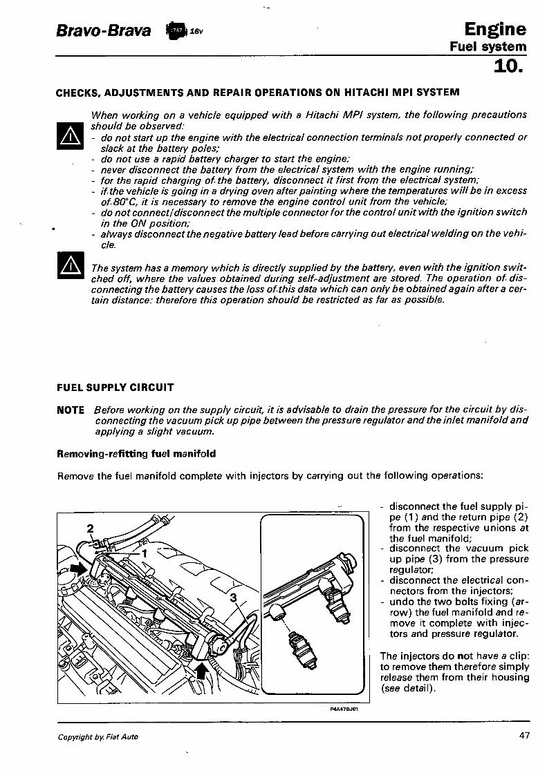
Bravo-Brava ft** Engine Fuel system
10. CHECKS, ADJUSTMENTS AND REPAIR OPERATIONS ON HITACHI MPI SYSTEM
When working on a vehicle equipped with a Hitachi MPI system, the following precautions should be observed: - do not start up the engine with the electrical connection terminals not properly connected or
slack at the battery poles; - do not use a rapid battery charger to start the engine; - never disconnect the battery from the electrical system with the engine running; - for the rapid charging of the battery, disconnect it first from the electrical system; - if the vehicle is going in a drying oven after painting where the temperatures will be in excess
of 80°C, it is necessary to remove the engine control unit from the vehicle; - do not connect/disconnect the multiple connector for the control unit with the ignition switch
in the ON position; - always disconnect the negative battery lead before carrying out electrical welding on the vehi
cle.
The system has a memory which is directly supplied by the battery, even with the ignition switched off, where the values obtained during self-adjustment are stored. The operation of disconnecting the battery causes the loss of this data which can only be obtained again after a certain distance: therefore this operation should be restricted as far as possible.
FUEL SUPPLY CIRCUIT
NOTE Before working on the supply circuit, it is advisable to drain the pressure for the circuit by disconnecting the vacuum pick up pipe between the pressure regulator and the inlet manifold and applying a slight vacuum.
Removing-refitting fuel manifold
Remove the fuel manifold complete with injectors by carrying out the following operations:
- disconnect the fuel supply pipe (1) and the return pipe (2) from the respective unions at the fuel manifold;
- disconnect the vacuum pick up pipe (3) from the pressure regulator;
- disconnect the electrical connectors from the injectors;
- undo the two bolts fixing (arrow) the fuel manifold and remove it complete with injectors and pressure regulator.
The injectors do not have a clip: to remove them therefore simply release them from their housing (see detail).
P4A47BJ01
Copyright by Fiat Auto

Engine Fuel system
Bravo-Brava ft 16v
10.
Removing-refitting electric fuel pump
Proceed with the removal of the pump as follows: - working from the luggage compartment,
remove the cover to gain access to the pump housing cover;
- undo the three fixing bolts (arrow) and remove the cover (1);
- undo the union (2) fixing the breather pipe and remove the pipe;
- disconnect the electrical connector for the fuel level gauge (3) and the one for the pump (4) supply;
- remove the rapid attachment fuel supply (5) and return (6) unions from the tray;
NOTE When removing and refitting the rapid unions, refer to the procedures given in the service notes.
fit tool 1860893000 on the tray fixing flange, taking care to insert it correctly between the projections on the flange, as shown in the diagram;
undo the flange and remove it together with the tool, then carefully remove the tray complete with seal.
48 Print no. 506.670

Bravo-Brava ft mi6v Engine Fuel system
10.
With the drip tray removed, proceed as follows:
1. disconnect the pump supply connector from the drip tray;
2. lift up the pump and extract it by bending it sideways, as shown in the diagram.
Then open the band fixing the supply pipe and remove the pipe from the pump. Lastly, remove the gauze filter from the pump.
Removing-refitting fuel filter
Raise the vehicle, then proceed as follows:
1. unto the four bolts and the nut (arrow) fixing the shield and remove the shield;
2. disconnect the fuel rapid inlet ( 1 ) and outlet (2) connectors from the filter and collect the fuel which comes out during the operation in a suitable container, then seal the connectors without either bending or twisting the pipes; lastly, undo the fixing bolt (arrow) and remove the filter.
NOTE When removing and refitting the rapid connectors, refer to the procedures described in the service notes.
A The fuel filter should be replaced every 40,000 km. After replacing the filter, start up the engine and check that no fuel is leaking from the connectors.
Copyright by Fiat Auto VI-96 - Cancels and replaces 49

Engine Bravo-Brava ftuev Fuel system
10. FUEL CIRCUIT PRESSURE CHECKS
Checking fuel regulation pressure
Disconnect the pipe coming from the filter (shown by the arrow) from the injector fuel manifold. Place pressure gauge 1895890000 and two taps (1) and (2) between the end of the disconnected pipe and the fuel manifold, as illustrated in the diagram.
Supply the electric pump with the engine switched off through the "active diagnosis" function of the F/L Tester. Alternatively, proceed as follows: - extract the pump relay from the socket - make a connection as shown in the diagram using a suitable bridge for this purpose. The pressure reading on the gauge should stabilize, in these conditions, at 3.0 bar ± 0.2 bar. If the pressure is too low, carry out the next test.
Checking maximum fuel supply pressure (or efficiency of electric pump)
Keeping the same connections as for the previous test, close the tap (2) located downstream of the pressure gauge, operate the electric pump with the engine switched off, as described for the previous test: the pressure should reach 5 bar and not exceed 7 bar (pump safety valve setting). If this is not the case, replace the electric pump because it is defective.
50 Print no. 506.670/07

Bravo-Brava ft** Engine Fuel system
10. If the pressure value in the previous test was higher than 3.0 bar it is necessary to: - disconnect the fuel return pipe from the pressure regulator and replace it, temporarily, with a pipe
which, inserted on the filler, allows the return of fuel to the tank. - supply the electric pump with the engine switched off as described in the previous test, then read off
the pressure value on the gauge: 1. if it reaches 3.0 bar then the fuel return pipe to the tank must be replaced because it is obstructed or
bent;
2. if it exceeds 3.0 bar then the pressure regulator must be replaced because it is defective.
NOTE At the end of the tests refit the pump relay in its housing if it has been removed.
Checking pneumatic part of pressure regulator
Start up the engine and let it idle. The reading on the presure gauge should be around 2.5 bar. If this is not the case, the air connecting pipe between the pressure regulator and the inlet manifold is damaged or the regulator itself is defective and should be replaced.
P4A51BJ01
Checking injector seal
In order to check if the injectors are dripping, make the connection as described for the regulation pressure test. Then proceed as follows: - supply the electric pump with the engine
switched off; - fully close the tap (1) Upstream of the
pressure gauge once the regulation pressure has been reached: in this way the pressure in the fuel manifold and the injectors will be the same;
- switch off the electric pump and observe whether as soon as the pressure stabilizes (i.e. decreases slightly) it remains constant for around 60 sees; if this is not the case, there is a leak from one or more of the injectors or from a union.
In this case, remove the injectorsand the fuel manifold from the inlet manifold, keeping the connection with the pressure gauge. Repeat the previous test leaving the tap (1) open. When supplying the electric pump with the engine switched off, observe whether there is dripping from any connecting sections. Replace any dripping injectors and/or renew any defective seals where there are leaks.
Copyright by Fiat Auto 51

Engine Fuel system
Bravo-Brava ft 16v
10. INTAKE CIRCUIT
Removing-refitting engine idle adjustment solenoid valve and butterfly position sensor - Undo the fixing bolts (arrow) to remove
the engine idle adjustment solenoid valve (1);
- undo the fixing bolts (arrow) to remove the butterfly position sensor (2).
NOTE When refitting the butterfly position sensor, take care that the operating lever fitted on the butterfly shaft (3) is above the sensor driving element (4), as shown in the diagram.
Removing-refitting air flow meter
1. Remove the battery, disconnect the electrical connector (1) from the meter, loosen the bands (2) and (3) fixing the inlet sleeve;
2. disconnect the blow-by sleeve (4) from the inlet sleeve, undo the two bolts (arrow) fixing the flow meter mounting bracket and remove the assembly; then loosen the bands at the flow meter and remove the two sleeves.
P4A52BJ02 P4A52BJ03
52 Print no. 506.670
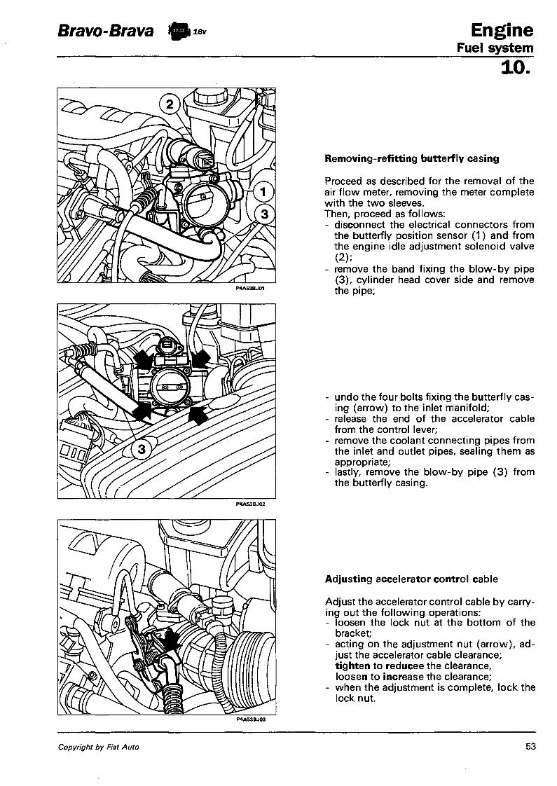
Bravo-Brava
P4A53BJ02
Engine Fuel system
10.
Removing-refitting butterfly casing
Proceed as described for the removal of the air flow meter, removing the meter complete with the two sleeves. Then, proceed as follows: - disconnect the electrical connectors from
the butterfly position sensor (1) and from the engine idle adjustment solenoid valve (2) ;
- remove the band fixing the blow-by pipe (3) , cylinder head cover side and remove the pipe;
- undo the four bolts fixing the butterfly casing (arrow) to the inlet manifold;
- release the end of the accelerator cable from the control lever;
- remove the coolant connecting pipes from the inlet and outlet pipes, sealing them as appropriate;
- lastly, remove the blow-by pipe (3) from the butterfly casing.
P4A53BJ03
Adjusting accelerator control cable
Adjust the accelerator control cable by carrying out the following operations: - loosen the lock nut at the bottom of the
bracket; - acting on the adjustment nut (arrow), ad
just the accelerator cable clearance; tighten to reducee the clearance, loosen to increase the clearance;
- when the adjustment is complete, lock the lock nut.
Copyright by Fiat Auto 53

Engine Fuel system
Bravo-Brava ft 16v
10.
1
2 3
a J
ELECTRICAL CIRCUIT
Removing-refitting engine timing sensor
This operation involves removing the timing belt and the camshaft toothed pulley, exhaust side. Having carried out these operations, it is necessary to: - disconnect the electrical connector; - undo the two fixing bolts (arrow) and re
move the sensor.
When refitting carry out the procedure in the reverse order, following the instructions for fitting and tensioning the toothed belt.
NOTE The sensor does not require any type of adjustment.
Removing-refitting engine rpm sensor
Position the vehicle on a lift, then, working from underneath the vehicle:
- disconnect the electrical connector; - undo the bolt fixing the sensor and remove
it from its housing.
NOTE The sensor is fitted in production with tolerances which ensure a gap of 0.8 ± 0.4 mm without requiring further adjustments. This gap is also ensured if the sensor is replaced with a replacement one.
If you wish to check the gap between the sensor and the flywheel, proceed as follows: - measure the distance between the end of
the sensor and the lower part of the sensor bracket (distance "a");
- measure the distance between the fitting element on the cylinder block/crankcase and the upper part of the tooth (distance "b"), repeating the measurement for at least two opposite teeth. The gap (t = b-a) should be between 0.4 and 1.2 mm.
1. Sensor 2. Fitting element 3. Flywheel tooth
P4A54BJ03
54 Print no. 506.670

Bravo-Brava ft*» Engine Fuel system
10.
Removing-refitting: 1. Lambda sensor 2. Detonation sensor 3. Vehicle speed sensor
P4AS5BJ01
P4A55BJ02 P4ASSBJ03 P4A55BJ04
1. Disconnect the electrical connector, then undo the Lambda sensor and remove it from its housing. 2. Disconnect the electrical connector, undo the bolt fixing the detonation sensor and remove it. 3. Disconnect the electrical connector and undo the casing for the vehicle speed sensor, removing it
from its housing.
P4A5SBJ05
Removing-refitting coolant temperature sensor
- Disconnect the electrical connector from the sensor;
- undo the sensor removing it from its housing.
A Take great care that the sensor is correctly refitted and over the electrical connection, since the information sent by the sensor is also used by the control unit for operating the radiator fan.
Copyright by Fiat Auto 55

Engine Fuel system 10
Bravo-Brava ft**
Removing-refitting ignition coils
Proceed with the removal of the ignition coils by carrying out the following operations: - disconnect the electrical connector; - undo the two fixing bolts and remove the
coil, extracting it from the housing.
NOTE The coil is fitted with an extension made from a silicon material with a high die/electric power inside of which there is a pressure switch with a spring loading. Do not dismantle the two components so as not to risk losing the internal contact or getting it dirty. In the case of replacement, it is not necessary to separate the coil from the extension because the complete coil/extension assembly is available as spares.
Checking primary circuit coil resistance
The resistance is checked by following the diagram.
Primary resistance: 0.6 ± 0.06 ohm
Removing-refitting ignition power module
Remove the ignition power module carrying out the following operations: - disconnect the electrical input and output
connectors (arrow); - undo the two fixing bolts and remove the
module. P4A56BJ04
56 Print no. 506.670

Bravo-Brava ft** Eng ine Fuel system
10.
Removing-refitting engine control unit
The control unit is located under the glove compartment. Proceed with removing the control unit by carrying out the following operations: - remove the glove compartment; - undo the bolt fixing the mounting bracket
and rest the control unit on the floor of the vehicle;
- undo the bolt fixing the earth cable to the bodyshell;
- disconnect the electrical connectors, one by one;
- remove the bracket from the control unit.
CHECKING EMISSION CONCENTRATION
This system manages the content of carbon monoxide (CO) and the idle air flow rate which cannot, however, be manually adjusted. However, checking the content of the exhaust gases upstream and downstream of the catalyzer can provide a useful indication of the injection/ignition system operating conditions, the engine parameters and the catalyzer.
Checking idle concentration of CO and HC upstream of the catalytic silencer
In order to check the concentration of carbon monoxide (CO) and unburnt hydrocarbons (HC) upstream of the catalyzer, proceed as follows:
1. Undo the cap located in the exhaust pipe, upstream of the catalyzer, and tighten the tool in its place. 2. Connect a suitably calibrated CO-tester sensor to the tool. 3. Start up the engine and let it reach operating temperature. 4. Check that the speed is correct. 5. Check that the idle concentration of CO is within the recommended limits (see table); if this is not the
case, it is necessary to check: - that the Lambda sensor is working properly, using the F /L Tester; - for the presence of air penetration in the area surrounding the Lambda sensor housing; - the injection and ignition systme (in particular the state of wear of the spark plugs).
6. In the same conditions, check that the concentration of HC is less than 500 p.p.m. 7. If these values are not found, proceed with checking the engine, paying particular attention to:
- the timing; - the engine compression.
NOTE The engine is fitted with hydraulic tappets for the automatic recovery of the clearances.
Copyright by Fiat Auto 57

Engine Fuel system 10
Bravo-Brava ty™*
P4A58BJ01
Table summarizing pollutant emission tolerance values
CO(%) HC (p.p.m.) CO-2 ( % )
Upstream of the catalyzer 0,4 + 1 < 500 > 12
Downstream of the catalyzer < 0,35 < 90 > 13
Checking exhaust concentration of CO and HC
The concentration of carbon monoxide (CO) and unburnt hydrocarbons (HC) at the exhaust is measured by inserting a suitably calibrated sensor probe at least 30 cm into the end section of the exhaust pipe.
1. Check that the idle CO and HC concentration values are as recommended (see table). 2. If the HC value is outside of the recommended limits, whilst that previously measured upstream of the
catalyzer was okay, then the engine parameters are taken to be correct and the cause of the problem should be sought in the decreased efficiency of the catalyzer.
CHECKING ENGINE IDLE SPEED
If the engine idle speed is not correct as the system is the self-adjusting type it is not possible to carry out any adjustment: therefore it is necessary to check that the accelerator linkage is correctly adjusted and therefore the problem should be sought by means of a complete fault diagnosis using the F / L Tester.
CHECKING IGNITION ADVANCE
In order to check the ignition advance values at different speeds it is necessary to use the F /L Tester diagnostic equipment.
58 Print no. 506.670

Bravo-Brava C lutch • Index
I F 5 1 G 5
page
COMPOSITION AND OPERATION
. - Clutch with mechanical release mechanism 1
- Clutch with hydraulic release mechanisnrf 2
REMOVING-REFITTING
- Removing 4 - Driven disc - pressure plate 4 - Refitting 4
CLUTCH OPERATION
- Thrust bearing . 5 - Fork control shaft 5 - Thrust bearing sleeve 6 - Clutch pedal 6 - Clutch pedal position adjustment 7
- Removi ng - refitting cable clutch control cable 7
- Removing - refitting hydraulically operated clutch components 8
- Clutch pump 8 - Operating cylinder 11 - Bleeding 11
Copyright by Fiat Auto IX-95 - Cancels and replaces

Bravo-Brava Clu tch Composition and operation
IF52G5 ^
CLUTCH WITH MECHANICAL RELEASE MECHANISM (1370 -1581 -1747 -1929 D engines)
The clutch is the dry, single plate type, with the thrust bearing always in contact with the pressure plate spring. The driven disc is driven by the pressure exerted by a diaphragm spring. The clutch release is obtained by means of a cable mechanically operated by the pedal. The mechanical clutches adopted are all the " Thrust" type (see section which follows).
Technical data 1370 1581 1747 1929 D
Spring loading daN 465 450 500 420
External diameter mm 190 200 215 200
Internal diameter mm 130 137 145 137
Pedal travel mm 163 163 163 163
P4A001C02 P4A001C03
Clutch release cable "drawn type cable" (for Clutch release cable "pushing outer cable 1370 12v) type" (for 1581,1747,1929 D)
Copyright by Fiat Auto IX-95 - Cancels and replaces 1

Clutch Composition and operation 18.
Bravo IF53G5
CLUTCH WITH HYDRAULIC RELEASE MECHANISM (1998 20v)
Composition
In order to improve quietness levels and performance, a hydraulic device has been fitted on the 1998 20v version. This device is made up of a reservoir, common to the braking system (1), a pump (2) fixed to the pedals assembly and an operating cylinder (3) fixed to the bell housing.
Driving the vehicle will be more comfortable because there will be a reduction in the vibrations transmitted by the power unit due to the damping effect of the hydraulic system. The adoption of this device dispenses with the need for periodic adjustment because any clearance and the recovery of the wear of the driven disc take place automatically.
1. Tank 2. Clutch pump 3. Operating cylinder
Operation
The clutch is the dry, single plate type, with a hydraulic release mechanism and a thrust bearing always in contact with the spring. The driven disc is driven by means of the pressure exerted by a diaphragm spring.
2 IX-95 - Cancels and replaces Print no. 506.670/03

Bravo-Brava Clu tch Clutch operation
1 8 .
THRUST BEARING 1. The thrust bearing should not show signs
of sticking or noise during rotation or else it must be replaced.
FORK CONTROL SHAFT Removing - refitting 2. Remove the circlip for the release lever
and remove the actual lever.
3. Remove the upper bush. NOTE The bush in question is replaced
eachtime the clearance for the fork control shaft is too great.
4. Remove the fork control shaft, releasing it from the lower housing.
5. View of components removed
P4A005C05
Copyright by Fiat Auto IX-95 - Cancels and replaces 5

Clutch Clutch operation
Bravo-Brava
18. THRUST BEARING SLEEVE (only for 1581 -1747 - 1998 - 1929 D versions)
NOTE The 1370 M.P.I, version is not fitted with a thrust bearing sleeve.
Removing - refitting
1. Undo the bolts shown and remove the sleeve.
NOTE The seal is replaced each time leaks of gearbox oil are noticed. When refitting, smear the contact surfaces with silicon sealant which will act as a seal.
CLUTCH PEDAL
2. Remove the clip fixing the clutch pump to the pedal (only for versions fitted with hydraulic mechanism - 1998 20v)
Removing-refitting clutch pedal
3. Remove the clutch pedal acting at the point shown by the arrow and also disconnect the end of the clutch cable (value for all versions).
the parts concerned before fitting.
For the 1998 20v versions do not lubricate the rubber bush (Silent-block) connecting the pump - pedal as this will cause the material to deteriorate.
A
6 IX-95 - Cancels and replaces Print no. 506.670/03

Bravo-Brava Clu tch Clutch operation
1 8 . CLUTCH PEDAL POSITION A D J U S T MENT (for vehicles with mechanical release mechanism)
1. Measure the clutch pedal travel:
1. Pedal in end of travel position 2. Pedal in rest position X. Pedal travel: 163 mm for 1370-1581 -1747-1929 D
Carefully measure the pedal travel to ensure the correct clutch release (±5 mm).
2. In order to adjust the clutch pedal in the rest position, it is necessary: to bed in the clutch release mechanism by fully depressing the pedal at least 5 times. Check that the travel "X" is within the values given above. The travel is measured with a rule by the centre line of the pedal and corresponds to the distance between the position in the end of travel position (pedal in contact with the dashboard bulkhead) and that of the pedal in the rest position. Any adjustment of the travel is carried out acting on the nut and, where present, the lock nut for the clutch cable, gearbox side.
REMOVING-REFITT ING C L U T C H CABLE
In order to be able to release the clutch cable it is necessary to remove the:
- Battery - Relay holder casing - Battery drip tray
3. Remove the nut and the lock nut, which fix the clutch cable to the control lever (for the 1370 version). For the 1581 - 1747 -1929 versions, release the cable from the anchorage on the gearbox - differential.
The diagram shows the clutch cable fitted on the 1370 version.
P4A007C05 P4A007C04
Copyright by Fiat Auto IX-95 - Cancels and replaces 7

Clutch Clutch operation
Bravo-Brava
18.
Version w i t h o u t air cond i t ion ing
Release the clutch cable from the anchorages (1) on the bodyshell as illustrated in the diagrams above at the side (for 1581 -1747 - 1929 D versions only). Lift up the carpet (1) near the clutch pedal. Disconnect the end (3) of the clutch cable from the pedal (2) (for all versions). From inside the engine compartment, remove the flexible buffer from the anchorage hole in the dashboard bulkhead and extract the complete clutch cable (for all versions).
When refitting the clutch cable it is necessary to position the flexible rubber buffer (1) on the dashboard bulkhead and then insert the rigid buffer (2) in the opening in the flexible buffer. When the operation is completed, check and adjust the pedal travel as described previously. For the 1581-1747 -1929 D versions, take care when refitting the cable in the mountings on the gearbox or else the cable will deteriorate.
REMOVING-REFITTING HYDRAULICAL-LY OPERATED CLUTCH COMPONENTS (1998 20v) CLUTCH PUMP 4. Remove the air intake duct acting on the
bolts shown in the diagram. Disconnect the positive battery pole and remove the battery from the engine compartment working on the nut fixing the retaining bracket.
8 IX-95 - Cancels and replaces Print no. 506.670/03

Bravo Clu tch Clutch operation
1 8 .
P4A008C05
1.2. Disconnect the pipe connecting the air filter to the butterfly casing acting as illustrated in the diagram also removing the resonator.
3. Remove the relay box cover.
4. Remove the nuts fixing the relay box to the battery drip tray, then place it at the side.
5. Remove the bolts (1) and loosen the bolt (2) fixing the battery drip tray to the bodyshell. Before removing the battery drip tray, disconnect the band underneath retaining the cables.
Copyright by Fiat Auto IX-95 - Cancels and replaces 9

Clutch Clutch operation
Bravo
18.
1. Release the pipe connecting the operating cylinder to the retaining bands.
2. Disconnect the pipe for the hydraulic system from the clutch pump.
Before disconnecting the pipe it is necessary to drain the hydraulic system.
3. Remove the clip fixing the clutch pump to the pedal.
4. Undo the nuts fixing the clutch pump to the bodyshell.
5. Disconnect the brake fluid supply union from the clutch pump, then remove it.
10 IX-95 - Cancels and replaces Print no. 506.670/03

Bravo C l u t c h Clutch operation
1 8 .
OPERATING CYLINDER (1998 20v)
1. Disconnect the flexible pipe from the operating cylinder.
2. Undo the nuts shown and remove the clutch operating cylinder.
3. View of clutch operating cylinder assembly.
B L E E D I N G (1998 20v)
4. Do not, under any circumstances, reuse the fluid recovered. The level should be topped up with new brake fluid.
P4A013C03
Copyright by Fiat Auto IX-95 - Cancels and replaces 11


Gearbox and differential Contents
Bravo-Brava
page
ft i2v ;
REMOVING-REFITTING 1
DRIVE SHAFTS - Removing-refitting 9 - Dismantling 10 - Refitting . 12 - Drive transmission components 13
REMOTE CONTROL ASSEMBLY - Diagram of rem. control assy 14 -Removing-refitting " 1 5 - Dismantling at the bench 18 - Removing-refitting gearchange lever
on car 19
ft lev ft
REMOVING-REFITTING 20
DRIVE SHAFTS - Removing-refitting drive^shafts 28 - Dismantling 28 - Refitting , 29
REMOTE CONTROL ASSEMBLY - Diagram of rem. control assy 30 - Removing-refitting 31 - Dismantling at the bench 34
ft 16V
REMOVING-REFITTING 35
DRIVE SHAFTS - Removing-refitting drive shafts 43 - Dismantling 44 - Refitting 45
INTERMEDIATE SHAFT - REMOTE CONTROL ASSEMBLY - Removing-refitting 48 - Remote control assembly 48
21 -27 .
page
REMOVING-REFITT ING 49
DRIVE SHAFTS - REM. CONTROL ASSY
- Removing-refitting and dismantling drive shafts 58
- Removing-refitting intermediate shaft 58 - Removing-refitting rem. control assy 58
REMOVING-REFITT ING 59
DRIVE SHAFTS - REM. CONTROL ASSY - Removing-refitting drive shafts 67 -Dismantling-reassembly 67
Copyright Fiat Auto
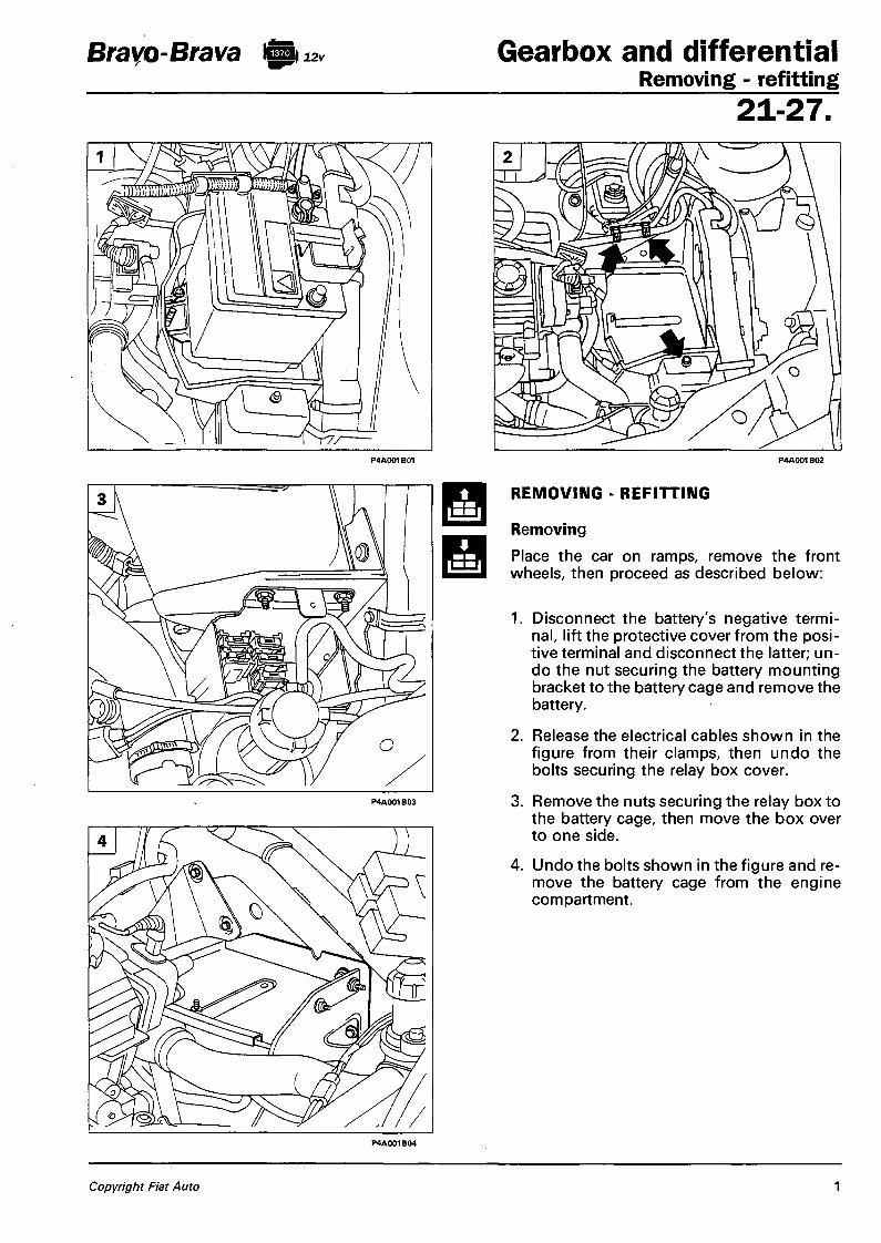
Bravo-Brava ft 12v Gearbox and differential Removing - refitting
2 1 - 2 7 .
REMOVING - REFITTING
Removing Place the car on ramps, remove the front wheels, then proceed as described below:
1. Disconnect the battery's negative terminal, lift the protective cover from the positive terminal and disconnect the latter; undo the nut securing the battery mounting bracket to the battery cage and remove the battery.
2. Release the electrical cables shown in the figure from their clamps, then undo the bolts securing the relay box cover.
3. Remove the nuts securing the relay box to the battery cage, then move the box over to one side.
4. Undo the bolts shown in the figure and remove the battery cage from the engine compartment.
Copyright Fiat Auto 1

Gearbox and differential Removing - refitting
Bravo-Brava I mm i2v
21-27 .
1. Disconnect the gear selector rod (1), disconnect the reversing lights switch (2), inhibition cable (3), earth cable (4) and clutch cable (5).
2. Disconnect the head of the gear engagement flexible transmission cable, disconnect the odometer connection then move the assembly aside in the engine compartment.
3. Undo the top bolts securing the starter motor to the gearbox.
4. Raise the ramps, undo the nut securing the steering tie-rod end, then using tool 1847038000 disconnect it from the vertical link. Repeat the procedure for the tie-rod end on the other side.
2 Publication no. 506.670
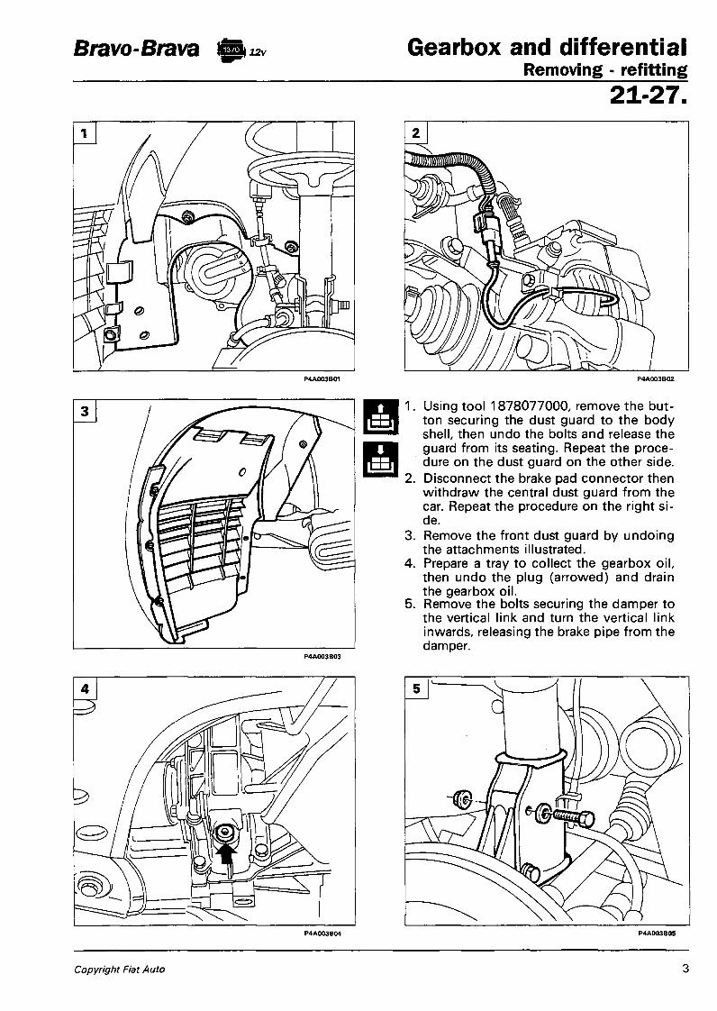
Bravo-Brava ft 12v Gearbox and differential Removing - refitting
2 1 - 2 7 .
3.
Using tool 1878077000, remove the button securing the dust guard to the body shell, then undo the bolts and release the guard from its seating. Repeat the procedure on the dust guard on the other side. Disconnect the brake pad connector then withdraw the central dust guard from the car. Repeat the procedure on the right side. Remove the front dust guard by undoing the attachments illustrated. Prepare a tray to collect the gearbox oil, then undo the plug (arrowed) and drain the gearbox oil. Remove the bolts securing the damper to the vertical link and turn the vertical link inwards, releasing the brake pipe from the damper.
Copyright Fiat Auto 3

Gearbox and differential Removing - refitting
Bravo-Brava I
21 -27 .
1. Disconnect the drive shaft, gearbox side, from the differential, levering on the engagement point, and move it away from the working area.
2. Disconnect the Lambda probe wiring connector.
3. Undo the nuts securing the first section of the exhaust pipe to the manifold.
4. Undo the rear attachments and remove the first section of the exhaust pipe from the car.
5. Disconnect the drive shaft, intermediate shaft side, from the differential, levering on the engagement point.
4 Publication no. 506.670

Bravo-Brava ft 12v Gearbox and differential Removing - refitting
2 1 - 2 7 .
1. Undo the bottom bolt securing the starter motor.
2. Disconnect the starter motor cables and disconnect the starter motor.
3. Remove the flywheel cover by undoing the bolts illustrated.
4. Remove the mounting bracket securing the first section of the exhaust pipe, to enable a spanner to be inserted to remove the bolt securing the gearbox to the engine.
5. Lower the ramps and remove the left windscreen wiper arm.
P4A005B05
Copyright Fiat Auto 5

Gearbox and differential Removing - refitting
Bravo-Brava ft 12v
21-27 .
1. Remove the plastic cover from the anti-pollen filter by undoing the screws illustrated.
2. Undo the top bolts securing the gearbox to the engine.
3. Fit the engine support stand 1860851000 on its mounting points.
a. Front mounting: insert the tool in the seat of the safety catch so that it rests on the front crossframe.
b. Rear mounting: position the tool level with the central reinforcement of the fire-proof bulkhead.
c. Secure the hook of the support stand to the inlet manifold so that it supports the power unit centrally.
P4A006B03
6 Publication no. 506.670

Bravo-Brava \12v Gearbox and differential Removing - refitting
2 1 - 2 7 .
1. Raise the car and disconnect the central power unit mounting from the bodywork and the gearbox.
2.3 Install the tool illustrated to support the gearbox during the removal operation.
4. Undo the remaining bolts securing the gearbox to the engine.
5. Remove the front power unit mounting, gearbox side, from the bodywork and the gearbox.
Copyright Fiat Auto 7

Gearbox and differential Removing - refitting
Bravo-Brava ft 12v
21-27.
<•>
Manoeuvre the jack as appropriate to release the gearbox from the centring studs, then remove the gearbox from the engine compartment by slowly lowering the hydraulic jack.
Refitting
Before refitting the gearbox-differential unit, check that the clutch release bearing has remained in the bellhousing and has not engaged with the clutch. Carry out the operations below:
2. Check that the clutch release bearing is positioned correctly on the gearbox main shaft.
Secure the clutch release lever, in the fully back position, to the bellhousing, then using the hydraulic jack bring the gearbox-differential unit to the clutch, centre ot in its references and secure it to the engine. For the subsequent operations, reverse the procedure for removal.
P4A008B03
8 Publication no. 506.670

Bravo-Brava I Gearbox and differential Drive shafts
21-27,
REMOVING - REFITTING
Place the car on ramps, disconnect the battery's negative terminal, remove the front wheels and then proceed as follows:
1. Using a hammer and chisel, relieve the staking on the hub nut.
2. Unscrew the hub nut.
3. Undo the bolt on the tie-rod end then use tool 1847038000 to disconnect the tie-rod.
4. Undo the bolts securing the vertical link to the damper, and angle the vertical link to release the shaft.
P4A003B05
Copyright Fiat Auto 9

Gearbox and differential Drive shafts
Bravo-Brava 112v
21 -27 .
1. Disconnect the drive shaft from the differential levering on the engagement point, then withdraw it from the car.
NOTE To refit, re verse the pro cedure for re -moval, tightening the hub nut to the specified torque.
DISMANTLING
2. Place the drive shaft in a vice, remove the protective gaiter from the joint on the gearbox side, then remove the joint.
3. Remove the circlip from the tripod joint and withdraw the joint from the drive shaft.
NOTE If the joint is damaged, it should be renewed.
4. Undo the clip on the protective gaiter on the gearbox side, then withdraw it from the drive shaft.
10 Publication no. 506.670

Bravo-Brava 12v Gearbox and differential Drive shafts
2 1 - 2 7 .
1. If interventions on the right drive shaft involve dismantling the damping weight, during reassembly refit the weight at the distance specified in the figure.
2. Undo the clips securing the protective gaiter on the constant velocity joint, wheel side, then withdraw it from the side opposite the drive shaft.
3. Clean the grease off the inside of the constant velocity joint, and using tools 1847017001 and 1860889000 simultaneously on the circlip inside the joint, remove the joint from the drive shaft.
4. Check that the drive shaft is not deformed or out of true, and that the seal contact surface is not worn.
Copyright Fiat Auto 11

Gearbox and differential Bravo-Brava ft** Drive shafts 21-27 .
REFITTING
1. Refit the protective gaiter on the wheel side and fit the constant velocity joint, applying appropriate pressure.
It is advisable to replace the protective gaiters whenever they are removed, and it is important to fill both constant velocity joint and gaiter with TUTELA MRM2 grease.
P4A012B01
Shaft-joint coupling on wheel side
Shaft classification
Joint classification
Categ. Colour Categ. Colour
A Blue A Blue
B White B White
B Red C Red
When refitting, the constant velocity joints must be coupled to the shaft as shown in the table. Category B joints are coupled with both categories of drive shaft; conduct a further check on the joint to make sure there are no signs of seizure or scoring.
2. Refit the protective gaiter on the gearbox side, fit the tripod joint securing it with the circlip, and then fit the joint on the gearbox side and secure the gaiter with its clips.
It is advisable to replace the protective gaiters whenever they are removed, and it is important to fill both joint and gaiter with TUTELA MRM2 grease.
P4A012B02
1 2 Publication no. 506.670

Bravo-Brava ft 12v Gearbox and differential Drive shafts
21-27 . DRIVE TRANSMISSION COMPONENTS
Key
1. Constant velocity joint wheel side 2. Circlip securing constant velocity joint 3. Protective gaiter 4. Drive shaft
5. Protective gaiter 6. Tripod joint 7. Circlip securing tripod joint 8. Joint, gearbox side (part not present on
1581 16V engine)
Copyright Fiat Auto 13

Gearbox and differential Bravo-Brava i ttn^ Remote control assembly 21-27 . DIAGRAM OF REMOTE CONTROL ASSEMBLY The Bravo-Brava with 137012venginehasaremotecontrolassemblysystemconsistingofarigidrod(3)and a flexible cable (4). The rigid rod (3) controls gear selection by means of a relay link (5); the flexible cable (4) instead controls gear engagement. There is also a safety device (7) for preventing accidental selection of reverse gear.
To operate this device, press the knob (1) of the gearlever downwards; this, by means of the flexible cable (2),lifts the pushrod of the device (7) which in turn permits the travel of the control shaft (6) for selecting reverse gear.
P4A014B01
Perspective view of remote control assembly with device for inhibiting accidental selection of reverse gear
1. Sliding part of gearlever 2. Flexible cable controlling device for inhibiting accidental selection of reverse gear 3. Rigid rod controlling gear selector link 4. Gear engagement flexible cable 5. Gear selector control link 6. Gear selector and engagement shaft 7. Device for inhibiting accidental selection of reverse gear
14 Publication no. 506.670

Bravo-Brava to 12v Gearbox and differential Remote control assembly
2 1 - 2 7 .
P4A015B02
REMOVING - REFITTING
Disconnect the battery's negative terminal, and remove the remote control assembly as described below:
1. From inside the car, remove the gearlever trim.
2. Remove the protective boot from the handbrake, then disconnect the electrical connection underneath.
3. Disconnect the gear engagement flexible transmission cable from the gearbox.
4. Disconnect the reverse gear inhibitor from the gearbox.
5. Remove the reaction and gear selector link from the gearbox.
Copyright Fiat Auto 15

Gearbox and differential Remote control assembly
Bravo-Brava !gn 12v
21-27 .
1. Raise the car, then disconnect the handbrake cables from the mounting and release them from the bracket.
2. After disconnecting the Lambda probe electrical connection, undo the bolts securing the first section of the exhaust pipe to the manifold.
3. Disconnect the first section of the exhaust pipe from the rear mountings.
4. Release the exhaust pipe from the rubber mount indicated.
5. Undo the bolts securing the exhaust pipe front mounting bracket.
16 Publication no. 506.670

Bravo-Brava lip 12v Gearbox and differential Remote control assembly
2 1 - 2 7 .
1. Undo the bolt securing the exhaust pipe rear bracket, then withdraw it from the car.
2. Remove the heat shield by undoing the bolts indicated.
3. Undo the front and rear bolts of the handbrake and remote control assembly mounting.
4. Carefully lower the assembly from its seating, and undo the nuts securing the remote control assembly to the gearlever mounting and remove it from the car.
Withdraw the cables and reaction rod from the engine compartment and withdraw the assembly from the car.
Copyright Fiat Auto 17
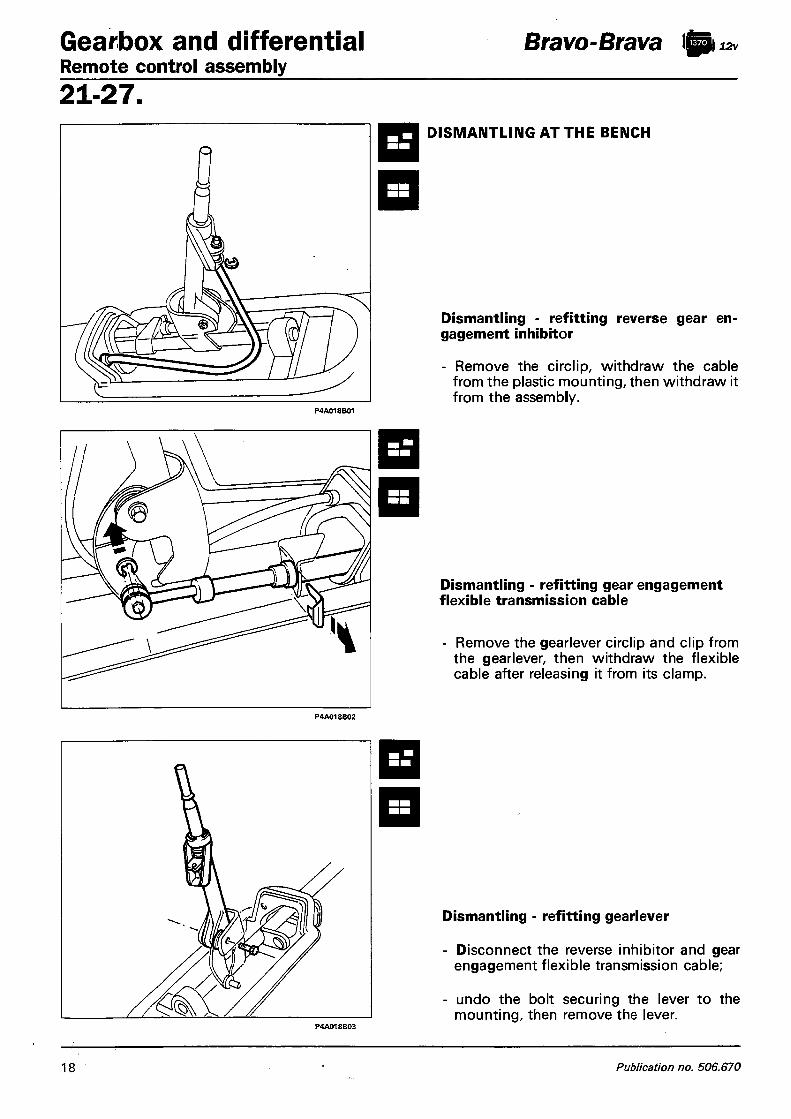
Gearbox and differential Remote control assembly
Bravo-Brava lg| 12v
21-27 . DISMANTLING AT THE BENCH
Dismantling - refitting reverse gear engagement inhibitor
- Remove the circlip, withdraw the cable from the plastic mounting, then withdraw it from the assembly.
Dismantling - refitting gear engagement flexible transmission cable
- Remove the gearlever circlip and clip from the gearlever, then withdraw the flexible cable after releasing it from its clamp.
Dismantling - refitting gearlever
- Disconnect the reverse inhibitor and gear engagement flexible transmission cable;
- undo the bolt securing the lever to the mounting, then remove the lever.
18 Publication no. 506.670

Bravo-Brava ft 12v Gearbox and differential Remote control assembly
2 1 - 2 7 .
Dismantling - refitting reaction link
- Remove the reverse gear inhibitor cable, the gear engagement flexible transmission cable and gearlever, then withdraw the reaction link.
REMOVING CAR
REFITTING GEARLEVER ON
- Remove the gearlever trim; - disconnect the reverse gear inhibitor cable
from the gearlever, after withdrawing the circlip.
- disconnect the flexible cable from the lever mounting, after r moving the circlip;
- undo the bolt securing the lever to the mounting, then remove it from the car.
- To refit, reverse the procedure for removal.
Copyright Fiat Auto 19
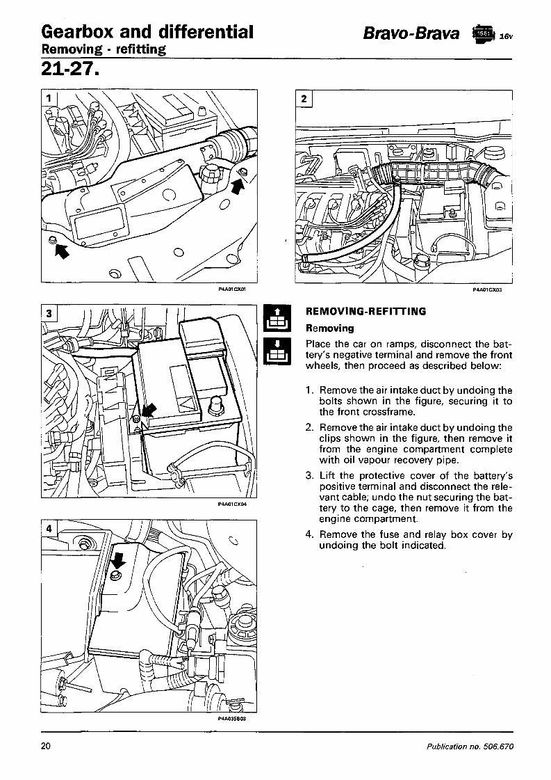
Gearbox and differential Bravo-Brava ft Removing - refitting 21 -27 .
P4A01CX01 P4A01CX03
REMOVING-REFITTING Removing Place the car on ramps, disconnect the battery's negative terminal and remove the front wheels, then proceed as described below:
1. Remove the air intake duct by undoing the bolts shown in the figure, securing it to the front crossframe.
2. Remove the air intake duct by undoing the clips shown in the figure, then remove it from the engine compartment complete with oil vapour recovery pipe.
3. Lift the protective cover of the battery's positive terminal and disconnect the relevant cable; undo the nut securing the battery to the cage, then remove it from the engine compartment.
4. Remove the fuse and relay box cover by undoing the bolt indicated.
P4A035B03
20 Publication no. 506.670

Bravo-Brava l&t 16v Gearbox and differential Removing - refitting
2 1 - 2 7 .
P4A02CX04
Remove the nuts securing the fuse and relay box to the battery cage, then move the box over to one side.
2. Disconnect the connector.
i.e. control unit supply
3. Remove the nuts securing the i.e. control unit mounting bracket, then remove the control unit from the engine compartment. The nuts indicated also secure the starter motor supply wiring and connection between the front cable and fuel injection cable.
4. Remove the bolts (1) and slacken the bolt (2) securing the battery cage to the bodywork. Before removing the cage, disconnect the cable clip underneath.
5. Disconnect the clutch cable by undoing the nut (1) and lock nut (2) shown in the figure. Also disconnect the earth cable (3) from the gearbox.
Copyright Fiat Auto 21

Gearbox and differential Removing - refitting
Bravo-Brava ft 16v
2 1 - 2 7 .
1. Disconnect the reaction link shown in the detail and the gear selector and engagement rods from the gearbox; also disconnect the speedometer sensor wiring connector.
2. Disconnect the reversing lights switch connector from the gearbox.
3. Remove the fan by undoing its attachment bolts, making sure to disconnect the supply connections (1).
4. Disconnect the starter motor supply cables.
5. Remove the starter motor by undoing the bolts shown in the figure.
22 Publication no. 506.670

Bravo-Brava Icpi 16v Gearbox and differential Removing - refitting
2 1 - 2 7 .
1
1. Remove the gearbox top bolts.
2. Fit an appropriate support eyelet at the point shown in the figure, to hook the power unit onto during removal of the gearbox.
3. Undo the nut securing the right windscreen wiper arm after removing the protective cap.
4. Remove the right side cover of the anti-pollen filter by undoing the bolts indicated, while the bolts securing the left cover must be slackened to allow the power unit support stand to be fitted.
Copyright Fiat Auto 23
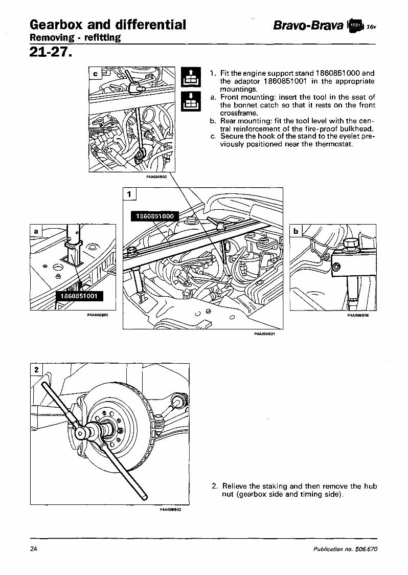
Gearbox and differential Removing - refitting
Bravo-Brava ft 16v
21-27 . Fit the engine support stand 1860851000 and the adaptor 1860851001 in the appropriate mountings. Front mounting: insert the tool in the seat of the bonnet catch so that it rests on the front crossframe. Rear mounting: fit the tool level with the central reinforcement of the fire-proof bulkhead. Secure the hook of the stand to the eyelet previously positioned near the thermostat.
2. Relieve the staking and then remove the hub nut (gearbox side and timing side).
24 Publication no. 506.670

Bravo-Brava S 16v Gearbox and differential Removing - refitting
2 1 - 2 7 .
1. Remove the plastic wheelarch protection on the gearbox by undoing the bolts and retaining button shown in the figure. To withdraw the protection, it is also necessary to disconnect the brake pad wear sensor connector (repeat the procedure on the other side).
2. Remove the nut securing the steering tie¬-rod end, then withdraw the latter from the vertical link arm using the puller 1847038000 (repeat the procedure for the other tie-rod end).
3. Remove the nuts securing the vertical link (gearbox and timing side) to the damper.
4. Rotate the vertical link as appropriate so as to withdraw the drive shaft from the wheel hub (repeat the operation for the other drive shaft).
P4A06CX02
Copyright Fiat Auto 25

Gearbox and differential Removing - refitting
Bravo-Brava ft 16v
21 -27 .
1. Undo the bolt (arrowed) on the bellhousing so that the gearbox support tool can be installed.
2-3. Place the gearbox support tool 1860873000 on a hydraulic jack, then secure it to the gearbox at the points indicated in the figure.
4. Remove the central power unit mounting by undoing the bolts shown in the figure.
5. Remove the cover shown in the figure from the bottom of the gearbox.
26 Publication no. 506.670

Bravo-Brava ft 16v Gearbox and differential Removing - refitting
2 1 - 2 7 .
1. Remove the engine mounting, gearbox side. 2. Remove the bottom bolts securing the
bellhousing to the engine block. 3. Remove the nuts securing the first section of
the exhaust pipe to the manifold, to enable the power unit to be moved forwards and so facilitate withdrawal of the gearbox. If this is still not sufficient, disconnect the coolant inlet and outlet pipes from the heater.
4. Manoeuvre the hydraulic jack as appropriate to disengage the gearbox from its attachment studs and the surrounding components. Gradually lower the jack and withdraw the gearbox complete with drive shafts.
5. If the gearbox is to be overhauled, drain the oil by undoing the plug (arrowed) and disconnect the two drive shafts, removing the gaiter retaining clips.
Copyright Fiat Auto 27

Gearbox and differential Drive shafts
Bravo-Brava «p 16v
21-27 .
1 o ft
n
1 —1 ~
Refitting When refitting the engine mounting on the gearbox side, to avoid creating stresses on the gearbox sealing surfaces resulting in deformation and oil leaks, strictly observe the following tightening sequence for the attachment bolts: - Lightly tighten bolts (1) and (2) to an ini
tial torque of 0.5 daNm; - Lightly tighten bolts (3) and (4) to an ini
tial torque of 0.5 daNm, then tighten to the specified torque;
- Tighten bolts (1) and (2) to the specified torque.
For the remaining refitting operations, reverse the procedure described for removal. For fitting the clutch release bearing and the bellhousing in the car, refer to the procedure for refitting the gearbox of the 1370 12v engine.
REMOVING-REFITTING DRIVE SHAFTS To remove and refit the drive shafts, refer to the procedure described for the 1370 12v engine, with the difference that the drive shafts are secured to the gearbox-differential unit by means of retaining clamps and the tripod joint is inserted directly in the differential.
DISMANTLING Refer to the dismantling of the drive shaft described for the 1370 12v engine, with the difference that on the 1581 engine, to minimise oil leaks, fluid-tight ball bearings have been fitted in the gaiters on the gearbox side. These are installed directly on the drive shafts. Use the general purpose puller to remove these bearings.
Position of damping weight on the right drive shaft If interventions on the right drive shaft involve dismantling the damping weight, during reassembly refit the weight at the distance specified in the figure. a = 290-295 mm or alternatively 292-297 mm
28 Publication no. 506.670

Bravo-Brava fti l e v Gearbox and differential Drive shafts
2 1 - 2 7 .
108mm 110mm« Right drive shaft
REFITTING Reverse the procedure described for removal. To refit the differential casing oil seal bearing, refer to the instructions below.
1. Refitting differential casing oil seal bearing.
• Alternative.
Fit and install the I NA seal bearing, for the differential casing oil seal gaiter, using the appropriate drift.
Fit and install the NARDELLA seal bearing, for the differential casing oil seal gaiter, using the appropriate drift. After assembly, the bearing should be in the position shown in the figure.
Copyright Fiat Auto 29

Bravo-Brava ft lev Gearbox and differential Remote control assembly 21-27
DIAGRAM OF REMOTE CONTROL ASSEMBLY
P4A03OBO1
Gear engagement and selector linkage
1. Gear selector rod mounting 2. Control rod 3. Relay mounting supporting gear engagement and selector linkage 4. Gear selector rod linkage 5. Gear engagement rod linkage 6. Reaction link 7. Bearings 8. Pin securing relay mounting supporting gear engagement and selector linkage
30 Publication no. 506.670

Bravo-Brava ft m i 6 v Gearbox and differential
Remote control assembly 2 1 - 2 7 .
REMOVING - REFITTING
Disconnect the battery's negative terminal, and dismantle the remote control assembly as described below:
1. Remove the gearlever trim from inside the car.
2. Undo the bolt securing the remote control assembly mounting to the bodywork.
3. Remove the handbrake lever trim and disconnect the electrical connection underneath.
4. Raise the ramps and disconnect the Lambda probe electrical connector.
5. Disconnect the handbrake cables from the mounting and release them from the bracket.
P4A016B02
Copyright Fiat Auto 31

Gearbox and differential Remote control assembly
Bravo-Brava A i 16v
21-27 .
1. Disconnect the Lambda probe electrical connection and disconnect the first section of the exhaust pipe from the front mountings.
2. Release the exhaust pipe from the rubber mount indicated.
3. Undo the bolts securing the exhaust pipe front mounting.
4. Undo the bolts securing the exhaust pipe rear mounting, then withdraw it from the car.
5. Remove the heat shield by undoing the bolts illustrated.
32 Publication no. 506.670

Bravo-Brava )Ai 16v Gearbox and differential Remote control assembly
2 1 - 2 7 .
1. Disconnect the gear engagement and selector rods and the reaction link, then undo the nut and disconnect the relay assembly from the control rod.
2. Undo the bolts securing the remote control assembly mounting and handbrake to the bodywork.
3. Withdraw the control rod from the engine compartment, then remove the gearbox remote control assembly.
4. Internal control assembly
Copyright Fiat Auto 33

Gearbox and differential Remote control assembly
Bravo-Brava ft 16v
21-27 . DISMANTLING AT THE BENCH
Dismantling - refitting gearlever
- Undo the bolts securing the gearlever to the mounting and the bolt securing the control rod to the gearlever, then disconnect it from the assembly.
Dismantling - refitting control rod
- Undo the bolt securing it to the gearlever, then disconnect the control rod from the assembly.
34 Publication no. 506.670

Bravo-Brava ft 16v Gearbox and differential Removing - refitting
2 1 - 2 7 .
REMOVING - REFITTING
Removing Place the car on ramps, disconnect the battery's negative terminal and remove the front wheels.
1. Remove the air inlet duct by undoing the bolts illustrated.
2. Lift the protective cover on the positive terminal, disconnect the positive terminal, then undo the nut securing the battery to the cage and remove the battery.
3. Disconnect the electrical connections indicated, unscrew the bolts from the bracket, then remove the complete inlet duct.
4. Undo the bolt indicated and remove the cover of the relay box.
Copyright Fiat Auto 35

Gearbox and differential Removing - refitting
Bravo-Brava ft miev
21-27 .
1. Undo the bolts securing the relay box to the battery cage, then move it over to one side.
2. Disconnect the cables indicated from the wiring on the battery's positive terminal.
3. Remove the screws (1) and slacken the bolt (2) securing the battery cage to the bodywork. Before removing the cage, disconnect the cable clip underneath.
4. Disconnect the clutch cable by undoing the nut (1) and locknut (2) shown in the figure. Also disconnect the earth cable (3) from the gearbox and the electrical connector for the reversing lights switch (4).
5. Disconnect the reaction link.
36 Publication no. 506.670

Bravo-Brava ft •Jit 16 v Gearbox and differential Removing - refitting
2 1 - 2 7 .
1. Disconnect the fan's supply c o n n e c tions. Undo the bolts securing it to the radiator, then remove it from the car.
2. Undo the top bolts securing the gearbox to the power unit.
3. Remove the engine reaction link.
4. Remove the left windscreen wiper arm by undoing the nut.
5. Remove the left side cover from the anti -pollen filter.
F — ^
Copyright Fiat Auto 37

Gearbox and differential Removing - refitting
Bravo-Brava ft 16v
3.
b.
c.
Disconnect the electrical connector of the odometer signal and the Lambda probe connector. Using two ordinary bolts, install a suitable supporting eyelet for hooking the power unit support stand. Fit the engine support stand 1860851000 and adaptor 1860851001 in the appropriate mountings. Front mounting: place the tool in the seat of the safety catch so that it rests on the front crossframe. Rear mounting: fit the tool level with the central reinforcement of the fire-proof bulkhead. secure the hook of the crossbeam to the previously secured bracket.
38 Publication no. 506.670

Bravo-Brava ft 16v Gearbox and differential Removing - refitting
2 1 - 2 7 .
5.
Using tool 1878077000, remove the button securing the dust guard to the bodywork, then undo the bolts and release the dust guard from its seating. Disconnect the brake pad connection then withdraw the central dust guard from the car. Remove the front dust guard by undoing the screws illustrated. Undo the nut securing the tie-rod end, then using tool 1847038000 disconnect the latter from the vertical link. Undo the vertical link bolts, then remove it.
Copyright Fiat Auto 3 9

Gearbox and differential Removing - refitting
Bravo-Brava fti
21 -27 .
Disconnect the drive shaft by undoing the bolts securing the constant velocity joint to the gearbox flange.
A Operations to be repeated on the other side
2. Disconnect the gear engagement and sector rods from the gearbox.
3. Raise the car and remove the front bolts securing the first section of the exhaust pipe.
4. Remove the rear bolts and remove the first section of the exhaust pipe from the car.
5. Remove the bracket indicated to permit insertion of a spanner to remove the bolt securing the gearbox to the power unit.
40 Publication no. 506.670

Bravo-Brava ft 16v Gearbox and differential Removing - refitting
2 1 - 2 7 .
1. Drain the gearbox oil, undoing the bolt indicated.
2. Undo the bolts securing the intermediate shaft to the engine, release it from the gearbox and move it away from the working area, securing it in an appropriate manner.
3. Remove the power unit's central mounting.
4. Remove the power unit mounting on the gearbox side.
5. Lower the car and manoeuvre the power unit as appropriate to make it perform the maximum permissible travel towards the front of the engine compartment.
Copyright Fiat Auto 4 1
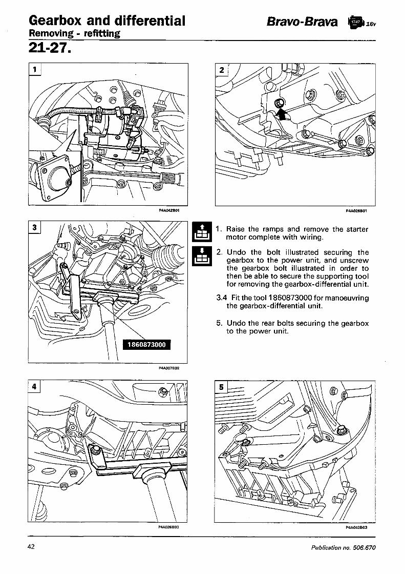
Gearbox and differential Removing - refitting
Bravo-Brava fti I l6v
21-27 .
1. Raise the ramps and remove the starter motor complete with wiring.
2. Undo the bolt illustrated securing the gearbox to the power unit, and unscrew the gearbox bolt illustrated in order to then be able to secure the supporting tool for removing the gearbox-differential unit.
3.4 Fit the tool 1860873000 for manoeuvring the gearbox-differential unit.
5. Undo the rear bolts securing the gearbox to the power unit.
42 Publication no. 506.670

Bravo-Brava fti 3 l i 6 v Gearbox and differential Drive shafts
2 1 - 2 7 .
<i> 1. Manoeuvre the hydraulic jack as appropriate to withdraw the gearbox from the centring studs, then withdraw the gearbox from the engine compartment, slowly lowering the jack.
Refitting 2. When refitting the engine mounting on
the gearbox side, in order to avoid creating stresses on the gearbox sealing surfaces resulting in deformation and oil leaks, strictly observe the following tightening sequence for the bolts:
- Lightly tighten bolts (1) and (2) to a torque of 0.5 daNm;
- Lightly tighten bolts (3) and (4) to a torque of 0.5 daNm, then tighten them to the specified torque;
- Tighten bolts (1) and (2) to the specified torque.
To refit, reverse the procedure described for removal.
REMOVING - REFITTING DRIVE SHAFTS Place the car on ramps, disconnect the battery's positive terminal and remove the front wheels, then carry out the operations described below: 3. Disconnect the drive shaft by undoing the
screws illustrated. 4. Withdraw the drive shaft from the wheel
hub and withdraw it from the engine compartment.
NOTE To refit, reverse the procedure for removal, tightening the hub nut to the specified torque.
Copyright Fiat Auto 4 3

Gearbox and differential Drive shafts
Bravo-Brava ft 16v
21-27 .
DISMANTLING 1. Remove the clip and the protective gaiter
on the constant velocity joint, wheel side. During assembly, it is advisable to replace the protective gaiter.
2. Clean the grease off the inside of the constant velocity joint and, using tools 1847017001 and 1860889000, remove the constant velocity joint and then withdraw the protective gaiter, previously moved aside, from the drive shaft.
3. Remove the protective cover from the constant velocity joint, gearbox side.
4. Remove the two clips securing the protective gaiter on the gearbox side, then remove it.
5. Clean the grease off the inside of the constant velocity joint and remove the circlip from its seating.
P4A044B04 P4A044B05
44 Publication no. 506.670
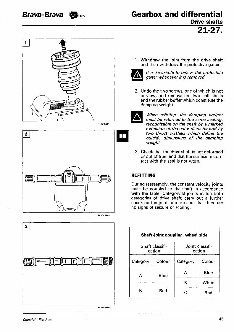
Bravo-Brava fti Ml6v Gearbox and differential Drive shafts
2 1 - 2 7 .
2
]
Withdraw the joint from the drive shaft and then withdraw the protective gaiter.
It is advisable to renew the protective gaiter whenever it is removed.
2. Undo the two screws, one of which is not in view, and remove the two half shells and the rubber buffer which constitute the damping weight.
When refitting, the damping weight must be returned to the same seating, recognizable on the shaft by a marked reduction of the outer diameter and by two thrust washers which define the outside dimensions of the damping weight.
3. Check that the drive shaft is not deformed or out of true, and that the surface in contact with the seal is not worn.
REFITTING
During reassembly, the constant velocity joints must be coupled to the shaft in accordance with the table. Category B joints match both categories of drive shaft; carry out a further check on the joint to make sure that there are no signs of seizure or scoring.
Shaft-joint coupling, wheel side
Shaft classification
Joint classification
Category Colour Category Colour
A Blue A Blue
A Blue
B White
B Red
B White
B Red C Red
Copyright Fiat Auto 45
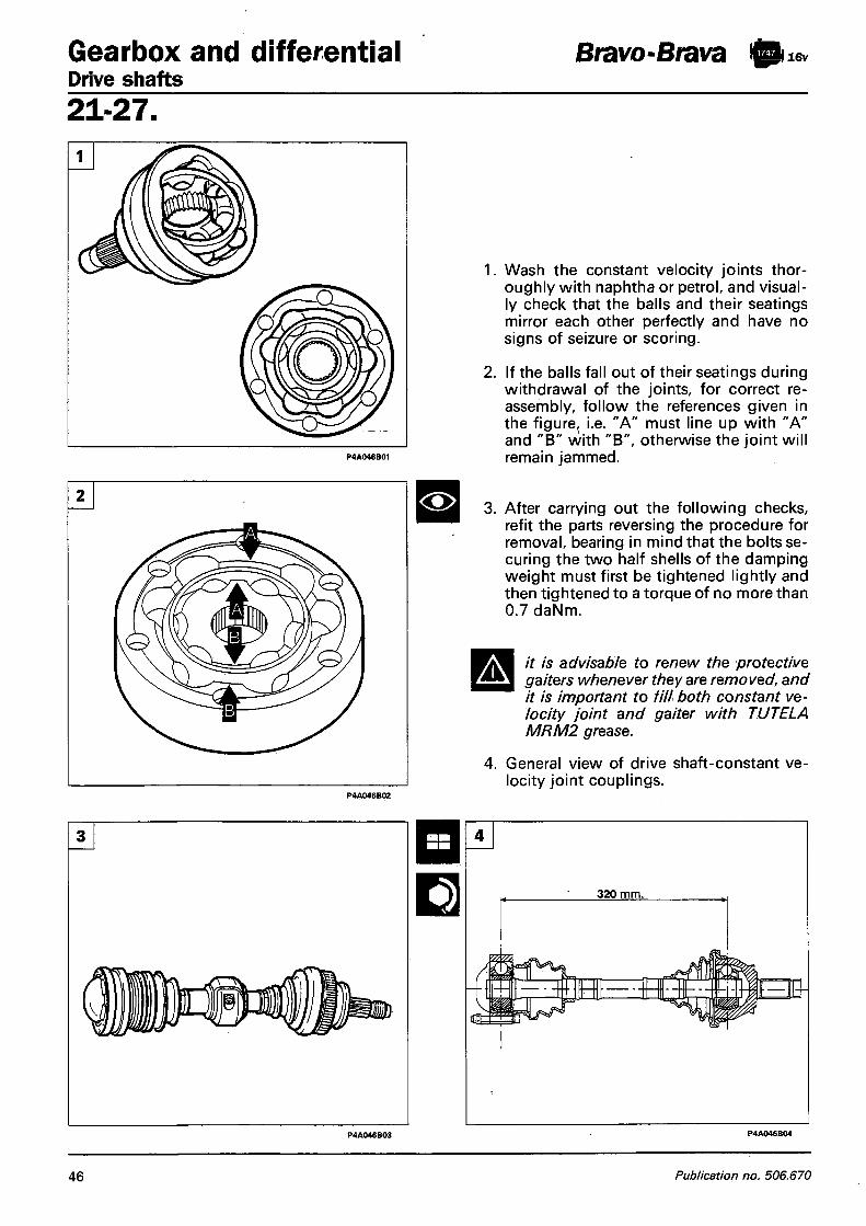
Gearbox and differential Drive shafts
Bravo-Brava ft 16v
21-27 .
<•>
Wash the constant velocity joints thoroughly with naphtha or petrol, and visually check that the balls and their seatings mirror each other perfectly and have no signs of seizure or scoring.
If the balls fall out of their seatings during withdrawal of the joints, for correct reassembly, follow the references given in the figure, i.e. "A" must line up with "A" and "B" with "B", otherwise the joint will remain jammed.
After carrying out the following checks, refit the parts reversing the procedure for removal, bearing in mind that the bolts securing the two half shells of the damping weight must first be tightened lightly and then tightened to a torque of no more than 0.7 daNm.
it is advisable to renew the protective gaiters whenever they are removed, and it is important to fill both constant velocity joint and gaiter with TUTELA MRM2 grease.
4. General view of drive shaft-constant velocity joint couplings.
46 Publication no. 506.670

Bravo-Brava ft 16v Gearbox and differential Drive shafts
Drive transmission components
2 1 - 2 7 .
1. Constant velocity joint, wheel side 2. Retaining clips 3. Rubber buffer 4. Damping half shells 5. Drive shaft
6. Protective gaiter 7. Flange for constant velocity joint, gearbox side 8. Constant velocity joint, gearbox side 9. Circlip
10. Protective cover
Copyright Fiat Auto 4 7

Gearbox and differential Intermediate shaft - Remote control assembly
Bravo-Brava ft lev
21-27 .
REMOVING - REFITTING
Place the car on ramps, remove the front right wheel, drain the gearbox oil and carry out the operations listed below, which have already been described above:
- Remove the right wheelarch cover - Disconnect the right tie-rod end - Disconnect the vertical link and drive shaft
from the joint. 1. Undo the bolts securing the intermediate
shaft to the mounting.
2. Withdraw the intermediate shaft from its seating, then remove the dust excluder.
3. Withdraw the intermediate shaft from the engine compartment.
4. Check that the intermediate shaft (1) is not deformed or out of true; check that the bearing (2) does not show signs of overheating, scoring or excessive wear.
NOTE The bearing is not supplied as a spare part, so if it is faulty, the complete intermediate shaft must be replaced.
REMOTE CONTROL ASSEMBLY
To remove and refit the remote control assembly, refer to the "Remote control assembly" section for the 1581 16v engine.
48 Publication no. 506.670

Bravo-Brava 1) 20V Gearbox and differential Removing-refitting
2 1 - 2 7 .
REMOVING-REFITTING Removing Place the car on ramps, disconnect the battery's negative terminal and the front wheels, then proceed as described below: 1. Remove the air intake duct by undoing the
bolts shown in the figure. 2. Disconnect the battery's positive terminal,
then remove the battery from the engine compartment by undoing the nut securing the retaining bracket.
3-4. Disconnect the pipe connecting the air cleaner to the throttle body by undoing the clips indicated, and disconnect the connections under the pipe; also remove the resonator.
5. Remove the relay box cover.
P4A035B03
Copyright Fiat Auto 49

Gearbox and differential Removing-refitting
Bravo-Brava ft 20v
21-27 .
4.
5.
Remove the nuts securing the relay box to the battery cage, then move it over to one side. Remove the battery cage by undoing the bolts shown in the figure; also disconnect the electrical wiring clips indicated. Disconnect the hydraulic clutch actuating cylinder from the gearbox, the earth cable and reversing lights switch. Disconnect the gear selector rod by removing the split pin shown in the figure. Also disconnect the speedometer sensor connection. Undo the nuts securing the cables shown in the figure to the battery's positive terminals.
P4A03DX04
50 Publication no. 506.670

Bravo-Brava ft l » 2 0 v Gearbox and differential Removing-refitting
2 1 - 2 7 .
P4A05DX04
1. Disconnect the Lamba probe connection.
2. Lift the protective cover, then remove the windscreen wiper arm by undoing its attachment nut.
3. Remove the right side cover from the anti-pollen filter; to facilitate removal, undo the screws of the left side cover.
4. Place a suitable supporting hook at the point shown in the figure, to hook the power unit on to during removal of the gearbox.
Copyright Fiat Auto 51

Gearbox and differential Removing-refitting
Bravo-Brava I) 20v
21-27 . 1. Position the engine support stand
1860851000 and adaptor 1860851001 in the mounting points.
Front mounting: insert the tool in the seat of the safety catch so that it rests on the front crossframe. Rear mounting: position the tool level with the central reinforcement of the fire-proof bulkhead. Secure the hook of the support stand to the eyelet previously fitted level with the thermostat.
2. Remove the gearbox top bolts.
P4A052B03
52 Publication no. 506.670

Bravo-Brava iggi 20v Gearbox and differential Removing-refitting
P4A04DX03
2 1 - 2 7 .
1. Remove the engine bay bottom guard. 2. Disconnect the first section of the exhaust
pipe by undoing the attachments shown in the figure.
3. Remove the wheelarch trim on the gearbox side and timing gear side.
4. Disconnect the tie-rod end from the vertical link (gearbox side and timing gear side) using the puller 1847038000.
5. Undo the bolts securing the left drive shaft flange.
Copyright Fiat Auto 53
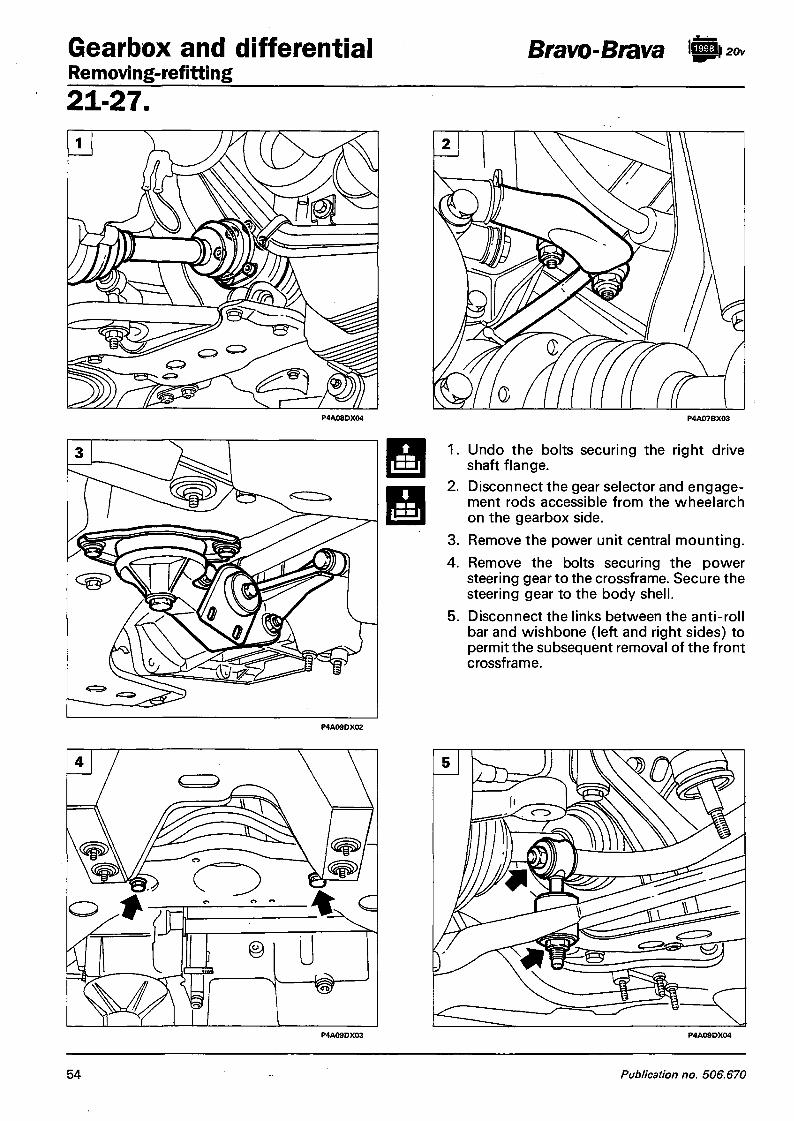
Gearbox and differential Removing-refitting
Bravo-Brava ft 20v
21-27 .
1. Undo the bolts securing the right drive shaft flange.
2. Disconnect the gear selector and engagement rods accessible from the wheelarch on the gearbox side.
3. Remove the power unit central mounting. 4. Remove the bolts securing the power
steering gear to the crossframe. Secure the steering gear to the body shell.
5. Disconnect the links between the anti-roll bar and wishbone (left and right sides) to permit the subsequent removal of the front crossframe.
54 Publication no. 506.670

Bravo-Brava S20v Gearbox and differential Removing-refitting
2 1 - 2 7 .
1. Undo the bolts securing the wishbone (right and left sides) to the front cross-frame; rotate the wishbone as appropriate to release it from the crossframe.
2. Remove the nuts shown in the figure on the heat shield to permit the subsequent withdrawal of the front crossframe. If necessary, shim the shield to keep it raised off the bodywork and so facilitate the withdrawal of the crossframe.
3. Undo the bolts securing the front cross-frame to the body shell; first remove the rear bolts and then the side bolts with the help of an assistant, and finally withdraw the crossframe complete with anti-roll bar.
Drain the gearbox oil then by undoing the plug shown in the figure.
Copyright Fiat Auto 55

Gearbox and differential Removing-refitting
Bravo-Brava b 20v
21-27 .
1. Undo the bolts securing the intermediate shaft to the engine, release it from the gearbox and move it away from the working area, securing it in an appropriate manner.
2. Remove the starter motor by undoing its bolts.
3. Remove the bottom bolts securing the gearbox to the power unit.
4. Undo the bolt shown in the figure from the bellhousing, to permit installation of the gearbox support tool.
5. Place the gearbox support tool 1860873000 on a hydraulic jack, then secure it to the gearbox as shown in the figure.
56 Publication no. 506.670

Bravo $ 20v Gearbox and differential Removing-refitting
2 1 - 2 7 .
1. Rear attachment of gearbox support tool 1860873000.
2. Remove the engine mounting, gearbox side. 3. Manoeuvre the hydraulic jack as appropri
ate in order to disengage the gearbox from the attachment studs and surrounding parts. Gradually lower the jack and withdraw the gearbox.
Refitting 4. When fitting the engine mounting, gear
box side, to avoid creating stresses on the sealing surfaces between the mounting and the gearbox, resulting in deformation and subsequent oil leak, closely follow the bolt tightening sequence below: - Tighten bolts (1) and (2) to a prelimi
nary torque di 0.5 daNm; - Tighten bolts (3) and (4) to a prelimi
nary torque of 0.5 daNm, then tighten to the specified torque;
- Tighten the bolts (1) and (2) to the specified torque.
For the remaining refitting operations, reverse the procedure described for removal. Before fitting the bellhousing in the car, check that the clutch release bearing is positioned correctly on the gearbox main-shaft.
A The oil level in the gearbox must be 9 mm below the oil filler plug hole.
Copyright Fiat Auto 57

Gearbox and differential Drive shafts - Remote control assembly
Bravo-Brava I) 20v
21-27 .
REMOVING-REFITTING TLING DRIVE SHAFTS
AND DISMAN-
To remove/refit and dismantle the drive shafts, refer to the procedure described for the 1747 16V engine, with the difference that drive shafts on the 1998 20V engine do not have the damping weight.
General view of drive shaft - constant velocity joint couplings and distance between the joint centres.
REMOVING-REFITTING INTERMEDIATE SHAFT
To remove and refit the intermediate shaft, refer to the instructions given for the 1747 16v engine.
REMOVING-REFITTING REMOTE CONTROL ASSEMBLY
To remove and refit the gearbox remote control assembly, refer to the instructions given for the 1581 16V engine.
58 Publication no. 506.670

Bravo-Brava ft Gearbox and differential Removing-refitting
2 1 - 2 7 .
REMOVING-REFITTING Place the car on ramps, disconnect the battery's negative terminal, remove the front wheels and then proceed as described below:
1. Disconnect air inlet duct by undoing the bolts shown in the figure, securing it to the front crossframe.
2. Remove the air inlet duct complete with resonator by undoing the clips shown in the figure, making sure to disconnect the pipe shown in the detail.
3. Lift the protective cover from the battery's positive pole and disconnect it, then remove the battery by undoing the nut and the attachment bracket shown in the figure. Also undo the nuts securing the cables shown in the detail, leading to the positive terminal.
4. Remove the fuse and relay box cover by undoing the bolt indicated.
Copyright Fiat Auto 59

Gearbox and differential Removing-refitting
Bravo-Brava fto
21 -27 .
1. Remove the nuts securing the fuse and relay box to the battery cage, then move the box over to one side.
2. Remove the battery cage by undoing the bolts shown in the figure; also undo the nuts securing the mounting bracket for the starter motor supply cables.
3. Disconnect the speedometer sensor connector.
4. Disconnect the clutch cable by undoing the nut ( 1 ) and locknut (2) shown in the figure. Also disconnect the earth lead (3) from the gearbox.
5. Disconnect the reaction link shown in the detail and the gear selector engagement rods from the gearbox.
P4A040B02
60 Publication no. 506.670
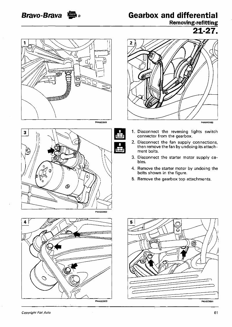
Bravo-Brava !SP o Gearbox and differential Removing-refitting
2 1 - 2 7 .
1. Disconnect the reversing lights switch connector from the gearbox.
2. Disconnect the fan supply connections, then remove the fan by undoing its attachment bolts.
3. Disconnect the starter motor supply cables.
4. Remove the starter motor by undoing the bolts shown in the figure.
5. Remove the gearbox top attachments.
Copyright Fiat Auto 61

Gearbox and differential Removing-refitting
Bravo-Brava | p °
21-27 .
Remove one exhaust manifold nut and fit a suitable hook for supporting the power unit during removal of the gearbox.
Remove the nut securing the right windscreen wiper arm after removing its protective cover.
Remove the right side cover from the anti-pollen filter by undoing the screws illustrated, and slacken the screws on the right side cover to allow the power unit support stand to be installed.
62 Publication no. 506.670

Bravo-Brava ft Gearbox and differential Removing-refitting
2 1 - 2 7 . Position the power unit support stand 1860851000 and the special adaptor 1860851001 in the appropriate mounting points. a. Front mounting: insert the tool in the
seating of the bonnet catch, so that it rests on the front crossframe.
b. Rear mounting: position the tool level to the central reinforcement of the fire-proof bulkhead.
c. Secure the hook of the stand to the eyelet previously installed level with the exhaust manifold attachments.
Relieve the staking and then remove the hub nut (gearbox side and timing gear side).
Copyright Fiat Auto 63

Gearbox and differential Removing-refitting
Bravo-Brava @ i o
21-27 .
3.
4.
Remove the plastic protection from the wheelarch on the gearbox side by undoing the bolts and the button shown in the figure. To withdraw the protection, also disconnect the brake pad wear sensor connection (repeat the procedure on the other side). Remove the nut securing the tie-rod end to the vertical link, then withdraw the tie¬-rod end from the vertical link arm using puller 1847038000 (repeat the procedure for the other tie-rod end). Remove the bolts securing the vertical link (gearbox side and timing gear side) to the damper. Rotate the vertical link as appropriate to withdraw the drive shaft from the wheel hub (repeat the procedure for the other drive shaft).
P4A06CX02
64 Publication no. 506.670

Bravo-Brava ft ° Gearbox and differential Removing-refitting
2 1 - 2 7 .
1. Remove the bottom flywheel guard from the bellhousing.
2. Undo the bolt shown in the figure on the bellhousing, to enable the gearbox support tool to be installed.
3. Remove the power unit central mounting to enable the gearbox support tool to be subsequently installed.
4-5. Place the gearbox support tool 1860873000 on the hydraulic jack, then secure it to the gearbox at the points shown in the figure (front view and rear view).
Copyright Fiat Auto 65

Gearbox and differential Removing-refitting
Bravo-Brava
21-27 .
1. Remove the engine mounting, gearbox side. 2. Remove the bottom bolts securing the
bellhousing to the engine block.
3. Manoeuvre the hydraulic jack to disengage the gearbox from the attachment studs and surrounding components. Gradually lower the jack and withdraw the gearbox complete with drive shafts. If this operation proves difficult, remove the attachments securing the first section of the exhaust pipe to the manifold, to allow the engine to move forwards and so facilitate withdrawal of the gearbox.
4. If the gearbox has to be overhauled, drain the oil by undoing the plug indicated, and disconnect the two drive shafts by removing the gaiter clips.
66 Publication no. 506.670

Bravo-Brava ft) Gearbox and differential Drive shafts - Remote control assembly
2 1 - 2 7 . Refitting When refitting the engine mounting on the gearbox side, to avoid creating stresses on the gearbox sealing surfaces resulting in deformation and oil leaks, strictly observe the following tightening sequence of the attachment bolts: - Lightly tighten bolts (1) and (2) to an ini
tial torque of 0.5 daNm; - Lightly tighten bolts (3) and (4) to an ini
tial torque of 0.5 daNm, then tighten them to the specified torque;
- Tighten bolts (1) and (2) to the specified torque. For the remaining refitting operations, reverse the procedure described for removal. To fit the clutch release bearing and bellhousing to the car, refer to the instructions for refitting the gearbox of the 1370 12V engine.
• alternative Left drive shaft 133 mm 135 mm •
J Jmm,
110mmi Right drive shaft alternative
REMOVING-REFITTING DRIVE SHAFTS To remove and refit the drive shafts, refer to the procedure described for the 1370 12V engine, with the difference that the drive shafts are secured to the gearbox-differential unit by retaining clips and the tripod joint is inserted directly in the differential.
DISMANTLING-REASSEMBLY Refer to the dismantling of the drive shaft described for the 1581 16V engine. To fit the differential casing oil sealing bearing, refer to the figure opposite.
P o s i t i o n o f d a m p i n g w e i g h t o n r ight dr ive shaft In the case of interventions on the r ight drive shaft w h i c h involve removing the damping we igh t , the latter should be refi t ted at the distance specified in the f igure.
a = 305-310 mm or alternatively 307-312 mm
Copyright Fiat Auto 67


Bravo ft 2 * Engine Index
BOSCH MOTRONIC M 2.10.4 M.P.I. INTEGRATED INJECTION/IGNITION S Y S T E M 1 - Introduction 1 - General description of the injection
system 1 - General description of the •• ignition
system 1 - System functions 2
S Y S T E M MANAGEMENT S T R A T E G I E S 3
- Adjustment of the injection times 3 - Adjustments of the ignition advances 3 - Checking cold starting 3 - Checking acceleration enrichment 3 - Fuel cut off during deceleration
(Cut-off) 3 - Checking engine idle speed management 4 - Limiting maximum number of revs (pro
tection outside of revs) 4 - Cheeking combustion via the Lambda sensor4 - Fuel vapour recovery . 5 - Checking detonation * 5 - Checking phase transformer 5 - Connection to climate control system 5 - System self-adjustment '• • 5 - Connection wim engine starting immo
bilizing device (Fiat CODE) 6 - Autodiagnosis 6 Diagram showing information entering/leaving control unit and injection/ignition system sensors/actuators 7 Diagram showing fuel supply circuit 8 Diagram showing air intake circuit 9 Diagram showing fuel anti-evaporation circuit 10 System for recirculating gases coming from the engine crankcase 11 Diagram showing engine exhaust assembly 12 Location of injection/ignition system components 13 Wiring diagram showing injection/ignition system 14 Connection of control unit/ignition coils and injectors ^ 15
FUSES, RELAYS AND EARTH " POINTS 16
INJECTION/IGNITION SYSTEM COMPONENTS 17 - I n j e c t i o n / i g n i t k M i system wiring 17 - Injection/ignitaon. system electronic
control unit 17
10. - Ignition coils 19 - Timing sensor 21 - Rpm and TDC sensor 22 - Detonation sensors 23 - Electric fuel pump . 24 - Fuel filter 25 .-: Fuel supply manifold and pressure
regulator 25 - Injectors 26 - Butterfly casing % 27 - Butterfly valve position sensor 28 - Engine idle speed actuator 29 - Air temperature sensor 30 - Flow meter 30 - Coolant temperature sensor 32 - Speedometer sensor 33 - Phase transformer ' 33 - Lambda sensor 35 - Charcoal filter and fuel vapour cut put
solenoid valve 36 - Inertia switch 37 - Multi'-purpose valve and safety and
ventilation valve 38
CHECKS/ADJUSTMENTS AND REPAIR OPERATIONS TO BOSCH MOTRONIC M 2.10.4 INJECTION/IGNITION SYSTEM APART FROM FAULT DIAGNOSIS WITH THE F IAT/LANCIA T E S T E R 38
- Adjustment of accelerator control cable 38
- Removing-refitting fuel manifold complete with injectors and pressure regulator . 39
- Checks on fuel supply circuit - 40¬- Checking engine idle speed 42 - Checking concentration of pollutant
emissions 42
DIAGNOSIS 43
- Detecting problems 43 - Memorizing the error and structure of
the errors memory . 43 - Classification of the defect 43 - Frequency counter 43 - Signalling the problem 43 - Cancelling the error 44 - Fault diagnosis with the Fiat/
Lancia Tester 44 - List of errors » 44 - Parameters displayed 45 - Active diagnosis ' 45 - Recovery 45 - Permanent memory 45
Copyright by Fiat Auto

Bravo | 2 0 v Engine Fuel system
10. BOSCH MOTRONIC M 2.10.4 M.P.I. INTEGRATED INJECTION/ IGNIT ION S Y S T E M Introduction The Bosch Motronic system fitted on the 1998 5 cylinder 20valve engine belongs to the category of digital, inductive discharge, static advance electronic ignition systems integrated with sequential, timed type electronic injection. This system has only one electronic control unit, a single set of wiring and one set of common sensors. Its function is to inject the exact quantity of petrol into the engine inlet manifold, upstream of the inlet valves, to mix with the air introduced into the cylinder so that the correct mixture strength is obtained.
The Motronic M 2.10.4 system ensures efficient operation making it possible to achieve optimum performance and fuel consumption and to reduce harmful emissions through a response to the different engine operating conditions.
General description of the injection system The essential conditions which always have to be satisfied in the preparation of the air/fuel mixture for the smooth running of ignition engines are basically two: 1. the metering (air/fuel ratio) should be kept as constant as possible and close to the stoichiometric
value, in order to ensure the rapid combustion required to prevent unnecessary fuel consumption; 2. the mixture should be composed of petrol vapours atomized as finely and as uniformly as possible in
In the Bosch Motronic M 2.10.4 system the injector nozzles carry out the task of atomizing the petrol into minute droplets. Since the absolute pressure of the air drawn may vary, it is necessary to adjust the quantity of petrol to be injected so as not to alter the weight ratio between the air and the petrol. The constancy of this ratio is obtained by varying the supply pressure of the fuel, by means of a regulator, according to the valueof the vacuum of the air in the inlet manifold, so that the difference between the two pressures is constant at all engine operating conditions.
As far as the optimum metering, on the other hand, is concerned, it is calculated according to the following measurements: - exact quantity of air drawn in by the flow meter (air flow meter); - engine rotation speed by means of the rpm sensor; - acceleration required by means of the butterfly valve position sensor; - temperature of the engine coolant by means of the sensor on the thermostat mounting; - measuring the oxygen content of the exhaust gases via the Lambda sensor.
This information is processed by a micro-processor in the injection/ignition electronic control unit which determines the basic injection time using values, obtained experimentally, which are stored in a special memory in the above mentioned control unit.
General description of the ignition system The ignition system is the static advance, inductive discharge type (i.e. without a high tension distributor) with power modules inside the electronic control unit. The system has a single coil for each spark plug; the advantages of this solution are:
- less electrical overloading - guarantee of constant discharge at each spark plug The electronic control unit memory contains the entire series of optimum advance values which the engine can adopt for its operating range according to the engine speed and load conditions.
the air.
Copyright by Fiat Auto 1

Engine Bravo ft** Fuel system 10. These values have been obtained experimentally, by means of a long series of practical tests carried out on prototypes at the engine test bench to identify the advances at which it is possible to achieve the best compromise between the conflicting requirements of maximum power and low consumption and harmful exhaust emissions. The optimum advance values have then been memorized in the system control unit. During the operation of the engine, the control unit is constantly informed of the engine speed and load conditions and, on this basis, it "selects" the advance value from its memory to strike the spark at the spark plug for the cylinder during the explosion stroke with the optimum advance. In addition the control unit corrects this value depending on further factors such as engine coolant temperature, intake air temperature, detonation and position of the butterfly valve, so that the ignition point is always optimum. The information required by the control unit to operate the single coils is transmitted by means of electrical signals emitted by the following sensors:
a. An rpm sensor which generates a single phase alternating signal, whose frequency indicates the engine rpm.
b. An air flow meter which, on the basis of the quantity of air drawn in by the engine, transforms this value into an electrical signal, sending it to the electronic control unit.
c. An air temperature sensor which transforms the value of the intake air temperature into an electrical signal, sending it to the electronic control unit.
d. Two detonation sensors which are positioned in the upper part of the crankcase, one between cylinders 1 and 2 and the other between cylinders 4 and 5, allowing the control unit to recognize the cylinder which is detonating (or is in the early stages of detonation) and to correct the ignition advance for the spark plug for the cylinder involved only.
e. A butterfly valve position sensor which transforms the angular value of the actual butterfly into an electrical signal allowing the control unit to recognize the conditions of minimum, partial or full load.
Functions of the system In addition to electronically controlling the moment of ignition and the air flow rate during idling in order to allow the engine to run smoothly when the environment parameters and the load conditions vary, the control unit must also control and manage the injection in such a way that the stoichiometric ratio (air/¬fuel) is always within the optimum values. The electronic control unit establishes the «time» for the injectors following a relatively simple rule which can be summed up as follows. Taking the physical characteristics of the fuel (viscosity and density) and the difference in pressure between the fuel and the pressure in the inlet manifold as constant, the quantity of fuel injected depends only on the «opening time» of the injector.
The functions carried out by the injection/ignition - adjusting the injection times; - adjusting ignition advances; - checking cold starting; - checking the enrichment during
acceleration; - fuel cut off during deceleration (Cut-off); - checking and managing engine idle speed; - limiting the maximum number of revs; - checking combustion via the Lambda sen
sor;
system are basically as follows: - fuel vapour recovery; - checking detonation - checking the phase transformer - connection with the climate control system
(where fitted); - self-adjustment of the system - connection with the engine starting immo
bilizing device (Fiat CODE) ; - autodiagnosis.
2 Print no. 506.670

Bravo Engine Fuel system
10. S Y S T E M MANAGEMENT S T R A T E G I E S
Adjustment of the injection times Digital technology has made it possible to obtain optimum fuel consumption and performance by using programmed maps, stored inside the electronic control unit memory, dependent on the engine speed and load conditions. The control unit controls the injectors with extreme speed and precision, calculating the opening time on the basis of the load on the engine (number of revs and air flow rate) also taking into account the battery voltage and the temperature of the engine coolant. The injection is sequential and timed for each cylinder (the moment of injection is not simultaneous for all the cylinders) and takes place corresponding to the optimum injection point.
Adjustment of ignition advances
Thanks to a map memorized inside the electronic control unit it is capable of calculating the advance according to the engine load (minimum, partial, full, on the basis of the number of revs and air flow rate), the temperature of the intake air and the temperature of the engine coolant. It is possible to delay the ignition selectively for the cylinder requiring it, which can be recognized via the combination of the values recorded by the detonation and cam angle sensors.
Checking cold starting Under these circumstances there is a natural weakening of the mixture as a result of the poor turbulence of the particles of fuel at low temperatures, reduced evaporation and condensation on the inner walls of the inlet manifold, all of it exacerbated by the increased viscosity of the lubrication oil. The electronic control unit recognizes this condition and corrects the injection time on the basis of the coolant temperature signal, the temperature of the intake air, the battery voltage and the engine speed. The ignition advance is only dependent on the number of revs and the temperature of the engine coolant. During starting the control unit controls an initial simultaneous injection for all the injectors (full-group injection) and after the reference on the flywheel is recognized, it switches to the normal sequential timed operation. Whilst the engine is warming up, the electronic control unit controls the idle speed actuator which determines the quantity of air required to ensure that the engine does not cut out. The rotation speed is made to decrease proportionally as the temperature increases until the nominal value is obtained when the engine has reached operating temperature.
Checking acceleration enrichment When there is a request for acceleration, if the air flow meter signal variation exceeds a pre-set increase, the control unit not only adjusts the injection to the new requirements, but also increases it further through rapidly reaching the speed required.
When approaching the pre-set speed, the injection increase is gradually eliminated.
NOTE The request for acceleration is also detected by the potentiometer on the butterfly; this makes it possible to ensure optimum running if there is a failure in the air flow meter until a Service Dealer can be reached.
Fuel cut off during deceleration The fuel cut off during deceleration is the modified type. When the closed butterfly condition is recognized and the engine speed is greater than 1700 rpm (for engine speeds below 1700 rpm the cut off function is not operational to maintain optimum "driveabili-ty") the injection of fuel is deactivated. With no fuel supply, the engine speed starts to decrease more or less quickly depending on the vehicle driving conditions.
Copyright by Fiat Auto 3

Engine Bravo igp 2 0 v Fuel system 10. Before the idle speed is reached the dynamics of the engine speed decrease are checked.
If they exceed a certain value, the fuel supply is partly reactivated on the basis of a logic which involves the "soft accompaniment" of the engine at idle speed. When this condition is reached the normal idle functions are reactivated and the cut off during deceleration is only reactivated if the fuel cut off level is exceeded to ensure that the engine runs smoothly. The levels at which the fuel supply is restored and the cut off activated depend on the temperature of the engine. Another fuel cut off logic is developed in the engine which intervenes during partial deceleration, i.e. when lower engine loads are required. The function is only activated if the new condition persists for a pre-set time and after the ignition advance angle has been adjusted to the new situation.
Checking and managing engine idle speed
The adjustment of the idle speed is controlled in all operating conditions by means of the idle speed actuator which acts on the butterflyl by-pass. In addition to controlling the actual idle speed it also carries out the functions of a supplementary air valve and regulator for switching on the various consumers (e.g. the climate control compressor); with the butterfly in the end of travel position, in effect the actuator regulates the by-pass opening compensating for the power required by the consumers to ensure an engine idle speed of 750 rpm. The actuator fitted on this version guarantees great responsiveness to adjustment because the opening and the closing of the by-pass are both operated by magnetic windings. The correction of the idle is carried out not only by the actuator but also by the adjustment of the ignition (advance) angle because it has a more rapid effect.
NOTE The self-adjustment function makes it possible to dispense with all idle speed adjustments with the butterfly casing sensor recognizing the "butterfly in the end of travel" position and correcting any wear which occurs in time and is detected by the butterfly closure position.
Limiting maximum number of revs (protection outside of revs) When the engine speed exceeds 6,800 rpm, the electronic control unit reduces the injector operating times so that this value is not exceeded.
If the engine speed exceeds 7,013 rpm, the control unit activates the "fuel cut off" strategy restoring the operation of the injectors when the speed goes below 6,800 rpm.
Checking combustion via the Lambda sensor
The Lambda sensor informs the control unit of the quantity of oxygen present at the exhaust and therefore the correct air/fuel metering.
The optimum mixture is obtained with a Lambda coefficient of 1 (optimum stoichiometric mixture). The electrical signal which the sensor sends to the control unit undergoes a sharp variation when the composition of the mixture differs from Lambda= 1. When the mixture is "lean" (^>1) the control unit increases the quantity of fuel, when the mixture is "rich" ( k < 1) it decreases it: in this way the engine operates as close as possible to the ideal Lambda value.
The Lambda sensor signal is processed, inside the control unit, by a special integrator which prevents sharp variations in the injection times to correct the mixture strength.
The sensor is heated by an electrical resistance in order to be able to reach the correct operating temperature of around 300 °C rapidly.
By using this sensor it is possible to regulate the engine carburation with precision. This makes it possible, amongst other things, to operate at the limits laid down for emissions.
4 Print no. 506.670

Bravo $ 2 * Engine Fuel system
Fuel vapour recovery
The (pollutant in terms of the regulations) fuel vapours are sent to an active charcoal filter and from there towards the engine where they are burnt; this takes places by means of a solenoid valve which is operated by the control unit only when the engine is in a load condition which allows the correct combustion without the operation of the engine being "disturbed": in effect, the control unit compensates for this quantity of petrol entering with a reduction of the supply to the injectors.
Checking detonation
The function has the task of detecting the presence of the phenomenon of detonation (engine knocking) by processing the signal coming from the relevant sensors. The control unit constantly compares the signals coming from the sensors with a threshold value which, in turn, is continuously updated, to take into account background noise and the ageing of the engine. The control unit is therefore capable of detecting detonation (or the early stages of detonation) and makes provisions to reduce the ignition advance (from 3° up to maximum of 9.7°), until the phenomenon disappears. Afterwards the advance is gradually restored until the basic value is reached.
In acceleration conditions, a higher threshold is used, to take into account the greater noise produced by the engine in these circumstances. The detonation control strategy is also equipped with a self-adjustment function which ensures the memorizing of the advance reductions which should be constantly repeated to adapt to the different conditions in which the engine finds itself.
Checking phase transformer
The control unit controls the solenoid valve which controls the phase transformer depending on the engine load conditions. When the temperature of the coolant exceeds 40 °C and when the engine speed is higher than the idle speed and lower than 4,800 rpm with the butterfly angle greater than about 8°, the control unit sends a signal to the solenoid valve which is activated and allows the transformer to decrease the timing diagram for the inlet stage by 18° (torque operation).
When the engine is idling or the speed exceeds 4,800 rpm, the control unit deactivates the solenoid valve and the transformer restores the inlet timing to the previous basic values.
Obviously the control of the phase transformer operates with a hysteris field, i.e. the activating level for the solenoid valve is always higher than the deactivating level; this is designed to prevent balance conditions and a consequent too rapid succession passing from one timing diagram to another with obvious operating problems.
Connection with the climate control system
When the climate control is switched on the compressor absorbs power from the engine which, when idling, tends to cut out. To prevent this problem the control unit adjusts the air flow rate to the new power requirements, controlled by the appropriate actuator (this adjustment also takes place during usage conditions to maintain optimum "driveability"). Another function of the system is that of momentarily interrupting the supply to the compressor in the case of high power requirements by the engine (strong acceleration).
System self-adjustment
The control unit is equipped with a self-adjustment function which has the task of recognizing the changes which take place in the engine due to the settling processes which take place over a period of time and the ageing of both the components and the engine itself.
These changes are stored in the memory in the form of modifications to the basic map and have the task of adpating the operation of the system to the gradual alterations to the engine and the components in relation to the characteristics when new.
Copyright by Fiat Auto 5

Engine Bravo i 20v
Fuel system 10. This self-adjustment function also makes it possible to compensate for the inevitable differences (due to production tolerances) of any components which may have been replaced. This allows the best possible results for all vehicles with special adjustment or checking operations.
The self-adjustment parameters are lost if the control unit is disconnected.
Connection with engine starting immobilizing device (Fiat CODE) To increase protection against theft attempts, the vehicle has been equipped with an engine immobilizing device (Fiat CODE) which only allows the activation of the injection/ignition control unit by means of an electronic code. Each time the key is turned to the OFF position, the Fiat CODE system completely deactivates the injection/ignition control unit. When the ignition key is turned from the OFF position to the ON position the following operations take place in the order given: 1. The injection/ignition control unit sends the Fiat CODE control unit a request for the secret code in
order to deactivate the functions lock. 2. The Fiat CODE control unit responds by sending the secret code only after it, in turn, has received the
recognition code transmitted by the ignition key, which contains a special transponder inside. 3. The recognition of the secret code allows the de-activation of the functions lock and the injection/ig
nition control unit can activate the normal system management programme.
A special two directional serial line allows the exchange of information between the injection/ignition control unit and the Fiat CODE control unit. If there is a failure in the Fiat CODE system it is, however, still possible to start the engine via an emergency procedure.
Control units must not, under any circumstances, be exchanged between different vehicles to check if they are working properly.
• • • • During the fault diagnosis, before replacing the control unit, make sure that it really is not working properly, because when a new control unit is supplied the secret code is memorized making it completely unusable on other vehicles.
Autodiagnosis The Motronic M 2.10.4 injection/ignition system is also equipped with an "autodiagnosis" function which memorizes any problems with the sensors and actuators, making it easier to detect and correct them. Any problem is signalled by the appropriate warning light in the instrument panel.
6 Print no. 506.670
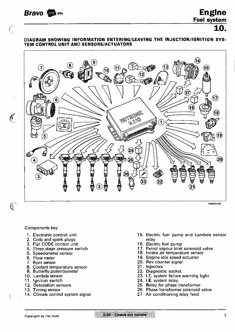
Bravo ft** E n g i n e Fuel system
10. DIAGRAM SHOWING INFORMATION ENTERING/LEAVING THE INJECTION/IGNITION S Y S TEM CONTROL UNIT AND SENSORS/ACTUATORS
P4A07FJ02
Components key
1. Electronic control unit 15. Electric fuel pump and Lambda sensor 2. Coils and spark plugs relay 3. Fiat CODE control unit 16. Electric fuel pump 4. Three stage pressure switch 17. Petrol vapour inlet solenoid valve 5. Speedometer sensor 18. Intake air temperature sensor 6. Flow meter 19. Engine idle speed actuator 7. Rpm sensor 20. Rev counter signal 8. Coolant temperature sensor 21. Injectors 9. Butterfly potentiometer 22. Diagnostic socket
10. Lambda sensor 23. I.E. system failure warning light 11. Ignition switch 24. I.E. system relay. 12. Detonation sensors 25. Relay for phase transformer 13. Timing sensor 26. Phase transformer solenoid valve 14. Climate control system signal 27. Air conditioning relay feed
Copyright by Fiat Auto X-96 - Cancels and replaces 7

Engine Fuel system
10. DIAGRAM SHOWING FUEL SUPPLY CIRCUIT
Bravo ft 20v
1. Fuel supply manifold 2. Supply pipe from the tank to the filter 3. Filter 4. Supply pipe from filter to injectors 5. Return pipe 6. Breather pipe 7. Filler with ventilation and safety valve 8. Tank 9. Electric pump
10 . Pressure regulator 11 . Injectors
NOTE Given the special shape of the tank, when fuel is being introduced an air pocket tends to form in the lower part preventing it from being filled completely; the pipe (6) allows the air to flow from the bottom thereby enabling the tank to be filled completely.
8 Print no. 506.660/10

Bravo U 20v Engine Fuel system
10. DIAGRAM SHOWING AIR INTAKE CIRCUIT
1. Inlet manifold 2. Engine idle speed actuator 3. Butterfly casing 4. Butterfly valve position sensor 5. Air temperature sensor
6. Flow meter 7. Air filter 8. Lower resonator 9. Upper resonator
10. Inlet opening
Copyright by Fiat Auto 9

Engine Bravo ft 2 0 v
Fuel system 10. DIAGRAM SHOWING FUEL ANTI-EVAPORATION CIRCUIT
P4A10FJ01
The anti-evaporation system has the task of preventing the fuel vapours, made up of the lightest sections of hydrocarbons which form in the tank, from being discharged into the atmosphere.
1. Fuel vapour cut out valve
2. Charcoal filter 3. Injection/ignition control unit
4. Safety and ventilation valve
5. Multi-purpose valve 6. Tank 7. Inlet manifold 8. Fuel vapour intake
10 Print no. 506.670

Bravo ft Engine Fuel system
10. S Y S T E M FOR RECIRCULATING G A S E S COMING FROM THE ENGINE C R A N K C A S E This system controls the emissions, from the engine crankcase, of breather gases made up of air/petrol mixtures and burnt gases which escape from the piston seals, in addition to lubricant oil vapours, recirculating them to the inlet. The breather gases, directedd by special walls, rise by the engine oil filler and then pass through the labyrinth (7), under the tappet cover, where they lose part of the oil which they contain, in the form of droplets, falling on the camshafts through the pipe (6). The siphon shape of the pipe (6) prevents the breather gases from escaping and only allows the recirculation of the droplets of oil. The remaining gases escape from the intake (5) inside of which there is a spark out (4) (to prevent the phenomenon of combustion due to flame returns from the butterfly casing). From the intake (5) the breather gases reach the T union (3). With the butterfly open, the gases flow through the intakes (1) and (2) to be drawn into the manifold. With the butterfly closed, the vacuum in the inlet manifold draws in the gases through the intake (1) which contains a PVC restricting valve (8) (Positive Crank Ventilation) which shutters the intake. The PCV valve can, in effect, be modulated and the quantity of gas which passes through is proportional to the vacuum in the inlet manifold. When the butterfly valve is completely open (condition A) , the vacuum inside the inlet manifold is minimal, the spring (10) is fully extended and the PCV valve allows the maximum flow of breather gases. Viceversa, with the butterfly completely closed (condition B) , the vacuum inside the manifold is maximum, this causes the movement of the piston (9) which shutters the section through which the breather gases flow inside the PCV valve thereby restricting the intake of the actual gases in the manifold.
A
P4A11FJ01
Copyright by Fiat Auto 11

Engine Bravo igiuov Fuel system 10. DIAGRAM SHOWING ENGINE EXHAUST ASSEMBLY
P4A12FJ01
Key
1. Exhaust manifold 2. Lambda sensor 3. Catalytic silencer 4. Silencers
12 Print no. 506.670

Bravo fti20v Engine Fuel system
10. LOCATION OF INJECTION/IGNITION SYSTEM COMPONENTS
P4A13FJ01
Key
1. Charcoal filter 12. Air temperature sensor 2. Fuel vapour solenoid valve connection 13. Vehicle speed sensor 3. Injection/ignition control unit 14. Lambda sensor 4. Fuses and relays 15. Join between front cable and injection 5. Diagnostic socket cabte
6. Injectors 16. Coolant temperature sensor
7. Rpm sensor 17. Earth connection
8. Engine idle speed actuator 18. Ignition coils
9. Butterfly valve position sensor 19. Timing sensor
10. General system protective fuse 20. Detonation sensor
11. Flow meter 21. Phase transformer solenoid valve 22. Fuel vapour solenoid valve
Copyright by Fiat Auto 13

Engine Bravo Fuel system 10. WIRING DIAGRAM SHOWING INJECTION/IGNITION SYSTEM
P4A14FJ01
14 Print no. 506.670

Bravo B20v Engine Fuel system
10. Connection of control unit/ignition coils and injectors
Key:
1. Rev counter signal 2. Climate control relay 3. Climate control on button 4. Fiat/Lancia Tester diagnostic sock
et 5. Fiat CODE control unit 6. Speedometer signal 7. Rpm and TDC sensor 8. Detonation sensor 1 9. Detonation sensor 2
10. Water temperature sensor 11. Timing sensor 12. Butterfly valve position sensor 13. Intake air temperature sensor 14. Three stage pressure switch 15. Ignition switch 16. I.E. system failure warning light 17. Flow meter 18. Phase transformer solenoid valve
relay 19. Engine idle speed actuator 20. Phase transformer solenoid valve 21. I.E. system relay feed 22. Fuel vapour solenoid valve 23. Battery 24. Electric fuel pump relay and
Lambda sensor 25. Inertia switch 26. Electric fuel pump 27. Lambda sensor 28. Injector for cylinder N°1 29. Injector for cylinder N°2 30. Injector for cylinder IM°3 31. Injector for cylinder N°4 32. Injector for cylinder N°5 33. Ignition coil for cylinder N°1 34. Ignition coil for cylinder N°2 35. Ignition coil for cylinder N°3 36. Ignition coil for cylinder N°4 37. Ignition coil for cylinder N°5
Copyright by Fiat Auto 15

Engine Fuel system 10 .
Bravo y 20v
FUSES, RELAYS AND EARTH POINTS
1. General protective fuse The genera! protective fuse (EFI-30A) for the injection/ignition system (1) is housed inside a container; to gain access to it, remove the cover releasing the side clips.
2. Fuses and relays
These are located under the glove compartment, in front of the electronic control unit.
1. Phase transformer solenoid valve relay 2. Injection system relay 3. Electric fuel pump relay 4. Lambda sensor fuse (10A) 5. Electric fuel pump fuse (10A)
3-4 Earth points
In order to improve electro-magnetic compatibility and operational reliability special care has been taken over the number and location of the earth points:
3. secondary coils connected below the cylinder head cover;
4. earth control unit (pin 2, 14, 19, 24,42), Lambda sensor heater, flow meter and phase transformer solenoid valve connected to the inlet manifold mounting bracket.
16 Print no. 506.670

Btavo !5Pi 20v Engine Fuel system
10. INJECTION/IGNITION SYSTEM COMPONENTS
The injection/ignition system is basically made up of wiring, an electronic control unit (I.E. control unit) and the following sensors/actuators:
Sensors
- Speedometer sensor
- Rpm and T.D.C. sensor
- Detonation sensors
- Coolant temperature sensor
- Timing sensor
- Butterfly valve position sensor
- Intake air temperature sensor
- Intake air flow rate sensor (flow meter)
- Lambda sensor
Actuators
- Engine idle speed actuator
- Phase transformer solenoid valve
- Fuel vapour cut out solenoid valve
- Electric fuel pump
- Injectors
- Ignition coils
- Spark plugs
INJECTION/IGNITION SYSTEM WIRING
The connection between the different system components is achieved by means of a single set of wiring with various type connectors grouped together in special conduits fitted on the engine.
INJECTION/IGNITION ELECTRONIC CONTROL UNIT
It is made up of thick film hybrid circuits and is connected to the electrical wiring by means of a 55 w a y (or pole) multiple connector.
All the information on the engine operating conditions transmitted by the various sensors flows into the control unit. By means of this data and with the aid of characteristic programmes written indelibly in its memory, the control unit is capable of achieving the following objectives:
1. Managing the injection time and frequency; in other words, it provides the quantity of fuel calculated for each cylinder with a sequential, timed operation (1 -2-4-5-3) . In practice, the air/fuel ratio should always remain within the optimum value, defined during setting up, in order to limit fuel consumption, reduce harmful exhaust emissions and ensure optimum thermodynamic efficiency for the engine.
2. Electronically controlling the moment of ignition (ignition advance)
3. Controlling the air flow rate at the rotation speed through the specific sensor in order to allow the smooth running of the engine as the environmental parameters and loads applied vary.
4. Detecting, by carrying out the programmes, any operating defects for the different sensors recorded in the RAM and replacing the incorect data or data not received with replacement values to ensure the operation of the engine even in emergency conditions (RECOVERY) .
5. Supplying the Fiat/Lancia Tester, if connected, via the serial line (diagnostic socket) with the data relating to the operating defects detected and memorized.
Copyright by Fiat Auto 17

Engine Bravo ft** Fuel system 10. IDENTIFICATION OF CONTROL UNIT CONNECTIONS (PIN-OUT)
P4A18FJ01
1. Ignition coil for cylinder N°1 2. Engine earth 3. Electric fuel pump relay feed and Lambda
sensor 4. Engine idle speed actuator 5. Fuel vapour solenoid valve 6. Rev counter signal 7. Intake air flow meter 8. Timing sensor 9. Speedometer sensor
10. Lambda sensor 11. Detonation sensor 12. Timing sensor 13. Not connected 14. Engine earth 15. Injector for cylinder N°3 16. Injector for cylinder N°2 17. Injector for cylinder N°1 18. Supply (+30) 19. Engine earth 20. Ignition coil for cylinder N°2 21. Ignition coil for cylinder N°4 22. Engine idle speed actuator 23. Not connected 24. Engine earth 25. Not connected 26. Not connected 27. Supply ( + 15/54) 28. Lambda sensor
29. Detonation sensor 30. Supply for various sensors 31. Not connected 32. Climate control go ahead relay 33. Not connected 34. Injector for cylinder N°5 35. Injector for cylinder N°4 36. I.E. system relay 37. Supply (+) 38. Ignition coil for cylinder N°5 39. Ignition coil for cylinder N°3 40. Three stage pressure switch 41. Air conditioning on signal 42. Engine earth 43. Not connected 44. Not connected 45. Coolant temperature sensor 46. Not connected 47. Fiat CODE control unit 48. Rpm and TDC sensor 49. Rpm and TDC sensor 50. Not connected 51. I.E. system failure warning light 52. Phase transformer solenoid valve relay 53. Butterfly valve position sensor 54. Intake air temperature sensor 55. Diagnostic socket for Fiat/Lancia Tester
18 VI-96 - Cancels and replaces Print no. 506.670/07

Bravo ft 20v Engine Fuel system
10. E L E C T R O N -R E M O V I N G - R E F I T T I I M G
I C C O N T R O L U N I T The electronic control unit is located under the glove compartment (right hand side). To remove the control unit proceed as follows: - Undo the bolts fixing the control unit to the
mounting bracket. - To remove the multiple connector, pull the
connector clip upwards.
A There could be tension at the terminals not connected therefore no connections should ever be made because there is the risk of a short circuit with damage to the control unit. The operations of fitting and removing the multiple connector should be carried out with the ignition switched off.
I G N I T I O N C O I L S (0 221 504 006)
The "static advance" electronic ignition has been improved with a single coil for each spark plug (SING L E COIL); in addition, the power modules are contained inside the control unit; in practice this solution eliminates the H.T. circuit, further increasing reliability and safety and decreasing the risk of interference due to the high tension leads and connections. They are normal coils which increase the tension of the impulse sent to the spark plugs: each individual coil, located on the cylinder head, directly supplies a spark plug without intermediate H.T. leads.
Copyright by Fiat Auto 19

Engine Fuel system 10 .
Bravo ft 20v
Electrical features
Primary winding inductance 3 mH Primary winding resistance 0,4 O Interference resistance 1 KQ
Diagram showing electrical connections A. Operating signal X. Primary winding Y. Secondary winding 1. Supply via ignition switch 2. Single coil 3. Electronic control unit 4. Spark plug
Checking coil circuit resistance
A. Primary circuit
The resistance is checked by connecting an ohmmeter to the connector outer pins, as shown in the diagram.
Primary resistance: 0.4 ohm
1 2 3
1 2 3 4 5
1 120! 39121138 M L 27
Wiring connector
The numbers indicate the corresponding pins for the control unit arranged in the order of the number of cylinders.
20 Print no. 506.670

Bravo ft 20v Engine Fuel system
1 0 . TIMING SENSOR (0.232.101.036)
The Bosch Motronic M 2.10.4 system uses a sequential timed system, i.e. the injection of the fuel takes place in sequence for each cylinder during the inlet stroke. To achieve this, the electronic control unit also uses a timing signal to determine the injection point in addition to the rpm and T D C signal. The signal sent to the control unit is produced by a Hall effect sensor fitted by the camshaft drive pulley, exhaust side.
Operating principle P4A21FJ01
A semi-conductor layer with current passing through, immersed in a normal magnetic field (lines of force perpendicular to the direction of the current) generates a difference in power, known as "HALL" tension. If the intensity of the current remains constant, the tension generated depends only on the intensity of the magnetic field; it is therefore sufficient for the intensity of the magnetic field to be varied periodically to obtain a modulated electrical signal where the frequency is proportional to the speed with which the magnetic field changes. To obtain this change, a metal ring (inner part of the pulley) with an opening is made to pass through the sensor. When it moves the metal part of the ring covers the sensor blocking the magnetic field with the consequent low output signal; viceversa, by the opening and therefore where the magnetic field is present, the sensor generates a high signal.
As a result the high signal alternates with the low signal once every two revolutions of the engine and precisely when cylinder N°1 is 78° before TDC. This signal, together with the rpm and TDC signal, allows the control unit to recognize the cylinders and determine the injection point. For each revolution of the engine the control unit checks that the timing signal is present; if this signal is lacking for two consecutive revolutions, the control unit signals the failure (warning light in the instrument panel comes on) and the engine cannot be started up.
1. Deflector (pulley seal) 2. Magnetic material
Wiring connector The numbers indicate the corresonding pins for the control unit
Removing-refitting This operation involves removing the timing belt and the camshaft pulley, exhaust side. When these operations have been carried out it is necessary to: - disconnect the electrical connector; - Undo the fixing bolts and remove the sen
sor. When refitting carry out the procedure in the reverse order, following the instructions for fitting and tensioning the toothed belt.
NOTE The sensor does not require any type of adjustment.
Copyright by Fiat Auto 21

Engine Fuel system 10.
Bravo 1) 20v
1. Rpm sensor
2. Toothed pulley
3. Engine flywheel
P4A22FJ02
RPM AND TDC SENSOR (0.281.002.102) The sensor designed to detect the rpm and TDC is the inductive type, i.e. it operates by varying the magnetic field created by the teeth on a toothed pulley (flywheel) inside the crankcase and fixed to the rear counter-weight for the crankshaft. In this way the sensor is fixed to the crankcase and the checks and adjustments of the gap and the angular position are no longer necessary.
The teeth which pass in front of the sensor, alter the gap between the pulley and the sensor; the flow dispersed, which consequently varies, produces an alternating voltage which depends on the number of revs.
The flywheel has 58 teeth plus a space equivalent to the two missing teeth.
The reference defined by the space for the two missing teeth constitutes the basis for detecting the synchronism point (TDC). For a more detailed description of the operating principle, refer to the Fuel System section for the 1581 16v engine.
Removing-refitting Position the vehicle on a lift, then working from underneath the vehicle: - Disconnect the electrical connector; - undo the bolt fixing the sensor and remove
it from its housing.
Wiring connector The sensor is connected to the electronic control unit (pins 48 and 49) by means of twisted cables covered by a screened anti-interference outer casing connected to earth.
NOTE The numbers indicate the corresponding control unit pins
Checking the resistance
The resistance of the sensor can be measured by disconnecting the connector and connecting an ohmmeter to the sensor. Resistance: 774-946 ohm at 20 C
22 Print no. 506.670

Bravo I) 20v
P4A23FJ01
When measuring the distance it is necessary to be sure that you are at right angles with the flywheel and by a tooth and not a hollow.
Engine Fuel system
10. Checking the gap
The rpm and TDC sensor is fixed directly to the engine crankcase and therefore no adjustments of the gap or the angular position are required. If a problem is suspected it is possible to check the gap, proceeding as follows: - remove the rpm and TDC sensor; - check that the distance between the sur
face of the sensor and the flywheel tooth corresponds to the sum of the length of the sensor probe (34.5 mm) with the gap (0.8 -1.5 mm).
DETONATION SENSORS (0.261.231.095) The detonation sensors are located in the monobloc below the inlet manifolds and between cylinders 1 -2 and 4-5, respectively. These sensors have a bush to prevent incorrect torque wrench tightening. If they are replaced, do not place washers or shims between the engine crankcase and sensor contact surfaces. When there is engine knocking (detonation) vibrations of a certain frequency are created in the cylinder block/crankcase. The phenomenon creates mechanical repercussions on a piezoelectric crystal which sends a signal to the control unit which, on the basis of this signal, makes provisions to reduce the ignition advance (from 3° to a maximum of 9.7°) until the phenomenon disappears. Afterwards the advance is gradually restored to the basic value.
Wiring connector
The numbers indicate control unit pins.
the corresponding
Recovery
The ignition advance is calculated according to the temperature of the engine coolant and the temperature of the intake air.
Copyright by Fiat Auto 23

Engine Fuel system 10.
Bravo ft 20v
E L E C T R I C F U E L PUMP (0.580.453.408) The submerged electric fuel pump is located inside the tank, housed in a mounting also containing the fuel gauge. The electric pump is the cell type with rollers, operated by an electric motor with permanent magnet windings, immersed in the fuel. A disc rotor (1) situated eccentrically in the pump casing contains the cells arranged along its circumference and metal rollers (2) which are thrust by centrifugal force against the outer race with the effect of ensuring the hydraulic seal.
2 1
Cross section of electric pump 3 2 5
Longitudinal section of electric pump
The fuel flows in the empty housings and is compressed in the supply duct (3). A one-way valve (4) prevents the supply pipe from being drained with the engine switched off. An excess pressure valve (5) short circuits the supply in the inlet chamber (6) when the pressure exceeds 7.5 bar. The electric pump starts to work when the ignition switch is turned to the starting position. When the starting stage is over, the electric pump continues to operate with the switch in the ON position, unless the engine speed goes below 225 rpm or the ignition switch is turned to the OFF position. If the engine cuts out for any reason, with the ignition switch in the ON position, the operation of the pump is automatically interrupted, thereby creating a safety condition.
Diagram showing longitudinal
P 4 A 2 4 F J 0 3
24 Print no. 506.670

Bravo ft Engi ne Fuel system
10. F U E L F I L T E R (A.450.024.262) The fuel filter is fitted under the floor panel, on the fuel supply pipe. For the removing-refitting procedure, refer to the fuel system section for the 1581 16v engine.
FUEL SUPPLY MANIFOLD AND P R E S S U R E REGULATOR
The fuel supply manifold, which has the function of distributing the fuel to the injectors, is made from steel and is equipped with housings for the injectors and for the pressure regulator and the fuel inlet and outlet unions. The fuel manifold is fixed to the inlet manifold by four brackets. The pressure regulator is a necessary element in keeping the rise in pressure at the injectors constant. It is a differential diaphragm type device, regulated at a pressure of around 3 bar. The pressure regulator is made up of a metal casing which houses a moving element comprising a metal casing (8) and a diaphragm (4) loaded by a spring (5). When the pre-set force, made up of the vacuum in the opposite part of the diaphragm and the spring (5) loading, is exceeded, the fuel thrust by the pump causes the opening of a valve (7) which allows the excess fuel to flow through the pipe to the tank (2). The chamber housing the spring is in contact with the engine inlet manifold (6) (vacumm signal). The difference between the pressure of the fuel and the vacuum in the inlet manifold is kept constant for all engine operating conditions.
Longitudinal section of fuel supply manifold and pressure regulator
1. Fuel return union 2. Fuel arrival union 3. Injectors mounting and fuel manifold 4. Diaphragm with flow valve
5. Adjustment spring 6. Connection to inlet manifold 7. Flow valve 8. Metal casing
Copyright by Fiat Auto 4 25
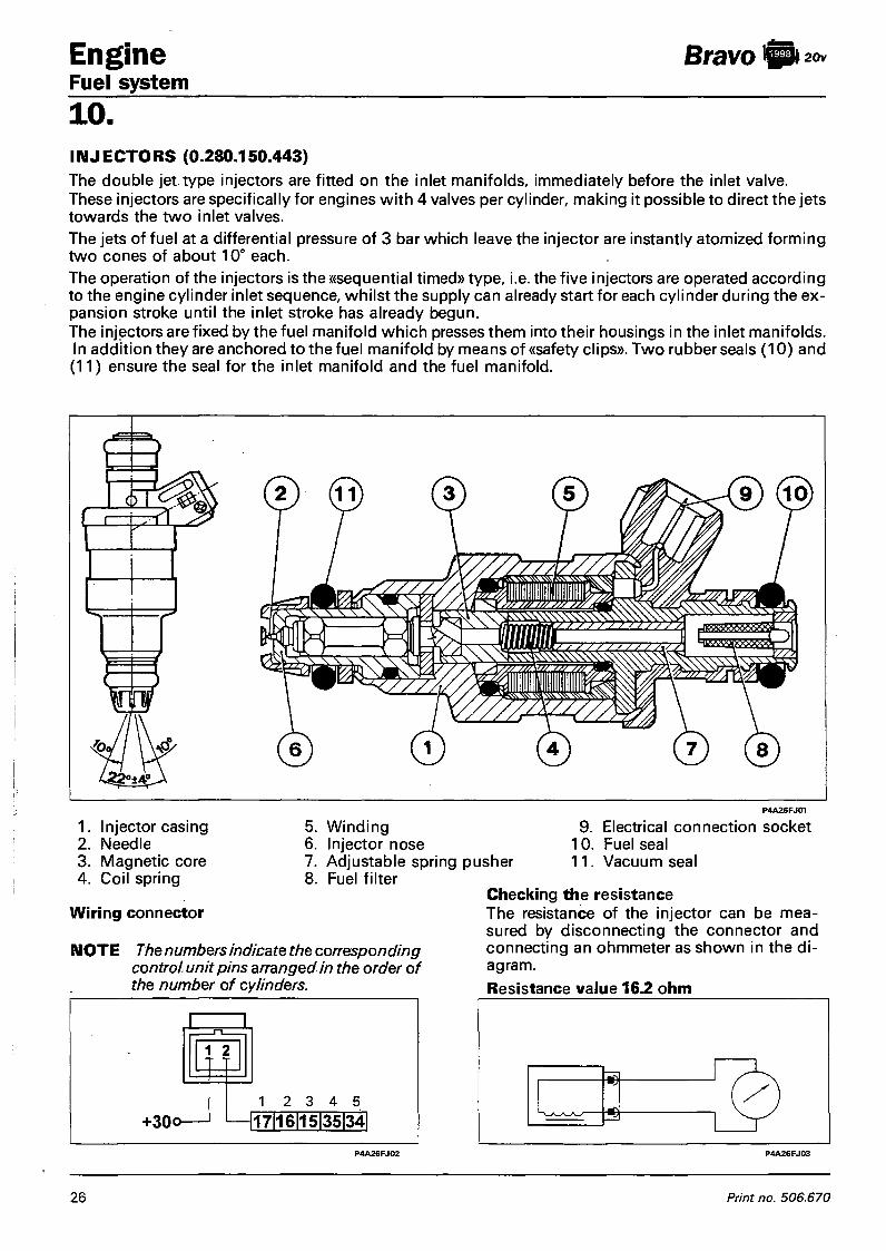
Engine Fuel system 10 .
Bravo ft 20v
I N J E C T O R S (0.280.150.443) The double jet type injectors are fitted on the inlet manifolds, immediately before the inlet valve. These injectors are specifically for engines with 4 valves per cylinder, making it possible to direct the jets towards the two inlet valves. The jets of fuel at a differential pressure of 3 bar which leave the injector are instantly atomized forming two cones of about 10° each. The operation of the injectors is the ((sequential timed» type, i.e. the five injectors are operated according to the engine cylinder inlet sequence, whilst the supply can already start for each cylinder during the expansion stroke until the inlet stroke has already begun. The injectors are fixed by the fuel manifold which presses them into their housings in the inlet manifolds. In addition they are anchored to the fuel manifold by means of «safety clips». Two rubber seals (10) and (11) ensure the seal for the inlet manifold and the fuel manifold.
1. Injector casing 2. Needle 3. Magnetic core 4. Coil spring
Wiring connector
5. Winding 9. 6. Injector nose 10. 7. Adjustable spring pusher 11. 8. Fuel filter
P4A26FJ01
Electrical connection socket Fuel seal Vacuum seal
NOTE The numbers indicate the corresponding control unit pins arranged in the order of the number of cylinders.
Checking the resistance The resistance of the injector can be measured by disconnecting the connector and connecting an ohmmeter as shown in the diagram. Resistance value 16.2 ohm
26 Print no. 506.670
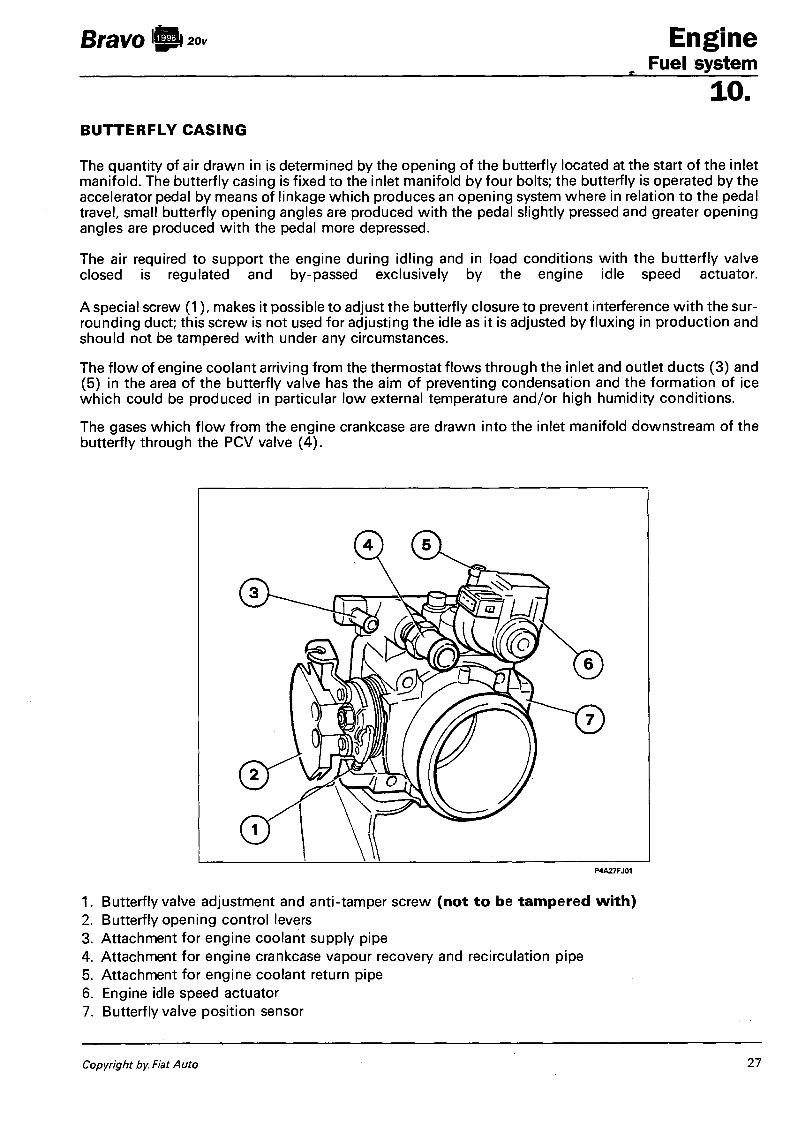
Bravo Engine Fuel system
10. B U T T E R F L Y C A S I N G
The quantity of air drawn in is determined by the opening of the butterfly located at the start of the inlet manifold. The butterfly casing is fixed to the inlet manifold by four bolts; the butterfly is operated by the accelerator pedal by means of linkage which produces an opening system where in relation to the pedal travel, small butterfly opening angles are produced with the pedal slightly pressed and greater opening angles are produced with the pedal more depressed.
The air required to support the engine during idling and in load conditions with the butterfly valve closed is regulated and by-passed exclusively by the engine idle speed actuator.
A special screw (1), makes it possible to adjust the butterfly closure to prevent interference with the surrounding duct; this screw is not used for adjusting the idle as it is adjusted by fluxing in production and should not be tampered with under any circumstances.
The flow of engine coolant arriving from the thermostat flows through the inlet and outlet ducts (3) and (5) in the area of the butterfly valve has the aim of preventing condensation and the formation of ice which could be produced in particular low external temperature and/or high humidity conditions.
The gases which flow from the engine crankcase are drawn into the inlet manifold downstream of the butterfly through the PCV valve (4).
P4A27FJ01
1. Butterfly valve adjustment and anti-tamper screw (not to be tampered with) 2. Butterfly opening control levers 3. Attachment for engine coolant supply pipe 4. Attachment for engine crankcase vapour recovery and recirculation pipe 5. Attachment for engine coolant return pipe 6. Engine idle speed actuator 7. Butterfly valve position sensor
Copyright by Fiat Auto 27

Engine Fuel system 10.
Bravo ft 20v
B U T T E R F L Y VALVE POSITION S E N SOR (0.280.122.001) The sensor is made up of a potentiometer inserted in a plastic container which has two fins, in which there are two openings WITHOUT SLOTS which have the function of ensuring the anchorage and the positionining of the sensor in relation to the butterfly valve. A three pin socket in the container guarantees the electrical connection with the electronic control unit. During operation, the injection/ignition control unit provides the potentiometer with a supply of 5 Volts at pins (1) and (2). There is a voltage at pin 3 which is inversely proportional to the opening position of the butterfly valve. According to the voltage sent by pin 3 the control unit recognizes the opening condition for the butterfly valve and suitably corrects the mixture strength. With the butterfly closed an elecrical voltage signal of around 0.5 Volts reaches the control unit which recognizes the idle and cut off conditions (distinguishing them on the basis of the engine speed). The potentiometer automatically recognizes the butterfly idle position by means of a "self-
Recovery -adjustment" function. This eliminates the , , ., . , ,. , adjustment operations and makes it possible
If the sensor fails, the control unit establishes t 0 a | , o w f o r a n y w e a r w h i c h m a y o c c u r f o r
the following parameters: t h e b u t t e r f | y d o s u r e position.
Butterfly opening angle = 10° idle state: air flow rate < 12.8 m3/h;
exit from idle state: air flow rate > 8 m3/h;
full load state: engine load > 6,5 ms and simultaneous speed > 2000 RPM; exit from full load state: engine load < 6,5 ms or speed < 2000 RPM.
Additional provisions The engine idle speed gradual decrease (dashpot) and idle self-adjustment strategies are stopped.
Wiring connector
P 4 A 2 8 F J 0 2
NOTE The numbers indicate the corresponding control unit pins
28 Print no. 506.670

Bravo b 20v Engine Fuel system
10. ENGINE IDLE (0.280.140.553)
S P E E D ACTUATOR
It is composed of an electric motor which, by opening the flow of supplementary air (in parallel to the flow from the butterfly with the accelerator released) in the butterfly casing more or less, automatically keeps the engine idle speed constant, irrespective of the load conditions (additional consumers switched on or not, engine hot or cold, etc.). The opening caused by the rotation of the distributor is controlled by electrical' impulses processed by a special section in the injection control unit which causes the distributor to rotate in one direction or the other depending on the speed at which the engine is rotating.
Recovery If the actuator fails, the control unit activates different recovery strategies depending on the butterfly valve opening angle.
Recovery 1: valve in recovery position, near the idle air flow rate for: - short circuit battery V at opening or closing winding or opening and closing winding; - open circuit at opening or closing winding or at opening and closing winding - short circuit battery V at opening winding and open circuit at opening winding - short circuit battery V at closing winding and open circuit at opening winding. Recovery 2: valve open 0% for: - short circuit battery V at opening winding and short circuit to earth at closing winding; - open circuit at opening winding and short circuit to earth at closing winding. Recovery 3: valve open 50% for: - short circuit to earth at opening winding or closing winding or opening and closing Recovery 4: valve open 100% for: - short circuit battery V at closing winding and short circuit to earth at opening winding; - open circuit at closing widing and short circuit to earth at opening winding.
Additional provisions Locking the idle self-adjustment at the current values and locking the idle control.
Wiring connector
NOTE The numbers indicate the corresponding control unit pins.
Copyright by Fiat Auto 2 9
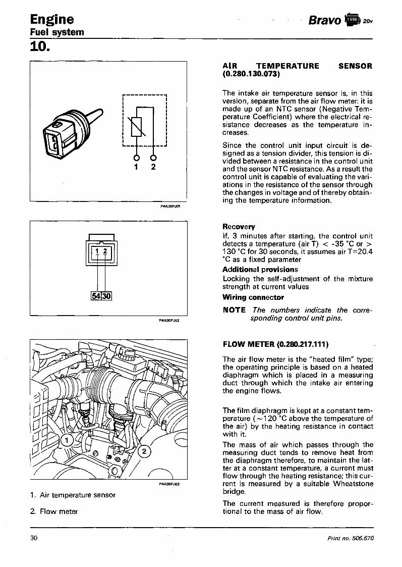
Engine Fuel system 10.
Bravo I) 20v
AIR T E M P E R A T U R E (0.280.130.073)
S E N S O R
The intake air temperature sensor is, in this version, separate from the air flow meter: it is made up of an NTC sensor (Negative Temperature Coefficient) where the electrical resistance decreases as the temperature increases.
Since the control unit input circuit is designed as a tension divider, this tension is divided between a resistance in the control unit and the sensor NTC resistance. As a result the control unit is capable of evaluating the variations in the resistance of the sensor through the changes in voltage and of thereby obtaining the temperature information.
Recovery If, 3 minutes after starting, the control unit detects a temperature (air T) < -35 °C or > 130 °C for 30 seconds, it assumes air T=20.4 °C as a fixed parameter Additional provisions Locking the self-adjustment of the mixture strength at current values Wiring connector
N O T E The numbers indicate the corresponding control unit pins.
P4A30FJ03
1. Air temperature sensor 2. Flow meter
FLOW METER (0.280.217.111)
The air flow meter is the "heated film" type; the operating principle is based on a heated diaphragm which is placed in a measuring duct through which the intake air entering the engine flows.
The film diaphragm is kept at a constant temperature (~ 120 °C above the temperature of the air) by the heating resistance in contact with it. The mass of air which passes through the measuring duct tends to remove heat from the diaphragm therefore, to maintain the latter at a constant temperature, a current must flow through the heating resistance; this current is measured by a suitable Wheatstone bridge.
The current measured is therefore proportional to the mass of air flow.
30 Print no. 506.670

Bravo ft 20v Engine Fuel system
10.
1. Connector
2. Measuring duct
3. Hot film sensor
A= Air intake
IM OTE This flow meter directly measures the mass of air (and not the volume as on previous versions) thereby dispensing with the problems of temperature, altitude, pressure, etc.
Description of the operation The Wheatstone bridge (made up of R3, R2, Rs, Rt+R1) is balanced when the Rs is at about 120 °C above the temperature of the air. The air which passes through the diaphragm removes heat from the Rs, therefore the bridge is unbalanced. This situation is detected by the circuit at IC1 which controls the transistor T1 in a manner which is proportional to the bridge imbalance and as a result more current is passed through Rh to heat Rs and therefore restore the balance for the bridge. The circuit IC2 measures the current which passes through Rh. This current makes it possible to keep the bridge balanced and therefore proportional to the mass of air which passes through the air flow meter.
Recovery In the absence of a simultaneous error at the butterfly potentiometer, the idle engine load is calculated according to the speed if the engine is idling, otherwise a fixedengine load is allocated. If there is a simultaneous error at the butterfly potentiometer, the engine load and advance values are allocated according to a table depending on the number of revs.
IC2
Uk(=)
R 3 Q
C 4 RS -Hf
R2
R T
I C 1
Usub IRS T
- o - t r c r 1 2 3 4
Additional provisions
Locking the self-adjustment of the mixture strength and idle at current values.
Wiring connector
NOTE The numbers indicate the corresponding control unit pins.
Copyright by Fiat Auto 31

Engine Fuel system 10.
Bravo ft 20v
The graph below shows the sensor characteristics which can be measured by disconnecting the connector and connecting an ohmmeter as shown in the diagram at the side.
COOLANT TEMPERATURE SENSOR (0.280.130.026)
The sensor is fitted near the thermostat casing with the sensitive part in contact with the coolant. It is made up of a brass casing which protects the actual resistive element comprising an NTC (Negative Temperature Coefficient) «thermistor», where the electrical resistance of the sensor decreases as the temperature increases). It provides the control unit with a voltage which varies according to the temperature of the engine in order to correct the information concerning the air flow rate from the flow meter so that according to the signal received by the sensor the control unit can control the injection of the fuel for a greater length of time, providing the necessary enrichment when the engine is operating at temperatures below operating temperature.
5 0 0 0 4 0 0 0 3 0 0 0
2 0 0 0
1 0 0 0
5 0 0 4 0 0
300¬
2 0 0 -
- 4 0 - 3 0 - 2 0 - 1 0 0 6 0 8 0 100 120 »c
Recovery If air T < 19.9 °C, it is assumed that engine T = air T for three minutes, then it is assumed that engine T = 80 °C. If air T ^ 19.9 °C, it is assumed that engine T = 80 °C immediately.
Additional provisions Locking the self-adjustment of the mixture strength and idling at current values. Wiring connector The numbers indicate the corresponding control unit pins
32 Print no. 506.670

Bravo I) 20v Engine Fuel system
10. S P E E D O M E T E R SENSOR
The speedometer sensor (vehicle speed sensor) it is composed of a Hall effect sensor and is located at the differential outlet. The sensor transmits a signal to the control unit where the frequency varies according to the speed of the vehicle. The control unit uses this information to improve the management of the engine idle adjustment actuator and for the C U T - O F F strategy.
The speedometer sensor signal is also processed to calculate and memorize the mileage travelled in the control unit; this information can be read using the Fiat I Lancia Tester.
PHASE TRANSFORMER
In order to achieve a good compromise between the high performance in terms of power at high speeds and good torque at low speeds, a phase transformer (electronically and hydraulically operated) is fitted for the inlet camshaft. This device makes it possible to alter the timing diagram (inlet phase) according to the engine load conditions; this parameter is processed by the MOTRONIC control unit on the basis of the electrical signals received by the air flow meter and the rpm sensor and sent to the phase transformer solenoid valve. The construction of the device involves a main assembly fitted on the inlet camshaft which has the task of altering the angular position of the actual shaft in relation to the drive pulley. In addition there is a valve, operated by an electro-magnet, both of which are on the inlet manifold and connected hydraulically to the main assembly by appropriate ducts. The operating principle is as follows: - with the temperature of the coolant below 40 °C and when the engine is idling or the speed exceeds
4800 rpm, the electro-magnet (1) is de-energized, therefore the valve (2) thrust by the opposing spring (3) remains raised not allowing the oil which is arriving from the duct (A) to reach the transformer. In this case the timing of the inlet valves remains unaltered. With the temperature of the coolant above 40 "C and with the engine speed above idle and below 4800 rpm with the butterfly angle greater than about 8°, the electro-magnet (1) is energized, thereby thrusting the valve (2) downwards. In this position the oil, coming from the duct (A), enters the piston chamber (B) and from here flows via a special opening into the duct (C) inside the latter. The oil can only leave the above mentioned duct via the upper port (in contact with duct (D) supplying oil to the transformer) because with the valve (2) lowered, the lower port is not in contact with the discharge duct (E). The oil reaches the chamber (G) through ducts (D) and (F) moving the piston (4) axially towards the engine; because this piston has helical teeth on the outside this axial movement causes it to rotate in a clockwise direction (as seen from the timing side). This rotation is transmitted, by means of a straight toothed splied profile, to the pinion (5) which, bolted onto the threaded end of the camshaft (6), transmits the rotation to the shaft, thereby varying the timing of the inlet valves by an advance of 9°.
When the electro-magnet is de-energized, the valve (2) returns to the original position, interrupting the flow of oil under pressure to the chamber (G), but allowing the return of the oil to the exhaust, thanks to the force of the opposing spring (7).
Copyright by Fiat Auto 33

Engine Fuel system 10 .
Bravo l j 20v
An additional duct ensures the lubrication of the bearing on the camshaft even when the device is not activated. The oil which reaches the chamber (H) for the electro-magnet is discharged through the drainaqe duct (E).
Recovery
If the solenoid valve fails, the final stage (driver) in the control unit is deactivated.
1. Solenoid valve 2. Valve 3. Valve spring 4. Piston 5. Pinion 6. Camshaft end section 7. Piston spring
8. Battery 9. Injection/ignition system relay
10. Phase transformer solenoid valve relay feed 11. Injection/ignition control unit 12. Ignition switch
34 Print no. 506.670

Bravo 0 * * Engine Fuel system
10. LAMBDA SENSOR (0.258.003.466)
To meet the strict legislation governing the emission of harmful residues from internal combustion engines which require increasingly more precise metering of the air/fuel mixture, the vehicle has been equipped with a heated Lambda sensor with four wires which measures the oxygen content of the exhaust gases. For a complete description of the Lambda sensor, refer to the Fuel System section for the 1581 16V engine.
The sensor can be rapidly put out of action by even the slightest amounts of lead in the fuel.
Removing - ref itti ng - Position the vehicle on a lift.
- Disconnect the negative lead from the battery.
- Disconnect the electrical connection under the butterfly casing.
- Raise the vehicle. - Remove the Lambda sensor from its hous
ing.
- When tightening, do not exert force on the component or it will be irreparably dam-aofid.
If the Lambda sensor is being replaced, when refitting smear anti--seize grease on the threaded part (e.g. Bosch VS 14016- FT).
Tightening torque 5 - 6 daNm
Recovery The Lambda data is ignored (open loop) if the sensor voltage is> 1,099 V or between 0.400 and 0.518 V for more than 2.55 s. Locking of self-adjustment of mixture strength for sensor voltage < 0,0879 V for more than 2.55 s. Open loop is considered the maximum Lambda integrator value (FR) for the last good sensor voltage reading < 0.0879 V and simultaneously FR=1.4. Locking of FR at limit value reached for FR > 1.25 or < 0.75 for at least 15 s. Wiring connector The numbers indicate the corresponding control unit pins.
Copyright by Fiat Auto 35

Engine Fuel system
Bravo
10. Checking the resistance The resistance of the sensor heater can be measured by disconnecting the connector and connecting an ohmmeter as shown in the diagram. Resistance: 4.5 ± 0.5 ohm at 20 °C CHARCOAL FILTER AND FUEL VAPOUR CUT OUT SOLENOID VALVE The charcoal filter and the solenoid valve are located in the right wheel arch. For the description of the charcoal filter refer to the Fuel System section for the 1581 16V engine.
1. Vapour cut out solenoid valve 2. Charcoal filter
Vapour cut out solenoid) valve (0.280.142.300) The function of this valve is to control the quantity of petrol vapours drawn in by the active charcoal filter and directed to the inlet manifold by means of the electronic control unit. If this valve is not supplied it is in the open position; if the key is turned to the ON position, it closes preparing for operation. In effect, if energized the solenoid valve (6) attracts the shutter (4) which, overcoming the spring (3) loading, closes the port (5) preventing the flow of petrol vapours. The operation is controlled by the electronic control unit as follows: - during starting the solenoid valve remains
closed, preventing the petrol vapours from excessively enriching the mixture;
- when the engine has been started up, the electronic control unit sends a signal to the solenoid valve which modulates the opening.
In this way the control unit controls the quantity of petrol vapours sent to the inlet, thereby preventing considerable variations (above all during idling) in the mixture strength.
NOTE The solenoid valve must be fitted correctly: the arrow on its casing should be facing the vacuum inlet on the inlet manifold.
1. Inlet union 2. One-way valve 3. Spring 4. Shutter 5. Outlet port 6. Solenoid valve 7. Outlet union
36 Print no. 506.670

Bravo $20v Engine Fuel system
10. Removing-refitting
The procedure is valid for both the charcoal filter and the vapour cut out solenoid valve. .
- Raise the vehicle;
- remove the right front wheel;
- remove the rear liner for the right front wheel arch;
- undo the bolt which fixes the component concerned to the mounting bracket;
- remove the electrical connection and the pipes connected;
- remove the component concerned.
Recovery Locking self-adjustment of mixture strength. Locking the self-adjustment of the fuel anti-evaporation system.
Wiring connector
NOTE The numbers indicate the corresponding control unit pins.
INERTIA SWITCH In order to increase the degree of safety for the occupants of the vehicle in the case of an impact, the vehicle is equipped with an inte-ria switch located inside the passenger compartment, under the driver's seat. This sensor reduces the possibility of fire (as a result of fuel escaping from the injection system) by de-activating the electric pump which supplies the injection circuit. For the complete description and the removing-refitting procedure, refer to the Fuel System section for the 1581 16V engine.
A After even a slight impact, if there is a smell of fuel or there are leaks from the fuel system, do not turn the switch back on, but search for the problem and correct it to prevent the risk of fire.
Copyright by Fiat Auto 3 7

Engine Bravo | 20v
Fuel system 10. MULTI-PURPOSE VALVE AND SAFETY AND VENTILATION VALVE
These valves belong to the fuel vapour anti-evaporation and recirculation system. For their description refer to the Fuel System section for the 1581 16V engine.
C H E C K S / A D J U S T M E N T S AND REPAIR OPERATIONS TO BOSCH MOTRONIC M 2.10.4 INJECTION/ IGNITION S Y S T E M APART FROM FAULT DIAGNOSIS WITH THE F I AT/LANCIA T E S T E R
A WHEN WORKING ON A VEHICLE EQUIPPED WITH A MOTRONIC INJECTION/IGNITION SYSTEM THE FOLLOWING PRECAUTIONS MUST BE OBSERVED:
- do not start up the engine with the electrical connection terminals not properly connected or slack at the battery poles;
- never use a rap'id battery charger to start the engine;
- never disconnect the battery with the engine running;
- to rapidly charge the battery it must be disconnected first from the vehicle's electrical system; - if the vehicle is going in a drying oven after painting where the temperatures are in excess of
80 °C, it is necessary to remove the injection/ignition electronic control unit;
- never attach or disconnect the electronic control unit multiple connector with the ignition switch in the ON position;
- always disconnect the negative battery lead before carrying out electrical welding on the vehicle.
Remember that this system has a memory which is always supplied (stand-by memory) wherethe self-adjustment values are memorized. The operation of disconnecting the battery results in this information being lost but it can be acquired again after a certain mileage; this operation should therefore be restricted.
EE A D J U S T M E N T OF A C C E L E R A T O R CONTROL CABLE
The adjustment of the accelerator cable is obtained by moving the clip (4) in the different bush (3) splines.
Position the clip in such a way that the head (1) of the accelerator cable freely enters the slot (2) without altering the engine idle speed.
38 Print no. 506.670

Bravo ft Engine Fuel system
10. REMOVING-REFITTING F U E L MANIFOLD C O M P L E T E WITH I N J E C T O R S AND P R E S SURE REGULATOR
Proceed as follows: - Disconnect the fuel supply pipe (5) from the
union. - Loosen the band for the return pipe and dis
connect the flexible rubber pipe from the rigid pipe.
- Disconnect the electrical connectors from the injectors.
- Undo the fixing bolts (7). - Extract the injector manifold assembly.. - To remove the injectors from the fuel mani
fold, remove the clip (9).
1. Fuel manifold P 4 A 3 9 F J O 2
2. Fuel pressure regulator 3. Injectors 4. Vacuum pick up from engine inlet manifold 5. Fuel supply pipe from the electric pump 6. Fuel return pipe to the tank 7. Bolts fixing fuel manifold and injectors 8. Pressure regulator clip on fuel manifold 9. Injector clip on fuel manifold
Copyright by Fiat Auto 3 9

Engine Fuel system 10.
Bravo b 20v
C H E C K S ON F U E L SUPPLY C I R C U I T
1st Test
Checking fuel regulation pressure
- Disconnect the fuel supply pipe to the manifold from the union shown by the arrow;
- Place pressure gauge 189589000 with both taps A and B in the open position between the end of the pipe disconnected and the fuel manifold;
IFI HAITI
- operate the electric fuel pump with the engine switched off with the help of the Fiat/Lancia Tester activating the "fuel pump" test;
- the pressure reading on the pressure gauge should stabilize in these test conditions at around 3 bar. If the pressure is insufficient, carry out the 2nd test.
2nd Test
Checking maximum fuel supply pressure (or electric pump efficiency)
The same connections as for the previous test apply. - Close lever A for the fuel tap (downstream
of the pressure gauge); - operate the electric pump with the engine
switched off, as described in the previous test: the pressure should reach 6 bar and not exceed 7.5 bar (pump safety valve calibration). If this is not the case, replace the electric pump because it is defective.
40 Print no. 506.670
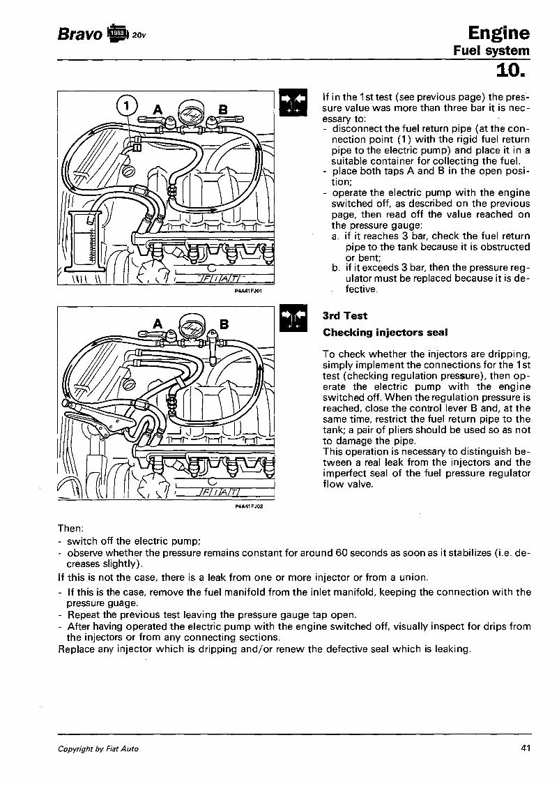
Bravo S i Engine Fuel system
y — i o J— 1 i r - r r IT—rf ~ ^ r - f T —
1 0 .
iFlllAlTl
If in the 1 st test (see previous page) the pressure value was more than three bar it is necessary to: - disconnect the fuel return pipe (at the con
nection point (1) with the rigid fuel return pipe to the electric pump) and place it in a suitable container for collecting the fuel.
- place both taps A and B in the open position;
- operate the electric pump with the engine switched off, as described on the previous page, then read off the value reached on the pressure gauge: a. if it reaches 3 bar, check the fuel return
pipe to the tank because it is obstructed or bent;
b. if it exceeds 3 bar, then the pressure regulator must be replaced because it is defective.
3rd Test Checking injectors seal
To check whether the injectors are dripping, simply implement the connections for the 1 st test (checking regulation pressure), then operate the electric pump with the engine switched off. When the regulation pressure is reached, close the control lever B and, at the same time, restrict the fuel return pipe to the tank; a pair of pliers should be used so as not to damage the pipe. This operation is necessary to distinguish between a real leak from the injectors and the imperfect seal of the fuel pressure regulator flow valve.
Then: - switch off the electric pump; - observe whether the pressure remains constant for around 60 seconds as soon as it stabilizes (i.e. de
creases slightly). If this is not the case, there is a leak from one or more injector or from a union. - If this is the case, remove the fuel manifold from the inlet manifold, keeping the connection with the
pressure guage. - Repeat the previous test leaving the pressure gauge tap open. - After having operated the electric pump with the engine switched off, visually inspect for drips from
the injectors or from any connecting sections. Replace any injector which is dripping and/or renew the defective seal which is leaking.
Copyright by Fiat Auto 41

Bravo fti 20v Engine Fuel system 10. CHEKCING ENGINE IDLE S P E E D
If the engine idle speed is not 750 ± 50 rpm and the injection/ignition control unit is the self-adjusting type, it is not possible to adjust it, therefore it is necessary to check that the accelerator linkage is correctly adjusted and to then search for the cause of the problem by carrying outa complete fault diagnosis using the Fiat/Lancia Tester.
CHECKING CONCENTRATION OF POLLUTANT EMISSIONS
The Motronic M 2.10.4 system ensures a constant check on the idle speed and the CO percentage through the self-adjustment of the system, thereby making any outside adjustments superfluous (there are no adjustment screws). However, a check on the content of the exhaust gases downstream of the catalyzer can provide precious indications on the operation of the injection/ignition system, the engine parameters and the catalyzer.
Checking idle concentration of CO and HC The concentration of carbon monoxide (CO) and unburnt hydrocarbons (HC) is measured with the catalyzer at operating temperature (300 - 350 °C) (it is advisable to drive "hard" for around 5 - 1 0 minutes to make sure that the catalyzer reaches operating temperature), then insert the suitably tester probe at least 30 cm into the end of the exhaust pipe as shown in the diagram.
If the shape of the end section of the exhaust pipe is such that the sensor cannot be completely introduced, a special extension pipe must be added which ensures the seal in the join area.
1. Check that the CO and HC concentrations are within the values given in the table; 2. If the CO value is not within the recommended figures, it is necessary to check:
- the correct operation of the Lambda sensor, using the Fiat/Lancia Tester; - the presence of air penetration in the area surrounding the Lambda sensor housing; - the injection and ignition system (in particular the state of wear of the spark plugs).
3. If the HC value is outside of the recommended limits, the cause of the problem should be sought in the incorrect engine timing or the decreased efficiency of the catalyzer.
CO (%) HC (p.p.m.) C02 (%)
< 0,35 ^ 90 > 13
Table summarizing pollutant emission tolerances downstream of the catalyzer
42 Print no. 506.670

Bravo ft20v Engine Fuel system
10. DIAGNOSIS
The complete diagnosis of the system is possible through active dialogue with the Fiat/Lancia Tester.
If a failure is detected for the sensors the electronic control unit replaces the information coming from the faulty sensor with information memorized (recovery) so that the engine can still operate. The detection of the problem involves it being memorized permanently and the exclusion of the sensor from the system until the signal is compatible once again. The same procedure is applied if the problem involves an actuator or its control holder. The detection of the problem and the replacement with recovery data involves signalling the problem by the special warning light in the instrument panel coming on.
The parameters which can, in the case of a breakdown, be managed by the control unit are: flow meter, idle adjustment actuator, coolant temperature sensor, butterfly valve position sensor, Lambda sensor, air temperature sensor, battery voltage and detonation sensors. If there are problems with the control unit, the timing sensor or the injectors, the system does not detect the problem and the vehicle breaks down. The problems can be read by an operator on the control unit using the Fiat/Lancia Tester.
Detecting problems This is carried out during the basic function which manages the sensor/actuator.
Memorizing the error and the structure of the errors memory The errors are memorized in the control unit in the order in which they occur in the RAMS. For each of them the location and type of error, 2 environmental conditions (specific to each type of problem) measured the moment in which the problem is detected and a frequency counter is memorized.
Classification of the defect If a defect is recognized for the first time and the error state persists for a time t > 0.5s, the defect is memorized as "permanent". If this defect then disappear, it is memorized as "intermittent" and "not present". If it then reappears, it remains memorized as "intermittent", but becomes "present".
The classification of a problem as "permanent" activates the recovery functions; when the problem disappears the normal function of reading or implementation is restored. Certain types of problem are classified as "important", i.e. in terms of anti-pollution regulations. The presence of these problems is signalled to the user by means of the failure warning light in the instrument panel coming on.
Frequency counter For each error there is a frequency counter, which is used to determine the moment in which a problem which is no longer present has been memorized. The first time the problem is detected, the counter is set at 10. If the fault disappears, the counter remains at the current value. If it reappears, it is increased by 1 (to an upper limit of 50).
The counter is decreased each time the engine is started up without the fault reappearing. If the counter reaches zero then the fault is automatically cancelled from the memory. If after having decreased the counter the fault should reapper, the counter returns to a value of 10 (if, however, it is greater than 10, it is not altered).
Signalling failures
The failure warning light comes on when there is a defect memorized as "present" and "important". The delay time between detecting the problem and the warning light coming on is 0.1 seconds; the delay time between the disappearance of the problem in the memory and the warning light going out is 4 seconds. The warning light comes on each time the ignition key is turned to the ON position. If there are "important" problems already present, the warning light goes out after 4 seconds.
Copyright by Fiat Auto 43

Engine Bravo ft** Fuel system
10. Cancelling the error
When the frequency counter reaches the value 0, the error is cancelled and so are the parameters associated with it.
The immediate cancelling of the entire errors memory takes place in the following cases:
- by means of the "cancel errors memory" command sent by the tester;
- by interrupting the supply to the injectors control unit (disconnecting the battery or the connector for the control unit).
Fault diagnosis with the Fiat/Lancia Tester
On the right hand side of the engine compartment (near the engine oil dip stick) is the diagnostic socket to which the Fiat/Lancia Tester is connected.
The exchange of data between the control unit and the Tester takes place via a two direction serial line (line K) using the standard Bosch communication protocol.
The Tester can supply the following information:
- display of the errors;
- display of engine parameters;
- active diagnosis.
List of errors
Rpm sensor Butterfly potentiometer Air temperature sensor Coolant temperature sensor Battery
Lambda sensor Injector Idle speed actuator Petrol vapour solenoid valve Actuator relays Control unit
Flow meter Timing sensor Detonation sensor Speedometer sensor Phase transformer Electric fuel pump Fiat CODE
Loss of signal C C . C C . C A - C C . Supply> 16,01V. Supply < 10V. C A - C C - Incorrect CO value C C C C C C C C Operating problems for the micro-processor or control unit memories are signalled.
C C Signal missing or not plausible Signal missing or not plausible Signal missing or not plausible C C C C Code not recognized or not received
44 Print no. 506.670

Bravo fti20v Engine Fuel system
10. Parameters displayed
Engine rpm Injection time Advance Intake air temperature Coolant temperature Butterfly valve opening angle Battery voltage Lambda sensor Self-adjustment Flow meter Engine knocking (detonation) Vehicle speed Petrol vapour cut out solenoid valve Fiat CODE Mileage travelled
Active diagnosis The following active tests can be carried out using the Fiat/Lancia Tester: - Phase transformer - Injector - Failure warning light - Petrol vapour solenoid valve - Air conditioning - Idle speed actuator - Cancelling errors.
If there are problems with the sensors, the control unit replaces the value transmitted by the sensor with a so called Recovery value which, depending on the different problems, is stored in the control unit memory or is specially reconstructed from the other information available, in order to allow the vehicle to reach a service centre. This value is also transmitted to the Fiat/Lancia Tester, therefore, during the fault diagnosis it is worth bearing in mind that in the case of problems the Fiat/Lancia Tester will signal the error for the sensor concerned and the Recovery value will be displayed. Permanent memory The control unit is equipped with a «permanent»type errors memory (EEPROM), i.e. the error indication is preserved even if the cause of the problem no longer exists and the key has been turned to the OFF position; it also has a «volatile» type memory (RAM) which, on the other hand, loses the error information as soon as the cause disappears. This also allows the more effective detection of errors of an occasional nature. Before ending the fault diagnosis the contents of the «permanent» memory should be cancelled using the Fiat/Lancia Tester in Active Diagnosis. The contents of the «permanent» errors memory can be cancelled in the following ways: 1 - Using the Fiat/Lancia Tester in active diagnosis. If this is not the case, when the Fiat/Lancia Tester is reconnected the errors already examined are signalled. 2 - If the cause of the error is no longer present and the engine has been started up 5 times (working for ^ ^ ^ e a s t 20 minutes) with a gap of at least 2 minutes between one starting and the next.
Disconnecting the control unit from the system, even for long periods of time, does not cancel the contents of the ((permanent)} memory.
Recovery
Copyright by Fiat Auto 45


Bravo-Brava Engine Contents
1 0 .
FUEL SYSTEM page
Removing-refitting injection pump on vehicle 1 - Removing injection pump 1 - Refitting injection pump 4 - LUCAS FT05 injection pump . 5 Adjusting pump timing on engine 6 - Fitting pump and checking advance
on engine 6 - Fitting injection pump 6 - Final check 7 Possible adjustments on injection pump fitted to engine 7 - Anti-stall speed adjustment 7 - Checking antistall screw setting 8 - • Adjusting engine top speed 8 Bleeding pump hydraulic circuit 9 - Bleeding air from diesel fuel 10 - Replacing cartridge fuel filter 10 Fault diagnosis 11 - Introduction 11 - Test tables ]2 Checking exhaust smoke using opaci meter 16 Fuel system diagram " 18 Air intake circuit diagram 19
Copyright Fiat Auto

Bravo-Brava ft ° Eng ine Fuel system
10.
REMOVING-REFITTING INJECTION PUMP ON VEHICLE
Removing injection pump
1. Unscrew the bolts indicated and remove air intake assembly with connection sleeve to air cleaner container.
2. Remove the following parts from the pump:
1. Fast idle cable. 2. Accelerator cable. 3. Electrical connection for engine stop
solenoid (electrostop). 4. Fuel delivery line. 5. Fuel return line to tank. 6. Fuel return line from injectors.
3. Disconnect fuel delivery lines from injectors using tool 1852138000.
4. Disconnect fuel delivery lines from injection pump to injectors.
P4A01DJ04
Copyright Fiat Auto 1

Engine Fuel system
Bravo-Brava !SP>
10.
P4A02DJ03 P4A02DJ02
1. Remove timing belt by unscrewing the nuts indicated and the two retaining bolts and nuts located on the rear end.
2. Loosen the screw retaining the mobile belt tensioner.
3. Remove the timing belt.
4. Prevent injection pump pulley turning using tool 1860765000 and unscrew the pulley retaining bolt.
5. Use tool 1860886000 to remove the injection pump pulley from the tapered fitting.
P4A02DJ05 P4A02DJ04
P4A02OJ07 P4A02DJ06
2 Publication no. 506.670

Bravo-Brava ft ° Engine Fuel system
10.
1. Unscrew the bolts indicated and disconnect the injection pump retaining bracket from the support beam fastened to the engine block
2. Use tool 1850167000 to unscrew the nuts shown.
3. Unscrew the socket screw retaining the injection pump to the mount.
4. Disconnect the rear retaining bracket and remove the pump from the engine bay.
P4A03DJ03
P4A03DJ04
Copyright Fiat Auto 3

Engine Fuel system
Bravo-Brava fti °
10 .
P4A04DJ05 P4A04DJ03
Refitting injection pump
To refit the injection pump, reverse the order of removal operations and carry out the following checks:
1. Position the injection pump drive pulley so that the reference mark on the gear is aligned with the reference mark on the rear timing belt cover.
2. Check notches on alternator pulley (damping flywheel) and coolant pump are properly aligned.
3. Cheek that the notch on the timing drive gear is aligned with the hole on the rear timing belt cover.
4. Also check that the notch on the gearbox bell housing corresponds with the notch on the flywheel.
5. Fit the timing belt.
Check belt condition every 60000 km and replace if: - it is soaked in oil or coolant; - it shows signs of cracks or broken
teeth; - it is frayed or tooth profiles are worn.
A Replace the toothed belt every 120,000 Km or during service operations involving removal at mileages in excess of 30,000 Km.
P4A04DJ07 P4A04DJ06
Publication no. 506.670

Bravo-Brava Eng ine Fuel system
10. Adjust toothed timing belt tension as follows:
Fit part 1860745200 to tool 1860745100. Then position weight at a distance of 120 mm along the calibrated rod and secure. Apply the resulting tool to the mobile belt tensioner as shown in figure. Adjust joint to move calibrated rod to a horizontal position. Then tighten joint retaining screw. Settle the toothed belt by turning the crankshaft through two turns in the direction of rotation. Tighten mobile belt tensioner retaining screw.
The calibrated rod may move away from the horizontal during the final stage. In this case, adjust joint again to restore calibrated rod to its original position and repeat the operation.
Tighten mobile belt tensioner to the specified final torque.
LUCAS FT05 injection pump 1. Maximum rpm adjustment screw. 2. Anti-stall adjustment screw. 3. Fitting for adjusting pump timing on en
gine. 4. Fast idle adjustment screw. 5. Fast idle control lever. 6. Choke advance valve control rod. 7. Choke advance valve. 8. Engine stop solenoid protective cover. 9. Transfer pressure valve (*).
10. Fittings for diesel delivery lines to injectors.
11. Fitting for diesel return line from injectors.
12. Fitting for diesel return line to tank. 13. Accelerator control lever. 14. Fitting for diesel delivery line from filter. 15. Enrichment flow cut-out or supplement
valve. 16. Automatic advance device. 17. Fiat CODE system interface ECU. (*) This valve performs the following func
tions: a. Creates transfer pressure generated by
vane pump. b. Controls transfer pressure on the basis of
engine rpm c. Allows pump to fill with diesel during
start-up (priming)
P4A05DJ03
Copyright Fiat Auto 5
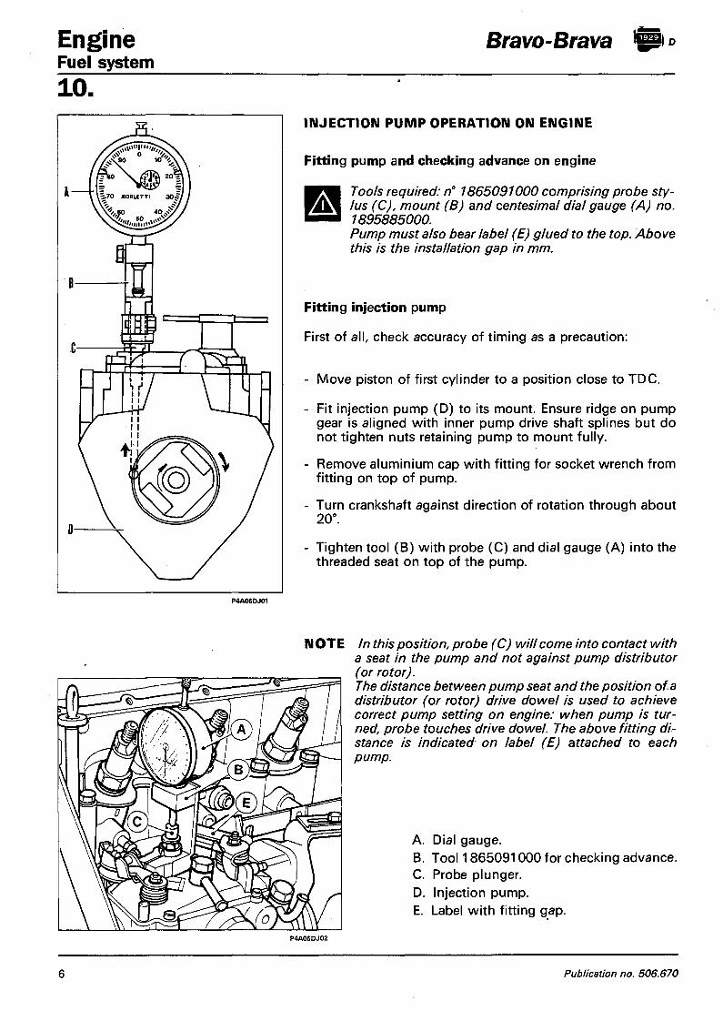
Engine Fuel system
Bravo-Brava ft
10 . INJECTION PUMP OPERATION ON ENGINE
Fitting pump and checking advance on engine
A Tools required: n° 1865091000 comprising probe stylus (C), mount (B) and centesimal dial gauge (A) no. 1895885000. Pump must also bear label (E) glued to the top. Above this is the installation gap in mm.
Fitting injection pump
First of all, check accuracy of timing as a precaution:
- Move piston of first cylinder to a position close to TDC.
- Fit injection pump (D) to its mount. Ensure ridge on pump gear is aligned with inner pump drive shaft splines but do not tighten nuts retaining pump to mount fully.
- Remove aluminium cap with fitting for socket wrench from fitting on top of pump.
- Turn crankshaft against direction of rotation through about 20°.
- Tighten tool (B) with probe (C) and dial gauge (A) into the threaded seat on top of the pump.
N OTE In this position, probe (C) will come into contact with a seat in the pump and not against pump distributor
ce between pump seat and the position of a (or rotor) drive dowel is used to achieve
mp setting on engine: when pump is tur-; touches drive dowel. The above fitting di-indicated on label (E) attached to each
A. Dial gauge. B. Tool 1865091000 for checking advance. C. Probe plunger. D. Injection pump. E. Label with fitting gap.
P4A06DJ02
6 Publication no. 506.670
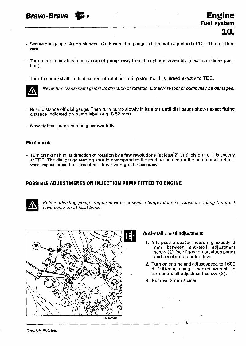
Bravo-Brava fto Eng ine Fuel system
10. - Secure dial gauge (A) on plunger (C) . Ensure that gauge is fitted with a preload of 10 - 1 5 mm, then
zero.
- Turn pump in its slots to move top of pump away from the cylinder assembly (maximum delay position).
- Turn the crankshaft in its direction of rotation until piston no. 1 is turned exactly to TDC.
Never turn crankshaft against its direction of rotation. Otherwise tool or pump may be damaged.
Read distance off dial gauge. Then turn pump slowly in its slots until dial gauge shows exact fitting distance indicated on pump label (e.g. 8.52 mm).
Now tighten pump retaining screws fully.
Final check
- Turn crankshaft in its direction of rotation by a few revolutions (at least 2) until piston no. 1 is exactly at TDC. The dial gauge reading should correspond to the reading printed on the pump label. Otherwise, repeat procedure described above with greater accuracy.
POSSIBLE ADJUSTMENTS ON INJECTION PUMP FITTED TO ENGINE
Before adjusting pump, engine must be at service temperature, i.e. radiator cooling fan must have come on at least twice.
Anti-stall speed adjustment
1. Interpose a spacer measuring exactly 2 mm between anti-stall adjustment screw (2) (see figure on previous page) and accelerator control lever.
2. Turn on engine and adjust speed to 1600 ± 100/min, using a socket wrench to turn anti-stall adjustment screw (2).
3. Remove 2 mm spacer.
Copyright Fiat Auto
1.
1

Engine Bravo-Brava fti * Fuel system 10. 4. Adjust idle speed to 780±50/min by means of idle adjustment screw (4) (see figure on page 7) after
loosening locknut. After adjustment, tighten idle adjustment screw locknut.
5. Move idle control and fuel cut-off lever (18) by hand (see figure on page 7) toward cut-off position by 0.5 -1 mm. The engine should tend to stall or at least speed should drop. If this does not occur, repeat the previous adjustments described at points 1 - 2 - 3 - 4 to obtain a new engine speed that still lies between 780±50 rpm: then repeat test until a positive result is obtained.
Checking antistall screw setting
Accelerate engine to maximum speed, then release accelerator completely: speed should drop steadily to idle level without fluctuations or judder. Otherwise adjust anti-stall screw as follows:
- if deceleration is too slow, unscrew anti-stall adjustment screw (2) by 1/4 turn
- if deceleration is too fast, tighten anti-stall adjustment screw (2) by 1 /4 turn.
Adjusting engine top speed
Move accelerator control lever to end of its travel. If maximum speed of 5150 ± 50 rpm is exceeded, adjust maximum speed screw (1) by tightening until engine speed is as specified. Then tighten nut of screw (1) and apply a lead seal.
1. maximum rpm adjustment screw 2. anti-stall adjustment screw.
P4A08DJ01
8 Publication no. 506.670

Bravo-Brava Engine Fuel system
10. BLEEDING PUMP HYDRAULIC CIRCUIT
If engine stalls due to lack of fuel or if fuel low pressure lines have been disconnected or fuel filter has been changed, proceed as follows to facilitate pump self-priming:
- unscrew fittings fastening delivery lines to injectors (A); - start engine and run until fluid emerges from open injector fittings; - keep engine running and tighten injector fittings.
If engine will not start, check all fuel inlet pipe union points (D) and also fittings (E). Replace seal washers to eliminate the possibility of air leaks.
P4A09DJ01
Diagram showing fuel system connections
Copyright Fiat Auto 9

Engine Bravo-Brava Fuel system 10. Bleeding air f rom diesel (See illustration on previous page) Each time the oil is changed, bleed off the water from the fuel filter as follows:
- unscrew water bleed screw (B) under filter, - unscrew air bleed screw (C) above the filter. Start up engine and let water and fuel emerge until no more water is present, then tighten water bleed screw (B) beneath filter and air bleed screw (C) above filter.
Replacing cartridge fuel filter Change diesel filter every 15,000 km. Proceed as follows to change:
- lubricate rubber cartridge seal, - fill filter cartridge with diesel (in order to reduce self-bleeding period), - tighten cartridge until it touches the mount, - tighten cartridge by 6/8 turn (to obtain torque of 1.3 - 1.6 daNm).
This is achieved using numbered notches engraved on the cartridge. For example when the cartridge is moved into contact with the mount, make a mark on the mount against one of the notches engraved on the filter. Then tighten filter through 6 further notches after the reference notch.
Reference Reference mark / * \ mark
f •»* Cartridge CO -J h-* Cartridge in-]
3
Tightening by hand Tightening to torque (6 notches)
P4A10DJ01
Method for tightening cartridge fuel filter to torque
10 Publication no. 506.670

Bravo-Brava $ ° Engine Fuel system
10. FAULT DIAGNOSIS Introduction
The main differences experienced when working on a Diesel engine, compared to a petrol engine, are as follows:
1) The diesel fuel system is driven by an injection pump and also comprises:
- a tank and two fuel feed and return lines; - a fuel filter (with hand pump for bleeding fuel system); - injectors with high pressure inlet lines; - preheating device for starting engine when cold; - an engine arrest device.
A The injection pump is the most reliable part of the fuel system due to very low component wear and low likelihood of incorrect adjustment. Engine failure should not immediately be attributed to the injection pump but more probably to one of the other fuel system components.
2) The combustion process within a Diesel spontaneous fuel self-ignition engine produces very high temperatures. Coupled with the fact that the fuel inevitably contains traces of sulphur, this determines: - greater tendency than petrol engines to produce sparks and thus greater wear on moving parts,
particularly those close to the combustion chamber; - greater tendency of piston rings to become bonded in their seats.
It is very important to change the fuel filter every 15,000 km. Use only specified lubricant oil grade. Engine oil must be changed every 7500 km. If vehicle is used under heavy conditions (mainly town driving, continuous mountain driving, towing of trailers or caravans, routes through dusty areas) change oil more frequently, particularly when the temperature exceeds 25°C. • Make sure injectors are always efficient in order not to increase productiorrvf uncombusted products during engine operation.
3) The combustion process in spontaneous self-ignition diesel engines also gives rise to higher engine noise levels (*) with the production of combustion knock clearly discernible from outside. Although this phenomenon has been greatly reduced in present-day engines with prechambers, it is still present, particularly at low speed, but tends to diminish at medium-high speeds.
NOTE If the injection pump is advanced only slightly in relation to correct timing setting, combustion knock is considerably accentuated.
4) An indirect injection Diesel engine needs a prechamber preheating device (rapid glow plugs and ECU) to facilitate fuel self-ignition when the engine is cold and hence engine start-up. A special solenoid is used to turn off the engine (which occurs when the fuel supply to the injection pump ceases). This opens up fuel flow in the injection pump when the ignition key is in MARCIA position and turns it off when the ignition key is turned to STOP.
(*) Engine running noise: this is due t o an excessive fuel pressure gradient, i.e. the ratio between pressure deve loped by combust ion and corresponding crankshaft angles of rotat ion.
Copyright Fiat Auto 11
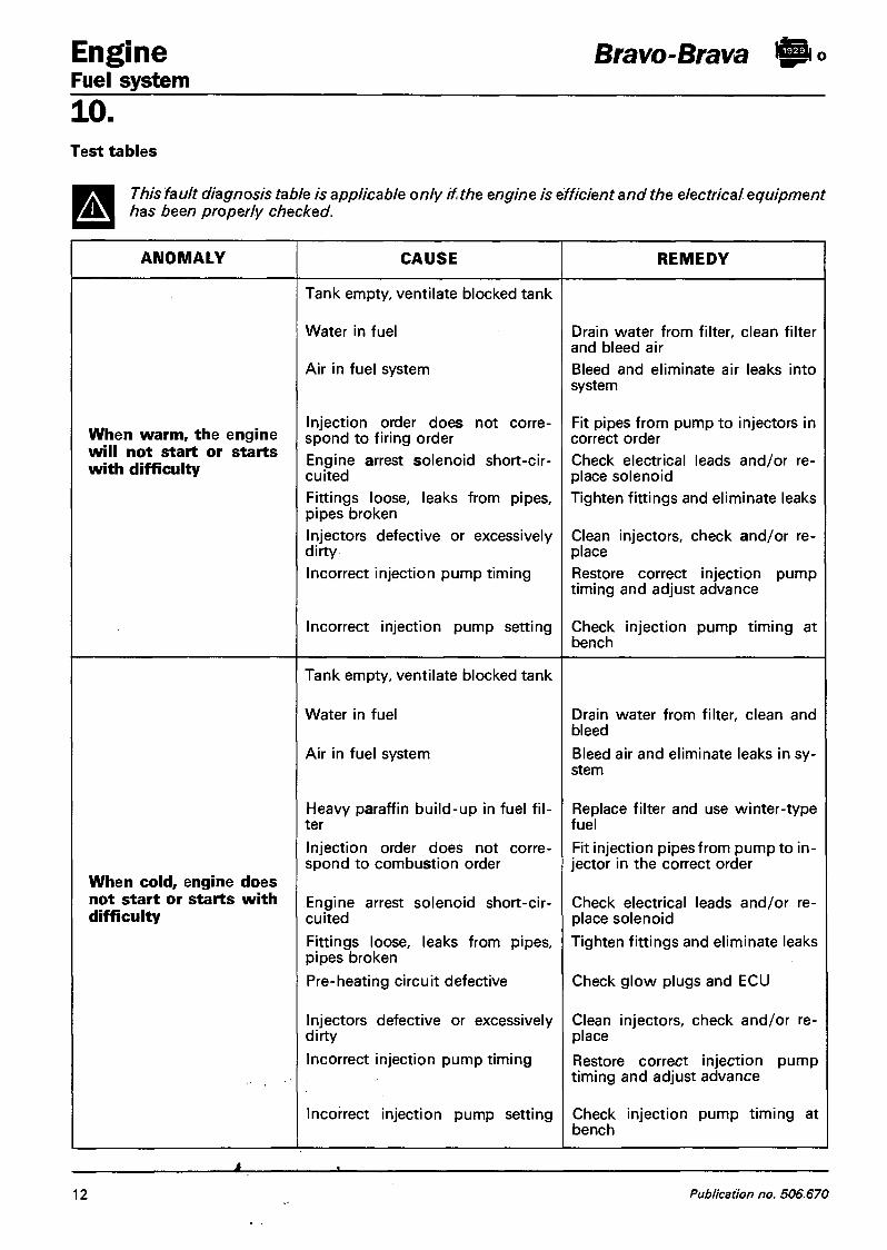
Engine Bravo-Brava fto Fuel system 10. Test tables
This fault diagnosis table is applicable only if the engine is efficient and the electrical equipment has been properly checked.
ANOMALY CAUSE REMEDY
When warm, the engine will not start or starts with difficulty
Tank empty, ventilate blocked tank
Water in fuel
Air in fuel system
Injection order does not correspond to firing order Engine arrest solenoid short-circuited Fittings loose, leaks from pipes, pipes broken Injectors defective or excessively dirty
Incorrect injection pump timing
Incorrect injection pump setting
Drain water from filter, clean filter and bleed air Bleed and eliminate air leaks into system
Fit pipes from pump to injectors in correct order Check electrical leads and/or replace solenoid Tighten fittings and eliminate leaks
Clean injectors, check and/or replace Restore correct injection pump timing and adjust advance
Check injection pump timing at bench
When cold, engine does not start or starts with difficulty
Tank empty, ventilate blocked tank
Water in fuel
Air in fuel system
Heavy paraffin build-up in fuel filter Injection order does not correspond to combustion order
Engine arrest solenoid short-circuited Fittings loose, leaks from pipes, pipes broken Pre-heating circuit defective
Injectors defective or excessively dirty
Incorrect injection pump timing
Incorrect injection pump setting
Drain water from filter, clean and bleed Bleed air and eliminate leaks in system
Replace filter and use winter-type fuel Fit injection pipes from pump to injector in the correct order
Check electrical leads and/or replace solenoid Tighten fittings and eliminate leaks
Check glow plugs and ECU
Clean injectors, check and/or replace Restore correct injection pump timing and adjust advance
Check injection pump timing at bench
1
12 Publication no. 506.670

Bravo-Brava !SPi° Eng ine Fuel system
10. ANOMALY CAUSE REMEDY
Engine misses when idling
Fuel outlet and inlet fittings on injection pump exchanged
Incorrect injection pump setting
Fit fittings correctly
Check injection pump setting at test bench
Injection order does not correspond to combustion order
Fit pipes from pump to injectors in correct order
Air in fuel system Bleed and eliminate air leaks into system
Uneven idling with engine warm Fittings loose, leaks from pipes,
pipes broken Tighten fittings and eliminate leaks
Injectors defective or excessively dirty
Clean injectors, check and/or replace
Incorrect injection pump setting Check injection pump setting at test bench
Tank ventilation defective Check tank ventilation
Fuel delivery and return lines on injection pump changed over
Fit fittings correctly
Air in fuel system Bleed and eliminate air leaks into system
Fuel filter blocked Replace filter
Engine runs irregularly or misses
Fittings loose, leaks from pipes, pipes broken
Tighten fittings and eliminate leaks
Fuel and injection lines blocked or restricted
Check lines: repair or replace
Water in fuel Drain water from filter
Incorrect injection pump timing Restore correct injection pump timing on test bench
Injectors defective or excessively dirty
Clean injectors, check and/or replace
Incorrect injection pump setting Check injection pump setting at test bench
Copyright Fiat Auto 13

Engine Bravo-Brava Fuel system 10.
ANOMALY CAUSE REMEDY
Tank ventilation defective Check tank ventilation
Injection order does not correspond to combustion order
Fit pipes from pump to injectors in correct order
Fuel delivery and return lines on injection pump changed over
Fit fittings correctly
Air in fuel system Bleed and eliminate air leaks into system
Engine not efficient (road performance unsatisfactory)
Fuel filter blocked
Fittings loose, leaks from pipes, pipes broken
Fuel and injection lines blocked or restricted
Replace filter
Tighten fittings and eliminate leaks
Check lines, repair or replace
Air cleaner blocked Replace filter element
Engine will not reach maximum rated speed
Adjust top speed by means of screw on injection pump
Injectors defective Check and/or replace injectors
Incorrect injection pump timing (delayed)
Restore correct injection pump timing and adjust advance
Incorrect injection pump setting Check injection pump setting at test bench
Injection order does not correspond to combustion order
Fit injection pump lines in correct order
Fittings loose, leaks from pipes, pipes broken
Tighten fittings and eliminate leaks
Excessive fuel consumption
Idle speed too high Adjust idle speed by means of screw on injection pump
Incorrect injection pump timing Restore correct injection pump timing and adjust advance
Incorrect injection pump setting Check injection pump setting at test bench
Engine will not stop Engine arrest solenoid short-circuited
Check electrical leads and/or replace solenoid
14 Publication no. 506.670

Bravo-Brava $<> Engine Fuel system
10. ANOMALY CAUSE REMEDY
Injection order does not correspond to combustion order
Fit pipes from pump to injectors in correct order
Air cleaner blocked Replace filter element
Black smoke at exhaust Injectors defective Check and/or replace injectors
Incorrect injection pump timing Restore correct injection pump timing and adjust advance
Incorrect injection pump setting Check injection pump setting at test bench
Tank ventilation defective Check tank ventilation
Fuel inlet and outlet lines changed over on injection pump
Fit fittings correctly
Air in fuel system Bleed and eliminate air leaks into system
Fuel filter blocked Replace filter
White smoke at exhaust Fuel and injection lines blocked or restricted
Check lines, repair or replace
- Injectors defective Check and/or replace injectors
Incorrect injection pump timing (delayed)
Restore correct injection pump timing and adjust advance
Incorrect injection pump setting Check injection pump setting at test bench
Air in fuel system Bleed and eliminate air leaks into system
Engine will not reach maximum rated rpm
Injectors defective Check and/or replace injectors
Incorrect injection pump timing (delayed)
Restore correct injection pump timing and adjust advance
Injectors defective Check and/or replace injectors
Excessive engine noise Incorrect injection pump timing (advance)
Restore correct injection pump timing and adjust advance
Incorrect injection pump setting Check injection pump setting at test bench
Copyright Fiat Auto 15
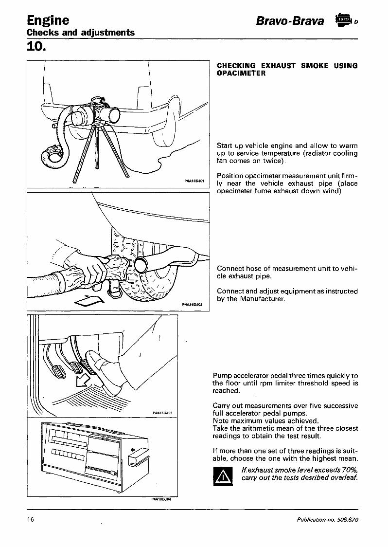
Engine Checks and adjustments
Bravo-Brava fti»
10. CHECKING EXHAUST SMOKE USING OPACIMETER
Start up vehicle engine and allow to warm up to service temperature (radiator cooling fan comes on twice).
Position opacimeter measurement unit firmly near the vehicle exhaust pipe (place opacimeter fume exhaust down wind)
Connect hose of measurement unit to vehicle exhaust pipe.
Connect and adjust equipment as instructed by the Manufacturer.
Pump accelerator pedal three times quickly to the floor until rpm limiter threshold speed is reached.
Carry out measurements over five successive full accelerator pedal pumps. Note maximum values achieved. Take the arithmetic mean of the three closest readings to obtain the test result.
If more than one set of three readings is suitable, choose the one with the highest mean.
If exhaust smoke level exceeds 70%, carry out the tests desribed overleaf. A
16 Publication no. 506.670

Bravo-Brava fto Engine Checks and adjustments
1
P4A17DJ01
Check air cleaner condition
3
b
Check valve clearance and/or timing
P4A17DJ05
Check injectors are perfectly clean
Numbers at top of i l lustrations indicate order of operat ions.
1 0 .
P4A17DJ02
Check injection pump timing and/or output
4
P4A17DJ04
Check injector setting
P4A17DJ06
Check compression ratio
Copyright Fiat Auto 17

Engine Fuel system
Bravo-Brava ft
10 . FUEL CIRCUIT DIAGRAM
NOTE Due to the specific shape of the tank, an air pocket will build up at the bottom fuel is added and prevent the tank being properly filled. Line (4) allows air to flow form the lower part to allow the tank to be completely filled.
1. Injection pump. 2. Fuel delivery line from filter to pump.
3. Excess fuel return line from pump to tank.
4. Air breather line. 5. Fuel tank. 6. Fuel delivery line from tank to filter. 7. Fuel filter. 8. Screw for draining water from fuel
filter. 9. Injectors.
18 Publication no. 506.670

Bravo-Brava ft Engine Fuel system
AIR INTAKE CIRCUIT DIAGRAM
1 0 .
1. Inlet manifold. 2. Upper resonator. 3. Air cleaner. 4. Lower resonator. 5. Inlet fitting.
Copyright Fiat Auto 19

t
Bravo-Brava Braking system Contents
33. page
HYDRAU LIC SYSTEM
- Diagram of hydraulic braking system (front disc brakes arid rear drum
v brakes) and mechanical handbrake system ' 1
- Brake pedal 2 - Brake fluid reservoir 3 - Brake pump 4 - Servo unit 5 - Vacuum unit 10
FRONT BRAKES
-Removing-refitting - Brake caliper - Brake discs - Brake pads - Bleeding
REAR BRAKES
- Drum brakes 15 - Automatic adjuster assembly for recov
ering shoe-drum clearance 19 - Brake drums - Shoes 20 - Wheel cylinders - Bleeding 21 - Diagram of hydraulic braking system
(front and rear disc brakes) and mechanical handbrake system 22
- Disc brakes 23 - Brake caliper 25 - Automatic adjuster assembly for recov
ering clearance between rear brake pads and discs and handbrake slack 27
- Brake discs 28 - Brake pads - Bleeding 29 - Brake pressure proportioning valve 31 - Handbrake 32
11 12 13 14
Copyright Fiat Auto
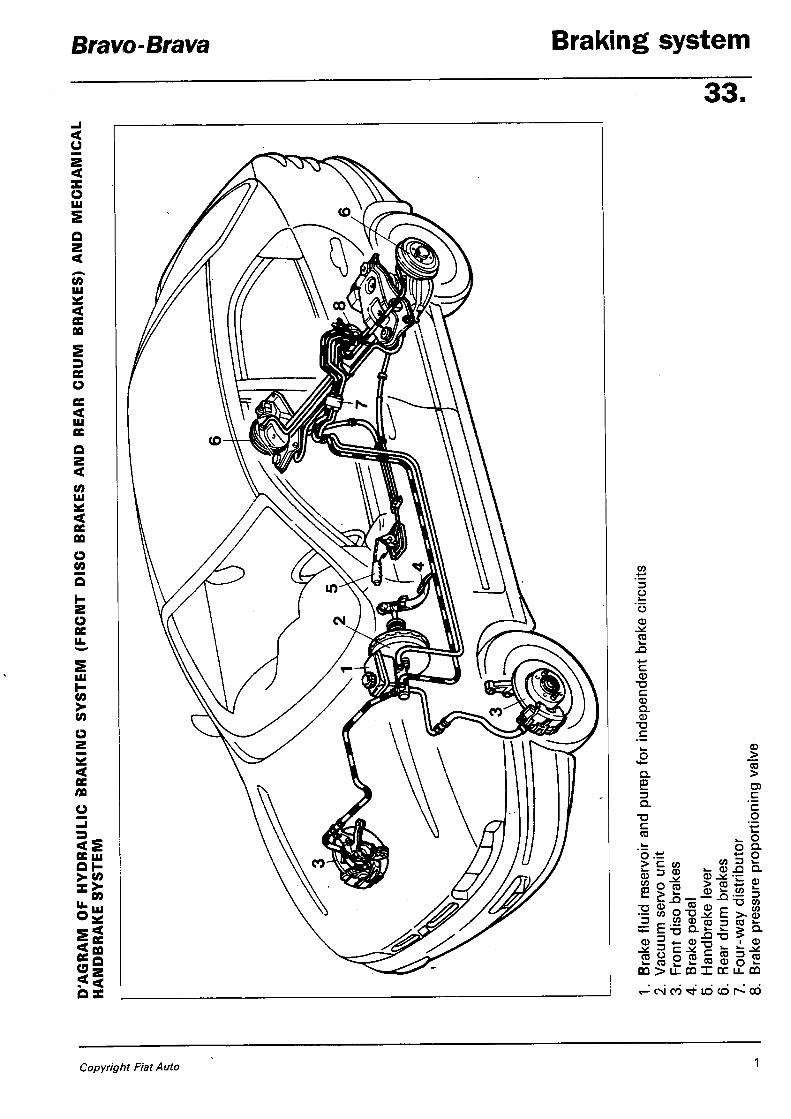
Bravo-Brava Braking sys tem
33.
u 2 < X o LU
( 0 LU
cc 00
ce o ce < LU CC < V) LU oc 00
o C O
o
oc s UJ
H > ( 0
o oc 00
CC UJ OH £?
C O
U M O X
CO
3 o CD
c CD
T3
c CD Q. o
TD c Q. £ Q.
T3 c cc
o .t; > c w
£ 5 2 •— co o
*" 1"° CD 5 *-(O " O >- IB ! :
00 > li
ce
to D
CO
T3 .2 2 CO
m x rr u- m CO CD
CD _> CO > C 'c o v» o Q. O Q. CD CO ^ w >- ©
CN 00 ^ - LO co 00
Copyright Fiat Auto 1

Braking system Hydraulic system
Bravo-Brava
33. BRAKE PEDAL
Removing - ref itti ng
To remove the brake pedal, proceed as follows: - remove the split pin and withdraw the ser
vo unit pushrod from the pin on the brake pedal;
raise the clutch pedal, undo the bolt and remove the brake pedal;
NOTE To refit the brake pedal, reverse the procedure for removal.
f^M Lubricate the parts concerned with grease before final assembly.
2 Publication no. 506.670

Bravo-Brava Braking s y s t e m Hydraulic system
33.
<I> BRAKE FLUID RESERVOIR
Checking low brake fluid level indicator
NOTE Periodically check the operation of the indicator by pressing on the top of the reservoir cover (as shown by the arrows); with the ignition ON, the braking system fault warning light should come on.
Removing - ref itti ng
To remove the brake fluid reservoir, proceed as follows: - disconnect the sensor connector and undo
the cap; - remove the brake fluid from the reservoir,
using the special syringe;
pull the reservoir upwards to remove it.
A Take care should any residual fluid emerge from the reservoir.
NOTE To refit the brake fluid reservoir, reverse the procedure for removal.
A Before filling the reservoir, make sure that it is thoroughly clean.
Bleed the hydraulic system
Copyright Fiat Auto 3

Braking system Bravo-Brava Hydraulic system 33.
BRAKE PUMP
Removing-refitting
To remove the brake pump, proceed as follows: - undo the brake pipe connectors using tool
1856132000, so as not to damage them;
P4A004D01
When overhauling the brake pump, replace the sealing rings; if there are traces of friction or seizure on the pump casing, replace the complete brake pump.
4 Publication no. 506.670

Bravo-Brava Braking sys tem Hydraulic operation
33
P4A005D01
Longitudinal section of brake pump
SERVO UNIT
Servo unit mounted on the car
Checking hydraulic pushrod recess using a depth gauge
NOTE The servo unit is adjusted using the adjustment screw located on the end of the rod. At the rest position, the end of the adjustment screw should be recessed by 22.45 - 22.65 mm in relation to the plane of the front cover.
P4A005D03
Copyright Fiat Auto 5

Braking system Hydraulic operation
Bravo-Brava
33.
Removing-refitting
To remove the servo unit, proceed as follows:
NOTE The arrows shows the sound-proofing panel. To facilitate dismantling, remove the accelerator pedal, whose attachment plate rests on the sound--proofing panel.
P4A006D03
disconnect the accelerator cable from its pedal;
undo the nuts and remove the attachment plate and the accelerator pedal;
6 Publication no. 506.670

Bravo-Brava Braking sys tem Hydraulic system
33.
remove the attachment buttons (1) and (2) on the sound-proofing panel;
NOTE The button (1) cannot be reused, so during assembly, after fitting the plate (3), a new button should be fitted.
A The sound-proofing panel need not be fully removed; it is sufficient to move it over to the right to permit access to the servo unit's attachment nuts.
withdraw the split pin to release the servo unit pushrod from the pin located on the pedal;
- undo the servo unit nuts (arrowed) from the pedal assembly mounting; '
Copyright Fiat Auto 1

Braking system Bravo-Brava Hydraulic system 33.
- undo the nuts securing the brake pump to the servo unit;
P4AOO8D01
- withdraw the brake pump complete wi th reservoir from the servo unit and rest it in the engine compartment to facilitate the removal-refitting of the servo unit;
P4AOO8D02
- disconnect the vacuum connection pipe (arrowed) and withdraw the servo unit from inside the engine compartment.
P4A0O8DO3
8 Publication no. 506.670

Braking sys tem Hydraulic system
33.
<t>
View of servo unit from attachment side to pedal assembly mounting
P4A009D01
22.45 - 22.65 mm
P4A009D02
Longitudinal section of Iso-Vac 8" servo unit
22.45 - 22.65 mm = Distance between hydraulic piston pushrod and brake pump contact plate. If necessary, adjust nut (1) to obtain correct adjustment of the servo unit.
Bravo-Brava
Copyright Fiat Auto 9

Braking system Bravo-Brava ftoftiTD
Hydraulic system 33.
VACUUM UNIT
Vacuum gauge with connections for checking operation of vane-type vacuum unit
P4A010D01
Checking operating faults
If the braking system is faulty, before replacing the vacuum unit, the vacuum circuit should be checked completely in accordance with the following procedure:
- with the engine off, empty the brake vacuum circuit fully by pressing the brake pedal to the floor several times;
- fit the vacuum gauge 1895899000 (3) between the one-way valve located on the vacuum unit (1) and the servo unit connecting pipe (2) (as shown in the drawing opposite);
- start the engine; after running the engine at idling speed for 20 seconds, the vacuum reading on the vacuum gauge (3) should be over 0.6 bar.
If the vacuum is under 0.6 bar, the servo unit connecting pipe (2) should be disconnected and the free end should be plugged with the special plug (4). Re-start the engine; after running the engine at idling speed for 20 seconds, the vacuum reading on the vacuum gauge should be over 0.6 bar. If it is, the fault should be sought in the air circuit or the servo unit. If not, the vacuum unit is faulty and should be replaced.
P4A010D03
10 Publication no. 506.670

Bravo-Brava Braking sys tem Front brakes
33. REMOVING-REFITTING
Dismantle the components of the braking system as described below: 1. disconnect the brake hose using tool
1856132000 on the connectors; disconnect the brake pad wear sensor wiring connector;
NOTE The hose must not be swollen or cracked, otherwise it must be replaced.
I V I A Wehn refitting the brake hose, check that the mounting rubber is positioned correctly to prevent the pipe coming into contact with the whee-larch or mechanical parts of the car, whatever the travel or turning angle of the wheels.
2. remove the retaining spring; 3. undo the bolts and remove the brake
caliper;
The caliper case attachment bolts are self-locking and should always be renewed whenever they are slackened or unscrewed.
4. remove the brake pads; 5. undo the bolts securing the caliper
mounting bracket and remove the latter.
Copyright Fiat Auto 11

Braking system Front brakes
Bravo-Brava
33. BRAKE CALIPER
Dismantling-reassembly
Place the caliper in a vice, fitting the protections, then proceed as described below:
1.
2. 3. 4.
direct a jet of compressed air into the brake fluid inlet hold in order to dismantle the piston from the caliper case; undo the air bleed screw and remove it; remove the seal; check the components; the piston and caliper case must not show signs of friction or seizure; if they do, the caliper complete with piston should be replaced. It is nevertheless always necessary to replace the dust excluder (1) and seal (2), and to check that the bleed screw (3) is not blocked.
A Use a solution of FIA T LDC detergent in hot water to wash the metal parts.
NOTE To refit the brake caliper, reverse the procedure for removal.
Lubricate the parts concerned with brake fluid before final assembly.
Before fitting the piston in the caliper case, fit the dust excluder on the rear end of the piston. Insert the piston gradually, taking care not to damage the dust excluder.
A
12 Publication no. 506.670

Bravo-Brava Braking s y s t e m Front brakes
33. BRAKE DISCS
Dismantling-reassembly
Undo the brake disc attachment bolts and remove the disc. When refitting, eliminate any traces of rust to ensure that the disc is perfectly perpendicular to the hub.
Checking and measuring disc thickness
The minimum permissible brake disc thickness after wear is indicated in the table; if the measured value is less than the value in the table, the disc should be renewed. In the case of damage or deep scoring, the brake disc surfaces can be skimmed; after skimming, the brake disc thickness must not be less than the value stated in the table;
Brake disc thickness (values in mm)
1370 12v 1581 16v 1929 D
1747 16v 1998 20v 1910TD
after wear 10.2 20.20
after skimming 11.1 20.55
Checking brake disc run-out
Also check that the run-out does not exceed 0.15 mm; this should be checked 2 mm from the disc's outer diameter.
Copyright Fiat Auto 13

Braking system Front brakes
Bravo-Brava
33.
<•> BRAKE PADS
Check
1. The brake pads must be renewed if the thickness of the friction material is less than 1.5 mm.
Check that brake pads of the same type are fitted to each pair of wheels.
BLEEDING
2. Manual bleeding.
The old brake fluid should not be reused. Top up the level with fresh brake fluid.
Bleeding with Jollyfren device
3. Connect the device's pipe to the brake fluid reservoir;
4. connect the device to the compressed air pipe and bleed the system as described in the device's instructions sheet.
P4AD14D03 P4A014D04
14 Publication no. 506.670

Bravo-Brava ft^vft l e v f t Braking s y s t e m Rear brakes
33. DRUM BRAKES
Removing - refitti ng
To dismantle the rear drum brakes, proceed as follows:
- undo the two bolts and remove the brake drum;
NOTE Before removing the brake drum, eliminate any traces of rust on the contact surfaces.
Copyright Fiat Auto 15

Braking system Bravo-Brava ftiavft^ft^
Rear brakes ^ 33.
sheath from the brake backplate;
16 Publication no. 506.670
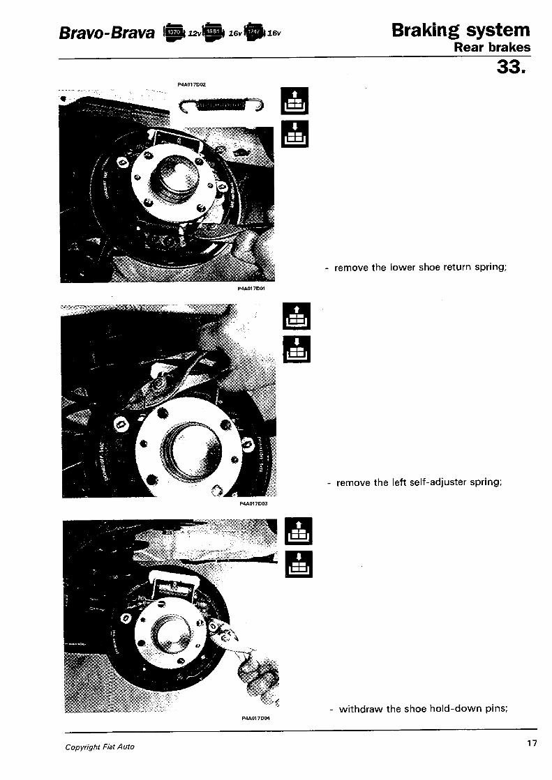
Bravo - Brava !{pi izvVBk i f t 16v Braking sys tem Rear brakes
33.
remove the lower shoe return spring;
remove the left self-adjuster spring;
- withdraw the shoe hold-down pins;
Copyright Fiat Auto 17

Braking system Rear brakes
Bravo-Brava Ip^Jcpi i 6 v f t 16v
33.
- remove the shoes;
P4A018D02
dismantle the self-adjuster from the right shoe.
< s > l A After refitting, adjust the handbrake by following the procedure described on page 32.
Rear brake components
1. Shoes 2. Lower shoe return spring 3. Shoe hold-down pin 4. Self-adjuster 5. Upper shoe return spring
NOTE The arrow shows the washer-clip which must be replaced whenever the shoes are replaced.
P4A018D04
18 XI-97 - Update Publication no. 506.670/13

Bravo-Brava ftizvfti i e v f t i e v Braking s y s t e m Rear brakes
33. AUTOMATIC ADJUSTER ASSEMBLY FOR RECOVERING SHOE-DRUM CLEARANCE
P4A019DQ1 sembly each time the brakes are operatee. should any adjustment be necessary at that moment. The device consists of a link rod ( 1 ) inside which an adjustment screw ( 2 ) freely slides. A ratchet wheel ( 3 ) is screwed onto this screw. In the rest position, the front shoe return spring ( 6 ) compresses the automatic adjuster assembly, so the ratchet wheel ( 3 ) pushes the frame ( 4 ) into contact wi th the end of the link rod ( 1 ) .
P4A019D03
The frame ( 4 ) is also subjected to a pushing force from the flexible blade ( 5 ) . During the braking action the two shoes move apart and come into contact wi th the drum; the two ends of the adjuster assembly are held in contact wi th the shoes by means of the springs ( 7 ) and ( 8 ) . The frame ( 4 ) is pushed by the flexible blade ( 5 ) against the ratchet wheel ( 3 ) , and by means of the pawl ( 9 ) (-permanently in contact with the ratchet wheel) , causes it to rotateCD. During brake release, the automatic adjuster assembly is again compressed by the action of the upper shoe return spring ( 6 ) ; the ratchet wheel ( 3 ) stops at the angle assumed during braking. This stop during rotation is caused by the friction between the frame ( 4 ) and the ratchet wheel ( 3 ) . Wi th the ratchet wheel ( 3 ) locked during rotation, if the brake linings are sufficiently worn from previous use of the brakes, the pawl ( 9 ) slips onto and engages with the next tooth LU. The maximum travel of the ratchet wheel ( 3 ) on the adjustment screw ( 2 ) is one tooth ( 0 . 0 2 0 - 0 . 0 2 5 mm). An exception to this is when the brakes bed in after dismantling, when the travel is two teeth ( 0 . 0 4 - 0 . 0 5 mm).
If after excessive braking the brakes overheat and the temperature reaches 1 0 0 ° - 1 1 0 ° C , the flexible blade ( 1 0 ) in the adjuster assembly comes into action by bending and locking the frame ( 4 ) in a neutral position [3.
During braking the ratchet wheel ( 3 ) is no longer subjected to the pushing action of the flexible blade ( 5 ) , so the pawl ( 9 ) assumes the same angle as the ratchet wheel too th , which wi l l be free to slide with the adjustment screw ( 2 ) on the pawl ( 9 ) without compensating for the distance created by the expansion of the drum. During overhaul, before fitting the brake linings, the ratchet wheel ( 3 ) of the adjuster assembly must be brought into contact w i th the spring ( 7 ) and then unscrewed by half a turn.
P4A019D04
Copyright Fiat Auto 19

Braking system Rear brakes
Bravo- Brava S i izvi&i ftiiev
33. BRAKE DRUMS
Checking and measuring brake drums
If the brake drums are deeply scored or are unevenly worn, they must be skimmed. The maximum permitted diameter increase on the brake drums is 0.8 mm.
<I>
Location on brake drum of hole for inspecting thickness of shoe friction material
<•> SHOES
Checking shoe
^The minimum permitted thickness of the brake lining is 1.5 mm.
20 Publication no. 506.670

Bravo-Brava l A t ^ i f i M ^ f t i 16v Braking sys tem Rear brakes
33. WHEEL CYLINDER
Removing-refitting
To remove the wheel cylinder, proceed as fo l lows: - using tool 1856132000, undo the brake
pipe connection; - undo the bolts and remove the wheel cyl in
der.
P 4 A 0 2 1 D 0 4
Checking wheel cylinder components
During overhaul, always replace the seals and dust excluders; if the cylinder barrel or pistons show faults, replace the assembly. Make sure that the bleed screw is not blocked.
BLEEDING
Do not re-use the old f luid. The level should be topped up w i th fresh brake f luid.
The rear brakes should be bled on a platform ramp with the rear suspension resting on the ground, so that the brake pressure proportioning valve enters into operation.
NOTE The brakes can also be bled using the Jollyfren device, using the procedure described for the front brakes.
Adjust the handbrake as described on page 32.
Copyright Fiat Auto XI-97 - Update 21

Braking system Bravo i g j j u o v

Bravo-Brava ft1 20v Braking sys tem Rear brakes
33. DISC BRAKES
Removing-refitting
To dismantle the rear disc brakes, proceed as follows:
- withdraw the retaining clip (1); - undo the hose connector using
tool 1856132000; P4A023O02
undo the screw (arrowed) to slacken the tension on the handbrake cable, in order to facilitate its disengagement;
release the handbrake cable;
Copyright Fiat Auto 2 3
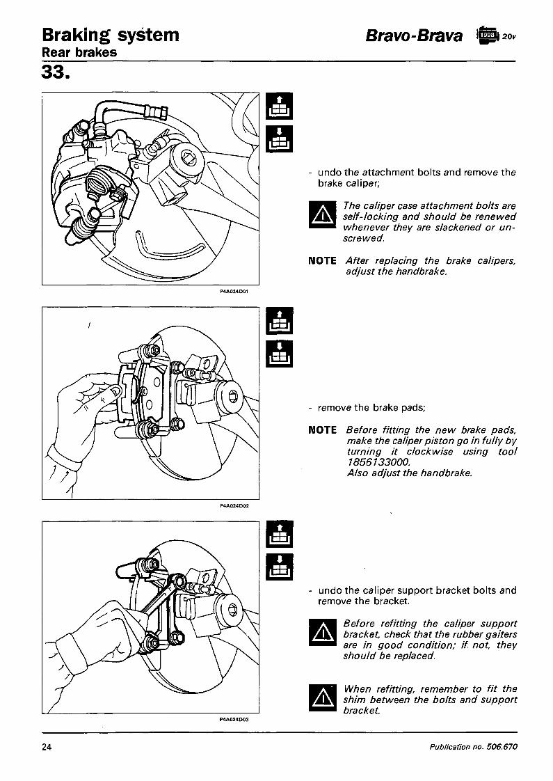
Braking system Rear brakes
Bravo-Brava \20v
33.
undo the attachment bolts and remove the brake caliper;
A The caliper case attachment bolts are self-locking and should be renewed whenever they are slackened or unscrewed.
NOTE After replacing the brake calipers, adjust the handbrake.
- remove the brake pads;
NOTE Before fitting the new brake pads, make the caliper piston go in fully by turning it clockwise using tool 1856133000. Also adjust the handbrake.
undo the caliper support bracket bolts and remove the bracket.
A
A
Before refitting the caliper support bracket, check that the rubber gaiters are in good condition; if not, they should be replaced.
When refitting, remember to fit the shim between the bolts and support bracket.
24 Publication no. 506.670

Bravo-Brava fti 20v Braking sys tem Rear brakes
33.
1 8 5 6 1 3 3 0 0 0
BRAKE CALIPER
Dismantling
Place the caliper in a vice, fitting the protections, then proceed as described below:
- undo the connector and remove the brake hose;
- undo the bleed screw and remove it;
NOTE The hose must not be swollen or cracked, otherwise it must be replaced. It is advisable to replace both hoses.
remove the piston and dust excluder using tool 1856133000;
remove the seal
Copyright Fiat Auto 25

Braking system Rear brakes
Bravo-Brava ft 20v
33. <•>
1856133000
Checking caliper assembly components
The piston and caliper case must not show signs of friction or seizure, otherwise the caliper complete with piston will need to be replaced. The dust excluder and seal should always be replaced; also make sure that the bleed screw is not blocked.
Use a solution of FIAT LDC detergent with hot water to wash the metal parts.
1. Caliper mounting bracket 2. Bleed screw 3. Caliper case 4. Seal 5. Dust excluder 6. Brake pads 7. Shim
Refitting
Fit the piston in the caliper case using tool 1856133000.
A Before fitting the piston in the caliper case, fit the dust excluder on the rear end of the piston.
Lubricate the parts concerned with brake fluid before final assembly.
Filling brake caliper
After overhauling the brake caliper and before fitting it to the car, it should be filled in accordance with the following procedure: - undo the bleed screw; - insert the end of a transparent tube in the
bleed screw hole; - using a normal container with brake fluid,
fill the caliper with fluid until air bubbles emerge from the threaded hole where the brake hose pipe is connected;
- lock the bleed screw. P4A026D02
26 Publication no. 506.670

Bravo-Brava ft a* Braking sys tem Rear brakes
33. AUTOMATIC ADJUSTER ASSEMBLY FOR RECOVERING CLEARANCE BETWEEN REAR BRAKE PADS AND DISCS AND HANDBRAKE SLACK
The rear brake caliper piston contains a device for automatically adjusting the distance between the disc and friction pads. This device consists of a nutscrew (2), which rotates on the shaft (5) only in the direction of advance because of the action of the Belleville washer (4) and a shaft (5), on which the nut-screw (2) is screwed. This shaft cannot rotate as it is secured to the caliper case by the retainer (6). The shaft and nutscrew are connected by a four-start threaded connection with a clearance (A) of a pre-established value.
During braking, the piston (1), pushed by hydraulic pressure, moves towards the brake pad with the nutscrew (2), the latter being secured to the piston by the retaining ring (3) and Belleville washer (4).
If the brake pads are excessively worn, the endfloat (A), even if recovered, is not sufficient to absorb by itself the entire travel of the piston (1). The nutscrew (2) then momentarily moves away from its point of contact with the piston (1), but the intervention of the Belleville washer (4) makes the nutscrew (2) rotate on the shaft (5) until it returns in contact with the piston (1).
When the handbrake is operated, the mechanical effort is transmitted from the lever to the link (7) and then, through the shaft-nutscrew connection, it reaches the piston (1) and from the latter to the brake pads.
The nutscrew (2), and thus the piston (1) joined to the latter, can rotate, since during the braking action the piston is engaged on the brake pad plate.
Cross section of rear brake caliper cylinder
1. Piston 2. Nutscrew 3. Retaining ring 4. Belleville washer
P4A027D01
5. Shaft 6. Retainer 7. Link A. Clearance between nutscrew and shaft
Copyright Fiat Auto 27

Braking system Rear brakes
Bravo-Brava ft**
33-BRAKE DISCS
Dismantling-reassembly
Undo the the bolts securing the brake disc and remove it; when refitting, eliminate any traces of rust to ensure that the disc is perfectly perpendicular to the hub.
Checking and measuring disc thickness
The minimum permissible brake disc thickness after wear is 9.20 mm; if the value is lower, the disc should be replaced. In the case of damage or deep scoring the brake disc surfaces can be skimmed; after skimming, the brake disc thickness must not be less than 10.10 mm.
Checking brake disc run-out
'Also check that the disc run-out does not exceed 0.15 mm. This value should be measured 2 mm from the disc's outer diameter.
28 \
Publication no. 506.670

Bravo-Brava fti 20v Braking sys tem Rear brakes
33.
<i> BRAKE PADS
Dismantling-reassembly
To replace the brake pads, proceed as fo l lows: 1. undo the bolts securing the brake caliper
to the mounting bracket and secure the brake caliper in an appropriate manner;
2. remove the brake pads.
The caliper case attachment bolts are self-locking and should be renewed whenever they are slackened or unscrewed.
A NOTE When refitting, make the caliper pis
ton go back in before fitting the brake caliper.
Checking brake pads The brake pads must be renewed when the thickness of the friction material is less than 1.5 mm. Check that brake pads of the same type are fitted on each pair of wheels.
Bleeding
The old f luid should not be reused. Top up the level w i th new brake f lu id. The brakes can also be bled using the J o l -lyfren device, fol lowing the procedure described for the front brakes.
P4A023D03
Copyright Fiat Auto 29

Braking system Rear brakes
Bravo-Brava
33.
BRAKE PRESSURE PROPORTIONING VALVE
Removing-refitting
To remove the brake pressure proportioning valve, proceed as follows: 1. disconnect the exhaust pipe end section
mounting; 2. disconnect the exhaust pipe intermediate
section mounting; 3. undo the bolts and remove the heat shield
from the exhaust pipe to facilitate access to the brake pressure proportioning valve;
4. uncrew the brake hose connections and disconnect the spring indicated;
The connectors fitted on the brake pressure proportioning valve are 11 and 13 mm; use the spanner 1856132000 for the 11 mm ones, and for the 13 mm ones use an open spanner taking care not to damage the connectors.
P4A030D04
30 Publication no. 506.670

Bravo-Brava Braking sys tem Rear brakes
33.
P 4 A 0 3 2 D 0 3 P 4 A 0 3 2 D 0 4
Handbrake lever
Removing - refitting
1. Working as illustrated on the preceding page, remove the lever cover and undo the adjustment nut underneath, then disconnect the wiring connector for the handbrake warning light switch.
2. Raise the car on the ramps and remove the heat shield illustrated.
3. Undo the bolts (arrowed), lower the car and remove the lever from its seating.
A Refit the dismantled parts in reverse order to removal, and then adjust the handbrake.
Handbrake cables
Removing - refitting
4. Working as described above, remove the lever cover, undo the adjustment nut, raise the ramps and remove the heat shield, then undo the bolts securing the handbrake cable to the bodyshell.
Copyright Fiat Auto XI-97 - Update 3 2 / 1

Braking system Rear brakes
Bravo-Brava
33.
1.2. Detach the cables from the handbrake control by undoing the points illustrated.
Remove the protective cover illustrated and release the handbrake cable from the anchor on the lever, then wi thdraw the sheath wi th the handbrake cable and remove it.
Refit the dismantled parts in reverse order to removal, and then adjust the handbrake.
Adjusting handbrake The handbrake cables are connected to a bracket which acts directly on the automatic adjuster. Whenever repairs are carried out on the rear brake which involve dismantling the cables, the cables must be adjusted to ensure the correct operation of the automatic adjuster.
Proceed as follows:
- Undo the handbrake cable adjustment nut two or three turns, to make sure that the cable is fully slack.
- Start the car with the gear lever in neutral, and with the engine idling, depress the brake pedal fully at least 30 times.
- Retighten the cable adjustment nut previously unscrewed, making sure that the rear wheels turn freely when the handbrake lever is at rest.
- Check that the braking action starts from the first or second notch, and then at the end of adjustment the lever does not engage more than five notches on the sector gear.
4A056D
32 /2 XI-97 - Update Publication no. 506.670/13

Bravo-Brava Braking sys tem Rear brakes
33.
P4A032D03
Handbrake lever
Removing - refitting
1. Working as illustrated on the preceding page, remove the lever cover and undo the adjustment nut underneath, then disconnect the wiring connector for the handbrake warning light switch.
2. Raise the car on the ramps and remove the heat shield illustrated.
3. Undo the bolts (arrowed), lower the car and remove the lever from its seating.
Refit the dismantled parts in reverse order to removal, and then adjust the handbrake.
Handbrake cables
Removing - refitting
Working as described above, remove the lever cover, undo the adjustment nut, raise the ramps and remove the heat shield, then undo the bolts securing the handbrake cable to the bodyshell.
Copyright Fiat Auto XI-97 - Update 32 /1

Braking system Rear brakes
Bravo-Brava
33.
P4A033D09
A
Detach the cables from the handbrake control by undoing the points illustrated.
Remove the protective cover illustrated and release the handbrake cable from the anchor on the lever, then wi thdraw the sheath with the handbrake cable and remove it.
Refit the dismantled parts in reverse order to removal, and then adjust the handbrake.
Adjusting handbrake The handbrake cables are connected to a bracket which acts directly on the automatic adjuster. Whenever repairs are carried out on the rear brake which involve dismantling the cables, the cables must be adjusted to ensure the correct operation of the automatic adjuster.
Proceed as follows:
- Undo the handbrake cable adjustment nut two or three turns, to make sure that the cable is ful ly slack.
- Start the car with the gear lever in neutral, and wi th the engine idling, depress the brake pedal ful ly at least 30 times.
- Retighten the cable adjustment nut previously unscrewed, making sure that the rear wheels turn freely when the handbrake lever is at rest.
- Check that the braking action starts from the first or second notch, and then at the end of adjustment the lever does not engage more than five notches on the sector gear.
4A056D
3 2 / 2 XI-97 - Update Publication no. 506.670/13
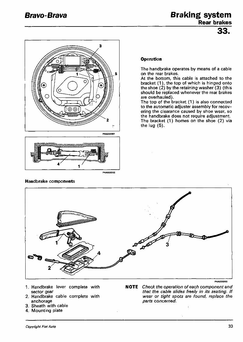
Bravo-Brava Braking sys tem Rear brakes
33.
Operation
The handbrake operates by means of a cable on the rear brakes. At the bottom, this cable is attached to the bracket (1), the top of which is hinged onto the shoe (2) by the retaining washer (3) (this should be replaced whenever the rear brakes are overhauled). The top of the bracket (1) is also connected to the automatic adjuster assembly for recovering the clearance caused by shoe wear, so the handbrake does not require adjustment. The bracket (1) homes on the shoe (2) via the lug (5).
Handbrake components
1. Handbrake lever complete with sector gear
2. Handbrake cable complete with anchorage
3. Sheath with cable 4. Mounting plate
NOTE Check the operation of each component and that the cable slides freely in its seating. If wear or tight spots are found, replace the parts concerned.
Copyright Fiat Auto 33


Bravo-Brava Braking system Contents
33. page
ANTI-LOCK BRAKING SYSTEM
- Introduction 1 - Method of operation of the TEVES
MK20 anti-lock braking system (A.B.S.) 1
- Components of the TEVES MK20 A.B.S. 4
- Diagram of braking system with anti-lock braking system 4
- Wiring diagram of TEVES M K20 A.B.S. 6
- Control unit 7 - Fault diagnosis 8 - Wheel rpm sensor 10 - Stop lights switch 11 - A.B.S. fault warning light 12 - Electrohydraulic control unit 12 - Hydraulic diagram of TEVES MK20
A.B.S. 13 - Description of hydraulic operation of
TEVES MK20 A.B.S. 14 - Requirements to be observed on cars
fitted with anti-lock braking system 19 - Precautions to be observed during re
pairs involving components of the anti-lock braking system 19
r Removing-refitting components of the anti-lock braking system 20
Copyright Fiat Auto

Bravo-Brava Braking s y s t e m Anti-lock braking system
33. INTRODUCTION
The braking system must be rated to take account of the weight of the vehicle when fully laden and the maximum tyre/ground grip coefficient that may be achieved, in order to bring about efficient slowing down or stopping in the shortest possible distance and under any driving condition. However, this is over-rated for the most common conditions of partial load and reduced grip. Applying the maximum braking force under those circumstances leads to the wheels locking immediately, resulting in a reduction in the grip-friction coefficient and deterioration of braking efficiency. In order to arrest the forward motion of a vehicle quickly and efficiently under any contingent situation, it is necessary to maintain the rolling state of the tyres, despite the fact that, because of design requirements, the braking force applied on the friction linings is often excessive in relation to the driving weight and normal grip coefficients. It is therefore necessary to prevent the wheels locking by means of an electronically-controlled anti-lock braking system which is incorporated in the vehicle's braking system. Since it is not possible to assess the grip conditions in advance, the braking efficiency has to be controlled only after the detection of any effects of initial skidding of the tyre caused by excessive braking force in relation to the grip coefficient present. This detection by special sensors leads to the modulation of the braking force by the action of a set of solenoids and recycling pumps which, driven by a control unit, act on the braking circuit.
METHOD OF OPERATION OF THE TEVES MK20 ANTI-SKID SYSTEM (A.B.S.)
The TEVES MK20 anti-lock braking system is incorporated in the vehicle's ordinary braking system in order to prevent the wheels locking during braking. Its operation is described briefly below.
Block diagram of Teves MK20 A.B.S.
1. Battery 2. Rpm sensor 3. Control unit 4. Diagnosis warning light 5. Relays 6. Recycling pump 7. Modulator 8. Brake pump 9. Servo unit
10. Brake calipers
Copyright Fiat Auto 1

Braking system Bravo-Brava Anti-lock braking system 33.
1. Actual vehicle speed 2. Vehicle reference speed 3. Peripheral wheel speed 4. Wheel acceleration/deceler
ation 5. Braking system pressure 6. Permissible acceleration
band 7. Permissible deceleration
I band P4A02AD01
The signals (alternating or analogue) sent by the rpm sensors to the electronic control unit are converted by the input amplifier into square-wave (or digital) signals. The frequency of these signals provides the control unit with the corresponding speed (3) and acceleration/deceleration (4) of the individual wheels. From the combination of the individual peripheral speeds of the wheels, a reference speed (2) is worked out which, constantly updated, provides an indication of the vehicle's actual speed (1).
The electronic control unit also has stored in its memory the deceleration/acceleration thresholds (6) and (7) which each individual wheel must not exceed. So by means of a systematic, continuous and very rapid comparison between the wheel's deceleration/acceleration values and those of the memorized band, the rolling of the tyres during braking is monitored.
When the driver presses the brake pedal, the wheels may decelerate to different extents. The slowing down or total stoppage of the vehicle with deceleration within the memorized permissible band, does not lead to any intervention of the system in terms of control. However, at the moment when excessive braking force causes the wheel speed to decrease in relation to the vehicle's reference speed, the system starts the deceleration calculation cycle (point A) .
If the deceleration threshold (7) is exceeded, the system intervenes by driving the solenoids to reduce the pressure (point B) . After the pressure reduction, and after the first instants in which the deceleration increases further because of the inertia of the system, the wheel which is no longer braked reverses the tendency to lock, so regaining speed. When the deceleration returns within the threshold (7), the intervention of the control system is modified, starting the pressure maintenance phase (point C.)
2 Publication no. 506.670

Bravo-Brava Braking sys tem Anti-lock braking system
33. If the wheel does not regain its speed within a pre-determined time (t), a new pressure reduction phase is started.
The wheel normally regains speed until it exceeds the reference speed; at this point a new braking cycle (point D) commences, characterized by the three regulation phases for reducing, maintaining or re-establishing on the brake calipers the pressure generated by the driver on the brake pedal.
The logic described is not fixed, but adapts to the dynamic behaviour of the tyres in accordance with the different grip coefficients and the relevant deceleration/acceleration thresholds at the various speeds.
The number and frequency of the correction interventions is determined by the dynamic behaviour of the chain consisting of the brake circuit and A.B.S. components, but even more so by the tyre/road surface grip coefficient.
During braking on dry tarmac, six-eight interventions per second can be reached; this frequency is considerably lower on ice or wet roads.
The electronic control unit controls the various phases, supplying pulses of different current intensity to the solenoids. It also ensures that both rear wheels are supplied with the same braking force applicable to the rear wheel which is most liable to lock, i.e. that with least grip on the ground (to ensure the best stability of the trajectory).
NOTE During the intervention cycle, the brake pedal moves slightly depending on the increase or reduction of the controlled pressure.
If a wheel is rolling with a flat tyre, the A.B.S. intervenes if necessary to control the braking.
The A.B.S. is also active during braking in reverse gear.
The intervention of the device usually ceases at speeds of under 2.75 km/h to permit complete locking of the wheels when the vehicle is stopped.
NOTE Since the parameters monitored by the control unit (wheel speed and acceleration) are influenced by the inertia of the wheel/tyre assembly, vehicles with the anti-lock braking system must only be fitted with the rims, tyres and brake linings recommended and chosen by the manufacturer.
If snow chains are fitted, the resulting rolling condition leads to signals which, suitably filtered in the control unit, do not exclude the anti-lock braking device in the event of driving on hard and compact snow.
In aquaplaning conditions, the electronic control unit detects from the rpm sensor a faulty condition even during ordinary driving, with no braking, as the driving wheels tend to rotate at a higher speed than the driven wheels.
This condition would cause the electronic control unit to carry out a regulation cycle which did not meet requirements; for this reason the anti-lock braking system temporarily switches itself off (for such a short time that the warning light does not necessarily come on) and switches itself on again as soon as the aquaplaning ceases.
Copyright Fiat Auto 3

Braking system Anti-lock braking system 33. COMPONENTS OF THE TEVES MK20 A.B.S.
P4A04AD01
The main components of the A.B.S. are:
- electrohydraulic unit (1) shown in the figure above which comprises the electronic control unit (A), the electrohydraulic control unit (B) which modulates the braking pressure to the brake calipers by means of eight solenoids (two per wheel) and a dual-circuit recycling pump (C);
- four wheel rpm sensors, one (5) for each front wheel and one (11) for each rear wheel, which measure the rotation speed of the wheels;
- a switch on the brake pedal (8) for detecting the braking condition; - a warning light (7) located on the instrument panel indicating when the A.B.S. system is working
(light goes out after a test) or not working (light stays on).
The system is completed by the hydraulic pipes, specific electrical wiring and a diagnostic socket for the F/L Tester (or Computerized Diagnostic Station). The presence of a fault causes the A.B.S. to be deactivated immediately. The fault information present can be read by connecting the Fiat/Lancia Tester or Computerized Diagnostic Station to the diagnostic socket.
Bravo-Brava
DIAGRAM OF BRAKING SYSTEM WITH ANTI-LOCK BRAKING SYSTEM
I Hydraulic circuit for front right and rear left brakes J J J J Hydraulic circuit for front left and rear right brakes
1. Electrohydraulic control unit 2. Brake pump 3. Servo unit 4. Brake fluid reservoir 5. Front wheel rpm sensors 6. Front disc brakes 7. Fault warning light
8. Stop lights switch 9. Handbrake lever
10. Brake pressure proportioning valve 11. Rear wheel rpm sensors 12. Rear drum brakes (excluding 1998 16v) 13. Rear disc brakes (1998 16v only)
4 Publication no. 506.670

Bravo-Brava Braking s y s t e m Anti-lock braking system
33
P4A05AD02
Copyright Fiat Auto 5

Brakes Wheel anti-lock system
Bravo-Brava
33. TEVES MK20 A.B.S. SYSTEM ELECTRICAL DIAGRAM
11
18*¬3*"
11 *• 4»"
1 *-17*-
2*¬10*"
24*¬8*-
13*-
9*¬25*-
12*. 23*¬16*"
+ *
1
2-^31
+ 3 i-F/LT 5 +30 A o
§ ——o o — ^ +30 — o
7 +15 -[ B hfe-t-o
1 0
18 3 11 4 1 17 2 10
1. Wheel speed sensors 2. Wheel speed sensor connector (viewed from insertion side) 3. Control unit ground 4. F / L Tester diagnosis socket 5. Fuse A (60A) 6. Brake pedal switch 7. Fuse B (10A) 8. Instrument panel with failure warning lamp 9. Connector interconnecting A B S wiring and dashboard
10. Pump motor 11. Control unit
NOTE The numbers printed inside boxes refer to the control unit pins.
6

Bravo-Brava Braking s y s t e m Anti-lock braking system
33. CONTROL UNIT
The electronic control unit (E.C.U.) consists of:
- input circuits for filtering, conditioning and digitizing the signals received from the system via wiring; - integrated logic circuits for processing signals and managing program memories; - specific data memory for the application for which it is intended; - output or power stages for driving, with sufficient current intensity, the regulating solenoids, recy
cling pump motor and fault warning light.
P4A07AD01
NOTE In the event of a fault, the complete assembly is supplied as a spare part, so the connector (B) must never be disconnected.
A. Socket for connector on cables between control unit and system
B. Connector for cables connecting recycling pump to control unit
Teves MK 20 A.B.S. control unit output pins
1. Rear right sensor earth 2. Rear left sensor earth 3. Front right sensor signal 4. Front left sensor signal 5. N.C. 6. N.C. 7. N.C. 8. Power earth 9. Supply from battery (+VB)
10. Rear left sensor signal 11. Front left sensor earth 12. Brake pedal switch 13. F/L Tester connection
14. N.C. 15. N.C. 16. System fault warning light 17. Rear right sensor signal 18. Front right sensor earth 19. N.C. 20. N.C. 21. N.C. 22. N.C. 23. Ignition switch supply (+15) 24. Power earth 25. Supply from battery (+VB)
Copyright Fiat Auto 1

Braking system Bravo-Brava Anti-lock braking system 33.
The control unit (1) is supplied: - directly from the battery (+VB) on pins
9 and 25, through a 60A fuse (2); - under ignition key (+15) on pin 23,
through a 10A fuse (3). P4A0SAD01
FAULT DIAGNOSIS
The system has a self-test function which checks if there are any faults on the following components:
- wheel rpm sensors (4 sensors); - input solenoids (4 solenoids); - output solenoids (4 solenoids).
If a malfunction is identified, the control unit's safety circuit excludes the A.B.S. system, nevertheless ensuring normal operation of the conventional braking system. When the A.B.S. system is switched off, this is'indicated to the driver by the warning light on the instrument panel coming on. For safety reasons, the electronic control unit, by means of two microprocessors, controls all the logic functions, its software and all the input signals. If the two microprocessors receive identical input signals, they supply identical output signals. If there is a logic discrepancy between input signals and output response over a certain period of time, the safety system detects the fault and the A.B.S. is de-activated. The electronic control unit also has a safety circuit which monitors the efficiency of the system before every start-up and during driving.
The safety circuit carries out the following self-tests: 1. after the ignition has been switched on and for about 2 seconds, it checks the operation of the control
unit, the relays which operate the solenoids and the connection of the sensors; 2. after the engine has started, as soon as the speed of 6 km/h is exceeded, it activates the solenoids and
recycling pump for an operating check; it also checks that the 4 speed signals are present; 3. whenever the speed of 24 km/h is exceeded, starting from a standstill, it checks that the 4 speed sig
nals are present; 4. during driving it continuously checks the peripheral speed of the wheels against the calculated refer
ence speed, it checks the memory conditions and supervises the operation of the two relays; 5. during driving it constantly checks the battery voltage.
8 Publication no. 506.670

Bravo-Brava Braking sys tem Anti-lock braking system
33
Jj • • Fj.
16 +15
Dl
NOTE The fault warning light is connected so that it is on if the connector is not connected to the control unit or if the wire (1) is shorting to earth. Supplied by the instrument panel, it is only off if the battery voltage reaches the wire (1) from the control unit interface.
D1 : protective diode D2 : LED R1 & R2 : load resistors
1) Positive from control unit pin 16 P4A09AD01
Diagnosis of the system with the F /L Tester is only feasible if the peripheral speed of the wheels is below 4 km/h, the battery voltage is over 7 Volts and the A.B.S. system is not operating. Full diagnosis of the system consists of the following three stages: 1. display of a set of operating parameters; 2. display of any errors that may be present and their deletion; 3. activation of the actuators (active diagnosis).
1. PARAMETERS DISPLAYED 2. PROCEDURE 3. PARTS ACTIVATED
Speed of the individual wheels State of recycling pump motor State of brake pedal switch State of fault warning light
Detection of faults Memorization of the error Deletion of the error
Input solenoids (4) Output solenoids (4) Fault warning light Recycling pump motor
Detection of faults This is carried out during performance of basic functions and diagnostic tests relating to the sensors/actuators.
Memorization of the error and structure of the error memory. The error type code and the error counter are memorized for each error in the order in which they arise. This parameter consists of the code of the last fault which has occurred and the relevant counter. The latter is set at 31 in the event of a fault, and subsequently decreased by 1 for every start-up and subsequent increase in speed to over 20 km/h which takes place without the fault.
Error deletion The error is deleted as follows: - by a command from the F/L Tester; - when the error counter reaches zero.
NOTE As the start-up of the procedure involves disabling the system, the fault warning light remains on throughout the duration of the procedure. The procedure is interrupted if the vehicle exceeds the speed of 10 km/h.
Copyright Fiat Auto 9

Braking system Anti-lock braking system 33.
P4A10AD01
Bravo-Brava
WHEELRPM SENSOR
The vehicle speed measurement system consists of a wheel or toothed crownwheel (phonic wheel) fitted on the hub or wheel axle, and a variable reluctance sensosr. This assembly generates an electrical signal whose frequency is proportional to the speed of rotation.
1. Brass bush 2. Permanent magnet 3. Plastic casing of the sensor 4. Winding or coil 5. Polar core 6. Toothed crownwheel or phonic wheel 7. Coaxial tw in cable
P4A10AD03
The signals are obtained from magnetic f low lines which close through the teeth of a metal toothed wheel facing the sensor, which rotates w i th the wheel. The passage from full to empty, due to the presence or absence of the tooth, causes a change in the magnetic f low sufficient to generate an induced alternating voltage, derived from the count of teeth located on a ring (or phonic wheel). Measuring the period gives the speed data, whi le comparing successive periods gives the wheel acceleration/deceleration data. The specified gap for obtaining correct signals, between the end of the sensor and the phonic wheel, must be 0.9 ± 0.4 mm. This gap is not adjustable so, if the gap is outside the tolerance limits, check the condit ion of the sensor and the phonic wheel.
1 0 Publication no. 506.670

Bravo-Brava Braking sys tem Anti-lock braking system
33.
If one or more phonic wheels break or become deformed, causing a difference in speed of 25% in relation to the reference speed, the electronic control unit switches off the device and switches on the fault warning light. The time for detecting the fault is about 120 seconds with a vehicle speed of over 6 km/h.
NOTE Whenever fitting an rpm sensor, smear it with water-repellent grease, otherwise it could be damaged during subsequent withdrawal as a result of temperature variations over a period of time.
STOP LIGHTS SWITCH
The signal that the brake pedal has been operai switch (1) controlling the stop lights to pin 12.
P4A11AO03
reaches the control unit by the connection of the
This information is useful not only for controlling braking, but also under particular conditions, for example if sudden acceleration which makes the wheels skid is followed by heavy braking, or in the case of rough road surfaces (bumps etc.) which could cause variations in wheel speed for reasons not associated with the braking in progress.
Under these conditions the microprocessors work out a strategy linked to the changes in wheel speed at these moments, ensuring that braking is within correct parameters. As these are particular circumstances of braking control, the efficiency of the system is not impaired if the brake pedal switch is not connected to the control unit. For this reason it is not indicated by the warning light coming on, nor is the A.B.S. disabled.
Copyright Fiat Auto 11

Braking system Anti-lock braking system
Bravo-Brava
33. A.B.S. FAULT WARNING LIGHT
Under normal operating conditions, the red warning light (arrowed) is off.
During starting, when the ignition is switched on, the control unit carries out a static self-last lasting about 2 seconds, during which time the warning light stays on.
If there are no faults after this time, the warning light goes out. During driving, the control unit carries out continuous self-tests. If an error is recognized, the warning light comes on and the A.B.S. is disabled, wi thout affecting the operation of the conventional braking system.
NOTE If the battery has insufficient charge, the warning light and the A.B.S. may be excluded (for example in towns, travelling at low engine speeds, with all the electrical devices switched on).
ELECTROHYDRAULIC CONTROL UNIT
The electrohydraulic control unit is connected to the brake pump and brake caliper cylinders by brake pipes and is incorporated in the electronic control unit. Its purpose is to vary the pressure of the brake fluid in the brake caliper cylinders in accordance wi th the control signals coming from the electronic control unit. It consists of eight two-way solenoids ( two for each hydraulic circuit) and a dual-circuit recycling pump all driven by the electronic control unit. In particular, the pump enables brake f luid to be recovered during the pressure reduction phase, making it available again upstream of the solenoids for the subsequent pressure increase phase.
The accumulators allow brake fluid to be absorbed during the pressure reduction phase.
NOTE The electrohydraulic control unit cannot be overhauled. If found to be faulty, it must be fully replaced. The spare part is supplied filled with brake fluid (DOT 4). The braking system is bled in the same way as a conventional system.
o o o o AS PD PS AO o CP A cs o
Name Colour Connector
CP Pump primary M 1 2 x 1 AS Front left YELLOW M12x1 PD Rear right BLUE M10x1 PS Rear left RED M12x1 AD Front right GREEN M10x1 CS Pump secondary - M 1 2 x 1
NOTE The colour is also shown on the relevant pipe.
12 Publication no. 506.670
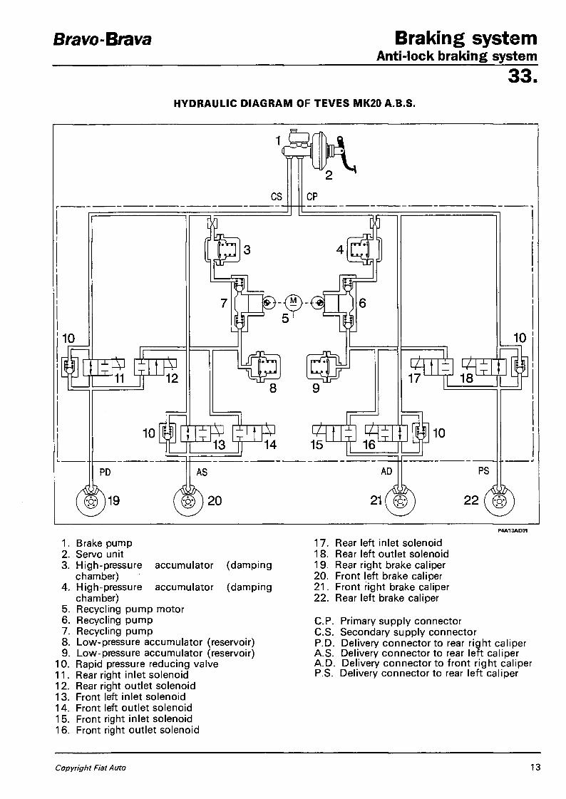
Bravo-Brava Braking sys tem Anti-lock braking system
33. HYDRAULIC DIAGRAM OF TEVES MK20 A.B.S.
P4A13AD01
1. Brake pump 2. Servo unit 3. High-pressure accumulator (damping
chamber) 4. High-pressure accumulator (damping
chamber) 5. Recycling pump motor 6. Recycling pump 7. Recycling pump 8. Low-pressure accumulator (reservoir) 9. Low-pressure accumulator (reservoir)
10. Rapid pressure reducing valve 11. Rear right inlet solenoid 12. Rear right outlet solenoid 13. Front left inlet solenoid 14. Front left outlet solenoid 15. Front right inlet solenoid 16. Front right outlet solenoid
17. Rear left inlet solenoid 18. Rear left outlet solenoid 19. Rear right brake caliper 20. Front left brake caliper 21. Front right brake caliper 22. Rear left brake caliper
C P . Primary supply connector C S . Secondary supply connector P.D. Delivery connector to rear right caliper A.S. Delivery connector to rear left caliper A.D. Delivery connector to front right caliper P.S. Delivery connector to rear left caliper
Copyright Fiat Auto 13

Braking system Bravo-Brava Anti-lock braking system 33.
DESCRIPTION OF HYDRAULIC OPERATION OF TEVES MK20 A.B.S.
Rest position
P4A14A001
1. Electronic control unit 8. Rapid pressure reducing valve 2. Low-pressure accumulator (reservoir) 9. Inlet solenoid (A) open (B) closed 3. Recycling pump motor 10. Outlet solenoid (A) closed (B) open 4. Recycling pump 11 . Brake caliper 5. High-pressure accumulator (damping 12. Rpm sensor
chamber) 13. Phonic wheel 6. Brake pump 14. Constriction 7. Servo unit
The Teves MK20 A.B.S. has two two-way solenoids for each hydraulic circuit. When de-activated (not earthed by the control unit) , the inlet solenoid (9) is in the open posit ion, thus allowing fluid to pass to the brake caliper. The pressure is maintained by closing this valve, i.e. supplying it electrically. When de-activated (not earthed by the control uni t ) , the outlet solenoid (10) is in the closed position and does not allow f luid to discharge to the low-pressure accumulator (2) . The accumulators (2) and (5) temporarily store the brake f luid which becomes available during the pressure reduction phase. The recycling pump (4) sends the brake fluid, wh ich f lows from the brake calipers during the pressure reduction phase, to the brake pump through the relevant accumulator. On the basis of the signals received from the rpm sensors located on the front and rear wheels, the electronic control unit drives the electrohydraulic control unit which in turn varies the pressure of the brake f luid sent to the caliper in accordance w i th three phases: increase, maintenance or reduction of pressure.
14 Publication no. 506.670

Bravo-Brava Braking sys tem Anti-lock braking system
33. Presssure increase phase
P4A15AD01
1. Electronic control unit 8. Rapid pressure reducing valve 2. Low-pressure accumulator (reservoir) 9. Inlet solenoid (A) open (B) closed 3. Recycling pump motor 10. Outlet solenoid (A) closed (B) open 4. Recycling pump 11. Brake caliper 5. High-pressure accumulator (damping 12. Rpm sensor
chamber) 13. Phonic wheel 6. Brake pump 14. Constriction 7. Servo unit
When the driver presses the brake pedal, the pressure generated by the brake pump (6) reaches the brake calipers without undergoing variations, as the solenoids (9) and (10) of the hydraulic unit are not earthed by the electronic control unit.
When the braking force increases, the wheel deceleration consequently increases: this causes faster deceleration of the car (i.e. the wheel slip increases). The slip value must not exceed a particular value beyond which the wheel loses grip with the ground and begins to skid, resulting in loss of direction control and increase in braking distances.
The wheel speed sensor (12) indicates when deceleration values which could impair the wheel's grip on the ground are reached; at this point the electronic control unit (1) drives the solenoids on the electrohydraulic control unit, reducing the braking force and allowing the wheel to increase its speed and so recover grip.
Copyright Fiat Auto 15

Braking system Bravo-Brava Anti-lock braking system 33. Pressure maintenance phase
P4A16A001
1. Electronic control unit 8. Rapid pressure reducing valve 2. Low-pressure accumulator (reservoir) 9. Inlet solenoid (A) open (B) closed 3. Recycling pump motor 10. Outlet solenoid (A) closed (B) open 4. Recycling pump 11 . Brake caliper 5. High-pressure accumulator (damping 12. Rpm sensor
chamber) 13. Phonic wheel 6. Brake pump 14. Constriction 7. Servo unit
In this phase the electronic control unit (1) earths the inlet solenoid (9) wh ich closes, whi le the outlet solenoid (10), not being connected to earth, is already closed.
The hydraulic connection between the brake pump (6) and brake caliper (11) is interrupted (wait ing position). The pressure in the brake caliper (11) is kept constant at the value reached previously, whatever the pressure on the brake pedal.
Even though the braking force maintains a continuous slowing down action, the wheel varies its speed in accordance with the grip on the ground, until the rpm sensor (12) measures a value which is comparable to the reference speed calculated by the electronic control unit (1). At this point, the control unit passes from the maintenance phase to the pressure increase phase (if the wheel accelerates) or reduction phase (if the wheel is tending to lock).
16 Publication no. 506.670

Bravo-Brava Braking sys tem Anti-lock braking system
33. Pressure reduction phase
P4A17AO01
1. Electronic control unit 8. Rapid pressure reducing valve 2. Low-pressure accumulator (reservoir) 9. Inlet solenoid (A) open (B) closed 3. Recycling pump motor 10. Outlet solenoid (A) closed (B) open 4. Recycling pump 11. Brake caliper 5. High-pressure accumulator (damping 12. Rpm sensor
chamber) 13. Phonic wheel 6. Brake pump 14. Constriction 7. Servo unit
The electronic control unit (1) detects the wheel's tendency to lock and activates the* electrohydraulic unit to limit the wheel deceleration to within the permitted threshold values. The electronic control unit (1) earths the inlet solenoid (9) and outlet solenoid (10). The inlet solenoid (9) remains closed, maintaining the break in connection between brake pump (6) and brake caliper (11); the outlet solenoid (10) opens thus hydraulically connecting the brake caliper (11) to the low-pressure accumulator (2) and recycling pump (4), in order to remove some of the fluid from the brake caliper (11) and reduce the pressure on that caliper. At the same time the electronic control unit (1) supplies the motor (3) for driving the recycling pump (4) which returns fluid removed from the brake caliper (11) into the main circuit. The accumulator (2) or low pressure reservoir present in the circuit stores some of the brake fluid removed from the calipers. Through the circuit of the recycling pump (4), the brake fluid is drawn in and sent, through the damping chamber (5) and constriction (14), into the main circuit of the brake pump (6). During this phase, a series of pressure waves (or hydraulic thrusts) is generated, and these are attenuated by the presence of the damping chamber (5) and constriction (14). During this phase, because of the reduction in the braking force, the wheel tends to assume the reference speed calculated by the electronic control unit (1)-
Copyright Fiat Auto 17

Braking system Bravo-Brava Anti-lock braking system 33. The braking is therefore intermittent or in steps, and fol lows a succession of phases dictated by the rolling conditions of the braked wheel in accordance wi th a repetitive cycle in the form of jerks. This is not perceived by the driver, because of the speed and frequency with which it takes place and because it is regulated by the inertia of the wheel which, in relation to the speed of intervention of the device, prevents the wheel from reaching extreme skid coefficients. On a car with no A.B.S., the driver is able to intervene intermittently on the brake pedal wi th a frequency of 2 cycles per second (2 presses and 2 releases). With the A.B.S. system, the cycles increase to 4-10 per second (depending on the grip). The intervention of the A.B.S. usually ceases at speeds of less than 2.75 km/h to permit complete locking of the wheels wi th the car stopped.
NOTE The recycling pump is of the dual-circuit free piston type, and is driven by an electric motor which is always turning during recycling. The pistons are not coupled to the electric motor, but are only moved along their travel, by the cam, when the brake fluid arrives. The pump can therefore only accomplish one pushing travel, and cannot draw in fluid because there is no mechanical connection between motor and pump.
Release of brake pedal
P4A18AD01
1. Electronic control unit 8. Rapid pressure reducing valve 2. Low-pressure accumulator (reservoir) 9. Inlet solenoid (A) open (B) closed 3. Recycling pump motor 10. Outlet solenoid (A) closed (B) open 4. Recycling pump 11. Brake caliper 5. High-pressure accumulator (damping 12. Rpm sensor
chamber) 13. Phonic wheel 6. Brake pump 14. Constriction 7. Servo unit
To permit a rapid reduction in pressure on the brake caliper (11) when the brake pedal is released, the system has a non-return valve (8) located in parallel w i th the inlet solenoid (9).
1 8 Publication no. 506.670

Braking s y s t e m Anti-lock braking system
33. REQUIREMENTS TO BE OBSERVED ON CARS FITTED WITH ANTI-LOCK BRAKING SYSTEM
Before carrying out welding work with electric welders, disconnect the connector from the electronic control unit. If the battery is removed, after refitting it make sure to tighten the terminals fully.
To replace the electronic control unit, removee the entire hydraulic unit for space reasons and in order not to damage the internal connector. Before dismantling the electrohydraulic control unit, disconnect the battery's negative lead.
The entire A.B.S. system must be checked with the Fiat/Lancia Tester whenever the electrohydraulic unit, an rpm sensor, the electronic control unit or wiring is replaced. After every intervention on the hydraulic circuit of the A.B.S. or braking system, fill the system with DOT 4 brake fluid, bleed the air out and check that there are no leaks from the connecting points.
The electrohydraulic control unit is supplied filled with DOT 4 brake fluid and the solenoids not supplied. The system is bled and filled with brake fluid in the same way as a conventional braking system, although it takes longer. Check that the pipes are not in contact with the bodywork at any point, in order to avoid not only the risk of damaging the pipe protection, but also the transmission of noise during operation of the A.B.S.
If connecting pipes have to be slackened or removed, leak tests must be conducted on the A.B.S. system.
Bravo-Brava
Do not put mineral oil in the brake circuit, as this would damage all the seals. If it is put in accidentally, the following must be replaced: - hydraulic unit; - brake pump; - calipers.
PRECAUTIONS TO BE OBSERVED DURING REPAIRS INVOLVING COMPONENTS OF THE ANTI-LOCK BRAKING SYSTEM
After any repair which has involved the electrical system of the anti-lock braking system or the rpm sensors, during either specific interventions or operations for the dismantling and replacement of mechanical parts (for example spring-damper assembly, constant velocity joints, drive shafts and wheel hubs), a very short road test should be carried out as follows: 1. increase the car speed to over 12 km/h and maintain this speed, in order to allow the electronic con
trol unit to conduct a dynamic check on the sensors and detect any faults, insecure contacts, incorrect positions or the absence of a phonic wheel;
2. after carrying out the above operation, if the warning light does not indicate a fault, continue the test at a speed of 50-60 km/h for 10 minutes, using the brakes normally but without braking sharply. This stage of the test enables the electronic control unit to recognize the presence of an incorrect phonic wheel.
Copyright Fiat Auto 19

Braking system Anti-lock braking system
Bravo-Brava
33.
REMOVING-REFITTING COMPONENTS OF THE ANTI-LOCK BRAKING SYSTEM
Electrohydraulic control unit
To remove the electrohydraulic unit, proceed as follows:
1. undo the clips securing the inlet pipe; 2. undo the clip securing the oil vapour recir
culation pipe and remove the complete inlet pipe;
remove the battery then undo the bolts indicated and move aside the battery cage;
20 Publication no. 506.670

Bravo-Brava Braking sys tem Anti-lock braking system
33.
disconnect the sensor connector on the brake fluid reservoir cap and unscrew the cap;
remove the brake fluid f rom the reservoir using the special syringe;
A Take care should residual fluid in the reservoir come out.
undo the bolts and move aside the brake f luid reservoir;
A Ensure that the reservoir is absolutely clean before filling it.
Bleed the hydraulic system
P4A21AO03
Copyright Fiat Auto 21
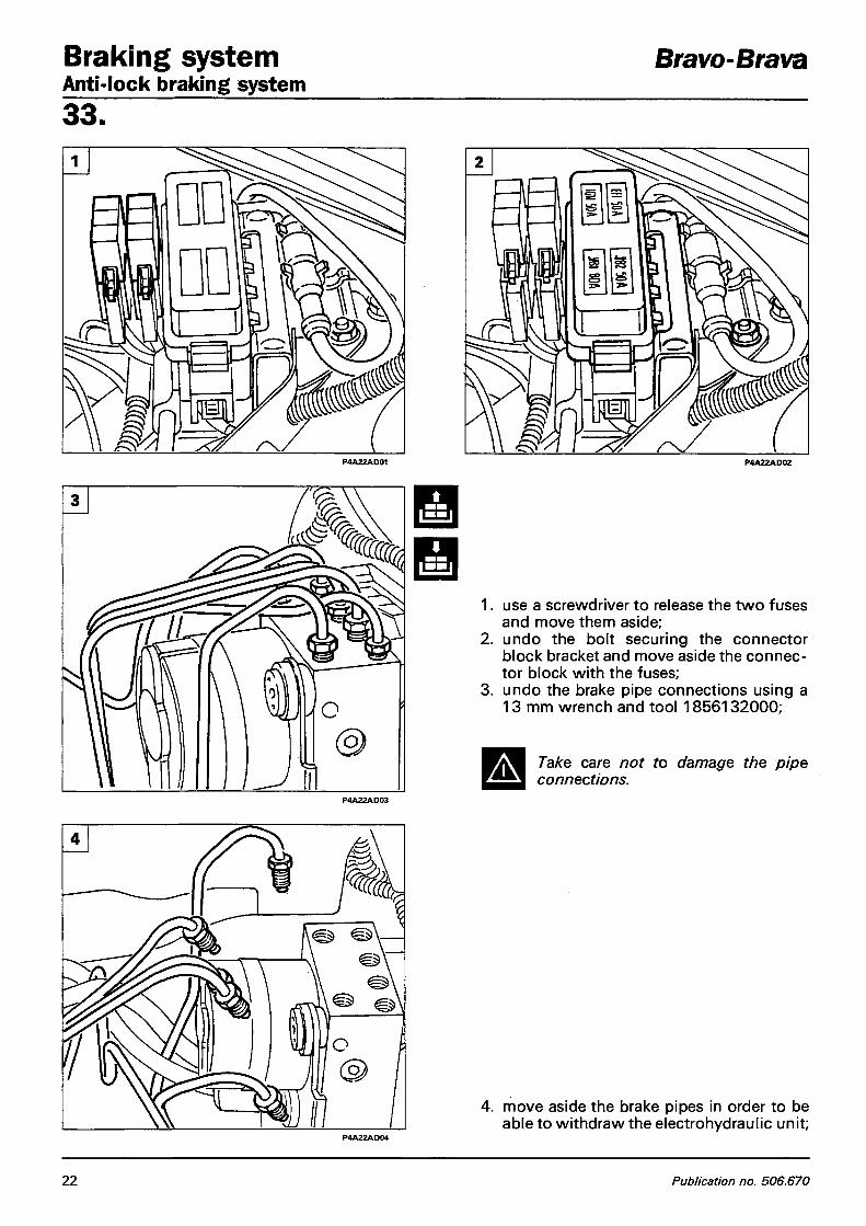
Braking system Anti-lock braking system
Bravo-Brava
33.
3.
use a screwdriver to release the two fuses and move them aside; undo the bolt securing the connector block bracket and move aside the connector block with the fuses; undo the brake pipe connections using a 13 mm wrench and tool 1856132000;
A Take care not to damage the pipe connections.
P4A22AD03
move aside the brake pipes in order to be able to withdraw the electrohydraulic unit;
22 Publication no. 506.670

Bravo-Brava Braking sys tem Anti-lock braking system
33.
1. undo the front bolt (1) and remove the side bolt (2);
2. disconnect the connector, pulling the hooking device (3) upwards and remove the electrohydraulic unit;
3. undo the screws shown and detach the mounting bracket from the electrohydraulic unit.
NOTE To refit reverse the procedure for removal.
Electrohydraulic control unit
Copyright Fiat Auto 23

Braking system Anti-lock braking system
Bravo-Brava
33.
Front wheel speed sensor
To remove the front wheel speed sensor, proceed as follows:
- disconnect the electrical connector;
undo the bolt and remove the sensor.
0.645 -1.305 mm
Checking gap between wheel speed sensor and phonic wheel on front wheel constant velocity joint
A The gap is not adjustable since no shims are supplied for the purpose. If the value measured is outside the specified tolerance limits, check the condition of the sensor and the teeth on the phonic wheel.
24 Publication no. 506.670

Bravo-Brava Braking sys tem Anti-lock braking system
33.
Rear wheel speed sensor
To remove the rear wheel speed sensor, proceed as fol lows:
1. remove the rear seat and lift the sound¬-proofing tr im;
2. disconnect the sensor's connector.
Raise the vehicle, then: 3. undo the bolts securing the fuel filter cov
er;
4. take out the rubber seal and wi thdraw the sensor cable;
Copyright Fiat Auto 25

Braking system Anti-lock braking system
Bravo-Brava
33.
undo the bolt and remove the sensor. P4A26AD01
12V ipp i6v mm i6v
D mBjt TD
Checking gap between wheel speed sensor and phonic wheel on res»* wheel hub
20V
The gap is not adjustable since no shims are supplied for the purpose. If the value measured is outside the specified tolerance limits, check the condition of the sensor and the teeth the phonic wheel.
26 Publication no. 506.670

Bravo-Brava Steer ing Contents
4 1 . page
UPPER STEERING SYSTEM
- Steering wheel 1 - Stalk unit base 2 - Steering column 3 - Ignition switch block 4
STEERING GEAR
- Variable ratio rack-and-pinion steering ' gear 5 - Operation 6
POWER-ASSISTED STEERING
- Description and operation 9 - Front wheel toe-in 11
RACK/PINION POWER STEERING GEAR
- Rack-and-pinibn power steering gear 12
POWER STEERING PUMP
- 1370 12v engine 17 - 1581 16v engine 20 - 1747 16v engine 22 - 1998 20v engine 25 - 1929 D engine 27 - 1910 TD engine 29
Copyright Fiat Auto

Bravo-Brava Steer ing Upper steering system
4 1 . STEERING WHEEL
Removing-refitting
To remove the steering wheel, proceed as follows: 1. use a screwdriver to remove the horn cov
er;
2. disconnect the horn wiring connectors; 3. undo the nut securing the steering wheel
to the steering column, then remove the steering wheel.
To remove the steering wheel on vehicles fitted with AIR BAG, see the procedure described in Section 55.
Copyright Fiat Auto 1

Steer ing Upper steering system
Bravo-Brava
4 1 .
STALK UNIT BASE
Removing-refitting
To remove the stalk unit base, proceed as follows: 1. undo the bolts arrowed and remove the
steering column bottom shroud; 2. undo the bolts arrowed and remove the
steering column top shroud; 3. using an Allen key, undo the screw on the
attachment collar of the stalk unit base and withdraw the collar;
4. disconnect the wiring connectors of the stalk unit base, and remove it.
2 Publication no. 506.670

Bravo-Brava S teer ing Upper steering system
4 1 . STEERING COLUMN
Removing-refitting
To remove the steering column, proceed as follows: 1. remove the bolt securing the lower steer
ing column to the steering pinion; P4A003F01
P4A003F03 P4A0O3FO4
Copyright Fiat Auto 3

Steering Upper steering system
Bravo-Brava
4 1 . IGNITION SWITCH BLOCK
Dismantling-refitting
To remove the ignition switch block, proceed as follows:
1. use a punch to undo the shear bolts locking the ignition switch block mounting;
2. remove the ignition switch block;
3. dismantle the ignition switch and lock from the block.
NOTE When refitting, use new shear bolts and tighten them until the hexagonal head shears off.
4 Publication no. 506.670

Bravo-Brava fti2v S teer ing Steering gear
4 1 . VARIABLE RATIO RACK-AND-PIIMIOIM STEERING GEAR
Removing-refitting
To remove the steering gear, proceed as follows: 1. remove the bolt securing the lower col
umn to the steering gear pinion; P4A003F01
P4A005F02
2. disconnect the transfer linkage from the gearchange control linkage.
Raise the vehicle, remove the front wheels, then working from both sides: 3. undo the nuts securing the right and left
tie-rods from the front vertical links; 4. use tool 1847035000 to prise off the
tie-rod heads from the two vertical links;
P4AOOSF03
Copyright Fiat Auto 5

Steering Bravo-Brava Steering gear 41 .
- prise off the gearchange control lever from the head on the steering gear;
P4A006F01
- undo the bolts securing the steering gear to the steering subframe;
P4A0O6F02
P4A006F03
6 Publication no. 506.670
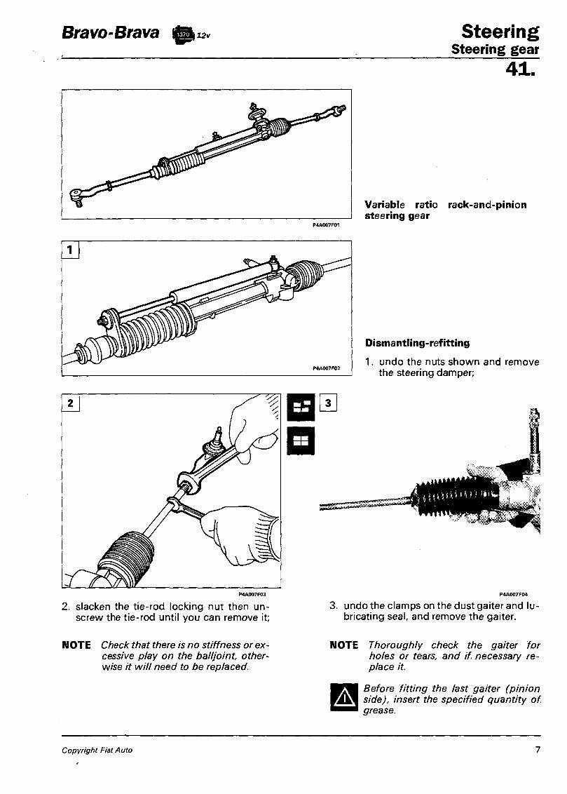
Bravo-Brava ft 12v Steer ing Steering gear
4 1 .
Variable ratio rack-and-pinion steering gear
Dismantling-refitting
1. undo the nuts shown and remove the steering damper;
2. slacken the tie-rod locking nut then unscrew the tie-rod until you can remove it;
3. undo the clamps on the dust gaiter and lubricating seal, and remove the gaiter.
NOTE Check that there is no stiffness or excessive play on the ball joint, otherwise it will need to be replaced.
NOTE Thoroughly check the gaiter for holes or tears, and if necessary replace it.
Before fitting the last gaiter (pinion side), insert the specified quantity of grease.
Copyright Fiat Auto 7

Steering Bravo-Brava Steering gear 41. OPERATION
Its innovative characteristic is that it can reduce the difference between the maximum force applied to the steering wheel when the car is on a bend or carrying out manoeuvres with tight steering angles, and the minimum force applied when the steering wheel is for example in the position for driving on a straight line.
Graph showing the different forces applicable on a constant ratio steering gear and a variable ratio steering gear.
This characteristic is obtained thanks to the particular shape of the rack teeth, which can determine variable ratios between the force applied to the steering wheel and the force transmitted to the wheels, depending on the position assumed by the rack in relation to the pinion. The rack teeth are cut with module and pressure angle varying from the centre towards the ends, so that the pinion engages with teeth of different pitch depending on the steering angle executed. Thus a more direct ratio is obtained when the pinion works on the central part of the rack, and a more geared-down ratio is obtained as the pinion engages nearer the two ends of the rack during turning. This offers more sensitive handling of the car on straight lines and more comfortable handling on bends and during manoeuves.
P4AO08F02
Cross-section of the variable ratio steering gear showing a schematic representation of the rack and pinion teeth.
P4A008F01
-- Constant ratio steering gear Variable ratio steering gear
8 Publication no. 506.670

Bravo-Brava S teer ing Power-assisted steering
4 1 . DESCRIPTION AND OPERATION
The power-assisted steering system comprises: - a feed reservoir located in the engine compartment; - a vane pump driven by the engine, with flow regulating and pressure relief valve; - a set of connecting pipes between pump-distributor valve-actuating cylinder-reservoir; - a hydraulic rack-and-pinion steering gear.
1. Drive shaft 3. Vane impeller 5. Impeller side plate 2. Pump body 4. Seal 6. Regulating valve
Copyright Fiat Auto 9

Steering Power-assisted steering
Bravo-Brava
41 . Power steering distributor valve
The power steering pump is driven by the engine by a belt, and can supply a feed pressure varying from 3.5 bar in the "neutral" position to a maximum of 85 bar in the "full lock" position. The power-assisted steering assembly is similar to a mechanical steering gear, except for the fo l lowing differences:
a. the steering gear contains an actuating cylinder (2) in which a double-effect piston (1) slides, joined to the rack;
b. in the seating of the worm screw, there is a distributor valve (3) w i th its pipes. It is controlled by a torsion device (4), located at the end of the worm screw.
Depending on the torsion transmitted by the steering wheel to the device, the fluid is sent from the pump to the reservoir, or to one of the two chambers A or B of the actuating cylinder. The force generated by the fluid pressure on the lateral surface of the piston causes the piston, and hence the rack, to move.
B
Longitudinal section of power-assisted rack and pinion steering gear
Checking operation
Check the steering wheel's rolling torque with the car stopped and the engine running. The torque should be between 0.6 daN with the engine idling and 0.75 daN with the engine at maximum rpm. If it exceeds these values, check the system pressure w i th the wheels at full lock. To do this, f i t a pressure gauge, wi th a T connector, on the pressurized f lu id delivery pipe to the power steering gear (from the pump) and turn the steering wheel to full lock on one side. When the steering wheel is forced to rotate further, the pressure reading on the pressure gauge should rise to about 85 bar. If this does not happen, check whether there is a fault in the power steering fluid pump or distributor valve.
The above check should be conducted with the engine running at 2000 - 4000 rpm.
NOTE Under no circumstances should the power steering assembly and vane pump be dismantled into their components; instead they should be returned to the manufacturer for overhaul.
Checking fluid level: the fluid level should be checked wi th the engine running, and it should be topped up as necessary.
10 Publication no. 506.670

Bravo-Brava S teer ing Power-assisted steering
4 1 .
A The power-assisted steering system is self-bleeding; it is bled by turning the steering wheel full lock to the right and left with the engine running and the car stopped. This procedure should be carried out whenever the connecting pipes are removed and refitted.
NOTE If the steering becomes hard, this may be due to slipping of the pump pulley belt, or to a low fluid level. If there is a fault in the pump, actuating cylinder or distributor valve, the power steering will function as an ordinary mechanical steering gear.
FRONT WHEEL TOE-IN
On both versions with mechanical steering gear and versions with power-assisted steering, the front wheel toe-in is adjusted by slackening the nut locking the tie-rod and screwing or unscrewing the tie-rod until the specified toe-in value is obtained, without changing the positions of the steering wheel spokes.
Copyright Fiat Auto 11

Steering Power steering gear
Bravo-Brava
4 1 . RACK-AND-PIIMION POWER STEERING GEAR
Removing - refitting
Before removing the power steering gear, drain the fluid from the reservoir.
NOTE The old fluid should not be reused. Top up the level with fresh fluid.
To remove the rack-and-pinion power steering gear, proceed as fol lows:
- remove the bolt securing the shaft to the power steering pinion.
Raise the vehicle, remove the front wheels, then working on both sides:
- undo the nuts securing the right and left tie-rods to the vertical links;
- using tool 1847035000 prise off the t ie-rod end heads from the t w o vertical links;
12 Publication no. 506.670

Bravo-Brava Steer ing Power-assisted steering gear
4 1 .
1. remove the reaction link of the power unit mounting bracket, differential side;
disconnect the Lambda probe wir ing connector; also undo the two nuts on the clamp securing the front exhaust pipe;
3. undo the nuts securing the front exhaust pipe to the catalytic converter and remove the pipe;
Copyright Fiat Auto 13
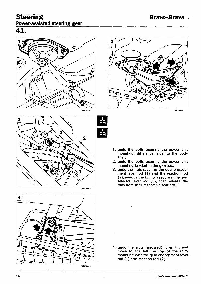
Steer ing Bravo-Brava Power-assisted steering gear 4 1 .
P4A015F01 P4AO15F02
1. undo the bolts securing the power unit mounting, differential side, to the body shell;
2. undo the bolts securing the power unit mounting bracket to the gearbox;
3. undo the nuts securing the gear engagement lever rod (1) and the reaction rod (2) ; remove the split pin securing the gear selector lever rod (3 ) , then release the rods from their respective seatings;
P4A015F03
4. undo the nuts (arrowed), then lift and move to the left the top of the relay mounting wi th the gear engagement lever rod (1) and reaction rod (2) ;
P4A015F04
14 Publication no. 506.670
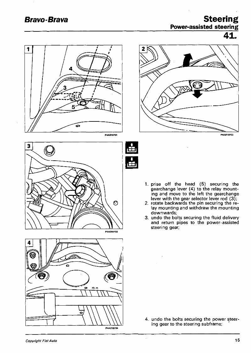
Bravo-Brava Steer ing Power-assisted steering
4 1 .
1. prise off the head (5) securing the gearchange lever (4) to the relay mounting and move to the left the gearchange lever with the gear selector lever rod (3);
2. rotate backwards the pin securing the relay mounting and withdraw the mounting downwards;
3. undo the bolts securing the fluid delivery and return pipes to the power-assisted steering gear;
4. undo the bolts securing the power steering gear to the steering subframe;
Copyright Fiat Auto 15

Steering Power-assisted steering gear
Btavo-Brava
41 .
- withdraw the power steering gear from underneath the vehicle.
NOTE To refit the power steering gear, reverse the procedure for removal.
A Check the front wheel toe-in whenever the steering gear is removed-refitted.
Dismantling-refitting
1. slacken the nut locking the tie-rod then unscrew the tie-rod until you can remove it;
NOTE Check that there is no stiffness or excessive play on the balljoints.
Power assisted rack-and-pinion steering gear
mm <1
2. undo the clamps on the dust gaiter and lubricating seal, and remove the gaiter.
NOTE Thoroughly check the gaiter for holes or tears, and if necessary replace it.
A Before fitting the last gaiter (pinion side), insert the specified quantity of grease.
16 Publication no. 506.670

Bravo-Brava ft 12v Steer ing Power steering pump
4 1 .
Removing-refitting
To remove the power steering pump, proceed as fol lows: 1. empty the fluid reservoir using a syringe;
NOTE The old fluid should not be reused. Top up the level with fresh fluid.
2. undo the clamps and remove the air intake pipe;
3. undo the bolts indicated and remove the belt guard;
4. disconnect the f luid inlet and outlet pipes from the power steering pump.
Copyright Fiat Auto 17

Steer ing Bravo-Brava Power steering pump 41 .
Place the vehicle on ramps, remove the front wheel, then: - undo the bolts, release the button and re
move the right wheelarch cover; P4A019F01
- slacken the pump pulley bolts;
- slacken the belt tensioner and remove the belt;
P4A019F03
18 Publication no. 506.670

Bravo-Brava ft 12v Steer ing Power steering pump
4 1 .
undo the bolts and remove the pulley;
undo the bolts securing the pump to the bracket and remove the pump.
NOTE To refit the power steering pump, reverse the procedure for removal.
Copyright Fiat Auto 19
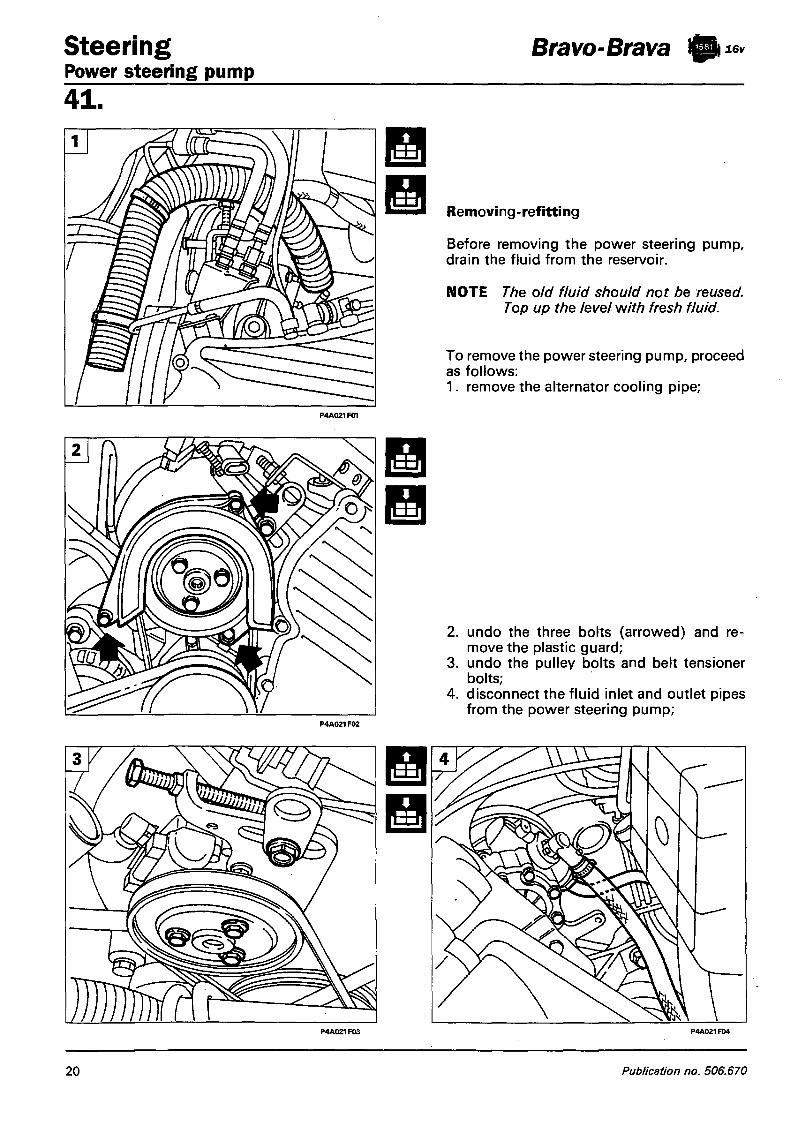
Steering Power steering pump
Bravo-Brava ft 16v
41 .
Removing-refitting
Before removing the power steering pump, drain the fluid from the reservoir.
NOTE The old fluid should not be reused. Top up the level with fresh fluid.
To remove the power steering pump, proceed as follows: 1. remove the alternator cooling pipe;
2. undo the three bolts (arrowed) and remove the plastic guard;
3. undo the pulley bolts and belt tensioner bolts;
4. disconnect the fluid inlet and outlet pipes from the power steering pump;
20 Publication no. 506.670

Bravo-Brava fti* S teer ing Power steering pump
4 1 .
1. undo the bolts and remove the pulley and belt;
P4A022F01
verse the procedure for removal.
Copyright Fiat Auto 21

Steer ing Power steering pump
Bravo-Brava ft 16v
4 1 .
Removing-refitting
Before removing the power steering pump, drain the fluid from the reservoir.
NOTE The old fluid should not be reused. Top up the level with fresh fluid.
To remove the power steering pump, proceed as follows: 1. undo the pump pulley bolts;
Place the vehicle on ramps, remove the front right wheel, then: 2. undo the bolts, release the button and re
move the right wheelarch cover; 3. slacken the belt tensioner and remove the
belt; 4. undo the bolts and remove the pulley.
22 Publication no. 506.670

Bravo-Brava ft 16v Steer ing Power steering pump
4 1 .
Working from the engine compartment, carry out the following operations: 1. undo the two bolts securing the link to the
engine and the bracket, and remove the link;
2. undo the bolts securing the bracket and link to the bodywork and remove the bracket;
3. disconnect the wiring connector and earth cable;
4. disconnect the fluid inlet and outlet pipes from the power steering pump.
Copyright Fiat Auto 23

Steer ing Power steering pump
Bravo-Brava ft 16v
4 1 .
Raise the vehicle, then: - from the rear, undo the bolts securing the
inlet manifold reaction bracket and remove the bracket;
- undo the bolts securing the alternator mounting bracket and remove the bracket;
- undo the bolts securing the power steering pump and remove it.
NOTE To refit the power steering pump, reverse the procedure for removal.
24 Publication no. 506.670

Bravo-Brava ft 20v Steer ing Power steering pump
4 1 .
Removi ng - ref itti ng
Before removing the power steering pump, drain the fluid from the reservoir.
NOTE The old fluid should not be reused. Top up the level with fresh fluid.
To remove the power steering pump, proceed as fol lows: - disconnect the f luid inlet pipe from the
power steering pump;
after slackening and removing the belts in accordance with the procedure described in Sec. 10, undo the bolt and remove the pulley from the power steering pump;
- unscrew the delivery pipe connector (arrowed), then withdraw the pump wi th the hose.
NOTE To refit the power steering pump, reverse the procedure for removal, then refit and tension the belts as described in Sec. 10.
Copyright Fiat Auto 25
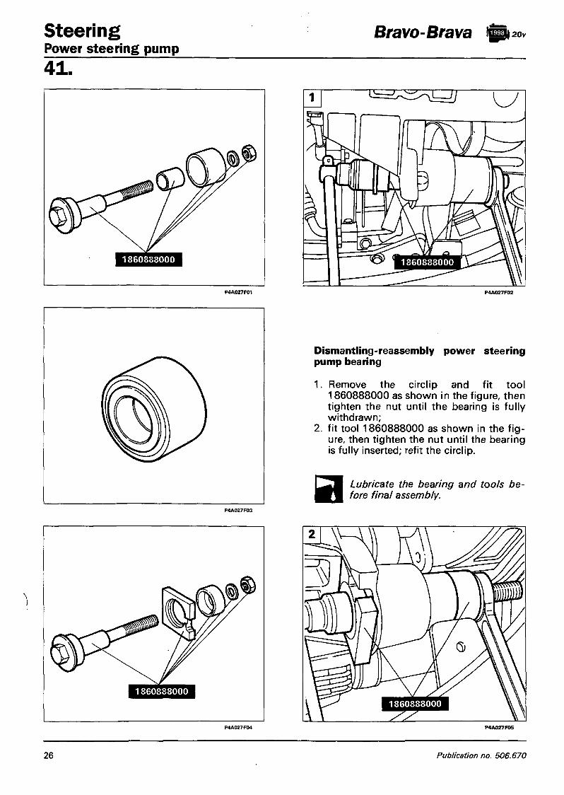
Steer ing Power steering pump 4 1 .
1 8 6 0 8 8 8 0 0 0
Bravo-Brava igp 20v
P4A027F02
Dismantling-reassembly power steering pump bearing
1. Remove the circlip and fit tool 1860888000 as shown in the figure, then tighten the nut until the bearing is fully withdrawn;
2. fit tool 1860888000 as shown in the figure, then tighten the nut until the bearing is fully inserted; refit the circlip.
Lubricate the bearing and tools be-V I fore final assembly.
P4A027F05
26 Publication no. 506.670

Bravo-Brava fti< Steer ing Power steering pump
4 1 .
Removing-refitting
To remove the power steering pump, proceed as follows: 1. drain the fluid reservoir using a syringe;
NOTE The old fluid should not be reused. Top up the level with fresh fluid.
2. undo the bolts (arrowed) and remove the belt guard; also undo the pulley nut;
3. disconnect the fluid inlet and outlet pipes from the power steering pump;
4. undo the bolts (1) and (2), screw up the belt tensioner (3) to reduce the belt tension, then remove the belt;
Copyright Fiat Auto 27

Steering Power steering pump
Bravo-Brava ® i o
41 .
1. remove the bolts (1) and (2), then remove the pump body complete with pulley and mounting brackets;
2. undo the nut and remove the pulley;
Be careful with the washer during both removal and refitting of the pulley.
3. undo the bolts indicated and remove the rear bracket; also undo the nut (1) on the front bracket;
4. undo the remaining bolts and remove the front bracket.
NOTE To refit the power steering pump, reverse the procedure for removal.
28 Publication no. 506.670

Bravo-Brava ft™ Steer ing Power steering pump
4 1 .
The documentation relating to this engine was not yet available at the time of going to print.
The procedure for removing and refitting the power steering pump wi l l be published in a subsequent update.
Copyright Fiat Auto 29

Steering Power steering pump 41 . 1910 TD ENGINE
The documentation relating to this engine was not yet available at the time of going to print.
The procedure for removing and refitting the power steering pump will be published in a subsequent update.
Bravo-Brava ft™
30 Publication no. 506.670

Bravo-Brava Suspension and whee ls Contents
4 4 . ' . page
FRONT SUSPENSION
- Diagram of front suspension assembly 1 - Wishbone and steering subframe 2 - Spring-damper assembly 6
- - Vertical linLand wheel hub 8 - Components of the front suspension
supplied as spare parts 14
REAR SUSPENSION
- Diagram of rear suspension assembly 16 - Removing-refitting 17 - Dismantling-refitting 22 - Stub axle-Rear wheel hub 24 - Components of the rear suspension sup- .
plied as spare parts 28
WHEEL GEOMETRY
- Front wheel geometry 29 - Rear wheel geometry . 30
Copyright Fiat Auto

Bravo-Brava
DIAGRAM OF FRONT SUSPENSION ASSEMBLY
Suspension and whee ls Front suspension
4 4
Copyright Fiat Auto 1

Suspension and wheels Front suspension
Bravo-Brava
44.
P4A002G02
WISHBONE AND STEERING SUBFRAME
Removal
To remove the wishbone and the steering subframe, place the car on ramps, remove the front wheels and the front section of the exhaust pipe, then carry out the following operations: 1. undo the bolt securing the wish
bone balljoint to the vertical link;
2. undo the two nuts securing the anti-roll bar link and remove the link;
2 Publication no. 506.670

Bravo-Brava Suspension and w h e e l s Front suspension
44^
P4A003G02
Copyright Fiat Auto 3

Sospensioni e ruote Sospensione anteriore
Bravo-Brava
44 .
1 . rimuovere il riparo anticalore; 2. svitare le viti di fissaggio della scatola ser-
vosterzo alia traversa anteriore; 3. posizionare un sollevatore idraulico a co-
lonna sotto la traversa, quindi svitare le viti di fissaggio della traversa alia scocca (frecce); abbassare lentamente il sollevatore e rimuovere la traversa anteriore.
Riattacco
NOTA Per il riattacco della traversa anteriore e del braccio oscillante eseguire in senso inverso le ope-razioni previste per lo stacco.
Effettuare la convergenza ruote anterior '/ ogni qualvolta si esegua lo stacco-riattacco della traversa anteriore o di un braccio oscillante.
4 Stampato n° 506.668

Bravo-Brava Suspension and w h e e l s Front suspension
4 4 . Dismantling-refitting anti-roll bar on steering subf rame
Checking anti-roll bar
Neither the rubber buffers nor the bar should show signs of damage, otherwise the buffers and the bar must be replaced.
< I > Checking steering subframe
Check that the steering sub-frame is not cracked or deformed such that its efficiency is impaired.
P4A005G03
Refitting steering subframe to body shell
The subframe should be secured temporarily, then centred on the bodywork using two studs of a diameter of about 1 2 mm, then it should be secured finally.
BB&B A
<•> Components of the front suspension supplied as spare parts
1. Anti-roll bar 2 . Bracket securing anti-roll bar to steer
ing subframe 3. Steering subframe 4. Link connecting anti-roll bar to wish
bone 5. Wishbone 6. Washer for rubber buffer 7. Rubber buffer
When refitting the anti-roll bar, fit the washers, shown in the insert, with the face (A) facing the rubber buffer (2). Incorrect assembly could impair the life of the rubber buffer (2).
Copyright Fiat Auto 5

Suspension and wheels Front suspension
Bravo-Brava
44 .
SPRING-DAMPER ASSEMBLY
Removing - ref itti ng
To remove the spring-damper assembly, proceed as follows:
1. undo the bolts securing the damper top plate to the bodywork;
2. undo the bolts securing the damper to the vertical link and remove the coil spring and damper assembly.
Assembly with offset coil spring
Dismantling-refitting
Detach the coil spring from the damper as follows:
- fit the spring-damper assembly on the pneumatic tool 1874555000 and operate the lever (1) so as to lock the assembly;
6 Publication no. 506.670

Bravo-Brava Suspension and whee ls Front suspension
4 4 .
3.
adjust the position of the hooks (2), moving them close to the spring, then place the tool under pressure until the spring begins to compress; prise off the dust excluder using a screwdriver; undo the nut securing the top plate to the damper stem and remove the plate, then withdraw the spacer, spring and end-of-travel stop.
1 0 d a N m
NOTE The coil springs are divided into two categories, identifiable by means of a strip of paint on the central coil. Springs of the same category must be fitted.
Refit the components in reverse order, tighten the damper stem nut to the correct torque then refit the dust excluder.
Copyright Fiat Auto 1

Suspension and wheels Front suspension
Bravo-Brava
44. VERTICAL LINK AND WHEEL HUB
Removal
To remove the front vertical link and wheel hub, proceed as follows:
- undo the nut securing the front wheel hub to the stub axle;
P4A008G02
- undo the bolts securing the brake caliper assembly to the vertical link;
P4A008G03
withdraw the brake caliper complete with mounting bracket and secure it in the wheelarch without disconnecting the brake pipe;
8 Publication no. 506.670

Bravo-Brava Suspension and w h e e l s Front suspension
P4A009G05
Copyright Fiat Auto 9

Suspension and wheels Bravo-Brava Front suspension 44.
\
- undo the bolts securing the spring-damper assembly to the vertical link;
P4A010G01
1 0
P4A010Q03
Front and rear views of vertical link complete with hub
P4A010G04
Publication no. 506.670

Bravo-Brava Suspension and whee ls Front suspension
4 4 .
Dismantling
To dismantle the vertical link and wheel hub, proceed as follows:
- dismantle the hub from the vertical link using a press;
using a chisel, separate the bearing inner ring from the hub, then withdraw the bearing using the tools shown;
Longitudinal section of front wheel hub assembly and disc brake
P4A011G04
1 . Wheel hub 2. Brake disc 3. Vertical link 4. Ball bearing
Constant velocity joint
Copyright Fiat Auto 11
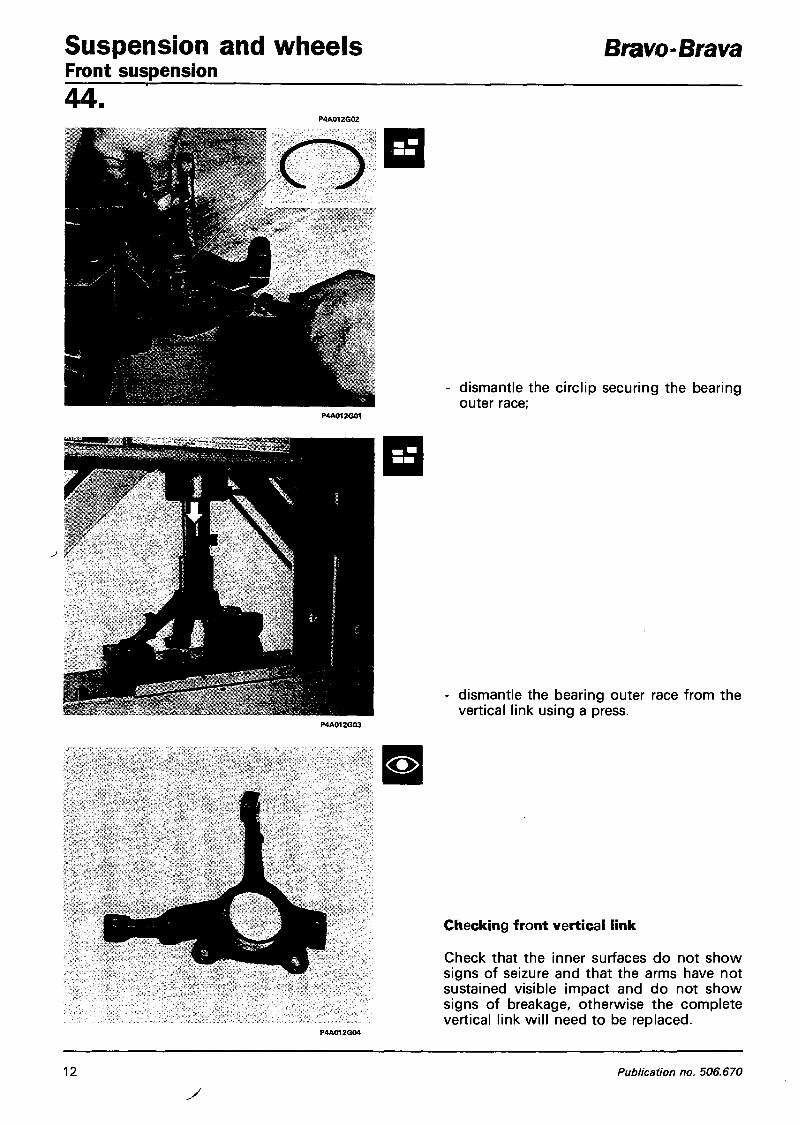
Suspension and wheels Front suspension 44 .
Bravo-Brava
dismantle the circlip securing the bearing outer race;
dismantle the bearing outer race from the vertical link using a press.
<•>
Checking front vertical link
Check that the inner surfaces do not show signs of seizure and that the arms have not sustained visible impact and do not show signs of breakage, otherwise the complete vertical link wil l need to be replaced.
1 2 Publication no. 506.670

Bravo-Brava Suspension and w h e e l s Front suspension
4 4 .
Refitting
The bearing can be refitted on the vert ical link either using a press, or using the handle 1870007000. Then fit the bearing circlip.
Fit the hub in the bearing on the vertical link using a press, supporting the bearing inner race wi th a cylinder (1) of suitable diameter.
Copyright Fiat Auto 13

Suspension and wheels Front suspension
Bravo-Brava
44 .
<i> anPa
A
COMPONENTS OF THE FRONT SUSPENSION SUPPLIED AS SPARE PARTS
Components of the damper top mounting
Check that the components have no faults that might impair their efficiency.
Damper
If faults attributable to the damper are found, the entire damper assembly should be replaced.
Coil spring
Make sure that it has no cracks or deformations that might impair its efficiency.
NOTE The coil springs are divided by means of a yellow or green paint strip on the central coil. Coils of the same category should be fitted.
Wishbone
Check that the wishbone is not deformed, that the balljoint head does not have excessive play, that the dust excluder is not damaged and that the rubber bushes are not worn, otherwise the complete wishbone wi l l need to be replaced.
1. Damper 2. Coil spring 3. Damper top plate 4. Spacer 5. Rubber buffer 6. Tube and end-of-travel stop 7. Vertical link
8. Wishbone 9. Constant velocity joint + stub axle
10. Bearing circlip 1 1 . Ball bearing 12. Wheel hub 13. Wheel hub nut
14 Publication no. 506.670

Bravo-Brava Suspension and w h e e l s Front suspension
4 4 .
24 daIMm
28 da [Mm
Fitting hub nut and tightening it to correct torque
The nuts securing the constant velocity joints to the hubs must always be replaced.
Also check: Front wheel geometry
Staking hub nut
To stake the nut, proceed as described below:
- always use a new nut; - thoroughly clean the threaded end of the
half-shaft using a metal brush, and then with a compressed air jet;
- clean the thread on the new nut and the threaded end of the half-shaft using paper towel moistened with ethyl alcohol or heptane;
- apply Loctite 270 (or an equivalent product) on the entire threaded part of the half¬-shaft end;
- tighten the new nut, securing it to the specified torque within 5 minutes of applying the adhesive;
- stake the nut collar using the chisel shown in figure 1 (the chisel should be made on site in accordance wi th the dimensions shown on the drawing, and taken from article USAG 362 or similar).
The collar should be cut on the notch of the hub on the side opposite that of tightening the nut, so that the safety lug opposes accidental uncrewing (see figure 2) .
Copyright Fiat Auto 15

Suspension and wheels Rear suspension
Bravo-Brava
44 . DIAGRAM OF REAR SUSPENSION ASSEMBLY
1. Anti-roll bar 2. Trailing arm 3. Spring
4. Torsion bar 5. Damper
16 Publication no. 506.670

Bravo-Brava Suspension and w h e e l s Rear suspension
4 4 . REMOVING-REFITTING
NOTE To remove the rear suspension, first remove the fuel tank and the rear section of the exhaust pipe.
Fuel tank
To remove the fuel tank, proceed as fol lows:
1. remove the luggage compartment shelf trim and remove the plastic cover;
2. disconnect the two wiring connectors; 3. undo the nut and disconnect the vent pipe
(1), then release the retaining lugs and disconnect the fuel delivery and return pipes (2);
Copyright Fiat Auto 17

Suspension and wheels Bravo-Brava Rear suspension 44]
1 8 Publication no. 506.670

Bravo-Brava Suspension and w h e e l s Rear suspension
4 4 .
P4A019G04
1. place a column jack under the tank, undo the bolts and remove the attachment buttons shown, then gently lower the fuel tank;
2. open the clip and disconnect the petrol vapour pipe;
3. fully lower the jack and remove the tank.
Copyright Fiat Auto 19

Suspension and wheels Bravo-Brava Rear suspension 44.
P4A020G05 P4A020G04
20 Publication no. 506.670

Bravo-Brava Suspension and w h e e l s Rear suspension
4 4 .
P4A021G01 P4A021G02
Suspension assembly
To remove the rear suspension assembly, proceed as fol lows:
1. disconnect the brake pipe connections; 2. slacken the handbrake cable assembly and
disconnect the cables; 3. unscrew and move aside the A.B.S. sensor;
4. place a hydraulic jack under the suspension crossframe and undo the bolts securing the suspension to the body; lower the hydraulic jack and remove the rear suspension assembly.
P4AO21G04
Copyright Fiat Auto 21

Suspension and wheels Rear suspension
Bravo-Brava
44. DISMANTLING-REFITTING
Rear suspension on overhaul stand
4 Dismantling anti-roll bar from attachments on trailing arm
Anti-roll bar
Check that the anti-roll bar is not damaged or deformed, otherwise it will have to be replaced. Check that the rubber grommets are not damaged.
NOTE Whenever the brake pipes are removed, check with compressed air that they are not blocked. They should be replaced if they have dents, constrictions, cracks or worn connections.
P4A022G04
Dismantling brake pipes from attachments on rear torsion bar
22 Publication no. 506.670

Bravo-Brava Suspension and w h e e l s Rear suspension
4 4 .
Dismantling damper from anchorage on trailing arm
To remove the damper, compress the rear suspension with a hydraulic jack.
Dismantling damper from anchorage on rear torsion beam
Dismantling - refitting brake drum
Copyright Fiat Auto 2 3

Suspension and wheels Rear suspension
Bravo-Brava
44.
Dismantling dust cap from wheel hub
Refitting dust cap on wheel hub
NOTE Before assembly, smear TUTELA MR3 grease around the edge of the cap.
STUB AXLE - REAR WHEEL HUB
Dismantling-reassembly nut securing stub axle and wheel hub
Whenever the hub nut is removed, it should be replaced with a new one.
NOTE The hub nut should be tightened to the correct torque wiht the rear torsion beam fitted to the car.
Checking stub axle
The stub axle must not be cracked, deformed or worn, otherwise it has to be replaced.
Checking hub
If the wheel bearing (arrowed) is replaced because of noisiness or excessive play, the complete hub must be replaced.
24 Publication no. 506.670

Bravo-Brava Suspension and w h e e l s Rear suspension
4 4 .
Dismantling trailing arm from rear torsion beam
<i>
Checking trailing arm
Check that the trailing arm is not cracked, deformed or worn (on the surface on the wheel side), otherwise it will have to be replaced. If the bearings and spacer (arrowed) are replaced because of noisiness or excessive play, the trailing arm must be replaced.
Checking rear torsion beam
Check that the rear beam is not cracked or deformed, or misaligned between the two side arms, otherwise it will have to be replaced.
Copyright Fiat Auto 25
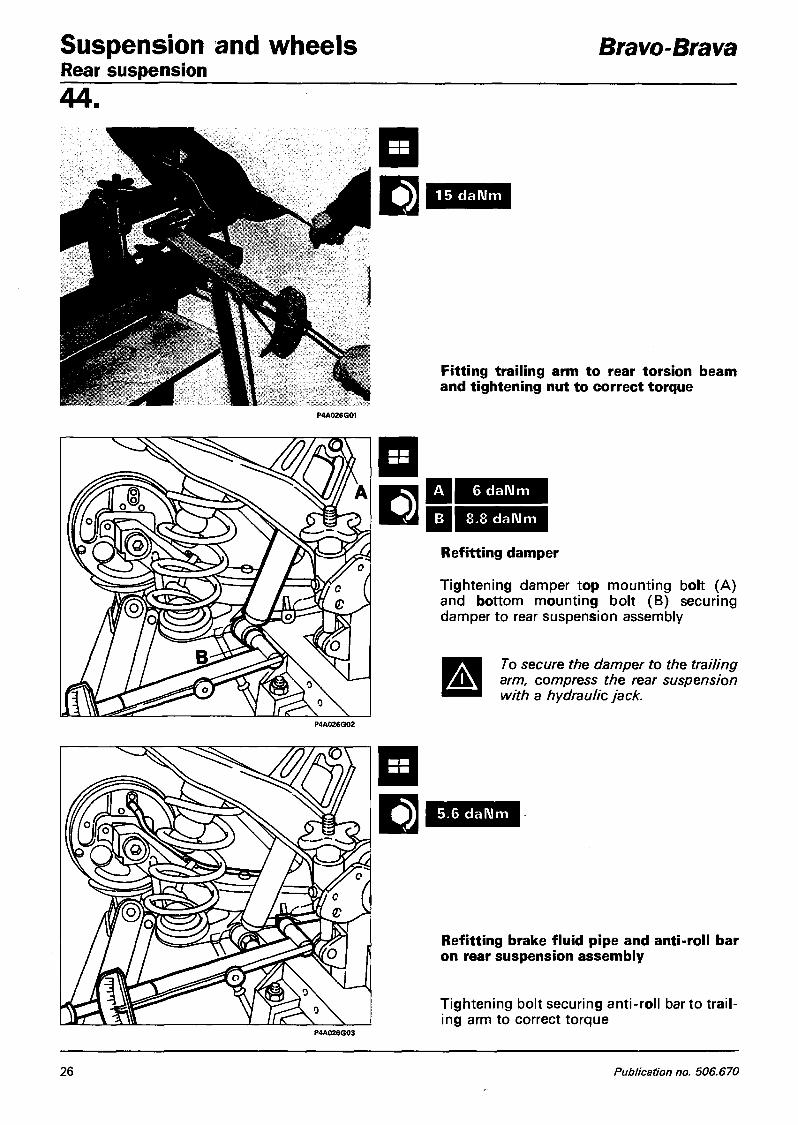
Suspension and wheels Rear suspension
Bravo-Brava
44.
15 daNm
Fitting trailing arm to rear torsion beam and tightening nut to correct torque
A 6 daNm
B 8.8 daNm
Refitting damper
Tightening damper top mounting bolt (A) and bottom mounting bolt (B) securing damper to rear suspension assembly
A To secure the damper to the trailing arm, compress the rear suspension with a hydraulic jack.
5.6 daNm
Refitting brake fluid pipe and anti-roll bar on rear suspension assembly
Tightening bolt securing anti-roll bar to trail ing arm to correct torque
26 Publication no. 506.670

Bravo-Brava Suspension and w h e e l s Rear suspension
4 4 .
1 0 . 8 daNm
Refitting rear suspension
Tightening bodywork attachment bolts to correct torque
28 daNm
P4A027G02
Also:
Bleed the brakes
Check the rear wheel geometry
Tightening nut securing stub axle and wheel hub to correct torque
Copyright Fiat Auto 27

Suspension and whee ls Bravo-Brava Rear suspension 44. COMPONENTS OF THE REAR SUSPENSION SUPPLIED AS SPARE PARTS 1. Rear torsion beam - 2. Rubber buffers - 3. Damper top mounting bolt - 4. Coil spring - 5. Damper -6. Bottom nut and bolt securing damper to trailing arm - 7. Cast iron trailing arm - 8. Anti-roll bar - 9. Nut and bolt securing trailing arm to rear torsion beam - 10. Stub axle -11 . Wheel hub - 12. Nut securing stub axle and wheel hub -13. Hub dust cap
<§>
an^a
Wheel hub If the wheel bearing has to be replaced because of noisiness or excessive play, the hub complete with bearing will have to be replaced. \
Stub axle The stub axle must not be cracked, deformed or worn, otherwise it will have to be replaced.
Damper If faults attributable to the damper are found, the entire damper assembly should always be replaced.
Coil spring 13 Make sure that it is not cracked or deformed such that its efficiency is impaired. NOTE The coil springs are divided into two categories identified by a yellow or green strip of paint on
the central coil. Springs of the same category must be fitted.
28 Publication no. 506.670

Bravo-Brava Suspension and whee ls Wheel geometry
4 4 . FRONT WHEEL GEOMETRY The wheel geometry must be checked after the components that affect it have been subjected to the following checks: - tyre pressures; - the eccentricity and out-of-true of the wheel rims must not exceed 3 mm; - wheel bearing endfloat; - clearance between vertical link and wishbone balljoint pin; - tie-rod end play.
P4A029G02 P4A029G03
TOE-IN CAMBER (non adjustable) CASTER (non adjustable)
See data in Sec. 00
P4A029G04
If, when checking the toe-in, the values measured are not as specified, slacken the steering tie-rod nuts and adjust the steering tie-rods.
If the wheel camber angle is not as specified, check the vehicle body shell.
Closely follow the instructions below whenever you adjust the front wheel toe-in: - undo the clips securing the gaiters on the tie-rods: - check that the gaiter turns freely on the tie-rod; if necessary remove the gaiter and lubricate
wth MOLYGUARD SYL 133 silicone grease or a similar product; - tighten the clip after adjusting the toe-in and only after checking that the gaiter is in the cor
rect position.
Copyright Fiat Auto 29

Suspension and wheels Bravo-Brava Wheel geometry 44 . REAR WHEEL GEOMETRY
The wheel geometry must be checked after the fol lowing checks have been carried out: - tyre pressures; - the eccentricity and out-of-true of the wheel rims must not exceed 3 mm; - wheel bearing endfloat.
If the rear wheel angles are not as specified, they cannot be adjusted as the rear suspension comprises a rigid torsion beam.
30 Publication no. 506.670