Embed Size (px)
Citation preview

- Floor mounted for concealed or exposed applications- Standard and high capacity coils- Optionalcolors,valvepackages,controlsandunitconfigurations- Nominal CFM range of 200 to 1200 CFM
• Easy to install
• Easy to Service
• Durable construction
• Designflexibility
Vertical F*C SeriesFAN COIL TECHNICAL CATALOG
FHC
FVC
FXC

Vertical F*C SeriesFAN COIL TECHNICAL CATALOG
2
International Environmental Corporation (IEC) works continually toimproveitsproducts.Asaresult,thedesignandspecificationsof each product may be changed without notice and may not be as described herein. Please contact IEC for information regarding currentdesignandproductspecifications.Statementsandotherinformation contained herein are not express warranties and do not form the basis of any bargain between the parties but are merely IEC’s opinion or commendation of its products. Manufacturer’s standard limited warranty applies.

Vertical F*C SeriesFAN COIL TECHNICAL CATALOG
3
Table of Contents
4 Portfolio
5 Features and Benefits
6 Unit Model Key
7-8 Ratings and Listings
9-12 PSC Fan Curves – FXC, FVC
13-16 PSC Fan Curves – FHC
17-20 ECM Fan Curves – FXC, FVC
21-24 ECM Fan Curves – FHC
25 Motor Performance Data
26 Sound Power Data
27 Electric Heating
28-36 Submittal Data
37-45 Standard Features, Options and Accessories

Vertical F*C SeriesFAN COIL TECHNICAL CATALOG
4
Vertical Hideaway (FHC) 200 CFM to 1200 CFMThe Vertical Hideaway (FHC) fan coil unit is designed for concealed applications. The slender design of the FHC makes this unit ideal for perimeter heating and cooling applicationsinpublicbuildings,offices,hospitalsandhotels. The coil section of the FHC is lined with insulation to provide positive protection against sweating and maximum dampening of air noise. Standard FHC units areprovidedwithagalvanizedfinish.
Vertical Cabinet (FXC) 200 CFM to 1200 CFMThe slender design of the Vertical Cabinet (FXC) fan coil unit makes this unit ideal for perimeter heating and coolingapplicationsinpublicbuildings,offices,hospitalsand hotels. The FXC cabinet is fabricated of heavy gauge steel. The top panel provides structural rigidity essential for an exposed unit. FXC units have a removable, one-piece front panel for easy access to all internal components. Standard FXC units are provided with a durablepowder-coatedpaintfinish.
Vertical Sloped Top Cabinet (FVC) 200 CFM to 1200 CFMThe Vertical Sloped Top Cabinet (FVC) fan coil unit is designedforapplicationsinpublicbuildings,officesandhospitals where it is necessary to prevent books and other items from being placed over the discharge grilles on the top panel. The FVC cabinet is fabricated of heavy gauge steel. The 25-degree, sloped, top panel provides structural rigidity essential for an exposed unit. FVC units have a removable, one-piece front panel for easy access to all internal components. Standard FVC units are providedwithadurablepowder-coatedpaintfinish.
Portfolio

Vertical F*C SeriesFAN COIL TECHNICAL CATALOG
5
FeaturesandBenefitsApplication Fit
• Several cabinet types allow for a multitude of room layouts.
- Theverticalflattopcabinetunits(FXC)areideal for perimeter air conditioning, ideally placed under a window to mitigate the effects of heat losses or gains through the glazing.
- The vertical sloped top cabinet units (FVC) discourages the placement of objects on the supplygrille,blockingairflow,whichcouldpotentially result in performance issues.
- The vertical hideaway version of the above units (FHC) is tailored to recess in a wall or continuous cabinetry to meet architectural needs.
Design Flexibility• Standard and high capacity hydronic coils are
available to match the space heating and cooling loads.
• OptionalfinishesandcolorsareavailableonFVC/FXC models, allowing the unit to blend in with any decor.
• Optional back panel provides an aesthetic cover for units that are visible from the building exterior, which are not completely covered by a wall or other architecture.
• Special cabinetry can be designed for jobs where unique cabinet dimensions are required, most often found on renovation projects.
• Optionalairflowconfiguration(frontsupply)to enhance performance, given certain design limitations.
• Wide variety of valve package options to meetdesiredcontrolsspecifications;factorypreassembledandshippedlooseforfieldinstallation.
• Variety of insulation materials to address IAQ concerns.
• Optionalcondensatefloatswitchtomeetlatestbuilding code requirements.
• Product integrated into IEC’s computer rating program for quick performance calculations to aid in unit selection & quoting.
Ease of Installation• Preassembled valve packages are available, to reducefieldpipingperformedatthejobsite.
• Optional unit mounted controls, service switches and fusing minimize on-site electrical work.
• Units are tagged at the factory for ease of identificationonthejobsite.
• Opposite end coil connections are an optional feature intended to minimize the piping work on renovation jobs.
• Custom cabinetry facilitates installations by:- Deeper units allow the piping to run along the
wall minimizing piping work and providing an insulated plenum that eliminates outside air transitions on renovation jobs.
- Wider units allow for same end piping and electricalconnectionstominimizefloorpenetrationsandeliminatetheneedforfillercabinetry.
Ease of Service• All commonly serviced components are accessible
by simply removing the front panel.• Filters can be easily replaced without tools or
removing the front panels of exposed units.• Slide-out blower assembly for maintenance
convenience.• Positively sloped drain pan easily removes
condensate, and inhibits the occurrence of standing water.
Quality and Safety• Rigorous multi-point inspection at the factory for
trouble-free start-up.• ETL listed for safety compliance to UL 1995, US &
Canada.• AHRIcertifiedforperformancetoAHRI440.• All hydronic coils are pressure tested to 300 psig.

Vertical F*C SeriesFAN COIL TECHNICAL CATALOG
6
Unit Model Key
Arrangement57
ELECTRIC HEAT
Code Items
Coil Connection
CONTROLSHAND/ ARRANGEMENT
2-pipe Cooling and Heatingor 4-pipe Cooling
4-pipe Heating
01 02
UNIT VINTAGE SIZE
Code
COILS
04F H C
FHC • Vertical HideawayFXC • Vertical CabinetFVC • Vertical Sloped Top Cabinet
030 4
02 • 200 CFM03 • 300 CFM04 • 400 CFM05 • 500 CFM06 • 600 CFM08 • 800 CFM10 • 1000 CFM12 • 1200 CFM
A Y Y04a
C B Y Y
MOTOR
05C 2
06R 5
07C P N
Voltage C • 115-1-60D • 208-1-60E • 230-1-60F • 277-1-60V • 220-1-50*U • 240-1-50*
Hand**
R • RightL • Left
Voltage***C • 120VD • 208VE • 240VF • 277VV • 220V (50 Hz)*U • 240V, (50 Hz)*
D • 2-RowA • 3-RowB • 4-Row
Y • None6 • 1-Row7 • 2-Row
Y • NoneS • Same EndO • Opposite End
kW* Y • None GY • 4.00BY • 1.00 HY • 5.00CY • 1.50 JY • 6.00DY • 2.00FY • 3.00
StagesY • Single Stage Only
VoltageB • 24VC • 120VD • 208VE • 240VF • 277VV • 220V (50 Hz)*U • 240V (50 Hz)*
ThermostatA • Basic Electronic Wall Series, 155, VerticalB • Basic Electronic Wall Series, 155, HorizontalC • Basic Series, 156, Unit MountedP • Basic 24V Digital, 7-Day ProgrammableN • Basic 24V Digital, Non-ProgrammableF • Premium 24V Digital, 7-Day Programmable/ BACnet with Proportional Fan/ Valves OptionG • Premium 24V Digital BACnet with Proportional Fan/ Valves OptionW • Venture 24V Wi-Fi Programmable
System
Manual Fan OperationA1 • Standard Unit Mount (Switch Only)A2 • Standard Wall Mount (Switch Only)
Phase1 • 1-Phase3 • 3-Phase
* Consult factory for 50 Hz applications.** Standing in front of the unit, hand is
determined by looking into the air supplyand assigning the hand to match thelocation of the cooling coil connections.
*** Note that kWs range from 1.0 to 6.0depending on voltage and unit size.
Type 2 • Permanent Split CapacitorA • ECM, 3-Spd Relay Brd (L/M/H)B • ECM, Proportional (0-10VDC)C • ECM, 4-Spd Board, Solid State w/PWM
FHC, FXC FHC
775 5

Vertical F*C SeriesFAN COIL TECHNICAL CATALOG
7
Model Size Coil Rows
Air Flow
Rating (SCFM)
Water Pressure Drop (ft. water)
Total Cap.
(Btuh)
Sensible Cap.
(Btuh)
Power Input
(Watts)
FHC
02 2 200 7.2 5,100 3,900 65
02 3 200 17.5 6,900 4,700 65
02 4 200 9.4 7,900 5,200 6503 2 300 4.4 5,800 4,400 80
03 3 300 8.5 8,100 5,900 8003 4 250 15.0 9,200 6,500 80
04 2 400 12.9 9,500 7,600 150
04 3 400 20.0 11,400 8,400 135
04 4 400 6.3 12,700 9,100 135
05 2 500 4.1 11,700 9,700 225
05 3 500 9.1 15,400 10,500 180
05 4 500 10.0 17,500 11,800 230
06 2 600 3.5 13,000 10,200 190
06 3 600 14.1 18,700 13,400 190
06 4 600 11.9 20,600 14,200 190
08 2 680 5.0 14,000 10,700 200
08 3 680 17.5 20,800 14,400 200
08 4 680 13.6 21,700 14,300 200
10 2 1,000 12.5 25,200 18,700 290
10 3 1,000 21.3 31,700 21,100 275
10 4 1,000 18.3 30,700 19,900 275
12 2 1,200 6.8 25,300 20,200 360
12 3 1,200 17.2 34,100 23,900 355
12 4 1,200 18.3 38,900 25,600 350
C-ETL-US ListingIEC’s Vertical F*C Series units are listed by ETL. The C-ETL-US listingsignifiesthatIEC’sfancoil units have been examined by ETL and are in compliance with both the U.S. and Canadian applicable standards.
Rating and ListingsAHRI CertificationIEC’s Vertical F*C Series unitsarecertifiedincompliance with Air-Conditioning, Heating, and Refrigeration Institute (AHRI) industry standard AHRI-440 for room fan coil units. Approved standard ratings are tabulated below. 3061627
HEATING AND COOLING EQUIPMENT
PSC Motor Standard Ratings
Model Size Coil Rows
Air Flow
Rating (SCFM)
Water Pressure Drop (ft. water)
Total Cap.
(Btuh)
Sensible Cap.
(Btuh)
Power Input
(Watts)
FXC, FVC
02 2 200 7.2 5,100 3,900 65
02 3 200 17.5 6,900 4,700 65
02 4 200 15.0 8,000 5,200 65
03 2 280 6.0 5,800 4,400 80
03 3 300 8.5 8,100 5,900 80
03 4 270 15.0 9,500 6,400 80
04 2 400 12.9 9,300 7,600 150
04 3 400 15.5 11,600 8,800 135
04 4 400 6.3 12,700 9,100 135
05 2 500 4.1 11,700 9,700 225
05 3 500 9.1 15,400 10,500 180
05 4 500 5.5 17,500 11,800 230
06 2 600 6.0 13,000 10,200 200
06 3 600 14.1 18,700 13,400 190
06 4 600 11.9 20,600 14,200 190
08 2 680 5.0 14,000 10,700 200
08 3 680 17.5 20,800 14,400 200
08 4 680 13.6 21,700 14,300 200
10 2 1,000 12.5 25,200 18,700 290
10 3 1,000 21.3 31,700 21,100 275
10 4 1,000 18.3 30,700 19,900 275
12 2 1,200 6.8 25,300 20,200 360
12 3 1,200 17.2 34,100 23,900 355
12 4 1,200 18.3 38,900 25,600 350

Vertical F*C SeriesFAN COIL TECHNICAL CATALOG
8
Rating and Listings, Cont’d.EC Motor Standard Ratings
Model Size Coil Rows
Air Flow
Rating (SCFM)
Water Pressure Drop (ft. water)
Total Cap.
(Btuh)
Sensible Cap.
(Btuh)
Power Input
(Watts)
FXC, FVC
02 2 200 7.2 5,100 3,900 65
02 3 200 17.5 6,900 4,700 65
02 4 200 9.4 8,100 5,200 65
03 2 300 6.0 5,800 4,400 80
03 3 300 8.5 8,100 5,900 80
03 4 285 15.0 10,000 6,800 70
04 2 400 12.9 9,500 7,600 150
04 3 400 15.5 11,600 8,800 135
04 4 400 6.3 12,700 9,100 135
05 2 500 4.1 11,700 9,700 225
05 3 500 9.1 15,400 10,500 125
05 4 500 5.5 17,500 11,800 230
06 2 600 6.0 13,000 10,200 135
06 3 600 14.1 18,700 13,400 190
06 4 600 11.9 20,600 14,200 190
08 2 800 5.0 14,000 10,700 200
08 3 800 17.5 20,800 14,400 200
08 4 800 13.6 21,700 14,300 200
10 2 1,000 17.0 25,200 18,700 265
10 3 1,000 21.3 31,700 21,100 275
10 4 1,000 18.3 30,700 19,900 275
12 2 1,200 6.8 25,300 20,200 360
12 3 1,200 17.2 34,100 23,900 355
12 4 1,200 18.3 38,900 25,600 350
Model Size Coil Rows
Air Flow
Rating (SCFM)
Water Pressure Drop (ft. water)
Total Cap.
(Btuh)
Sensible Cap.
(Btuh)
Power Input
(Watts)
FHC
02 2 200 10.0 5,100 3,900 45
02 3 200 17.5 6,900 4,700 65
02 4 200 15.0 8,100 5,200 45
03 2 300 4.4 5,800 4,400 80
03 3 300 8.5 8,100 5,900 80
03 4 300 20.0 9,200 6,500 80
04 2 400 12.9 9,500 7,600 150
04 3 400 15.5 11,600 8,800 135
04 4 400 6.3 12,300 8,600 90
05 2 500 4.1 11,700 9,700 225
05 3 500 9.1 15,400 10,500 180
05 4 500 5.5 17,500 11,800 230
06 2 600 3.5 13,000 10,200 190
06 3 600 14.1 18,700 13,400 190
06 4 600 11.9 20,600 14,200 190
08 2 800 5.0 14,000 10,700 200
08 3 640 17.5 20,800 14,400 160
08 4 800 13.6 21,700 14,300 200
10 2 1,000 12.5 25,200 18,700 290
10 3 1,000 21.3 31,700 21,100 200
10 4 1,000 18.3 30,700 19,900 275
12 2 1,200 6.8 25,300 20,200 360
12 3 1,200 17.2 34,100 23,900 235
12 4 1,200 18.3 38,900 25,600 350
NOTES:1. Ratingsarebasedon80°FDBand67°FWBEAT,45°FEWT,10°Fwatertemperaturerise,highfanspeed,motorvoltage115/1/60,andairflowunderdrycoilconditions. 2. For all application ratings, use IEC’s computer selection program, the quick-selection ratings provided in this catalog, or contact your local IEC representative. 3. For additional information, please consult the Directory of Certified Air-Conditioning, Heating, and Refrigeration Products or AHRI’s website at www.ahrinet.org.

Vertical F*C SeriesFAN COIL TECHNICAL CATALOG
9
PSC Fan Curves – FXC, FVC
0
0.05
0.1
0.15
0.2
0.25
0.3
90 115 140 165 190 215 240
ES
P, i
nch,
W.C
.
SCFM
FXC, FVC PSC (02)
3-Row 4-Row
0
0.05
0.1
0.15
0.2
145 170 195 220 245 270 295
ES
P, i
nch,
W.C
.
SCFM
FXC, FVC PSC (03)
3-Row 4-Row
Vertical F*C SeriesFAN COIL TECHNICAL CATALOG
10
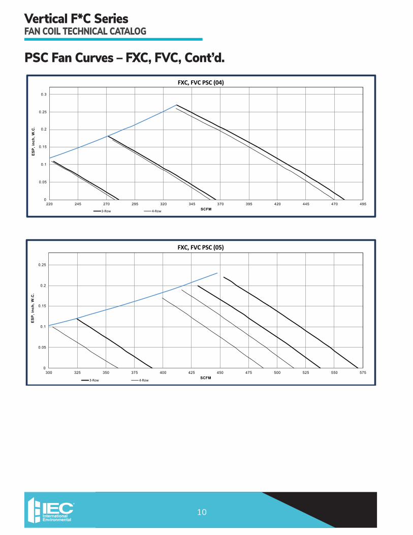
PSC Fan Curves – FXC, FVC, Cont’d.
0
0.05
0.1
0.15
0.2
0.25
0.3
220 245 270 295 320 345 370 395 420 445 470 495
ES
P, i
nch,
W.C
.
SCFM
FXC, FVC PSC (04)
3-Row 4-Row
0
0.05
0.1
0.15
0.2
0.25
300 325 350 375 400 425 450 475 500 525 550 575
ES
P, i
nch,
W.C
.
SCFM
FXC, FVC PSC (05)
3-Row 4-Row

Vertical F*C SeriesFAN COIL TECHNICAL CATALOG
11
PSC Fan Curves – FXC, FVC, Cont’d.
0
0.05
0.1
0.15
0.2
0.25
0.3
320 330 340 305 360 370 380 390 400 410 420 430 440 450 460 470 480 490 500 510 520 530 540 550 560 570 580 590 600 610 620 630 640
ES
P, i
nch,
W.C
.
SCFM
FXC, FVC PSC (06)
3-Row 4-Row
0
0.05
0.1
0.15
0.2
0.25
0.3
0.35
250 275 300 325 350 375 400 425 450 475 500 525 550 575 600 625 650 675 700
ES
P, i
nch,
W.C
.
SCFM
FXC, FVC PSC (08)
3-Row 4-Row

Vertical F*C SeriesFAN COIL TECHNICAL CATALOG
12
PSC Fan Curves – FXC, FVC, Cont’d.
0
0.05
0.1
0.15
0.2
0.25
0.3
400 425 450 475 500 525 550 575 600 625 650 675 700 725 750 775 800 825 850 875 900
ES
P, i
nch,
W.C
.
SCFM
FXC, FVC PSC (10)
3-Row 4-Row
0
0.05
0.1
0.15
0.2
0.25
630 655 680 705 730 755 780 805 830 855 880 905 930 955 980 1005 1030 1055 1080
ES
P, i
nch,
W.C
.
SCFM
FXC, FVC PSC (12)
3-Row 4-Row

Vertical F*C SeriesFAN COIL TECHNICAL CATALOG
13
FHC02 - 115V, PSC
3-Row 4-Row
ESP,
inch
, W.C
.
SCFM
0
0.05
0.1
0.15
0.2
0.25
0.3
90 100 110 120 130 140 150 160 170 180 190 200 210 220 230
PSC Fan Curves – FHC
FHC03 - 115V, PSC
3-Row 4-Row
ESP,
inch
, W.C
.
SCFM
0
0.05
0.1
0.15
0.2
0.25
0.3
130 140 150 170 180 190 210 220 240 250 260 280 290 300 320160 200 230 270 310

Vertical F*C SeriesFAN COIL TECHNICAL CATALOG
14
PSC Fan Curves – FHC, Cont’d.FHC04 - 115V, PSC
3-Row 4-Row
ESP,
inch
, W.C
.
SCFM
0
0.05
0.1
0.15
0.2
0.25
0.3
180 190 200 250 270 290 330 350 390 400 420 460 470 500 540230 310 370 440 520
0.35
0.4
210 220 240 260 280 300 320 340 360 380 410 430 450 480 490 510 530
FHC05 - 115V, PSC
3-Row 4-Row
ESP,
inch
, W.C
.
SCFM
0
0.05
0.1
0.15
0.2
0.25
310 320 360 390 420 440 470 490 520 530 550 580350 410 450330 340 370 380 400 430 460 480 500 510 540 560 570

Vertical F*C SeriesFAN COIL TECHNICAL CATALOG
15
PSC Fan Curves – FHC, Cont’d.FHC06 - 115V, PSC
3-Row 4-Row
ESP,
inch
, W.C
.
SCFM
0
0.05
0.1
0.15
0.2
0.25
300 310 360 390 420 460 490 520 560 570 590 630350 410 470320 330 370 380 400 430 480 510 530 540 580 600 620
0.3
340 440 450 500 550 610
FHC08 - 115V, PSC
3-Row 4-Row
ESP,
inch
, W.C
.
SCFM
0
0.05
0.1
0.15
0.2
0.25
280 355 430 480 555 605305 380 405 505 580 630 655 680
0.3
330 455 530
0.35

Vertical F*C SeriesFAN COIL TECHNICAL CATALOG
16
PSC Fan Curves – FHC, Cont’d.FHC10 - 115V, PSC
3-Row 4-Row
ESP,
inch
, W.C
.
SCFM
0
0.05
0.1
0.15
0.2
0.25
450 550 650 725 825 900475 575 625 750 850 925 975 1000
0.3
500 700 800525 600 675 775 875 950 1025
FHC12 - 115V, PSC
3-Row 4-Row
ESP,
inch
, W.C
.
SCFM
0
0.05
0.1
0.15
0.2
0.25
650 825 875 1025675 750 800 900 975 1050 1075 1100700 850 950725 775 925 1000 1125

Vertical F*C SeriesFAN COIL TECHNICAL CATALOG
17
ECM Fan Curves – FXC, FVC
0
0.05
0.1
0.15
0.2
0.25
0.3
0.35
0.4
70 95 120 145 170 195 220 245
ES
P, i
nch,
W.C
.
SCFM
FXC, FVC ECM (02)
3-Row 4-Row Max Speed w/Min Rows
DO NOT APPLY ELECTRICHEAT IN THIS REGION
0
0.05
0.1
0.15
0.2
0.25
0.3
140 165 190 215 240 265 290 315
ES
P, i
nch,
W.C
.
SCFM
FXC, FVC ECM (03)
3-Row 4-Row Max Speed w/Min Rows
DO NOT APPLY ELECTRICHEAT IN THIS REGION

Vertical F*C SeriesFAN COIL TECHNICAL CATALOG
18
ECM Fan Curves – FXC, FVC, Cont’d.
0
0.05
0.1
0.15
0.2
0.25
0.3
220 245 270 295 320 345 370 395 420 445 470 495 520
ES
P, i
nch,
W.C
.
SCFM
FXC, FVC ECM (04)
3-Row 4-Row Max Speed w/Min Rows
DO NOT APPLY ELECTRICHEAT IN THIS REGION
0
0.05
0.1
0.15
0.2
0.25
0.3
260 285 310 335 360 385 410 435 460 485 510 535 560 585 610
ES
P, i
nch,
W.C
.
SCFM
FXC, FVC ECM (05)
3-Row 4-Row Max Speed w/Min Rows
DO NOT APPLY ELECTRICHEAT IN THIS REGION

Vertical F*C SeriesFAN COIL TECHNICAL CATALOG
19
ECM Fan Curves – FXC, FVC, Cont’d.
0
0.05
0.1
0.15
0.2
0.25
0.3
0.35
310 335 360 385 410 435 460 485 510 535 560 585 610 635 660 685 710
ES
P, i
nch,
W.C
.
SCFM
FXC, FVC ECM (06)
3-Row 4-Row Max Speed w/Min Rows
DO NOT APPLY ELECTRICHEAT IN THIS REGION
0
0.05
0.1
0.15
0.2
0.25
0.3
350 375 400 425 450 475 500 525 550 575 600 625 650 675 700 725 750 775 800 825 850
ES
P, i
nch,
W.C
.
SCFM
FXC, FVC ECM (08)
3-Row 4-Row Max Speed w/Min Rows
DO NOT APPLY ELECTRICHEAT IN THIS REGION

Vertical F*C SeriesFAN COIL TECHNICAL CATALOG
20
ECM Fan Curves – FXC, FVC, Cont’d.
0
0.05
0.1
0.15
0.2
0.25
0.3
500 525 550 575 600 625 650 675 700 725 750 775 800 825 850 875 900 925 950 975 1000 1025 1050 1075 1100 1125
ES
P, i
nch,
W.C
.
SCFM
FXC, FVC ECM (10)
3-Row 4-Row Max Speed w/Min Rows
DO NOT APPLY ELECTRICHEAT IN THIS REGION
0
0.05
0.1
0.15
0.2
0.25
0.3
600 625 650 675 700 725 750 775 800 825 850 875 900 925 950 975 1000 1025 1050 1075 1100 1125 1150 1075 1200 1225 1250 1275 1300
ES
P, i
nch,
W.C
.
SCFM
FXC, FVC ECM (12)
3-Row 4-Row Max Speed w/Min Rows
DO NOT APPLY ELECTRICHEAT IN THIS REGION

Vertical F*C SeriesFAN COIL TECHNICAL CATALOG
21
ECM Fan Curves – FHCFHC02 - 115V, ECM
3-Row 4-Row
ESP,
inch
, W.C
.
SCFM
0
0.05
0.1
0.15
0.2
0.25
50 130 150 22060 90 110 160 190 230 240 25070 140 18080 100 170 200 260
Max Speed w/Min Rows
0.3
120 210
FHC03 - 115V, ECM
3-Row 4-Row
ESP,
inch
, W.C
.
SCFM
0
0.05
0.1
0.15
0.2
0.25
110 200 220 300120 160 180 230 270 310 330 340130 210 260140 170 250 280 350
Max Speed w/Min Rows
0.3
190 290
0.35
0.4
150 240 320

Vertical F*C SeriesFAN COIL TECHNICAL CATALOG
22
ECM Fan Curves – FHC, Cont’d.FHC04 - 115V, ECM
3-Row 4-Row
ESP,
inch
, W.C
.
SCFM
0
0.05
0.1
0.15
0.2
0.25
210 340 370 490220 280 310 390 450 510 540 550230 360 430260 300 420 460 570
Max Speed w/Min Rows
0.3
330 480
0.35
270 400 520240 250 290 320 350 380 410 440 470 500 530 560
FHC05 - 115V, ECM
3-Row 4-Row
ESP,
inch
, W.C
.
SCFM
0
0.05
0.1
0.15
0.2
0.25
260 390 420 540270 330 360 440 500 560 600 610280 410 480310 350 470 510 630
Max Speed w/Min Rows
0.3
380 530
0.35
320 450 570290 300 340 370 400 430 460 490 520 550 580 620590

Vertical F*C SeriesFAN COIL TECHNICAL CATALOG
23
ECM Fan Curves – FHC, Cont’d.FHC06 - 115V, ECM
3-Row 4-Row
ESP,
inch
, W.C
.
SCFM
0
0.05
0.1
0.15
0.2
0.25
310 440 470 590320 380 410 490 550 610 650 660330 460 530360 400 520 560 690
Max Speed w/Min Rows
0.3
430 580
0.35
370 500 620340 350 390 420 450 480 510 540 570 600 630 680640 670
FHC08 - 115V, ECM
3-Row 4-Row
ESP,
inch
, W.C
.
SCFM
0
0.05
0.1
0.15
0.2
0.25
370 545 770 820395 570495 645 695 870
Max Speed w/Min Rows
0.3
520 720445 620420 470 595 670 745 795 845

Vertical F*C SeriesFAN COIL TECHNICAL CATALOG
24
ECM Fan Curves – FHC, Cont’d.FHC10 - 115V, ECM
3-Row 4-Row
ESP,
inch
, W.C
.
SCFM
0
0.05
0.1
0.15
0.2
0.25
460 685 985 1060485 735635 835 885 1110
Max Speed w/Min Rows
0.3
660 935560 785510 585 760 860 960 1035 1085
0.35
535 610 710 810 910 1010
FHC12 - 115V, ECM
3-Row 4-Row
ESP,
inch
, W.C
.
SCFM
0
0.05
0.1
0.15
0.2
0.25
620 870 1195 1270645 920820 1020 1070 1320
Max Speed w/Min Rows
0.3
845 1145720 970670 745 945 1045 1170 1245 1295695 795 895 995 1120 1220770 1095 1345

Vertical F*C SeriesFAN COIL TECHNICAL CATALOG
25
Motor Performance DataThermal Overload ProtectionAll split-capacitor motors furnished by IEC contain internal thermal-overload protection. The overload automatically resets when the temperature returns to a safe limit. Electronics Testing Laboratories, Inc. (ETL) approves the motor and thermal overload combination at locked rotor conditions only.
PSC Motor Performance Data — FXC, FVC - 3 Row Coil
Voltage Fan SpeedUnit Size 02 03 04 05 06 08 10 12
Nominal HP 1/40 1/30 1/12 1/6 1/6 1/6 (2)-1/12 (2)-1/6Amps 0.40 0.80 1.60 2.50 2.50 2.50 3.20 5.00
115V60 Hz
1-Phase
HighWatts
57 77 119 206 185 191 259 336Medium 52 65 83 124 146 146 174 254
Low 43 49 62 73 88 80 131 159
208V60 Hz
1-Phase
HighWatts
46 87 102 178 148 154 224 269Medium 39 62 79 84 100 98 173 189
Low 33 30 52 63 60 53 110 117
230V60 Hz
1-Phase
HighWatts
53 104 116 235 161 170 257 293Medium 45 73 90 95 113 112 197 211
Low 40 35 60 71 71 64 130 138
277V60 Hz
1-Phase
HighWatts
50 82 137 96 156 195 272 354Medium 41 61 102 69 140 133 215 249
Low 33 47 74 67 115 107 139 212
NOTES: 1. Total unit PSC motor Amps and Watts are shown. (Consult factory for ECM motor amps and watts). 2. Consult factory for 50 Hz applications.
VoltageUnit Size F**02 F**03 F**04 F**06 F**08 F**10 F**12
Nominal HP 1/7 1/7 1/6 1/6 1/6 (2) 1/6 (2) 1/6
120VRated Motor FLA 2.3 2.3 2.4 2.4 2.4 2.4, 2.4 2.4, 2.4
Max Program Current 1.2 1.4 1.5 2.2 2.4 2.0, 2.0 2.4, 2.4
208-240VRated Motor FLA 1.4 1.4 1.6 1.6 1.6 1.6, 1.6 1.6, 1.6
Max Program Current 0.7 0.9 21.0 1.4 1.6 1.3, 1.3 1.6, 1.6
277VRated Motor FLA 1.2 1.2 1.3 1.3 1.3 1.3, 1.3 1.3, 1.3
Max Program Current 0.6 0.7 0.8 1.2 1.3 1.1, 1.1 1.3, 1.3
EC Motor Performance Data — Vertical F**, Standard Performance
PSC Motor Performance Data — FHC - 3 Row Coil
Voltage Fan SpeedUnit Size 02 03 04 05 06 08 10 12
Nominal HP 1/40 1/30 1/12 1/6 1/6 1/6 (2)-1/12 (2)-1/6Amps 0.40 0.80 1.60 2.50 2.50 2.50 3.20 5.00
115V60 Hz
1-Phase
HighWatts
48 79 145 218 184 185 266 339Medium 43 49 87 128 142 142 175 259
Low 35 36 54 73 85 77 134 161
208V60 Hz
1-Phase
HighWatts
67 94 104 173 148 151 216 268Medium 61 73 78 86 101 97 169 190
Low 55 50 45 65 59 52 110 117
230V60 Hz
1-Phase
HighWatts
67 94 104 173 148 151 216 268Medium 61 73 78 86 101 97 169 190
Low 55 50 45 65 59 52 110 117
277V60 Hz
1-Phase
HighWatts
50 83 136 96 172 194 274 350Medium 41 62 107 72 131 132 219 247
Low 33 48 68 70 110 106 141 212

Vertical F*C SeriesFAN COIL TECHNICAL CATALOG
26
Sound Power Data
NOTES: 1. Casing Radiated Testing per AHRI 350-2008: 4.2.2.3 Casing radiated with free inlet, Sound Rating of Ducted Air Moving and Conditioning Equipment. 2. UnitTestConfiguration:BottomReturn/StampedLouverTopSupply,3Row3/8”12FPICoil,115VACPSCMotor,1/2”dualdensityfigerglassinsulation. 3. Sound power data is expressed in decibels, dB RE: 1 x 10-12 w (picowatts).
UNIT SIZE RATING FAN SPEED CFM
SOUND POWER LEVEL, Lw (dB reference one picowatt) A-wgt (dBA)125 Hz 250 Hz 500 Hz 1K Hz 2K Hz 4K Hz 8K Hz
2 CASING RADIATED
H 245 56 60 52 46 42 36 35 54
M 210 54 57 48 41 38 31 35 51
L 145 48 46 40 33 28 29 34 43
3 CASING RADIATED
H 315 59 63 57 55 47 43 38 60
M 260 54 57 54 47 40 35 35 54
L 225 50 51 49 40 32 30 35 49
4 CASING RADIATED
H 485 62 68 60 56 51 46 41 63
M 350 56 63 53 49 43 37 35 56
L 280 54 52 47 44 35 31 34 49
5 CASING RADIATED
H 575 70 68 62 58 52 48 43 64
M 530 67 66 60 57 50 46 41 63
L 385 64 60 54 48 41 36 36 55
6 CASING RADIATED
H 630 66 69 62 59 52 48 42 65
M 555 65 67 60 56 50 45 39 62
L 385 59 54 50 44 36 61 35 51
8 CASING RADIATED
H 690 66 69 63 60 54 51 46 66
M 605 66 71 61 58 52 48 43 65
L 375 63 60 54 47 41 34 35 55
10 CASING RADIATED
H 970 64 67 64 60 54 49 42 65
M 725 58 62 58 52 45 38 35 58
L 590 54 56 52 45 38 32 34 52
12 CASING RADIATED
H 1165 68 72 66 62 56 52 47 69
M 1030 68 72 64 60 54 49 44 67
L 735 65 63 56 50 43 37 34 57
FXC, FVC, FHC Sound Power Data

Vertical F*C SeriesFAN COIL TECHNICAL CATALOG
27
Electric HeatingElectric heaters are available on IEC Vertical Series fan coil units for the following applications.
Total Electric HeatTotal electric heat eliminates the requirement for a boiler. Heatingand/orcoolingmaybeavailableonanindividualbasis throughout the year. Two-pipe chilled water is used for cooling, and the electric heater is used for heating. Individual room controls can be supplied for either manual or automatic changeover.
Auxiliary Electric HeatAuxiliary electric heat is ideal for tempering room air between seasons and during the cooling season when chilled water is being circulated. Individual room controls are supplied to provide electric heat only when chilled water is being circulated. During the regular heating season, heating is provided by hot water being circulated in the system.
ConstructionThe heater coils of high-grade resistance wire are supported by ceramic insulators on plated steel brackets. These heat elements are suspended directly in front of the fan outlet between the blower and the coil. High limit thermal cutouts protect the heater in the event of air failure. There are many special applications and control sequences for electric heat. For special applications, please consult the factory.
Voltage kWUnit Size
02 03 04 05 06 08 10 12
120V
1.0 - - -
1.5 - - - -
2.0 - - - -
3.0 - - -
208V 240V
220/240V 50Hz
1.0 - - -
1.5 - - - -
2.0 - - - -
3.0 - - -
4.0 - - - - -
277V
1.0 - - -
1.5 - - - -
2.0 - - - -
3.0 - - -
4.0 - - - - -
5.0 - - - - - -
6.0 - - - - - - -
NOTES: 1. All heaters are single stage and single phase. 2. Electric heater available with top or front discharge. 3. Electric Heating Capacities (BTUH) = Heater kW x 3413. 4. ElectricHeaterAmerpage=(HeaterkWx1000)/AppliedVoltage.
Electric Heater Selection

Vertical F*C SeriesFAN COIL TECHNICAL CATALOG
28
Submittal DataFHC – Vertical Hideaway Unit with Top Supply
Unit ModelDimensions – Inches (Millimeters) Quantity/Unit Unit
Weight*A B C D E F Blower Motor
FHC02 23-1/2(597) 22 (559) 23 (584) 16 (406) 7-3/4(197) 8 (203) 1 1 42
FHC03 23-1/2(597) 22 (559) 23 (584) 18 (457) 7-3/4(197) 8 (203) 1 1 47
FHC04 33-1/2(851) 32 (813) 33 (838) 26 (660) 10-3/4(273) 12 (305) 2 1 57
FHC05 33-1/2(851) 32 (813) 33 (838) 26 (660) 10-3/4(273) 12 (305) 2 1 60
FHC06 43-1/2(1105) 42 (1067) 43 (1092) 36 (914) 14-3/4(375) 14 (356) 2 1 77
FHC08 45-1/2(1156) 44 (1118) 45 (1143) 38 (965) 13-3/4(349) 18 (457) 2 1 79
FHC10 59-1/2(1511) 58 (1473) 59 (1499) 52 (1321) 16-1/4(413) 27 (686) 4 2 108
FHC12 67-1/2(1715) 66 (1676) 67 (1702) 60 (1524) 16-1/4(413) 27 (686) 4 2 127
NOTES: 1. RH shown, LH opposite. 2. Alldimensionsare+/-1/4”(6). 3. Product specifications are subject to changes without notice. * Unit weights (shown in pounds) are based on dry coils, minimum rows and exclude packaging, valves or other components. ** 3-3/4(95)forallmodelswiththeexclusionofthe300whichis2-3/4(70).
Drawing is provided for reference only. Dimensions may vary with options ordered. Consult IEC website for submittal drawings.

Vertical F*C SeriesFAN COIL TECHNICAL CATALOG
29
Submittal Data, Cont’d.
Unit ModelDimensions – Inches (Millimeters) Quantity/Unit Unit
Weight**A B C D E F Blower Motor
FHC02 23-1/2(597) 22 (559) 23 (584) 16 (406) 7-3/4(197) 8 (203) 1 1 42
FHC03 23-1/2(597) 22 (559) 23 (584) 18 (457) 7-3/4(197) 8 (203) 1 1 47
FHC04 33-1/2(851) 32 (813) 33 (838) 26 (660) 10-3/4(273) 12 (35) 2 1 57
FHC05 33-1/2(851) 32 (813) 33 (838) 26 (660) 10-3/4(273) 12 (305) 2 1 60
FHC06 43-1/2(1105) 42 (1067) 43 (1092) 36 (914) 14-3/4(375) 14 (346) 2 1 77
FHC08 45-1/2(1156) 44 (1118) 45 (1143) 38 (965) 13-3/4(349) 18 (457) 2 1 79
FHC10 59-1/2(1511) 58 (1473) 59 (1499) 52 (1321) 16-1/4(413) 27 (686) 4 2 108
FHC12 67-1/2(1715) 66 (1676) 67 (1702) 60 (1524) 16-1/4(413) 27 (686) 4 2 127
FHC – Vertical Hideaway Unit with Front Supply
NOTES: 1. RH shown, LH opposite. 2. Alldimensionsare+/-1/4”(6). 3. Product specifications are subject to changes without notice. * Unit weights (shown in pounds) are based on dry coils, minimum rows and exclude packaging, valves or other components. ** 3-3/4(95)forallmodelswiththeexclusionofthe300whichis2-3/4(70).
Drawing is provided for reference only. Dimensions may vary with options ordered. Consult IEC website for submittal drawings.

Vertical F*C SeriesFAN COIL TECHNICAL CATALOG
30
Submittal Data, Cont’d.FHC – Vertical Hideaway Unit with Electric Heat
NOTES: 1. RH shown, LH opposite. 2. Alldimensionsare+/-1/4”(6). 3. Product specifications are subject to changes without notice. * Unit weights (shown in pounds) are based on dry coils, minimum rows and exclude packaging, valves or other components. ** 3-3/4(95)forallmodelswiththeexclusionofthe300whichis2-3/4(70).
Drawing is provided for reference only. Dimensions may vary with options ordered. Consult IEC website for submittal drawings.
Unit ModelDimensions – Inches (Millimeters) Quantity/Unit Unit
Weight*A B C D E F Blower Motor
FHC02 23-1/2(597) 22 (559) 23 (584) 16 (406) 7-3/4(197) 8 (203) 1 1 44
FHC03 23-1/2(597) 22 (559) 23 (584) 18 (457) 7-3/4(197) 8 (203) 1 1 49
FHC04 33-1/2(851) 32 (813) 33 (838) 26 (660) 10-3/4(273) 12 (305) 2 1 59
FHC05 33-1/2(851) 32 (813) 33 (838) 26 (660) 10-3/4(273) 12 (305) 2 1 62
FHC06 43-1/2(1105) 42 (1067) 43 (1092) 36 (914) 14-3/4(375) 14 (356) 2 1 80
FHC08 45-1/2(1156 44 (1118) 45 (1143) 38 (965) 13-3/4(349) 18 (457) 2 1 82
FHC10 59-1/2(1511) 58 (1473) 59 (1499) 52 (1321) 16-1/4(413) 27 (686) 4 2 111
FHC12 67-1/2(1715) 66 (1676) 67 (1702) 60 (1524) 16-1/4(413) 27 (686) 4 2 130

Vertical F*C SeriesFAN COIL TECHNICAL CATALOG
31
Submittal Data, Cont’d.FXC – Vertical Cabinet
NOTES: 1. RH shown, LH opposite. 2. Alldimensionsare+/-1/4”(6). 3. Product specifications are subject to changes without notice. * Unit weights (shown in pounds) are based on dry coils, minimum rows and exclude packaging, valves or other components.
Drawing is provided for reference only. Dimensions may vary with options ordered. Consult IEC website for submittal drawings.
Unit ModelDimensions – Inches (Millimeters) Quantity/Unit Unit
Weight*A B C D E F H Blower Motor
FXC02 41 (1041) 22 (559) 23 (584) 17-1/4(438) 3-1/8(79) 8 (203) 16-1/2(419) 1 1 63
FXC03 41 (1041) 22 (559) 23 (584) 17-1/4(438) 3-1/8(79) 8 (203) 16-1/2(419) 1 1 68
FXC04 51 (1295) 32 (813) 33 (838) 26 (660) 3-3/4(95) 12 (305) 19-1/2(495) 2 1 82
FXC05 51 (1295) 32 (813) 33 (838) 26 (660) 3-3/4(95) 12 (305) 19-1/2(495) 2 1 85
FXC06 61 (1549) 42 (1067) 43 (1092) 39 (991) 2-1/4(57) 14 (356) 23-1/2(597) 2 1 99
FXC08 63 (1600) 44 (1118) 45 (1143) 39 (991) 3-1/4(83) 18 (457) 22-1/2(572) 2 1 101
FXC10 77 (1956) 58 (1473) 59 (1499) 52-1/8(1324) 3-5/8(92) 27 (686) 25 (638) 4 2 133
FXC12 85 (2159) 66 (1676) 67 (1702) 61 (1549) 3-1/4(83) 27 (686) 29 (737) 4 2 154

Vertical F*C SeriesFAN COIL TECHNICAL CATALOG
32
Submittal Data, Cont’d.FXC – Vertical Cabinet with Electric Heat
NOTES: 1. RH shown, LH opposite. 2. Alldimensionsare+/-1/4”(6). 3. Product specifications are subject to changes without notice. * Unit weights (shown in pounds) are based on dry coils, minimum rows and exclude packaging, valves or other components.
Drawing is provided for reference only. Dimensions may vary with options ordered. Consult IEC website for submittal drawings.
Unit ModelDimensions – Inches (Millimeters) Quantity/Unit Unit
Weight*A B C D E F H Blower Motor
FXC02 41 (1041) 22 (559) 23 (584) 17-1/4(438) 3-1/8(79) 8 (203) 16-1/2(419) 1 1 65
FXC03 41 (1041) 22 (559) 23 (584) 17-1/4(438) 3-1/8(79) 8 (203) 16-1/2(419) 1 1 70
FXC04 51 (1295) 32 (813) 33 (838) 26 (660) 3-3/4(95) 12 (305) 19-1/2(495) 2 1 84
FXC05 51 (1295) 32 (813) 33 (838) 26 (660) 3-3/4(95) 12 (305) 19-1/2(495) 2 1 87
FXC06 61 (1549) 42 (1067) 43 (1092) 39 (991) 2-1/4(57) 14 (356) 23-1/2(597) 2 1 102
FXC08 63 (1600) 44 (1118) 45 (1143) 39 (991) 3-1/4(83) 18 (457) 22-1/2(572) 2 1 104
FXC10 77 (1956) 58 (1473) 59 (1499) 52-1/8(1324) 3-5/8(92) 27 (686) 25 (635) 4 2 136
FXC12 85 (2159) 66 (1676) 67 (1702) 61 (1549) 3-1/4(83) 27 (686) 29 (737) 4 2 157

Vertical F*C SeriesFAN COIL TECHNICAL CATALOG
33
FXC – Vertical Cabinet with Front Supply
NOTES: 1. RH shown, LH opposite. 2. Alldimensionsare+/-1/4”(6). 3. Product specifications are subject to changes without notice. * Unit weights (shown in pounds) are based on dry coils, minimum rows and exclude packaging, valves or other components.
Drawing is provided for reference only. Dimensions may vary with options ordered. Consult IEC website for submittal drawings.
Unit ModelDimensions – Inches (Millimeters) Quantity/Unit Unit
Weight*A B C D E F H Blower Motor
FXC02 41 (1041) 22 (559) 23 (584) 17-1/4(438) 3-1/8(79) 8 (203) 16-1/2(419) 1 1 63
FXC03 41 (1041) 22 (559) 23 (584) 17-1/4(438) 3-1/8(79) 8 (203) 16-1/2(419) 1 1 68
FXC04 51 (1295) 32 (813) 33 (838) 26 (660) 3-3/4(95) 12 (305) 19-1/2(495) 2 1 82
FXC05 51 (1295) 32 (813) 33 (838) 26 (660) 3-3/4(95) 12 (305) 19-1/2(495) 2 1 85
FXC06 61 (1549) 42 (1067) 43 (1092) 39 (991) 2-1/4(57) 14 (356) 23-1/2(597) 2 1 99
FXC08 63 (1600) 44 (1118) 45 (1143) 39 (991) 3-1/4(83) 18 (457) 22-1/2(572) 2 1 101
FXC10 77 (1956) 58 (1473) 59 (1499) 52-1/8(1324) 3-5/8(92) 27 (686) 25 (638) 4 2 133
FXC12 85 (2159) 66 (1676) 67 (1702) 61 (1549) 3-1/4(83) 27 (686) 29 (737) 4 2 154
Submittal Data, Cont’d.

Vertical F*C SeriesFAN COIL TECHNICAL CATALOG
34
Submittal Data, Cont’d.FVC – Vertical Sloped Top Cabinet
NOTES: 1. RH shown, LH opposite. 2. Alldimensionsare+/-1/4”(6). 3. Product specifications are subject to changes without notice. * Unit weights (shown in pounds) are based on dry coils, minimum rows and exclude packaging, valves or other components.
Drawing is provided for reference only. Dimensions may vary with options ordered. Consult IEC website for submittal drawings.
Unit ModelDimensions – Inches (Millimeters) Quantity/Unit Unit
Weight*A B C D E F H Blower Motor
FVC02 41 (1041) 22 (559) 23 (584) 17-1/4(438) 3-1/8(79) 8 (203) 16-1/2(419) 1 1 64
FVC03 41 (1041) 22 (559) 23 (584) 17-1/4(438) 3-1/8(79) 8 (203) 16-1/2(419) 1 1 69
FVC04 51 (1295) 32 (813) 33 (838) 26 (660) 3-3/4(95) 12 (305) 19-1/2(495) 2 1 83
FVC05 51 (1295) 32 (813) 33 (838) 26 (660) 3-3/4(95) 12 (305) 19-1/2(495) 2 1 86
FVC06 61 (1549) 42 (1067) 43 (1092) 39 (991) 2-1/4(57) 14 (356) 23-1/2(597) 2 1 100
FVC08 63 (1600) 44 (1118) 45 (1143) 39 (991) 3-1/4(83) 18 (457) 22-1/2(572) 2 1 102
FVC10 77 (1956) 58 (1473) 59 (1499) 52-1/8(1324) 3-5/8(92) 25 (635) 25 (635) 4 2 135
FVC12 85 (2159) 66 (1676) 67 (1702) 61 (1549) 3-1/4(83) 29 (737) 29 (737) 4 2 156
Vertical F*C SeriesFAN COIL TECHNICAL CATALOG
35
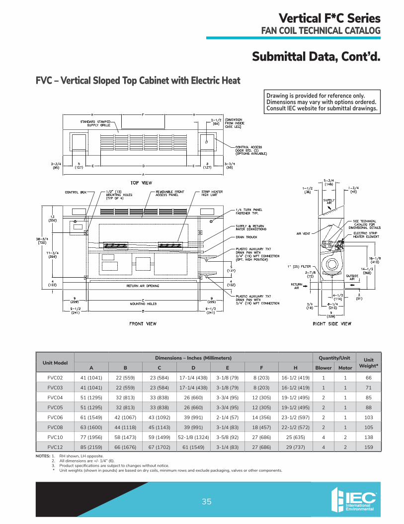
Submittal Data, Cont’d.FVC – Vertical Sloped Top Cabinet with Electric Heat
NOTES: 1. RH shown, LH opposite. 2. Alldimensionsare+/-1/4”(6). 3. Product specifications are subject to changes without notice. * Unit weights (shown in pounds) are based on dry coils, minimum rows and exclude packaging, valves or other components.
Drawing is provided for reference only. Dimensions may vary with options ordered. Consult IEC website for submittal drawings.
Unit ModelDimensions – Inches (Millimeters) Quantity/Unit Unit
Weight*A B C D E F H Blower Motor
FVC02 41 (1041) 22 (559) 23 (584) 17-1/4(438) 3-1/8(79) 8 (203) 16-1/2(419) 1 1 66
FVC03 41 (1041) 22 (559) 23 (584) 17-1/4(438) 3-1/8(79) 8 (203) 16-1/2(419) 1 1 71
FVC04 51 (1295) 32 (813) 33 (838) 26 (660) 3-3/4(95) 12 (305) 19-1/2(495) 2 1 85
FVC05 51 (1295) 32 (813) 33 (838) 26 (660) 3-3/4(95) 12 (305) 19-1/2(495) 2 1 88
FVC06 61 (1549) 42 (1067) 43 (1092) 39 (991) 2-1/4(57) 14 (356) 23-1/2(597) 2 1 103
FVC08 63 (1600) 44 (1118) 45 (1143) 39 (991) 3-1/4(83) 18 (457) 22-1/2(572) 2 1 105
FVC10 77 (1956) 58 (1473) 59 (1499) 52-1/8(1324) 3-5/8(92) 27 (686) 25 (635) 4 2 138
FVC12 85 (2159) 66 (1676) 67 (1702) 61 (1549) 3-1/4(83) 27 (686) 29 (737) 4 2 159

Vertical F*C SeriesFAN COIL TECHNICAL CATALOG
36
Submittal Data, Cont’d.
NOTES:1. Alldimensionsare+/-1/4”(6). 2. Product specifications are subject to change without notice. 3. Same side coil connections shown. Consult factory for opposite end applications.
RIGHT-HAND CONNECTIONS VIEWLEFT-HAND CONNECTIONS VIEW
AIR VENT
14-1/2(368)
16-1/8(410)
4-1/4 (108)
7-3/8 (187)
AIR VENT
14-1/2(368)
16-1/8(410)
4-1/4 (108)
7-3/8 (187)
HR
HS
CS
CR
HR
HS
CS
CR
Ø3/8 (9.7) TYP
Unit ModelQuantity/Unit
Blower Motor
02 1 1
03 1 1
04 2 1
05 2 1
06 2 1
08 2 1
10 4 2
12 4 2
HR - Hot Water ReturnHS - Hot Water SupplyCR - Cold Water ReturnCS - Cold Water Supply

Vertical F*C SeriesFAN COIL TECHNICAL CATALOG
37
Standard Features, Options and AccessoriesFeatures and Options Standard Factory Field Installed Factory Special
Air Flow Arrangements
FrontReturn/TopSupply(FHC,FXC,FVC) X
FrontReturn/FrontSupply(FHC,FXC,FVC) X
Coils
3-Rows 2-Pipe (FHC, FXC, FVC) X X
3/1,3/2,4/0,or4/1-Rows(FHC,FXC,FVC) X
Manual Air Vent X
Automatic Air Vent X
Connection
Right or Left (Same End Standard, Opposite End Optional) X X
Drain Pan
Painted, Galvanized Externally Coated with a 2-part Closed Cell Foam X
Stainless Steel Externally Coated X
Plastic Auxiliary Drain Pan X
Fin Material
Aluminumw/GalvanizedEndSheets X
Copperw/StainlessEndSheets&BottomCoilBaffle X
Nichrome Wire Strip Electric Heater (Total and Auxiliary) X
Filters
1”ThrowawayNon-WovenSynthetic X
1”Permanent X
1”MERV8Pleated X
1”MERV13Pleated X
2”MERV8Pleated X
2”MERV13Pleated X
Insulation
1/2”StandardFiberglass X
1/2”PremiumIAQFiberglass X
1/2”FoilFace X
1/4”ClosedCell X
Motor Type
PSCMotorsw/QuickConnectPlug(FHC,FXC,FVC) X
Constant Torque ECM Motors (FHC, FXC, FVC) X
Motor Voltage
115/1/603-Speed X
208/230/277/1/60,220/1/503-Speed X
Supply/Return Air Grilles
Stamped Supply Grille (FXC, FVC) X
DoubleDeflectionIntegralSupplyGrille,Painted(FXC,FVC) X
DoubleDeflectionAluminumSupplyGrille(FXC,FVC) X
Stamped Return Grille (FXC, FVC) X

Vertical F*C SeriesFAN COIL TECHNICAL CATALOG
38
Standard Features, Options and Accessories, Cont’d.Features and Options Standard Factory Field Installed Factory Special
Controls
Service Switch with Lockout Tabs X
Single Point Power Connection X
Incoming Power Fusing X
24V Controls X
Three Speed Switch X
Condensate Float Switch X
OutsideAirDampers/WallPanels
Manually Controlled Damper (FHC, FXC, FVC) X
Motorized Controlled Damper (FHC, FXC, FVC) X
Outside Air Box (FHC, FXC, FVC) X
Decorative Framed Wall Panels X
Thermostats
Unit Mounted 156 Series X
Wall Mounted 155 Vertical Wall Series X
24V Digital Non-Programmable X X
24V Digital Programmable X X
24V Proportional 7-Day X X
24V Proportional BACnet X X
Tamperproof Locks (Camlock)
Access Panels (FXC, FVC) X
Access Doors (FXC, FVC) X

Vertical F*C SeriesFAN COIL TECHNICAL CATALOG
39
FiltersAll Vertical FHC, FXC, FVC Series units include a non-woven,syntheticthrowawayfilter,designedtomaximizeairflowandperformance.Permanent(cleanable),MERV8orMERV13filtersarealsoavailable as factory-installed options.
NOTES: Sizes shown are nominal ordering sizes
Unit SizeNominal One-Inch Filter Size – Inches (Millimeters)
FHC, FXC, FVC
02 7-3/4”x21-3/4”(197x552)
03 7-3/4”x21-3/4”(197x552)
04 7-3/4”x31-3/4”(197x806)
05 7-3/4”x31-3/4”(197x806)
06 7-3/4”x41-3/4”(197x1060)
08 7-3/4”x43-3/4”(197x1111)
10 7-3/4”x57-3/4”(197x1467)
12 7-3/4”x65-3/4”(197x1670)
Standard Features, Options, and Accessories, Cont’d.

Vertical F*C SeriesFAN COIL TECHNICAL CATALOG
40
Standard Features, Options and Accessories, Cont’d.Control PackagesControlsAs detailed in the table below, we offer a wide variety of control schemes to meet the most basic to the most demanding operating logic.
Three-speed Fan ControlAll of our basic control schemes utilize a 3-speed fan control, which allows for maximum performance when load demand is at its peak, and sound reduction through lower speeds, when less capacity is needed.
Low Voltage Control (24 V)A low voltage control is available with all of our control schemes.
Condensate Float SwitchThis switch shuts down the unit when the water level in the drain pan reaches an unsafe level. New versions of building codes across the US are constantly being adopted, and may require this type of device.
Service SwitchesWe offer service switches for use by maintenance and service personnel to shut off the power while working on the unit.
FusingWe offer incoming power fusing for all units as well as blower motor and control sub-fusing for units that use electric heat. The blower motor and control sub-fusing (single power source wiring) is required when single sourcepowerwithelectricheatisspecified.
Venture 24V,Wi-Fi Programmable
Unit Type Control Option System Type Changeover Type W P N F G A B C
- Manual Fan Manual1 None - - - - - - - -
2-Pipe
Valve Cycle*
Heat Only None • • • • • • • •Cool Only None • • • • • • • •
Heat/CoolManual - - - - - • • •
Automatic • • • • • • • •
Heat/CoolwithAuxiliary Electric Heat
Manual - - - - - • • •Automatic • • • • • • • •
Cool with Total Electric Heat
Manual - - - - - • • •Automatic • • • • • • • •
4-Pipe Heat/CoolManual - - - - - • • •
Automatic • • • • • • • •NOTES:1. Fanswitchonly;nothermostat
Control Package Applications
Basic 24V Digital7-Day Programmable and
Non-Programmable Series

Vertical F*C SeriesFAN COIL TECHNICAL CATALOG
41
Standard Features, Options, and Accessories, Cont’d.
*LEGEND: A • Basic Electronic Wall Series, 155, Vertical B • Basic Electronic Wall Series, 155, Horizontal C • Basic Electronic Wall Series, 156, Vertical P • Basic 24 V Digital, 7-Day Programmable N • Basic 24 V Digital, Non-Programmable F • Premium24VDigital,7-DayProgrammable/BACnetwithProportional Fan/ValvesOption G • Premium24VDigitalBACnetwithProportionalFan/ValvesOption W • Venture 24 V Wi-Fi Programmable
Thermostat Features
All listed controls include fan switching.Control Type1
W P N F G A B C24V, 115V, 208V, 240V, 277V 24V only 24V only 24V only 24V only 24V only • • •
Wi-Fi Enabled • - - - - - - -Mobile and Web App for Remote Control • - - - - - - -
Staged Cooling • - - - - - - -Programmable • • - • - - - -
Remote Wall Mounted • • • • • • •Manual Fan Switch Operation • • • • • • • •
Auto Fan Speed Control • • • • • - - -Continuous 3-Speed Fan • • • • • • • •
Cycling Fan • • • • • • • •O.A Damper Signal • • • • • - - -
Remote Temperature Sensor Opt Opt Opt Opt Opt • • •Digital Display & Buttons • • • • • - - -
Local Temperature Set-Back • • • • • - - -Water Temperature Purge Cycle • • • • • - - -
Proportional Control Valves - - - • • - - -Floating Control Valves - - - - - • • •
Pipe Sensor • • • • • - - -NOTES: 1. Control packages with valve cycle control are continuous fan operation only. 2. All wall-mount control packages are shipped loose for field installation. (Boxes,
tile rings, plaster rings, etc. are not provided). 3. Aquastats are included in control packages, as required.
Premium 24V Digital 7-Day Programmable/BACnet
Basic Electronic Wall Series155, Vertical and Horizontal

Vertical F*C SeriesFAN COIL TECHNICAL CATALOG
42
Standard Features, Options, and Accessories, Cont’d.Outside Air DampersFHC, FXC, and FVC models may be supplied with an outside air inlet connection. When a damper for control of the outside air is provided, two styles of outside air damper control are available.
Style 1Control of the damper is by manual operation of the damper in the unit return air toe space. FHC, FXC, and FVC models are provided with a lever arm on the damper.
Style 2For FHC, FXC, and FVC models only, control of the damper is achieved by a motorized operator installed in the left-hand end compartment. Consult the factory for application restrictions.
Side View
B
1/2"
Front View
A
Unit Size Nominal CFM
Outside Air Opening Dimensions – Inches (Millimeters)
FHC, FXC, FVC
Front View (A) Side View (B)
02 200 8" (203) 2" (51)
03 300 10" (254) 2" (51)
04 400 12" (305) 2" (51)
05 500 12”(305) 2”(51)
06 600 14" (356) 2" (51)
08 800 18" (457) 2" (51)
10 1000 27" (686) 2" (51)
12 1200 27" (686) 2" (51)

Vertical F*C SeriesFAN COIL TECHNICAL CATALOG
43
Standard Features, Options, and Accessories, Cont’d.OutsideAirWallBoxesOptional outside air wall boxes are constructed of aluminum to minimize corrosion. A louvered grille caps the wall box ontheexteriorside.Afinemeshinsectscreenisinstalledbehind the louver on the inside of the box.
Standard wall box depth is six inches with the width and length dimensions established to be used with the appropriate outside air openings.
2-1/4"
Front ViewA
Typical Wall Installation
Side View
6"
2-1/8"2-1/4"
Unit Size Nominal CFM
Outside Air Opening Dimensions – Inches (Millimeters)
FHC, FXC, FVC
Front View (A) Side View (B)
02 200 8-1/4"(203) 2-1/8"(54)
03 300 8-1/4"(203) 2-1/8"(54)
04 400 12-1/4"(311) 2-1/8"(54)
05 500 12-1/4”(311) 2-1/8”(54)
06 600 14-1/4"(362) 2-1/8"(54)
08 800 18-1/4"(464) 2-1/8"(54)
10 1000 27-1/4"(692) 2-1/8"(54)
12 1200 27-1/4"(692) 2-1/8"(54)

Vertical F*C SeriesFAN COIL TECHNICAL CATALOG
44
Standard Features, Options, and Accessories, Cont’d.Decorative Wall PanelsOptional decorative wall panels are used with FHC models when fully recessed into the wall of the conditioned space. The wall panels cover the recessed unit on all sides and can be removed for access to the unit for servicing. The wall panel provides the air seal for thefrontoftheunit;therefore,installationalignmentiscritical. Consult the factory for installation instructions.
Two styles of decorative wall panels are available – Style W, with stamped return and supply louvers and front facinghinged-accessdoors;andStyleZ,withstampedreturn louvers only.
31-5/8"
Style W
B
A
30”
A
31-5/8"
Style Z
B
30”
Nominal CFM
Panel Width (A)
Inches (mm)
Frame Width (B)
Inches (mm)
Wall Opening Inches (mm)
Width Height
200 40”(1016) 41-3/4”(1061) 40-3/8”(1026) 30-1/4”(768)
300 40”(1016) 41-3/4”(1061) 40-3/8”(1026) 30-1/4”(768)
400 50”(1270) 51-3/4”(1315) 50-3/8”(1280) 30-1/4”(768)
500 50”(1270) 51-3/4”(1315) 50-3/8”(1280) 30-1/4”(768)
600 60”(1524) 61-3/4”(1569) 60-3/8”(1534) 30-1/4”(768)
800 62”(1575) 63-3/4”(1619) 62-3/8”(1585) 30-1/4”(768)
1000 76”(1930) 77-3/4”(1975) 76-3/8”(1940) 30-1/4”(768)
1200 84”(2134) 85-3/4”(2178) 84-3/8”(2143) 30-1/4”(768)
NOTES: 1. Refer to Submittal Data pages for actual unit supply air opening dimensions. 2. FXC and FVC models supply air grilles are factory installed. 3. Consult factory for application restrictions using double-deflection grilles with electric heat and maximum coil rows. 4. FHC models supply air grilles are shipped loose.
Unit Size Nominal CFMRecommended Grille Sizes – Inches (Millimeters)
FXC, FVC FHC
02 200 16”x6”(406x152) 16”x5”(406x127)
03 300 16”x6”(406x152) 18”x5”(457x127)
04 400 26”x6”(660x152) 26”x5”(660x127)
05 500 26”x6”(660x152) 26”x5”(660x127)
06 600 36”x6”(914x152) 36”x5”(914x127)
08 800 38”x6”(965x152) 38”x5”(965x127)
10 1000 52”x6”(1321x152) 52”x5”(1321x127)
12 1200 60”x6”(1524x152) 60”x5”(1524x127)
Supply Air Grilles (Optional)

Vertical F*C SeriesFAN COIL TECHNICAL CATALOG
45
Standard Features, Option, and Accessories, Cont’d.Two-way Motorized Control ValveIn a two-way motorized control valve package, the motor drives the valve open, and a spring returns the valve to anormallyclosedposition.Nowaterflowswiththeunitoff. The standard supply connection from the coil will acceptaswagedcopperfittingforfieldsoldering.Asanoption, this connection may be factory furnished with a union. When a swage is necessary, it becomes part of the valve package. The isolation ball valve in the return pipingisshippedlooseforfieldinstallation.
S
2- way Valve
Ball Valve(Shipped Loose)
Ball Valve
R
Coil
Air Vent
Swage
Three-way Motorized Control ValveIn a three-way motorized control valve package, a divertingvalvecontrolswaterflowtothecoil.Whentheunitisoff,waterbypassesthecoilandflowsdirectlytothesystemreturn.Abalancingvalvemaybespecifiedinthebypasslinetopermitequalflowbalancing.
OptionalBalance Valve
S
Swage
3- way Valve
Ball Valve
Ball Valve
R
Coil
Air Vent
Swage A
Aquastat
Two-way Motorized Control Valve with Aquastat Bypass LineIn a two-way motorized control valve package, the motor drives the valve open, and a spring returns the valve to anormallyclosedposition.Nowaterflowsthroughthecoil with the unit off. The aquastat bypass line allows asmallamountofwatertoflowfromthesupplytothe return piping when the control valve is closed. The strap-onaquastatsenseswhethertheflowingwaterisbeing chilled or heated and switches a contact closed toprovideautomaticsummer/winterchangeover(ACO)forthesystem.Whena2-pipecooling/heatingsystemwith optional auxiliary electric heat is desired, additional components are required.
S
Swage
2- way ValveAquastat BleedBypass Line
Ball Valve
A
Aquastat
R
Coil
Air Vent
Swage
NOTES:1. Pleasenotethatprojectspecificationsforsystempressure,pressuredroplimitationsandflowrateshouldbecheckedpriortoselectingspecificcomponents or the valve package size
2. The supply and return piping connections of the factory-provided valve package areeitherswagedforfieldbrazing(standard)orunionfitted(optional)forfieldconnection to the coil.
3. Consult IEC’s Valve Packages and Piping Components manual or your local representative for detailed piping and valve application information. Factory-providedvalvepackagesareassembled,brazed,wiredelectricallyanddry-fitto the coil connections before shipping. Field brazing to the coil completes the installation. Some applications dictate shipping isolation valves loose.

Vertical F*C SeriesFAN COIL TECHNICAL CATALOG
46
This page intentionally left blank.

Vertical F*C SeriesFAN COIL TECHNICAL CATALOG
47
This page intentionally left blank.

5000 W. I-40 Service Rd. Oklahoma City, OK 73128 P: 405.605.5000 F: 405.605.5001 www.iec-okc.com
Vertical F*C SeriesFAN COIL TECHNICAL CATALOG
Contact your local IEC Sales Representative for further details and pricing applicable to this product. Visit our website (iec-okc.com) to find your local IEC Sales Rep.
IEC Part Number: I100-9003983 CA-060 Revision 10 (2/2020) ©2000-2020 International Environmental Corporation (IEC)