Embed Size (px)
Citation preview

Part Number: LUM0049AARevision: Jul-2017
User Manual
FGR2 Wireless Data RadiosFGR2-C-UFGR2-CE-UFGR2-T-UFGR2-WC
Covering Firmware v10.7.04

Page 2 of 136 LUM0049AA Rev Jul-2017This document is the property of FreeWave Technologies, Inc. and contains proprietary information owned by
FreeWave. This document cannot be reproduced in whole or in part by any means without written permission fromFreeWave Technologies, Inc.
WarrantyFreeWave Technologies, Inc. warrants your FreeWave® Wireless Data Radio against defects in materials andmanufacturing for a period of three years from the date of shipment, depending on model number. In the event ofa Product failure due to materials or workmanship, FreeWave will, at its discretion, repair or replace the Product.For evaluation of Warranty coverage, return the Product to FreeWave upon receiving a Return MaterialAuthorization (RMA).In no event will FreeWave Technologies, Inc., its suppliers, or its licensors be liable for any damages arising fromthe use of or inability to use this Product. This includes business interruption, loss of business information, orother loss which may arise from the use of this Product. OEM customer’s warranty periods can vary.Warranty Policy will not apply in the following circumstances:
1. If Product repair, adjustments, or parts replacements are required due to accident, neglect, or unduephysical, electrical, or electromagnetic stress.
2. If Product is used outside of FreeWave specifications as stated in the Product's data sheet.3. If Product has been modified, repaired, or altered by Customer unless FreeWave specifically authorized
such alterations in each instance in writing. This includes the addition of conformal coating.Safety InformationThe products described in this manual can fail in a variety of modes due to misuse, age, or malfunction. Systemswith these products must be designed to prevent personal injury and property damage during product operationand in the event of product failure.
Warning! Do not remove or insert the Ethernet or diagnostics cable while circuit is live unless thearea is known to be free of ignition concentrations of flammable gasses or vapors.
Warning! Do not connect the FGR2 series radios to DC power without terminating the antenna portto a suitable load, such as a 50 ohm antenna, or an attenuator with a power rating greater than orequal to 2 W. Powering up without a load attached will damage the radio and void the warranty.
FreeWave Technologies, Inc.5395 Pearl Pkwy, Ste. 100
Boulder, CO 80301303.381.9200
Toll Free: 1.866.923.6168Printed in the United States of America. Fax: 303.786.9948Copyright © 2017 by FreeWave Technologies, Inc.All rights reserved. www.freewave.com

FGR2WirelessData Radios: User Manual
Table Of Contents
Preface 81. Introduction 111.1. Choose a Radio Location 121.2. Choosing Point-to-Point or Point-to-MultiPoint Operation 121.2.1. Point-to-Point (PTP) Network 121.2.2. Point-to-MultiPoint (PTMP) Network 12
Differences between PTP and PTMP 131.3. Data Communication Link Examples 141.3.1. Example 1 - Point-to-Point Gateway to Endpoint 141.3.2. Example 2 - Gateway Repeater Endpoint 141.3.3. Example 3 - TwoRepeaters 141.3.4. Example 4 - Multiple Radios 151.3.5. Example 5 - Point-to-MultiPoint 161.3.6. Example 6 - Point-to-MultiPoint with a Repeater Site 171.4. Finding the Product Serial Number 181.5. Powering the Radio 191.6. Configuration Tool Options 191.6.1. Tool Suite and Terminal Emulators 201.7. Radio SetupMode 201.7.1. Using Tool Suite to Connect to and Program Radios 211.7.2. Access the SetupMenu Using a Terminal Emulator 231.7.3. Connecting and Disconnecting from HyperTerminal 241.7.4. Troubleshooting HyperTerminal 25
Change the COM Port 25Change the Baud Rate 26Change the Flow Control 26Change the Parity 27
1.8. Upgrade the Radios to the Latest Software Version 272. Basic Radio Programming and Setup 292.1. Setting the Radio's Role in the Network and the Network Type 302.2. Establishing Communication with Instrumentation and Computers 332.2.1. Baud Rate 332.2.2. Data Parity 342.2.3. Flow Control 342.2.4. Modbus RTU 352.2.5. Serial Interface 362.2.6. Setup Port 362.2.7. Turn Off Delay 37
LUM0049AA Rev Jul-2017 Page 3 of 136This document is the property of FreeWave Technologies, Inc. and contains proprietary information owned by
FreeWave. This document cannot be reproduced in whole or in part by any means without written permission fromFreeWave Technologies, Inc.
Page 4 of 136 LUM0049AA Rev Jul-2017This document is the property of FreeWave Technologies, Inc. and contains proprietary information owned by
FreeWave. This document cannot be reproduced in whole or in part by any means without written permission fromFreeWave Technologies, Inc.
2.2.8. Turn OnDelay 382.2.9. Use Break to Access Setup 382.3. Establishing Communication with Other Radios in the Network 392.3.1. Golden Settings 402.4. Designate the RF Transmission Characteristics 402.4.1. 900MHz Channel Select Parameters 41
Access to the Single Channel Mask 43Example of Single Channel Mask 44
2.4.2. 900MHz Frequency Key (Golden Setting) 442.4.3. 900MHz Frequency Zones 45
900MHz Frequency Zones Table 46Enable Frequency Zones in Tool Suite 47Enable Frequency Zones using the Terminal Interface 47
2.4.4. High Noise 482.4.5. 900MHz Hop Frequency Offset 492.4.6. 900MHz Hop Table Size 492.4.7. 900MHz Hop Table Version 492.4.8. Max Packet Size andMin Packet Size (Golden Setting) 512.4.9. MCU Speed 512.4.10. Remote LED 522.4.11. Retry TimeOut 532.4.12. RF Data Rate (Golden Setting) 542.4.13. RTS to CTS 542.4.14. Slave Security 562.4.15. Transmit Power 562.4.16. Transmit Rate 57
3. Configuring Point-to-MultiPoint Networks 593.1. Point to MultiPoint Network Characteristics 603.1.1. Golden Settings 603.1.2. Master to Slave Communications 603.1.3. Slave toMaster Communications 603.2. Point-to-MultiPoint Network Quick Start 613.2.1. Point-to-MultiPoint Network Quick Start (Tool Suite) 613.2.2. Point-to-MultiPoint Network Quick Start (Terminal Interface) 623.3. Point-to-MultiPoint Operation LEDs 643.4. OverlappingMultiPoint Networks 653.5. Establishing Communication with Other Radios in aMultiPoint Network 653.5.1. Using the Network ID inMultiPoint Networks 653.5.2. Using the Call Book inMultiPoint Networks 663.5.3. Programming Point-to-MultiPoint Extended Call Book 67

FGR2WirelessData Radios: User Manual
3.6. Routing Communications through the Network 683.6.1. Assigning Subnet ID Values 68
Example 1: Subnet and Specific Path Communication 69Example 2: Subnet and Communication Required through Repeaters 70Example 3: Subnet andOptional Slave Communication 71
3.7. Setting Other MultiPoint Parameters 723.7.1. 1 PPS Enable Delay 72
Setup 1PPS Enable/Delay 72Calibrate a Slave Radio in 1PPS Enable/Delay Mode 73
3.7.2. Diagnostics 733.7.3. DTR Connect 733.7.4. Local Mode 743.7.5. Master Packet Repeat 743.7.6. Master Packet Repeat in MultiPoint Networks with Repeaters 763.7.7. Max Slave Retry 763.7.8. Radio ID 763.7.9. Radio Name 773.7.10. Repeaters 773.7.11. Repeater Frequency 773.7.12. Retry Odds 783.7.13. Slave / Repeater 793.8. Conserving Power 803.8.1. Low PowerMode 803.9. Reading Diagnostics in Tool Suite 824. Configuring Point-to-Point Networks 844.1. Point-to-Point Network Quick Start 844.1.1. Point-to-Point Network Quick Start (Tool Suite) 844.1.2. Point-to-Point Network Quick Start (Terminal Interface) 864.2. Point-to-Point Operation LEDs 884.3. Using the Call Book in Point-to-Point Networks 894.3.1. Setting the Call Book in Tool Suite 904.3.2. Setting the Call Book in the Terminal Interface 914.3.3. Programming Point-To-Point Extended Call Book to Use Three or Four Repeaters 92
5. Advanced Programming 935.1. Working with Parallel Repeaters 945.1.1. Repeaters Data Transmitted on the Same Frequency Key 945.1.2. Adding a Repeater to the Network 955.2. Setting and Changing Radio Passwords 965.2.1. Setting the Password 965.2.2. Changing a Password 96
LUM0049AA Rev Jul-2017 Page 5 of 136This document is the property of FreeWave Technologies, Inc. and contains proprietary information owned by
FreeWave. This document cannot be reproduced in whole or in part by any means without written permission fromFreeWave Technologies, Inc.

Page 6 of 136 LUM0049AA Rev Jul-2017This document is the property of FreeWave Technologies, Inc. and contains proprietary information owned by
FreeWave. This document cannot be reproduced in whole or in part by any means without written permission fromFreeWave Technologies, Inc.
5.2.3. Disable a Password 975.3. Enable and Set Up AES Encryption 975.3.1. Encryption Channel Key 985.3.2. Encryption Key 985.3.3. Encryption (Strength) 1005.3.4. Troubleshooting AES Setup 1005.4. Low Baud Rates 1015.5. Multi-Master Sync 1015.6. TimeDivisible Multiple Access (TDMA) 1016. Viewing Radio Statistics 1026.1. View Statistics in Tool Suite 1036.2. View the Radio Transmission Characteristics in the Terminal Interface 1036.2.1. Antenna Reflected Power 1036.2.2. Master-Slave Distance 1036.2.3. Noise Level 1046.2.4. Number of Disconnects 1046.2.5. Radio Temperature 1046.2.6. Rate% (Receive Percentage Rate) 1046.2.7. Signal Level 1056.2.8. Transmit Current 105
7. Approved Antennas 1067.1. 900MHz Directional Antennas 1067.2. 900MHz Omni-directional Antennas 1068. FGR2 Wireless Data Radios Pinouts 1088.1. Operational RS422 and RS485 Information 1088.2. Pinout Assignments and Descriptions 1088.3. 20-Pin Diagnostics Connector Pinout 1098.4. RF Board Level Pinout 1108.5. RS-232 Pin Assignments (DB-9) 1118.6. RS422 and RS485 Full Duplex Pinouts 1118.7. RS485 Half Duplex Pinouts 1128.8. Waterproof Enclosure Pinout 1139. Troubleshooting 1149.1. Troubleshooting Flowchart 1159.2. General Troubleshooting 1169.3. Unlicensed Serial Radio - Specific Troubleshooting 11810. FGR2 Release Notes 11910.1. Version v10.7.04 11910.1.1. Access to the Single Channel Mask 120
Example of Single Channel Mask 121
FGR2WirelessData Radios: User Manual
10.2. Version v10.6.8 12110.3. Version v10.6.7 12210.4. Version v10.6.6 12210.5. Version 8.78 12310.6. Version 8.77 12310.7. Version 8.73 12310.8. Version 8.71 12410.9. Version 8.70 12410.10. Version 8.69 12410.11. Version 8.68 (Initial Release) 124Appendix A: FGR2 Technical Specifications 125Appendix B: FGR2 Board Level Mechanical Drawing 128Appendix C: 900MHz Factory Default Settings 129Appendix D: 900MHz Channel Frequency IDs 131Appendix E: FreeWave Legal Information 133
LUM0049AA Rev Jul-2017 Page 7 of 136This document is the property of FreeWave Technologies, Inc. and contains proprietary information owned by
FreeWave. This document cannot be reproduced in whole or in part by any means without written permission fromFreeWave Technologies, Inc.
FGR2WirelessData Radios: User Manual
Preface
Thank you for purchasing the FreeWave FGR2WirelessData Radios radio.This document includes information about the FreeWave FGR2 serial radio:
l A basic introduction to the radio and how to determine themode to run it in.l Examples of how FreeWave radios can exist in a network with other radios.l How to access the setup parameters available on the radio.l Basic radio programming and setup information that applies to all network types.l Considerations and quick starts for the network design, including charts of LED meanings.l Details about defining aMultiPoint network including the use of Subnet IDs to routeinformation through the network.
l Steps to view statistics about a radio's performance.l Pinouts andmechanical drawings.
Additional InformationThis User Manual covers settings and configurations that apply to FreeWave spread spectrumradios.Some radiomodels have specific settings and configurations that apply to only that model. Forinformation about a specificmodel or additional information about using the radios, see theseaddendums and Application Notes:
l Cathodic Protection User Manual Addenduml FGR RadioModem inMirrored Bit Mode User Manual Addenduml Application Note #5412: Synchronizing CollocatedMasters (Multi-Master SyncMode)l Application Note #5476: Mode 6
LUM0049AA Rev Jul-2017 Page 8 of 136This document is the property of FreeWave Technologies, Inc. and contains proprietary information owned by
FreeWave. This document cannot be reproduced in whole or in part by any means without written permission fromFreeWave Technologies, Inc.

Preface
Page 9 of 136 LUM0049AA Rev Jul-2017This document is the property of FreeWave Technologies, Inc. and contains proprietary information owned by
FreeWave. This document cannot be reproduced in whole or in part by any means without written permission fromFreeWave Technologies, Inc.
l Mode 6 is designed to give control of which Slave aMaster links to in a Point-to-Pointconfiguration.
l Application Note #5424: Using the FGR-115MB Radio with Schweitzer Engineering LabsMirrored Bits Communications
l Application Note : #5437: DTR to CTS Line Alarm Featurel Application Note #5457: Local Mode
For information about installing radios, see the 900 MHz Wireless Radio Installation Guide.
Note: FreeWave documentation is available at www.freewave.com.
Contact FreeWave Technical SupportFor up-to-date troubleshooting information, check theSupport page at www.freewave.com.FreeWave provides technical support Monday through Friday, 8:00 AM to 5:00 PMMountainTime (GMT -7).
l Call toll-free at 1.866.923.6168.l In Colorado, call 303.381.9200.l Contact us through e-mail at [email protected].
Printing this DocumentThis document is set to print double-sided with a front cover and a back cover. Viewing thisdocument online with a PDF viewer, may show pages intentionally left blank to accommodate thedouble-sided printing.
Document StylesThis document uses these styles:
l FreeWave applications appear as: FreeWave.l Parameter setting text appears as: [Page=radioSettings]l File names appear as: configuration.cfg.l File paths appear as:C:\Program Files (x86)\FreeWave Technologies.l User-entered text appears as: xxxxxxxxx.
Caution: Indicates a situation thatMAY cause damage to personnel, the radio, data, ornetwork.
Example: Provides example information of the related text.
FREEWAVE Recommends: Identifies FreeWave recommendation information.

FGR2WirelessData Radios: User Manual
Important!: Provides semi-cautionary information relevant to the text or procedure.
Note: Emphasis of specific information relevant to the text or procedure.
Provides time saving or informative suggestions about using the product.
Warning! Indicates a situation thatWILL cause damage to personnel, the radio, data, ornetwork.
Documentation FeedbackSend comments or questions about this document's content to [email protected]. In theemail, include the title of the document or the document's part number and revision letter (found inthe footer).
Parameter PreferenceTheParameter Preference table describes the available parameters.
<Parameter Name>Setting DescriptionDefault Setting: The factory default setting for the parameter.
Options: The options the parameter can be set to.
Setup TerminalMenu:
Themenu path and field name to access the parameter using the terminal menusavailable through the serial port.
Description: A description of what the parameter is and how it applies to the radio in thenetwork.
LUM0049AA Rev Jul-2017 Page 10 of 136This document is the property of FreeWave Technologies, Inc. and contains proprietary information owned by
FreeWave. This document cannot be reproduced in whole or in part by any means without written permission fromFreeWave Technologies, Inc.
FGR2WirelessData Radios: User Manual
1. Introduction
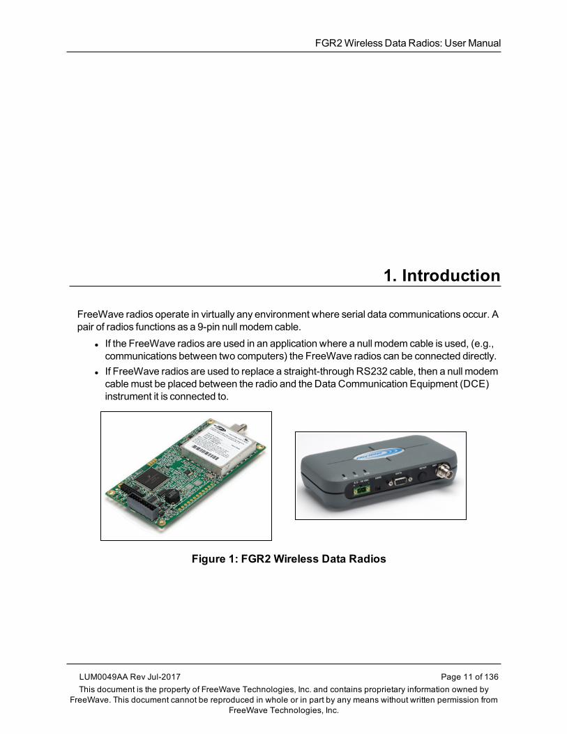
FreeWave radios operate in virtually any environment where serial data communications occur. Apair of radios functions as a 9-pin null modem cable.
l If the FreeWave radios are used in an application where a null modem cable is used, (e.g.,communications between two computers) the FreeWave radios can be connected directly.
l If FreeWave radios are used to replace a straight-through RS232 cable, then a null modemcablemust be placed between the radio and the Data Communication Equipment (DCE)instrument it is connected to.
Figure 1: FGR2 Wireless Data Radios
LUM0049AA Rev Jul-2017 Page 11 of 136This document is the property of FreeWave Technologies, Inc. and contains proprietary information owned by
FreeWave. This document cannot be reproduced in whole or in part by any means without written permission fromFreeWave Technologies, Inc.
1. Introduction
Page 12 of 136 LUM0049AA Rev Jul-2017This document is the property of FreeWave Technologies, Inc. and contains proprietary information owned by
FreeWave. This document cannot be reproduced in whole or in part by any means without written permission fromFreeWave Technologies, Inc.
1.1. Choose a Radio LocationPlacement of the FreeWave radiomay have a significant impact on its performance. The key tothe overall robustness of the radio link is the height of the antenna.When using an external antenna, placement of that antenna is critical to a solid data link. Otherantennas in close proximity are a potential source of interference.Use theRadio Statistics to help identify potential problems. In general, FreeWave units with ahigher antenna placement will have a better communication link.In practice, the radio should be placed away from computers, telephones, answeringmachines,and other similar devices. The cable included with the radio provides ample distance forplacement away from other equipment.
Note: FreeWave offers directional andOmni-directional antennas with cable lengths ranging from 3to 200 feet.
An adjustment as little as 2 feet in antenna placement may resolve noise issues.In extreme cases, (e.g., Cellular Telephone tower interference) the band pass filters thatFreeWave offers may reduce out-of-band noise.
In extreme cases, such aswhen interference is due to a Pager or Cellular Telephone tower, theband pass filters that FreeWave offers, may reduce this out-of-band noise.
1.2. Choosing Point-to-Point or Point-to-MultiPoint OperationImportant!: For either a PTP or PTMP network, adding a Repeater cuts the network throughput by50%.
1.2.1. Point-to-Point (PTP) NetworkA PTP network work best when the network consists of oneMaster and one Slave radio.
Note: A maximum of four Repeaters can be added to extend the reach of the network.
1.2.2. Point-to-MultiPoint (PTMP) NetworkIn a PTMP network (also referred to asMultiPoint network) theMaster radio is able tosimultaneously communicate with numerous Slave radios.
l AMultiPoint network functionswith theMaster broadcasting itsmessages to all Slaveradios.
l If requested by theMaster, the Slave radios respond to theMaster when given data by thedevice connected to the data port. The response depends on the setup.
l The network reach can be extended with asmanyRepeaters as is required.

FGR2WirelessData Radios: User Manual
Differences between PTP and PTMPl In a Point-to-Point network all packets are acknowledged, whether sent from theMaster tothe Slave or from the Slave to theMaster.
l In aMultiPoint network, the user determines the number of times outbound packets fromtheMaster or Repeater to the Slave or other Repeaters are sent.l The receiving radio, Slave or Repeater, accepts the first packet received that passes the32 bit CRC. However, the packet is NOT acknowledged.
l On the return trip to theMaster, all packets sent are acknowledged or retransmitted untilthey are acknowledged.
l Therefore, the return link in aMultiPoint network is generally very robust.Traditionally, a MultiPoint network is used in applicationswhere data is collected frommanyinstruments and reported back to one central site. The architecture of such a network is differentfromPoint-to-Point applications. These parameters influence the number of radios that can existin aMultiPoint network:
l Data block size.l The longer the data blocks, the fewer number of deployed Slave radios can exist in thenetwork.
l Baud rate.l The data rate between the radio and the device it is connected to could limit the amountof data and the number of radios that can exist in a network
l The amount of contention between Slave radios.l Polled Slave radios versus timed Slave radios.l Repeater Use.
l Using theRepeater setting in a Point-to-Point or MultiPoint network decreases overallnetwork capacity by 50%.
Example: If the network polls once a day to retrieve sparse data, several hundred Slave radios couldbe configured to a single Master.However, if each Slave transmits larger amounts of data or datamore frequently, fewer Slave radioscan link to theMaster while receiving the same network performance.When larger amounts of data are sent more frequently, the overall network bandwidth is closer tocapacity with fewer Slave radios.
LUM0049AA Rev Jul-2017 Page 13 of 136This document is the property of FreeWave Technologies, Inc. and contains proprietary information owned by
FreeWave. This document cannot be reproduced in whole or in part by any means without written permission fromFreeWave Technologies, Inc.

1. Introduction
Page 14 of 136 LUM0049AA Rev Jul-2017This document is the property of FreeWave Technologies, Inc. and contains proprietary information owned by
FreeWave. This document cannot be reproduced in whole or in part by any means without written permission fromFreeWave Technologies, Inc.
1.3. Data Communication Link Examplesl Example 1 - Point-to-Point Gateway to Endpoint (on page 14)l Example 2 - GatewayRepeater Endpoint (on page 14)l Example 3 - TwoRepeaters (on page 14)l Example 4 - Multiple Radios (on page 15)l Example 5 - Point-to-MultiPoint (on page 16)l Example 6 - Point-to-MultiPoint with a Repeater Site (on page 17)
1.3.1. Example 1 - Point-to-Point Gateway to EndpointThe versatility of FreeWave radios allows data links to be established using a variety of differentconfigurations.This example shows themost common and straight forward link; aMaster communicating to aSlave in a Point-to-Point link.
Figure 2: Master Communicating to a Slave in a Point-to-Point Link
1.3.2. Example 2 - Gateway Repeater EndpointThis example shows a link using a Repeater.
l TheRepeater may be located on a hilltop or other elevated structure enhancing the linkfrom theMaster to the Slave.
l In this configuration, it may be desirable to use an external Omni directional antenna at theRepeater.
l A Yagi antennamay be used at both theMaster and Slave radios.
Note: Adding Repeaters to a network cuts the network throughput by 50%.
Figure 3: Master Communicating to a Slave in a Point-to-Point Link with aRepeater
1.3.3. Example 3 - Two RepeatersThis example shows a link with two Repeaters between theMaster and Slave.
l With two Repeaters there ismore flexibility in getting around obstacles and greater totalrange is possible.
FGR2WirelessData Radios: User Manual
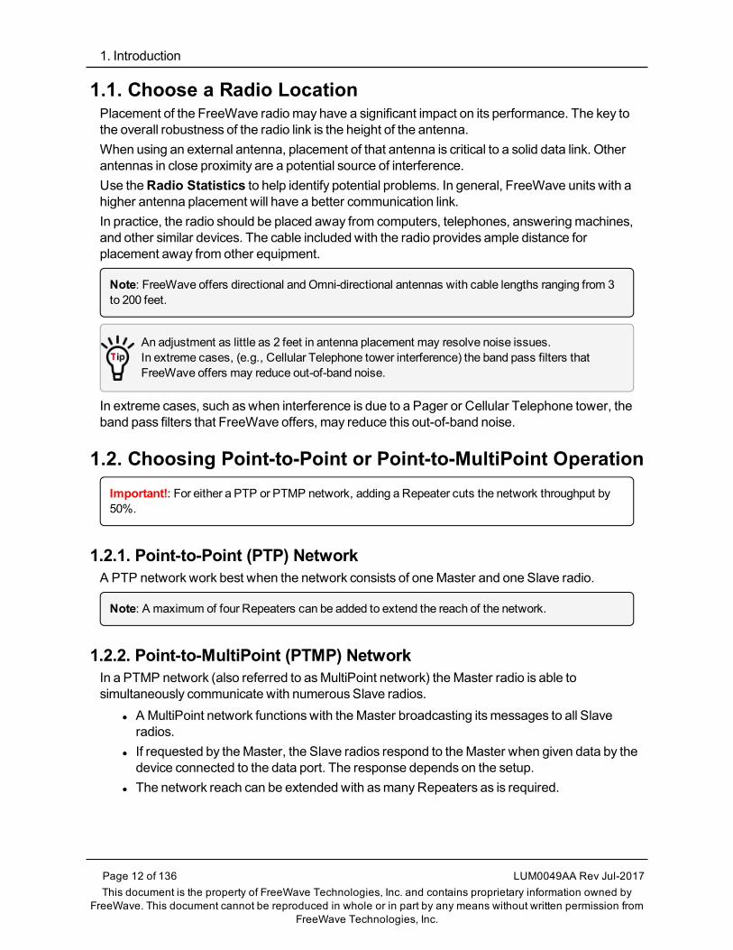
l It may be desirable to use external Omni-directional antennaswith the Repeaters, andattaching a Yagi antenna to theMaster and Slave radio to increase the range of the link.
l When twoRepeaters are used no further degradation in the RF throughput of the link isexperienced.
Figure 4: Master Communicating to a Slave in a Point-to-Point Link with TwoRepeaters
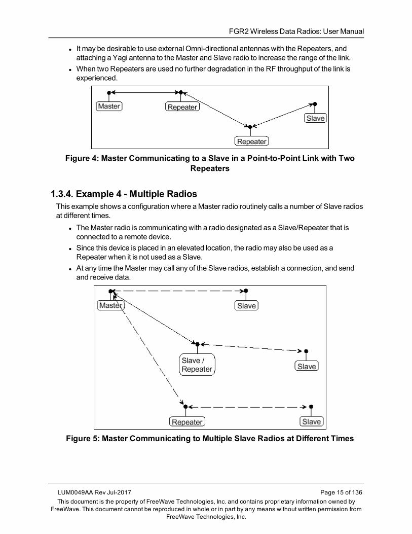
1.3.4. Example 4 - Multiple RadiosThis example shows a configuration where aMaster radio routinely calls a number of Slave radiosat different times.
l TheMaster radio is communicating with a radio designated as a Slave/Repeater that isconnected to a remote device.
l Since this device is placed in an elevated location, the radiomay also be used as aRepeater when it is not used as a Slave.
l At any time theMaster may call any of the Slave radios, establish a connection, and sendand receive data.
Figure 5: Master Communicating to Multiple Slave Radios at Different Times
LUM0049AA Rev Jul-2017 Page 15 of 136This document is the property of FreeWave Technologies, Inc. and contains proprietary information owned by
FreeWave. This document cannot be reproduced in whole or in part by any means without written permission fromFreeWave Technologies, Inc.

1. Introduction
Page 16 of 136 LUM0049AA Rev Jul-2017This document is the property of FreeWave Technologies, Inc. and contains proprietary information owned by
FreeWave. This document cannot be reproduced in whole or in part by any means without written permission fromFreeWave Technologies, Inc.
1.3.5. Example 5 - Point-to-MultiPointThis example illustrates a standard Point-to-MultiPoint network.
l From theMaster, any data is broadcast to all three Slave radios, one of which receives itthrough aMultipoint Repeater.
l The data is sent out of the serial port of each of the three Slave radios.l The end device should be configured to interpret the serial message and act on it ifnecessary.
Figure 6: Master Communicating in a Point-to-MultiPoint Network
FGR2WirelessData Radios: User Manual
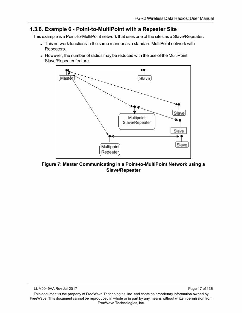
1.3.6. Example 6 - Point-to-MultiPoint with a Repeater SiteThis example is a Point-to-MultiPoint network that uses one of the sites as a Slave/Repeater.
l This network functions in the samemanner as a standardMultiPoint network withRepeaters.
l However, the number of radiosmay be reduced with the use of theMultiPointSlave/Repeater feature.
Figure 7: Master Communicating in a Point-to-MultiPoint Network using aSlave/Repeater
LUM0049AA Rev Jul-2017 Page 17 of 136This document is the property of FreeWave Technologies, Inc. and contains proprietary information owned by
FreeWave. This document cannot be reproduced in whole or in part by any means without written permission fromFreeWave Technologies, Inc.

1. Introduction
Page 18 of 136 LUM0049AA Rev Jul-2017This document is the property of FreeWave Technologies, Inc. and contains proprietary information owned by
FreeWave. This document cannot be reproduced in whole or in part by any means without written permission fromFreeWave Technologies, Inc.
1.4. Finding the Product Serial NumberEach FreeWave radio is assigned a unique serial number.
Important!: This number is needed to contact FreeWave Technical Support.
The serial number is three digits, followed by a hyphen, then four digits (e.g., 111-1111), and isprinted on the FreeWave label on the radio.
Note: The example in this section is an image is of a GXMmodel.The serial number information is in the same location on different models.
Figure 8: Example of the Serial Number for a GXMmodel
On radios that are not in an enclosure, the serial number is printed on a label on the back (the flat,smooth side) of the radio.This label is in larger print.
Figure 9: Example of the label and Serial Number of a non-enclosed radio
FGR2WirelessData Radios: User Manual
1.5. Powering the RadioConnect the radio to a positive power supply with +6.0 to +30.0 VDC, typically +12.0 VDC.
Important!: FGR2 radios are UL approved for use between +6.0 to +30.0 VDC.
FREEWAVE Recommends: For guaranteed performance, FreeWave recommends using between+7.5 to +30.0 VDC to power the radio.
Warning! If the power supply is above approximately +18.0 to +20.0 VDC, use a 1-ohmresistor inline with B+ input to the radio.For more information about pinouts, see RF Board Level Pinout (on page 110).
If the power supply line runs outside the enclosure, use:l electrostatic discharge (ESD) protectors to protect the radio from electric shock.l transient voltage suppressors (TVS) to protect from an over-voltage situation.
Using both helps enhances reliable operation.
1.6. Configuration Tool OptionsWhen the radio is inSetupmode, use these setup tools to configure the settings on the radio:
l Tool Suite- Tool Suite is the recommendedmethod for programming the radios.l It provides a group of tools for configuring the devices in the network and for monitoringthe network's performance.
l Use theConfiguration application in Tool Suite to program changes to the radio'ssettings.
l Tool Suite is available for download fromwww.freewave.com.
Note: For more information about using Tool Suite, see the Tool Suite User Manual in theTool Suite software.
l Terminal Emulator - A terminal emulator program (e.g., HyperTerminal or Tera Term)offersmany of the same configuration options available in theConfiguration application inTool Suite.l If running versions of theWindows® operating system prior toWindows® 7,HyperTerminal is included in the operating system installation.
Use theSetup Terminal application in Tool Suite to use and view the terminal menus.It shows the samemenus and provides the same programming settings as you see using aterminal emulator.
LUM0049AA Rev Jul-2017 Page 19 of 136This document is the property of FreeWave Technologies, Inc. and contains proprietary information owned by
FreeWave. This document cannot be reproduced in whole or in part by any means without written permission fromFreeWave Technologies, Inc.

1. Introduction
Page 20 of 136 LUM0049AA Rev Jul-2017This document is the property of FreeWave Technologies, Inc. and contains proprietary information owned by
FreeWave. This document cannot be reproduced in whole or in part by any means without written permission fromFreeWave Technologies, Inc.
FREEWAVE Recommends: Tool Suite is the recommended programming option. EZConfig canstill be used to program older radio models. However, newer radio models and newer firmwareversions are not available in EZConfig.
1.6.1. Tool Suite and Terminal EmulatorsIf using a terminal emulator, the tabs for a device in Tool Suite mirror theSetupmainmenuselections.
Example: Option 0 on theSetupmainmenu in the terminal menu setup is Set Operation Mode.The corresponding configuration tab for the device in Tool Suite is (0) Operation Mode.
Figure 10: Tool Suite menu Matched to Terminal menu
Use theSetup Terminal application in Tool Suite to use and view the terminal menus.It shows the samemenus and provides the same programming settings as you see using aterminal emulator.
Note: In this document, if the setup procedure in the terminal emulator is different than the procedurein Tool Suite, the terminal instructions are also included.
1.7. Radio Setup ModeTo read the current settings from or to program a radio, the radiomust be inSetupmode.When aradio is inSetupmode, all three LEDs appear solid green . These sections provide detailsabout how to access the radio'sSetupmode using Tool Suite or the terminal interface.
Note: OEM boards may also enterSetupwhen Pin 2 on a 10- or 14-pin connector or Pin 8 on a 24-pinconnector is grounded, or using a break command.For information about the break command, see Use Break to Access Setup (on page 38).

FGR2WirelessData Radios: User Manual
l TheSetup Port parameter on theBaud Rate tab determineswhether themain data portor the diagnostics port is used to access the setup parameters for the radio. For moreinformation, see Setup Port (on page 36).
l Use theSetup Mode Timeout parameter on theOperation Mode tab to set the radio toexit Setup Mode automatically. When the setting is enabled, if the radio has not receivedanymenu selections or programming information within 5 seconds, it exitsSetup andresumes its previousmode.
Note: ForSetupmode troubleshooting information, see Troubleshooting (on page 114).
1.7.1. Using Tool Suite to Connect to and Program RadiosTo read and program a radio using Tool Suite, connect the radio to a computer that runs the ToolSuite software.
Use Tool Suite to set up a template version of a radio. Templates include settings that apply tomore than one radio in the network.
Note: For more information about using templates, see the Tool SuiteUser Manual in the Tool Suitesoftware.
Procedure1. Connect a serial or diagnostic cable between the computer and the radio.
FREEWAVE Recommends: Using a diagnostic cable and the diagnostic port.
2. Connect the power supply to the radio and the power source and turn on the radio.3. Open Tool Suite.4. In theApplicationswindow, clickConfiguration to open theConfiguration application.5. Verify the correct port is selected in theCom Port field on theConfiguration ribbon.6. Press theSetup button on the back of the FreeWave radio.
The radio is changed toSetupmode.
Note: If connected to the diagnostics port, the radio changes toSetup mode automaticallywhenRead Radio is clicked in Tool Suite.
7. Short Pins 2 and 4 (Brown to Black) on the 10-pin header next to the LEDs.This places a board-level radio intoSetup mode.
8. If using a data cable (FreeWave part number:ASC3610DB orASC3610DJ), press theSetup button on the data cable.
Note: If using theSetup Terminal application or a terminal emulator and using the grayribbon diagnostic cable (part numberAC2009DC), or the black diagnostic cable (part numberASC0409DC), the radio changes toSetup mode automatically whenRead Radio is clickedin Tool Suite.
LUM0049AA Rev Jul-2017 Page 21 of 136This document is the property of FreeWave Technologies, Inc. and contains proprietary information owned by
FreeWave. This document cannot be reproduced in whole or in part by any means without written permission fromFreeWave Technologies, Inc.

1. Introduction
Page 22 of 136 LUM0049AA Rev Jul-2017This document is the property of FreeWave Technologies, Inc. and contains proprietary information owned by
FreeWave. This document cannot be reproduced in whole or in part by any means without written permission fromFreeWave Technologies, Inc.
All three LEDs on the radio are green and stay green as long as the radio is inSetupmode.
9. On theConfiguration ribbon, clickRead Radio to read the radio's current settings.10. Make the necessary parameter changes.11. On theNetwork Title ribbon, use one of these options to send the changes to the radio:
l ClickQuick to send only the changed parameters.
Note: This option is only available if Read Radio is clicked and parameter settings areNOT sent from a template to the radio.
l ClickAll to send all the settings for all parameters.l ClickDefault to set a device back to its factory default settings.
Figure 11: FGR2 Setup Port
Figure 12: FGR2 Pin Layout
Note: For more information about using Tool Suite, see the Tool Suite User Manual in the ToolSuite software.

FGR2WirelessData Radios: User Manual
1.7.2. Access the Setup Menu Using a Terminal EmulatorThis procedure accesses the radio'sSetupmenu using theSetup Terminal application in ToolSuite.
Note: For more information about using Tool Suite, see the Tool Suite User Manual in the ToolSuite software.
Procedure1. Plug a serial cable into the COM1 port on the radio.2. Connect the cable to a COMport on the computer running Tool Suite.3. Connect the radio to a power source.4. Open Tool Suite.5. On theApplicationswindow, clickSetup Terminal.6. Click theConnection list box arrow in the top left of the window and select the COMport
on the computer the radio is connected to.
Figure 13: Connection list box
7. ClickConnect.8. To connectSetup Terminal to the radio, press theSetup button on the back of the
FreeWave radio.If connected to the diagnostics port, press <Shift+U> to view theSetupmenu.
Figure 14: FGR2 Setup Port
LUM0049AA Rev Jul-2017 Page 23 of 136This document is the property of FreeWave Technologies, Inc. and contains proprietary information owned by
FreeWave. This document cannot be reproduced in whole or in part by any means without written permission fromFreeWave Technologies, Inc.

1. Introduction
Page 24 of 136 LUM0049AA Rev Jul-2017This document is the property of FreeWave Technologies, Inc. and contains proprietary information owned by
FreeWave. This document cannot be reproduced in whole or in part by any means without written permission fromFreeWave Technologies, Inc.
9. To view theSetupmenu in board-level radios:l Short pins 2 & 4 (Brown to Black) on the 10 pin header next to the LEDs.
Figure 15: FGR2 Pin Layout
l If using a data cable (FreeWave part number:ASC3610DB orASC3610DJ), press theSetup button on the data cable.
l If using the gray ribbon diagnostic cable (P/N AC2009DC), or the black diagnosticcable (P/N ASC0409DC), press <Shift+U> to view theSetupmenu.
WhenSetup is activated, the FreeWaveSetup Main Menu appears in the HyperTerminaldialog box.All three LEDs on the radio are green and stay green as long as the radio is inSetupmode.
Important!: When navigating through the Setupmenu andmaking changes to the parameters, theparameters are sent immediately to the radio.
1.7.3. Connecting and Disconnecting from HyperTerminalTheHyperTerminal dialog box has several toolbar buttons.To reconnect to HyperTerminal, disconnect from the current session.
1. Click theDisconnect .
2. Click theCall to reconnect.
Note: If the settings have not been saved they must be re-selected when HyperTerminal reconnectsto the radio.
FGR2WirelessData Radios: User Manual
1.7.4. Troubleshooting HyperTerminalThese are some common issues encountered while using HyperTerminal as the terminalemulator.
l The steps to resolve the issue are specific to the HyperTerminal interface.l Similar steps can be used when troubleshooting other terminal emulators.
Important!: When a change is made to the HyperTerminal settings in an open terminal session, theconnectionmust be disconnected then reconnected before the settings take effect.
l Change the COMPort (on page 25).l Change the Baud Rate (on page 26).l Change the Flow Control (on page 26).l Change the Parity (on page 27).
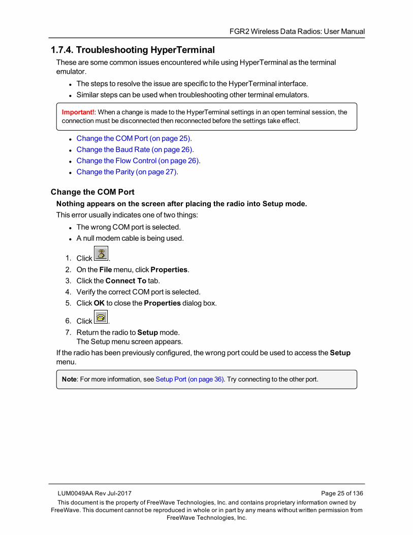
Change the COM PortNothing appears on the screen after placing the radio into Setup mode.This error usually indicates one of two things:
l Thewrong COMport is selected.l A null modem cable is being used.
1. Click .2. On the Filemenu, clickProperties.3. Click theConnect To tab.4. Verify the correct COMport is selected.5. ClickOK to close theProperties dialog box.
6. Click .7. Return the radio toSetupmode.
The Setupmenu screen appears.If the radio has been previously configured, the wrong port could be used to access theSetupmenu.
Note: For more information, see Setup Port (on page 36). Try connecting to the other port.
LUM0049AA Rev Jul-2017 Page 25 of 136This document is the property of FreeWave Technologies, Inc. and contains proprietary information owned by
FreeWave. This document cannot be reproduced in whole or in part by any means without written permission fromFreeWave Technologies, Inc.
1. Introduction
Page 26 of 136 LUM0049AA Rev Jul-2017This document is the property of FreeWave Technologies, Inc. and contains proprietary information owned by
FreeWave. This document cannot be reproduced in whole or in part by any means without written permission fromFreeWave Technologies, Inc.
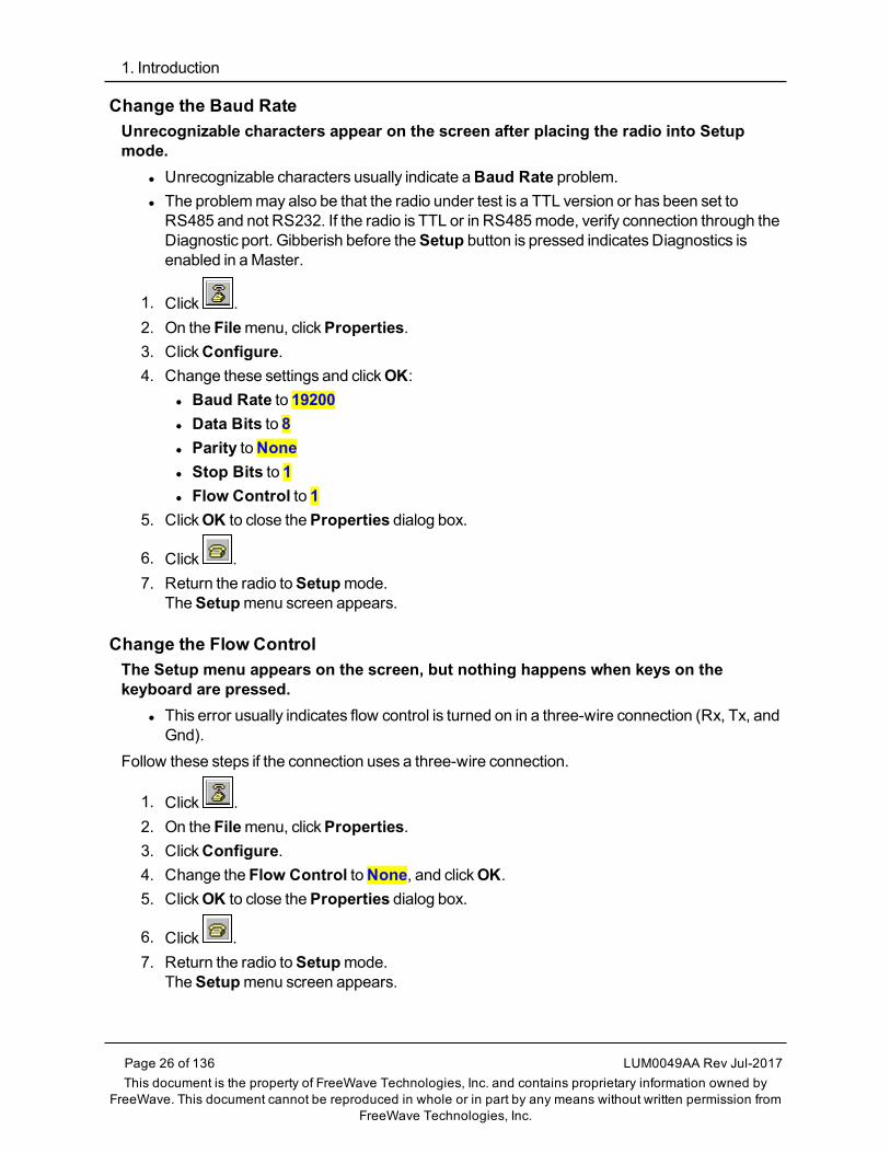
Change the Baud RateUnrecognizable characters appear on the screen after placing the radio into Setupmode.
l Unrecognizable characters usually indicate aBaud Rate problem.l The problemmay also be that the radio under test is a TTL version or has been set toRS485 and not RS232. If the radio is TTL or in RS485mode, verify connection through theDiagnostic port. Gibberish before theSetup button is pressed indicatesDiagnostics isenabled in aMaster.
1. Click .2. On the Filemenu, clickProperties.3. ClickConfigure.4. Change these settings and clickOK:
l Baud Rate to 19200l Data Bits to 8l Parity toNonel Stop Bits to 1l Flow Control to 1
5. ClickOK to close theProperties dialog box.
6. Click .7. Return the radio toSetupmode.
TheSetupmenu screen appears.
Change the Flow ControlThe Setup menu appears on the screen, but nothing happens when keys on thekeyboard are pressed.
l This error usually indicates flow control is turned on in a three-wire connection (Rx, Tx, andGnd).
Follow these steps if the connection uses a three-wire connection.
1. Click .2. On the Filemenu, clickProperties.3. ClickConfigure.4. Change the Flow Control toNone, and clickOK.5. ClickOK to close theProperties dialog box.
6. Click .7. Return the radio toSetupmode.
TheSetupmenu screen appears.
FGR2WirelessData Radios: User Manual
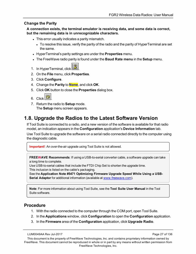
Change the ParityA connection exists, the terminal emulator is receiving data, and some data is correct,but the remaining data is in unrecognizable characters.
l This error usually indicates a paritymismatch.l To resolve this issue, verify the parity of the radio and the parity of HyperTerminal are setthe same.
l HyperTerminal’s parity settings are under thePropertiesmenu.l The FreeWave radio parity is found under theBaud Rate menu in theSetupmenu.
1. In HyperTerminal, click .2. On the Filemenu, clickProperties.3. ClickConfigure.4. Change theParity toNone, and clickOK.5. ClickOK button to close theProperties dialog box.
6. Click .7. Return the radio toSetupmode.
TheSetupmenu screen appears.
1.8. Upgrade the Radios to the Latest Software VersionIf Tool Suite is connected to a radio, and a new version of the software is available for that radiomodel, an indication appears in theConfiguration application'sDevice Information tab.Use Tool Suite to upgrade the software on a serial radio connected directly to the computer usingthe diagnostic cable.
Important!: An over-the-air upgrade using Tool Suite is not allowed.
FREEWAVE Recommends: If using a USB-to-serial converter cable, a software upgrade can takea long time to complete.Use USB-to-serial cables that include the FTDI Chip Set to shorten the upgrade time.This inclusion is listed on the cable's packaging.See theApplication Note #5471 Optimizing Firmware Upgrade Speed While Using a USB-Serial Adaptor for additional information (available at www.freewave.com).
Note: For more information about using Tool Suite, see the Tool Suite User Manual in the ToolSuite software.
Procedure1. With the radio connected to the computer through the COMport, open Tool Suite.2. In theApplicationswindow, clickConfiguration to open theConfiguration application.3. In the Firmware area of theConfiguration application, clickUpgrade Radio.
LUM0049AA Rev Jul-2017 Page 27 of 136This document is the property of FreeWave Technologies, Inc. and contains proprietary information owned by
FreeWave. This document cannot be reproduced in whole or in part by any means without written permission fromFreeWave Technologies, Inc.
1. Introduction
Page 28 of 136 LUM0049AA Rev Jul-2017This document is the property of FreeWave Technologies, Inc. and contains proprietary information owned by
FreeWave. This document cannot be reproduced in whole or in part by any means without written permission fromFreeWave Technologies, Inc.
4. ClickYes at the prompt to proceed.Tool Suite identifies the software version loaded on the connected device and shows thelatest version of software available for that model.
5. ClickYes to continue with the upgrade.The system shows the progress of the software upgrade.After the firmware upgrade is complete, amessage appears confirming that the softwareupgrade was successful.

FGR2WirelessData Radios: User Manual
2. Basic RadioProgramming and Setup
When setting up either a Point-to-MultiPoint network or a Point-to-Point network, the process forsetting up and programming a radio is the same.This section describes these aspects of programming and setting up a radio:
l Setting the Radio's Role in the Network and the Network Type (on page 30).l Establishing Communication with Instrumentation and Computers (on page 33).l Establishing Communication with Other Radios in the Network (on page 39).l Designate the RF Transmission Characteristics (on page 40).
LUM0049AA Rev Jul-2017 Page 29 of 136This document is the property of FreeWave Technologies, Inc. and contains proprietary information owned by
FreeWave. This document cannot be reproduced in whole or in part by any means without written permission fromFreeWave Technologies, Inc.
2. Basic Radio Programming and Setup
Page 30 of 136 LUM0049AA Rev Jul-2017This document is the property of FreeWave Technologies, Inc. and contains proprietary information owned by
FreeWave. This document cannot be reproduced in whole or in part by any means without written permission fromFreeWave Technologies, Inc.
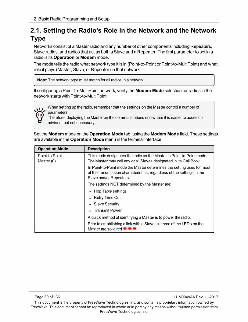
2.1. Setting the Radio's Role in the Network and the NetworkTypeNetworks consist of aMaster radio and any number of other components including Repeaters,Slave radios, and radios that act as both a Slave and a Repeater. The first parameter to set in aradio is itsOperation orModemmode.Themode tells the radio what network type it is in (Point-to-Point or Point-to-MultiPoint) and whatrole it plays (Master, Slave, or Repeater) in that network.
Note: The network typemust match for all radios in a network.
If configuring a Point-to-MultiPoint network, verify theModem Mode selection for radios in thenetwork starts with Point-to-MultiPoint.
When setting up the radio, remember that the settings on theMaster control a number ofparameters.Therefore, deploying theMaster on the communications end where it is easier to access isadvised, but not necessary.
Set theModemmode on theOperation Mode tab, using theModem Mode field. These settingsare available in theOperation Modemenu in the terminal interface.
Operation Mode DescriptionPoint-to-PointMaster (0)
This mode designates the radio as theMaster in Point-to-Point mode.TheMaster may call any or all Slaves designated in its Call Book.In Point-to-Point mode theMaster determines the setting used for mostof the transmission characteristics, regardless of the settings in theSlave and/or Repeaters.The settings NOT determined by theMaster are:
l Hop Table settingsl Retry TimeOutl Slave Securityl Transmit Power
A quick method of identifying aMaster is to power the radio.Prior to establishing a link with a Slave, all three of the LEDs on theMaster are solid red .

FGR2WirelessData Radios: User Manual
Operation Mode DescriptionPoint-to-PointSlave (1)
This mode designates the radio as a Slave in Point-to-Point mode.
l The Slave communicates with any Master in its Call Book - eitherdirectly or through amaximum of four Repeaters.
l When functioning as a Slave, the Entry to Call feature in the radio’sCall Book is NOT operational.
l Set theSlave Security parameter to 1 to bypass the Call Book in theSlave.
Note: For more information, see Slave Security on page 56.
Point–to-MultiPointMaster (2)
This mode designates the radio as aMaster in MultiPoint mode.
l This mode allows oneMaster radio to communicate simultaneouslywith numerous Slaves and Repeaters.
l A Point-to-MultiPoint Master communicates only with other radiosdesignated as Point-to-MultiPoint Slaves or Point-to-MultiPointRepeaters.
Point-to-MultiPointSlave (3)
This mode designates the radio as a Slave inMultiPoint mode.
l This mode allows the Slave to communicate with aMultiPointMaster.
l The Slavemay communicate with its Master through one or moreRepeaters.
Point-to-Point Slave /Repeater (4)
This mode designates the radio to act as either a Slave or Repeater,depending on the instructions from theMaster.
l The radio cannot act as both a Slave and a Repeater at the sametime.
l True Slave/Repeater functionality is only available in aMultiPointmode.
l Point-to-Point Slave/Repeaters have no security features.l When a radio is designated a Point-to-Point Slave/Repeater, itallows any Master to use it as a Repeater.
Note: Adding Repeaters to a network cuts the networkthroughput by 50%.
LUM0049AA Rev Jul-2017 Page 31 of 136This document is the property of FreeWave Technologies, Inc. and contains proprietary information owned by
FreeWave. This document cannot be reproduced in whole or in part by any means without written permission fromFreeWave Technologies, Inc.

2. Basic Radio Programming and Setup
Page 32 of 136 LUM0049AA Rev Jul-2017This document is the property of FreeWave Technologies, Inc. and contains proprietary information owned by
FreeWave. This document cannot be reproduced in whole or in part by any means without written permission fromFreeWave Technologies, Inc.
Operation Mode DescriptionPoint-to-PointRepeater (5)
FreeWave allows the use of amaximum of four Repeaters in a Point-to-Point communications link, significantly extending the operating range.
l When designated as a Repeater, a radio behaves as a pass-throughlink.
l All settings for the Call Book, baud rates, and transmissioncharacteristics are disabled.
l A Repeater connects with any Master that calls it.l The Repeater must be set up properly in theMaster's Call Book.
Note: Adding Repeaters to a network cuts the networkthroughput by 50%.
Point-to-Point Slave /Master Switchable (6)
Mode 6 allows the radio to be controlled entirely through softwarecommands.
l A number of key parameters in the FreeWave user interfacemay bechanged either directly using a terminal emulator or using script files.
l When thePoint-to-Point Slave/Master Switchable option isselected and the radio is not calling a Slave, it functions as a Slaveand accepts any appropriate calls from other radios.
Note: For more information, seeApplication Note #5476, Mode6.
Point-to-MultiPointRepeater (7)
This option allows the radio to operate as a Repeater in aMultiPointnetwork.
l A MultiPoint network can have as many Repeaters as necessary.l If the Repeater is to act as a Slave/Repeater, set theSlaveRepeater parameter in theMultiPoint Parameters tab toEnabled.
Note: Adding Repeaters to a network cuts the networkthroughput by 50%.
Mirrorbit Master (A)Mirrorbit Slave (B)
Mirrored Bit Communication is supported in firmware version 8.77 andlater.For information aboutMirrored Bit Communication, see theFreeWave:
l Application Note #5424, Using the FGR-115MB Radio withSchweitzer Engineering Labs Mirrored Bits Communications.
l FGR RadioModem inMirrored Bit Mode Addendum.
Ethernet Options (F) This menu is used for Ethernet radios only.

FGR2WirelessData Radios: User Manual
2.2. Establishing Communication with Instrumentation andComputersThe settings on theBaud Rate tab are the communications settings between the radio and theinstrument or computer it is connected to (radio serial port to the device).
Important!: These settings are unique to each radio, and do not need tomatch across the network.
Example: A pair of radios may be used in an application to send data from remote processinstrumentation to an engineer's computer.In this application, theBaud Rate for the radio on the instrumentationmight be set to 9600 and theradio on the polling host might be set to 57,600.
These settings are available in theBaud Ratemenu in the terminal interface, and apply to bothPoint-to-Point and Point-to-MultiPoint networks.
Note: See the Parameter Preference (on page 10) for a description of the parameter table's content.
2.2.1. Baud RateBaud RateSetting DescriptionDefault Setting: 115200
Options: 600, 1200, 2400, 4800, 9600, 19200, 38400, 57600, 76800, 115200, 230400
Terminal Menu: (1) Set Baud Rate
Description: l This is the communication rate between the radio's data port and theinstrument it is connected to.
l This setting is independent from the baud rate for the other radios in thenetwork.
Note: With a poor RF link, this may actually result in slower datacommunications.
l TheSetup PortBaud Rate always defaults to 19,200 nomatter how theDataPortBaud Rate is set.l The only exception is Mode 6.
l Formore information, seeApplication Note #5476, Mode 6.
FREEWAVE Recommends: With aBaud Rate setting of 38,400 orhigher, FreeWave recommends using the lines of the Flow Control (onpage 34).
LUM0049AA Rev Jul-2017 Page 33 of 136This document is the property of FreeWave Technologies, Inc. and contains proprietary information owned by
FreeWave. This document cannot be reproduced in whole or in part by any means without written permission fromFreeWave Technologies, Inc.

2. Basic Radio Programming and Setup
Page 34 of 136 LUM0049AA Rev Jul-2017This document is the property of FreeWave Technologies, Inc. and contains proprietary information owned by
FreeWave. This document cannot be reproduced in whole or in part by any means without written permission fromFreeWave Technologies, Inc.
2.2.2. Data ParityData ParitySetting DescriptionDefault Setting: 0 (8, N, 1)
Options: See Description.
Terminal Menu: (1) Set Baud Rate > (A) Data Parity
Description: l Six data word length and parity configurations are available for use withFreeWave radios.
l The default setting is 8-None-1 and is themost commonly used serialcommunications protocol.
This table describes each option:
Option Data Bits Parity Stop Bits0 8 None 1
1 7 Even 1
2 7 Odd 1
3 8 None 2
4 8 Even 1
5 8 Odd 1
2.2.3. Flow ControlFlow ControlSetting DescriptionDefault Setting: (0) None
Options: l (0) None - No flow control CTS is active and de-asserts when buffering is 98%full. Can pass XON/XOFF data but does not use it in any way.
l (1) RTS - Uses RTS/CTS (Request to Send/Clear to Send) for flow control.l CTS performs the sameway as in option 0 (none).l RTS must be activated for the radio to output data over the serial port.
l (2) DTR - Uses DTR/DSR (Data Terminal Ready/Data Set Ready) for flowcontrol.
l (3) DOT - Half Duplex.Terminal Menu: (1) Set Baud Rate > (F) FlowControl
Description: Specifies the hardware flow control for the data port on the radio.Flow control is the process of managing the speed data is transmitted to notoverwhelm the device receiving the transmission.
FREEWAVE Recommends: Use Flow Control if theBaud Rate ishigher than 38,400.

FGR2WirelessData Radios: User Manual
2.2.4. Modbus RTU
Note: When using the radio inModbus RTU mode, theMaster Packet Repeat parameter setting ontheMultiPoint Parameters tabMUSTmatch in every radio.TheModbus RTU modemust be set to 1when radios are configured in RS485 or RS422mode.
Modbus RTUSetting DescriptionDefault Setting: 0 (Disabled)
Options: 0 to 9
Terminal Menu: (1) Set Baud Rate > (B) Modbus RTU
Description: A setting other than 0 in this parameter causes the radio to wait for an amount oftime gathering data before sending out the RF link.
l 0 (Disabled) - The radio sends data out through its RF link as soon as the datais received into the serial port. This is the default setting.
l 1 - The radio waits for a number of slots equal to two times theMaster PacketRepeat setting before sending the received data out the RF link.
Example: If theMaster Packet Repeat parameter is set to 3, the radiowaits for 6 slots, gathering data up the whole time.At the end of the 6 slots, the radio sends all received data in one “burst.”This is the appropriate setting for most Modbus RTU devices.
l 2 or higher - The radio waits for a number of slots calculated using thisformula:(Modbus RTU setting + Master Packet Repeat setting + 1) x 2
Example: In a radio where theModbus RTU setting is 2 and theMasterPacket Repeat setting is 3, the radio waits for (2 + 3 + 1) x 2, or 12 slots.
LUM0049AA Rev Jul-2017 Page 35 of 136This document is the property of FreeWave Technologies, Inc. and contains proprietary information owned by
FreeWave. This document cannot be reproduced in whole or in part by any means without written permission fromFreeWave Technologies, Inc.

2. Basic Radio Programming and Setup
Page 36 of 136 LUM0049AA Rev Jul-2017This document is the property of FreeWave Technologies, Inc. and contains proprietary information owned by
FreeWave. This document cannot be reproduced in whole or in part by any means without written permission fromFreeWave Technologies, Inc.
2.2.5. Serial InterfaceSerial InterfaceSetting DescriptionDefault Setting: (0) RS232
Options: l (0) RS232 - Also used for TTL.l (1) RS422/Full Duplex RS485 -Modbus RTU modemust be enabled andTurn Off Delay set to at least 4.
l (2) Half Duplex RS485 -Modbus RTU modemust be enabled and Turn OffDelay set to at least 4.
l (3) DOT - DOT causes the CD line to indicate when data is transmitted on theserial port from the radio.l When the radio is not sending data to the serial port, CD is de-asserted.l When the radio is sending data to the serial port, CD is asserted.l The CD line no longer has any link state functionality.l Turn Off Delayworks as described in all radios.l Turn On Delayworks as described on any Slave or Slave/Repeater - it hasno functionality on theMaster.
If set to anything other than 0, theSetup Port parameter in theBaud Rate tabmust be set toDiagnostics Only.
Terminal Menu: (1) Set Baud Rate > (C) RS232/485
Description: Use this option to set the protocol of the data port for connection to an externaldevice.
Note: This settingmust be 0 in TTL RF board products.
2.2.6. Setup Port
Important!: Do NOT change this setting unless the correct programming cable is available for thenew setting.
Setup PortSetting DescriptionDefault Setting: (3) Both
The factory setting is based on the radio type.
l A setting of 2 is used with Ethernet products andMirrored Bit products.l A setting of 3 is used in other products.

FGR2WirelessData Radios: User Manual
Setup PortSetting DescriptionOptions: l (1) Main Only - Programming and reading a radio's setup information is done
through the data port.l (2) Diagnostics Only - Programming and reading a radio's setup informationis done through the diagnostic port.l If theSerial interface is set to anything other than RS232, then theSetupPortmust be set toDiagnostics Only.
l (3) Both - Programming and reading a radio's setup information is donethrough either the data port or the diagnostic port .
Terminal Menu: (1) Set Baud Rate > (D) Setup Port
Description: Determines which port on the radio, Main or Diagnostics, is used to access theparameter settings in Tool Suite or enter theSetupmainmenu in the terminalinterface.
l Themain data port is the RS232 port.l The diagnostics port is a 3-pin connector on the rear panel of the OEMMiniseries radios.l The diagnostic cable for this port (ASC0409DC) is available fromFreeWave.
l TheOEMmodules use a 2-row, 2mm female connector.l The diagnostic cable for this port (ASC2009DC) is available fromFreeWave.
2.2.7. Turn Off DelayTurn Off DelaySetting DescriptionDefault Setting: 0
Options: Any number between 0 and 9ms.
Terminal Menu: (1) Edit Baud Rate > Turn Off Delay
Description: Specifies the time after the end of transmission of a character to the RS485 busthat the radio stops driving the bus and releases the bus to other devices.
l The units are¼ of a character with a range of 0-9.l An entry of 4means a delay equivalent to the duration of a full character.l The default is 0 (zero) delay.l For data rates of 1200 bits/S or slower, avoid setting the Turn Off Delayparameter higher than 4.l At those rates the functionality of themicroprocessor changes so that aTurn Off Delay of 5 has the same effect as if set to 1, and a setting of 6 hasthe same effect as 2, and so on.
l Turn Off Delaymust be set to a value of at least 4 for RS422 and RS485operation.
LUM0049AA Rev Jul-2017 Page 37 of 136This document is the property of FreeWave Technologies, Inc. and contains proprietary information owned by
FreeWave. This document cannot be reproduced in whole or in part by any means without written permission fromFreeWave Technologies, Inc.

2. Basic Radio Programming and Setup
Page 38 of 136 LUM0049AA Rev Jul-2017This document is the property of FreeWave Technologies, Inc. and contains proprietary information owned by
FreeWave. This document cannot be reproduced in whole or in part by any means without written permission fromFreeWave Technologies, Inc.
2.2.8. Turn On DelayTurn On DelaySetting DescriptionDefault Setting: 0ms
Options: Any number between 0 and 9ms
Terminal Menu: (1) Set Baud Rate > (E) Turn OnDelay
Description: Sets the delay between when the line drivers are turned on and when the dataleaves the data port.
2.2.9. Use Break to Access Setup
Note: This setting is typically only used in OEM scenarios.
Use Break to Access SetupSetting DescriptionDefault Setting: Disabled
Options: l (0) - Disabled - The break command is disabled.l (1) - Enabled - The Setupmenu is sent at 19,200 bps.l (2) - Enabled - The Setupmenu is sent at the radio's current baud rate.
Terminal Menu: (1) Set Baud Rate > (G) Use break to access setup
Description: Enables a break command to put the radio into Setupmode over the data port.To send a break character, the end devicemust hold the Tx data line in the spacevoltage level for longer than 1 character time.
Example: If a character is defined as having 1 start bit, 8 data bits, and 1stop bit, the character time is 10 bits.Thus, the transmit data linemust be held in the space voltage level for aperiod of time longer than 10 bits.
FGR2WirelessData Radios: User Manual
2.3. Establishing Communication with Other Radios in theNetworkFor the radios in the network to communicate successfully, the radios need to be told what otherdevices are available for them to communicate with. Use one of these options:
l Network ID - Used inMultiPoint Networks, theNetwork ID parameter is available on theMultiPoint Parameters tab.l Each radio in a single network should be assigned the same ID.l A Slave links with the first Master or Repeater that it hears that has amatchingNetworkID.l Because theNetwork ID does not use serial numbers, MultiPoint Masters andRepeatersmay be replaced without reprogramming all of the Slaves in the network.TheNetwork ID function should be used in conjunction with theSubnet ID feature (ifnecessary) to route data through the radio network.
l Without having the serial numbers in the Call Book, Slavesmay establishcommunicationswith different Masters that match the radio's golden settingsdescribed below, though not at the same time. This is very useful in mobile MultiPointapplications.
l For information about setting theNetwork ID parameter in aMultiPoint Network, seeUsing the Network ID inMultiPoint Networks (on page 65).
l Call Book - The Call Book is required in Point-to-Point networks.l TheCall Book stores serial numbers of other radios in the network that are allowed to talkto a radio.
l Using the Call Book offers both security and flexibility in determining how FreeWaveradios communicate with each other.
FREEWAVE Recommends: While the Call Book is an option in Point-to-MultiPoint networks,FreeWave strongly recommends using theNetwork ID feature in most applications.If a largeMultiPoint network is implemented using the Call Book and a radio needs to be added to orreplaced in the network, each radio in the network must be physically reprogrammed and the newserial number entered in the radio's Call Book.This can be a time consuming process and can cause a delay in getting the network back up andrunning.Because theNetwork ID does not use serial numbers, MultiPoint Master radios and Repeaters maybe added or replaced without reprogramming each Slave radio in the network.
Note: For more information about defining the Call Book in a Point-to-Point network, see Using theCall Book in Point-to-Point Networks (on page 89).
LUM0049AA Rev Jul-2017 Page 39 of 136This document is the property of FreeWave Technologies, Inc. and contains proprietary information owned by
FreeWave. This document cannot be reproduced in whole or in part by any means without written permission fromFreeWave Technologies, Inc.
2. Basic Radio Programming and Setup
Page 40 of 136 LUM0049AA Rev Jul-2017This document is the property of FreeWave Technologies, Inc. and contains proprietary information owned by
FreeWave. This document cannot be reproduced in whole or in part by any means without written permission fromFreeWave Technologies, Inc.
2.3.1. Golden SettingsA standard network requires that these parameters are set the same on all radios in the network.FreeWave refers to these as theGolden Settings:
l Frequency Keyl Min Packet Sizel MaxPacket Sizel Network IDl RFData Rate
Radios that contain the same settings in all these parameters can communicate with each other.l If using the Call Book instead of theNetwork ID, or are running a Point-to-Point network,the appropriate serial numbersmust be listed in the Call Book for each radio.
l If working with parallel Repeaters, the Frequency Key settingmay differ.
2.4. Designate the RF Transmission CharacteristicsThe Transmission Characteristics parameters are used to change settings that determine howdata is sent between radios in the network. Many of these parametersmust bemaintainedthroughout the network for proper functionality.
Important!: The parameters on the Transmission Characteristics tab are only for the advanceduser who has a good understanding of the principles of RF transmission.
Several settings on a Slave or Repeater radio come from theMaster, and are therefore set onlyat theMaster. Settings that youmust set on eachSlave or Repeater include:
l Hop Table Offsetl Hop Table Sizel Hop Table Versionl Retry TimeOutl Slave Securityl Transmit Power
Accept the default settings on the Transmission Characteristics tab when completing basicsetup.However, these parametersmust be set and theymust be the same for all radios in the network:
l Frequency Keyl Hop Table properties (Size, Version, andOffset)l MaxPacket Sizel Min Packet Sizel RFData Rate
Set these parameters on the Transmission Characteristics tab. These settings are available intheEdit > Radio Transmission Characteristicsmenu in the terminal interface and apply to

FGR2WirelessData Radios: User Manual
both Point-to-Point and Point-to-MultiPoint networks, unless indicated otherwise in thedescription.
Note: See the Parameter Preference (on page 10) for a description of the parameter table's content.
2.4.1. 900MHz Channel Select Parametersl TheChannel tables are used to enable / disable each channel within the range of channelsavailable in the user's region.l The available frequencies are shown as either Enabled (1) or Disabled (0 (zero)) in theCLI.
l Specific regional frequencies are set by FreeWave.l These frequencies are NOT available to customers.l They are represented in the CLI by a . (period).
900MHz Channel Select ParametersSetting DescriptionDefault Setting: (0) Mode Set = Zone
Options: (0) Mode Set(1) Set Single Channel Mask
Terminal Menu: (3) Edit Radio Transmission Characteristics > (0) FreqKey > F > (4)
Important!: This command is NOT visible in the CLI menu.Type 4 and press <Enter> to view the Channel Select Parameters.See Access to the Single Channel Mask (on page 43).
LUM0049AA Rev Jul-2017 Page 41 of 136This document is the property of FreeWave Technologies, Inc. and contains proprietary information owned by
FreeWave. This document cannot be reproduced in whole or in part by any means without written permission fromFreeWave Technologies, Inc.

2. Basic Radio Programming and Setup
Page 42 of 136 LUM0049AA Rev Jul-2017This document is the property of FreeWave Technologies, Inc. and contains proprietary information owned by
FreeWave. This document cannot be reproduced in whole or in part by any means without written permission fromFreeWave Technologies, Inc.
900MHz Channel Select ParametersSetting DescriptionDescription: (0) Mode Set options
l 0 - sets as Single model 1 - sets as Zonemode that allows the 900MHz Frequency Zones (on page 45)to be changed.
(1) Set Single Channel Mask
Important!: This option is ONLY available if Single is selected in theMode Set command.
1. Enter 1 and press <Enter>.
2. Enter theChannel ID (from 0 to 111) and press <Enter>.
3. Enter 1 to set the channelOn orEnter 0 (zero) to turn the channelOff.
Example: See Example of Single Channel Mask (on page 44).
Note: See 900MHz Channel Frequency IDs (on page 131) for the ChannelIDs to use.

FGR2WirelessData Radios: User Manual
Access to the Single Channel Mask
Figure 16: Access to Single Channel Mask
LUM0049AA Rev Jul-2017 Page 43 of 136This document is the property of FreeWave Technologies, Inc. and contains proprietary information owned by
FreeWave. This document cannot be reproduced in whole or in part by any means without written permission fromFreeWave Technologies, Inc.

2. Basic Radio Programming and Setup
Page 44 of 136 LUM0049AA Rev Jul-2017This document is the property of FreeWave Technologies, Inc. and contains proprietary information owned by
FreeWave. This document cannot be reproduced in whole or in part by any means without written permission fromFreeWave Technologies, Inc.
Example of Single Channel Mask
Figure 17: Example of Single Channel Mask
2.4.2. 900MHz Frequency Key (Golden Setting)
Note: In MultiPoint networks, the Frequency Keymust be set identically in all radios.Any radio with a Frequency Key different from theMaster radio will not establish a link.In Point-to-Point networks theMaster radio's settings take precedence over the Slave radio.There are exceptions if the network contains parallel repeaters.For more information, seeWorking with Parallel Repeaters on page 94.
900MHz Frequency Key (Golden Setting)Setting DescriptionDefault Setting: 5

FGR2WirelessData Radios: User Manual
900MHz Frequency Key (Golden Setting)Setting DescriptionOptions: 0 to 9
A to E
Important!: Do NOT use Frequency Key E with the 915 to 928MHz, 916to 920MHz, and 921 to 928MHz hop tables.
Terminal Menu: (3) Edit Radio Transmission Characteristics > (0) FreqKey
Description: l Fifteen choices are available for the Frequency Key (0 to 9 and A to E)setting, representing 15 different pseudo-random hop patterns.
l Hopping patterns minimize the interference with other FreeWave radiosoperating in the area.
Example: If 10 pairs of FreeWave radios are operating on differentnetworks in close proximity, setting a different Frequency Key valuereduces the chance that radios hop to the same frequency at the sametime.If two networks were to hop to the same frequency, the next hop would beto a different frequency for both networks.
Gain additional network separation by adjusting theMax PacketSize andMin Packet Size parameters.
Note: Use theHop Table Version, Hop Table Size, and FrequencyZone parameters to definemore network differentiation by limiting thenumber and location of frequencies the radios may hop in the 902 to 928MHz band.
Important!: 900MHz radios do NOT use theHop Frequency Offsetsetting.
2.4.3. 900MHz Frequency Zones
Note: In MultiPoint networks, this setting needs to only be set on theMaster.In a Point-to-Point network, theMaster and the Slavemust havematching Frequency Zonesettings.
Important!: Frequency Zones are NOT valid if Single is selected in the 900MHz Channel SelectParameters (on page 41).
LUM0049AA Rev Jul-2017 Page 45 of 136This document is the property of FreeWave Technologies, Inc. and contains proprietary information owned by
FreeWave. This document cannot be reproduced in whole or in part by any means without written permission fromFreeWave Technologies, Inc.

2. Basic Radio Programming and Setup
Page 46 of 136 LUM0049AA Rev Jul-2017This document is the property of FreeWave Technologies, Inc. and contains proprietary information owned by
FreeWave. This document cannot be reproduced in whole or in part by any means without written permission fromFreeWave Technologies, Inc.
900MHz Frequency ZonesSetting DescriptionDefault Setting: All zones selected
Options: See Description.
Terminal Menu: (3) Edit Radio Transmission Characteristics > (0) FreqKey > F > (3) FrequencyZone
Description: Divides the available band (902MHz to 928MHz) into smaller bands.In this case 16 smaller bands each consisting of 5, 7, and 8 frequency channelsdepending on the frequency zone.
l These 16 zones are stored in a binary word, which is made up of 16 bitsnumbered 0 to 15.
l Displayed in LSB toMSB, these bits directly represent the zones that theradio operates on from lowest frequency to highest.l A value of 1 in the bit sequence instructs the radio to operate within therepresented band.
l A value of 0 bypasses the represented band. This feature should only beused with the standard hop table.
Caution: Set theHop Table Version to 902 to 928 MHz when usingFrequency Zones.If anotherHop Table Version is selected, the limitations of thatselection are also applied to the hopping pattern.
Example: If 916 to 920 is used as theHop Table Version, only themiddle of the band is available in the pattern.Then, if Frequency Zones 5, 6, 7, 8, and 9 are set to 0, no allowablefrequencies are available for the radio to use.
900MHz Frequency Zones Table
Warning! FCC regulations require aminimum of 50 separate channels be used within a hoppattern.Use the 900MHz Frequency Zones Table to determine the number of frequency zonesrequired for legal FCC use.
Example: Using zones 1 to 7 is equal to 49 channels; this is NOT legal according to the FCC.Using zones 0 to 6 is equal to 50 channels; this is legal according to the FCC.

FGR2WirelessData Radios: User Manual
900MHz Frequency ZonesBinary Zone Number
(LSB First) Beginning Freq. (MHz) Ending Freq. (MHz) Number Of Channels
1 902.2464 903.8592 8
2 904.0896 905.4720 7
3 905.7024 907.0848 7
4 907.3152 908.6976 7
5 908.9280 910.3104 7
6 910.5408 911.9232 7
7 912.1536 913.5360 7
8 913.7664 915.1488 7
9 915.3792 916.7616 7
10 916.9920 918.6048 8
11 918.8352 920.2176 7
12 920.4480 921.8304 7
13 922.0608 923.4432 7
14 923.6736 925.0560 7
15 925.2864 926.6688 7
16 926.8992 927.8208 5
Enable Frequency Zones in Tool Suite1. In the Tool Suite Configuration application, select the device to program.2. Click the (3) Transmission Characteristics tab.3. ClickFrequency Zones to view the available frequency zones.4. Select the Frequency Zones to enable.
Enable Frequency Zones using the Terminal Interface1. On themainSetupmenu, select 3 Edit Radio Transmission Characteristics.2. Select option 0 FreqKey.3. Select F forMore.4. Select option 3 Frequency Zone.5. Enter:
1 to enable a frequency zone or0 to disable a frequency zone.
Note: Frequency Zone entries begin with 0 (LSB) and continue through 15 (MSB).
LUM0049AA Rev Jul-2017 Page 47 of 136This document is the property of FreeWave Technologies, Inc. and contains proprietary information owned by
FreeWave. This document cannot be reproduced in whole or in part by any means without written permission fromFreeWave Technologies, Inc.

2. Basic Radio Programming and Setup
Page 48 of 136 LUM0049AA Rev Jul-2017This document is the property of FreeWave Technologies, Inc. and contains proprietary information owned by
FreeWave. This document cannot be reproduced in whole or in part by any means without written permission fromFreeWave Technologies, Inc.
Figure 18: HyperTerminal window with Frequency Zones
2.4.4. High NoiseHigh NoiseSetting DescriptionDefault Setting: (0) Disabled
Options: (0) Disabled(1) Enabled
Terminal Menu: (3) Edit Radio Transmission Characteristics > (A) High Noise
Description: Use to determine if out-of-band interference is affecting a radio link.
l A setting of 1 provides a reduction of gain in the front end circuit therebydecreasing the effect of any out-of- band noise.
l The results are seen as a lower signal value and amuch lower noise value (asfound in Radio Statistics or Diagnostics).
l If the noise is not reduced by a greater amount than the signal, the interferenceis most likely an in-band issue.
Note: When a noise problem is shown to be helped using theHigh Noiseoption, the noisemay be further decreased using a bandpass filteravailable from FreeWave.

FGR2WirelessData Radios: User Manual
2.4.5. 900MHz Hop Frequency Offset
Important!: FreeWave internal use only.
2.4.6. 900MHz Hop Table Size
Note: All radios in a network must have identical Hop Table settings.
Warning! FCC regulations require aminimum of 50 separate frequency channels be usedwithin a hop pattern.
900MHz Hop Table SizeSetting DescriptionDefault Setting: 112
Options: 50 to 112
Terminal Menu: (3) Edit Radio Transmission Characteristics > (0) FreqKey > F > (1) Hop TableSize
Description: Defines how many separate channels a given network uses.
FREEWAVE Recommends: Use the Frequency Zones instead of theHop Table Size setting.
2.4.7. 900MHz Hop Table Version
Note: All radios in a network must have identical Hop Table settings.
900MHz Hop Table VersionSetting DescriptionDefault Setting: 902-928MHz
LUM0049AA Rev Jul-2017 Page 49 of 136This document is the property of FreeWave Technologies, Inc. and contains proprietary information owned by
FreeWave. This document cannot be reproduced in whole or in part by any means without written permission fromFreeWave Technologies, Inc.
2. Basic Radio Programming and Setup
Page 50 of 136 LUM0049AA Rev Jul-2017This document is the property of FreeWave Technologies, Inc. and contains proprietary information owned by
FreeWave. This document cannot be reproduced in whole or in part by any means without written permission fromFreeWave Technologies, Inc.
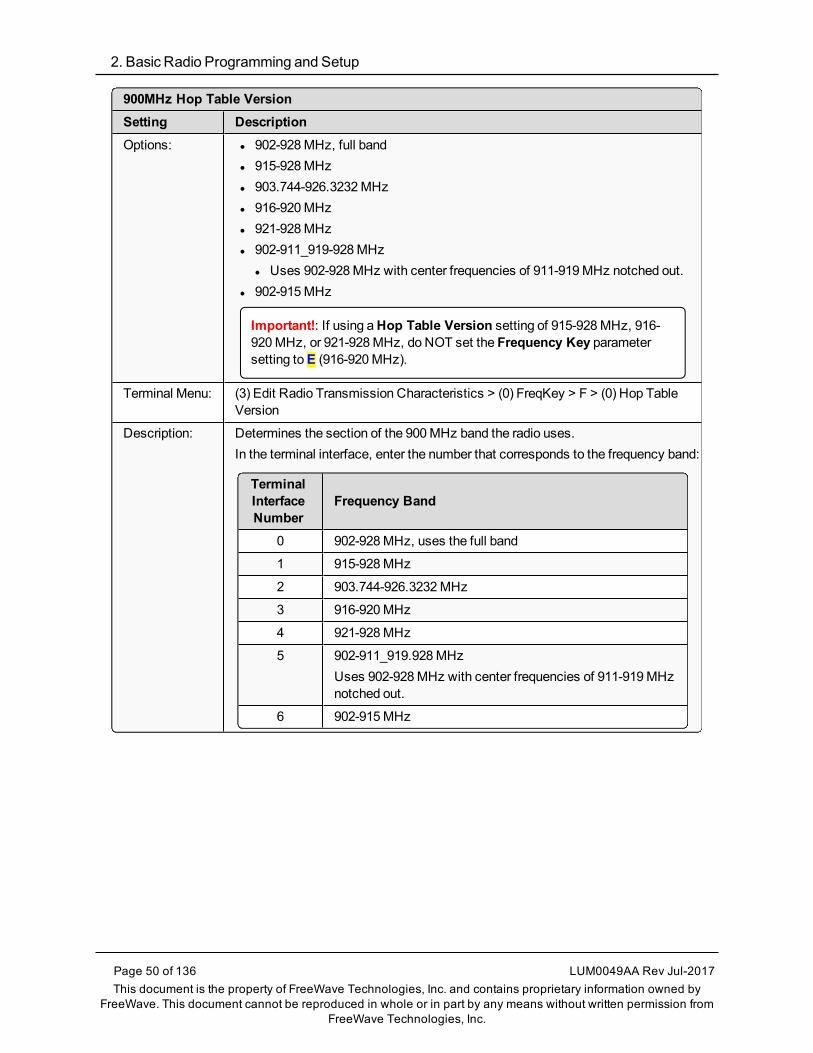
900MHz Hop Table VersionSetting DescriptionOptions: l 902-928MHz, full band
l 915-928MHzl 903.744-926.3232MHzl 916-920MHzl 921-928MHzl 902-911_919-928MHz
l Uses 902-928MHz with center frequencies of 911-919MHz notched out.l 902-915MHz
Important!: If using aHop Table Version setting of 915-928MHz, 916-920MHz, or 921-928MHz, do NOT set the Frequency Key parametersetting toE (916-920MHz).
Terminal Menu: (3) Edit Radio Transmission Characteristics > (0) FreqKey > F > (0) Hop TableVersion
Description: Determines the section of the 900MHz band the radio uses.In the terminal interface, enter the number that corresponds to the frequency band:
TerminalInterfaceNumber
Frequency Band
0 902-928MHz, uses the full band
1 915-928MHz
2 903.744-926.3232MHz
3 916-920MHz
4 921-928MHz
5 902-911_919.928MHzUses 902-928MHz with center frequencies of 911-919MHznotched out.
6 902-915MHz
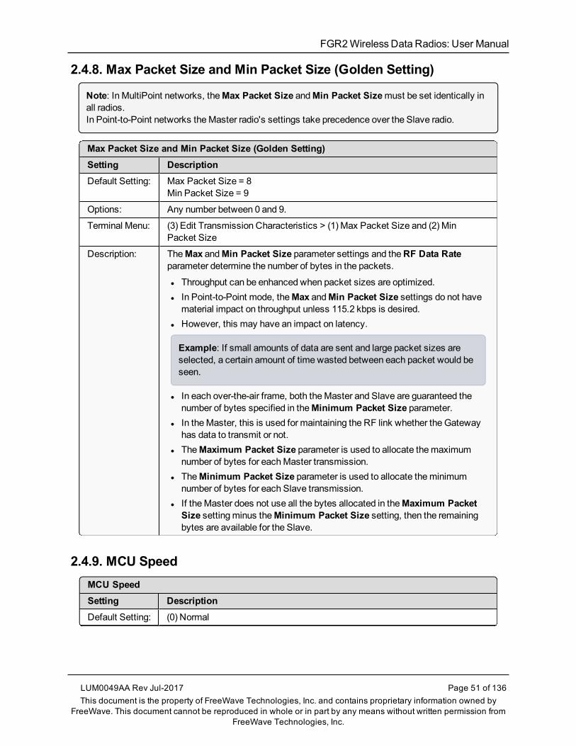
FGR2WirelessData Radios: User Manual
2.4.8. Max Packet Size and Min Packet Size (Golden Setting)
Note: In MultiPoint networks, theMax Packet Size andMin Packet Sizemust be set identically inall radios.In Point-to-Point networks theMaster radio's settings take precedence over the Slave radio.
Max Packet Size and Min Packet Size (Golden Setting)Setting DescriptionDefault Setting: Max Packet Size = 8
Min Packet Size = 9
Options: Any number between 0 and 9.
Terminal Menu: (3) Edit Transmission Characteristics > (1) Max Packet Size and (2) MinPacket Size
Description: TheMax andMin Packet Size parameter settings and theRF Data Rateparameter determine the number of bytes in the packets.
l Throughput can be enhanced when packet sizes are optimized.l In Point-to-Point mode, theMax andMin Packet Size settings do not havematerial impact on throughput unless 115.2 kbps is desired.
l However, this may have an impact on latency.
Example: If small amounts of data are sent and large packet sizes areselected, a certain amount of time wasted between each packet would beseen.
l In each over-the-air frame, both theMaster and Slave are guaranteed thenumber of bytes specified in theMinimum Packet Size parameter.
l In theMaster, this is used for maintaining the RF link whether the Gatewayhas data to transmit or not.
l TheMaximum Packet Size parameter is used to allocate themaximumnumber of bytes for eachMaster transmission.
l TheMinimum Packet Size parameter is used to allocate theminimumnumber of bytes for each Slave transmission.
l If theMaster does not use all the bytes allocated in theMaximum PacketSize settingminus theMinimum Packet Size setting, then the remainingbytes are available for the Slave.
2.4.9. MCU SpeedMCU SpeedSetting DescriptionDefault Setting: (0) Normal
LUM0049AA Rev Jul-2017 Page 51 of 136This document is the property of FreeWave Technologies, Inc. and contains proprietary information owned by
FreeWave. This document cannot be reproduced in whole or in part by any means without written permission fromFreeWave Technologies, Inc.
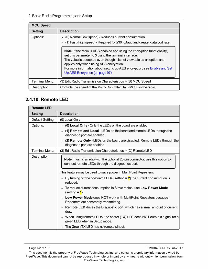
2. Basic Radio Programming and Setup
Page 52 of 136 LUM0049AA Rev Jul-2017This document is the property of FreeWave Technologies, Inc. and contains proprietary information owned by
FreeWave. This document cannot be reproduced in whole or in part by any means without written permission fromFreeWave Technologies, Inc.
MCU SpeedSetting DescriptionOptions: l (0) Normal (low speed) - Reduces current consumption.
l (1) Fast (high speed) - Required for 230 KBaud and greater data port rate.
Note: If the radio is AES enabled and using the encryption functionality,set this parameter to 3 using the terminal interface. The value is accepted even though it is not viewable as an option andapplies only when using AES encryption.For more information about setting up AES encryption, see Enable and SetUp AES Encryption (on page 97).
Terminal Menu: (3) Edit Radio Transmission Characteristics > (B) MCU Speed
Description: Controls the speed of theMicro Controller Unit (MCU) in the radio.
2.4.10. Remote LEDRemote LEDSetting DescriptionDefault Setting: (0) Local Only
Options: l (0) Local Only - Only the LEDs on the board are enabled.l (1) Remote and Local - LEDs on the board and remote LEDs through thediagnostic port are enabled.
l (2) Remote Only - LEDs on the board are disabled. Remote LEDs through thediagnostic port are enabled.
Terminal Menu: (3) Edit Radio Transmission Characteristics > (C) Remote LED
Description:Note: If using a radio with the optional 20-pin connector, use this option toconnect remote LEDs through the diagnostics port.
This featuremay be used to save power in MultiPoint Repeaters.
l By turning off the on-board LEDs (setting = 2) the current consumption isreduced.
l To reduce current consumption in Slave radios, use Low Power Mode(setting = 1).
l Low Power Mode does NOT work with MultiPoint Repeaters becauseRepeaters are constantly transmitting.
l Remote LED drives the Diagnostic port, which has a small amount of currentdraw.
l When using remote LEDs, the center (TX) LED does NOT output a signal for agreen LED when in Setupmode.
l TheGreen TX LED has no remote pinout.

FGR2WirelessData Radios: User Manual
2.4.11. Retry Time OutRetry Time OutSetting DescriptionDefault Setting: 255
Options: Any number between 0 and 255 inMultiPoint networks.
Note: Theminimum in 900MHz radios is 8 seconds.
Any number between 151 and 255 in Point-to-Point networks.
Terminal Menu: (3) Edit Transmission Characteristics > (8) Retry TimeOut
Description: TheRetry Time Out parameter in a Slave or Repeater sets the delay the unitwaits before dropping the connection to aMaster or Repeater.
l The factory default is set at themaximum of 255.l With a setting of 255, theMaster allows a Slave or Repeater to stayconnected as long as 1 packet in 255 is successfully received at theMaster.
l Themaximum settingmeans that if 1 packet in 255 is sent successfully fromtheMaster to the Slave or Repeater, the link is maintained.
l This allows a Slave or Repeater to drop a connection if less than 1 in 8consecutive packets is successfully received from theMaster.
TheRetry Time Out parameter is useful when aMultiPoint network has a rovingMaster or Slave. As the link gets weaker, a lower setting allows a poor link tobreak in search of a stronger one.
FREEWAVE Recommends: Setting theRetry Time Out parameter to20 in theMultiPoint Master is recommended in areas where severalFreeWave networks exist.This recommended setting allows Slaves and Repeaters to drop theconnection if the link becomes too weak, while at the same time preventerrant disconnects due to interference from neighboring networks.
Note: While intended primarily for MultiPoint networks, theRetry TimeOut parameter may be changed in Point-to-Point networks.However, the value in Point-to-Point mode should NOT be set to less than151.
LUM0049AA Rev Jul-2017 Page 53 of 136This document is the property of FreeWave Technologies, Inc. and contains proprietary information owned by
FreeWave. This document cannot be reproduced in whole or in part by any means without written permission fromFreeWave Technologies, Inc.

2. Basic Radio Programming and Setup
Page 54 of 136 LUM0049AA Rev Jul-2017This document is the property of FreeWave Technologies, Inc. and contains proprietary information owned by
FreeWave. This document cannot be reproduced in whole or in part by any means without written permission fromFreeWave Technologies, Inc.
2.4.12. RF Data Rate (Golden Setting)
Note: In MultiPoint networks, theRF Data Rate parameter must be set the same in all radios. Anyradio with anRF Data Rate setting different from theMaster will not establish a link. In Point-to-Point networks theMaster setting takes precedence over the Slave.
RF Data Rate (Golden Setting)Setting DescriptionDefault Setting: (3) Normal
Options: l (2) High - 153.6 kbpsl (3) Normal - 115.2 kbps
Terminal Menu: (3) Edit Transmission Characteristics > (4) RF Data Rate
Description:Important!: Do NOT confuse theRF Data Ratewith the serial port BaudRate.
FreeWave radios have theseRF Data Rate settings:l 2 (High).
l Use setting 2 (RF Speed of 153.6 kbps) when the radios are close togetherand need to optimize data throughput.
l 3 (Normal).l Use setting 3 (RF Speed of 115.2 kbps) when the radios are farther awayand a solid data link is preferred over data throughput.
2.4.13. RTS to CTS
Important!: TheRTS to CTS option is only available in RS232mode.It is NOT recommended to enable this feature when operating at Baud Rates above 38,400.
RTS to CTSSetting DescriptionDefault Setting: (0) Disabled
Options: l (0) Disabledl (1) Enabledl (2) Line Alarm
Note: Setting 2 is described in detail in theApplication Note #5437, DTRto CTS Line Alarm Feature.
Terminal Menu: (3) Edit Transmission Characteristics > (7) RTS to CTS

FGR2WirelessData Radios: User Manual
RTS to CTSSetting DescriptionDescription: Use this option to set the RTS line on theMaster radio to control the CTS line of
the Slave.WithRTS to CTS enabled:
l In MultiPoint networks, theMaster RTS line controls all Slave's CTS lines.l The CTS line stops functioning as flow control.l TheMaster senses the RTS line prior to all scheduled packet transmissions.
l If the state has changed, theMaster then transmits amessage to the Slavewith the new status. This transmission occurs regardless of data beingsent.
l If data is ready to be sent, the RTS status message is sent in addition to thedata.
l In Point-to-Point mode, theMaster continues sending the new status messageuntil it receives an acknowledgment from the Slave.
l In MultiPoint mode, theMaster repeats themessage the number of timesequal to theMaster Packet Repeat value in theMultiPoint Parameters tab.
l Master transmit times are completely asynchronous to the occurrence of anychange of the RTS line; the latency time from RTS to CTS is variable.
l TheMax andMin Packet Size parameters determine this duration.l Setting both parameters to their maximum value of 9 produces amaximumlatency time of approximately 21ms, given no Repeaters in the network.
l At theminimum settings forMax andMin Packet Size (0), the time isapproximately 5.9ms.
l This latency can increase significantly if packets are lost between theMasterand Slave.
l In Point-to-MultiPoint mode, no absolute guarantee is made that the statechange is communicated to all Slaves.
l In MultiPoint networks with Repeaters present, the latency is cumulative foreach serial Repeater.
Example: If the latency between theMaster and the first Repeater is15ms, and two serial Repeaters are present, the total latency is 45ms.(M—R1 (15ms) + R1—R2 (15ms) + R2—S (15ms) = 45ms).
Important!: TheRTS to CTS feature does NOT function in Point-to-Pointnetworks that contain a Repeater.If this feature is needed in such network, themode should be changed toPoint-to-MultiPoint.
l If DTR Connect on the Tool SuiteMultiPoint Parameters tab is enabled andset to 2, the RTS to CTS feature does not work.
LUM0049AA Rev Jul-2017 Page 55 of 136This document is the property of FreeWave Technologies, Inc. and contains proprietary information owned by
FreeWave. This document cannot be reproduced in whole or in part by any means without written permission fromFreeWave Technologies, Inc.

2. Basic Radio Programming and Setup
Page 56 of 136 LUM0049AA Rev Jul-2017This document is the property of FreeWave Technologies, Inc. and contains proprietary information owned by
FreeWave. This document cannot be reproduced in whole or in part by any means without written permission fromFreeWave Technologies, Inc.
RTS to CTSSetting Description
l If DTR Connect is enabled and set to 1, RTS to CTS mode takes precedenceover the functionality of the CTS line on the Slave relating to theDTRConnect feature.
2.4.14. Slave Security
Note: TheSlave Security parameter has no effect in Point-to-MultiPoint networks where theNetwork ID is used.
Slave SecuritySetting DescriptionDefault Setting: (0) On
Options: (0) On(1) Off
Terminal Menu: (3) Edit Transmission Characteristics > (6) Slave Security
Description: l Slave Security allows Slave radios to accept transmissions from aMaster notincluded in the Call Book.l The default setting of 0 (On) means only Masters in the Slave radio's CallBook may link to that Slave.
l TheSlave Security parameter may be disabled (setting of 1) allowing anyMaster to call the Slave.
l TheSlave Security parameter must be set to 1when the unit is operating inMode 6, Slave/Master Switchable or a Point-to-Point network where the Slavemay need to accept calls frommore than 10 different Masters.l SeeApplication Note #5476: Mode 6 for additional information.
l When theSlave Security parameter is set to 1, the radio accepts calls fromany other radio.
l Additional network security measures may be taken to prevent unauthorizedaccess (e.g., changing default settings for Frequency Key, Hop Table, orFrequency Zones).
2.4.15. Transmit PowerTransmit PowerSetting DescriptionDefault Setting: 10
Options: Any number between 0 and 10
Terminal Menu: (3) Edit Transmission Characteristics > (5) RF Xmit Power

FGR2WirelessData Radios: User Manual
Transmit PowerSetting DescriptionDescription: Sets the output power of the radio in dBm.
l In FGR2 radios, a setting of 10 is approximately 1W of output power.
When testing radios, and they are in close proximity to one another,set the Transmit Power parameter to a low number.When deploying radios to the field, raise the Transmit Powernumber accordingly.
Important!: This table is for reference only. All Transmit Power settings below 9 are approximate.
Setting Power (in mW) forFGR2 Radios
0 5
1 10
2 35
3 80
4 140
5 230
6 330
7 480
8 600
9 800
10 1000
2.4.16. Transmit RateTransmit RateSetting DescriptionDefault Setting: (1) Normal
Options: l 0 - Diagnosticsl 1 - Normal
Terminal Menu: (3) Edit Transmission Characteristics > (3) Xmit Rate
LUM0049AA Rev Jul-2017 Page 57 of 136This document is the property of FreeWave Technologies, Inc. and contains proprietary information owned by
FreeWave. This document cannot be reproduced in whole or in part by any means without written permission fromFreeWave Technologies, Inc.

2. Basic Radio Programming and Setup
Page 58 of 136 LUM0049AA Rev Jul-2017This document is the property of FreeWave Technologies, Inc. and contains proprietary information owned by
FreeWave. This document cannot be reproduced in whole or in part by any means without written permission fromFreeWave Technologies, Inc.
Transmit RateSetting DescriptionDescription: FGR2 radios have two available Transmit Rate settings.
l The setting for normal operation of the radio is 1.l When set to 0, the radios transmit back and forth continuously regardless ifthey have any actual data.
l 0 should be used only as a diagnostic tool and not for normal operation.l The strength of the signal may be gauged by the Clear to Send (CTS) LED.l A solid red ( ) CTS LED indicates a strong signal.l A blinking ( ) CTS LED indicates a weaker signal.
0 is useful to qualitatively gauge signal strength in Point-to-Point mode.

FGR2WirelessData Radios: User Manual
3. ConfiguringPoint-to-MultiPoint Networks
When installingMultiPoint networks it is important to do some up front planning around thedevices to implement and the route the data is going to take back to theMaster. A MultiPointnetwork can contain the following devices:
l Only oneMaster. All communications are from and to theMaster.l An unlimited number of Slave radios (remote sites).l An unlimited number of Repeaters between any Slave and theMaster.l Serial Repeaters can be Slave radios and Repeaters at the same time.
This section provides details about the setup that applies specifically to aMultiPoint network:l Point to MultiPoint network characteristics.l Using the Network ID or the Call Book to establish which radios in the network cancommunicate with each other.
l Using subnet IDs to route traffic through the network, back to theMaster.l Settings and recommendations for additional parameters that apply to aMultiPointnetwork.
l Conserving power in deviceswithin the network.l Running network diagnostics.
Note: See Routing Communications through the Network (on page 68) and Assigning Subnet IDValues (on page 68) for additional information.
LUM0049AA Rev Jul-2017 Page 59 of 136This document is the property of FreeWave Technologies, Inc. and contains proprietary information owned by
FreeWave. This document cannot be reproduced in whole or in part by any means without written permission fromFreeWave Technologies, Inc.

3. Configuring Point-to-MultiPoint Networks
Page 60 of 136 LUM0049AA Rev Jul-2017This document is the property of FreeWave Technologies, Inc. and contains proprietary information owned by
FreeWave. This document cannot be reproduced in whole or in part by any means without written permission fromFreeWave Technologies, Inc.
3.1. Point to MultiPoint Network CharacteristicsA Point to MultiPoint network has these unique characteristics:
l Golden Settings (on page 60).l Master to Slave Communications (on page 60).l Slave toMaster Communications (on page 60).
3.1.1. Golden SettingsA Point-to-MultiPoint network requires that the Golden Settings (described in Golden Settings (onpage 40)) are set the same onALL radios in the network.If several independent MultiPoint networks are located in close proximity, the planning becomesmore critical. It is very important to include asmuch frequency and time diversity as possible usingdifferentMin and Max Packet Size. In some instances the use of theMultiMaster Sync optionmay be required.In almost all MultiPoint networks, the Frequency Key is the same for all radios. In other networks,where parallel Repeaters are introduced, the Frequency Key value needs to change.
3.1.2. Master to Slave CommunicationsMaster - to - Slave communicationswithin aMultiPoint network have these characteristics:
l Data packets sent from theMaster include a 32-bit CRC.l TheMaster repeats its data broadcast between 0 to 9 times, depending on theMasterPacket Repeat setting. For more information, seeMaster Packet Repeat (on page 74).
l A Slave or Repeater does not send acknowledgments to theMaster when it receives data.l When any Slave in the network receives the data packet from theMaster with the 32-bitCRC, that Slave ignores any additional repeats of the data, and passes the data to itsdata port.
l Repeaters in the network send data to Slave radios and other Repeaters.
3.1.3. Slave to Master CommunicationsSlave - to - Master communicationswithin aMultiPoint network have these characteristics:
l Data packets sent from the Slave to theMaster include a 32-bit CRC.l When theMaster successfully receives data, it sends an acknowledgment to the Slave andpasses the data out its data port.
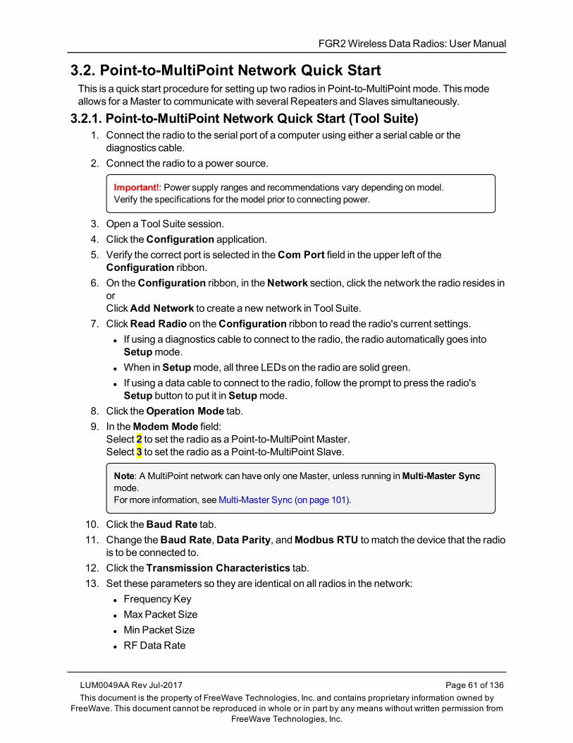
FGR2WirelessData Radios: User Manual
3.2. Point-to-MultiPoint Network Quick StartThis is a quick start procedure for setting up two radios in Point-to-MultiPoint mode. Thismodeallows for aMaster to communicate with several Repeaters and Slaves simultaneously.
3.2.1. Point-to-MultiPoint Network Quick Start (Tool Suite)1. Connect the radio to the serial port of a computer using either a serial cable or the
diagnostics cable.2. Connect the radio to a power source.
Important!: Power supply ranges and recommendations vary depending onmodel.Verify the specifications for themodel prior to connecting power.
3. Open a Tool Suite session.4. Click theConfiguration application.5. Verify the correct port is selected in theCom Port field in the upper left of the
Configuration ribbon.6. On theConfiguration ribbon, in theNetwork section, click the network the radio resides in
orClickAdd Network to create a new network in Tool Suite.
7. ClickRead Radio on theConfiguration ribbon to read the radio's current settings.l If using a diagnostics cable to connect to the radio, the radio automatically goes intoSetupmode.
l When inSetupmode, all three LEDs on the radio are solid green.l If using a data cable to connect to the radio, follow the prompt to press the radio'sSetup button to put it inSetupmode.
8. Click theOperation Mode tab.9. In theModem Mode field:
Select 2 to set the radio as a Point-to-MultiPoint Master.Select 3 to set the radio as a Point-to-MultiPoint Slave.
Note: A MultiPoint network can have only oneMaster, unless running inMulti-Master Syncmode.For more information, seeMulti-Master Sync (on page 101).
10. Click theBaud Rate tab.11. Change theBaud Rate,Data Parity, andModbus RTU to match the device that the radio
is to be connected to.12. Click the Transmission Characteristics tab.13. Set these parameters so they are identical on all radios in the network:
l Frequency Keyl MaxPacket Sizel Min Packet Sizel RFData Rate
LUM0049AA Rev Jul-2017 Page 61 of 136This document is the property of FreeWave Technologies, Inc. and contains proprietary information owned by
FreeWave. This document cannot be reproduced in whole or in part by any means without written permission fromFreeWave Technologies, Inc.

3. Configuring Point-to-MultiPoint Networks
Page 62 of 136 LUM0049AA Rev Jul-2017This document is the property of FreeWave Technologies, Inc. and contains proprietary information owned by
FreeWave. This document cannot be reproduced in whole or in part by any means without written permission fromFreeWave Technologies, Inc.
Note: If several independent MultiPoint networks are located in close proximity, it is veryimportant to include as much frequency and time diversity as possible through use of differentFrequency Key,Min and Max Packet Size, andHop Table settings.
14. Click theMultiPoint Parameters tab.15. In theNetwork ID field, set to any value between 1 and 4095.
FREEWAVE Recommends: Set theNetwork ID to the last three or four digits of theMasterradio's serial number if it is below 4095.This valuemust be the same in all radios in the network.
Important!: A setting of 255 disables theNetwork ID feature and enables the Call Book.
16. Send the parameter settings by either:l Sending all the settings for all parameters:In theConfiguration application, on theNetwork Title ribbon, clickAll.
l Sending only the changed parameters:In theConfiguration application, on theNetwork Title ribbon, clickQuick.
Note: This option is only available if Read Radio is clicked and parameter settings areNOT sent from a template to the radio.
3.2.2. Point-to-MultiPoint Network Quick Start (Terminal Interface)1. Connect the radio to the serial port of a computer using either a serial cable or the
diagnostics cable.2. Connect the radio to a power source.
Important!: Power supply ranges and recommendations vary depending onmodel.Verify the specifications for themodel prior to connecting power.
3. Open a terminal emulator session.
Use the Tool SuiteSetup Terminal application if a terminal emulator is not available.
4. Connect to COMx (where 'x' is the number of the COMconnected port).5. Set these options:
l Data Rate: 19,200l Data Bits: 8l Parity:Nonel Stop Bits: 1l Flow Control:None
6. Press theSetup button on the radio.If using the diagnostics cable, press <Shift+U>.

FGR2WirelessData Radios: User Manual
l The three LEDs on the radio should all turn green , indicatingSetupmode.l TheMainmenu appears on the screen.
7. Press <0> to access theOperation Modemenu.8. Press <2> to set the radio as a Point-to-MultiPoint Master or
Press <3> to set the radio as a Point-to-MultiPoint Slave.9. Press <Esc> to return to theMainmenu.
Note: A MultiPoint network can have only oneMaster, unless running inMulti-Master Syncmode.For more information, seeMulti-Master Sync (on page 101).
10. Press <1> on theMainmenu.11. Change theBaud Rate,Data Parity, andModbus RTU to match the device that the
radio is to be attached to.12. Press <Esc> to return to theMainmenu.13. Press <3> in theMainmenu.14. Set these parameters so they are the same on all radios in the network:
l FreqKeyl MaxPacket Sizel Min Packet Sizel RFData Rate
Note: The Frequency Key option is located in the F submenu after pressing 0 to access theFrequency Keymenu inMainmenu 3.
15. Press <Esc> to return to theMainmenu.16. Press <5> on theMainmenu.17. In theNetwork ID field, set the value to any value between 1 and 4095.
Note: A 255 setting disables theNetwork ID feature and enables the Call Book.
FREEWAVE Recommends: Set theNetwork ID to the last three or four digits of theMasterradio's serial number if it is below 4095.This valuemust be the same in all radios in the network.
18. Press <Esc> to exit theSetupmenu and resume normal radio operation.
LUM0049AA Rev Jul-2017 Page 63 of 136This document is the property of FreeWave Technologies, Inc. and contains proprietary information owned by
FreeWave. This document cannot be reproduced in whole or in part by any means without written permission fromFreeWave Technologies, Inc.
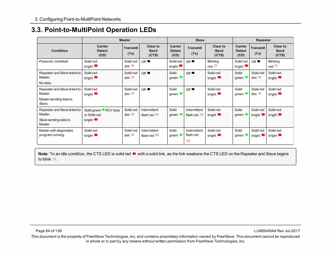
3. Configuring Point-to-MultiPoint Networks
Page 64 of 136 LUM0049AA Rev Jul-2017This document is the property of FreeWave Technologies, Inc. and contains proprietary information owned by FreeWave. This document cannot be reproduced
in whole or in part by any means without written permission from FreeWave Technologies, Inc.
3.3. Point-to-MultiPoint Operation LEDsMaster Slave Repeater
ConditionCarrierDetect(CD)
Transmit(Tx)
Clear toSend(CTS)
CarrierDetect(CD)
Transmit(Tx)
Clear toSend(CTS)
CarrierDetect(CD)
Transmit(Tx)
Clear toSend(CTS)
Powered, not linked Solid redbright
Solid reddim
Off Solid redbright
Off Blinkingred
Solid redbright
Off Blinkingred
Repeater and Slave linked toMaster.
No data.
Solid redbright
Solid reddim
Off Solidgreen
Off Solid redbright
Solidgreen
Solid reddim
Solid redbright
Repeater and Slave linked toMaster.
Master sending data toSlave.
Solid redbright
Solid reddim
Off Solidgreen
Off Solid redbright
Solidgreen
Solid reddim
Solid redbright
Repeater and Slave linked toMaster.
Slave sending data toMaster.
Solid green RCVdataor Solid redbright
Solid reddim
Intermittentflash red
Solidgreen
Intermittentflash red
Solid redbright
Solidgreen
Solid redbright
Solid redbright
Master with diagnosticsprogram running.
Solid redbright
Solid reddim
Intermittentflash red
Solidgreen
Intermittentflash red
Solid redbright
Solidgreen
Solid redbright
Solid redbright
Note: *In an idle condition, the CTS LED is solid red with a solid link, as the link weakens the CTS LED on the Repeater and Slave beginsto blink .
FGR2WirelessData Radios: User Manual
3.4. Overlapping MultiPoint NetworksOverlappingMultiPoint networksmay be set up effectively when several key parameters are setcorrectly. OverlappingMultiPoint networks are defined as networks using different Master radios,which share or overlap in a specific geographic area. It may also include collocated radiosconfigured into different networks.For more information, see Application Note #5412,Synchronizing Collocated Masters (Multi-Master Sync Mode) (available fromwww.freewave.com).CollocatedMultiPoint networks require these parameters be unique for each network:
l Network ID (unless using the Call Book)l Frequency Key (with Repeater Frequency)l MaxPacket Sizel Min Packet Size
Note: For more information about the installation of Point-to-MultiPoint networks, contact FreeWaveTechnical Support.See Contact FreeWave Technical Support on page 9
3.5. Establishing Communication with Other Radios in aMultiPoint NetworkFor the radios in the network to communicate successfully, the radio needs to know what otherdevices are available for them to communicate with. Use theNetwork ID or the Call Book.
FREEWAVE Recommends: While the Call Book is an option in Point-to-MultiPoint networks,FreeWave strongly recommends using theNetwork ID feature in most applications.If a largeMultiPoint network is implemented using the Call Book and a radio needs to be added to orreplaced in the network, each radio in the network must be physically reprogrammed and the newserial number entered in the radio's Call Book.This can be a time consuming process and can cause a delay in getting the network back up andrunning.Because theNetwork ID does not use serial numbers, MultiPoint Master radios and Repeaters maybe added or replaced without reprogramming each Slave radio in the network.
3.5.1. Using the Network ID in MultiPoint NetworksTheNetwork ID parameter is located on theMultiPoint Parameters tab. Assign each radio in asingle network the sameNetwork ID. Slave radios link with the first Master or Repeater it hearsthat has amatchingNetwork ID.When setting theNetwork ID:
l The value can be any value between 1 and 4095, except 255.l 255 enables the Call Book.
l To help ensure the ID is unique to the network, avoid using numbers that coincide withnearby landmarks or highways.
LUM0049AA Rev Jul-2017 Page 65 of 136This document is the property of FreeWave Technologies, Inc. and contains proprietary information owned by
FreeWave. This document cannot be reproduced in whole or in part by any means without written permission fromFreeWave Technologies, Inc.
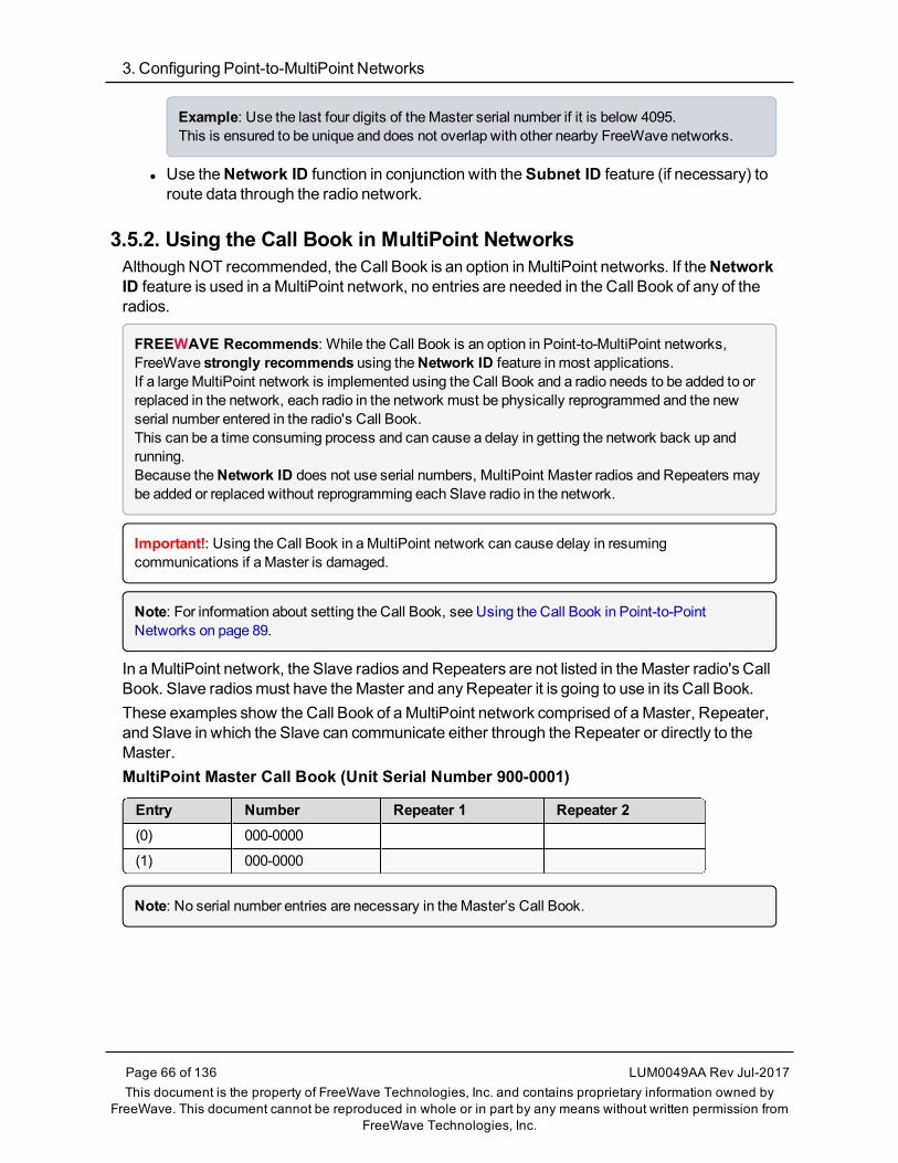
3. Configuring Point-to-MultiPoint Networks
Page 66 of 136 LUM0049AA Rev Jul-2017This document is the property of FreeWave Technologies, Inc. and contains proprietary information owned by
FreeWave. This document cannot be reproduced in whole or in part by any means without written permission fromFreeWave Technologies, Inc.
Example: Use the last four digits of theMaster serial number if it is below 4095.This is ensured to be unique and does not overlap with other nearby FreeWave networks.
l Use theNetwork ID function in conjunction with theSubnet ID feature (if necessary) toroute data through the radio network.
3.5.2. Using the Call Book in MultiPoint NetworksAlthough NOT recommended, the Call Book is an option in MultiPoint networks. If theNetworkID feature is used in aMultiPoint network, no entries are needed in the Call Book of any of theradios.
FREEWAVE Recommends: While the Call Book is an option in Point-to-MultiPoint networks,FreeWave strongly recommends using theNetwork ID feature in most applications.If a largeMultiPoint network is implemented using the Call Book and a radio needs to be added to orreplaced in the network, each radio in the network must be physically reprogrammed and the newserial number entered in the radio's Call Book.This can be a time consuming process and can cause a delay in getting the network back up andrunning.Because theNetwork ID does not use serial numbers, MultiPoint Master radios and Repeaters maybe added or replaced without reprogramming each Slave radio in the network.
Important!: Using the Call Book in aMultiPoint network can cause delay in resumingcommunications if a Master is damaged.
Note: For information about setting the Call Book, see Using the Call Book in Point-to-PointNetworks on page 89.
In aMultiPoint network, the Slave radios and Repeaters are not listed in theMaster radio's CallBook. Slave radiosmust have theMaster and anyRepeater it is going to use in its Call Book.These examples show the Call Book of aMultiPoint network comprised of aMaster, Repeater,and Slave in which the Slave can communicate either through the Repeater or directly to theMaster.MultiPoint Master Call Book (Unit Serial Number 900-0001)
Entry Number Repeater 1 Repeater 2(0) 000-0000
(1) 000-0000
Note: No serial number entries are necessary in theMaster’s Call Book.

FGR2WirelessData Radios: User Manual
MultiPoint Repeater Call Book (Unit Serial Number 900-0002)
Entry Number Repeater 1 Repeater 2(0) 900-0001
(1) 000-0000
MultiPoint Slave Call Book (Unit Serial Number 900-0003)
Entry Number Repeater 1 Repeater 2(0) 900-0001
(1) 900-0002
(2) 000-0000
At times, the Slave radios need to be forced to go through a specific MultiPoint Repeater.In this scenario, the Slave radio's Call Book should contain only the serial number for thatRepeater as the entry on line 0.
3.5.3. Programming Point-to-MultiPoint Extended Call BookIn aMultiPoint network, Slave radios can be programmed to roam betweenMaster radios andRepeaters using theMultiPointExtended Call Book function. Slave radios with Call Book, asconfigured in this procedure, communicate with any radio whose serial number appears in any ofthe three columns.
Procedure1. Set theNetwork ID to 255.2. In the Call Book, enter 999-9999 as the last entry in the first and second columns.3. In the Call Book, set Entry to Call toAll.
Figure 19: HyperTerminal PTMP Extended Call Book
LUM0049AA Rev Jul-2017 Page 67 of 136This document is the property of FreeWave Technologies, Inc. and contains proprietary information owned by
FreeWave. This document cannot be reproduced in whole or in part by any means without written permission fromFreeWave Technologies, Inc.

3. Configuring Point-to-MultiPoint Networks
Page 68 of 136 LUM0049AA Rev Jul-2017This document is the property of FreeWave Technologies, Inc. and contains proprietary information owned by
FreeWave. This document cannot be reproduced in whole or in part by any means without written permission fromFreeWave Technologies, Inc.
3.6. Routing Communications through the NetworkWhen using theNetwork ID, a Repeater or Slave links to the first Repeater or Master it hearswith the same ID.
l Use Subnet IDs to determine the path a Repeater or Slave uses to communicate back totheMaster.
l Subnet IDs are particularly helpful to force:l TwoRepeaters in the same network to operate in series rather than in parallel.l Slave radios to communicate to a specific Repeater for load balancing purposes.
Note: Forcing the communications path optimizes the performance of the network by ensuring theRepeater or Slave links to a Repeater or Master with robust RF communications. Subnet IDs canhelp tominimize latency.
3.6.1. Assigning Subnet ID ValuesSubnet IDs consist of two parts, both available on theMultiPoint Parameters tab:
l Rx - This setting identifies which radio a Repeater or Slave listens to.l In the terminal interface, this is theRcv Subnet ID.
l Tx - This setting identifies the ID this device transmits on and which devices listen to it.l The Tx Subnet ID parameter is relevant for MultiPoint Master radios and Repeatersonly.
l In the terminal interface, this is theXmt Subnet ID.l The default (disable) setting for bothRx and Tx isF, F.
l This is a visual way to indicate that the device is the final in the line of communication anddoes not use a subnet ID.
l AMultiPoint Slave with aSubnet ID of F, F does not roam from one Repeater or networkto the next.l It only links to aMaster or Repeater that has either a Transmit Subnet setting of 0 or anF, F Subnet ID.
l Setting bothRx and Tx Subnet ID to 0 allows amobile Slave to roam from subnet tosubnet, and possibly from network to network, provided theNetwork ID,Max and MinPacket Size, andRF Data Rates are the same between networks.
The examples in this section show the subnet definitions from theMaster radio through thenetwork to the Slave radios. When the subnet path is defined, the Slave radios can follow theroute back to theMaster.
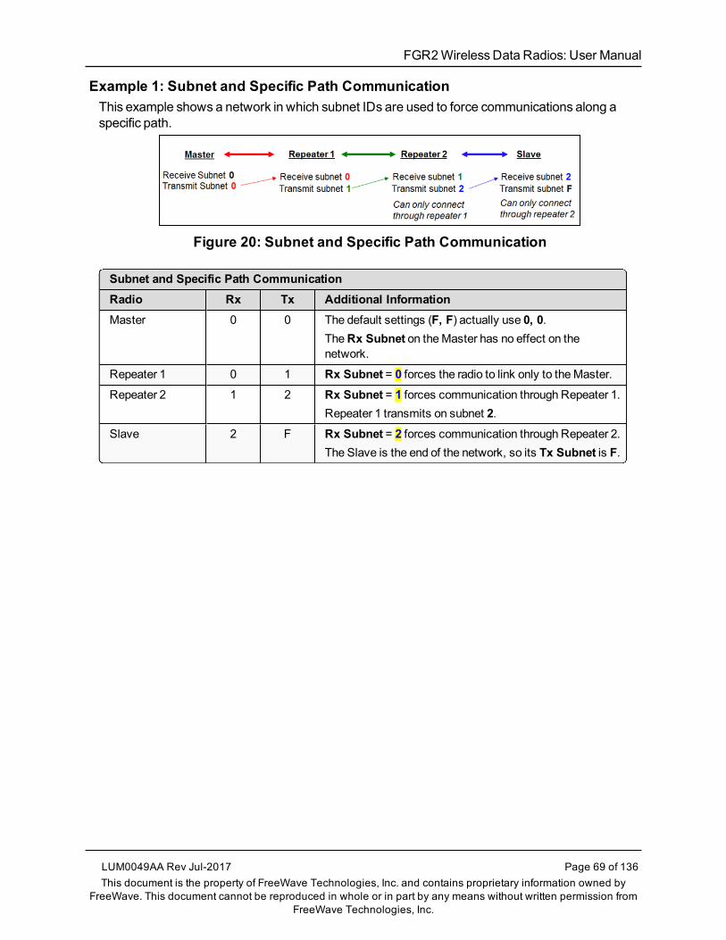
FGR2WirelessData Radios: User Manual
Example 1: Subnet and Specific Path CommunicationThis example shows a network in which subnet IDs are used to force communications along aspecific path.
Figure 20: Subnet and Specific Path Communication
Subnet and Specific Path CommunicationRadio Rx Tx Additional InformationMaster 0 0 The default settings (F, F) actually use 0, 0.
TheRx Subnet on theMaster has no effect on thenetwork.
Repeater 1 0 1 Rx Subnet = 0 forces the radio to link only to theMaster.Repeater 2 1 2 Rx Subnet = 1 forces communication through Repeater 1.
Repeater 1 transmits on subnet 2.Slave 2 F Rx Subnet = 2 forces communication through Repeater 2.
The Slave is the end of the network, so its Tx Subnet is F.
LUM0049AA Rev Jul-2017 Page 69 of 136This document is the property of FreeWave Technologies, Inc. and contains proprietary information owned by
FreeWave. This document cannot be reproduced in whole or in part by any means without written permission fromFreeWave Technologies, Inc.

3. Configuring Point-to-MultiPoint Networks
Page 70 of 136 LUM0049AA Rev Jul-2017This document is the property of FreeWave Technologies, Inc. and contains proprietary information owned by
FreeWave. This document cannot be reproduced in whole or in part by any means without written permission fromFreeWave Technologies, Inc.
Example 2: Subnet and Communication Required through RepeatersThis example shows:
l Repeater 2must communicate through Repeater 1.l The Slave connected to Repeater 1must route through Repeater 1.l The other two Slave radiosmust route through Slave/Repeater 2.
Figure 21: Subnet and Communication Required through Repeaters
Subnet and Communication Required through RepeatersRadio Rx Tx Additional InformationMaster 0 0 The default settings (F, F) actually use 0, 0.
TheRx Subnet on theMaster has no effect on the network.Slave 1 0 F Rx Subnet = 0 forces the radio to link only to theMaster.
The Slave does not transmit to any device except theMaster,so its Tx Subnet is F.
Repeater 1 0 1 Rx Subnet = 0 forces the radio to link only to theMaster.Transmits on subnet 1.
Slave 2 0 F Rx Subnet = 0 forces the radio to link only to theMaster.Slave/Repeater 2 1 2 Rx Subnet = 1 forces the radio to link only to Repeater 1.
It transmits on Tx Subnet 2 to Slave 4 and 5.Slave 3 1 F Rx Subnet = 1 forces the radio to link only to Repeater 1.
The Slave does not transmit to any device except Repeater1, so its Tx Subnet is F.
Slave 4 2 F Rx Subnet = 2 forces the radio to link with Slave/Repeater 2.Slave 5 2 F Rx Subnet = 2 forces the radio to link with Slave/Repeater 2.
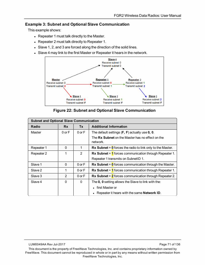
FGR2WirelessData Radios: User Manual
Example 3: Subnet and Optional Slave CommunicationThis example shows:
l Repeater 1must talk directly to theMaster.l Repeater 2must talk directly to Repeater 1.l Slave 1, 2, and 3 are forced along the direction of the solid lines.l Slave 4may link to the first Master or Repeater it hears in the network.
Figure 22: Subnet and Optional Slave Communication
Subnet and Optional Slave CommunicationRadio Rx Tx Additional InformationMaster 0 or F 0 or F The default settings (F, F) actually use 0, 0.
TheRx Subnet on theMaster has no effect on thenetwork.
Repeater 1 0 1 Rx Subnet = 0 forces the radio to link only to theMaster.Repeater 2 1 2 Rx Subnet = 1 forces communication through Repeater 1.
Repeater 1 transmits on SubnetID 1.
Slave 1 0 0 or F Rx Subnet = 0 forces communication through theMaster.Slave 2 1 0 or F Rx Subnet = 1 forces communication through Repeater 1.Slave 3 2 0 or F Rx Subnet = 2 forces communication through Repeater 2.Slave 4 0 0 The 0, 0 setting allows the Slave to link with the:
l first Master orl Repeater it hears with the sameNetwork ID.
LUM0049AA Rev Jul-2017 Page 71 of 136This document is the property of FreeWave Technologies, Inc. and contains proprietary information owned by
FreeWave. This document cannot be reproduced in whole or in part by any means without written permission fromFreeWave Technologies, Inc.

3. Configuring Point-to-MultiPoint Networks
Page 72 of 136 LUM0049AA Rev Jul-2017This document is the property of FreeWave Technologies, Inc. and contains proprietary information owned by
FreeWave. This document cannot be reproduced in whole or in part by any means without written permission fromFreeWave Technologies, Inc.
3.7. Setting Other MultiPoint ParametersThe other MultiPoint Parameters options allow you tomodify several different parameters in theradio that determine the characteristics of aMultiPoint network.
l In Tool Suite, set these parameters in theMultiPoint Parameters tab.l These settings are available in theMultiPoint Parameters menu in the terminal interface.
Note: See the Parameter Preference (on page 10) for a description of the parameter table's content.
3.7.1. 1 PPS Enable Delay
Important!: When 1 PPS is enabled, theMaster radio must have a 1 PPS pulse on its DTR pin,otherwise the RF network does not function.
1 PPS Enable DelaySetting DescriptionDefault Setting: 255
Options: l 255 to disable 1 PPSl 0 to 254 to enter the delay
Terminal Menu: (5) Edit MultiPoint Parameters > (9) 1 PPS Enable/Delay
Description: The 1 PPS Enable/Delay setting allows a 1PPS signal to propagate from theMaster to all Slave in aMultiPoint network.When this parameter is enabled a properly generated pulse applied on the DTRline of theMaster provides a 1 PPS pulse on the CD line of any Slave in thenetwork.
Setup 1PPS Enable/Delay1. On theMaster radio, set the 1 PPS Enable/Delay parameter to 0.
Note: TheMaster must have a 1 PPS pulse on the DTR pin, otherwise the RF network willnot function.
2. Enable the 1 PPS Enable/Delay parameter on the Slave radios.Slave radios are calibrated at the factory.

FGR2WirelessData Radios: User Manual
Calibrate a Slave Radio in 1PPS Enable/Delay Mode1. On theMaster radio, trigger an oscilloscope on the 1 PPS pulse on the DTR line.2. Monitor the CD line of the Slave radio.3. If the timing on the Slave radio differs from theMaster it may be adjusted via the value in the
Slave radio's 1 PPS Enable/Delay parameter.The difference in time between each incremental integer value is 542.534 nanoseconds (ns).Changing the parameter to higher values decreases the Slave radio time delay and changing theparameter to lower values increases the time delay.When properly calibrated, the CD line Slave radio outputs a pulse that goes high for about 2ms insyncwith the 1 PPS pulse on theMaster radio. The output on the Slave radio occurs within 20microseconds of the input to theMaster.
3.7.2. DiagnosticsDiagnosticsSetting DescriptionDefault Setting: 0 (Disabled)
Options: Any number between 0 and 128
Terminal Menu: (5) Edit MultiPoint Parameters > (B) Diagnostics
Description: Allows diagnostics data in theNetwork Diagnostics in Tool Suite to be viewed attheMaster radio in parallel with application data.
l The setting in this parameter determines how many slots out of 128 arededicated to diagnostics.
l Diagnostics is always secondary to actual transmitted data.
Example: If set to 10, 1 out of every 10 data slots is for diagnostics data.If set to 100, 1 out of every 100 data slots is for diagnostics data.
Note: For more information, see Reading Diagnostics in Tool Suite onpage 82.
3.7.3. DTR ConnectDTR ConnectSetting DescriptionDefault Setting: (0) Off
Options: l (0) Off - When set to off in the Slave radio, the radio transmits when the data isreceived.
l (1) DTR Sensing - Forms a Point-to-Point link with theMaster radio when theDTR line is high to send data.
l (2) Burst Mode - The radio transmits data in bursts.
LUM0049AA Rev Jul-2017 Page 73 of 136This document is the property of FreeWave Technologies, Inc. and contains proprietary information owned by
FreeWave. This document cannot be reproduced in whole or in part by any means without written permission fromFreeWave Technologies, Inc.

3. Configuring Point-to-MultiPoint Networks
Page 74 of 136 LUM0049AA Rev Jul-2017This document is the property of FreeWave Technologies, Inc. and contains proprietary information owned by
FreeWave. This document cannot be reproduced in whole or in part by any means without written permission fromFreeWave Technologies, Inc.
DTR ConnectSetting DescriptionTerminal Menu: (5) MultiPoint parameters > (4) DTR Connect
Description: Determines how the radio sends its data.
Note: This mode is valuable when a network has many low data ratedevices and to increase overall network capacity.
The radio has two separate transmit and receive user data buffers of 2kb each.
Caution: In case of a buffer overflow, the radio outputs unpredictabledata.
3.7.4. Local ModeLocal ModeSetting DescriptionDefault Setting: (0) Disabled
Options: (0) Disabled, (1) Enabled
Terminal Menu: (5) Edit MultiPoint Parameters > (E) Local Access
Description: Enable Local Mode to access a Slave radio with a local Master radio.
Important!: This Master does NOT take the place of the network Master.
Note: For more information, seeApplication Note #5457, Local Mode(available from www.freewave.com).
3.7.5. Master Packet Repeat
Note: When using the radio inModbus RTU mode, theMaster Packet Repeat settingmust matchin every radio, regardless of whether the network is in Point-to-Point or MultiPoint mode.
Master Packet RepeatSetting DescriptionDefault Setting: 3
Options: Any number between 0 and 9.
Terminal Menu: (5) Edit MultiPoint Parameters > (1) Master Packet Repeat

FGR2WirelessData Radios: User Manual
Master Packet RepeatSetting DescriptionDescription: In a Point-to-MultiPoint network, Slave radios do not acknowledge transmissions
from theMaster.
l If Slave radios did acknowledge all data transmissions, in a large network, theMaster would soon become overwhelmed with acknowledgments from theSlaves.
l Without acknowledgments, 100% confidence every Slave radio has receivedevery packet cannot bemet.
l To address this issue, change theMaster Packet Repeat parameter,assigning a value between 0 (the packet is transmitted once) to 9 (the packetis transmitted 10 times).
For networks with solid RF links, this parameter should be set to a low value (e.g.,1 or 2).l If a network has someweak or marginal links it should be set with highervalues.
l If a Slave radio receives a good packet from aMaster more than once itdiscards the repeated packets.
l Similarly, after aMultiPoint Repeater receives a good packet from theMaster,it discards any further repeated packets.
l In turn, the Repeater sends the packet out to the next Repeater or Slaves thenumber of times corresponding to its ownMaster Packet Repeat setting.
Increasing theMaster Packet Repeat setting increases the probability of apacket getting through, but also increases latency in the network because eachpacket from theMaster or Repeater is being sent multiple times.
Note: Therefore, it is important to find the optimal mix between networkrobustness, throughput, and latency.In general, a setting of 2 to 3works well for most well designed networks.
TheMaster Packet Repeat parameter may be set to 0 if the user software iscapable of, or requires acknowledgment.In this case, if theMaster sends a packet that the Slave radio does not receive,the user software controls the retries as needed.
LUM0049AA Rev Jul-2017 Page 75 of 136This document is the property of FreeWave Technologies, Inc. and contains proprietary information owned by
FreeWave. This document cannot be reproduced in whole or in part by any means without written permission fromFreeWave Technologies, Inc.

3. Configuring Point-to-MultiPoint Networks
Page 76 of 136 LUM0049AA Rev Jul-2017This document is the property of FreeWave Technologies, Inc. and contains proprietary information owned by
FreeWave. This document cannot be reproduced in whole or in part by any means without written permission fromFreeWave Technologies, Inc.
3.7.6. Master Packet Repeat in MultiPoint Networks with RepeatersTheMaster Packet Repeat parameter must be set in MultiPoint Repeaters because a Repeaterappears as aMaster to a Slave radio.Therefore, the Repeater sends the packet out the number of times corresponding to its ownMaster Packet Repeat parameter setting. If this parameter is set improperly the reliability of theoverall networkmay be diminished.
Example: If a Master's Master Packet Repeat parameter setting is 3, the link between theMasterand Repeater should be robust.If the Repeater's Master Packet Repeat parameter setting is 0, this could causemarginal linksbetween the Repeater and the Slaves.The Slaves communicating through this Repeater only receive the initial packet from theMaster withno repeats.Therefore, if the packet is not received on the first try, the Slave radio does not respond as expected.
Note: TheMaster Packet Repeat parameter setting in any MultiPoint Repeater must be less thanor equal to theMaster's setting.
3.7.7. Max Slave RetryMax Slave RetrySetting DescriptionDefault Setting: 9
Options: Any number between 1 and 9.
Terminal Menu: (5) Edit MultiPoint Parameters > (2) Max Slave Retry
Description: l Defines how many times the Slave radio attempts to retransmit a packet to theMaster before beginning to use a back-off algorithm as defined by the RetryOdds on page 78 setting.
l The Slave radio retries stop when the Slave receives an acknowledgment fromtheMaster.
3.7.8. Radio IDRadio IDSetting DescriptionDefault Setting: Blank
Options: Any 4 digit, user-defined number.
Terminal Menu: (5) Edit MultiPoint Parameters > (D) Radio ID
Description: Use this option to designate a radio with an arbitrary, user-defined, 4-digit numberthat identifies the radio inDiagnosticsmode.
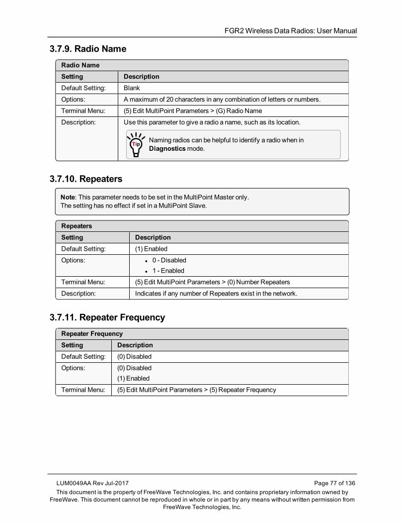
FGR2WirelessData Radios: User Manual
3.7.9. Radio NameRadio NameSetting DescriptionDefault Setting: Blank
Options: A maximum of 20 characters in any combination of letters or numbers.
Terminal Menu: (5) Edit MultiPoint Parameters > (G) Radio Name
Description: Use this parameter to give a radio a name, such as its location.
Naming radios can be helpful to identify a radio when inDiagnosticsmode.
3.7.10. Repeaters
Note: This parameter needs to be set in theMultiPoint Master only.The setting has no effect if set in aMultiPoint Slave.
RepeatersSetting DescriptionDefault Setting: (1) Enabled
Options: l 0 - Disabledl 1 - Enabled
Terminal Menu: (5) Edit MultiPoint Parameters > (0) Number Repeaters
Description: Indicates if any number of Repeaters exist in the network.
3.7.11. Repeater FrequencyRepeater FrequencySetting DescriptionDefault Setting: (0) Disabled
Options: (0) Disabled(1) Enabled
Terminal Menu: (5) Edit MultiPoint Parameters > (5) Repeater Frequency
LUM0049AA Rev Jul-2017 Page 77 of 136This document is the property of FreeWave Technologies, Inc. and contains proprietary information owned by
FreeWave. This document cannot be reproduced in whole or in part by any means without written permission fromFreeWave Technologies, Inc.
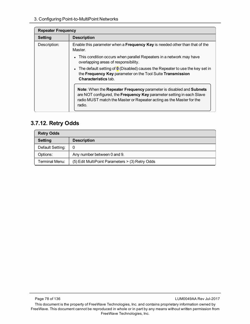
3. Configuring Point-to-MultiPoint Networks
Page 78 of 136 LUM0049AA Rev Jul-2017This document is the property of FreeWave Technologies, Inc. and contains proprietary information owned by
FreeWave. This document cannot be reproduced in whole or in part by any means without written permission fromFreeWave Technologies, Inc.
Repeater FrequencySetting DescriptionDescription: Enable this parameter when a Frequency Key is needed other than that of the
Master.
l This condition occurs when parallel Repeaters in a network may haveoverlapping areas of responsibility.
l The default setting of 0 (Disabled) causes the Repeater to use the key set inthe Frequency Key parameter on the Tool Suite TransmissionCharacteristics tab.
Note: When theRepeater Frequency parameter is disabled andSubnetsare NOT configured, the Frequency Key parameter setting in each SlaveradioMUSTmatch theMaster or Repeater acting as theMaster for theradio.
3.7.12. Retry OddsRetry OddsSetting DescriptionDefault Setting: 0
Options: Any number between 0 and 9.
Terminal Menu: (5) Edit MultiPoint Parameters > (3) Retry Odds
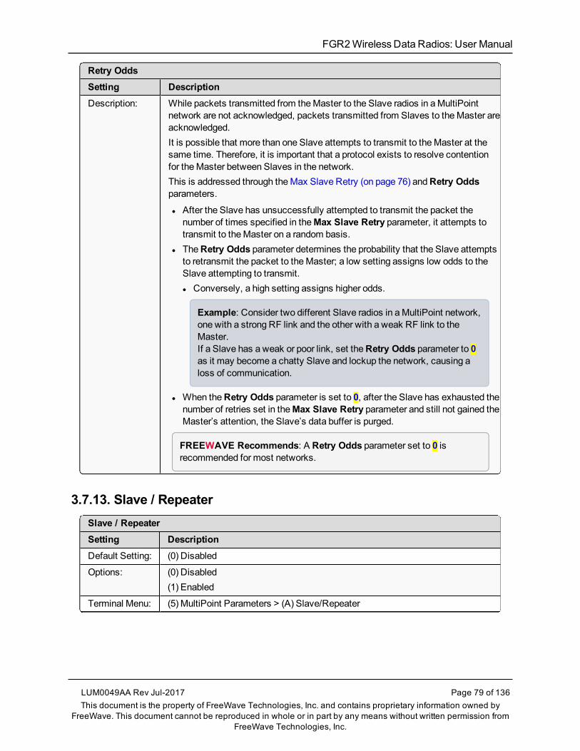
FGR2WirelessData Radios: User Manual
Retry OddsSetting DescriptionDescription: While packets transmitted from theMaster to the Slave radios in aMultiPoint
network are not acknowledged, packets transmitted from Slaves to theMaster areacknowledged.It is possible that more than one Slave attempts to transmit to theMaster at thesame time. Therefore, it is important that a protocol exists to resolve contentionfor theMaster between Slaves in the network.This is addressed through theMax Slave Retry (on page 76) andRetry Oddsparameters.
l After the Slave has unsuccessfully attempted to transmit the packet thenumber of times specified in theMax Slave Retry parameter, it attempts totransmit to theMaster on a random basis.
l TheRetry Odds parameter determines the probability that the Slave attemptsto retransmit the packet to theMaster; a low setting assigns low odds to theSlave attempting to transmit.l Conversely, a high setting assigns higher odds.
Example: Consider two different Slave radios in aMultiPoint network,one with a strong RF link and the other with a weak RF link to theMaster.If a Slave has a weak or poor link, set theRetry Odds parameter to 0as it may become a chatty Slave and lockup the network, causing aloss of communication.
l When theRetry Odds parameter is set to 0, after the Slave has exhausted thenumber of retries set in theMax Slave Retry parameter and still not gained theMaster’s attention, the Slave’s data buffer is purged.
FREEWAVE Recommends: A Retry Odds parameter set to 0 isrecommended for most networks.
3.7.13. Slave / RepeaterSlave / RepeaterSetting DescriptionDefault Setting: (0) Disabled
Options: (0) Disabled(1) Enabled
Terminal Menu: (5) MultiPoint Parameters > (A) Slave/Repeater
LUM0049AA Rev Jul-2017 Page 79 of 136This document is the property of FreeWave Technologies, Inc. and contains proprietary information owned by
FreeWave. This document cannot be reproduced in whole or in part by any means without written permission fromFreeWave Technologies, Inc.

3. Configuring Point-to-MultiPoint Networks
Page 80 of 136 LUM0049AA Rev Jul-2017This document is the property of FreeWave Technologies, Inc. and contains proprietary information owned by
FreeWave. This document cannot be reproduced in whole or in part by any means without written permission fromFreeWave Technologies, Inc.
Slave / RepeaterSetting DescriptionDescription: TheSlave/Repeatermode allows a radio in aMultiPoint network to switch
between Slave and Repeater functions.
l When in this mode, a radio repeats any packets sent across the network aswell as uses the data port.
l Thus, where one Repeater and one Slavemay be required in another vendor’snetwork, FreeWave networks require only one radio.
To operate a radio as aMultiPoint Slave/Repeater, these parameters must be set:l TheModem Mode parameter in theOperation Mode tabmust be set toMultiPoint Repeater.
l TheSlave/Repeater parameter in theMultiPoint Parameters tabmust beenabled.
3.8. Conserving PowerPower consumption can be essential, especially for remote sites that are difficult to access. Usethese options on the Transmission Characteristics tab to conserve power.These settings are available in theRadio Transmission Characteristicsmenu in the terminalinterface.
l Low Power Mode - Available in MultiPoint Slaves.l Conserves power primarily by dimming the radio's LEDs.
Note: For more information, see Low PowerMode (on page 80).
l Remote LEDs - If the radio has the optional 20-in connector, use this option to connectremote LEDs through the diagnostics port.
This featuremay be used to save power in MultiPoint Repeaters where the otheroptions are not available.
Note: For more information, see Remote LED (on page 52).
3.8.1. Low Power Mode
Important!: This setting applies only to MultiPoint Slave radios.Low Power Mode does not work with MultiPoint Repeaters because they are constantlytransmitting.

FGR2WirelessData Radios: User Manual
Low Power ModeSetting DescriptionDefault Setting: 0
Options: l Any number between 0 and 31.l The higher the number, the greater the power consumption decrease.
Terminal Menu: (3) Edit Radio Transmission Characteristics > (9) Low PowerMode
Description: Allows aMultiPoint Slave radio to consume less power, primarily by dimming theradio's LEDs.When set to 2 through 31, the radio sleeps between slots.
Example: Using a setting of 2 the radio sleeps 1 out of 2 slots.Using a setting of 3 the radio sleeps 2 out of 3 slots, etc.
When the radio is asleep, it hears nothing from theMaster.This table shows the changes at different Low Power Mode settings.l The actual current draw depends onmany factors.l The table gives only a qualitative indication of supply current savings.l A low number reduces latency and a high number reduces currentconsumption.
Setting Description0 Low power, disabled.
1 l LEDs dimmed, radio remains awake.l Radio is listening to theMaster’stransmissions on every slot.
l Radio’s data port is shut down if theRTS line is de-asserted (low).
l In this case, the radio needs to beawakened before it is able to send datato theMaster.
2 LEDs dimmed, radio sleeps every otherslot.
3 LEDs dimmed, radio sleeps 2 of 3 slots.
4-31 LEDs dimmed, radio sleeps the number ofslots corresponding to the setting.
Example: With a setting of 31 theradio sleeps 30 of 31 slots.
LUM0049AA Rev Jul-2017 Page 81 of 136This document is the property of FreeWave Technologies, Inc. and contains proprietary information owned by
FreeWave. This document cannot be reproduced in whole or in part by any means without written permission fromFreeWave Technologies, Inc.

3. Configuring Point-to-MultiPoint Networks
Page 82 of 136 LUM0049AA Rev Jul-2017This document is the property of FreeWave Technologies, Inc. and contains proprietary information owned by
FreeWave. This document cannot be reproduced in whole or in part by any means without written permission fromFreeWave Technologies, Inc.
Low Power ModeSetting Description
Notesl Power savings occur only when the Slave radio is linked.
l No power savings occur when the Slave radio is transmitting data.l Low Power Mode is of little value when a Slave has a constant, highthroughput.
l TheMCU Speed parameter MUST be set to 0 and theRF Data Rateparameter MUST be set to 3 for Low Power Mode to operate properly.
l To communicate to an RS-232 port of a radio that is in Low Power Mode, theRTS lineMUST be held high to wake it up.l The radio wakes up within approximately 20milliseconds of when RTSgoes high.
l If the Request to Send (RTS) line on the Slave radio is held high, the radioremains in normal operation regardless of the Low Power Mode setting.
l After RTS is dropped the radio reverts to the Low Power Mode.l If the radio has the DTR Connect (on page 73) parameter in theMultiPointParameters tab set to 1 or 2 and if the Low Power Mode is enabled (set to 1to 31), the RTS line on the radioMUST be asserted for theDTR Connectfeature to operate properly.
l The diagnostic pins MUST be disabled or terminated to a cable for the sleepcurrent in Lower Power Mode to match the specifications.l To disable the diagnostic pins, set these options:
l In theBaud Rate tab, the Setup Port (on page 36) parameter is set to 1(Main Only).
l In theMultiPoint Parameters tab, the Diagnostics (on page 73)parameter is set to 0 (Off).
3.9. Reading Diagnostics in Tool SuiteTheNetwork Diagnostics application provides a place to view diagnostic data for all the devicesconnected to theMaster in the network in real time.
Important!: TheNetwork Diagnostics application is NOTmeant to replicate the functionality of aNetwork Management System.It is a tool intended for occasional network monitoring or troubleshooting in the field, not forcontinuous, long-term collection of diagnostic data.
This section provides basic steps for reading diagnostics using Tool Suite. Tool Suite stores thediagnostic data in the database for import from or export to a diagnostic file.For information regarding the data available, recommended best practices, and importing andexporting files using theNetwork Diagnostics application, see the Tool Suite User Manualavailable in the Tool Suite software.

FGR2WirelessData Radios: User Manual
To help identify the radios in the network when runningNetwork Diagnostics, set theRadioName andRadio ID fields on theMultiPoint Parameters tab.
The diagnostic programmust be run from theMaster radio. Diagnostics require:l A setting between 1 and 128 in theDiagnostics parameter available in theMultiPointParametersmenu on theMaster.
l A second computer or serial connection to run the diagnostics software.l A diagnostics cable. (Available from FreeWave.)l Diagnostics software. (Available fromwww.freewave.com).
Note: For more information about diagnostics, contact FreeWave Technical Support.See Contact FreeWave Technical Support (on page 9).
Procedure1. Connect theMaster to the computer running Tool Suite.2. Open Tool Suite.3. On the Applications tab, clickNetwork Diagnostics.4. In theNetworks section of the ribbon, use the list box to select the serial network to run
diagnostics on.If there is no network defined, clickAdd and follow the instructions in the wizard.
5. On the ribbon, clickStart.6. To stop running diagnostics, clickStop.
Note: TheNetwork Diagnostics application continues to poll for diagnostic data until it is stopped.
Important!: Tool Suite is NOT optimized for the collection andmanagement of large amounts ofdiagnostic data from continuous polling.Collection of excessive amounts of data results in overall performance degradation in Tool Suite andnetwork throughput degradation.
LUM0049AA Rev Jul-2017 Page 83 of 136This document is the property of FreeWave Technologies, Inc. and contains proprietary information owned by
FreeWave. This document cannot be reproduced in whole or in part by any means without written permission fromFreeWave Technologies, Inc.

FGR2WirelessData Radios: User Manual
4. ConfiguringPoint-to-Point Networks
Point-to-Point networks are themost basic type of network and do not requiremuchmore thanthe setup described in the basic programming and setup section.This section provides:
l A brief quick start to setup a Point-to-Point network.l An LED chart for LED function within a Point-to-Point network.l Information about programming the Call Book.
4.1. Point-to-Point Network Quick StartTo establish a link between a pair of FreeWave radios just received from the factory, completethese steps for each radio.
4.1.1. Point-to-Point Network Quick Start (Tool Suite)1. Connect the radio to the serial port of a computer either through a serial cable or via the
diagnostics cable.2. Connect the radio to a power source.
Note: Power supply ranges and recommendations vary depending onmodel.Verify the specifications for themodel you are using prior to connecting power.
3. Open a Tool Suite session.4. Click theConfiguration application.5. Verify the correct port is selected in theCom Port field in theConfiguration ribbon.6. On theConfiguration ribbon, in theNetworks section, select the network the radio
resides in or clickAdd Network to create a new network in Tool Suite.
LUM0049AA Rev Jul-2017 Page 84 of 136This document is the property of FreeWave Technologies, Inc. and contains proprietary information owned by
FreeWave. This document cannot be reproduced in whole or in part by any means without written permission fromFreeWave Technologies, Inc.

4. Configuring Point-to-Point Networks
Page 85 of 136 LUM0049AA Rev Jul-2017This document is the property of FreeWave Technologies, Inc. and contains proprietary information owned by
FreeWave. This document cannot be reproduced in whole or in part by any means without written permission fromFreeWave Technologies, Inc.
7. ClickRead Radio on theConfiguration ribbon to read the radio's current settings.l If using a diagnostics cable to connect to the radio, the radio automatically goes intoSetupmode.
l If using a data cable to connect to the radio, a prompt appears to press the radio'sSetup button to enter Setupmode.
l When inSetupmode, all three LEDs on the radio display solid green .8. Click theOperation Mode tab.9. In theModem Mode field, select to set the radio to Point-to-Point mode.
Example: Set one radio as a Point-to-Point Master (Mode 0) and the other as a Point-to-PointSlave (Mode 1).
Note: A Point-to-Point network can have only oneMaster.For more information about modemmodes, see Setting the Radio's Role in the Network andthe Network Type (on page 30).
10. Click theBaud Rate tab.11. Change theBaud Rate,Data Parity, andModbus RTU to match the device that the radio
is to be attached to.12. Click the Transmission Characteristics tab.13. Set these parameters so they are identical on all radios in the network:
l Frequency Keyl MaxPacket Sizel Min Packet Sizel RFData RateIf several independent networks are located in close proximity, it becomes veryimportant to include asmuch frequency and time diversity as possible through use ofdifferent Frequency Key,Min and Max Packet Size, andHop Table parametersettings.
14. Click the Call Book tab.15. Enter the Slave serial number in theMaster’s Call Book.16. Enter theMaster’s Serial number in the Slave’s Call Book, or disable theSlave Security
parameter in the Slave.
Note: For more information about setting up the Call Book see Using the Call Book in Point-to-Point Networks (on page 89).
Shortly after both radios are plugged in, they should establish a link with each other and theconnection is complete.
17. Using the Point-to-Point Operation LEDs (on page 88), verify that the radios are operatingas expected.
18. On theConfiguration application in theNetwork Title ribbon:

FGR2WirelessData Radios: User Manual
l ClickAll to send all the settings for all parameters.l ClickQuick to send only the changed parameters.
Note: Quick is only available if Read Radio is selected and parameter settings areNOT sent from a template to the radio.
4.1.2. Point-to-Point Network Quick Start (Terminal Interface)1. Connect the radio to the serial port of a computer either through a serial cable or via the
diagnostics cable.2. Connect the radio to a power source.
Note: Power supply ranges and recommendations vary depending onmodel.Verify the specifications for themodel you are using prior to connecting power.
3. Open a terminal emulator session.
Note: Use theSetup Terminal application in Tool Suite if a terminal emulator is unavailable.
4. Connect to COMx (where 'x' is the number of the COMport being connected).5. Set these parameters to:
l Data Rate - 19,200l Data Bits - 8l Parity - nonel Stop bits - 1l Flow Control - none
6. Press theSetup button on the radio.If using the diagnostics cable, press <Shift+U>.l When inSetupmode, all three LEDs on the radio display solid green .l TheMain Menu appears in the window.
7. Type 0 and (missing or bad snippet) to access theOperation Modemenu.8. Type 0 and (missing or bad snippet) to set the radio as a Point-to-Point Masteror
Type 1 and (missing or bad snippet) to set the radio as Point-to-Point Slave.
Note: For more information about modemmodes, see Setting the Radio's Role in theNetwork and the Network Type (on page 30).
9. Press <Esc> to return to theMainmenu.10. On theMain Menu, type 1 and (missing or bad snippet).11. Change theBaud Rate,Data Parity, andModbus RTU to match the device that the radio
is to be attached to.12. Press <Esc> to return to theMainmenu.13. On theMain Menu, type 2 and (missing or bad snippet) to update the Call Book.14. Enter the Slave serial number in theMaster’s Call Book.
LUM0049AA Rev Jul-2017 Page 86 of 136This document is the property of FreeWave Technologies, Inc. and contains proprietary information owned by
FreeWave. This document cannot be reproduced in whole or in part by any means without written permission fromFreeWave Technologies, Inc.

4. Configuring Point-to-Point Networks
Page 87 of 136 LUM0049AA Rev Jul-2017This document is the property of FreeWave Technologies, Inc. and contains proprietary information owned by
FreeWave. This document cannot be reproduced in whole or in part by any means without written permission fromFreeWave Technologies, Inc.
15. Enter theMaster’s Serial number in the Slave’s Call Book ordisable the Slave Security (on page 56) parameter in the Slave.
Note: For more information about setting up the Call Book see Using the Call Book in Point-to-Point Networks (on page 89).
16. On theMain Menu, type 3 and (missing or bad snippet).17.18. Press <3> on theMainmenu.19. Set these parameters so they are identical on all radios in the network:
l Frequency Keyl MaxPacket Sizel Min Packet Sizel RFData Rate
Note: The Frequency Key option is located in the F submenu after you press <0> to accessthe Frequency Keymenu onMainmenu <3>.
20. Press <Esc> to return to theMainmenu.Shortly after both radios are plugged in, they should establish a link with each other and theconnection is complete.
21. Using the Point-to-Point Operation LEDs (on page 88), verify that the radios are operatingas expected.
22. Press <Esc> to exit theSetupmenu and resume normal radio operation.

FGR2WirelessData Radios
4.2. Point-to-Point Operation LEDsMaster Slave Repeater
ConditionCarrierDetect(CD)
Transmit(Tx)
Clear toSend(CTS)
CarrierDetect(CD)
Transmit(Tx)
Clear toSend(CTS)
CarrierDetect(CD)
Transmit(Tx)
Clear toSend(CTS)
Powered, no link Solid redbright
Solid redbright
Solid redbright
Solid redbright
Off Blinkingred
Solid redbright
Off Blinkingred
Linked.
No Repeater
Sending sparse data
Solidgreen
Intermittent flash red Intermittentflash red
Solidgreen
Intermittentflash red
Intermittentflash red
N/A N/A N/A
Master calling
Slave through Repeater
Solid redbright
Solid reddim
Solid redbright
Solid redbright
Off Blinkingred
Solid redbright
Off Blinkingred
Master linked to Repeater,not to Slave
Flashing orange Solid reddim
Solid redbright
Solid redbright
Off Blinkingred
SolidRedbright
Solid reddim
Solid redbright
Repeater linked to Slave Solidgreen
Intermittentflash red
Intermittentflash red
Solidgreen
Intermittentflash red
Intermittentflash red
Solidgreen
Intermittentflash red
Intermittentflash red
Mode 6
Waiting for ATD command
Solid redbright
Off Blinkingred
Solid redbright
Off Blinkingred
N/A N/A N/A
SetupMode Solidgreen
Solidgreen
Solidgreen
Solidgreen
Solidgreen
Solidgreen
Solidgreen
Solidgreen
Solidgreen
LUM0049AA Rev Jul-2017 Page 88 of 136This document is the property of FreeWave Technologies, Inc. and contains proprietary information owned by FreeWave. This document cannot be reproduced
in whole or in part by any means without written permission from FreeWave Technologies, Inc.

4. Configuring Point-to-Point Networks
Page 89 of 136 LUM0049AA Rev Jul-2017This document is the property of FreeWave Technologies, Inc. and contains proprietary information owned by
FreeWave. This document cannot be reproduced in whole or in part by any means without written permission fromFreeWave Technologies, Inc.
4.3. Using the Call Book in Point-to-Point NetworksUsing the Call Book offers both security and flexibility in determining how FreeWave radioscommunicate with each other.
Important!: The Call Book is required in Point-to-Point networks.
FREEWAVE Recommends: While the Call Book is an option in Point-to-MultiPoint networks,FreeWave strongly recommends using theNetwork ID feature in most applications.If a largeMultiPoint network is implemented using the Call Book and a radio needs to be added to orreplaced in the network, each radio in the network must be physically reprogrammed and the newserial number entered in the radio's Call Book.This can be a time consuming process and can cause a delay in getting the network back up andrunning.Because theNetwork ID does not use serial numbers, MultiPoint Master radios and Repeaters maybe added or replaced without reprogramming each Slave radio in the network.
l TheCall Book allows amaximumof 10 FreeWave radios.l Designate 1 to 4 Repeaters to use with each radio.l Designate which Slave theMaster calls.
These settings are required for two FreeWave radios to communicate in Point-to-Point mode:1. TheMaster radio serial number must be listed in the Slave radio's Call Book or Slave
Security is turned off in the Slave.2. The Slave serial number must be listed in theMaster Call Book .3. TheMaster must be programmed to call the Slave (Entry to Call option).
a. Select the number in theEntry to Call field, selectAll to direct theMaster to call allSlave radios.
Note: To set theEntry to Call option in the terminal interface, press <C> at the Call Bookmenu, followed by themenu number corresponding to that Slave.To call any available Slave in the list, press <C> then press <A> to direct theMaster toCallAll.
It is important that the Call Book slots (0-9) are filled sequentially starting with slot 0.l When aMaster is instructed toCall All, it calls all Slave radios listed until it reaches the firstserial number of 000-0000 (or a blank slot).
l If a serial number is entered after the all zero number or as a Repeater, theMaster does notrecognize it as a valid number.
Note: When entering numbers into the Call Book, define only the Repeaters in theMaster's CallBook.The Slave's Call Book only requires theMaster serial number.A Repeater need not have anything listed in its Call Book.

FGR2WirelessData Radios: User Manual
4.3.1. Setting the Call Book in Tool Suite1. In the Tool SuiteConfiguration application, select the device to program.2. Click the (2) Call Book tab.3. In theNumber column inRow 0, enter the seven-digit serial number of the radio being
called.4. In theRepeater 1 column, enter the first Repeater's seven-digit number.
If no Repeaters are being used, leave the column empty.5. In theRepeater 2 column, enter the second Repeater’s 7-digit number.
If only one Repeater is being used, leave the column empty.6. If Repeaters are being used, select the appropriateEntry to Call option in theMaster Call
Book.7. To apply the changes, click either theQuick orAll icon.
Tool Suite applies the changes to the radio.
LUM0049AA Rev Jul-2017 Page 90 of 136This document is the property of FreeWave Technologies, Inc. and contains proprietary information owned by
FreeWave. This document cannot be reproduced in whole or in part by any means without written permission fromFreeWave Technologies, Inc.

4. Configuring Point-to-Point Networks
Page 91 of 136 LUM0049AA Rev Jul-2017This document is the property of FreeWave Technologies, Inc. and contains proprietary information owned by
FreeWave. This document cannot be reproduced in whole or in part by any means without written permission fromFreeWave Technologies, Inc.
4.3.2. Setting the Call Book in the Terminal Interface1. On theSetupmenu, clickC(2) Edit all Book.
TheModem Call Bookwindow opens.
Figure 23: Modem Call Book window
2. Enter the number or letter associated with the option to select.3. In theEnter New Number prompt, enter the seven-digit serial number of the radio being
called.The system prompts for the first Repeater's serial number.
4. If no Repeaters are being used, press <Esc> and continue.Otherwise, enter the 7-digit serial number of the Repeater.The system prompts for the second Repeater's serial number.
5. Enter the 7-digit serial number of the second Repeater.If only one Repeater is being used, press <Esc>.The system refreshes the radio’sCall Bookmenuwith the new changes.
6. Repeat steps 2 to 5 for additional radios in the network.7. Press <Esc> to return to theMainmenu.

FGR2WirelessData Radios: User Manual
4.3.3. Programming Point-To-Point Extended Call Book to Use Three orFour RepeatersIn a Point-to-Point configuration, FreeWave radios can use amaximumof four Repeaters.
1. To use three or four Repeaters, program the Call Bookwith the Slave serial number,followed by the first two Repeaters.
2. On the next line enter 999-9999 as the radio to call.3. When prompted for the Repeaters enter the third and fourth Repeaters in the link.
Figure 24 shows a Point-to-Point link where a Slave is called through four Repeaters. In thisexample:
l theMaster is calling the Slave, 571-3872, through Repeater 1, 901-1234,l then Repeater 2,910-0234,l then Repeater 3, 571-3456, and finallyl Repeater 4, 571-4567.
l Entering the serial number 999-9999 in line 1 instructs theMaster to continue callingthrough the Repeaters programmed on that line.
Figure 24: Point-to-Point link where a Slave is called through four Repeaters
l To call a Slave radio through one or more Repeaters, that Slavemust be called individually.l WithCall All selected, theMaster will not connect with any Slave radios throughRepeaters.
l TheMaster calls every Slave in the list and connects with the first Slave that responds.l When calling through a Repeater, theMaster must first call that Repeater and establish acommunications link with it prior to making contact with the Slave.
LUM0049AA Rev Jul-2017 Page 92 of 136This document is the property of FreeWave Technologies, Inc. and contains proprietary information owned by
FreeWave. This document cannot be reproduced in whole or in part by any means without written permission fromFreeWave Technologies, Inc.

FGR2WirelessData Radios: User Manual
5. Advanced Programming
The settings and scenarios covered in this section are considered advanced programming.l Working with Parallel Repeaters (on page 94)l Setting and Changing Radio Passwords (on page 96)l Enable and Set Up AES Encryption (on page 97)
l Encryption Channel Key (on page 98)l Encryption Key (on page 98)l Encryption (Strength) (on page 100)l Troubleshooting AES Setup (on page 100)
l Low BaudRates (on page 101)l Multi-Master Sync (on page 101)l TimeDivisible Multiple Access (TDMA) (on page 101)
LUM0049AA Rev Jul-2017 Page 93 of 136This document is the property of FreeWave Technologies, Inc. and contains proprietary information owned by
FreeWave. This document cannot be reproduced in whole or in part by any means without written permission fromFreeWave Technologies, Inc.

5. Advanced Programming
Page 94 of 136 LUM0049AA Rev Jul-2017This document is the property of FreeWave Technologies, Inc. and contains proprietary information owned by
FreeWave. This document cannot be reproduced in whole or in part by any means without written permission fromFreeWave Technologies, Inc.
5.1. Working with Parallel RepeatersWhenRepeaters are added to a network, plan accordingly to avoid creating a parallel Repeaterscenario. A parallel Repeater is defined as two or more Repeaters linked to the same point in thenetwork.
l Repeaters Data Transmitted on the Same Frequency Key (on page 94)l Adding a Repeater to the Network (on page 95)
5.1.1. Repeaters Data Transmitted on the Same Frequency KeyIn this diagram, the Slave radio in themiddle has overlapping coverage from both the Repeaters(parallel Repeaters). Data from the Repeaters is transmitted on the same Frequency Key in thesame time slot, which createsmessage collisions.
Figure 25: Slave Radio with Overlapping Coverage
To resolve this scenario, change these settings on one or more of the Repeaters in conflict:
Settings to Change on Repeaters in ConflictSetting DescriptionRepeaterFrequency
l Set theRepeater Frequency parameter in theMultiPoint Parameters tab toany number other than 0.
l If set to a number other than 0, the radio uses the frequency key set in theFrequency Key parameter in the Transmission Characteristics tab, insteadof the frequency key assigned to theMaster.
Frequency Key Set the Frequency Key parameter in the Transmission Characteristics tab to akey other than that of the conflicting Repeater.
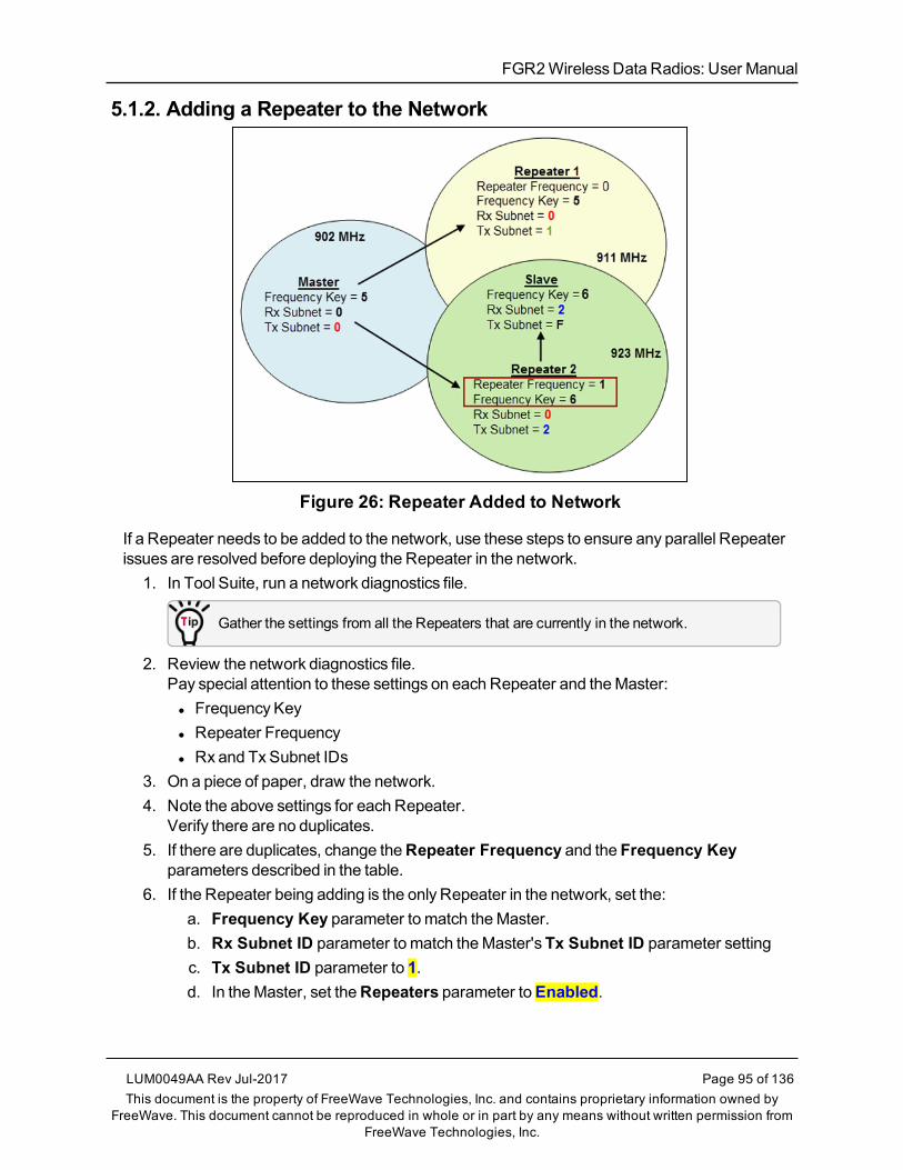
FGR2WirelessData Radios: User Manual
5.1.2. Adding a Repeater to the Network
Figure 26: Repeater Added to Network
If a Repeater needs to be added to the network, use these steps to ensure any parallel Repeaterissues are resolved before deploying the Repeater in the network.
1. In Tool Suite, run a network diagnostics file.
Gather the settings from all the Repeaters that are currently in the network.
2. Review the network diagnostics file.Pay special attention to these settings on each Repeater and theMaster:l Frequency Keyl Repeater Frequencyl Rx and Tx Subnet IDs
3. On a piece of paper, draw the network.4. Note the above settings for each Repeater.
Verify there are no duplicates.5. If there are duplicates, change theRepeater Frequency and the Frequency Key
parameters described in the table.6. If the Repeater being adding is the only Repeater in the network, set the:
a. Frequency Key parameter to match theMaster.b. Rx Subnet ID parameter to match theMaster'sTx Subnet ID parameter settingc. Tx Subnet ID parameter to 1.d. In theMaster, set theRepeaters parameter toEnabled.
LUM0049AA Rev Jul-2017 Page 95 of 136This document is the property of FreeWave Technologies, Inc. and contains proprietary information owned by
FreeWave. This document cannot be reproduced in whole or in part by any means without written permission fromFreeWave Technologies, Inc.

5. Advanced Programming
Page 96 of 136 LUM0049AA Rev Jul-2017This document is the property of FreeWave Technologies, Inc. and contains proprietary information owned by
FreeWave. This document cannot be reproduced in whole or in part by any means without written permission fromFreeWave Technologies, Inc.
5.2. Setting and Changing Radio PasswordsUse passwords to prevent access to or changing of any of the radio’s parameters. This option isuseful to prevent unauthorized personnel from gaining access to the radio settings.
Note: If theSetup Port option on theBaud Rate tab is set to (1) Main Only or (3) Both, thepassword is only accepted if the option is accessed from themain data port.To use the Password function using the diagnostics port, theSetup Port optionmust be set to (2)Diagnostics Only.
Warning! If the password feature is enabled and the password is forgotten, the radio MUST bereturned to FreeWave to have the password disabled.
5.2.1. Setting the Password1. On theSetupmenu in the terminal interface, select (8) Chg Password.
New PW? (<esc> to exit) appears.
Note: Press <Esc> to cancel the process at any time.
2. Enter exactly four characters.Passwords are case sensitive.<Enter> to accept,<esc> to quit appears.
3. Press <Enter> to accept the password and enable the feature.Press <Esc> to quit the process and not enable the password.
Important!: Press <Enter> and the password appears on the line above.The password is case sensitive and every keystroke is a character.
5.2.2. Changing a PasswordAfter the password feature has been enabled, it is possible to change to a new password.
1. On theSetupmenu in the terminal interface, select (8) Chg Password.TheEnter Security Code prompt appears.
2. Enter the current four character, case-sensitive password.The prompt to enter the new password appears.
3. Re-enter the new four character, case-sensitive password.
Note: Press <Esc> to cancel the process at any time.
4. Press <Enter> to accept the password and enable the feature.Press <Esc> to quit the process and not enable the password.
Important!: Press <Enter> and the password appears on the line above.The password is case sensitive and every keystroke is a character.

FGR2WirelessData Radios: User Manual
5.2.3. Disable a PasswordAfter the password features has been enabled, it is possible to disable the password if thecurrent password is known.
Important!: The password can only be disabled using the prompt when reading the radio in ToolSuite or through a terminal emulator.The password CANNOT be disabled usingSetup Terminal application in Tool Suite.
1. On theSetupmenu in the terminal interface, select (8) Chg Password.2. Hold down the <Alt> key and type 0255 using the number pad on the keyboard.3. Release the <Alt> key.4. Repeat this step threemore times (hold <Alt> and type 0255 a total of 4 times).
Important!: Type the 0255 using the NUM Pad on the keyboard, NOT the top row ofnumerals.
5. After the fourth entry, the password is disabled.
5.3. Enable and Set Up AES EncryptionProtecting the confidentiality, integrity, and authenticity of data communications is essential tomaintaining a robust, reliable, and secure wireless infrastructure. FreeWave has incorporated anumber of mechanisms to achieve these critical security objectives, including the use of AESencryption.When available and enabled, AES encryption adds a layer of 128-bit, 192-bit, or 256-bit encryption strength to the data before it is sent over the RF link.
Note: AES encryption is available as an option set at the factory in firmware v10.6.6 and later insome FGR2models.
When using AES encryption, these settings are required:l Encryption Channel Key (on page 98).l Encryption Key (on page 98).l Encryption (Strength) (on page 100).
Important!: These settings are ONLY available in the (3) Edit Radio TransmissionCharacteristics > (E) Encryptionmenu in the terminal interface.These settings are NOT available in Tool Suite.
Note: For information about accessing theSetupmenu using the terminal interface, see Access theSetupMenu Using a Terminal Emulator (on page 23).
Important!: When AES is enabled, every radio in the network must havematching encryptionstrengths, encryption keys, and encryption channel keys, and theMCU Speed parameter set to 3 forsuccessful communication and data transmission.
LUM0049AA Rev Jul-2017 Page 97 of 136This document is the property of FreeWave Technologies, Inc. and contains proprietary information owned by
FreeWave. This document cannot be reproduced in whole or in part by any means without written permission fromFreeWave Technologies, Inc.
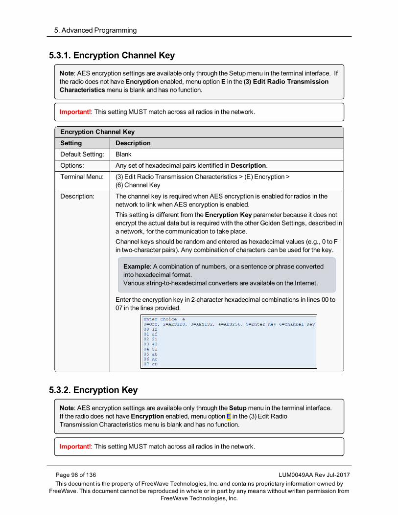
5. Advanced Programming
Page 98 of 136 LUM0049AA Rev Jul-2017This document is the property of FreeWave Technologies, Inc. and contains proprietary information owned by
FreeWave. This document cannot be reproduced in whole or in part by any means without written permission fromFreeWave Technologies, Inc.
5.3.1. Encryption Channel Key
Note: AES encryption settings are available only through the Setupmenu in the terminal interface. Ifthe radio does not haveEncryption enabled, menu optionE in the (3) Edit Radio TransmissionCharacteristicsmenu is blank and has no function.
Important!: This settingMUSTmatch across all radios in the network.
Encryption Channel KeySetting DescriptionDefault Setting: Blank
Options: Any set of hexadecimal pairs identified inDescription.Terminal Menu: (3) Edit Radio Transmission Characteristics > (E) Encryption >
(6) Channel Key
Description: The channel key is required when AES encryption is enabled for radios in thenetwork to link when AES encryption is enabled.This setting is different from theEncryption Key parameter because it does notencrypt the actual data but is required with the other Golden Settings, described ina network, for the communication to take place.Channel keys should be random and entered as hexadecimal values (e.g., 0 to Fin two-character pairs). Any combination of characters can be used for the key.
Example: A combination of numbers, or a sentence or phrase convertedinto hexadecimal format.Various string-to-hexadecimal converters are available on the Internet.
Enter the encryption key in 2-character hexadecimal combinations in lines 00 to07 in the lines provided.
5.3.2. Encryption Key
Note: AES encryption settings are available only through theSetupmenu in the terminal interface.If the radio does not haveEncryption enabled, menu optionE in the (3) Edit RadioTransmission Characteristics menu is blank and has no function.
Important!: This settingMUSTmatch across all radios in the network.

FGR2WirelessData Radios: User Manual
Encryption KeySetting DescriptionDefault Setting: Blank
Options: Any set of hexadecimal pairs identified inDescription.Terminal Menu: (3) Edit Radio Transmission Characteristics > (E) Encryption >
(5) Enter Key
Description: The encryption key is the piece of information used to encrypt and un-encrypt thedata sent through the network. Even with encryption, the data is only as secure asthe strength of the encryption key used.Keys should be random and entered as hexadecimal values (i.e., 0 to F in two-character pairs). Any combination of characters can be used for the key.
Example: A combination of numbers, or a sentence or phrase convertedinto hexadecimal format.Various string-to-hexadecimal converters are available on the Internet.
Enter the encryption key in 2-character hexadecimal combinations in the linesprovided:
TheEnter Key option always asks for all 32 lines of the encryption key. However,the encryption strength you select determines how many of the lines are required:
l 128-bit encryption - Enter key information in rows 00 to 0F.l The last 16 lines (10 to 1F) are ignored.
l 192-bit encryption - Enter key information in rows 00 to 17.l The last 8 entries (18 to 1F) are ignored.
l 256-bit encryption - Enter key information in rows 00 to 1F.l All lines are used.
LUM0049AA Rev Jul-2017 Page 99 of 136This document is the property of FreeWave Technologies, Inc. and contains proprietary information owned by
FreeWave. This document cannot be reproduced in whole or in part by any means without written permission fromFreeWave Technologies, Inc.

5. Advanced Programming
Page 100 of 136 LUM0049AA Rev Jul-2017This document is the property of FreeWave Technologies, Inc. and contains proprietary information owned by
FreeWave. This document cannot be reproduced in whole or in part by any means without written permission fromFreeWave Technologies, Inc.
5.3.3. Encryption (Strength)
Note: AES encryption settings are available only through theSetupmenu in the terminal interface. Ifthe radio does not haveEncryption enabled, menu optionE in the (3) Edit RadioTransmission Characteristicsmenu is blank and has no function.
Important!: This settingMUSTmatch across all radios in the network.
Encryption (Strength)Setting DescriptionDefault Setting: (0) Off
Options: l (0) Off - Turns off AES encryption.l (2) AES 128 - Enables AES encryption, 128-bit strength.l (3) AES 192 - Enables AES encryption, 192-bit strength.l (4) AES 256 - Enables AES encryption, 256-bit strength.
The options available for selection are based on the encryption strength set at thefactory, or within the upgrade to use AES completed with FreeWave technicalsupport's assistance.
Example: If the radio is factory set to include AES 256, then each strengthoption is available.However, if the radio is factory set to include AES 192, then only Off, AES128, andAES 192 are available.
Note: Selecting any option other than 0 enables AES encryption.The encryption key and the channel key are required for successfulcommunication.
Terminal Menu: (3) Edit Radio Transmission Characteristics > (E) Encryption
Description: AES encryption is available in various strengths.
l The network and the data being sent determine the encryption strength used.l The higher the encryption strength, the stronger the encryption although it canalso take longer for the encryption and un-encryption to take place.
5.3.4. Troubleshooting AES SetupThe radios link, transmit data, and then unlink.
l Verify that theMCU Speed parameter is set to 3 in the terminal interface.
The radios link, transmit data, but the data is in unrecognizable characters.l Verify that theEncryption Key on each radio is set exactly the same. If the keys do notmatch, the radios can still transmit data, but cannot decrypt the data.

FGR2WirelessData Radios: User Manual
The radios do not link and the golden settings are all set the same.l Verify that theChannel Key in the Encryptionmenu is set the same across the radios in thenetwork. If the keys do not match, the radios will not link when AES is enabled, even if thegolden settingsmatch.
5.4. Low Baud RatesThe radio's Baud Ratemay be set to 300, 600, or 900.
Note: For more information about using a low baud rate, Contact FreeWave Technical Support (onpage 9).
5.5. Multi-Master SyncTheMulti-Master Sync setting is reserved for applications in both Point-to-Point andMultiPointmodeswith concentrations of Master units where it is necessary to reduce interference betweentheMaster radios.
l For more information about usingMulti-Master Sync in non-TDMAmode, seeApplication Note #5412, Synchronizing Collocated Masters.
Note: For more information about usingMulti-Master Syncwhile in TDMA mode, contact FreeWaveTechnical Support.See Contact FreeWave Technical Support (on page 9).
5.6. Time Divisible Multiple Access (TDMA)l Available as an optional, add-on feature, the FreeWave TimeDivisionMultiple Access(TDMA) protocol is an enhanced and sophisticated version of Point-to-MultiPointcommunications.
l The TDMA protocol provides timing and other parameters, which in turn allow large radionetworks to work in a non-polled environment.
Important!: This option is only used for peer-to-peer communications or when applications are verytime specific. If you purchase TDMA as an option, additional information is provided to you aboutimplementing and using the feature.
Note: For additional information about TDMA, contact FreeWave Technical Support.See Contact FreeWave Technical Support (on page 9).
LUM0049AA Rev Jul-2017 Page 101 of 136This document is the property of FreeWave Technologies, Inc. and contains proprietary information owned by
FreeWave. This document cannot be reproduced in whole or in part by any means without written permission fromFreeWave Technologies, Inc.

FGR2WirelessData Radios: User Manual
6. Viewing Radio Statistics
When reading a radio, the system shows data transmission statistics the radio has gatheredduring themost recent session. This information is valuable to know the signal strength and noiselevels of the link. Statistics are gathered during each time theMaster and Slave link and are resetwhen the next link begins.More data transmission characteristics are available, including averages gathered over time, intheNetwork Diagnostics application.
Note: For information about running network diagnostics see the Tool Suite User Manual.
l View Statistics in Tool Suite (on page 103)l View the Radio Transmission Characteristics in the Terminal Interface (on page 103)
l Antenna Reflected Power (on page 103)l Master-Slave Distance (on page 103)l Noise Level (on page 104)l Number of Disconnects (on page 104)l Radio Temperature (on page 104)l Rate% (Receive Percentage Rate) (on page 104)l Signal Level (on page 105)l Transmit Current (on page 105)
LUM0049AA Rev Jul-2017 Page 102 of 136This document is the property of FreeWave Technologies, Inc. and contains proprietary information owned by
FreeWave. This document cannot be reproduced in whole or in part by any means without written permission fromFreeWave Technologies, Inc.

6. Viewing Radio Statistics
Page 103 of 136 LUM0049AA Rev Jul-2017This document is the property of FreeWave Technologies, Inc. and contains proprietary information owned by
FreeWave. This document cannot be reproduced in whole or in part by any means without written permission fromFreeWave Technologies, Inc.
6.1. View Statistics in Tool Suite
View the same statistics using theSetup Terminal option in Tool Suite.
1. In Tool Suite, clickConfiguration > Read Radio.2. Click theDevice Information tab.
6.2. View the Radio Transmission Characteristics in theTerminal InterfaceOn theSetupmainmenu, click (4) Show Radio Statistics.
6.2.1. Antenna Reflected PowerThis is ameasurement of the transmitted power that is reflected back into the radio frommismatched antennas or cables, or loose connections between the radio and antenna.A reading of:
l 0 to 5 is good.l 5 to 20 ismarginal.l 20 or higher indicates that the connections should be inspected for loose connections andcable quality.
l 30 or higher indicates a definite problem in the system.Themost likely reason for a higherAntenna Reflected Power reading is a cable issue betweenthe radio and the antenna: loose connections, cable kinks, breaks in cable shielding, moisture inthe fittings or connections, etc.Less commonly, a highAntenna Reflected Power reading can indicate a hardware problemwith the radio itself, such as a damaged RF connector. Lastly, a high readingmay indicate aproblemwith the antenna itself, although antenna problems are the least likely indicator.
6.2.2. Master-Slave DistanceThe physical distance between the Slave radio and theMaster radio in the network.
Note: This distance is most accurate at a distance greater than 2.5miles (4.0234 km).

FGR2WirelessData Radios: User Manual
6.2.3. Noise LevelTheNoise Level indicates the level of background noise and interference at this radio and ateach of the Repeaters in the link. The number is an average of the noise levelsmeasured at eachfrequency in the radio’s frequency hop table.
The individual measurement values at each frequency hop channel are shown in the 900MHzFrequency Zones Table (on page 46).If viewing statistics in the terminal interface, press <Enter> when theRadio Statisticsmenuappears.
l Ideally, the difference between the average signal level and average noise level should be15 or more.
l Margins that are significantly higher than this are an indication of a high level of interferencethat may degrade the performance of the link.
6.2.4. Number of DisconnectsThe value in this statistic indicates the total number of times the link between theMaster and theSlave has been lost and the radios loseCarrier Detect from the time the radio is powered on untilthe radio is put intoSetupmode.
l Under ideal operating conditions, the number of disconnects should be 0.l One or more disconnectsmay indicate a weak link, the presence of severe interferenceproblems, or loss of power to any of the radios in the link.
Note: In Tool Suite, the disconnect information is available in theSummary View underNetworkDiagnostics.
6.2.5. Radio TemperatureTheRadio Temperature value is the current operating temperature of the radio in degreesCelsius.
FREEWAVE Recommends: For proper operation, a FreeWave radiomust be in the temperaturerange of -40° to +75° C.
6.2.6. Rate % (Receive Percentage Rate)TheRate %measures the percentage of data packets that were successfully transmitted from theMaster and received by the upstream radio on the first attempt. The rate percentage representsonly what the upstream radio received.
l A number of 75 or higher indicates a robust link that provides very good performance evenat high data transmission rates.
l A number of 15 or lower indicates a weak or marginal link that provides lower datathroughput.
l Throughput is reduced by 50 percent if the network contains a Repeater.
LUM0049AA Rev Jul-2017 Page 104 of 136This document is the property of FreeWave Technologies, Inc. and contains proprietary information owned by
FreeWave. This document cannot be reproduced in whole or in part by any means without written permission fromFreeWave Technologies, Inc.

6. Viewing Radio Statistics
Page 105 of 136 LUM0049AA Rev Jul-2017This document is the property of FreeWave Technologies, Inc. and contains proprietary information owned by
FreeWave. This document cannot be reproduced in whole or in part by any means without written permission fromFreeWave Technologies, Inc.
Note: Many settings can impact actual throughput, includingMaster Packet Repeat andMax SlaveRetry.If the link is asymmetrical, the percentage reported in this statistic can be very high, and the uplinkcan still be poor.
6.2.7. Signal LevelTheSignal Level indicates the level of received signal at the radio and at each of the Repeatersin the link.
l The source of the signal is the radio that transmits to the radio reading this statistic.l The number is an average of the received signal levelsmeasured at each frequency in theradio's frequency hop table.
l For a reliable link, themargin should be at least 15 dB.l Low average signal levels can often be corrected with higher gain antennas, better antennaplacement and/or additional Repeaters.
The individual measurement values at each frequency hop channel are shown in the 900MHzFrequency Zones Table (on page 46).If viewing statistics in the terminal interface, press <Enter> when theRadio Statisticsmenuappears.
6.2.8. Transmit CurrentThe Transmit Currentmeasures the current draw of the transmitter in milliamps (mA). See theradio specifications for typical values.

FGR2WirelessData Radios: User Manual
7. Approved Antennas
7.1. 900MHz Directional Antennas900MHz Directional AntennasGain(dBi) Manufacturer Manufacturer Model Number FreeWave Model Number
6 Larsen YA6-900 EAN0906YA
6 Bluewave BMY890G5502N4 EAN0906YC
10 Bluewave BMY890K5502N4 EAN0900YC
11 Larsen YA5900-W EAN0900YA
7.2. 900MHz Omni-directional Antennas900MHz Omni-directional AntennasGain(dBi) Manufacturer Manufacturer Model Number FreeWave Model Number
0 Mobile Mark PSTG0-915FW EAN0900RQ
0 Mobile Mark PSTN3-915N EAN0900NH
0 Mobile Mark PSTG0-915SE EAN0900SQ
0 Mobile Mark PSTN3-915S EAN0900SH
0 JEMA JA900SS EAN0900WR
3 Maxrad MAX-9053 EAN0900WC
5 Antennex EB8965C EAN0905WC
LUM0049AA Rev Jul-2017 Page 106 of 136This document is the property of FreeWave Technologies, Inc. and contains proprietary information owned by
FreeWave. This document cannot be reproduced in whole or in part by any means without written permission fromFreeWave Technologies, Inc.

7. Approved Antennas
Page 107 of 136 LUM0049AA Rev Jul-2017This document is the property of FreeWave Technologies, Inc. and contains proprietary information owned by
FreeWave. This document cannot be reproduced in whole or in part by any means without written permission fromFreeWave Technologies, Inc.
900MHz Omni-directional AntennasGain(dBi) Manufacturer Manufacturer Model Number FreeWave Model Number
5 Maxrad BMEFC8985HD EAN0905WC
6 Antennex FG9026 EAN0906NF

FGR2WirelessData Radios: User Manual
8. FGR2 Wireless Data Radios Pinouts
8.1. Operational RS422 and RS485 InformationFor RS-422 and RS-485, the FreeWave radio can drive 32 standard unit loads and loads the buswith only 1/8 unit load. A maximumof 256 devices can be tied on the bus if all of the line receivershave 1/8 unit load.
l RS-422 is used for 4-wire or full duplex communicationswith oneMaster radio andmultipleSlave radios.
l TheMaster radio keeps the line driver asserted at all times.l Themaximum line length is 4,000 feet using two, 120 ohm twisted pair cables with a 5thwire for data common.
An RS-485 full duplex using 4 wire plus common is the same asRS-422, except the system canhavemultiple Masters on the bus.When setting the radio to RS-485:
1. EnableModbus.2. Set theMaster Packet Repeat parameter to 3 in the radios that will use RS-485.3. Set the Turn Off Delay parameter to 4.
8.2. Pinout Assignments and Descriptionsl 20-Pin Diagnostics Connector Pinout (on page 109)l RF Board Level Pinout (on page 110)l RS-232 Pin Assignments (DB-9) (on page 111)l RS422 and RS485 Full Duplex Pinouts (on page 111)l RS485Half Duplex Pinouts (on page 112)l Waterproof Enclosure Pinout (on page 113)
LUM0049AA Rev Jul-2017 Page 108 of 136This document is the property of FreeWave Technologies, Inc. and contains proprietary information owned by
FreeWave. This document cannot be reproduced in whole or in part by any means without written permission fromFreeWave Technologies, Inc.

8. FGR2WirelessData Radios Pinouts
Page 109 of 136 LUM0049AA Rev Jul-2017This document is the property of FreeWave Technologies, Inc. and contains proprietary information owned by
FreeWave. This document cannot be reproduced in whole or in part by any means without written permission fromFreeWave Technologies, Inc.
8.3. 20-Pin Diagnostics Connector Pinout
Figure 27: 20-Pin Diagnostics Connector Pinout
Note: Pins listed with no assignment are for internal FreeWave use only.
Pin Assignment Pin Assignment1 GND 11 —
2 GDN 12 Remote Tx
3 Diag Tx 13 —
4 Diag Rx 14 —
5 — 15 Remote CTS-a
6 — 16 Remote CTS-b
7 — 17 Remote CD-a
8 — 18 Remote CD-b
9 — 19 GND
10 — 20 —

FGR2WirelessData Radios: User Manual
8.4. RF Board Level PinoutThe board-level radios are available in both TTL and RS232 versions. The TTL version usesreverse polarity from standard RS232 at 0 to 5 Volt levels. All pin descriptions and pin numberingare the same as the RS232 version. The RS232 version uses standard RS232 polarity andvoltage levels for all of the RS232 signal lines (DTR, Transmit Data, Receive Data, CarrierDetect, RTS, and Clear to Send) and TTL standard polarity and voltage level for the Interrupt pin.
l Pin 1: B+ Power input.l Pin 2: Interrupt (INT) – Input – A 0 Volt level on this pin switches the radio into Setupmode.l Pin 1 on the board-level radio is the pin farthest from the three LEDs and pin 10 is closest tothe LEDs.
Figure 28: FGR2 Pin Layout
RF Board Level Pinout
Pin Assignment Signal ACS3610xxCable Color
1 B+ input Power Red
2 Interrupt (temporarily ground to invokemenu) Input Brown
3 Data Terminal Ready (DTR) Input Orange
4 Ground Black
5 Transmit Data (TXD) Output Yellow
6 Ground Black
7 Receive Data (RXD) Input Green
8 Carrier Detect (DCD) Output Blue
9 Request to Send (RTS) Input Violet (purple)
10 Clear to Send (CTS) Output Gray
LUM0049AA Rev Jul-2017 Page 110 of 136This document is the property of FreeWave Technologies, Inc. and contains proprietary information owned by
FreeWave. This document cannot be reproduced in whole or in part by any means without written permission fromFreeWave Technologies, Inc.

8. FGR2WirelessData Radios Pinouts
Page 111 of 136 LUM0049AA Rev Jul-2017This document is the property of FreeWave Technologies, Inc. and contains proprietary information owned by
FreeWave. This document cannot be reproduced in whole or in part by any means without written permission fromFreeWave Technologies, Inc.
8.5. RS-232 Pin Assignments (DB-9)RS232 Pin Assignments (DB-9)Pin Assignment Signal Description1 CD - Carrier Detect Output Used to show anRF connection between radios.
2 TX - Transmit Data Output Used to transmit data bits serially from the radios tothe system device.
3 RX - Receive Data Input Used to receive data bits serially from the systemdevice connected to the radios.
4 DTR - Data TerminalReady
Input Used only in radios in Point-to-Point Slave/Masterswitchable mode or for DTR Connect.
5 GND -Ground Signal return for all signal lines shared with Pin 9.
6 DSR - Data Set Ready Output Always high when the radio is powered from the 2.5mm power connector. Indicates power is on to theradio. Also, this pin can be used for +12.0 Volts whenpowering the radios directly through the RS232 port.
Important!: This is not used on theOEMmodule.
7 RTS - Request to Send Input The radio does not recognize RTS for flow control.RTS is used as a control line in RTS/CTS mode.
8 CTS - Clear to Send Output This signal is used to tell the system device connectedto the radio that the radio is ready to receive data.
l When asserted, the radio accepts data, when de-asserted the radio does not accept data.
l This should always be used for data rates above38.4 KB or a risk of lost datamay occur if an RFlink is not very robust.
9 GND -Ground Signal return for all signal lines shared with Pin 5.
8.6. RS422 and RS485 Full Duplex PinoutsRS422 and RS485 Full Duplex PinoutsFunction Bare Board Pin Number DB-9 Pin NumberRX+ 7 3
RX- 9 7
TX+ 5 2
TX- 10 8
Signal Ground 4 or 6 5

FGR2WirelessData Radios: User Manual
8.7. RS485 Half Duplex PinoutsRS485 Half Duplex Pin-OutsFunction Bare Board Pin Number DB-9 Pin NumberWire to both pins for Bus + Short 5 and 7 Short 2 and 3
Wire to both pins for Bus - Short 9 and 10 Short 7 and 8
Signal Ground 4 or 6 5
LUM0049AA Rev Jul-2017 Page 112 of 136This document is the property of FreeWave Technologies, Inc. and contains proprietary information owned by
FreeWave. This document cannot be reproduced in whole or in part by any means without written permission fromFreeWave Technologies, Inc.

8. FGR2WirelessData Radios Pinouts
Page 113 of 136 LUM0049AA Rev Jul-2017This document is the property of FreeWave Technologies, Inc. and contains proprietary information owned by
FreeWave. This document cannot be reproduced in whole or in part by any means without written permission fromFreeWave Technologies, Inc.
8.8. Waterproof Enclosure PinoutThewaterproof enclosure pinout applies to the FGR2-WCmodel.
Figure 29: Waterproof Enclosure Pinout
Waterproof Enclosure PinoutPin Assignment Signal Cable Color1 Carrier Detect (DCD) Output Brown
2 Transmit Data (TXD) Output Red
3 Receive Data (RXD) Input Orange
4 Data Terminal Ready (DTR) Input Yellow
5 Ground Signal ground Green
6 Diagnostics TXD Output Blue
7 Request to Send (RTS) Input Violet
8 Clear to Send (CTS) Output Gray
9 Power ground, shield Power ground White, shield
10 B+ Power input Black
11 Diagnostics RXD Input Pink

FGR2WirelessData Radios: User Manual
9. Troubleshooting
If experiencing trouble with the network, see these sections to initially troubleshoot and helpidentify the problemwith the network or a radio within it:
l LEDs on the radio.l Point-to-MultiPoint Operation LEDs (on page 64).l Point-to-Point Operation LEDs (on page 88).
l Settingsl RFQuality
Use this flow chart and the troubleshooting list in this section to walk through basic checks to helpdiagnose the issue. For assistance, contact FreeWave Technical Support.
Note: See Contact FreeWave Technical Support (on page 9).
LUM0049AA Rev Jul-2017 Page 114 of 136This document is the property of FreeWave Technologies, Inc. and contains proprietary information owned by
FreeWave. This document cannot be reproduced in whole or in part by any means without written permission fromFreeWave Technologies, Inc.

9. Troubleshooting
Page 115 of 136 LUM0049AA Rev Jul-2017This document is the property of FreeWave Technologies, Inc. and contains proprietary information owned by
FreeWave. This document cannot be reproduced in whole or in part by any means without written permission fromFreeWave Technologies, Inc.
9.1. Troubleshooting Flowchart

FGR2WirelessData Radios: User Manual
9.2. General TroubleshootingNote: For AES encryption troubleshooting tips, see Troubleshooting AES Setup on page 100.
The radio does not stay in Setup mode and cannot be programmed through thediagnostics port.When I try to place the radio into Setup mode, all three LEDs flash green, and thenreturn to their previous state.
Additional symptoms of this problem include:
Carrier Detect(CD) Transmit (Tx) Clear to Send
(CTS)MultiPoint Master Solid red bright Solid red dim Off
MultiPoint Slave (unlinked) Solid red bright Off Blinking red
MultiPoint Slave (linked) Solid green Off Solid red bright
Point-to-Point Master(unlinked)
Solid red bright Solid red dim Solid red bright
Point-to-Point Master orSlave
Solid green Intermittent flashred
Intermittent flashred
Two scenarios could be causing the radio to not enter Setupmode.The radio is wired for RS485 and Pins 5 and 7 on a board-level radio, or Pins 2 and 3on an enclosed radio(or one with a DB9 connector) are shorted together.
1. Separate the wires and place the radio intoSetup.2. On theBaud Rate tab, change theSetup Port parameter toDiagnostic Only.
If there is a data source (PLC, RTU, PC, or Terminal Server) connected tothe data port, data is coming into the data port while trying to accessSetupthrough the diagnostics port.
3. Disconnect the data source and place the radio intoSetup.4. On theBaud Rate tab, change theSetup Port parameter toDiagnostic Only.
My radios are linked, but I cannot pass data.
Verify that theBaud Rate andData Parity settingsmatch between devices.
We recently had a bad storm with lots of lightning and my radio has not worked since. Ihave replaced the radio but it still does not link.
Verify that the coax cable or antenna were not damaged in the storm.
LUM0049AA Rev Jul-2017 Page 116 of 136This document is the property of FreeWave Technologies, Inc. and contains proprietary information owned by
FreeWave. This document cannot be reproduced in whole or in part by any means without written permission fromFreeWave Technologies, Inc.
9. Troubleshooting
Page 117 of 136 LUM0049AA Rev Jul-2017This document is the property of FreeWave Technologies, Inc. and contains proprietary information owned by
FreeWave. This document cannot be reproduced in whole or in part by any means without written permission fromFreeWave Technologies, Inc.
I have a new network. My radios are linked but I am not able to pass data. Gas CompanyX has had a FreeWave network out here in the same area for a long time and they arenot having issues. What is wrong?
Your network is likely using the default settings for Frequency Key, Network IDs,Minimum Packet Size, andMaximum Packet Size. Refer to the user manual for theadded radio and change the settings from the default settings.
Most of my sites report in and I can poll, but I cannot poll any of the Slaves that talkback to Repeater 2.
Repeater 2 is experiencing high noise.
My network has been running flawlessly for the last 2 years. Now, all of a sudden, I havea group of Slaves that I cannot poll.
A Parallel Repeater has been added or changed in the network and has the samefrequency settings and is now interfering with the other Repeater. Program the newRepeater with a different set of parameters.
My network keeps locking up. If I cycle power on the Master, the network is restoredand I can poll again until the next time the network locks up.
There is a chatty Slave in the network. The Slave is not getting acknowledgment ofdata it sends to theMaster and keeps trying to resend data to theMaster locking out allother communications to theMaster. This is typically caused by a bad signal from theSlave to theMaster. Verify line of sight, antenna direction, and noise levels at theSlave.
I installed a new Slave in my network, but I cannot get it to link. The CD light is solid redand the CTS light is blinking red.
This is either an LOS (Line of Sight) issue or settings issue.
I have a site that used to perform flawlessly. Now I cannot reliably get data from theRTU at this site.
Antenna reflected power is causing a problem. Reflected power may be caused bydefects or damage in the antenna, cabling, connections, etc. Verify that the cabling,connectors, and the antenna are connected correctly and have not sustained anydamage.
When I connect directly to my RTU I am able to poll data successfully. When I add inthe radios, I cannot get any data from my poll.
A baud rate above 38,400may need a flow control line connected.

FGR2WirelessData Radios: User Manual
9.3. Unlicensed Serial Radio - Specific TroubleshootingMy Master radio is receiving odd or incorrect data after a poll request.
Several scenarios can cause radios in the network to send odd or incorrect data backto theMaster radio.FGR2 radios running firmware versions prior to 8.74 have a known issue in RS485mode that echoes data back to theMaster radio.
1. In Tool Suite, save a network diagnostic file for the network.2. Review the file to find any radios that are running firmware versions older than
8.74.3. Upgrade those radios to the latest version of firmware available.
Note: For more information, see Upgrade the Radios to the Latest Software Version (onpage 27).
There is a serial interface mismatch between the site, the device, or the radio.
1. In Tool Suite, save a network diagnostic file for the network.2. Scan the file for serial radios with aSerial Interface parameter set toRS232.3. For RS232 radios, look at theData TX information in the summary view for any
radio that has an excessively high Data TX.4. Search for one or more sites that increase the data count by the number of bytes
contained in the poll request.
Example: If a poll is 64 bytes, the data poll increases by 64 bytes after the poll.
5. The identified sitesmay be configured asRS232, but wired asRS485.Send a technician to the site to verify the wiring.
6. If the site is wired for RS485 and the device connected to the radio is an RS485device, correct these parameter settings on theBaud Rate tab.Send these new settings to the radio:
Parameter New SettingSerial Interface RS485
Setup Port Diagnostics Only
Modbus RTU 1
Turn Off Delay 4
7. If the site is wired for RS485 and device connected requires RS232, correct thewiring from the radio to the device.l Pin 5 on the FreeWave radio to device RX.l Pin 7 on the FreeWave radio to device TX.l Pin 6 on the FreeWave radio to device signal ground.
LUM0049AA Rev Jul-2017 Page 118 of 136This document is the property of FreeWave Technologies, Inc. and contains proprietary information owned by
FreeWave. This document cannot be reproduced in whole or in part by any means without written permission fromFreeWave Technologies, Inc.

FGR2WirelessData Radios: User Manual
10. FGR2 Release Notes
Thank you for purchasing the FreeWave FGR2WirelessData Radios radio.These sections describe the updates and known limitations in each software version for the FGR2WirelessData Radios. Themost recent version is listed first.The latest software versions and themost recent list of known limitations and workarounds areavailable on www.freewave.com.
10.1. Version v10.7.04Release date: December 2016Additions and Changes
l A hiddenOption 4 has been added to theHop Table Parametersmenu. This option:l provides another mechanism to set channel restrictions.l allows users tomask out individual or blocks of frequencies (channels).
l See 900MHzChannel Select Parameters (on page 41) for detailed information.
Note: The original implementation is limited to a finite number This functionality is maintainedto support backwards compatibility.
l TheSingle Channel Mask process is used instead of the Zonesmethod by using twoarraymasks.l The first array is theMaster Channel Array (MCA) and is created via an order option andis programmed into the unit at FreeWave.
l The second array is the Customer Channel Array (CCA) and can be created by thecustomer.
LUM0049AA Rev Jul-2017 Page 119 of 136This document is the property of FreeWave Technologies, Inc. and contains proprietary information owned by
FreeWave. This document cannot be reproduced in whole or in part by any means without written permission fromFreeWave Technologies, Inc.

10. FGR2Release Notes
Page 120 of 136 LUM0049AA Rev Jul-2017This document is the property of FreeWave Technologies, Inc. and contains proprietary information owned by
FreeWave. This document cannot be reproduced in whole or in part by any means without written permission fromFreeWave Technologies, Inc.
l TheCCA cannot unmask channels that aremasked by theMCA but canmask outchannels that are not restricted by theMCA.
l Added a new option to legacy FGR2 radios to use a channel select for each channel.l When enabled, this overrides the Zonemask.
Note: The current selectable frequency tables and the zone filter remain the same to allow forbackwards compatibility.
10.1.1. Access to the Single Channel Mask
Figure 30: Access to Single Channel Mask
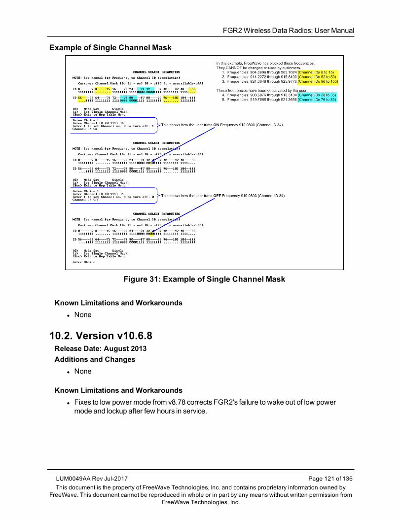
FGR2WirelessData Radios: User Manual
Example of Single Channel Mask
Figure 31: Example of Single Channel Mask
Known Limitations and Workaroundsl None
10.2. Version v10.6.8Release Date: August 2013Additions and Changes
l None
Known Limitations and Workaroundsl Fixes to low power mode from v8.78 corrects FGR2's failure to wake out of low powermode and lockup after few hours in service.
LUM0049AA Rev Jul-2017 Page 121 of 136This document is the property of FreeWave Technologies, Inc. and contains proprietary information owned by
FreeWave. This document cannot be reproduced in whole or in part by any means without written permission fromFreeWave Technologies, Inc.

10. FGR2Release Notes
Page 122 of 136 LUM0049AA Rev Jul-2017This document is the property of FreeWave Technologies, Inc. and contains proprietary information owned by
FreeWave. This document cannot be reproduced in whole or in part by any means without written permission fromFreeWave Technologies, Inc.
10.3. Version v10.6.7Release Date: July 2013
Note: If upgrading from firmware 8.77 or 8.78 to firmware v10.6.7 and experience issues orinconsistent results, contact FreeWave Technical Support at 303.381.9200 or by email [email protected].
Additions and Changesl Corrected problemwith serial radios set to RS485 changing to RS232 operation when nosetting change wasmade.l This change only applies to radios that include an RS485 setting for the serial interface.
Known Limitations and Workaroundsl In theNetwork Diagnostics application in Tool Suite, the radios report having theincorrect firmware version installed.
l On theOperation Mode tab in Tool Suite (Modem Modemenu in the terminal interface),Ethernet parameters appear.l These options do not apply to this radio.
l Supply voltage readings in Tool Suite can fluctuate and differ from those readings on anexternal voltagemeter.
l When theUse Break to Access Setup setting is set to use the radio's current baud rate(a setting only available through the terminal interface), the Diagnostic port's baud ratedoes not set to the default or theBaud Rate setting, resulting in unreadable output. If youuse thisUse Break to Access Setup setting, use the data port for configuration.
10.4. Version v10.6.6Release Date: October 2012Additions and Changes
l Updated firmware version to use the vX.X.X format.l Added AES 128, 192, and 256 encryption capability. AES functionality is enabled at thefactory. To upgrade an existing radio to use the AES functionality, contact FreeWaveTechnical Support.l AES optionsMUST be set using the terminal interface.l Tool Suite versions 2.9.0.0 and earlier do NOT include AES.
l Removed the Ultra Low Power Mode feature.
FGR2WirelessData Radios: User Manual
Known Limitations and Workaroundsl In theNetwork Diagnostics application in Tool Suite, the radios report having theincorrect firmware version installed.
l On theOperation Mode tab in Tool Suite (Modem Modemenu in the terminal interface),Ethernet parameters appear.l These options do not apply to this radio.
10.5. Version 8.78Release Date: December 2011Additions and Changes
l AES zeroization - AES capability now supports zeroization, attempting to hold to NAVSOP5239, and various locks and checks against zeroized keys. (This update does not apply toFGR2models).
l Clear 8th data bit when set to 7 data bits - In a case where one radio is programmedwith 7 data bits, and parity enabled, the parity bit is transferred by the radios as the 8th databit, and sent out the porton the other side. This corrupts the data. Now if the radio is set to 7 data bits, it clears the8th data bit on serial receive.
l Repeater un-shifts timing in OTA slot - Repeaters shift half of their timing to ensuretheir transmissions lineup exactly in time with themasters (2nd layer deep). During an overthe air firmware upgrade, the repeater shifted half of it's timing, but did not unshift thetiming. This could build into a timing problem causing drop of link on sufficient missedpackets.
l Ultra Low Power Mode -ULPM Enable andULPM Sleep parameters now available inthe Transmission Characteristics settings. For more information aboutUltra Low PowerMode, see the Parameter Reference chapter in thismanual.
10.6. Version 8.77Release Date: May 2011Additions and Changes
l Added support for mirror bits andmulti-bandmaster sync.l You can now select Mirrored Bit Master or Mirrored Bit Slave as an operationmode.
10.7. Version 8.73Release Date: October 2009Additions and Changes
l RS485 Protocol fixed.l Use BreakCommand to Enter Setup function fixed.l GrandMaster mode (for Multi-Master Sync) feature fixed.
LUM0049AA Rev Jul-2017 Page 123 of 136This document is the property of FreeWave Technologies, Inc. and contains proprietary information owned by
FreeWave. This document cannot be reproduced in whole or in part by any means without written permission fromFreeWave Technologies, Inc.

10. FGR2Release Notes
Page 124 of 136 LUM0049AA Rev Jul-2017This document is the property of FreeWave Technologies, Inc. and contains proprietary information owned by
FreeWave. This document cannot be reproduced in whole or in part by any means without written permission fromFreeWave Technologies, Inc.
10.8. Version 8.71Release Date: August 2009Additions and Changes
l Improved efficiency and reliability of writing TDMA settings tomemory.l Improved efficiency and reliability of writing Diagnostics settings tomemory.
10.9. Version 8.70Release Date: March 2009Additions and Changes
l Mirror back-end changes.
10.10. Version 8.69Release Date: October 2008Additions and Changes
l Link acquisition issue corrected.
10.11. Version 8.68 (Initial Release)Release Date: June 2008

FGR2WirelessData Radios: User Manual
Appendix A: FGR2 Technical Specifications
Specificationsmay change at any time without notice. For themost up-to-date specificationsinformation, see the product's data sheet available at www.freewave.com.
Note: These are the specifications for all FGR2models.
FGR2 Technical SpecificationsFrequency 902 to 928MHz
TransmitterOutput Power 5mW to 1W
Range 60miles Line Of Sight
Modulation 2 level GFSK
RF Data Rate l Standard-Speed, 115.2 Kbpsl High-Speed, 153.6 Kbps
Occupied bandwidth 230 kHz
Hopping Patterns 15 per Band, 105 total, user selectable
Hopping Channels 50 to 112, user selectable
Hopping Bands 7, user selectable
Frequency Zones 16 zones
ReceiverNominal Sensitivity l -109dBm at Standard-Speed, 1x10-4 bit error rate
l -105dBm at High-Speed, 1x10-4 bit error rate
IF Selectivity 40 dB at fc +/- 230 kHz
LUM0049AA Rev Jul-2017 Page 125 of 136This document is the property of FreeWave Technologies, Inc. and contains proprietary information owned by
FreeWave. This document cannot be reproduced in whole or in part by any means without written permission fromFreeWave Technologies, Inc.

Appendix A: FGR2 Technical Specifications
Page 126 of 136 LUM0049AA Rev Jul-2017This document is the property of FreeWave Technologies, Inc. and contains proprietary information owned by
FreeWave. This document cannot be reproduced in whole or in part by any means without written permission fromFreeWave Technologies, Inc.
FGR2 Technical SpecificationsRF Selectivity 50 db at 869MHz, 935MHz
Dynamic Range +10dBm 3rdOrder Intercept Point at Input Connector
Data TransmissionError Detection 32 Bit CRC, retransmit on error
Data Encryption l AES 128/192/256 Bit Encryption*l Proprietary Spread Spectrum Technology
Data Throughput l 115.2 Kbps, at High-Speed RF Data Ratel 80 Kbps, at Standard-Speed RF Data Rate
Data Interface Serial, 1200 bps to 230.4 Kbps
Protocol RS232 / RS485 / RS422
Note: TTL in the FGR2-T
Power RequirementsOperating Voltage +6.0 to +30.0 VDC**
l FGR2-CE: May be powered through pin 6 of DB9 connector.l FGR2-CE-U: May be powered through pin 6 of DB9 connector.l Waterproof FGR2-WC: 6 foot data and power pigtail provided.l Waterproof FGR2-WC: Data and power cable also available terminatedwith DB9 and power jack.
Typical Current (mA) Mode +6.5 VDC +12 VDC +30 VDCTransmit 700 365 150
Receive 85 48 26
Idle 19 11 8
Sleep 5 3 3
Product SafetyStandards EN 60079-0:2012 + A11:2013 and EN 60079-15:2010
Labeling InformationII 3 G Ex nA IIC Gc
DEMKO 14 ATEX 1209313UGeneral InformationOperating TemperatureRange
-40°C to +75°C-40°F to +167°F
Humidity 0% to 95% non-condensing

FGR2WirelessData Radios: User Manual
FGR2 Technical SpecificationsDimensions l FGR2-C-U: 137 L x 62W x 15 H (mm)
l FGR2-CE-U: 173 L x 107W x 35 H (mm)l FGR2-T-U: 137 L x 62W x 15 H (mm)l FGR2-WC: 165 L x 78W x 60 H (mm)
Weight l FGR2-C-U: 58gl FGR2-CE-U: 504gl FGR2-T-U: 58gl FGR2-WC: 496g
Diagnostics Connector l FGR2-WC: Fischer 11-pinData Connector l FGR2-C-U:
l 10-pin shrouded header with locking rampl 0.1 inch spacingl power / data connector
l FGR2-CE-U: DB9l FGR2-T-U:
l 10-pin shrouded header with locking rampl 0.1 inch spacingl power / data connector
l FGR2-WC: Fischer 11-pinRF Connector l FGR2-C-U: SMA female connector
l FGR2-CE-U: TNC-Enclosed version only (Female connector)l FGR2-T-U: SMA female connectorl FGR2-WC: N type female connector
Enclosure l FGR2-C-U: None. Board-levell FGR2-CE-U: Extruded aluminuml FGR2-T-U: None. Board-levell FGR2-WC: Extruded aluminum, waterproof
* Contact a FreeWave reseller or sales representative for implementation details.
FREEWAVE Recommends: ** UL approved FGR2 radios are approved for use between +6.0 to+30.0 VDC.However, for optimal performance, FreeWave recommends using a power supply between +7.5VDCand +30VDC.
LUM0049AA Rev Jul-2017 Page 127 of 136This document is the property of FreeWave Technologies, Inc. and contains proprietary information owned by
FreeWave. This document cannot be reproduced in whole or in part by any means without written permission fromFreeWave Technologies, Inc.

Page 128 of 136 LUM0049AA Rev Jul-2017This document is the property of FreeWave Technologies, Inc. and contains proprietary information owned by
FreeWave. This document cannot be reproduced in whole or in part by any means without written permission fromFreeWave Technologies, Inc.
Appendix B: FGR2 Board Level Mechanical Drawing

FGR2WirelessData Radios: User Manual
Appendix C: 900MHz Factory Default Settings
900MHz Factory Default SettingsOperation Mode Default MultiPoint Parameters DefaultPoint-to-Point Slave 1 (0) Number of Repeaters 1
Set Baud Rate Default (1) Master Packet Repeat 2
Baud Rate 115200 (2) Max Slave Retry 9
(A) Data Parity 0 (3) Retry Odds 9
(B) Modbus RTU 0 (4) DTR Connect 0
(C) RS232/485 0 (5) Repeatr Frequency 0
(D) Setup Port 3 (6) Network ID 255
(E) Turn Off Delay / On Delay 0/0 (7) Reserved -
(F) Flow Control 0 (8) MultiMaster Sync 0
Radio Parameters Default (9) 1 PPS Enable Delay 255
(0) Freq Key 5 (A) Slave/Repeater 0
(0) Hop Table Version 0 (B) Diagnostics 0
(1) Hop Table Size 112 (C) Subnext ID “Disabled”
(2) Hop FreqOffset 0 Rx ID F
(3) Frequency Zone All 1s (Enabled) Tx ID F
(4) Government Rules 0 (D) Radio ID Not Set
(1) Max Packet Size 8 (E) Local Access 0
(2) Min Packet Size 9 (G) Radio Name "blank"
LUM0049AA Rev Jul-2017 Page 129 of 136This document is the property of FreeWave Technologies, Inc. and contains proprietary information owned by
FreeWave. This document cannot be reproduced in whole or in part by any means without written permission fromFreeWave Technologies, Inc.

Appendix C: 900MHzFactory Default Settings
Page 130 of 136 LUM0049AA Rev Jul-2017This document is the property of FreeWave Technologies, Inc. and contains proprietary information owned by
FreeWave. This document cannot be reproduced in whole or in part by any means without written permission fromFreeWave Technologies, Inc.
900MHz Factory Default SettingsOperation Mode Default MultiPoint Parameters Default(3) Xmit rate 1
(4) RF Data Rate 3
(5) RF Xmit Power 10
(6) Slave Security 0
(7) RTS to CTS 0
(8) Retry Timeout 255
(9) Low PowerMode 0
(A) High Noise 0
(B) MCU Speed 0
(C) Remote LED 0
(E) Encryption
Strength (0) Off
Enter Key Blank
Channel Key Blank

FGR2WirelessData Radios: User Manual
Appendix D: 900MHz Channel Frequency IDs
Note: See 900MHz Channel Select Parameters (on page 41) for additional information.
900MHz Channel Frequency IDsID Frequency ID Frequency ID Frequency0 902.2464 40 911.4624 80 920.6784
1 902.4768 41 911.6928 81 920.9088
2 902.7072 42 911.9232 82 921.1392
3 902.9376 43 912.1536 83 921.3696
4 903.1680 44 912.3840 84 921.6000
5 903.3984 45 912.6144 85 921.8304
6 903.6288 46 912.8448 86 922.0608
7 903.8592 47 913.0752 87 922.2912
8 904.0896 48 913.3056 88 922.5216
9 904.3200 49 913.5360 89 922.7520
10 904.5504 50 913.7664 90 922.9824
11 904.7808 51 913.9968 91 923.2128
12 905.0112 52 914.2272 92 923.4432
13 905.2416 53 914.4576 93 923.6736
14 905.4720 54 914.6880 94 923.9040
15 905.7024 55 914.9184 95 924.1344
LUM0049AA Rev Jul-2017 Page 131 of 136This document is the property of FreeWave Technologies, Inc. and contains proprietary information owned by
FreeWave. This document cannot be reproduced in whole or in part by any means without written permission fromFreeWave Technologies, Inc.

Appendix D: 900MHzChannel Frequency IDs
Page 132 of 136 LUM0049AA Rev Jul-2017This document is the property of FreeWave Technologies, Inc. and contains proprietary information owned by
FreeWave. This document cannot be reproduced in whole or in part by any means without written permission fromFreeWave Technologies, Inc.
900MHz Channel Frequency IDsID Frequency ID Frequency ID Frequency16 905.9328 56 915.1488 96 924.3648
17 906.1632 57 915.3792 97 924.5952
18 906.3936 58 915.6096 98 924.8256
19 906.6240 59 915.8400 99 925.0560
20 906.8544 60 916.0704 100 925.2864
21 907.0848 61 916.3008 101 925.5168
22 907.3152 62 916.5312 102 925.7472
23 907.5456 63 916.7616 103 925.9776
24 907.7760 64 916.9920 104 926.2080
25 908.0064 65 917.2224 105 926.4384
26 908.2368 66 917.4528 106 926.6688
27 908.4672 67 917.6832 107 926.8992
28 908.6976 68 917.9136 108 927.1296
29 908.9280 69 918.1440 109 927.3600
30 909.1584 70 918.3744 110 927.5904
31 909.3888 71 918.6048 111 927.8208
32 909.6192 72 918.8352
33 909.8496 73 919.0656
34 910.0800 74 919.2960
35 910.3104 75 919.5264
36 910.5408 76 919.7568
37 910.7712 77 919.9872
38 911.0016 78 920.2176
39 911.2320 79 920.4480

FGR2WirelessData Radios: User Manual
Appendix E: FreeWave Legal Information
Restricted RightsAny product names mentioned in this manual may be trademarks or registered trademarks of their respectivecompanies and are hereby acknowledged.This manual is for use by purchasers and other authorized users of FreeWave products.No part of this manual may be reproduced or transmitted in any form or by any means, electronic or mechanical,or for any purpose without the express written permission of FreeWave Technologies, Inc. FreeWave reservesthe right to make changes to this manual without notice. FreeWave assumes no responsibility or liability for theuse of this manual or the infringement of any copyright or other proprietary right. FreeWave products are designed and manufactured in the United States of America.
Export NotificationFreeWave Technologies, Inc. products may be subject to control by the Export Administration Regulations(EAR) and/or the International Traffic in Arms Regulations (ITAR). Export, re-export, or transfer of theseproducts without required authorization from the U.S. Department of Commerce, Bureau of Industry andSecurity, or the U.S. Department of State, Directorate of Defense Trade Controls, as applicable, isprohibited. Any party exporting, re-exporting, or transferring FreeWave products is responsible forobtaining all necessary U.S. government authorizations required to ensure compliance with these and otherapplicable U.S. laws. Consult with your legal counsel for further guidance.
UL Notifications / Warnings - Class1 Div2
Warning! EXPLOSION HAZARD! - Substitution of components may impair suitability for Class 1,Division 2.
Warning! DO NOT REMOVE or insert the diagnostics cable while the circuit is live!
LUM0049AA Rev Jul-2017 Page 133 of 136This document is the property of FreeWave Technologies, Inc. and contains proprietary information owned by
FreeWave. This document cannot be reproduced in whole or in part by any means without written permission fromFreeWave Technologies, Inc.
Appendix E: FreeWave Legal Information
Page 134 of 136 LUM0049AA Rev Jul-2017This document is the property of FreeWave Technologies, Inc. and contains proprietary information owned by
FreeWave. This document cannot be reproduced in whole or in part by any means without written permission fromFreeWave Technologies, Inc.
UL Power SourceInput voltage for the listed models is +6.0 to +30.0 VDC.
Important!: Input power shall be derived from a single Class 2 power source.
Do not connect or disconnect any connectors while the circuit is live unless the area is known to be non-hazardous.
Warning! The FGR2-WC model described in this User Manual is NOT UL certified.
l Models FGR2-C-U, FGR2-CE-U, and FGR2-T-U are suitable for use in Class 1, Division 2, Groups A, B,C, and D or non-hazardous locations only.
IC NotificationsThis device complies with Industry Canada license-exempt RSS standard(s). Operation is subject to thefollowing two conditions: (1) this device may not cause interference, and (2) this device must accept anyinterference, including interference that may cause undesired operation of the device.Ce dispositif est conforme aux normes permis-exemptes du Canada RSS d'industrie. L'opération est sujette auxdeux conditions suivantes : (1) ce dispositif peut ne pas causer l'interférence, et (2) ce dispositif doit acceptern'importe quelle interférence, y compris l'interférence qui peut causer le fonctionnement peu désiré du dispositif.
FCC NotificationsThis device complies with part 15 of the FCC rules. Operation is subject to the following two conditions: 1) Thisdevice may not cause harmful interference and 2) this device must accept any interference received, includinginterference that may cause undesired operation.The content of this guide covers FreeWave Technologies, Inc. models sold under FCC ID: KNY-42182112519.All models sold under the FCC ID(s) listed above must be installed professionally and are only approved for usewhen installed in devices produced by FreeWave Technologies or third party OEMs with the express writtenapproval of FreeWave Technologies, Inc. Changes or modifications should not be made to the device.The antennas used MUST have a separation distance of at least 23 cm from all persons and MUST NOT be co-located or operate in conjunction with any other antenna or transmitter.
FCC NEMA Installation and LabelWhere applicable, the models described in this guide must be installed in a NEMA enclosure. When anyFreeWave Technologies, Inc. module is placed inside an enclosure, a label must be placed on the outside of theenclosure. The label must include the text "Contains Transmitter Module with FCC ID: KNY-42182112519."
FCC Notification of Power WarningThe FGR2 Wireless Data Radios covered in this document have a maximum transmitted output power of 1000mW.The antennas used MUST have a separation distance of at least 23 cm from all persons and MUST NOT be co-located or operate in conjunction with any other antenna or transmitter.
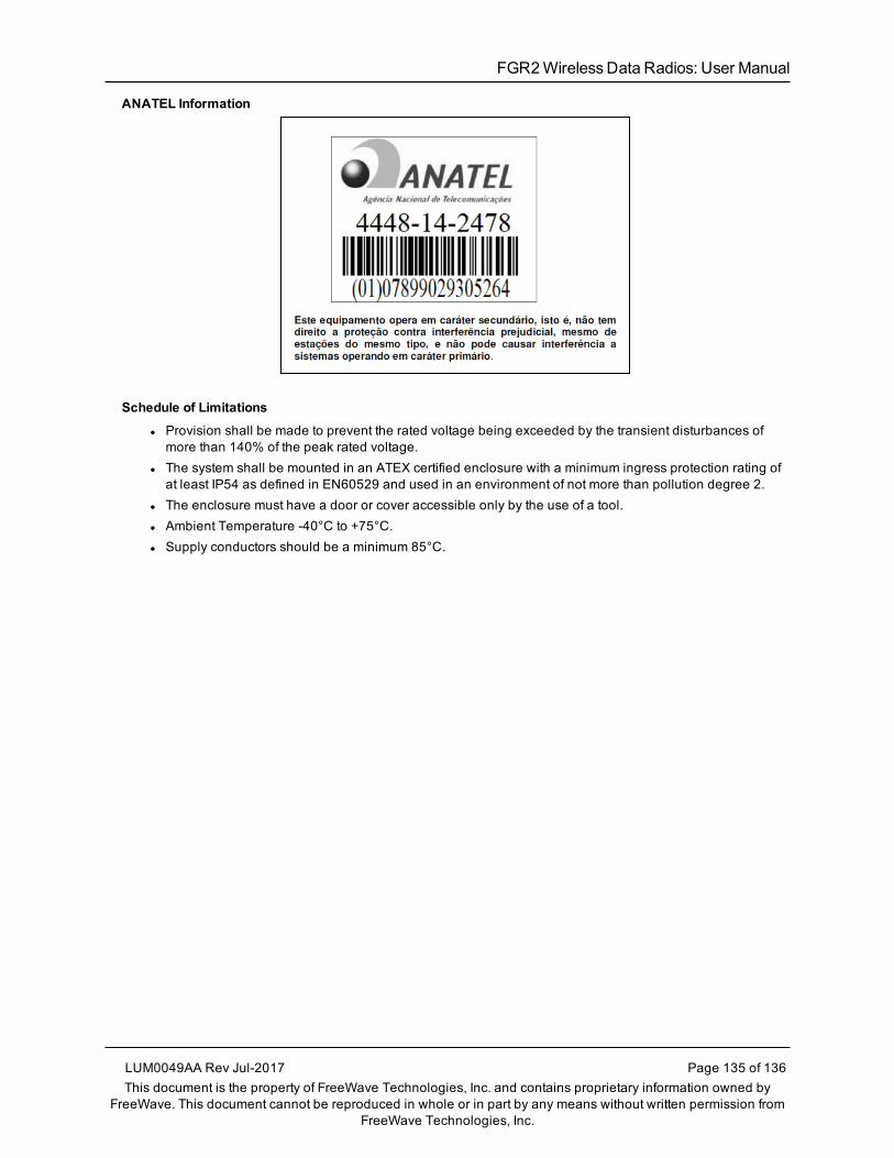
FGR2WirelessData Radios: User Manual
ANATEL Information
Schedule of Limitations
l Provision shall be made to prevent the rated voltage being exceeded by the transient disturbances ofmore than 140% of the peak rated voltage.
l The system shall be mounted in an ATEX certified enclosure with a minimum ingress protection rating ofat least IP54 as defined in EN60529 and used in an environment of not more than pollution degree 2.
l The enclosure must have a door or cover accessible only by the use of a tool.l Ambient Temperature -40°C to +75°C.l Supply conductors should be a minimum 85°C.
LUM0049AA Rev Jul-2017 Page 135 of 136This document is the property of FreeWave Technologies, Inc. and contains proprietary information owned by
FreeWave. This document cannot be reproduced in whole or in part by any means without written permission fromFreeWave Technologies, Inc.