Embed Size (px)
Citation preview

Research Misconceptions and Rectifications
FERROELECTRIC DEVICES &
PIEZOELECTRIC ACTUATORS
Kenji Uchino, MS, MBA, Ph.D.Electrical Engineering, Materials Science and Engineering,
and International Center for Actuators and Transducers,The Pennsylvania State University

srotautcA cirtceleozeiP & seciveD cirtceleorreF
hcetSED .cnI ,snoit ac il buP teertS ekuD htroN 934
.A.S.U 20671 ain av lys nneP ,ret sac naL
thgir ypoC © yb 7102 hcetSED .cnI ,snoit ac il buP devres er sthgir llA
a ni derots ,decud orp er eb yam noit ac il bup siht fo trap oN ,snaem yna yb ro mrof yna ni ,det tim snart ro ,met sys laveirt er
,esiw re hto ro ,gni droc er ,gni ypoc ot ohp ,lac i nahc em ,cinort cele.rehsil bup eht fo nois sim rep net tirw roirp eht tuo htiw
aci remA fo setatS detinU eht ni detnirP1 2 3 4 5 6 7 8 9 01
:elt it red nu yrt ne niaMsnoitacifitceR dna snoitpecnocsiM hcraeseR :srotautcA cirtceleozeiP & seciveD cirtceleorreF
A hcetSED koob snoit ac il buP .p :yhp ar go il biB
332 .p xed ni sedulc nI
9192496102 :rebmuN lortnoC ssergnoC fo yrarbiL0-213-59506-1-879 :NBSI

ix
Preface
ACTUATOR applications of piezoelectrics started in the late 1970s, which were followed in the next decade by major investments
aimed at practical implementation, such as precision positioners with high-strain materials, multilayer device design, mass fabrication pro-cesses for portable electronic devices, ultrasonic motors for microrobot-ics, and smart structures. After the slump due to the worldwide reces-sion, we are now experiencing a kind of “renaissance” of piezoelectric actuators, which are being put to use in sustainable environmental ap-plications like energy-saving systems, as well as in emerging “active” biomedical devices.
To stimulate and challenge researchers in this area, I created a teach-ing tool originally titled the “Researchers’ Misconceptions Top 10” list. This list of ideas and approaches was intended to encourage interdis-ciplinary thought and discussion among the materials, electrical and mechanical engineers working on piezoelectrics and actuators. I had discovered that certain misconceptions were creeping into teaching and instruction on these topics. Over time, as both an academic authority and an industry executive, I collected and codified these misconcep-tions, of which a number are spelled out in the box below—along with their sources. From reflection on these and similar ideas, the current book has grown.
As a starting point, the reader is invited to consider the following ten statements and indicate which are true and which are false. (In fact, all are false, and the reasons why are spelled out in the pages that follow.)

Prefacex
1. Electrostriction is caused by a slight displacement of ions in the crystal lattice under field. This displacement will accumulate throughout the bulk and result in an overall strain along the field (cited from a famous encyclopedia).
2. When 1 J electric energy is input to a piezoelectric with an elec-tromechanical coupling factor k, we can expect k 2 J mechanical energy converted in this piezo-material. Thus, we can conclude that the efficiency of this device is k 2 % (cited from a journal paper on mechanical engineering).
3. By applying 1 J electric energy on a piezoelectric with an elec-tromechanical coupling factor k, we accumulated k 2 J mechani-cal energy in this piezo-material. Thus, this actuator can work mechanically up to k 2 J to the outside (cited from a journal paper on mechanical engineering).
4. Elastic compliances and sound velocity are the material’s con-stants in a piezoelectric. Thus, the resonance frequencies are merely determined by the sample size.
5. PZT with the high electromechanical coupling factor k is the best piezoelectric material for heart beat monitoring sensors (from a conversation with an electrical engineering professor).
6. When a piezo-actuator generates unwelcome vibration ringing in a mechanical system, the best solution is to install a suitable mechanical damper in the system (from a conversation with a mechanical engineer).
7. The resonance mode is only the mechanical resonance, while the anti-resonance mode is not a mechanical resonance (from a conversation with a materials professor).
8. The resonance mode is the most efficient driving condition of the piezoelectric transducer.
9. Improving performance is the best way to discover a “best-sell-ing” (i.e., commercially successful) device (most of the profes-sors).
10. The device developer should focus solely on “component” de-velopment and purchase the driving circuit from outside, in order to reduce development costs and time (most industrial engineers).

xiPreface
These misconceptions are traceable to faulty ideas regarding the definitions of ionic displacement and strain, efficiency, the energy transmission coefficient, the constraint-dependency of piezo-materials’ properties, impedance matching, piezoelectric dampers, resonance and anti-resonance, and system design principles. Part I of this text explains, and gives solutions for, the misconceptions.
Part II is devoted to the problem solving of “ferroelectric devices,” which extends the book’s coverage beyond piezoelectric actuators. The reason is this. In 2010 I authored Ferroelectric Devices, a textbook now used in classrooms worldwide and containing over one hundred edu-cational problems. In the interim, I received a flood of requests from course instructors (and their students) for detailed answers to all the chapter problems, so they could teach (and take) the course with con-fidence. Thus, the latter part of the present volume presents clear and detailed solutions to problems in ferroelectrics.
It is assumed the reader has learned about ferroelectrics, either from the above-mentioned Ferroelectric Devices or an equivalent funda-mental textbook. The present, more advanced volume, can be used to supplement the reader’s knowledge by rectifying misconceptions and providing practice in ferroelectric problem solving.
KENJI UCHINO MS, MBA, Ph.D.Penn State University January, 2016

1
PART 1
Researchers’ Misconceptions
BACKGROUND
ACTUATOR applications of piezoelectrics started in the late 1970s, and enormous investment was installed on practical developments
during the 1980s aiming at consumer applications such as precision positioners with high strain materials, multilayer device designing, and mass-fabrication processes for portable electronic devices, ultrasonic motors for micro-robotics, and smart structures. After the slump due to the worldwide economic recession in the late 1990s, there is a sort of “renaissance” of piezoelectric actuators according to the social environ-mental changes for sustainability (i.e., energy saving, biomedical areas) and crisis technologies. Figure 1 shows the piezoelectric device mar-ket estimated from multiple sources [1]. The 2014 revenue around $25 billion will expand to $40 billion by 2017. Actuator/piezo-generator (energy harvesting) is the largest category, followed by transducer/sen-sor/accelerometer/piezo-transformer. Then, resonator/acoustic device/ultrasonic motor category chases.
The “piezoelectric actuator” is really an interdisciplinary area to which materials and applied physics, electrical and mechanical engi-neers are primarily approaching. Because of narrow knowledge of ju-nior professors, they occasionally instruct the students with a sort of misconception, reflecting the delay of innovative developments in the next generation. The top 10 among these misconceptions, which are primarily related with the misconceptions on the understanding of ionic displacement and strain, efficiency, energy transmission coefficient,

RESEARCHERS’ MISCONCEPTIONS2
constraint-dependency of piezo-materials’ properties, mechanical im-pedance matching, piezoelectric damping mechanism, resonance and antiresonance, best-selling devices, and system design principle are re-viewed. Table 1 summarizes the top 10 among these (all statements are actually false). If you do not find any “false” content in each question, you are a serious patient, and you should read this tutorial article further as a prescription for your successful future development. The author’s philosophy: “Without a strong fundamental understanding, no break-through invention comes out.”
STRAIN VERSUS IONIC DISPLACEMENT (Question 1)
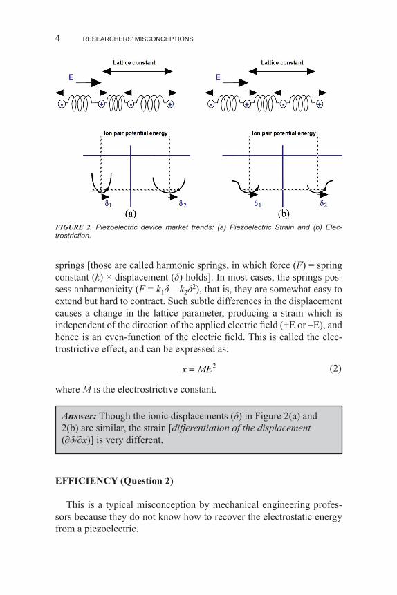
The reason why a strain is induced by an electric field is explained in Question 1. For simplicity, let us consider an ionic crystal such as NaCl [2]. Figure 2 shows a one-dimensional rigid-ion spring model of the crystal lattice (Uchino’s model, introduced in his thesis 1978). The springs represent equivalently the cohesive force resulting from the electrostatic Coulomb energy and the quantum mechanical repulsive energy. Figure 2(b) shows a centrosymmetric case (like NaCl), whereas Figure 2(a) shows a more general noncentrosymmetric case. In Figure 2(b), the springs joining the ions are all the same, whereas in Figure 2(a), the springs joining the ions are different for the longer and shorter ionic distances. In other words, hard and soft springs existing alter-nately are important. Next, consider the state of the crystal lattice in Figure 2(a) under an applied electric field. The cations are drawn in the direction of the electric field and the anions in the opposite direction, leading to the relative change in the interionic distance. Depending on
FIGURE 1. Piezoelectric device market trends.

3
the direction of the electric field, the soft spring expands or contracts more than the contraction or expansion of the hard spring, causing a strain x (a unit cell length change) in proportion to the electric field E. This is the converse piezoelectric effect. When expressed as:
x dE=
the proportionality constant d is called the piezoelectric constant. On the other hand, in Figure 2(b), the amounts of extension and con-
traction of the spring are nearly the same [though ionic displacements are similar to Figure 2(a)], and the distance between the two cations (lattice parameter) remains almost the same, hence, there is no strain. However, more precisely, ions are not connected by such idealized
Strain versus Ionic Displacement (Question 1)
(1)
TABLE 1. Professors’ Top 10 Piezoelectric Actuators Misconceptions.
1 . Electrostriction is caused by a slight displacement of ions in the crystal lattice under field. This displacement will accumulate throughout the bulk and result in an overall strain along the field (cited from a famous encyclopedia).
2 . When 1 J electric energy is input to a piezoelectric with an electromechanical coupling factor k, we can expect k2 J mechanical energy converted in this piezo-material. Thus, we can conclude that the efficiency of this device is k2% (cited from a journal paper on mechanical engineering).
3 . By applying 1 J electric energy on a piezoelectric with an electromechanical coupling factor k, we accumulated k2 J mechanical energy in this piezo-material . Thus, this actuator can work mechanically up to k2 J to the outside (cited from a journal paper on mechanical engineering).
4 . Elastic compliances and sound velocity are the material’s constants in a piezo-electric . Thus, the resonance frequencies are merely determined by the sample size .
5 . PZT with the high electromechanical coupling factor k is the best piezoelectric material for heart beat monitoring sensors (from a conversation with an electrical engineering professor).
6 . When the piezo-actuator generates unwelcomed vibration ringing in the mechani-cal system, the best way is to install a suitable mechanical damper in the system (from a conversation with a mechanical engineer).
7 . The resonance mode is only the mechanical resonance, while the antiresonance mode is not a mechanical resonance (from a conversation with a materials pro-fessor).
8 . The resonance mode is the best efficient driving condition of the piezoelectric transducer .
9 . Improving the performance is the best way for seeking for the successful “best-selling” device (most of the professors).
10 . The device developer should focus merely on the “component” development by purchasing the driving circuit from the outside for reducing the development cost and period (most of industrial engineers).
RESEARCHERS’ MISCONCEPTIONS4
springs [those are called harmonic springs, in which force (F) = spring constant (k) × displacement (δ) holds]. In most cases, the springs pos-sess anharmonicity (F = k1δ – k2δ2), that is, they are somewhat easy to extend but hard to contract. Such subtle differences in the displacement causes a change in the lattice parameter, producing a strain which is independent of the direction of the applied electric field (+E or –E), and hence is an even-function of the electric field. This is called the elec-trostrictive effect, and can be expressed as:
x ME= 2
where M is the electrostrictive constant.
FIGURE 2. Piezoelectric device market trends: (a) Piezoelectric Strain and (b) Elec-trostriction.
(2)
Answer: Though the ionic displacements (δ) in Figure 2(a) and 2(b) are similar, the strain [differentiation of the displacement (∂δ/∂x)] is very different.
EFFICIENCY (Question 2)
This is a typical misconception by mechanical engineering profes-sors because they do not know how to recover the electrostatic energy from a piezoelectric.

5
First of all, remember the following constitutive equations:
D E dXX= +ε
x dE s XE= +
where d is the piezoelectric constant, sE is the elastic compliance un-der short-circuit condition, and εX is the permittivity under stress-free condition. Then, the electromechanical coupling factor k is defined by:
k d sE X2 2= ε
The value k2 has a meaning of energy conversion rate, that is,
k2 = (stored mechanical energy)/(input electrical energy)
Taking an example value k = 70% for a piezoelectric pseudo DC device, k2 = 50%, then the input electrical energy 100 is converted into mechanical energy 50, by remaining 49 as stored electrical energy (in a capacitor). Because the loss factor (dielectric loss tan δ) is less than 1%, actual loss dissipated as heat is usually less than 1% (refer to Resonance and Antiresonance Modes: Efficiency). The energy conversion process is visualized in Figure 3(a). Thus, if we can collect the stored electrical energy back to the drive circuit, we can declare that the loss is only 1%. On the contrary, the efficiency η is defined by:
η = (output mechanical energy)/(consumed electrical energy)
If we can recover the mechanically unconsumed energy (stored in the piezoelectric elastic material, i.e., spring), we can consider that the actual consumed electric energy should be the sum of output mechani-cal energy (work to the outside) and heat loss, leading to 99% (very high).
Because the mechanical engineering professor did not know how to recover the electrostatic energy stored in the actuator/capacitor, he released it by shorting the drive circuit in order to move to the next op-eration. Of course, in this worst scenario, the efficiency less than 50% (equal to k2) is true in his paper.
Now, how can we recover the electrostatic energy from the piezo-electric? Let us consider dot-matrix/ink-jet printer and diesel injection valve control applications, where multilayer actuators are driven at < 1 kHz, much lower than the resonance frequency. Refer to an equiva-lent circuit (k31 mode) shown in Figure 3(b). In this equivalent circuit,
Efficiency (Question 2)
(3)
(4)
(5)
(6)
(7)

RESEARCHERS’ MISCONCEPTIONS6
motional current and damped current [Cd = (1 – k2)C0] should havek2 : (1 – k2) ratio under an off-resonance condition. If we insert the in-ductance L in the driving system so as to create a resonance circuit of L and Cd under the condition of ω2 = 1/LCd (ω: operation cycle such as 1 kHz), the electric energy stored in the damped capacitance Cd starts flip-flopping with L, without losing this energy. A negative capacitance usage is an alternative solution recently.
FIGURE 3. (a) Energy conversion rate in a typical piezoelectric. (b) Equivalent circuit (k31 mode).
Answer: The efficiency of the piezoelectric devices is high around 99%, if we recover the stored electric energy with a suitably selected inductance or a negative capacitance.
ENERGY TRANSMISSION COEFFICIENT (Question 3)
Not all the mechanically stored energy can actually be used, and the actual work done depends on the mechanical load [Figure 3(a)]. With zero mechanical load or complete clamp condition (i.e., no strain), no

7
output work is done or no energy is spent to the outside. The energy transmission coefficient is defined by:
λmax = (output mechanical energy/input electrical energy)max
or equivalently,
λmax = (output electrical energy/input mechanical energy)max
The difference of the above from Equations (6) and (8) is “stored” or “output/spent.”
Let us consider the simplest case where an electric field E is applied to a piezoelectric under constant external stress X (< 0, compressive stress). This corresponds to the situation that a mass is put suddenly on the actuator, as shown in Figure 4(a) [2]. Figure 4(b) shows two electric-field versus induced-strain curves, corresponding to two condi-
Energy Transmission Coefficient (Question 3)
(8)
FIGURE 4. Calculation of the input electrical and output mechanical energy: (a) load mass model for the calculation; (b) electric field versus induced strain curve; (c) stress versus strain curve; and (d) electric field versus polarization curve.

RESEARCHERS’ MISCONCEPTIONS8
tions; under the mass load and no mass. Because the area on the field-strain domain does not mean the energy, we should use the stress-strain and field-polarization domains in order to discuss the mechanical and electrical energy, respectively. Figure 4(c) illustrates how to calculate the mechanical energy. Note that the mass shrinks the actuator first by sX (s: piezo-material’s compliance, and X < 0). This mechanical energy sX 2 is a sort of “loan” of the actuator credited from the mass, which should be subtracted later. This energy corresponds to the hatched area in Figure 4(c). By applying the step electric field, the actuator expands by the strain level dE under a constant stress condition. This is the me-chanical energy provided from the actuator to the mass, which corre-sponds to |dEX|. Like paying back the initial “loan,” the output work (from the actuator to the mass) can be calculated as the area subtraction [shown by the dotted area in Figure 4(c)]:
( ) (X dx dE sX X)
Figure 4(d) illustrates how to calculate the electrical energy. The mass load X generates the “loan” electrical energy by inducing P = dX [see the hatched area in Figure 4(d)]. By applying a sudden electric field E, the actuator (like a capacitor) receives the electrical energy of ε0εE 2. Thus, the total energy is given by the area subtraction [shown by the dotted area in Figure 4(d)]:
∫(E)dP = (ε0εE + dX)E
Now, we need to choose a proper load to maximize the energy trans-mission coefficient. From the maximum condition of:
λ ε ε = ( ) ( )dE sX X E dX E+ +0
we can obtain:
λmax [( ) ( ) ] [( ) ( ) ]= − − = + − −1 1 1 1 1 12 2 2 2k k k k
We can verify from Equation (11) that:
k2/4 < λmax < k2/2
depending on the k value. For a small k, λmax = k2/4, and for a large k, λmax = k2/2. It is also worth noting that the maximum condition stated above does not agree precisely with the condition which provides the
(9)
(10)
(11)
9
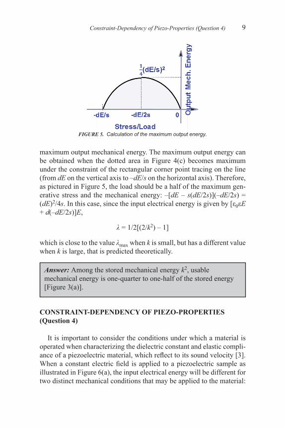
maximum output mechanical energy. The maximum output energy can be obtained when the dotted area in Figure 4(c) becomes maximum under the constraint of the rectangular corner point tracing on the line (from dE on the vertical axis to –dE/s on the horizontal axis). Therefore, as pictured in Figure 5, the load should be a half of the maximum gen-erative stress and the mechanical energy: –[dE – s(dE/2s)](–dE/2s) = (dE)2/4s. In this case, since the input electrical energy is given by [ε0εE + d(–dE/2s)]E,
λ = 1/2[(2/k2) – 1]
which is close to the value λmax when k is small, but has a different value when k is large, that is predicted theoretically.
Constraint-Dependency of Piezo-Properties (Question 4)
FIGURE 5. Calculation of the maximum output energy.
CONSTRAINT-DEPENDENCY OF PIEZO-PROPERTIES (Question 4)
It is important to consider the conditions under which a material is operated when characterizing the dielectric constant and elastic compli-ance of a piezoelectric material, which reflect to its sound velocity [3]. When a constant electric field is applied to a piezoelectric sample as illustrated in Figure 6(a), the input electrical energy will be different for two distinct mechanical conditions that may be applied to the material:
Answer: Among the stored mechanical energy k2, usable mechanical energy is one-quarter to one-half of the stored energy [Figure 3(a)].

RESEARCHERS’ MISCONCEPTIONS10
(1) the mechanically clamped state, where a constant strain is main-tained and the specimen cannot deform (pure electrostatic energy), and (2) the mechanically free state, in which the material is not constrained and is free to deform. We expect then that the total input electrical en-ergy under the free condition will be the sum of the energies associated with pure electrostatic energy (without deformation) and the pure me-chanical energy under a short-circuit condition. This can be expressed by:
12
12
12
2 22
2K E K E dsEX
o oxo o E oε ε
FIGURE 6. Schematic representation of the response of a piezoelectric material under (a) constant applied electric field and (b) constant applied stress conditions.
(12a)

233
Index
acceptor ion, 93acoustic impedance matching, 12, 14,
207, 223adiabatic condition, 143, 144antiresonance, x, xi, 2, 3, 5, 20–25,
27–32, 33, 60, 148, 166–170, 172–174
antiresonance frequency, 22, 23, 25, 27, 31, 33, 166, 172
barium titanate (BaTiO3), 49, 87, 88, 139, 197, 198, 200, 201, 202, 205, 209
Bestseller devices, 226burst method, 24
cantilever, 94, 95, 99–102, 218 ceramic heaters, 197Cole-Cole plot, 110, 115–118combination effect, 207, 208constant current drive, 23constant vibration velocity mode, 26constant voltage, 23, 26, 169constant voltage drive, 23, 169converse piezoelectric effect, 3cost, x, 3, 33, 36, 37, 58, 62–64, 66, 119,
125, 168, 175, 185, 226–230crisis technologies, ix, 1, 226Curie-Weiss Law, 87, 90, 109, 114, 116,
198, 200, 205
damped capacitance, 6, 23, 148, 169–171damping constant, 168, 170damping principle, 208, 209degradation, 119depletion layer, 121–124dielectric relaxation, 109, 111, 134dielectrics, 45, 109, 225dipole coupling, 45, 111donor ion, 93, 106DRAM, 57, 119, 120, 122, 125, 126,
134, durability, 33, 35, 36, 149
efficiency, x, 1, 3, 4, 5, 6, 15, 25, 27, 33, 35, 40, 62, 147, 148, 149, 175, 183, 228, 229,
elastic anharmonic, 45electrical impedance matching, 39, 149,
208, 224electromechanical coupling, x, 3, 5, 11,
12, 22, 25, 28, 29, 39, 49, 50, 94, 95, 129, 147–150, 152, 153, 156, 158, 165, 166, 168, 208, 209, 224
electro-mechanical coupling loss, 228electro-optic light valve, 185electrostriction, ix, 3, 4, 45, 69electrostrictive effect, 4, 193energy conversion rate, 5, 6, 39

Index234
energy transmission coefficient, x, 1, 6, 7, 8, 147, 150–152
external environment analysis, 226extraordinary light, 52, 186
fatigue, 119, 134Fermi level, 120, 122ferroelectrics, 45, 56, 69, 70, 109, 110,
118, 119, 142, 185, 225field effect transistor, 119first-order phase transition, 82, 83, 85,
139, 140forward-biased, 121
GBL capacitors, 197, 198grain boundary layer (GBL) capacitors,
198
half wave voltage, 46, 54, 186–189, 195, 196
in-print, 119inversion current type, 119inversion layer, 120–123
Kerr effect, 46, 55, 185, 194Kerr electro-optic coefficients, 186Kerr electro-optic device, 186Kerr electro-optic effect, 191KTN, 185, 186
Laplace transform, 15, 16, 20, 159, 161light waveguide, 185, 196LiNbO3, 185longitudinally clamped sample, 22
Madelung constant, 48Madelung energy, 47magnetoelectric composites, 208magnetoelectric sensor, 209marketing creativity, 226mechanical impedance mismatch, 38,
39, 175mechanical quality factor, 25, 29, 30, 31,
33, 40, 147, 168mechanical/acoustic impedance, 12–14mechanically clamped state, 10
mechanically free state, 10metal-tube type, 34, 37, 229Michael Porter’s Five Force, 226MOSFET, 119, 120, 122, 123, 134motional capacitance, 22, 23
negative resistance, 198, 201, 202nodal lines, 175
open-circuit state, 11ordinary light , 52
pecking order, 35, 37phase retardation, 51, 187piezoelectric actuator, ix, xi, 1, 3, 14, 35,
36, 56, 98, 149, 150, 209, 210piezoelectric constant, 3, 5, 49, 70, 86,
87, 89, 90, 96, 99–102, 129, 168, 171, 212
piezoelectric strain constant, 147piezoelectric voltage constant, 147, 223piezoelectrics, ix, 1, 25, 27, 30, 40, 45,
67PLZT, 51, 53, 64, 141–143, 185–190,
195, 196Pockels electro-optic coefficient, 46,
186polarizer, 46, 51–54, 66, 186, 187, 191,
195product effect, 207, 208, 226product planning creativity, 226PTC effect, 197PTC thermistor, 45, 202, 226, 230pulse drive technique, 15, 165, 166pyroelectric coefficient, 67, 135–138,
142–144, 215pyroelectrics, 45PZT, x, 3, 12–14, 23, 24, 27–37, 46,
49, 51, 56, 57, 64, 65, 70, 71, 89, 93, 95, 99–101, 104–106, 120, 126–133, 145, 153–155, 158, 174, 175, 180, 185, 207–209, 214 –219, 222–224, 227, 228, 231
PZT tube type, 33, 35
refractive index, 46, 51, 52, 55, 66, 185, 186, 188, 189, 191, 193, 195, 196

235Index
resonance frequency, 5, 22–25, 27, 31, 33, 66, 94, 95, 100, 106, 107, 166, 167, 171, 172, 174, 180
resonance period, 18–20, 100, 150, 161, 163, 165, 168, 183
retardation, 51, 53, 187, 190, 191, 194reverse-biased, 121rhombohedral crystal, 87ringing, x, 3, 14, 15, 17–20, 149,
161–163, 183
scoring table, 36, 37, 228, 229shear strain, 69, 82short-circuit state, 11social/cultural, technological, economic,
and political/legal forces (STEP), 226
strain-free neutral plane, 100, 102sum effect, 207, 208, 223sustainability technologies, 226
technological creativity, 226, 230tensor, 69, 71, 72, 75, 76, 81, 91,
191terfenol, 208, 219, 222, 224tetragonal crystal, 88thermistors, 45, 197, 225transformation matrices, 76transient response, 15
varistor, 202, 203
X7R, 110, 117