Embed Size (px)
Citation preview
February 2014, Volume 16, No. 2
CONTENTS
CH-51450 Oscilloscope Diagnostic Kit with NVH . . . .1
Check Dealer IT Guidelines before Buying New Computer Hardware . . . . . . . . . . . . . . . . . . . . . .1
Blank Touch Screen . . . . . . . . . . . . . . . . . . . . . . . . . . .3
Spark EV DC Fast Charge System . . . . . . . . . . . . . . .4
Supplement to High Feature V6 Engine Timing Procedure . . . . . . . . . . . . . . . . . . . . . . . . . . . . .5
Speedometer Needle Accuracy . . . . . . . . . . . . . . . . . .5
Missing Audible Alert . . . . . . . . . . . . . . . . . . . . . . . . . .5
Schematics RPO Code List . . . . . . . . . . . . . . . . . . . . .6
HVAC Control Head Emergency Mode . . . . . . . . . . . .6
New Pinion Nut on 9 .5/9 .76 Inch Rear Axle . . . . . . . .7
Do Not Swap Control Modules . . . . . . . . . . . . . . . . . .7
Tire Cold Weather Cracking . . . . . . . . . . . . . . . . . . . .8
Passive Door Locking Does Not Function . . . . . . . . . .8
Daytime Running Lamps Operation . . . . . . . . . . . . . . .9
New DOT 3 Brake Fluid . . . . . . . . . . . . . . . . . . . . . . . .9
Moving Vehicles to/from U .S . and Canada . . . . . . . . .9
Car Issues – Fix It Right the First Time . . . . . . . . . . .10
Truck Issues – Fix It Right the First Time . . . . . . . . . .10
Service Know-How . . . . . . . . . . . . . . . . . . . . . . . . . .10
Customer Care and Aftersales
Vehicle noise, vibration and harsh-ness (NVH) are significant reasons for customer dissatisfaction . But quickly identifying the cause of a vibration and finding its location can be a difficult task, even for the most experienced technician .
Traditional diagnostic methods require the technician to determine the frequency of the vibration (Hertz) during a road test, and then to figure out which component was rotating at the RPM necessary to cause the frequency observed . This requires directly measuring the dimensions of various components, and/or looking up dimensions in specification charts and applying mathemati-cal calculations to arrive at a conclusion .
CH-51450 Oscilloscope Diagnostic Kit with NVH
TECHLINEnewsCheck Dealer IT Guidelines before Buying New Computer HardwareTechnicians looking to work more efficiently may consider buying a laptop (or notebook) computer for use in the dealership service department . With their easy mobility, laptop computers make it easier to perform diagnostics on a road test and reduce the time away from the vehicle at a desktop PC .
Before purchasing a computer for use in the dealership, the GM Service Depart-ment IT Guidelines should be reviewed to ensure that the computer meets or exceeds the minimum specifications . The GM Dealership Infrastructure Guidelines – Service Department can be accessed at www .gmdesolutions .com . (In Canada, the IT guidelines are in the Service Library under Tools, Processes and Equipment on Global Connect .)
The guidelines specify that the computer must include business grade hardware that meets or exceeds the minimum specification with Intel Processors and runs the Windows 7 Professional 32 bit or 64 bit operating system .
continued on page 2
continued on page 3

2 February 2014
An Easier Method
Now, there’s an easier method to NVH diagnosis . The CH-51450 Oscilloscope Diagnostic Kit with NVH provides a more accurate analysis of vehicle noise, vibration and harshness conditions . Using the display of your existing laptop computer, this system combines fast capture and analysis of vehicle data with a clear easy-to-read presentation of results and actions .
The kit will be auto-shipped to select dealers in the first quarter of 2014 . It is also available to order by calling 1-800-GM-TOOLS . In Canada, contact Dealer Equipment & Services (DES) Canada at 1-866-868-3372 .
By providing a variety of information in one tool while using the power of your laptop, it also offers the flexibility and readiness for a host of new applications in the future .
Overview
The CH-51450 Oscilloscope Diagnostic Kit with NVH is able to provide answers to many NVH conditions technicians face each day . Its real-time diagnosis is presented as a bar graph, a fre-quency chart, a 3D frequency chart, RPM order or a road speed view .
The software is compatible with Windows Vista and Windows 7 .
During diagnosis, the recording can be started before a road test, and then played back for analysis after returning to the dealership . This ensures that your attention remains on the road . Saving the recordings couldn’t be simpler: simply save the file to the laptop’s hard drive .
When performing driveline balancing, clear advice, analysis and step-by-step procedures are provided for pinion flange, dual hose clamp and trial weight balancing .
CH-51450 Oscilloscope Diagnostic Kit with NVH
The kit contains the following items:
• GM-branded 4423 4-channel PicoScope
• Protective rubber boot and hook for Scope
• USB cable
• GM Spec NVH & Balancing Software
• NVH Interface
• Accelerometer
• Magnet
• BNC Cables (2) 3 m extension leads
• Optical Tachometer Sensor
• Optical Tachom-eter Power Adapter
• Magnetic Mounting Fixture
• Carry case with custom foam
• Quick Start Guide
The simple bar charts and results provide quick diagnosis and are easy to use . Full analysis and advanced features (including water-fall and spectral displays) are at your fingertips .
The kit is designed for road testing, workshop diagnosis and drive-line balancing . It detects multiple vibrations and noises, isolating each and providing help and advice on causes and fixes .
The kit works with the Multiple Diagnostic Interface (MDI) or any J2534 interface to acquire vehicle data . It also can be used without a scan tool, which may be particularly useful for older non-OBD vehicles .
The full screen, high-resolution results are presented clearly and accurately with all data and results captured on the laptop for playback, analysis or sharing . Up to 500 seconds of data, with automatic analysis, can be recorded . An unlimited number of road tests, stored as laptop data files can be attached to customer records . The data files also can be emailed, making it easier to get assistance from the GM Technical Assistance Center during NVH diagnosis .
In addition, the customer report function can be helpful to explain the diagnosis and repair along with reassuring them that the proper repairs have been made .
Thanks to Chuck Berecz
CH-51450 Oscilloscope Diagnostic Kit with NVH – continued from page 1
Driveline balancing display Vibration bar graph

February 2014 3
TECHLINEnewsCheck Dealer IT Guidelines – continued from page 1
Prior to purchasing a business grade laptop, review the table on page 2 for what is “supported and not supported” for Techline applications .
Techline does not support consumer branded PCs, built by hand and/or home grade operating systems typically used for multi-media or gaming purposes . Techline also does not support AMD processors . Extensive testing of consumer targeted computers and operating systems show they are not suitable for diagnosing vehicles using Techline software
applications . Techline ap-plications are considered business class and are intended to run on a business grade computer .
Dealership PC and Infrastruc-ture Guidelines for the service department are updated a minimum of twice a year
so it’s important to check the guidelines just before making a purchase in order to be sure that the computer meets the latest specifications .
The Techline Customer Support Center (TCSC) will provide troubleshooting assistance to technicians who purchased their own computer as long as:
• Permission to use the computer on the dealership network has been granted in advance
• The computer meets or exceeds the specifications as outlined
As a reminder about Techline support in the dealership, Tech-line applications (TIS2Web, GDS 2, MDI, Tech2Win, etc .) are compatible with the Windows 7 Professional (32 and 64 bit) operating system . Techline applications are not compatible with the Windows 8 Professional operating system at this time .
TIP: Beginning January 1, 2014, the Techline Customer Support Center (TCSC) ended any assistance for computers running Windows XP . Dealerships should replace any PCs that have this operating system . For enhanced convenience and portability, laptop computers are recommended as replace-ments instead of desktop PCs .
Any questions about computer specifications in the U .S . and Canada can be directed to the TCSC at 1-800-828-6860 (English) or 1-800-503-322 (French) .
Thanks to Lisa Scott
Review the Supported and Not Supported information for Techline applications.
Blank Touch Screen after Start-up and in ReverseThe infotainment touch screen may be blank after start-up and in Reverse, a rear-view camera message may be displayed, and there may be Bluetooth® and naviga-tion system conditions on the following models equipped with radio-infotainment system RPOs IO4, IO5, IO6 or RAO (except with RPO UPF):
• 2014 LaCrosse built prior to September 24, 2013
• 2014 Regal built prior to August 26, 2013
• 2013-2014 ATS built prior to September 23, 2013
• 2013-2014 SRX built prior to September 12, 2013
• 2013-2014 XTS built prior to August 21, 2013
• 2014 CTS Sedan (VIN A) built prior to September 23, 2013
• 2014 Corvette built prior to August 5, 2013
• 2014 Impala (VIN 1)
• 2014 Silverado 1500 built prior to October 1, 2013
• 2014 Sierra 1500 built prior to October 1, 2013
Some possible Bluetooth conditions include the screen not returning to the Home screen after ending a call, cannot call contact work/mobile number for more than one contact with the same name, and issues concerning speech recognition .
Some navigation conditions include no results found after performing an address search with an incomplete address, the selection of a Point of Interest address delivers a wrong destination position, and the map freezing when panning in the 10k zoom scale .
An updated software calibration has been released to address these conditions .
Update the Human Machine Interface (HMI) module using a USB flash drive and the Service Programming System with the files available on TIS2Web .
TIP: The USB flash drive programming event requires a USB 2 .0 flash drive with a minimum capacity requirement of 4 GB . The software downloaded to the USB flash drive can be used to update all applicable vehicles .
After USB programming has been com-pleted, reprogram the HMI module using the Service Programming System with the latest calibrations available on TIS2Web and then clear any DTCs .
TIP: The vehicle modules must go to sleep for five minutes after programming the HMI module . If not, the vehicle may have a blank screen, no sound, no touch response, or the wrong splash screen may appear on the screen . If this happens, turn off the vehicle and wait the required five minutes before starting the vehicle again .
For RPO IO5, there was a production change in the software that changes the Navigation icon display to the Navigation OnStar icon display .
Thanks to Ryan Dorland and Hassan Abdallah
4 February 2014
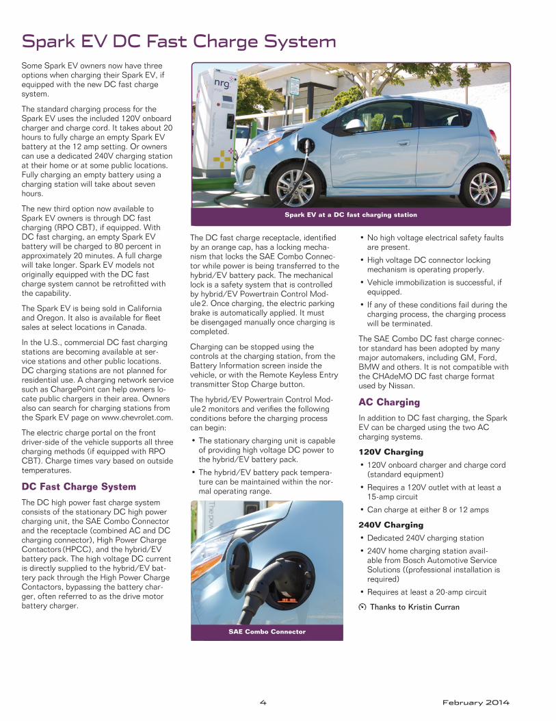
Some Spark EV owners now have three options when charging their Spark EV, if equipped with the new DC fast charge system .
The standard charging process for the Spark EV uses the included 120V onboard charger and charge cord . It takes about 20 hours to fully charge an empty Spark EV battery at the 12 amp setting . Or owners can use a dedicated 240V charging station at their home or at some public locations . Fully charging an empty battery using a charging station will take about seven hours .
The new third option now available to Spark EV owners is through DC fast charging (RPO CBT), if equipped . With DC fast charging, an empty Spark EV battery will be charged to 80 percent in approximately 20 minutes . A full charge will take longer . Spark EV models not originally equipped with the DC fast charge system cannot be retrofitted with the capability .
The Spark EV is being sold in California and Oregon . It also is available for fleet sales at select locations in Canada .
In the U .S ., commercial DC fast charging stations are becoming available at ser-vice stations and other public locations . DC charging stations are not planned for residential use . A charging network service such as ChargePoint can help owners lo-cate public chargers in their area . Owners also can search for charging stations from the Spark EV page on www .chevrolet .com .
The electric charge portal on the front driver-side of the vehicle supports all three charging methods (if equipped with RPO CBT) . Charge times vary based on outside temperatures .
DC Fast Charge System
The DC high power fast charge system consists of the stationary DC high power charging unit, the SAE Combo Connector and the receptacle (combined AC and DC charging connector), High Power Charge Contactors (HPCC), and the hybrid/EV battery pack . The high voltage DC current is directly supplied to the hybrid/EV bat-tery pack through the High Power Charge Contactors, bypassing the battery char-ger, often referred to as the drive motor battery charger .
The DC fast charge receptacle, identified by an orange cap, has a locking mecha-nism that locks the SAE Combo Connec-tor while power is being transferred to the hybrid/EV battery pack . The mechanical lock is a safety system that is controlled by hybrid/EV Powertrain Control Mod-ule 2 . Once charging, the electric parking brake is automatically applied . It must be disengaged manually once charging is completed .
Charging can be stopped using the controls at the charging station, from the Battery Information screen inside the vehicle, or with the Remote Keyless Entry transmitter Stop Charge button .
The hybrid/EV Powertrain Control Mod-ule 2 monitors and verifies the following conditions before the charging process can begin:
• The stationary charging unit is capable of providing high voltage DC power to the hybrid/EV battery pack .
• The hybrid/EV battery pack tempera-ture can be maintained within the nor-mal operating range .
• No high voltage electrical safety faults are present .
• High voltage DC connector locking mechanism is operating properly .
• Vehicle immobilization is successful, if equipped .
• If any of these conditions fail during the charging process, the charging process will be terminated .
The SAE Combo DC fast charge connec-tor standard has been adopted by many major automakers, including GM, Ford, BMW and others . It is not compatible with the CHAdeMO DC fast charge format used by Nissan .
AC Charging
In addition to DC fast charging, the Spark EV can be charged using the two AC charging systems .
120V Charging
• 120V onboard charger and charge cord (standard equipment)
• Requires a 120V outlet with at least a 15-amp circuit
• Can charge at either 8 or 12 amps
240V Charging
• Dedicated 240V charging station
• 240V home charging station avail-able from Bosch Automotive Service Solutions ((professional installation is required)
• Requires at least a 20-amp circuit
Thanks to Kristin Curran
Spark EV at a DC fast charging station
SAE Combo Connector
Spark EV DC Fast Charge System
February 2014 5
Speedometer Needle Accuracy
Supplement to High Feature V6 Engine Timing Procedure
Owners of some 2003-2014 Escalade models, Silverado, Suburban, Tahoe, Sierra and Yukon models; and the 2003-2013 Avalanche may comment that their vehicle's speedometer needle appears to be inaccurate . This may be noticed most often when comparing the speedometer to the optional digital speedometer readout displayed on the Driver Information Center .
The speedometer needle is electrically operated by a stepper motor and there may be some variation in accuracy . Digital readout devices, such as the digital speedometer on the Driver Information Center, are direct read-outs of the Vehicle Speed Sensor (VSS) and their accuracy is much greater . Tire size, tread life and inflation may cause some variation in the readings .
The specification for speedometer needle accuracy is +/– 2 MPH at any given speed when looking straight at the needle .
Thanks to James Will
The following models offer the available high feature 3 .6L V6 engine (RPO LY7, LLT, LFX, LF3), 2 .8L V6 engine (RPO LP1) or 3 .0L V6 engine (RPO LF1, LFW):
• 2013-2014 ATS, XTS
• 2012-2014 Impala
• 2010-2014 Camaro, Terrain
• 2009-2014 Traverse
• 2008-2014 Enclave, Equinox
• 2008-2012 Malibu
• 2008-2010 Vue
• 2008-2009 Torrent
• 2007-2014 CTS, SRX, Acadia, Lacrosse (Allure – Canada only)
• 2007-2011 STS
• 2007-2010 Outlook
• 2007-2009 G6, Aura
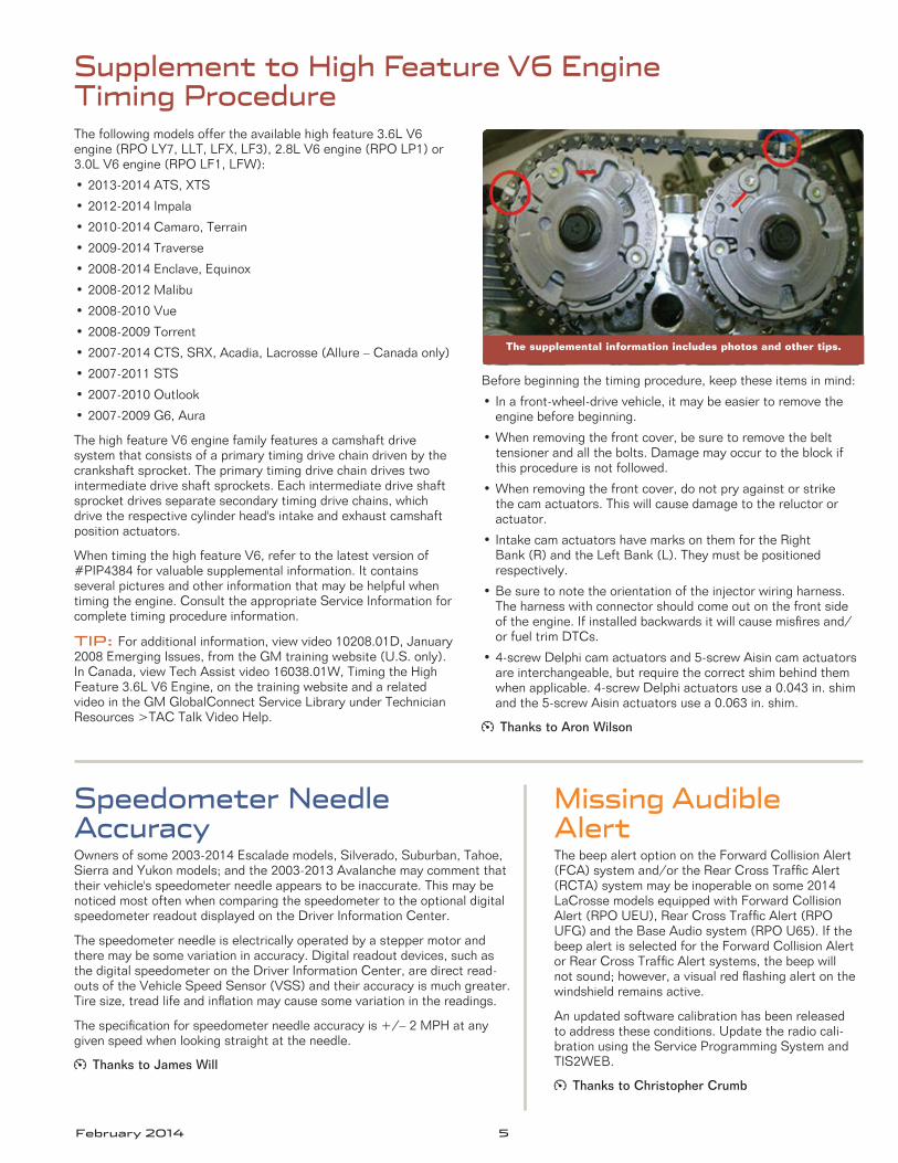
The high feature V6 engine family features a camshaft drive system that consists of a primary timing drive chain driven by the crankshaft sprocket . The primary timing drive chain drives two intermediate drive shaft sprockets . Each intermediate drive shaft sprocket drives separate secondary timing drive chains, which drive the respective cylinder head's intake and exhaust camshaft position actuators .
When timing the high feature V6, refer to the latest version of #PIP4384 for valuable supplemental information . It contains several pictures and other information that may be helpful when timing the engine . Consult the appropriate Service Information for complete timing procedure information .
TIP: For additional information, view video 10208 .01D, January 2008 Emerging Issues, from the GM training website (U .S . only) . In Canada, view Tech Assist video 16038 .01W, Timing the High Feature 3 .6L V6 Engine, on the training website and a related video in the GM GlobalConnect Service Library under Technician Resources >TAC Talk Video Help .
Before beginning the timing procedure, keep these items in mind:
• In a front-wheel-drive vehicle, it may be easier to remove the engine before beginning .
• When removing the front cover, be sure to remove the belt tensioner and all the bolts . Damage may occur to the block if this procedure is not followed .
• When removing the front cover, do not pry against or strike the cam actuators . This will cause damage to the reluctor or actuator .
• Intake cam actuators have marks on them for the Right Bank (R) and the Left Bank (L) . They must be positioned respectively .
• Be sure to note the orientation of the injector wiring harness . The harness with connector should come out on the front side of the engine . If installed backwards it will cause misfires and/or fuel trim DTCs .
• 4-screw Delphi cam actuators and 5-screw Aisin cam actuators are interchangeable, but require the correct shim behind them when applicable . 4-screw Delphi actuators use a 0 .043 in . shim and the 5-screw Aisin actuators use a 0 .063 in . shim .
Thanks to Aron Wilson
The supplemental information includes photos and other tips.
Missing Audible AlertThe beep alert option on the Forward Collision Alert (FCA) system and/or the Rear Cross Traffic Alert (RCTA) system may be inoperable on some 2014 LaCrosse models equipped with Forward Collision Alert (RPO UEU), Rear Cross Traffic Alert (RPO UFG) and the Base Audio system (RPO U65) . If the beep alert is selected for the Forward Collision Alert or Rear Cross Traffic Alert systems, the beep will not sound; however, a visual red flashing alert on the windshield remains active .
An updated software calibration has been released to address these conditions . Update the radio cali-bration using the Service Programming System and TIS2WEB .
Thanks to Christopher Crumb
6 February 2014
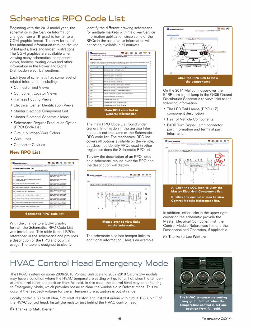
Schematics RPO Code ListBeginning with the 2013 model year, the schematics in the Service Information changed from a TIF graphic format to a CGM graphic format . The new format of-fers additional information through the use of hotspots, links and larger illustrations . The CGM graphics are available when viewing many schematics, component views, harness routing views and other information in the Power and Signal Distribution electrical sections .
Each type of schematic has some level of related information, including:
• Connector End Views
• Component Locator Views
• Harness Routing Views
• Electrical Center Identification Views
• Master Electrical Component List
• Master Electrical Schematic Icons
• Schematics Regular Production Option (RPO) Code List
• Circuit Number/Wire Colors
• Wire Lines
• Connector Cavities
New RPO List
With the change to a CGM graphic format, the Schematics RPO Code List was introduced . This table lists all RPOs referenced in the schematics and provides a description of the RPO and country usage . The table is designed to clearly
identify the different drawing schematics for multiple markets within a given Service Information publication since some of the RPOs in the schematics information will not being available in all markets .
The main RPO Code List found under General Information in the Service Infor-mation is not the same at the Schematics RPO code list . The mechanical RPO list covers all options available on the vehicle, but does not identify RPOs used in other regions as does the Schematic RPO list .
To view the description of an RPO listed on a schematic, mouse-over the RPO and the description will display .
The schematic also has hotspot links to additional information . Here’s an example .
On the 2014 Malibu, mouse-over the E4RR turn signal lamp in the G405 Ground Distribution Schematic to view links to the following information:
• The LED Tail Lamps (RPO 1LZ) component description
• Rear of Vehicle Components
• E4RR Turn Signal Lamp connector part information and terminal part information
In addition, other links in the upper right corner on the schematic provide the Master Electrical Component list, the Control Module References list, and the Description and Operation, if applicable .
Thanks to Lou Winters
Schematic RPO code list
Mouse-over to view links on the schematic.
Main RPO code list in General Information
Click the RPO link to view the components
A. Click the LOC icon to view the Master Electrical Component list.
B. Click the computer icon to view Control Module References list.
The HVAC temperature setting may go to full hot when the
temperature control is set one position from full cold.
The HVAC system on some 2006-2010 Pontiac Solstice and 2007-2010 Saturn Sky models may have a condition where the HVAC temperature setting will go to full hot when the temper-ature control is set one position from full cold . In this case, the control head may be defaulting to Emergency Mode, which provides hot air to clear the windshield in Defrost mode . This will occur if the feedback voltage for the air temperature actuators is out of range .
Locally obtain a 60 to 68 ohm, 1/2 watt resistor, and install it in-line with circuit 1688, pin F of the HVAC control head . Install the resistor just behind the HVAC control head .
Thanks to Matt Bierlein
HVAC Control Head Emergency Mode
February 2014 7
New Pinion Nut on 9.5/9.76 Inch Rear Axle
Do Not Swap Control Modules
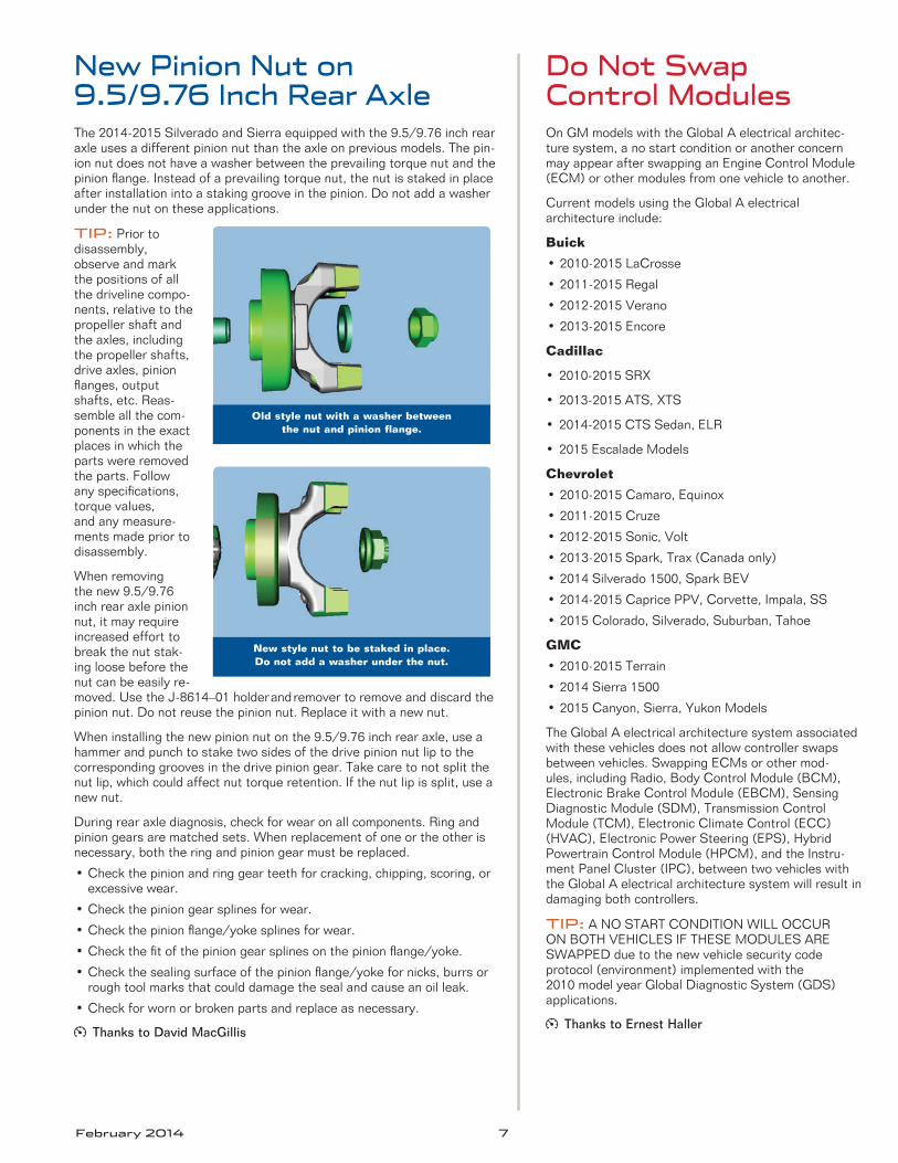
The 2014-2015 Silverado and Sierra equipped with the 9 .5/9 .76 inch rear axle uses a different pinion nut than the axle on previous models . The pin-ion nut does not have a washer between the prevailing torque nut and the pinion flange . Instead of a prevailing torque nut, the nut is staked in place after installation into a staking groove in the pinion . Do not add a washer under the nut on these applications .
TIP: Prior to disassembly, observe and mark the positions of all the driveline compo-nents, relative to the propeller shaft and the axles, including the propeller shafts, drive axles, pinion flanges, output shafts, etc . Reas-semble all the com-ponents in the exact places in which the parts were removed the parts . Follow any specifications, torque values, and any measure-ments made prior to disassembly .
When removing the new 9 .5/9 .76 inch rear axle pinion nut, it may require increased effort to break the nut stak-ing loose before the nut can be easily re-moved . Use the J-8614–01 holder and remover to remove and discard the pinion nut . Do not reuse the pinion nut . Replace it with a new nut .
When installing the new pinion nut on the 9 .5/9 .76 inch rear axle, use a hammer and punch to stake two sides of the drive pinion nut lip to the corresponding grooves in the drive pinion gear . Take care to not split the nut lip, which could affect nut torque retention . If the nut lip is split, use a new nut .
During rear axle diagnosis, check for wear on all components . Ring and pinion gears are matched sets . When replacement of one or the other is necessary, both the ring and pinion gear must be replaced .
• Check the pinion and ring gear teeth for cracking, chipping, scoring, or excessive wear .
• Check the pinion gear splines for wear .
• Check the pinion flange/yoke splines for wear .
• Check the fit of the pinion gear splines on the pinion flange/yoke .
• Check the sealing surface of the pinion flange/yoke for nicks, burrs or rough tool marks that could damage the seal and cause an oil leak .
• Check for worn or broken parts and replace as necessary .
Thanks to David MacGillis
On GM models with the Global A electrical architec-ture system, a no start condition or another concern may appear after swapping an Engine Control Module (ECM) or other modules from one vehicle to another .
Current models using the Global A electrical architecture include:
Buick
• 2010-2015 LaCrosse
• 2011-2015 Regal
• 2012-2015 Verano
• 2013-2015 Encore
Cadillac
• 2010-2015 SRX
• 2013-2015 ATS, XTS
• 2014-2015 CTS Sedan, ELR
• 2015 Escalade Models
Chevrolet
• 2010-2015 Camaro, Equinox
• 2011-2015 Cruze
• 2012-2015 Sonic, Volt
• 2013-2015 Spark, Trax (Canada only)
• 2014 Silverado 1500, Spark BEV
• 2014-2015 Caprice PPV, Corvette, Impala, SS
• 2015 Colorado, Silverado, Suburban, Tahoe
GMC
• 2010-2015 Terrain
• 2014 Sierra 1500
• 2015 Canyon, Sierra, Yukon Models
The Global A electrical architecture system associated with these vehicles does not allow controller swaps between vehicles . Swapping ECMs or other mod-ules, including Radio, Body Control Module (BCM), Electronic Brake Control Module (EBCM), Sensing Diagnostic Module (SDM), Transmission Control Module (TCM), Electronic Climate Control (ECC) (HVAC), Electronic Power Steering (EPS), Hybrid Powertrain Control Module (HPCM), and the Instru-ment Panel Cluster (IPC), between two vehicles with the Global A electrical architecture system will result in damaging both controllers .
TIP: A NO START CONDITION WILL OCCUR ON BOTH VEHICLES IF THESE MODULES ARE SWAPPED due to the new vehicle security code protocol (environment) implemented with the 2010 model year Global Diagnostic System (GDS) applications .
Thanks to Ernest Haller
Old style nut with a washer between the nut and pinion flange.
New style nut to be staked in place. Do not add a washer under the nut.

8 February 2014
Cold weather, and there has been a lot of it across the country recently, can affect a vehicle’s performance in many ways . A recent TechLink article covered how the different compounds of various winter, summer and all-season tires can result in varying degrees of tire noise . For high performance summer-only tires, cold temperatures can cause actual tire damage .
TIP: The special tread and compounds used on high performance summer-only tires will cause a decrease in performance and reduced traction in cold climates with temper-atures below approximately 40°F (5°C) . GM recommends installing winter tires if driving below these temperatures .
If temperatures drop below 20°F (−7°C), GM recommends avoiding driving, moving, or test-driving vehicles equipped with high performance summer-only tires as operating at these temperatures can cause damage to the tires .
The rubber used in these tires loses flexibility and may develop surface cracks in the tire tread/shoulder area at colder temperatures . Surface cracks are cosmetic and will not result in a loss of air . However, the cracking is damaging to the tire . Tires that have been used in cold climates and exhibit tread cracks should be discarded .
The models listed in the chart are all equipped with 3-season performance tires commonly referred to as summer tires . These tires should not be driven if temperatures are below 20°F (−7°C) .
Tire Storage
Summer tires should be stored indoors at temperatures above 20°F (-7°C) when not in use . If the tires have been subjected to 20°F (-7°C) or less, let them warm up in a heated space to at least 40°F (5°C) for 24 hours or more before being installed or driving a vehicle on which they have been installed . Inflate the tires only after they have been warmed above 40°F (5°C) .
Do not place tires near heaters or heating devices used to warm the room where the tires are stored . Do not apply heat or blow heated air directly on the tires . Always inspect tires before use after being stored .
Refer to the latest version of Bulletin #04-03-10-013 for in-formation on available winter tires for cold climate operation or call the GM Tire Program at 1-877-728-4737 (U .S . only) for help with late season tire availability or substitutions .
Thanks to David MacGillis
Tire Cold Weather Cracking
Cracking from cold weather
2012-2014 Regal GS
The Regal GS is available with P255/35R20 summer tires .
2014 CTS Vsport
The CTS VSport is equipped with 245/40R18 and 275/35R18 Pirelli P-Zero Nero (RPO RKK) ultra-high performance summer tires .
2012-2014 Camaro Models (RPO ZL1, 1LE or Z/28)
The Camaro ZL1 and RPO 1LE models come with 285/35ZR20 and/or 305/35ZR20 Goodyear F1 Supercar G2 D .O .T . approved ultra high performance, track capable summer tires . The Camaro Z/28 is equipped with 305/30ZR19 Pirelli P Zero Trofeo R of similar capabilities .
2014 Corvette, Corvette Z51
The 2014 Corvette is equipped with Michelin Pilot Super Sport ZP Run-flat tires . This tire is an ultra high performance, track capable summer tire .
2014 SS The SS is equipped with Bridgestone ultra-high performance summer tires .
On some 2013 Malibu models equipped with the Passive Entry System (RPO ATH) that were built prior to January 1, 2013, the passive door locking feature may not function when the vehicle is exited even though the system has been enabled by the owner .
A new calibration has been released for the Body Control Module (BCM) to enable the feature . Using SPS, repro-gram the BCM with the latest calibration available in TIS2Web .
After programming, verify the Passive Lock feature is activated by performing the following procedure (also covered in the Vehicle Personalization section of the appropriate Service Information):
1 . Press CONFIG, and then select Vehicle Settings to access the personalization menu .
2 . Select the Remote Lock, Unlock, Start menu item .
3 . Turn the Tune/Menu knob to highlight Passive Door Lock .
4 . Press the Tune/Menu knob to select Passive Door Locking .
5 . Turn the Tune/Menu knob to highlight Off, On, or On with Active Horn Chirp .
6 . Press the Tune/Menu knob to select the setting and return to the last menu .
Confirm the feature is functioning by turn-ing the vehicle off, removing the key fob
from the vehicle, and closing all doors .
The vehicle doors should lock eight seconds after moving the key fob away from the vehicle .
Thanks to Christopher Crumb
Passive Door Locking Does Not Function
Select Remote Lock, Unlock, Start to access the Passive Door Locking feature.
February 2014 9
GM TechLink is published for all GM retail technicians and service consultants to provide timely information to help increase know ledge about GM products and improve the performance of the service department .
Publisher:John Meade GM Customer Care and Aftersales
Editor:Lisa G. Scott GM Customer Care and Aftersales
Technical Editor:Mark Spencer /mspencer@gpstrategies .com
Production Manager:Marie Meredith
Graphic Design:5by5 Design LLC/dkelly@5by5dzign .com
FAX number: 3 1-248-729-4704
Write to: * TechLinkPO Box 500Troy, MI 48007-0500
GM TechLink on the Web: : GM GlobalConnectGeneral Motors service tips are intended for use by professional technicians, not a “do-it-yourselfer .” T hey are written to inform those technicians of conditions that may occur on some vehicles, or to provide information that could assist in the proper service of a vehicle . Properly trained technicians have the equipment, tools, safety instructions and know-how to do a job properly and safely . If a condition is described, do not assume that the information applies to your vehicle or that your vehicle will have that condition . See a General Motors dealer servicing your brand of General Motors vehicle for information on whether your vehicle may benefit from the information .Inclusion in this publication is not necessarily an endorsement of the individual or the company .
Copyright© 2014 General Motors All rights reserved .
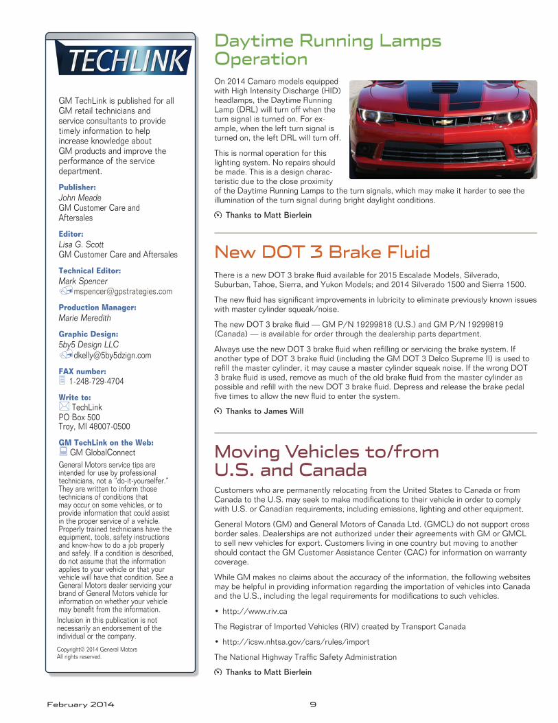
Daytime Running Lamps OperationOn 2014 Camaro models equipped with High Intensity Discharge (HID) headlamps, the Daytime Running Lamp (DRL) will turn off when the turn signal is turned on . For ex-ample, when the left turn signal is turned on, the left DRL will turn off .
This is normal operation for this lighting system . No repairs should be made . This is a design charac-teristic due to the close proximity of the Daytime Running Lamps to the turn signals, which may make it harder to see the illumination of the turn signal during bright daylight conditions .
Thanks to Matt Bierlein
New DOT 3 Brake Fluid
Moving Vehicles to/from U.S. and Canada
There is a new DOT 3 brake fluid available for 2015 Escalade Models, Silverado, Suburban, Tahoe, Sierra, and Yukon Models; and 2014 Silverado 1500 and Sierra 1500 .
The new fluid has significant improvements in lubricity to eliminate previously known issues with master cylinder squeak/noise .
The new DOT 3 brake fluid — GM P/N 19299818 (U .S .) and GM P/N 19299819 (Canada) — is available for order through the dealership parts department .
Always use the new DOT 3 brake fluid when refilling or servicing the brake system . If another type of DOT 3 brake fluid (including the GM DOT 3 Delco Supreme II) is used to refill the master cylinder, it may cause a master cylinder squeak noise . If the wrong DOT 3 brake fluid is used, remove as much of the old brake fluid from the master cylinder as possible and refill with the new DOT 3 brake fluid . Depress and release the brake pedal five times to allow the new fluid to enter the system .
Thanks to James Will
Customers who are permanently relocating from the United States to Canada or from Canada to the U .S . may seek to make modifications to their vehicle in order to comply with U .S . or Canadian requirements, including emissions, lighting and other equipment .
General Motors (GM) and General Motors of Canada Ltd . (GMCL) do not support cross border sales . Dealerships are not authorized under their agreements with GM or GMCL to sell new vehicles for export . Customers living in one country but moving to another should contact the GM Customer Assistance Center (CAC) for information on warranty coverage .
While GM makes no claims about the accuracy of the information, the following websites may be helpful in providing information regarding the importation of vehicles into Canada and the U .S ., including the legal requirements for modifications to such vehicles .
• http://www .riv .ca
The Registrar of Imported Vehicles (RIV) created by Transport Canada
• http://icsw .nhtsa .gov/cars/rules/import
The National Highway Traffic Safety Administration
Thanks to Matt Bierlein
10 February 2014
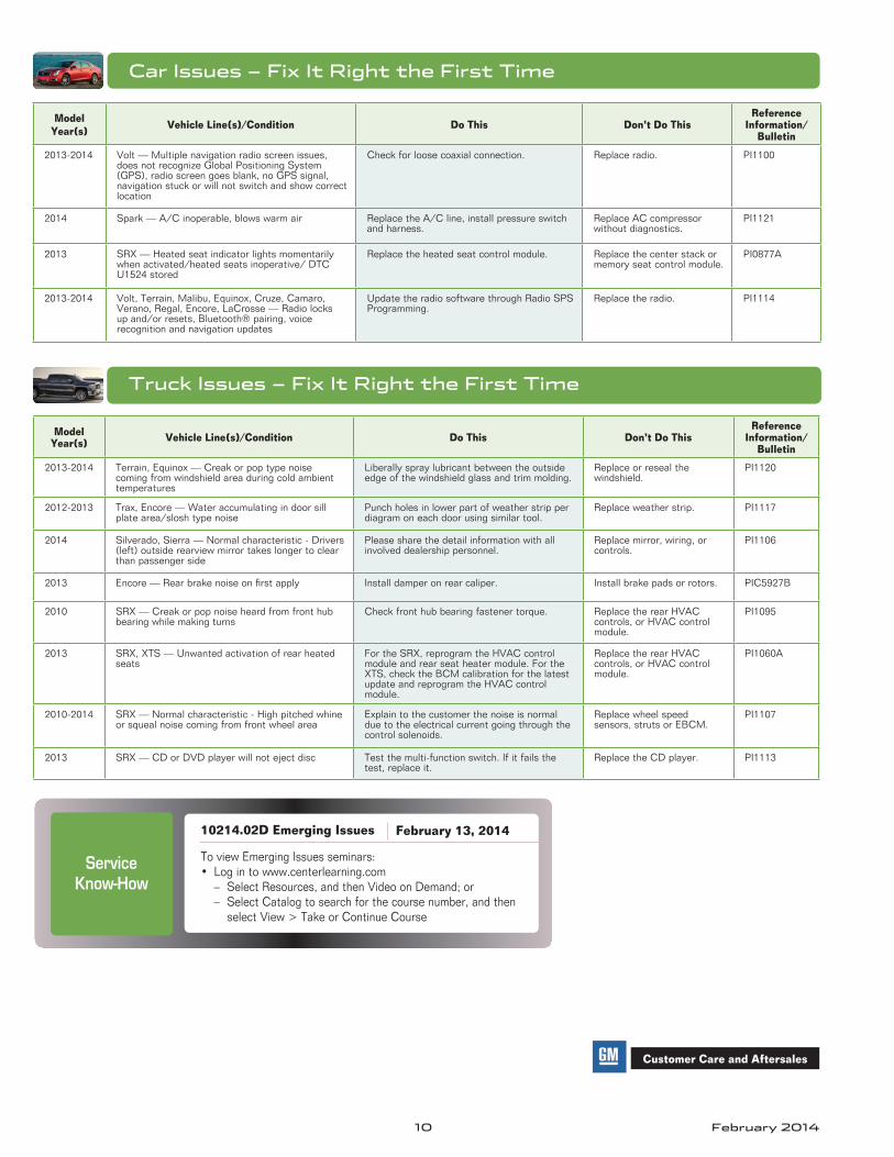
Car Issues – Fix It Right the First Time
Model Year(s) Vehicle Line(s)/Condition Do This Don’t Do This
Reference Information/
Bulletin
2013-2014 Volt — Multiple navigation radio screen issues, does not recognize Global Positioning System (GPS), radio screen goes blank, no GPS signal, navigation stuck or will not switch and show correct location
Check for loose coaxial connection . Replace radio . PI1100
2014 Spark — A/C inoperable, blows warm air Replace the A/C line, install pressure switch and harness .
Replace AC compressor without diagnostics .
PI1121
2013 SRX — Heated seat indicator lights momentarily when activated/heated seats inoperative/ DTC U1524 stored
Replace the heated seat control module . Replace the center stack or memory seat control module .
PI0877A
2013-2014 Volt, Terrain, Malibu, Equinox, Cruze, Camaro, Verano, Regal, Encore, LaCrosse — Radio locks up and/or resets, Bluetooth® pairing, voice recognition and navigation updates
Update the radio software through Radio SPS Programming .
Replace the radio . PI1114
Truck Issues – Fix It Right the First Time
Model Year(s) Vehicle Line(s)/Condition Do This Don’t Do This
Reference Information/
Bulletin
2013-2014 Terrain, Equinox — Creak or pop type noise coming from windshield area during cold ambient temperatures
Liberally spray lubricant between the outside edge of the windshield glass and trim molding .
Replace or reseal the windshield .
PI1120
2012-2013 Trax, Encore — Water accumulating in door sill plate area/slosh type noise
Punch holes in lower part of weather strip per diagram on each door using similar tool .
Replace weather strip . PI1117
2014 Silverado, Sierra — Normal characteristic - Drivers (left) outside rearview mirror takes longer to clear than passenger side
Please share the detail information with all involved dealership personnel .
Replace mirror, wiring, or controls .
PI1106
2013 Encore — Rear brake noise on first apply Install damper on rear caliper . Install brake pads or rotors . PIC5927B
2010 SRX — Creak or pop noise heard from front hub bearing while making turns
Check front hub bearing fastener torque . Replace the rear HVAC controls, or HVAC control module .
PI1095
2013 SRX, XTS — Unwanted activation of rear heated seats
For the SRX, reprogram the HVAC control module and rear seat heater module . For the XTS, check the BCM calibration for the latest update and reprogram the HVAC control module .
Replace the rear HVAC controls, or HVAC control module .
PI1060A
2010-2014 SRX — Normal characteristic - High pitched whine or squeal noise coming from front wheel area
Explain to the customer the noise is normal due to the electrical current going through the control solenoids .
Replace wheel speed sensors, struts or EBCM .
PI1107
2013 SRX — CD or DVD player will not eject disc Test the multi-function switch . If it fails the test, replace it .
Replace the CD player . PI1113
Customer Care and Aftersales
Service
Know-How
10214.02D Emerging Issues
To view Emerging Issues seminars:• Log in to www .centerlearning .com
– Select Resources, and then Video on Demand; or – Select Catalog to search for the course number, and then
select View > Take or Continue Course
February 13, 2014