Embed Size (px)
Citation preview

cc
08FeatureEver wondered how to optimiseyour USBL positioning system?Sonardyne explains how
THE
CU
STO
MER
MA
GA
ZIN
E FR
OM
SON
ARD
YN
EIS
SUE
2
16TechnologyJonathan Martin talks to Baseline about the challengesof bringing Lodestar to market
22ProductionThe people and processesinvolved in meeting record levelsof demand
26Case StudySonardyne Wideband onboardthe World's largest crane vesselin the Gulf of Mexico
Baseline

cc
Is Your Underwater Perimeter Secure?Sentinel Intruder Detection SonarSentinel is a new Intruder Detection Sonar designed for the protection of marine assets fromunderwater attack. Small and lightweight, Sentinel can be easily and quickly deployed in avariety of scenarios including: seafloor, jetty or from over the side of a vessel.
From a single node, Sentinel can be expanded into a fully networked solution with multipleheads that can be integrated into a remote Command and Control system that forms a securecost-effective perimeter. Sentinel’s automated detection, classification and tracking software isproven to minimise false alarms by ensuring only genuine threats trigger an alert. Find out howSentinel can protect your underwater perimeter, visit www.sonardyne.com
cc
04 News Products and People08 Feature USBL System Optimisation14 Photo Story Sound Surveyor Launch15 Hardware Focus On Transponders16 Technology Lodestar20 Case Study Shallow Water Construction
22 Our People Production Department26 Case Study Thialf Installation28 Technology DTU and SIPS Inline Unit30 International News around theworld31 Help & Advice Ask Dave
CO
NTE
NTS
BASE
LIN
EIS
SUE
2
14
08
16
Front CoverA buoy-mounted surfacetransceiver,part of Sonardyne’sTsunami Detection System.When an alert is triggered,an Inmarsat-C satellite terminalon the buoy relays data to ashore station from wherewarnings can be issued.
Back CoverA 5,000 metre rated subseaLodestar AHRS unitmanufactured from Ferralium.Turn to Page 16 for the storyof its development.
Marketing ManagerDavid Brown
Marketing Co-ordinatorAndrew Covey
Strategic Developmentand Marketing DirectorRob Balloch
Art DirectorMichael Lindley at TruthStudiowww.truthstudio.co.uk
PhotographyAstonleigh Studios,Alton,Hampshire, UKwww.astonleighstudio.co.uk(Pages 04, 05, 16, 18, 22, 24,25, 28, 29 and 31).
Baseline Magazine is editedby Rob Balloch with DavidBrown and Andrew Covey.
Published by SonardyneInternational Ltd. BlackbusheBusiness Park,Yateley,Hampshire GU46 6GD.United Kingdom.© Sonardyne InternationalLtd 2007.www.sonardyne.com
No part of this magazinemay be reproduced withoutpermission of the publisher.Colour repro by ProCo PrintLtd. Printed by ProCo PrintLtd. Every effort is made toensure that information iscorrect at time of goingto press.
WELCOME BACK TO Baseline, Sonardyne’s regular magazine
that presents the latest news, technology and insights into
our products and capabilities.
Since Issue 1, we’ve successfully launched Lodestar, our
new Inertial Navigation System. On Page 16, you can learn
more about the development of this exciting new product in
an interview with key members of the Lodestar engineering team.
In a detailed feature article starting on Page 08, we explain to users of USBL
systems how they can best optimise the performance from their equipment to ensure
success.The quality of reference sensors and deployment methods are amongst the
factors discussed.
Sentinel Intruder Detection Sonar (Page 07), is yet another example of the record
levels of investment the company is making at the moment. Designed to counter the
threat of underwater attacks against ships, ports and offshore installations, Sentinel is
the first of a new generation of maritime security products to be released by Sonardyne.
Unprecedented demand combined with almost impossible delivery deadlines.
Find out more about the challenges Operations Director Tim Moore and his team face
on Page 22.
Of course, we are not forgetting the continual development of Sonardyne
Wideband™. By far the largest single R&D effort is dedicated to developing improved
positioning capabilities that will enable us to deliver trusted solutions to all of our core
oil and gas markets now and well into the future.
As Baseline Issue 2 goes to press, we’re already on the look out for interesting
stories to bring you in Issue 3, until then, best wishes.
Rob Balloch, Editor
26
22

04 Baseline » Issue 2
NEWS
cc
OUR PEOPLE
Richard Binksrejoins the teamI rejoined Sonardyne as Sales Director in
May this year! Sonardyne has seen
tremendous growth so it’s a fair question
as to why they needed my skills if they were
doing so well in my absence!
Part of the answer is about
understanding where we are on the offshore
industry’s typical cycles of boom and bust.
Current large forward order books are
difficult to see beyond, but a longer term
market vision is essential.This requires
a two way dialogue with our customers,
so hopefully I will be talking to many of
you directly.
Sonardyne has not only grown but
continues to build on its core skill set with
Gyro,Inertial and Sonar technologies.
Across all our busy offshore product sectors
we are seeing both demand and increasing
windows of opportunity. The growing
success story is Wideband with accuracies
at MF now setting new bench marks and
allied robust telemetry offering potential in
subsea control and integrated solutions.
“Sonardyne has not onlygrown but continues tobuild on its core skill set”
Going back to the industry “cycles”,
its definitely still boom!! We cannot throw
caution to the wind,but my role in quantifying
the market,will ensure that a “caution” factor
does not limit our resources.One thing I do
need, is a new crystal ball so if you still have
a clear one,please send it to me!!
Allseas choose Widebandfor KG-D6 Indian fielddevelopmentSonardyne Wideband continues to be the
positioning technology of choice for the
Swiss-based pipelay specialist Allseas Group.
The company’s latest order is for Long
BaseLine (LBL) hardware that includes a
substantial quantity of Wideband Compatt
5 acoustic transponders and five Data
Fusion Engines that will be used to support
both LBL and Ultra-Short BaseLine (USBL)
subsea positioning operations.Two of
Sonardyne’s recently launched subsea
Lodestar attitude and heading reference
units have also been ordered and will be
used to aid the high accuracy installation
of structures on the seabed.
Allseas has specified that all of the
subsea equipment be rated to 5,000 metres
operating depth. Commenting on this
decision, Sonardyne’s Derek Donaldson
said:“This reflects Allseas’ belief that future
contracts will find them operating in
increasingly deeper waters. By investing in
appropriate acoustic positioning technology
now, the company believes that they can
future-proof their investment offering them
a competitive advantage when bidding for
complex deepwater operations.”
The new equipment will initially be
used to provide field wide positioning for
the Allseas fleet mobilised on the KG-D6
project for Reliance offshore India.Although
this work is expected to take place in water
depths averaging 1,000 metres,Allseas
surveyors anticipate that the size of the
project will result in considerable acoustic
congestion brought about by multiple
vessels operating within close proximity to
each other.“Overcoming this was a major
driver in the choice of Sonardyne
Wideband as the technology provides over
200 non-interfering navigation channels”
added Derek.
The use of Sonardyne’s unique ‘ping
stacking’ acoustic interrogation technique
was also said to be an influencing factor.
The method enables the USBL system to
transmit acoustic interrogations to subsea
transponders before the last reply was
received.This enables the operator / vessel
DP system to receive a position update
every second regardless of water depth.
Whilst ping stacking will not be used on the
initial deployment of the equipment in India
it will offer significant advantages when
installing structures in ultra deep water.
The Sonardyne equipment will be
mobilised onto vessels including Allseas’
new vessel Audacia, deepwater pipelay
vessel Lorelay and Highland Fortress
pipeline survey vessel. Solitaire, the World’s
largest pipelay vessel, was also upgraded
to Fusion Wideband USBL earlier in the year.

Baseline » Issue 2 05
Scout USBL has a new aluminium bronze
transceiver now supplied as standard.
The new design is shorter, more rugged
and offers dramatically better corrosion
resistance making it suitable for longer
term deployment. The design also offers
better protection to the transducer, and as
most Scouts are used as portable systems,
it comes with a collar to protect the
transducer during installation and storage
on or off the vessel.
The new mechanics, and recently
introduced easy to use software for Scout,
shows Sonardyne’s commitment to the
continuous improvement of its products.
Are you looking for a new career
challenge? Here at Sonardyne, we’re
always looking for highly motivated
and talented individuals to join our
team.Our website has details of how
to contact our HR department, together
with a list of current vacancies.
Aberdeen-based NCS Survey Ltd has
made its first major investment in
Sonardyne Wideband LBL. Formed in June
2005, NCS Survey has become the fastest
growing independent survey company in
the sector and has until now utilised
acoustic equipment hired in from rental
companies to support its activities.
Commenting on the order,Andy Gray,
managing director of NCS, said “We have
used Sonardyne equipment successfully on
subsea projects on many occasions and felt
that the time was now right for us to make
the investment.” He added “Our business is
expanding steadily and having our own LBL
equipment will give us greater flexibility
and the freedom to serve our clients even
more effectively.”
Pictured left to right during the Ocean BusinessExhibition in March:John Ramsden (Sonardyne),Chris Erni (NCS) and Derek Donaldson(Sonardyne)
Orange DPT transponders shown mounted on BOP and riser
New Scout USBLTransceiver
DEEP WATER DRILLING
Hakuryu 5 upgrades to MRAMS
NCS Survey invests in Wideband LBL
OUR PEOPLE
In a truly international
operation, Japan Drilling
have upgraded their
acoustic riser angle system
onboard the Hakuryu 5
to Ranger MRAMS.The
system is Sonardyne’s latest
generation Marine Riser
Angle Monitoring System
and utilises Wideband
signal technology to
provide robust telemetry
and riser/BOP positioning.
The MRAMS system
was shipped to the rig when
it was in the US, but was not
actually installed until May
when it was in dry dock in
Singapore.The rig then
sailed to Japan where,in
July,Sonardyne engineer
Nge Aik Moh set the system
to work and provided
operator training.
The rig’s crew were
reported to be impressed
by the ease of use of the
system and the reliability of
the BOP/riser angular data
provided by the wideband
telemetry signals.

06 Baseline » Issue 2
NEWS
cc
PROJECT UPDATE
Tsunami system on watchin the Bay of Bengal
The Sonardyne tsunami detection system underwent stringent testing at the acoustic tank facility at NIOT, Chennai.Senior project engineer Nick Street fromSonardyne (pictured above) and Rangarajan from Elektronik Lab accompanied the NIOT team during the launch of the system
As Baseline goes to press,we’ve just heard that
our newly installed tsunami system successfully
detected a tsunami wave created by an
earthquake registering 6.2 on the Richter Scale
in the Bay of Bengal shortly before midnight
on 25th July.
In the last edition of Baseline, we reported
on the development of a system from
Sonardyne that is the first link in a chain of
communication systems that provide early
warning of an approaching tsunami wave.
Developed in response to the devastating
effects of the 2004 Indian Ocean Tsunami,
the Sonardyne system is based upon a
Compatt 5 subsea transponder that uses
the latest Wideband acoustic signal
technology to provide dependable
communications through deep water.
If the Compatt detects the change in
water pressure that results from the minute
variation in sea level (as little as 1 centimetre
in 4000 metres depth depending on the
algorithm used) following an earthquake
in the deep ocean, and which travels at
hundreds of kilometres per hour and
providing a tsunami warning. It also reduces
the Compatt’s power consumption which
enables it to remain in continuous monitoring
mode on the seabed for up to four years.
Commenting on the installation,
Rangarajan from Elektronik Lab said:
“As a soon as the Compatts were on the
seabed, they began their standard tsunami
reporting sequence.That gave the NIOT
team onboard a great deal of confidence
in the Sonardyne technology and its
capabilities” he added.
perhaps leads to a 10 metre high tsunami
wave on a distant beach.
Following side-by-side trials of
competing systems in late 2006 and early
2007, the National Institute of Ocean
Technology of India (NIOT) chose
Sonardyne’s tsunami detection system for
its Bay of Bengal monitoring programme.
In March, engineers travelled to India to
oversee the deployment of the first two
systems in 2,700 metres and 3,500 metres
water depth. Over the coming months, a
further eight systems will be deployed in
the region to establish a complete network
of tsunami monitoring stations.
The use of Sonardyne’s new intelligent
Wideband technology has made it possible
for NIOT to increase the efficiency of the
through-water communication needed when
...STOP PRESS:TSUNAMI UPDATE...STOP PRESS TS

Baseline » Issue 2 07
Sonardyne chose the Underwater Defence
Technology exhibition in Naples, Italy to
reveal to a surprised audience its new
Intruder Detection Sonar (IDS), Sentinel.
Designed to counter the threat of underwater
attacks against ships, harbours, coastal
industrial installations and offshore oil
platforms, the introduction of Sentinel follows
a major investment in engineering and
acoustic technology to create the world’s
smallest and best performing underwater
intruder detection sonar.
With a sonar head measuring just
44 centimetres tall by 33 centimetres
diameter, the Sentinel sonar array is
considerably smaller than any other system
currently available. It nevertheless provides
a full 360 degrees of coverage and is
capable of reliably detecting underwater
targets up to 900 metres away.Weighing just
35 kilogrammes the system can be
deployed in many different ways, including
over the vessel’s side, mounted rigidly or
in a seabed frame.
The reliable detection of underwater
targets and their discrimination from marine
mammals is a notoriously difficult problem.
Sentinel overcomes this challenge by
combining state-of-the-art sonar
technology, commercial off-the-shelf
(COTS) processing units and automated
detection, classification and tracking
software.This has been proved in extensive
trials over the past year to confirm a system
that can work in a wide range of difficult
acoustic underwater environments while
ensuring that only genuine threats are
highlighted.This minimises false alarms
and reduces the dangerous tension that
these can generate.
With maritime facilities such as oil
and gas refineries, LNG terminals, power
stations and oil platforms already deploying
conventional terrestrial security systems,
including thermal imaging, radar and
ground sensing devices, Sentinel now
closes the defensive circle.
Commenting on the launch of Sentinel,
Rob Balloch said,“Sentinel is the first of
a new generation of maritime security
products to be released by Sonardyne.We
have brought together many of the leading
experts in their specialised disciplines
to develop the unique technology that can
deliver trusted solutions to the customer
in the most challenging underwater
conditions such as noisy, shallow harbours.
We have listened to what the customers
really wanted from a diver detection system
and believe Sentinel is the first practical,
cost-effective solution to the threat presented
by underwater intruders.”
SOFTWARE UPDATE
Major CASIUSupdate released
Sonardyne’s Rob Balloch and Andy Meecham pictured with the Sentinel sonar head and commandworkstation during the UDT exhibition in Naples in June this year
PRODUCT LAUNCH
Sonardyne causes a stirwith Sentinel IDS
A completely new version of CASIUS, a
software tool used with Sonardyne’s USBL
systems, is now available offering substantial
improvements over the previous version.
CASIUS was introduced by Sonardyne
to independently verify the accuracy of
USBL systems and simultaneously calibrate
them by resolving the alignment errors
between the acoustic transceiver, the
vessel’s motion sensors and GPS antenna.
The new software is now totally
integrated into Ranger and Scout USBL
software as part of the easy to use
Calibration Wizard. Excel is no longer
needed, processing is almost
instantaneous, corrections are automatically
applied, client reports are supplied in pdf
format and no addtional security dongle is
required. In Fusion USBL, CASIUS runs as a
separate application with the same features.
For more information about the new
version of CASIUS, or to arrange an
upgrade, please email our customer
support team at [email protected]

Installation of a Sonardyne Type8021 USBL transceiver on anover-the-side deployment pole
08 Baseline » Issue 2
Technology
Optimising USBL
cc

Optimising theperformance ofyour USBL systemThe USBL positioning technique is highly convenient,enabling positioning of a large number of subsea targetsover a wide range of geometries and water depths andall from the surface vessel. The downside is that there area number of sources of error and care needs to be takento ensure system design, configuration and userunderstanding mitigate as many of these as possible.When this is achieved remarkable performance can result.Baseline talks to Simon Partridge, Engineering Director,to discover more.
Baseline » Issue 2 09
1Precision, bias and accuracyIt is very important to understandthese words. USBL systems can behighly precise but inaccurate dueto systematic biases or they canbe accurate but imprecise due
to random errors (see diagram overleaf). Onlyby understanding the nature of the error, canyou hope to begin to resolve it.
2Signal to NoisePositioning quality is hugelyeffected by the level ofsignal from the target beingtracked compared with thebackground noise level
seen by the USBL transceiver (SNR) below thevessel. Decreasing SNR causes increasingrandom error.
The noise from thrusters and machineryonboard varies tremendously from vessel-to-
vessel and tends to increase in heavierweather conditions as thrusters are moreactive. Sonardyne has developed a rangeof different USBL vessel transceivers whichare designed with increasing capability forrejecting vessel noise. Choosing the righttransceiver for the vessel and applicationis important.
Choosing the right transponder is criticaltoo. The higher the output power the greaterthe SNR. This either improves the systemperformance or increases the operating range.Increasing the output power reduces batterylife, and so choosing a transponder that hassufficient output power to ensure low randomerrors, while providing sufficient battery lifeis important.
Sonardyne’s family of Widebandtransponders can increase the SNR withouthaving to increase the peak power level andtherefore size of the transponder. In addition >>
USBL PositioningUltra-Short BaseLine positioning systemscalculate the position of a subsea targetby measuring the range and bearing ofa transponder from the vessel

10 Baseline » Issue 2
Technology
Optimising USBL
cc
directional transducers focus the valuable signaltowards the USBL system rather than wastingenergy when operating in deep water or atlong ranges.
3ElevationWhen a transponder is underthe vessel, the estimation ofdepth is extremely good,provided the averagesound velocity (SV) through
the water column is accurate, as mainlyderived from the range measurement.
When the transponder is at higherelevations, the azimuth or bearing estimationremains very good but the elevation estimationdegrades. However this can easily be mitigatedby using depth aiding, for example, byconfiguring the system to use the depth sensorsfitted to most Sonardyne transponders.
4RefractionUSBL systems measure boththe range and direction toa transponder.
The range measurementcan be affected by changes
in the effective SV throughout the water column.Refraction causes the signal path to bend asthe sound speed changes, which means thatthe measured distance will have a bias error.This is a particular issue when tracking atransponder at a high elevation angle and overlong range, as the time that the signal spendsin each sound speed layer will vary accordingto the angle that it meets that layer.
When tracking a transponder mainly belowthe vessel, refraction is minimal so an averagesound speed can be used with little problem.
Refraction does not affect the estimate ofhorizontal direction, however, it does causethe estimated elevation of the transponder tobe in error, since the USBL system is measuringthe direction of arrival at the transceiver andnot the true direction to the transponder.
When operating at high elevations andlong ranges, for example when tracking atowfish at a long layback, depth aiding willreduce both the random and systematic errorsthat arise.
In addition, if an SV profile is available,then the USBL system can correct for thesystematic refraction errors. It is important,
Random error (red cone):Causes position scatteraround the true beacon positionSystematic error (green cone):Causes positionscatter to be biased away from the true beaconposition
Elevation:The green cone illustrates an area of60 degrees below the vessel’s USBL tranceiver.Outside of this area, it is recommendedtransponder depth aiding is used
Refraction:A sound speed profile showing thevariation of speed of sound with depth

Baseline » Issue 2 11
however, when using SV profiles to be awarethat profiles can change within the operatingarea. SV profiles can change significantly atdifferent stages of the tide and between dayand night. Using an inaccurate SV profile cancause greater errors than just using an averagesound speed figure.
5Reference sensorsUSBL systems need to removethe huge effects of vesselmotion. To do this they useheading, pitch and roll motionsensors on the vessel. These
come in a variety of types, ages and cost. Thequality of these can dramatically limit positioningquality by introducing random error and bias.The better the sensor and installation, the betterthe performance of the total system.
Sonardyne USBL systems support a widerange of industry standard motion sensors.However, it is important to make sure that theaccuracy of sensor installed is appropriateto the accuracy required and the water depth.If operating mainly below the vessel then pitchand roll is critical. If more out to the side, forexample towfish tracking, the accuracy ofheading sensors is more critical.
Older sensors tend to be of poorer qualityand can cause errors due to data latency.Analogue output sensors can introduce scalingand sign convention error, and so it is importantto make sure that these are set-up correctly.
Users need to make sure the sensors arerigidly mounted and fitted as near to theroll/pitch centre of the vessel as practical andthat they are compensated by GPS velocityand heading inputs if appropriate. Watch outfor filter settings in the sensors which can overfilter data and introduce latency. If the latencyis known, Sonardyne USBL systems can be set-up to compensate.
If a separate pitch and roll sensor (VRU)and heading sensor are used (Gyro) then itis important that the two reference frames arealigned within a degree or so or errors canresult. This is the significant advantage ofintegrated heading and attitude sensors.
Sonardyne can now provide a premiumquality heading and attitude sensor of its owncalled Lodestar which is specifically designedto compensate USBL systems for vessel motion.(Turn to page 16 for more information).>>
(Above) Dual Lodestar units installed on a vessel for highlatitude trials in northern Norway.The unit comprises of sixsensing elements, three Ring Laser Gyros (RLG) and threeLinear Accelerometers, running a Sonardyne developedgyrocompass algorithm
(Left) With iUSBL systems, the transceiver is installed on theROV or towed vehicle and requires motion compensationfrom subsea AHRS
(Below) A subsea gyro installed directly above a USBL transceiveron an over-the-side deployment pole

cc
12 Baseline » Issue 2
Technology
Optimising USBL
6USBL transceiverdeploymentThe deployment of theUSBL transceiver is critical.It should ideally be rigidlymounted to the vessel well
below the keel away from any weatheror vessel induced aeration.
The motion compensation sensor shouldbe mounted at the roll/pitch centre of the vesselwhere it is subject to the least motion inducedacceleration. Sonardyne supply through-hulldeployment systems that are extremely rigidand ideal for high accuracy USBL positioningin deep water.
It is not always practical, however, to installsuch a permanent deployment system andother alternatives are required. Manyoperational installations have shown that ifcare is taken then moon pool and over-the-sidedeployment systems can be very accurate.
In these cases, fitting an integrated headingand attitude sensor to the top of a moon poolpole or over-the-side deployed pole cancompensate for movement relative to the vessel,such as when lowering and raising the pole.If the pole flexes substantially, then, althoughmore exposed, putting the sensor at the bottomof the pole can improve performance bycompensating for bending of the pole.
Sonardyne now also manufacture a highquality portable over-the-side deployment system.This is practical to transport and install on anyvessel, whilst still enabling survey grade qualityUSBL system performance.
7Verification ofsystem accuracyAs discussed, USBL systemperformance varies so it isimportant for users to knowthe actual performance
achievable on the particular vessel.Sonardyne has comprehensive models
that account of all system componentsdiscussed to help customers predict thetheoretical system accuracy.
Sonardyne’s CASIUS software andprocedures verify to the client the actual accuracyof the system achieved and simultaneouslycalibrates the whole system to removesystematic biases. This must be undertakenusing the Sonardyne software provided as
With over thirty years of experience in the deployment of transponders and transceivers from all typesand sizes of vessels, Sonardyne has the experience to ensure that clients achieve the solution that isbest matched to their application

Baseline » Issue 2 13
calibration using external software packagesoften introduces significant timing errors.
A transponder should be deployed ina suitable depth of water. The USBL softwarethen guides the operator through the datacollection process where range and GPSobservations are acquired during a seriesof vessel manoeuvres. Simultaneously, USBLand motion sensor data is logged. The newCASIUS software, now incorporated into theUSBL system, provides an accuracy verificationreport for the user or client containing theactual USBL system accuracy. In additionit computes the GPS antenna offsets from theacoustic transceiver, the pitch, roll and headingcorrections and sound speed through thewater column to be used by the system.
8Increase yourupdate rateTo some extent, random errorcan be reduced by collectingmore observations. If there istime and the target is stationary,
a more precise fix can be achieved byaveraging over a number of observations.Increasing the update rate and using respondermode can achieve this in a shorter period oftime. Automatic averaging is provided inSonardyne USBL software.
Sonardyne systems can use simultaneousinterrogation modes where all transpondersreply to a single interrogation signal everypositioning cycle. This is not always possiblewhen using transponders from other vendorswhich require individual interrogation signalsfor each transponder. Another benefit ofsimultaneous interrogation is that it reducesthe number of signals in use, leaving more ofthe frequency band available for use byother vessels.
The use of Sonardyne’s unique ‘pingstacking’ acoustic interrogation technique alsoprovides an advantage when working in deepwater by enabling USBL system users to transmitacoustic interrogations to subsea transpondersbefore the last reply was received. This cansubstantially improve dynamic trackingperformance, producing a smoother track.
9Go Wideband toimprove performanceSonardyne Widebandacoustic signals improveUSBL performance. Theyenable more transponders
to be used without interference issues. Theyimprove the SNR, as discussed earlier, reducing
the random errors seen, particularly on noisyvessels or you can reduce the transpondersoutput power level and so increase the batterylife. The signals are more robust so improvingdetection, particularly in harsh environments,at high elevations or where there is substantialmulti-path.
10SummaryChoose the mostappropriate USBLtransceiver for aparticular vessel,the right
transponder for the application and installa good quality integrated heading and attitudesensor in the right place. Ensure the USBLdeployment is rigid or compensate appropriatelywhere necessary. Verify the actual accuracyachieved and calibrate the system usingSonardyne’s new CASIUS software. Use depthaiding and SV profiles when required andchoose the best interrogation method. Withgood planning and configuration your USBLsystem performance can be exceptional. BL
QuickSet Wideband –What is it?
QuickSet Wideband provides a set ofeasy-to-use pre-set Wideband channelsfor Sonardyne Wideband transponders.
Connect to the transponder then set itsidentity to A1 etc. using the softwareprovided. Then enter A1 in the USBLsystem and off you go.
The A1, A2, C3 etc. identity denotes theinterrogation and reply signals, theturnaround time as well as the addresscode for commanding the transponder.
Using A1, B1 and C1 allows individualinterrogations to support different updaterates per transponder, whereas A1, A2and A3 use the same interrogation givingfaster cycle times.
If you require more flexibility or want totrack more transponders, then go toAdvanced User mode and have completeaccess to independently set interrogation,reply signals and turnaround time.
Scatter plot illustrating the dramaticimprovement in repeatability and precision ofSonardyne Wideband signals (blue) overtraditional tone burst signals (red)
Improves dynamic trackingperformance by producinga smoother track”
“

cc
14 Baseline » Issue 2
Our Resources
Launch of MV ‘Sound Surveyor’On Friday 15th July 2007 Sonardyne launched its new trials and research vessel ‘Sound Surveyor’in Plymouth, England.
The 12 metre long high speed catamaran offers a large stable survey platform.With both dual moon pools and a hydraulic
crane, a variety of equipment from transceivers to our Falcon ROV, can be easily deployed.The cabin provides ample space
for the installation of equipment that will allow an excellent work environment whilst maintaining easy communication
with the bridge and back-deck.Sound Surveyor, and its entry into service, has been keenly anticipated by Sonardyne
employees and customers alike.The advanced work platform will enable the continued development of both existing and
future technologies.Of particular benefit will be the ability to simulate both static and dynamic aspects of offshore
construction and positioning operations from a single vessel.Realistic customer acceptance testing and training is clearly
a foundation for successful operations offshore.Sound Surveyor is now online and its work schedule is filling up fast.

Baseline » Issue 2 15
Hardware
In-water equipment
cc
Focus On:Transponders
ORT & DORT2,000/6,000 Metres
Tough,reliable acoustic
releases designed for
deep water deployment
BPT200 Metres
Designed to provide
accurate tracking of a
vessel relative to an
underwater turret buoy
LRT500 Metres
A compact, low cost
acoustic release with
integrated receive and
transmit capabilities
COMPATT 53,000 Metres
The ultimate Wideband
LBL transponder for
advanced construction
survey operations
WSM1,000/3,000 Metres
A small Wideband
transponder/ responder
designed for positioning
ROVs and towfish
DPT & DPTi3,000 Metres
A full size transponder
designed for DP
reference and riser
angle monitoring
COMPATT 55,000/7,000 Metres
High power directional
transponder for deep
water LBL positioning
TZ/COASTAL500 Metres
A low cost,versatile
transponder for a wide
range of shallow water
subsea applications

cc
16 Baseline » Issue 2
Technology
Project Manager,Jonathan Martin, talksto Baseline about thechallenges of bringingLodestar to market
Lodestar

Baseline » Issue 2 17
Heading in the rightdirection
Ask anyone in the industry what Sonardyne do and they’ll probably tell you acousticpositioning. Until recently, they would have been largely correct. However, behindthe scenes the company has been busy investing in people, processes and technologyto add new depths to their capabilities. Baseline finds out about how one suchdevelopment is set to establish Sonardyne as a leading provider of high quality headingand attitude sensors and aided inertial navigation systems.
viable alternative was to turn their attentionto creating an in-house solution.
From the moment the Sonardyne boardagreed to accept this challenge, the companybegan to harness the experience and expertiseof some of the world’s leading authorities inmotion sensor and inertial navigationtechnology. For many joining the Lodestardevelopment team, such as Principal EngineerMikael Larsen and Project Manager JonathanMartin, it was an opportunity to work clearfrom the product legacies that accumulate withevery established firm. They were starting witha blank sheet of paper on which they coulddesign the best integrated inertial navigationand heading reference system in the world.
The Lodestar team identified that the idealsolution lay in combining both a true gyro- >>
FOR MANY YEARS Sonardynehas strived to make its LBLand USBL systems as good asthey can be. Developments inacoustic positioning technologysuch as Wideband havecreated products that canprovide centimetric accuracy
regardless of water depth. Outside of theacoustics, one of the largest factors that impactsupon performance is the provision of highaccuracy position, heading and attitudeaiding data. Existing off-the-shelf solutionsrelied too heavily on military specificationsensors and for the oil and gas industry, thismade them unsuitable due to the restrictionson export and support. The company realisedthat to further improve their systems, the only

vertical motion of the unit.” “By combining a motion sensor and
gyrocompass in the same unit, significantadvantages can be gained in relation to systemcalibration as the heading and motion frameshare a common internal alignment axis”added Mikael.
In addition to the advanced algorithms,the development team has also introducedmany practical features into the Lodestar.The inclusion of 4GB on-board memory canbe used to store raw data in situations wherereal-time uploading may be unnecessary orimpractical. This can simplify subsea projectssuch as template positioning by eliminatingthe need for an acoustic uplink.
An internal Lithium-ion battery was acomparatively simple but potentially valuabledevelopment that has been largely overlookedby manufacturers until now. Its inclusion allowsLodestar to maintain performance and protect
compass algorithm and INS (Inertial NavigationSystem) algorithm in the same unit. This uniqueapproach means that the unit would align instatic or near static conditions, without anyexternal GPS aiding, thus eliminating the needfor time consuming and expensive vesselalignment manoeuvres that some north seekingINS solutions require.
Gyrocompass algorithm As Jonathan Martin explains: “The gyrocompassalgorithm calculation we developed for theAHRS (Attitude and Heading Reference System)produces output in real time for heading,roll and pitch of the vessel or subsea vehicle.Because of the high precision of the six sensingelements (three RLGS and three accelerometers),we produce a highly accurate solution for eachorientation in the local level frame. The unitalso provides a robust heave measurementsolution by applying a heave filter to the
stored data for up to 3 hours if the power to anROV or surface vessel is lost.
“Sonardyne’s AHRS is suitable for anyapplication that requires the accuratemeasurement of heading, heave, roll and pitchin a dynamic marine environment. These mightinclude platform stabilisation, DP, subseastructure monitoring and towfish or vehicleoperations down to 7,000 metres” commentsMikael. He continues “We’ve worked hard todevelop a product that will move the bench-marks for motion sensor technology”.
Lodestar revealed In March this year, Lodestar AHRS made itsfirst public appearance at the Ocean Businessexhibition in Southampton. At its unveiling,Rob Balloch, Sonardyne’s StrategicDevelopment Director said; “This is animportant development for Sonardyne as acompany as it introduces our technical
Lodestar
cc
18 Baseline » Issue 2
Technology
Data outputsLodestar has fourdigital data outputsand an ethernet portfor interfacing tonavigation and surveysystems
Battery Back-upAn internal Li-ionbattery provides up tothree hours ofoperation in the eventof mains supply failure
CompatabilityLodestar is compatiblewith all of Sonardyne'sLBL and USBL acousticpositioning systems andis available in surfaceand subsea versions
Fast Spin-upLodestar has been designed tobe ready for use within fiveminutes of being powered up
Variable powerBoth versions of Lodestaraccept a wide range ofpower supply inputs tosuit all types of vessel andsubsea vehicle
ConnectorsHigh quality,industrystandard
Reference plateAn integralreference plate isdesigned to makeinstallation andalignment easierand more accurate
INS capableLodestar isupgradeable to full INScapability throughfirmware upgrades

expertise, experience and service back-upto a new market within the offshore andmarine industries”.
This milestone marked the end of theprogramme of intensive in-house testing andthe beginning of customer validation trials,the first of which was aboard the UK’s newlycommissioned flagship research vessel ‘RRSJames Cook’ in the Bay of Biscay.
The state-of-the-art, 5,300 tonne vessel isowned by the Natural Environmental ResearchCouncil and is based at the NationalOceanography Centre (NOC) in Southampton.
Onboard, the Sonardyne team interfaceda Lodestar AHRS to the vessel’s own RangerUSBL acoustic positioning system which wasoperating with a directional Compatt 5 subseatransponder deployed in 4,870 metres of water.
In order to qualify the performanceof Lodestar, the Ranger system was initiallyconfigured using the vessel’s own high quality,
industry established, dual GPS antenna-aidedAHRS. A ‘box-in’ calibration of the Compattwas performed using a static cardinal pointtechnique that involved manoeuvring the vesseland transceiver directly above the Compatt,and also fore, aft, port and starboard of theCompatt at a 500 metre radius. To verify theoffsets derived, the process was repeated withthe vessel on reciprocal headings.
A second box-in was then undertaken butthis time with the Lodestar AHRS interfaced intoRanger. The previous box-in had proved thatthe dimensional control offsets were valid andtherefore reciprocal data was not required.
The Lodestar box-in showed a 1DRMSvalue of just 7.2 metres which in 4,870 metresof water reflects a staggeringly low error ofjust 0.12% of slant range for 63.2% of allobservations. Even better still, the 2DRMSof just 17.1 metres reflects an error of 0.29%of slant range for 98.2% of all observations.
“When compared to the industry standardAHRS used in the trial, this equates to an overallimprovement in accuracy of 6.2 metres. To putthis into context, that’s close to the length of twoclassic Minis” remarked Jonathan.
Inertial navigationHaving successfully completed the develop-ment of the Lodestar AHRS, the team’s attentionis focused upon taking the final steps towardsthe goal of a fully integrated and robust INSand heading reference system. Over the comingmonths a rigorous programme of offshore testingusing a variety of industry standard aiding inputswill be carried out. As each of these inputs isadded into Lodestar, the INS algorithm willbecome more and more robust.
“For everyone that’s been involved withthe project over the last two years, the nextchapter in the Lodestar story promises to be themost rewarding so far.” concludes Jonathan. BL
Baseline » Issue 2 19
Lodestar – Origins of the name Lodestar is a star that guides,particularly with reference to thenorth pole star Polaris, and hence isappropriate for the name of a truenorth seeking compass
EXTREME TESTING
Lodestar High Latitude Trials
To illustrate the extent of the Lodestar testing programme, the
latest round of offshore testing saw two Sonardyne Lodestar units
successfully trialled in the northernmost part of Norway by
Aquadyne, Sonardyne’s Oslo-based associate company.
The high accuracy gyrocompasses were taken to Svalbard, an
archipelago lying in the Arctic Ocean north of mainland Europe,
about midway between Norway and the North Pole. It consists of
a group of islands ranging from 76° to 81° North, and 10° to 35°
East.The trials were carried out at sea on a vessel lying off
Spitsbergen Island at 78.21 degrees north.
The accuracy of heading from all compasses decreases with the
seclant of the latitude. Other gyrocompasses have been used at
relatively high latitude and have experienced problems with
alignment and stability of the heading output.With increasing use
of survey grade heading and attitude systems in the far north, it
was important that Lodestar was put through its paces.
The trials were aimed at testing multiple Lodestars for alignment
time and heading accuracy. They were installed on a vessel and
data logged when both static and during lengthy transits to the
frozen glaciers of the Svalbard region.The Lodestars survived
their journey to the north, aligned to true north faster than
expected, ran continuously for days and provided very successful
data that exceeded expectations.The high latitude data from the
trials will enable the performance to be further improved.

cccccc
THE PERFORMANCE AND
accuracy of Sonardyne’s
Wideband technology in
deep water is well known.
However, an ultra shallow
water test for the system
came earlier this year on a project taking
place in Malaysia in just five metres of water.
Port Dickson, 60 kilometres from Kuala
Lumpur on the Malaysian Peninsular, is the
location for a new coal fired power station
being built to help supply domestic
demand for electricity.
A key stage of construction was the
installation of a submerged outfall culvert
carrying cooling water from the power
station out to sea.The sections of concrete
culvert would stand on piles running
alongside a new tanker unloading pier that
was also under construction.
Prior to the setting-down the culverts
on the piles, the various engineering and
construction parties needed to conduct an
‘as-built’ survey which involved taking high
precision measurements between each
pile. For this crucial stage, the accuracy and
performance of Sonardyne’s Fusion Long
BaseLine (LBL) technology was identified
as the optimum solution.
The challenge of acoustic positioning
operations in very shallow, tidal waters is a
notorious one. Of primary importance is the
determination of the speed of sound in water
which is a key requirement for accurate LBL
positioning (see Ask Dave Page 31).
In deep water environments, the speed
of sound varies relatively slowly with depth.
However, in shallow tidal waters, different
salinities and temperatures flow over one
another in a very chaotic way. The resultant
variation of sound speed gives rise to ray
bending whilst reverberation from the sea
surface and seabed create multipaths that
can limit the acoustic ranges available for
reliable positioning.
Shallow water challengefor Fusion LBL
Case Study
Civil engineering in South-East Asia
20 Baseline » Issue 2
Positioning operations were run from a
survey shack on the back of a small crane
barge moored next to the piles. Onboard,
a Data Fusion Engine (DFE) was interfaced
to a Medium Frequency (MF) RovNav 5
transceiver that would control all the
transmission and reception of acoustic
signals to and from the array of Compatt 5
transponders in the water. In addition, a
sound speed sensor in direct read mode
was interfaced directly to the DFE so that
the continuously changing sound speed
could be monitored using the numerical
and graphical tools within the Fusion
operating software.
As with all high accuracy metrology LBL
work, the array of four transponders were
installed in seabed frames to prevent them
moving around in the current and therefore
affecting the accuracy of the measurements
being taken.One of the benefits of Wideband
signal technology is that it is now possible to
obtain positional accuracies at MF that were
previously obtainable only at EHF frequency.
Geometric and environmental
limitations dictated that co-ordinates (and
in-turn relative distances between the piles)
could not be expressed in absolute terms.
Therefore coordinates were derived
relative to 0, 0 which was taken as the point
at which the two diagonal baselines met.
With everything purely relative, every set of
four piles was considered its own individual
array or quadrilateral brace.
The increased precision in the timing
resolution of Wideband acoustic signals
together with improved performance in
noisy and reverberant environments was
the main reason for Wideband being chosen
for the Kaiji Project; a choice that was
justified by the impressive performance of
the system in difficult operating conditions.
What proved especially effective was the
ability to interact with the signal processing
and fine tune the system to ensure
detection of the direct signal as opposed
to the indirect or ‘multipath’ signal.
The challenges inherent with the
shallow water environment have traditionally
discouraged the use of LBL acoustic
positioning.This view may change in light
of this successful project that illustrated
the capabilities of the Wideband system
to improve performance in the presence
of multipath, and prove that Sonardyne LBL
acoustics really can be accurate independent
of water depth.
Allied to this beneficial user-to-system
interaction, was the robustness of the
The choice of Widebandwas justified by theimpressive performanceof the system in difficultoperating conditionsWideband signal architecture that allowed
the baseline observations to be collected
with repeatable precision and speed. Such
performance bred confidence in the
positioning solution which was supported
by the statistical QC for each array giving
RMS values of 3 millimetres or less.
For many in the construction team,
the Kaiji Project was their first foray with LBL
and the prospect of controlling the system
seemed quite daunting. However, with the
system running reliably and ease of use,
the team soon became competent in its
operation, allowing the Sonardyne field
engineer to leave the site after just a few
days.The construction team successfully
completed the LBL survey ahead of
schedule giving valuable additional time
to for the installation phase of the culverts
in the following weeks.
Case Study
Civil engineering in South-East Asia
Baseline » Issue 2 21
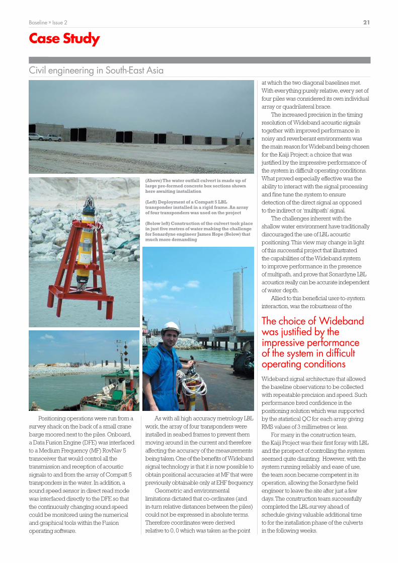
(Above) The water outfall culvert is made up oflarge pre-formed concrete box sections shownhere awaiting installation
(Left) Deployment of a Compatt 5 LBLtransponder installed in a rigid frame.An arrayof four transponders was used on the project
(Below left) Construction of the culvert took placein just five metres of water making the challengefor Sonardyne engineer James Hope (Below) thatmuch more demanding

cc
Building for successUnprecedented demand combined with almostimpossible delivery deadlines; two issues anyoneinvolved in the oil and gas industry will be all too familiarwith. Baseline visits Ocean House, Sonardyne’smanufacturing headquarters 40 miles south-west ofLondon to find out how Operations Director Tim Mooreand his team are rising to these challenges.
22 Baseline » Issue 2
OurPeople
Production – From manufacture to delivery
cc

For Operations Director Tim Moore (left) andManufacturing Manager Keith Boghurst (far left),balancing the demand from the market withproduction output is a complex challenge.Effectiveplanning, investment in the right resources andabove all team work, is the key to their success
Baseline » Issue 2 23
24 Baseline » Issue 2
OurPeople
Production – From manufacture to delivery
cc
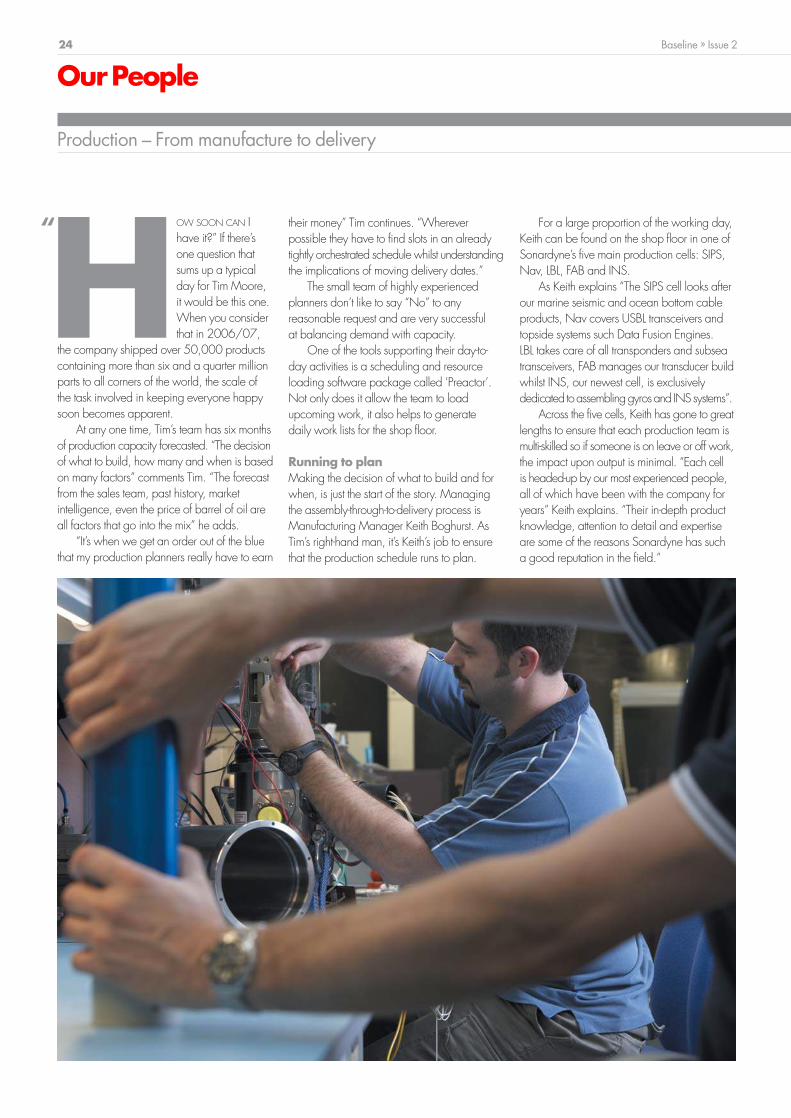
For a large proportion of the working day,Keith can be found on the shop floor in one ofSonardyne’s five main production cells: SIPS,Nav, LBL, FAB and INS.
As Keith explains “The SIPS cell looks afterour marine seismic and ocean bottom cableproducts, Nav covers USBL transceivers andtopside systems such Data Fusion Engines.LBL takes care of all transponders and subseatransceivers, FAB manages our transducer buildwhilst INS, our newest cell, is exclusivelydedicated toassemblinggyrosand INS systems”.
Across the five cells, Keith has gone to greatlengths to ensure that each production team ismulti-skilled so if someone is on leave or off work,the impact upon output is minimal. “Each cellis headed-up by our most experienced people,all of which have been with the company foryears” Keith explains. “Their in-depth productknowledge, attention to detail and expertiseare some of the reasons Sonardyne has sucha good reputation in the field.”
HOW SOON CAN Ihave it?” If there’sone question thatsums up a typicalday for Tim Moore,it would be this one.When you considerthat in 2006/07,
the company shipped over 50,000 productscontaining more than six and a quarter millionparts to all corners of the world, the scale ofthe task involved in keeping everyone happysoon becomes apparent.
At any one time, Tim’s team has six monthsof production capacity forecasted. “The decisionof what to build, how many and when is basedon many factors” comments Tim. “The forecastfrom the sales team, past history, marketintelligence, even the price of barrel of oil areall factors that go into the mix” he adds.
“It’s when we get an order out of the bluethat my production planners really have to earn
their money” Tim continues. “Whereverpossible they have to find slots in an alreadytightly orchestrated schedule whilst understandingthe implications of moving delivery dates.”
The small team of highly experiencedplanners don’t like to say “No” to anyreasonable request and are very successfulat balancing demand with capacity.
One of the tools supporting their day-to-day activities is a scheduling and resourceloading software package called ‘Preactor’.Not only does it allow the team to loadupcoming work, it also helps to generatedaily work lists for the shop floor.
Running to planMaking the decision of what to build and forwhen, is just the start of the story. Managingthe assembly-through-to-delivery process isManufacturing Manager Keith Boghurst. AsTim’s right-hand man, it’s Keith’s job to ensurethat the production schedule runs to plan.
“

Baseline » Issue 2 25
Training and recruitment With such a heavy reliance on skilled people,Tim and Keith face the perennial issue ofrecruitment. Although this is an industry wide
problem at the moment, the geographiclocation of Sonardyne’s factory makes findingthe right calibre of people as much of achallenge as building the equipment in thefirst place.
“Where we are in the south-east is knownas the Silicon Valley of the UK; an area betweenthe M3 and M4 motorways into London”says Tim. “All around us we have large blue-chip electronics manufactures such as Nokia,Motorola and Sun Microsystems competing for
the same, experienced people we are after.”One initiative aimed at addressing this
issue is Sonardyne’s apprenticeship schemethat was established five years ago. Its long
term aim is to equip people with the skill setthe company requires. “The scheme hasproved very successful and a great returnon investment. The former apprentices are allnow full-time employees making a significantcontribution to the company” remarks Keith.
As well as having the right humanresources, Sonardyne strives to ensure thatthe right physical resources are also available.Sonardyne’s factory was purpose built withthis in mind and boasts four large acoustic test
tanks, pressure vessel for depth testing,environmental chambers and dedicatedtransducer assembly lab.
New facility“When we need additional tools, whetherit’s just a new bench instrument or a completeadditional test tank, as we’ve just had installed(see Baseline Issue 1), there’s a willingness tomake that investment” said Tim.
For the last couple of years, Sonardyne’smanagement team had recognised the needfor additional production space above andbeyond what was available at Ocean House.With this in mind, when the large factoryopposite Ocean House recently came on themarket, it was the perfect opportunity for thecompany to dramatically increase capacity.
“As the ink dries on the contract, we’vegot a bit of work to do before it’s operational.The new facility presents us with many differentpossibilities, but above all, it will allow us togrow over the coming years” Timenthusiastically adds.
Testing, testingOne process that should not to beunderestimated is the huge amount of effortthat goes into testing and quality checkingevery product before it leaves the building.For example, every subsea instrument goesthrough a rigorous in-water test and calibrationthat checks its performance and functionalitybefore it’s boxed up.
The company has put much effort intogaining and maintaining its ISO 9001:2000certification which offers customers assuranceof Sonardyne’s quality control procedures.Tim explains: “My team of inspectors are avital link in the chain. We are always going toget last minute panics on a Friday afternoon;it’s the nature of the offshore industry. However,this doesn’t mean corners are cut. If we haveto make a courier wait whilst we do the finalquality checks, that’s the way it has to be”.
Tim and Keith pride themselves in meetingcustomers’ demands by setting their highlymotivated and dedicated teams tough butachievable goals. They are clearly successful;in 2006/07 they broke all company recordsfor the amount of equipment they built. Withno let up in demand, their records look setto be broken again sometime soon. BL
(Far left) Transponder assembly in one ofSonardyne’s five production cells, (Left top) qualitycontrol is integral to every step of themanufacturing process, (Left middle) everyproduct is rigorously tested in-water before beingdespatched, (Left bottom) Sonardyne’s head-quarters and to its right, the recently acquiredsecond manufacturing facility, (Above) last year6.25 million individual parts were issued toproduction, (Below) over 50,000 products are nowdespatched each year
When we need additional tools, whether it’s just anew bench instrument or a complete additional testtank, as we’ve just had installed, there’s a willingnessto make that investment”
“

Gulf of Mexico – Upgrading the Thialf
cc
26 Baseline » Issue 2
Case Study
Sonardyne engineer Julian Rickards completes the removal of the Thialf’s HiPAP® transducer. The Sonardyne Big Head (right) awaits installation
OVER THE LAST two years,
operators have become
increasingly aware of
the importance of
mitigating acoustic
interference between
construction and drilling vessels.
The risk of down time and associated
loss of revenue caused by simultaneous
multiple vessel operations (SIMOPS) is very
real, unless proper planning and selection
of the most suitable acoustic solution is
made in advance.
Responding to this situation, Heerema
Marine Contractors recently chose to install
Sonardyne Wideband acoustic technology
aboard Thialf, the World’s largest deepwater
crane vessel, which is currently at work in
the Gulf of Mexico; an area well known for
acoustic congestion.
Thialf is a 201 metre long semi-
submersible construction vessel equipped
with two cranes capable of a tandem lift of
14,200 tonnes.The vessel is equipped with
Class III Dynamic Positioning with
propulsion coming from six 5,500 kW
retractable azimuth thrusters.
The Thialf’s unique capabilities are
currently being used for SIMOPS in fields
where the number of acoustic systems in use,
leave little or no bandwidth available for the
vessel’s existing HiPAP® systems to operate.
The Sonardyne Wideband solution
supplied to Thialf involved the replacement
of the existing HiPAP® equipment with a
Dual Redundant Wideband L/USBL (Long
and Ultra-Short BaseLine) system utilising
two ‘Big Head’ transceivers.Wideband
L/USBL offers truly independent multi
operational capability through the availability
of hundreds of operating channels.The
technology also provides a highly repeatable
Wideband for the World’slargest crane vessel

Baseline » Issue 2 27
(Above) Thialf is the world’s largest crane vessel capable of lifting over 14,000 tonnes(Below) Compatt 5 transponders provide high accuracy subsea positioning of a pile
position reference for the DP system with
cross linked redundancy between
processors and transceivers.
The Big Head transceiver was chosen
because it has been specially developed to
reject thruster and other vessel generated
noise from the side and from above. It is
optimised to receive signals within a ±50°
cone which results in an improved signal-to-
noise ratio enabling the system to provide
accurate positioning on the noisiest of
vessels and in the deepest water.
A Ranger-Pro USBL topside was also
installed for survey operations and will utilise
one of the Big Head transceivers. Ranger-
Pro is notable for the ease with which it can
be used and the speed with which new
operators can become confident in working
with it.The system can work with a single
reference transponder at an operating range
of up to 7,000 metres but also has the ability
to track up to ten mobile targets.
A particular feature of Ranger-Pro is the
fast simultaneous tracking of transponders
using ‘common interrogation channels’.
For example, ten Sonardyne Wideband
Sub-Mini transponders (WSMs) can all be
updated in less than two seconds in 1,000
metres of water.The method is significantly
faster than sequential modes of interrogation
that traditionally could take up to 15 seconds
or more for the same number of targets.
For vessels with two cranes, such as the
Thialf, simultaneous updates of transponder
positions whilst lowering structures provides
much better depth feedback and hence
installation control.
Heerema Marine Contractors also
purchased a Fusion LBL software licence.
This is capable of running on the Ranger-
Pro hardware and demonstrates the
flexibility and cost-effectiveness of
Sonardyne’sWideband system architecture.
Fusion LBL is available to position multiple
subsea targets and structures on the seabed
within an array of Compatt 5 transponders
to achieve the highest attainable levels of
accuracy independent of water depth.
Typical operations might involve positioning
anchor piles, manifolds or templates and
multiple ROVs working in close proximity
to each other as well as streaming sensor
data from gyros, precision digiquartz
pressure sensors, inclinometers and the like.
The installation aboard the Thialf offers
a truly comprehensive and advanced
positioning capability.

cc
28 Baseline » Issue 2
Technology
Systems and Products
SIPS 2 Inline TransceiverBuilt to withstand wrapping onto streamer cable drums, the Inline XSRS transceiverallows operators to dramtically improve the efficiency of their back-deck operations
The Inline XSRS transceiver is the latest
addition to Sonardyne’s SIPS 2 streamer
positioning product range.
SIPS 2 (Seismic Integrated Positioning
System) uses a network of acoustic
transceivers attached to each streamer,
air gun and tailbuoy/ navbuoy to measure
ranges between each other and the survey
vessel.This enables both the shape of the
towed array to be known and the positions
of the hydrophones, relative to the survey,
to be precisely determined.
Offering the same performance advantages
as existing ‘clip-on’ XSRS transceivers, the
new Type 8085 unit is designed to fit in-
between streamer sections thus allowing
streamers to be deployed and recovered
without having to attach or remove any
acoustic hardware.This allows for faster
and more efficient survey operations whilst
improving back-deck health and safety.
Like all SIPS 2 XSRS’, the Inline XSRS uses
Digital Signal Processing with multiple
modulation modes to suit different operating
conditions.The rugged intelligent transducer
array reduces surface and bottom bounce
effects using beam steering technology.
Communications and power are picked up
from the streamer, whilst all other lines are
passed through the unit in a shielded cable
bundle. By eliminating the need for an
internal battery pack the safety risks and
downtime in replacing batteries, whilst
streamers are deployed, is removed.
The unit is manufactured from Titanium which
offers both exceptional corrosion resistance
and high strength.
Manufactured from Grade 5 Titanium,the Inline XSRS is designed to withstandhigh operational loads and wrapping ontodrums.It has a working load of 30kN anduses industry standard 37 pin Syntrakconnectors to connect into the streamer
SIPS 2 Inline TransceiverFacts & Figures
● Fully compatible with existing
‘clip-on’SIPS 2 XSRS units allowing
users to mix and match hardware
● Requires no new software or
operator training
● No need to remove during streamer
deployment and recovery
● No limitations on transceiver
position due to coil locations
● External and internal seals to
prevent canister flooding
● Designed to integrate with TSS
and Syntrak streamers
● Less unit losses due to in-water
debris

Baseline » Issue 2 29
Technology
Systems and Products
Deck Test UnitAn easy-to-use splash-proof transponder unit for testing Compatt 5, DTU and WSMtransponders in the workshop or the harsh environment of the back-deck
The DTU is powered by Lithium-ionbatteries providing up to 8 hours ofcontinuous testing.The unit can also bemains powered and is environmentallyprotected to IP65 making it suitable foruse in most operating conditions
The Type 8063 Deck Test Unit (DTU) has
been developed as a fully portable, splash-
proof transponder test unit.The DTU now
supercedes Sonardyne’s popular ANT
product as the primary test equipment for
Sonardyne and other acoustic instruments,
whether in the workshop or on the back-deck.
The DTU is capable of transmitting and
receiving both Sonardyne Wideband™
and tone acoustic signals in order to test
and set-up the functionality of all MF
frequency Compatt 5s, DPTs and WSM
transponders. Ranging, acoustic command
function and the release mechanism can all
be tested prior to deployment, using the
test transducer.
The unit offers the potential for significant
time and cost savings with a range of
practical features based on Sonardyne’s
long experience of supplying technology to
the offshore and oceanographic industries.
For example, if a serial connection is made
to the Compatt 5 or DPT, the DTU will extract
all the transponder settings needed to be
able to test the unit, simplifying the testing
operation.The results of tests performed
by the device are stored internally in a test
record that can be uploaded via a USB port
to a PC for long-term storage whilst the
large LCD display is designed for both
sunlight reading and low-light conditions.
Although initially programmed to perform
acoustic and cable-connected tests on
Compatt 5s, DPTs and WSMs, the DTU’s
firmware can be easily upgraded by the
user so that the unit can be used for testing
other acoustic positioning instruments and
their functionality.
Deck Test UnitFacts & Figures
● Test transponders acoustically
including Wideband ranging
● WSM Responder test capability
● Supplied in a portable,rugged and
splash-proof case
● Continuous battery life of 8 hours
with Lithium-ion battery
● Universal mains-powered charger
● Display suitable for bright sunlight
and low-light conditions
● Electronic manuals available via
USB connection to PC
● Firmware upgrades to test other
instruments

cc
30 Baseline » Issue 2
International
News from around the World
SE Asia – SingaporeJohn RamsdenVP Asia
USA – HoustonSpencer CollinsVP Americas
UK – AberdeenDerek DonaldsonVP Europe and Africa
Brasil – MacaéGavin HuntingRegional Manager
Although it’s been hectic since
I rejoined Sonardyne, its great
to be back. One of my first tasks
was to strengthen the team up
here in Aberdeen.With this in
mind Barry Cairns who was
based in Blackbushe has re-
located to Aberdeen and brings
with him a wealth of technical
knowledge.
World’s largest
In March, the world’s largest
pipelay vessel Allseas’ ‘Solitaire’
upgraded its acoustic positioning
system to the latest wideband
solution. Installation was
completed in just one and a
half days.
Following this record breaker,
we’ve just upgraded Heerema’s
‘Thialf’, the world’s largest
crane vessel for work in the
acoustically crowded Gulf of
Mexico (Page 26).These two
vessls add tremendous prestige
to our track record.
Allseas fleet
Allseas have continued with
their investment in Wideband
technology. A complete LBL
and USBL spread of equipment,
together with two Lodestars, will
provide field wide positioning
for the Allseas fleet mobilised
on the KG-D6 project for
Reliance offshore India.
Sonardyne Asia have been
very busy over the last quarter
not only in terms of sales and
support but also with training,
product releases and a regional
agents meeting.
Training
Product training has been
conducted in the Singapore
office utilising the virtual acoustic
link with the main training centre
in Plymouth, UK.This link allows
an office based training scenario
in Singapore to use real acoustics
at the UK training centre by way
of an internet link which has
proven both successful and
popular.
Agents seminar
All the Sonardyne agents from
around Asia came into Singapore
for a seminar covering all the
existing product lines and
also the latest releases of
equipment including Lodestar
and Sentinel.
Stop Press:Tsunami update
As Baseline goes to press, we’ve
just heard that our newly
installed tsunami system (Page
06) successfully detected a
tsunami wave created by an
earthquake registering 6.2 on
the Richter Scale in the Bay of
Bengal shortly before midnight
on 25th July.
The expansion of activity
continues for us here at
Sonardyne Brasil.This period is
proving very busy for installation
and commissioning of new
systems as well as upgrading
of existing ones.
The construction survey market
is going through a period of
significant growth.This is
reflected by the number of RSVs
currently been mobilised and
also recently awarded contracts.
We have now nearly completed
the installation phase of the RSV
CBO Rio which will be working
for Petrobras.This is fitted with
Fusion USBL, LBL and a
hydraulic deployment machine.
Commissioning of the system
has already begun.
Coming up soon we will
commence mobilisation on the
second RSV, also from CBO,
which will have a very similar
scope of supply.
Drilling market
On the drilling side of things
we will be upgrading systems
on the Ocean Alliance, Seillean
FPSO and also installing and
commissioning of a new
Wideband Ranger MRAMS
system on the recently arrived
Ocean Whittington.
The first half of the year has
been exciting and dynamic.
New recruits have included Dan
Zatezalo joining our field support
team, Nicki Howard in admini-
stration and Brandon Bowie into
sales, following an honorable
discharge from the US Navy.
SIMOPS
A key activity for Sonardyne Inc.
has been the support of the Oil
Majors including Chevron and
Shell to provide solutions to
manage interference problems
caused by SIMOPS with Narrow
Band positioning systems in the
Tahiti, Deimos and Mars fields.
Through proactive involvement
and management by the Major’s
the optimal solution to install
Sonardyne Wideband systems
on a number of vessels was
implemented. Installations
included Heerema’s Thialf,
Highland Fortress,Transocean’s
Cajun Express and Transocean’s
Discoverer Spirit.
Deep water USBL
Activity has also been strong
across all of our product range
in deep water applications.With
demand particularly strong for
permanent vessel based USBL
systems as owners shift focus
from dedicated PSV’s or AHTS
to multi-role capability.

Ask Dave
cc
Baseline » Issue 2 31
Help & Advice
Your questions answered
If there’s something you’ve always been
meaning to ask us,then I’m here to get
you the answer.Whether its a technical
query or a handy hint,email me your
questions at [email protected].
Some of the best questions will appear
in the next issue of Baseline.
QI am currently planning a
Wideband LBL job in an area
where there is significant
variation of sound speed.
How could this affect the
system performance? What can l do to
optimise the system for this environment?
AAn error in sound speed
causes a systematic error
which will scale the signal
travel time and thus the
computed range to the detriment of
calibration and tracking quality.
To visualise the effect, think of a
histogram displaying the measured
ranges against frequency of occurrence.
Ideally the dataset should be free from
systematic error and subject only
to random error.This will give a ‘short
and tall’normal distribution trend line.
If sound speed is not accounted for
sufficiently, the histogram will reflect
this with a larger measurement spread.
Sometimes this can be seen as two distinct
groupings of reciprocal measurements
if the sound speed changed during
baseline calibration.
The significance of this error has
been exacerbated due to the repeatable
centimetric precision achievable over
greater distances using Wideband LBL
than was previously possible with tone
systems. Indeed,the greater the distance
the greater the significance of sound
speed error.To achieve the quoted
0.03m overall accuracy of Wideband LBL,
I recommend regularly monitoring sound
speeds across each baseline using
Compatt 5’s with sound speed sensors
which offer an accuracy of +/- 0.06m/s.
QHi Dave,I have a ROV-Homer
transceiver that I need to set-
up to receive signals from a
37kHz emergency pinger.
How do I go about it?
AThis is a straightforward one.
Using the PC software supplied
with the ROV-Homer simply
select AODC Channel A or
Channel B from the list of transponders
available.The ROV-Homer will then be
able to pick up the signals from the
pinger. Remember,in this case the ROV-
Homer will only give you a direction to
the pinger as you are not actually
interrogating it to calculate range.
QWe have received updates
for our Fusion and Ranger
software.
I want to prepare some
notes for our users on how to
interface Ranger to our navigation
software.To do this I would like to run the
software in simulate mode and acquire
some screen grabs of the report
configuration for a Kongsberg SSB output.
I can get the software into simulate
mode,with a vessel position and a
transponder however I get a message
zero transponders can be tracked at a
time when I try to enable the output.
We have a Fusion Office dongle.
Should the Ranger software recognise this
or is a separate dongle needed?
AYou will need to send in
an email to our Customer
Support Team to get your
dongle updated as a Fusion
Office dongle is not recognised by Ranger.
They can do this update remotely, just
follow the instructions that you receive.
QWe are using a Fusion USBL
system with a Wideband MF
RovNav 5 on one of our ROVs
but we are having some
problems when we try to use
it as a USBL responder. It appears to be
set up correctly for responder mode but
when the vehicle that we have the
instrument attached to is put online it
will not track and comes up with an error
message saying that it is unable to track.
Could you please have a look at our
job set-up and see if we have a problem?
ATo operate the RovNav 5 as
a responder you must first
ensure you are running Fusion
USBL Survey software and not
just the standard Fusion USBL software.If
you are not, go to Start Menu\ Programs\
Sonardyne\ Pharos. Survey will be one
of the icons listed.
Once this is done,unplug the RovNav
5 from the responder card in the back of
your NCU.You will then need to plug it
into the transceiver card. However,as
your USBL transceiver is currently using
this card,you will need to fit a second
transceiver card.This will allow you to
use the USBL transceiver whilst operating
the RovNav in responder mode.
I would advise you to create a new job
to start this set-up to prevent making lots
of changes to an existing job which could
cause conflicts.
With over 20 years experience here at Sonardyne, Dave Mould has all the answers

cc
www.sonardyne.com
Trusted Solutions.
Copyr
ight
Sona
rdyn
e In
tern
atio
nal Li
mite
d.
Spec
ifica
tions
sub
ject
to c
hang
e w
ithout
notic
e. P
rint
ed 0
9/07


![[Arup] Have You Wondered What GDP Means](https://img.dokumen.tips/doc/110x75/55cf8631550346484b952b52/arup-have-you-wondered-what-gdp-means.jpg)