Embed Size (px)
Citation preview

FF FEE E
AA ASS S
II I BB BII I LL L
II I TT TYY Y
RR R
EE EPP P
OO ORR R
TT T
PPN Power Generating Company Pvt. Ltd
Pillaiperumalnallur & Manikkapangu village, Nagapatinam District,Tamil Nadu
2 x 160 MW Coal based Thermal Power Plant
September 2014
FICHTNER Consulting Engineers (India) Pvt. Ltd. Chennai, India
Doc. Number : 1114121-ME-FSR-700-002, Rev. A

PPN POWER GENERATING COMPANY PVT. LTD
2 x 160 MW Coal based Thermal Power Plant
Feasibility Report
Doc.No. 1114121-ME-FSR-700-002, Rev.A FICHTNER INDIA
Page 2 of 66 feasibility_report_2x160 mw tpp ppn-rev a.docx
Table of Contents
1.0 Project Highlights ....................................................................................................... 8
2.0 Executive Summary .................................................................................................. 12
2.1 Introduction .................................................................................................................... 12
2.2 Project Description ......................................................................................................... 12
2.3 Site Analysis ................................................................................................................... 12
2.4 Planning Brief ................................................................................................................. 13
2.5 Proposed Infrastructure .................................................................................................. 13
2.6 Rehabilitation and Resettlement (R&R Plan) ................................................................. 13
2.7 Project schedule and Cost Estimates ............................................................................ 13
2.8 Analysis of the Proposal ................................................................................................. 14
3.0 Introduction of the project ....................................................................................... 15
3.1 About the project proponent ........................................................................................... 15
3.2 Brief description of the Project ....................................................................................... 15
3.3 Demand and Supply Gap ............................................................................................... 15
3.4 Necessity and Justification of the Project ...................................................................... 18
4.0 Project Description ................................................................................................... 20
4.1 Proposed Site Location .................................................................................................. 20
4.2 Salient Technical Features ............................................................................................. 21
4.3 Generator ....................................................................................................................... 35
4.4 Water System ................................................................................................................. 35
4.5 Raw Material .................................................................................................................. 37
4.6 Electrical System ............................................................................................................ 42
4.7 Control and Instrumentation System .............................................................................. 43
5.0 Environmental and Pollution Aspects .................................................................... 44
5.1 Air Pollution .................................................................................................................... 44
5.2 Ash Disposal and Utilization........................................................................................... 46
5.3 Green Belt ...................................................................................................................... 46
5.4 Rain Water Harvesting ................................................................................................... 47
5.5 Ground Water ................................................................................................................. 47
6.0 Site Analysis .............................................................................................................. 48
6.1 Connectivity .................................................................................................................... 48

PPN POWER GENERATING COMPANY PVT. LTD
2 x 160 MW Coal based Thermal Power Plant
Feasibility Report
Doc.No. 1114121-ME-FSR-700-002, Rev.A FICHTNER INDIA
Page 3 of 66 feasibility_report_2x160 mw tpp ppn-rev a.docx
6.2 Current Usage& Land Classification .............................................................................. 48
6.3 Topography .................................................................................................................... 48
6.4 Tidal levels ..................................................................................................................... 49
6.5 Seismic Zone ................................................................................................................. 49
6.6 Soil classification ............................................................................................................ 49
6.7 Climate ........................................................................................................................... 50
6.8 Existing infrastructure ..................................................................................................... 50
7.0 Planning Brief ............................................................................................................ 51
7.1 Planning Concept ........................................................................................................... 51
7.2 Land use planning .......................................................................................................... 52
7.3 Population Projection ..................................................................................................... 53
8.0 Proposed Infrastructure ........................................................................................... 54
8.1 Industrial Area ................................................................................................................ 54
8.2 Residential Area ............................................................................................................. 54
8.3 Green Belt ...................................................................................................................... 54
8.4 Connectivity .................................................................................................................... 54
8.5 Drinking Water Management ......................................................................................... 54
8.6 Sewage Treatment ......................................................................................................... 54
8.7 Industrial Waste Management ....................................................................................... 54
8.8 Solid Waste Management .............................................................................................. 55
9.0 Rehabilitation and Resettlement (R&R ) Plan ........................................................ 56
9.1 Project Benefit ................................................................................................................ 56
9.2 Corporate Social Responsibility ..................................................................................... 56
10.0 Project Schedule & Cost Estimates ........................................................................ 57
10.1 Project Schedule ............................................................................................................ 57
10.2 Method of Executing the Project .................................................................................... 57
10.3 O&M Staff ....................................................................................................................... 57
10.4 Project Cost Estimates and Cost of Generation ............................................................ 57
11.0 Analysis of Proposal (Final Recommendations) ................................................... 60
Appendix - 1 Project Information ................................................................................................ 61
Appendix - 2 Typical Ultimate Coal Analysis .............................................................................. 63
Appendix - 3 Typical Fuel Oil Analysis ....................................................................................... 64
Appendix – 4 Seawater Analysis ................................................................................................. 65

PPN POWER GENERATING COMPANY PVT. LTD
2 x 160 MW Coal based Thermal Power Plant
Feasibility Report
Doc.No. 1114121-ME-FSR-700-002, Rev.A FICHTNER INDIA
Page 4 of 66 feasibility_report_2x160 mw tpp ppn-rev a.docx
List of Exhibits
Exhibit - 01 Project location map
Exhibit - 02 Plot Plan
Exhibit - 03 Heat and Mass Balance Diagram
Exhibit - 04 Water Balance Diagram
Exhibit – 05A Truck Catalogue
Exhibit – 05B Proposed Railway Line near the Plant
Exhibit - 06 HTL and LTL Demarcation Map
Exhibit - 07 Existing seawater intake and outfall facilities

PPN POWER GENERATING COMPANY PVT. LTD
2 x 160 MW Coal based Thermal Power Plant
Feasibility Report
Doc.No. 1114121-ME-FSR-700-002, Rev.A FICHTNER INDIA
Page 5 of 66 feasibility_report_2x160 mw tpp ppn-rev a.docx
Glossary
AAI Airport Authority of India
AAQ Ambient Air Quality
ACW Auxiliary Cooling Water
AHU Air Handling Unit
BFP Boiler Feed Pump
BOP Balance of Plant
CAC Care Air Center
CEA Central Electricity Authority
CEP Condensate Extraction Pump
CERC Central Electricity Regulatory Commission
CFBC Circular Fluidized Bed Combustion Boiler
COC Cycle of Concentration
CPCB Central Pollution Control Board
CT Cooling Tower
C&I Control & Instrumentation
CW Circulating Water
DM De-mineralized
DSCR Debt Service Coverage Ratio
ECR East Coast Road
EIA Environment Impact Assessment
EPC Engineering, Procurement & Construction
EPS Electric Power Supply
ESP Electro Static Precipitator
ETP Effluent Treatment Plant
FBC Fluididzed Bed Combustion
FBHE Fluidized Bed Heat Exchanger
FGD Flue Gas Desulphurizstion
GCV Gross Calorific Value
GOI Government of India
GTG Gas Turbine Generator
HFO Heavy Fuel Oil/Heavy Furnace Oil
HP High Pressure
IBR Indian Boiler Regulations
IDC Interest During Construction
IDCT Induced Draft Cooling Tower

PPN POWER GENERATING COMPANY PVT. LTD
2 x 160 MW Coal based Thermal Power Plant
Feasibility Report
Doc.No. 1114121-ME-FSR-700-002, Rev.A FICHTNER INDIA
Page 6 of 66 feasibility_report_2x160 mw tpp ppn-rev a.docx
INR Indian Rupee
IRR Internal Rate of Return
ISPS International Ship and Port Facility Security
LDO Light Diesel Oil
LP Low Pressure
LFP Land Fall Point
MCR Maximum Continuous Rating
MGF Multi Grade Filter
MH Manhole
MKWH Million Kilo Watt hr.
MLD Million Liters Per Day
MOEF Ministry of Environment and Forest
MSL Mean Sea Level
MU Million Units
NH National Highway
Nm3 Normal Meter Cube
NOC No Objection Certificate
NOx Nitrogen Oxide
NSPC Navigational Safety Ports Committee
NTP Notice To Proceed
O&M Operation & Maintenance
PF Power Factor
PFF Pulverized Fuel Fired
PHE Plate Heat Exchanger
PLF Plant Load Factor
PPN PPN Power Generating Company Private Limited
PRDS Pressure Reducing and Desuperheating Station
RH Relative Humidity
ROE Return on Equity
ROW Right of Way
R&R Rehabilitation & Resettlement
SERC State Electricity Regulatory Commission
SOx Sulphurdioxide
SPCB State Pollution Control Board
SPM Suspended Particulate Matter
STG Steam Turbine Generator
STP Sewage Treatment Plant

PPN POWER GENERATING COMPANY PVT. LTD
2 x 160 MW Coal based Thermal Power Plant
Feasibility Report
Doc.No. 1114121-ME-FSR-700-002, Rev.A FICHTNER INDIA
Page 7 of 66 feasibility_report_2x160 mw tpp ppn-rev a.docx
TAC Tariff Advisory Committee
TANGEDCO Tamil Nadu Generation and Distribution Corporation
TG Turbine Generator
TNEB Tamil Nadu Electricity Board
TNPCB Tamil Nadu Pollution Control Board,
TOR Terms of Reference
TPD Tones Per Day
TPS Thermal Power Station
TWAD Tamil Nadu Water Supply and Drainage Board
WC Working Capital
PPN POWER GENERATING COMPANY PVT. LTD
2 x 160 MW Coal based Thermal Power Plant
Feasibility Report
Doc.No. 1114121-ME-FSR-700-002, Rev.A FICHTNER INDIA
Page 8 of 66 feasibility_report_2x160 mw tpp ppn-rev a.docx
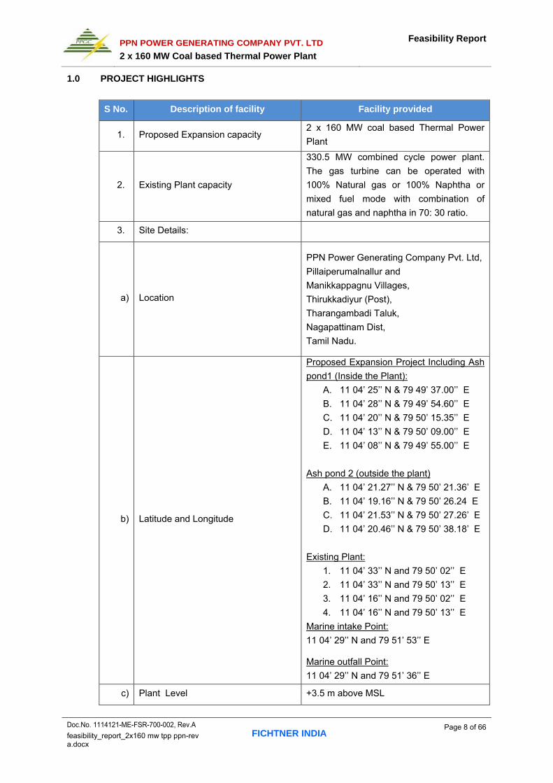
1.0 PROJECT HIGHLIGHTS
S No. Description of facility Facility provided
1. Proposed Expansion capacity 2 x 160 MW coal based Thermal Power
Plant
2. Existing Plant capacity
330.5 MW combined cycle power plant.
The gas turbine can be operated with
100% Natural gas or 100% Naphtha or
mixed fuel mode with combination of
natural gas and naphtha in 70: 30 ratio.
3. Site Details:
a) Location
PPN Power Generating Company Pvt. Ltd,
Pillaiperumalnallur and
Manikkappagnu Villages,
Thirukkadiyur (Post),
Tharangambadi Taluk,
Nagapattinam Dist,
Tamil Nadu.
b) Latitude and Longitude
Proposed Expansion Project Including Ash
pond1 (Inside the Plant):
A. 11 04’ 25’’ N & 79 49’ 37.00’’ E
B. 11 04’ 28’’ N & 79 49’ 54.60’’ E
C. 11 04’ 20’’ N & 79 50’ 15.35’’ E
D. 11 04’ 13’’ N & 79 50’ 09.00’’ E
E. 11 04’ 08’’ N & 79 49’ 55.00’’ E
Ash pond 2 (outside the plant)
A. 11 04’ 21.27’’ N & 79 50’ 21.36’ E
B. 11 04’ 19.16’’ N & 79 50’ 26.24 E
C. 11 04’ 21.53’’ N & 79 50’ 27.26’ E
D. 11 04’ 20.46’’ N & 79 50’ 38.18’ E
Existing Plant:
1. 11 04’ 33’’ N and 79 50’ 02’’ E
2. 11 04’ 33’’ N and 79 50’ 13’’ E
3. 11 04’ 16’’ N and 79 50’ 02’’ E
4. 11 04’ 16’’ N and 79 50’ 13’’ E
Marine intake Point:
11 04’ 29’’ N and 79 51’ 53’’ E Marine outfall Point:
11 04’ 29’’ N and 79 51’ 36’’ E
c) Plant Level +3.5 m above MSL

PPN POWER GENERATING COMPANY PVT. LTD
2 x 160 MW Coal based Thermal Power Plant
Feasibility Report
Doc.No. 1114121-ME-FSR-700-002, Rev.A FICHTNER INDIA
Page 9 of 66 feasibility_report_2x160 mw tpp ppn-rev a.docx
S No. Description of facility Facility provided
d) Approach
A separate right of way to be established
up to ECR/NH 45A which is 2.5 Km away
from expansion project plant boundary.
e) Nearest town
Talulk:
Taragambadi (5.9 km , SSE) Town :
Karaikal (20 km, S)
Nagapatitinam (35 km, S)
District headquarters:
Nagapattinam (35 km, S)
f) Nearest Railway Station Mayiladuthurai which is at distance of
22 km, NW
g) Nearest Sea / Port Karaikal port (35 km, S)
h) Nearest airports Tiruchirappalli (150 km, SW)
4. Land Availability and requirement
Total project Area : 436.7 Acres
Area required for expansion
project : 100 Acres
Land is already in possession as the
project is expansion of the existing power
plant area.
Additional land for right of way outside the
present project site to link the ECR/NH
45A Road needs to be procured/leased
and the same is being undertaken.
5. Water system
a) Source
The plant site is located approximately 2.5
km from Bay of Bengal. To meet both
consumptive and condenser cooling water
requirements, seawater is being used.
The Existing plant seawater intake and
discharge structure will be used for
expansion project.
b) Intake and Outfall Requirement
a. Sea water intake requirement will be
4403 m³/hr
b. Sea water to outfall will be
3536 m³/hr
c) Cooling System Closed cycle cooling system with

PPN POWER GENERATING COMPANY PVT. LTD
2 x 160 MW Coal based Thermal Power Plant
Feasibility Report
Doc.No. 1114121-ME-FSR-700-002, Rev.A FICHTNER INDIA
Page 10 of 66 feasibility_report_2x160 mw tpp ppn-rev a.docx
S No. Description of facility Facility provided
mechanical draft cooling towers
6. Fuel source Imported coal from Indonesia and other
possible sources.
a) Coal Requirement 3900 TPD / 1.2 MTPA for Imported coal of
both units
b) Coal Transportation By ship up to Karaikal Port and by NH 45A
ECR road up to project Site.
c) HFO/LDO Requirement 1200 KL/ annum
d) HFO/LDO Transportation By Road
Fuel storage at Site:
a) Coal 30,000 T for each unit
b) HFO/LDO 2 nos of Tank each 500 m3
7. Ash collection & disposal system
a) Collection At bottom Ash hopper, Eco hoppers, APH
hoppers and ESP hoppers
b) Total Ash Generation 468 TPD / 0.144 MTPA
c) Disposal
a) Ash collected in ESP & APH hoppers in
dry form.
b) Ash collected in Bottom Ash (including
Eco hoppers) will be in wet form
d) Priorities of disposal
1. Normal Ash disposal will be in dry
form to users.
2. Emergency Ash disposal and during
commissioning of the plant as well as
first year of operation will be in wet
form to the ash dyke.
8. Steam Generator Pulverized Fuel (PF) Boiler
9. Steam Turbine Generator
Steam turbine would be 3000 rpm, tandem
compound, single reheat, regenerative
cycle configuration with six uncontrolled
extractions for regenerative feed heating.
Generator will be directly driven by steam
turbine at 3000 rpm. The Generator and its
excitation system will have a capability at
least matching the declared maximum
continuous rated output of the associated
steam turbine.
10. Control System Distributed Digital Control and

PPN POWER GENERATING COMPANY PVT. LTD
2 x 160 MW Coal based Thermal Power Plant
Feasibility Report
Doc.No. 1114121-ME-FSR-700-002, Rev.A FICHTNER INDIA
Page 11 of 66 feasibility_report_2x160 mw tpp ppn-rev a.docx
S No. Description of facility Facility provided
Management Information System
(DDCMIS) with integrated, CRT/Key Board
operation for Steam Generator, Turbine,
Generator and auxiliaries from Central
Control room.
11. Plant Operation Philosophy Base Load
12. Chimney 1 no. of twin flue 220 m tall chimney
13. Project completion schedule First unit - 28 Months from NTP
Second unit - 32 Months from NTP
14. Manpower 145 persons. (during O&M) and about
1000 persons at the peak of construction.
15. Annual PLF 85%
16. Annual gross generation at 85% PLF 2382.72 million units
17. Auxiliary power consumption 10 %
18. Annual Net generation 2144.45 million units
19. Fuel Cost of coal at Site Rs. 5000 per tonne
20. Estimated Project cost
a) Without IDC & Financial Charges Rs. 14081.64 Million
b) With IDC & Financial Charges Rs.16493.10 Million
21. Specific cost per MW installed With
IDC Rs.5.154 Cr/MW
22. Levelised tariff (Over 25 years) Rs.5.41/ KWh
PPN POWER GENERATING COMPANY PVT. LTD
2 x 160 MW Coal based Thermal Power Plant
Feasibility Report
Doc.No. 1114121-ME-FSR-700-002, Rev.A FICHTNER INDIA
Page 12 of 66 feasibility_report_2x160 mw tpp ppn-rev a.docx
2.0 EXECUTIVE SUMMARY
2.1 Introduction
PPN Power Generating Company Pvt. Ltd. (PPN) having its corporate office at Chennai,
owns and operates a Combined Cycle Power Station of 330.5 MW capacity at villages of
Pillaiperumalnallur and Manikkapangu of Tharangambadi Taluk of Nagapattinam District,
Tamil Nadu. The existing plant is designed for 100% natural gas firing or 100% naphtha firing
or a mixture of natural gas and naphtha firing ( 70 % : 30%). Presently plant is operated using
100 % naphtha due to shortage of gas from PY-01 off shore well.
Since the prospects of availability of gas is remote, PPN is now planning to expand the power
plant capacity from 330.5 MW to 490.5 MW by installing 2 x 160 MW coal based thermal
power plant in existing plant premises.
PPN has appointed Fichtner Consulting Engineers (India) Pvt. Ltd., Chennai as their
Consultant/ Engineer for the preparation of Feasibility Report of the Project.
This Feasibility report is prepared based on the MOEF guidelines dated 30th December 2010
for obtaining environmental clearance. The objective of this Feasibility Report is to establish
the technical and commercial feasibility of the project giving details such as the site features,
basic plant configuration, salient technical features and financial parameters of the proposed
2 x 160 MW Thermal Power Plant.
2.2 Project Description
The proposed power project will be located adjacent to the existing combined cycle power
plant location. The proposed site is located in Pillaiperumalnallur and Manikkapangu villages
near Thirukkadaiyur in Tharangambadi Taluka of Nagapatinam District, Tamil Nadu. The
plant will be designed for base load operation with minimum plant design life of 25 years.The
coal required for the proposed project will be sourced from Indonesia and other possible
sources. To cater both consumptive and condenser cooling water requirements, seawater will
be used. The existing plant seawater intake and discharge structure will be used for
expansion project.
2.3 Site Analysis
The project site is located in Nagapattinam District of Tamil Nadu. The neighboring state
Puducherry (Karaikal) is at an aerial distance of 8.2 km from the site boundary. The proposed
site is well connected by road. National highway NH 45A from Nagapattinam to Cuddalore is
about 2.5 km away from the proposed site. Thirukadayur town and Tharangambadi town are
2.5 km and 5.9 km from the site. Nearest Railway Station is Mayiladuthurai which is at
distance of 22 km from the site. The nearest major airport is at Trichirapalli, which is about
150 km from the site. The nearest sea port is located in Karaikal which is about 35 km from

PPN POWER GENERATING COMPANY PVT. LTD
2 x 160 MW Coal based Thermal Power Plant
Feasibility Report
Doc.No. 1114121-ME-FSR-700-002, Rev.A FICHTNER INDIA
Page 13 of 66 feasibility_report_2x160 mw tpp ppn-rev a.docx
the site. The Site elevation is about +3.5 above Mean sea levels. Topography of the proposed
site ranges from relatively flat to slightly undulating and will require nominal Cutting and filling.
About 100 acres of land is identified within the existing site boundary which is suitable for
setting up the power project.
2.4 Planning Brief
With the available land, fuel logistics and considering environmental requirements, it is
proposed to install coal fired thermal power plant of 2 X 160 MW capacity. The power
available for evacuation will be about 288 MW. The estimated auxiliary power consumption
of about 32 MW (10%). The Plant Load Factor (PLF) being considered is 85% and plant
availability upto 90% is considered. It is envisaged that the unit would be put in to commercial
operation in about 28 months from NTP for first unit and 32 months for second unit. Technical
requirements of power evacuation from the proposed power plant will be decided by the grid
authority. The power delivery point will be firmed up based on the transmission study by grid
authority. Sub critical steam generators of Pulverized fuel fired are proposed for this project.
2.5 Proposed Infrastructure
Existing total project area is 436.7 Acres which is in industrial category. The Area required for
expansion project will be about 100 Acres. Land is already in possession as the project is
expansion of the existing power plant area. The proposed 100 acres of land will include
74.25 acres of processing area (Industrial area) and 25.75 acres of green belt. To meet both
consumptive and condenser cooling water requirements, seawater will be used. The Existing
plant seawater intake facility will be used for expansion project. Waste water generated will
be collected in the outfall tank from where it will be delivered by a pump to the existing plant
seal pit which delivers the sea water back to the sea through the existing sea water outfall
system. The bottom ash and fly ash generated will be managed as per MoEF norms. While
the sewage solid wastes generated within the plant will be treated and the products will be
used horticulture purpose.
2.6 Rehabilitation and Resettlement (R&R plan)
The proposed power project will be located adjacent to the existing plant within the existing
plant site boundary. Additional land for right of way outside the present project site to connect
the ECR/NH 45A Road needs to be procured/leased and the same is being undertaken.
Necessary measures will be taken to leave away the habitation areas and the project is
planned without acquiring any residential areas. Rehabilitation & Relocation (R&R) issues
appear to be not involved. Further a detailed EIA study as per TOR of MOEF will be
conducted for establishing project specific data.
2.7 Project schedule and Cost Estimates
It is envisaged that the unit would be put in to commercial operation in about 28 months
reckoned from the zero date i.e the date of NTP for first unit and 32 months for the second

PPN POWER GENERATING COMPANY PVT. LTD
2 x 160 MW Coal based Thermal Power Plant
Feasibility Report
Doc.No. 1114121-ME-FSR-700-002, Rev.A FICHTNER INDIA
Page 14 of 66 feasibility_report_2x160 mw tpp ppn-rev a.docx
unit. The total cost of the project has been estimated at Rs. 1649.310 Crores (including IDC)
which works out to Rs 5.154 Cr/MW. The cost of generation works out to Rs. 4.94 / kWh in
the first year of operation and levelized tariff works out to Rs. 5.41 / kWh.
2.8 Analysis of the Proposal
With the projected future power demand scenario in India especially in the Southern India and
State of Tamil Nadu installing a Power Plant of 2 x 160 MW capacity, close to water source
and adequate availability of suitable land, existing infrastructures, without R&R issues etc., is
considered to be economically viable. The plant concept and the technical features of the
selected plant and equipment are standard and proven. The Thermal Power project will
contribute to the Government exchequer by way of indirect and direct taxes. The project will
also generate direct and indirect employment opportunities which will benefit the local
population. The project will require the skilled workforce which will be actively facilitated by
the Company. A large number of persons from the young population will be benefited.

PPN POWER GENERATING COMPANY PVT. LTD
2 x 160 MW Coal based Thermal Power Plant
Feasibility Report
Doc.No. 1114121-ME-FSR-700-002, Rev.A FICHTNER INDIA
Page 15 of 66 feasibility_report_2x160 mw tpp ppn-rev a.docx
3.0 INTRODUCTION OF THE PROJECT
3.1 About the project proponent
PPN Power Generating Company Pvt. Ltd. having its corporate office in Chennai owns and
operates the existing dual fuel fired Combined Cycle Power Station of 330.5 MW capacity.
The existing plant is located at Pillaiperumalnallur and Manikkapangu villages near
Thirukkadaiyur in Tharangambadi Taluka of Nagapatinam District along the south east coast
of India approximately 280 km south of Chennai and 22 km east of the town of
Mayiladuthurai.
3.2 Brief description of the Project
PPN is now in the process of setting up coal based thermal power plant. It is an expansion of
the existing power station with coal as fuel at the same location. The capacity of Unit will be
2 x 160 MW. The proposed plant will be built at the Southern segment of the PPN asset
established for the operating the existing combined cycle power plant and will be considered
as an independent entity. Earlier an environmental clearance and CRZ clearance was
provided by MOEF for the natural gas based PPN expansion power project (1080MW) for the
same location where the project is proposed.
3.3 Demand and Supply Gap
3.3.1 Power Supply and Demand Position in India
Over the years, the Electricity Industry has made significant progress. Installed capacity has
increased from 1700 MW (1950) to 2,34,602 MW (31stJanuary 2014).Annual per capita
electrical energy consumption has increased from 16 KWh/annum (1950) to over
884 kWh/annum (2013). The present average growth rate in power generation is about 6%.
Actual Power Demand Vs Supply Position in India
Year Demand (MW) Supply (MW) Deficit (%)
2002-03 81492 71547 12.2
2003-04 84574 75066 11.2
2004-05 87906 77652 11.7
2005-06 93255 81792 12.3
2006-07 100715 86818 13.8
2007-08 108866 90793 16.6
2008-09 109809 96685 11.9
2009-10 119166 104009 12.7
2010-11 122287 110256 9.84
2011-12 130,006 116191 10.6
2013-14 135918 129,815 4.5 As per CEA report

PPN POWER GENERATING COMPANY PVT. LTD
2 x 160 MW Coal based Thermal Power Plant
Feasibility Report
Doc.No. 1114121-ME-FSR-700-002, Rev.A FICHTNER INDIA
Page 16 of 66 feasibility_report_2x160 mw tpp ppn-rev a.docx
Overview of Southern Region Installed Capacity (MW)
S.No Sector Hydro Thermal Nuclear R.E.S. Total
1 Private 0 7834.30 0 11631.57 19465.87
2 State 11398.03 13500.72 0 1495.76 26394.51
3 Central 0 10499.58 1320 0 11819.58 Total Installed Capacity as on 31.01.2014 is 57,679.96 MW
Actual Power Supply Position
S.No Period Peak Demand
(MW) Peak Met
(MW) Deficit (MW)
% Deficit
1 9th Plan 22757 19201 -3556 -15.6
2 10th Plan 26176 24350 -1826 -7
3 2007-08 26777 24368 -2409 -9
4 2008-09 28958 26245 -2713 -9.4
5 2009-10 32,178 29,049 -3,129 -9.7
6 2010-11 33,256 31,121 -2,135 -6.4
7 2011-12 37,599 32,188 -5,411 -14.4
8 Apr- Sept,
2012 36,934 31,287 -5,647 -15.3
9 Sep-2012 36,533 29,595 -6,938 -19
10 Oct-2012 35,127 29,281 -5,846 -16.6
11 2013-14 39,015 36,048 -2,967 -7.6
Source: Central Electricity Authority
It may therefore be seen that the gap between generation and demand in the southern region
is about 8-19% and it is going to persist for more years to come.
3.3.2 Power Supply and Demand Position in Tamil Nadu
The power scenario i.e. installed capacity & actual power supply position in Tamil Nadu state
and is given below
Installed Capacity (MW)
S.No Sector Thermal Nuclear Hydro R.E.S. Total
1 State 5293.20 - 2182.20 123.05 7598.45
2 Private 1464.76 - - 7823.08 9287.84
3 Central 3306.23 524 - - 3830.23 Total Installed Capacity as on 31.01.2014 is 20,716.52MW

PPN POWER GENERATING COMPANY PVT. LTD
2 x 160 MW Coal based Thermal Power Plant
Feasibility Report
Doc.No. 1114121-ME-FSR-700-002, Rev.A FICHTNER INDIA
Page 17 of 66 feasibility_report_2x160 mw tpp ppn-rev a.docx
All the three sectors namely Central, State and Private contribute to the availability of power
in the country. State owns a share of about 36.68 %, central owns a share of about 18.5% of
installed capacity and the rest by private sector. Major contribution of energy comes from
thermal (about 49%).
Actual Power Supply Position
S.No Period Peak Demand
(MW) Peak Met
(MW) Deficit (MW)
% Deficit
1 9th Plan End 7158 6218 -940 -13.1
2 10th Plan End 8860 8624 -236 -2.7
3 2007-2008 10334 8390 -1644 -15.9
4 2008-2009 9799 9211 -588 -6.0
5 2009-2010 11125 9813 -1312 -11.8
6 2010-2011 11728 10436 -1292 -11.0
7 2011-2012 12813 10566 -2247 -17.5
8 2012-2013 12,736 10,556 -2,180 -17.1
9 2013-2014 13,522 12,492 -1,030 -7.6
Source: Central Electricity Authority
It is expected that the load growth will sustain the demand for power and the energy deficit
will require additional installed capacity.
Future Power Demand - Tamil Nadu State
The expected future power demand scenario for Tamil Nadu State is as mentioned
hereunder:
Energy/Power Year Tamil Nadu
Peak Demand (MW)
2014-15 17,497
2015-16 19,489
2016-17 20,816
Energy Demand (BU)
2014-15 104.529
2015-16 111.648
2016-17 119.251 As per 18th EPS Report & CEA
Capacity Addition Planned
To mitigate the supply and demand, likely capacity addition planned during the 12th five year
plan (2012-2017) period is about 14,424.5 MW in Tamil Nadu.
PPN POWER GENERATING COMPANY PVT. LTD
2 x 160 MW Coal based Thermal Power Plant
Feasibility Report
Doc.No. 1114121-ME-FSR-700-002, Rev.A FICHTNER INDIA
Page 18 of 66 feasibility_report_2x160 mw tpp ppn-rev a.docx
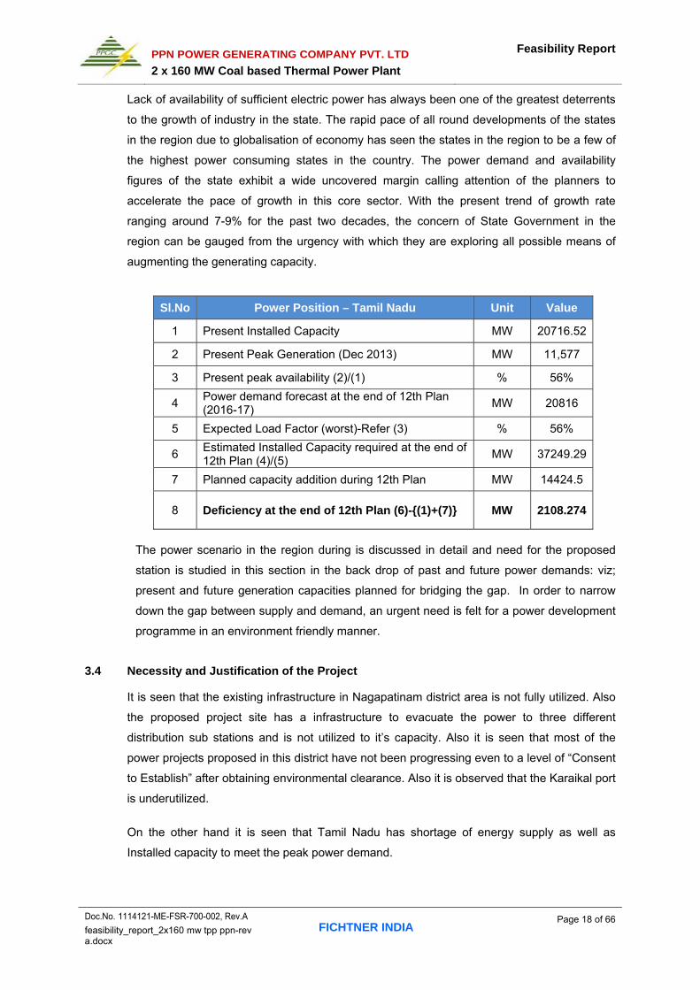
Lack of availability of sufficient electric power has always been one of the greatest deterrents
to the growth of industry in the state. The rapid pace of all round developments of the states
in the region due to globalisation of economy has seen the states in the region to be a few of
the highest power consuming states in the country. The power demand and availability
figures of the state exhibit a wide uncovered margin calling attention of the planners to
accelerate the pace of growth in this core sector. With the present trend of growth rate
ranging around 7-9% for the past two decades, the concern of State Government in the
region can be gauged from the urgency with which they are exploring all possible means of
augmenting the generating capacity.
Sl.No Power Position – Tamil Nadu Unit Value
1 Present Installed Capacity MW 20716.52
2 Present Peak Generation (Dec 2013) MW 11,577
3 Present peak availability (2)/(1) % 56%
4 Power demand forecast at the end of 12th Plan (2016-17)
MW 20816
5 Expected Load Factor (worst)-Refer (3) % 56%
6 Estimated Installed Capacity required at the end of 12th Plan (4)/(5)
MW 37249.29
7 Planned capacity addition during 12th Plan MW 14424.5
8 Deficiency at the end of 12th Plan (6)-{(1)+(7)} MW 2108.274
The power scenario in the region during is discussed in detail and need for the proposed
station is studied in this section in the back drop of past and future power demands: viz;
present and future generation capacities planned for bridging the gap. In order to narrow
down the gap between supply and demand, an urgent need is felt for a power development
programme in an environment friendly manner.
3.4 Necessity and Justification of the Project
It is seen that the existing infrastructure in Nagapatinam district area is not fully utilized. Also
the proposed project site has a infrastructure to evacuate the power to three different
distribution sub stations and is not utilized to it’s capacity. Also it is seen that most of the
power projects proposed in this district have not been progressing even to a level of “Consent
to Establish” after obtaining environmental clearance. Also it is observed that the Karaikal port
is underutilized.
On the other hand it is seen that Tamil Nadu has shortage of energy supply as well as
Installed capacity to meet the peak power demand.

PPN POWER GENERATING COMPANY PVT. LTD
2 x 160 MW Coal based Thermal Power Plant
Feasibility Report
Doc.No. 1114121-ME-FSR-700-002, Rev.A FICHTNER INDIA
Page 19 of 66 feasibility_report_2x160 mw tpp ppn-rev a.docx
Accordingly, PPN desires to establish additional capacity, which will be cost effective and
since there are no hurdles to be faced in establishing the infrastructure it can be brought into
operation without any delays or overrun. PPN intends to sell the power produced to Tamil
Nadu primarily thro’ case 1 bidding route.
It is also needs to be noted that PPN obtained Environmental and CRZ clearance to establish
a Combined cycle power plant of 1080 MW capacity at the same site location as proposed
now, but could not proceed on account of non availability of natural gas fuel and as per the
guidance of GOI in this regard. Also the following clearances have been obtained for the
earlier expansion project.
S.No. Description of
Permit Agency Remarks
1 Archaeological Monuments
Archaeological survey of India
AAI issued Map showing the heritage sites - protected monuments at Melaiyur and Tarangambai within a radius of 10 Km.
2 Wildlife Sanctuaries, National Park, Tigar Reserve, Biosphere Reserves
Tamil Nadu forest Department
No Reserve forest, reserve land and National park in 15 km radius from proposed project site boundary.
3 Chimney clearance Airport Authority of India AAI has no objection for construction of 3 chimneys (60 m height) for expansion combined cycle power plant.
4 Environmental Clearance
Ministry of Environmental & Forest
EC obtained for expansion by addition of 3x360MW Gas based CCPP.
5 Seawater Water Allocation
Tamil Nadu Marine Time Board
Clearance obtained for drawl of seawater using existing infrastructure.
6 CRZ clearance Ministry of Environmental & Forest
CRZ clearance for construction of marine facilities for drawl of seawater from Manhole 7 of the existing cooling water intake system.

PPN POWER GENERATING COMPANY PVT. LTD
2 x 160 MW Coal based Thermal Power Plant
Feasibility Report
Doc.No. 1114121-ME-FSR-700-002, Rev.A FICHTNER INDIA
Page 20 of 66 feasibility_report_2x160 mw tpp ppn-rev a.docx
4.0 PROJECT DESCRIPTION
4.1 Proposed Site Location
The proposed power project will be located adjacent to the existing plant location which is at
Pillaiperumalnallur and Manikkapangu villages near Thirukkadaiyur in Tharangambadi Taluka
of Nagapatinam District, Tamil Nadu.
GOOGLE MAP OF THE PROJECT SITE

PPN POWER GENERATING COMPANY PVT. LTD
2 x 160 MW Coal based Thermal Power Plant
Feasibility Report
Doc.No. 1114121-ME-FSR-700-002, Rev.A FICHTNER INDIA
Page 21 of 66 feasibility_report_2x160 mw tpp ppn-rev a.docx
4.2 Salient Technical Features
The detail technical description about existing and proposed thermal power plant is furnished
below.
4.2.1 Technical Features of Existing Combined Cycle Power Plant
4.2.1.1 Overview of existing CCPP
The plant with a nominal capacity of 330.5 MW is a dual fuel fired combined cycle power plant
using F class turbine technology. The gas turbine is operating in mixed fuel mode with
combination of naphtha and natural gas. Naphtha is delivered by ocean going 20,000 dwt
tankers and off loaded through a single point mooring system. Natural gas is transferred
through a dedicated pipeline to the site from nearby PY-01 offshore gas fields. The startup
fuel is HSD, which is transported through road tankers to the site.
The power plant is a single train dual fuel Gas Turbine Generator (GTG), Heat Recovery
Steam Generator (HRSG) and Steam Turbine Generator (STG) with the GTG capacity of 230
MW and STG capacity of 100.5 MW. The steam cycle is a reheat configuration. The steam
turbine condenser is cooled by seawater in a once through configuration with seawater intake
from Bay of Bengal.
Three floating roof fuel storage tanks of 28,000 m3 capacity are provided for naphtha storage
and two fixed roof storage tanks of 265 kLs tanks for HSD storage.
The transmission system consists of two double circuit 230 kV lines to Kadlangudi, one line to
Thanjavur and another line to Tiruvarur.
There is a colony by the side of the power plant to accommodate the O&M personnel. The
colony consists of 15 single-family houses and 48 two storied apartments in 12 blocks. There
is a hostel, canteen, recreation centre, open-air theater and Apollo medical center within the
premises catering to the needs of the plant personnel.
There is a dedicated domestic sewage treatment plant with in the colony to cater the needs
for the treatment of the domestic sewage from the colony and the plant. The treated water is
used for irrigation purposes in the green belt areas.
4.2.2 Technical Details of Existing CCPP
4.2.2.1 Gas Turbine Generator (GTG)
The Gas Turbine (GT) is a heavy duty, dual fuel, advanced class for naphtha and natural gas
fuels. The GT is equipped with steam injection facility to control NOx levels in the exhaust
gases to required concentrations. The generator is a direct driven, hydrogen cooled, 15 kV
synchronous machine.

PPN POWER GENERATING COMPANY PVT. LTD
2 x 160 MW Coal based Thermal Power Plant
Feasibility Report
Doc.No. 1114121-ME-FSR-700-002, Rev.A FICHTNER INDIA
Page 22 of 66 feasibility_report_2x160 mw tpp ppn-rev a.docx
GTG auxiliary systems consists of Lubricating oil, hydraulic oil, fuel gas, liquid fuel (Naphtha
and HSD for startup), Automated control system to optimize the steam injection and NOx
emission, hydrogen system, starting motor, torque converter, inlet air system ,exhaust
systems and online &off line compressor washing system.
4.2.2.2 Heat Recovery Steam Generator (HRSG)
The HRSG is an unfired, triple pressure, reheat, natural circulation, triple drum with horizontal
gas flow complete with Deaerator, safety valves, stop valves, economizer, evaporator, super
heater.
4.2.2.3 Steam Turbine Generator (STG)
The Steam Turbine is a single/double flow, reheat and condensing type. The generator is a
direct driven 13 KV, 50 Hz Synchronous machine.
STG Aux. consists of HP stop and control valves, IP stop and control valve, HP HRH and
Turbine bypass system, lube oil system, hydraulic oil, turning gear, sealing steam system,
excitation system etc.
4.2.2.4 Condensate and Feed Water System
The condensate system delivers condensate from the condenser hotwell to LP evaporator
section of the HRSG. The system includes two 100% capacity Condensate Extraction Pumps
(CEP), two 100% capacity vacuum pumps for air removal, a gland steam condenser and a
surface condenser with seawater cooling. The feed water system provides high pressure feed
water to the HP and IP economizer sections and to the HP / IP interstage desuperheaters.
Feed system provided with two 100% capacity Boiler Feed Pumps (BFP).
4.2.2.5 Main Steam System
The main steam system transports steam from HP super heaters of HRSG to HP stages of
Steam Turbine. The system includes steam bypass to condenser for plant start-up, super
heater and reheater interstage desuperheaters, drain connections for condensate collection
to prevent ST water damage and blow-down tank for drains and blow-down collection.
4.2.3 Existing CCPP Plant Auxiliary Systems
4.2.3.1 Raw Water System
The power plant's water requirement is met by using seawater. Out of 32,300 KL/hr of sea
water pumped, 99% is used for steam turbine main condenser cooling and auxiliary cooling
water system. The other 1.0% is used in Reverse Osmosis Plant to produce process water,
potable water, demineralised water for HRSG make up.

PPN POWER GENERATING COMPANY PVT. LTD
2 x 160 MW Coal based Thermal Power Plant
Feasibility Report
Doc.No. 1114121-ME-FSR-700-002, Rev.A FICHTNER INDIA
Page 23 of 66 feasibility_report_2x160 mw tpp ppn-rev a.docx
4.2.3.2 Once-Through Cooling Water System
The power plant is operating with a Once Through Cooling Water System. The plant cooling
water is drawn from the Bay of Bengal through 2.75 m dia. RCC pipe. The cooling water
pumphouse is located at about 500 m away from High Tide Level (HTL). The return cooling
water is discharged through 2.5 m dia. RCC pipeline to the seal pit and from there return to
sea after meeting the standards prescribed by the Tamil Nadu Pollution Control Board.
The cooling water system includes three cooling water pumps (3 x 50%, 2 W + 1 S), travelling
screens with screen wash pumps and a trash rack to prevent any debris entering into the
cooling water system.
The cooling water is supplied to the Steam condenser, closed cycle cooling water heat
exchangers and to Reverse Osmosis filtration system to meet the plant and colony water
requirements.
4.2.3.3 Closed Cycle Cooling Water System
The closed cycle cooling water system provides cooling for GTG, HRSG and STG Auxiliaries,
sample coolers, Boiler feed pumps, air compressors etc.,. The cooling medium is DM water
and the heat is rejected to seawater through plate heat exchangers.
4.2.3.4 Water Treatment Plant
Seawater is drawn and passed through a clarifier to remove the suspended solids followed by
a two-stage multi-media filtration system. This filtered water is pumped to the desalination
system, which consists of two stages of RO system.
Potable water from the first stage output of RO system is conditioned to WHO standards prior
to storing in the potable storage tanks.
The mixed-bed demineralization system takes water from the RO second stage for providing
makeup to HRSG feed water for steam cycle loss including NOx injection and evaporative
coolers. The mixed-bed demineralization system is regenerated with a dedicated acid and
caustic system.
4.2.3.5 Effluent Treatment System
Wastewater is treated in accordance with wastewater standards specifications before
discharge into seawater.
4.2.3.6 Sewage Treatment Plant
There is a dedicated domestic sewage treatment plant with in the colony to cater the needs
for the treatment of the domestic sewage from the colony and the plant. The treated water is
used for irrigation purposes in the green belt areas.
PPN POWER GENERATING COMPANY PVT. LTD
2 x 160 MW Coal based Thermal Power Plant
Feasibility Report
Doc.No. 1114121-ME-FSR-700-002, Rev.A FICHTNER INDIA
Page 24 of 66 feasibility_report_2x160 mw tpp ppn-rev a.docx
The microbial sludge from the sewage treatment plant is composed and used as a fertilizer
for the green belt development
4.2.3.7 Compressed Air System
Instrument and service air system includes two 100% oil-free air compressors connected in
parallel, two air receivers, a dual tower dryer and pre and after filters. Extraction air from Gas
Turbine compressor is provided as standby to instrument air.
4.2.3.8 Natural Gas System
Natural gas is supplied to plant boundary through pipeline and from there gas is passed
through a conditioning skid and fed to the gas turbine.
4.2.3.9 Fuel Oil System
Liquid fuel system is designed for naphtha delivery to the site by ocean-going tankers through
an oil pipeline to fill three on-site storage tanks each with a capacity of 28,000 m3. Presently
two tanks are in use and the third tank is kept as stand by.
Naphtha unloading and handling is done through a Single Point-Mooring (SPM) system.
Naphtha is pumped to the GT by two 100% capacity forwarding pumps.
HSD is used as the startup fuel when naphtha is fired in GT. It is unloaded from trucks into
untreated HSD tank of 265 KL capacity. It is stored in treated HSD tank of same capacity
after conditioning and then pumped to GT by two 100% capacity main HSD pumps.
4.2.3.10 Fire Protection System
Plant has a state of art fire protection system. It includes both active and passive protection
devices.
4.2.3.11 Switchyard
The plant is interconnected to the TNEB power grid through the 230kV ring bus switchyard
located adjacent to the power block. The electric power generated by GTG with a rated
voltage of 15 kV and STG with a rated voltage of 13 kV are evacuated through four numbers
of overhead feeders to TNEB substations in Kadlangudi, Tiruvarur and Thanjavur. The GTG
and STG are connected to the ring bus through step-up transformers with on-load tap
changers of 325 MVA and 130 MVA capacity respectively.
PPN POWER GENERATING COMPANY PVT. LTD
2 x 160 MW Coal based Thermal Power Plant
Feasibility Report
Doc.No. 1114121-ME-FSR-700-002, Rev.A FICHTNER INDIA
Page 25 of 66 feasibility_report_2x160 mw tpp ppn-rev a.docx
4.2.3.12 Start-up Power
During normal plant start up, power required for all plant auxiliaries is drawn from TNEB
through the switchyard and Station Service Transformer (SST). The SST of 22.5 MVA
capacity with on-load tap changer supplies power to 6.6kV switchgears of the plant power
distribution system.
4.2.3.13 Auxiliary Power
When GTG is operating and synchronized to TNEB grid, power for the plant auxiliaries is
provided from GTG output through a Unit Auxiliary Transformer (UAT) of 22.5 MVA capacity
with off-load tap changer.
4.2.3.14 Emergency Power
In the event of a total loss of power to auxiliaries or power from TNEB is not available, the
emergency power needed to keep critical process loads and emergency lightings in CCR /
SCR, GT enclosures and 6.6 kV switchgear room are provided by station batteries. For
prolonged isolation from TNEB grid, an emergency diesel generator of 700 KVA capacity is
provided to supply power to battery chargers, ST turning gear, emergency lightning and other
critical loads.
4.2.3.15 Medium and Low Voltage Switchgear
The 6.6 kV and 415 V switchgears are indoor, SF6 or Vacuum break, copper power bus,
surge protected, metal clad and with space heaters. All 6.6 kV switchgear breakers are
electrically operated from central Control Room (CCR).
The 415V switchgears are 3-phase and supplied by two delta-wye, dry type transformers and
solidly grounded. The 415 V switchgears supply power to low voltage distribution system
Motor Control Centres.
The Motor Control Centers (MCC) are indoor, 3-phase, 3-wired, copper power bus and supply
power to motors up to 2 x 160 kW, control circuits, lightning and distribution panel
transformers.
4.2.3.16 DC & UPS System
Two ungrounded direct current (DC) systems are provided, one for the STG and other plant
critical loads and the other for GTG and its critical loads, each with two 100% static battery
chargers. Each battery charger is designed to provide normal station DC load with both used
to simultaneously recharge the battery within 12 hours, Battery banks are of 1200 AH and
1100 AH capacity respectively with two-hour standby rating. Switchyard and CWPH have also

PPN POWER GENERATING COMPANY PVT. LTD
2 x 160 MW Coal based Thermal Power Plant
Feasibility Report
Doc.No. 1114121-ME-FSR-700-002, Rev.A FICHTNER INDIA
Page 26 of 66 feasibility_report_2x160 mw tpp ppn-rev a.docx
been provided with similar DC supply systems with battery banks of 2X300 AH and 65 AH
capacity respectively.
One ungrounded solid state Uninterrupted Power Supply (UPS) provides AC single –phase
power to critical AC loads in power block. An alternative 415 V AC source also provides
power via a static voltage stabilizer and a static transfer switch in the event of inverter failure.
In addition, a UPS is provided in CWPH to supply power to remote I/O bus and other critical
loads.
4.2.3.17 Control Systems
The plant is operated through a state of art Distributed Control System (DCS) from the
Central Control Room. The primary equipments GT and ST can be controlled and monitored
locally and also linked to DCS for controlling from CCR. The HRSG and balance of plant are
monitored, controlled and protected from CCR using the DCS. Emergency stop push buttons
for GT and ST and indications of HRSG drum levels and critical system alarms would been
hard-wired to CCR. The plant start-up and shutdown are through Automatic Plant Start-up
program (APS).
4.2.4 Environmental Management System
a. ISO 14001 and OHSAS 18001 Certification:
PPN had implemented Environment Management System from the day one and MIs.
DNV has certified the system from October 2002.
In addition their Occupational Health and Safety Management System are also has been
certified by M/s. DNV. PPN plant certified for both ISO 14001 and OHSAS 18001
simultaneously.
b. Continuous Emission Monitoring System:
Exhaust Flue gas from HRSG is dispersed through the 98m high Stack. PPN have
installed Continuous Emission Monitoring System (CEMS) to record NO (output of NOx).
S02. Temperature, O2, Dust Concentration and Gas Velocity at the Stack. The CEMS is
comprised of In-situ gas analyzers, which are mounted directly on the stack (at 68 m
level). Measured variables (4-20mA), as well as status alarm signals are transmitted
directly to remote control units and interfaced with the plants distributed control systems
(DCS). The gas analyzers include extensive self-diagnostics to survey all functions and
initiate alarms.
c. Weather Monitoring System:
Continuous Weather Monitoring System measures continuously Atmospheric
Temperature, Humidity, Wind Speed, Wind Direction, Atmospheric Pressure and Rain

PPN POWER GENERATING COMPANY PVT. LTD
2 x 160 MW Coal based Thermal Power Plant
Feasibility Report
Doc.No. 1114121-ME-FSR-700-002, Rev.A FICHTNER INDIA
Page 27 of 66 feasibility_report_2x160 mw tpp ppn-rev a.docx
Fall and records automatically and stored. The maximum, minimum and average of all the
parameters on daily and monthly basis are also computed automatically.
d. Ambient Air Quality Monitoring:
Ambient air quality in and around the plant is monitored at 6 locations within 6km radial
distance from the Power plant. To assess the impact of power plant operation in the
ambient air, environmental parameters like Total Suspended Particulate Matter (TSPM),
Respirable Particulate Matter (RPM), Sulfur Dioxide (SOx) Oxides of Nitrogen (NOx),
Carbon monoxide (CO), Lead and Ammonia (NH3) are monitored.
NOx is maintained below 35 ppmv against the max limit of 75 ppmv.
e. Ambient Noise Level Monitoring:
PPN Monitoring the ambient noise levels at different locations during day time and also
night time and equipment noise levels are also monitored.
f. Effluent Quantity Measurement and Quality Monitoring:
The wastewaters generated in the power plant facility are as follows;
1. Chlorine dosing to control marine growth in the cooling water system was replaced by
Environmental friendly Amine based biocide-Clamtrol.
2. Waste water generated in the RO plant like filter back wash water, RO reject water,
thickener overflow and neutralized effluent from the mixed bed Ion exchange unit are
pumped to sea water return line.
3. Oil bearing effluent from the naphtha and the HSD storage handling area, and
transformer areas are collected and treated in Tilled Plate interceptor units to bring
down the oil content and the treated effluent is pumped to the sea water return line.
PPN has installed flow meters to measure the flow of intake and effluent water at 6
locations and the flow trends are being monitored to control the process.
The Sewage effluents are being monitored in PPN laboratory regularly as per the
schedule. Samples are also collected and analysed by TNPCB at their laboratory at
Trichirapalli. In addition TNPCB is also monitoring the AAQ, Emission and Noise levels
periodically,
g. Underground / Surface Water & Soil Analysis:
As a part of above monitoring, samples were collected from the peripheral
ponds/underground wells and Soil in and around the plant and being analysed regularly.

PPN POWER GENERATING COMPANY PVT. LTD
2 x 160 MW Coal based Thermal Power Plant
Feasibility Report
Doc.No. 1114121-ME-FSR-700-002, Rev.A FICHTNER INDIA
Page 28 of 66 feasibility_report_2x160 mw tpp ppn-rev a.docx
h. Environmental Laboratory:
PPN has a full-fledged laboratory to cater to the need of a power plant both with regard to
environmental and process. PPN has experienced chemists to operate those equipments
and to diagnosis and take timely decision. PPN do Effluent Sample Analysis, Stack
Monitoring, Ambient Air Quality Monitoring, Weather Monitoring, Fuel Analysis, Water
Analysis, Potable Water Checking, and Process Chemical Parameters Checking etc.
PPN has envisaged instruments viz., Atomic Absorption Spectrophotometer, UV-Vis
Spectrophotometer, Gas Chromatograph, Ion Chromatograph, BOD Incubator etc
i. Rain Water Harvesting:
The total Built up area in the plant is 69,790 sq.m. The storm drains are designed in such
a way that the rainwater falling in that built up area is collected and stored in the
Rainwater Harvesting Pond. The total hold up volume of the pond is about 22,500 cum.
The collected water is improving the water table in the belt and is a main source for
developing and maintaining the Green Belt in and around the plant.
j. Green Belt Development:
PPN had planted more than 70,000 trees of different species like Naval, Neem, Copper
Pod, Coconut, Gulmohar, Odina etc. in the plant, colony and the side of the roads.
k. Managing Bio-degradable waste using Effective Micro-organism:
The vegetable/kitchen waste and the weeds/grass cutting wastes are collected and
converted into manure using Effective Micro-organism technique.
PPN also has an incinerator for disposal of the bio-medical waste generated in the
medical centre.
l. Off Site and On Site Emergency Drill:
PPN has on site and off site emergency plans prepared and got approved by the statutory
authorities. The offsite and on site drills are being conducted regularly by the plant
personnel and in the presence of the statutory authorities as well.
m. Plastic Free Zone:
The Plant Site is declared as Plastic Free Zone by the management and is implemented
very strictly. Awareness programs on Environment like World Environment Day,
Conservation of Water, Plastic Elimination, and Composting of Waste are being
conducted regularly.
n. Marine Biological Studies:
M/s National Institute of Oceanography(NIO) is doing the marine studies for PPN plant
from the Year 1995 and the latest study was done in April 2002.
PPN POWER GENERATING COMPANY PVT. LTD
2 x 160 MW Coal based Thermal Power Plant
Feasibility Report
Doc.No. 1114121-ME-FSR-700-002, Rev.A FICHTNER INDIA
Page 29 of 66 feasibility_report_2x160 mw tpp ppn-rev a.docx
o. Offshore marine emergency drill:
Marine Emergency Management Plan covering the offshore operation has been prepared
by the NIO and approved by the Coast Guard. Coast Guard, East Region, is conducting
marine offshore drill periodically.
p. Community Development Programme:
The company has employed sixty personnel for the operation and maintenance of the
power plant. In addition job has been provided to about 200 skilled and unskilled workers
(which include 20 women) through contracting for maintenance activities, security
services, fire crew, housekeeping, gardening, medical services etc.
a The Company voluntarily took up the matter of upgrading the education facilities at
Thirukkadaiyur and spent Rs.250 Lakhs till date to provide the Model Government
School in Nagapattinam District.
The company has built a new School building and handed over to the District
Education Authorities 2004.
Constructed a separate Building for Noon Meal Scheme.
All the Class Rooms were fully furnished and maintained from 2004
Compound wall was built and provided the playground with facility in 2005.
The school was equipped with all the necessary laboratory facilities in 2005.
Computer Lab was Equipped in 2005
Library was Established with Books and Furniture in 2005
Extended the School Building in 2006 and got upgraded to Plus 2 level.
Provided Stainless Steel Plates and Two Sets of Uniform to all the students
Solar powered RO Treatment Plant to produce drinking water was provided
a Provided Furniture to the Govt. Girls Higher Secondary School, Mayiladuthurai for
Rs. 2.5 Lakhs.
b Adopted the Thirukkadaiyur Primary Health Centre near the plant site and spent
Rs. 4 Lakhs for building renovation, procurement of hospital equipment's & furniture
in 2004. It is catering to the requirement of nearby 8 villages.
c Re-Iaid the Thirukkadaiyur to Piliaiperumainallur Road in 2004 for Rs. 40 Lakhs
d Cash awards are being given to students in Nagapattinam District who has obtained
first three ranks at the public examinations in 10th and 12th standards in State Board
as well as in Matriculation streams.
e Donated Rs. 5 Lakhs for the construction of the Sports Stadium at Nagapattinam.
f Contributed Rs. 1 Lakh for installing Circuit Camera and Traffic Signaling System at
Mayiladuthurai to Mayiladuthurai Police.

PPN POWER GENERATING COMPANY PVT. LTD
2 x 160 MW Coal based Thermal Power Plant
Feasibility Report
Doc.No. 1114121-ME-FSR-700-002, Rev.A FICHTNER INDIA
Page 30 of 66 feasibility_report_2x160 mw tpp ppn-rev a.docx
g Provided Reverse Osmosis Drinking Water Treatment Plant to the Office of
Superintend of Police, Nagapattinam in 2006 for Rs. 1 Lakh.
h Nagapattinam District was the worst affected district during the Tsunami in Dec.
2004. The company has extensively used its infrastructure for the relief activities like
rescue funeral, medical, food, clothing, resettlement etc.
i In addition the Company has contributed Rs. 25 Lakhs to Tsunami Relief Fund
j Sponsoring annual sports events during the Pongal festivals for the villagers.
k Provided Emergency Relief Corpus Fund of Rs. 1 Lakh for the use during any
emergency.
l Provided Braille equipment's for Nagai Library in March 2011.
m Donated 10 wheel chairs and 4 stretchers to Nagapattinam General Hospital in July
2011.
n Laid RCC/Bitumen Road between PPN Village to Thazhampettai via PPN Plant in
2011 for Rs.400 lakhs
o Construction of 3 Bus shelter and 7 Bore wells/Storage tanks is in progress at a cost
of Rs.I0 lakhs.
p Donated Tree guards 880 No's (Rs.8.8 lakhs worth) to Nagapattinam district collector
office, under the scheme massive Tree plantation programme in August 2012.
q Donated Tree guards 120 No's (Rs.1.2Iakhs worth) to Thirukadaiyur Government
Higher Secondary School in August 2012
r Donated Ambulance van to ISHA OUTREACH, Coimbatore in the year 2013.
s Free medical camp arranged for the villages of Pillaiperumalnallur in the year 2013.
t Donated Tree guards 200 No's (Rs.2 lakhs worth) to Nagapattinum SP Office. in
January 2014
q. Care Air Center
As directed by TNPCB, PPN have completed the establishment of connectivity with
TNPCB Care Air Centre of Tamil Nadu Pollution Control Board, Chennai. The details of
the signal which are presently monitored at CAC are furnished below:
i. NOx
ii. SO2
iii. Velocity of Flue gas (VS)
iv. Differential CW Temperature (∆T)
4.2.5 Tirukkadaiyur Minor port:
It is a dedicated port for the use of the power plant. The port facilities include:
Cooling water intake and discharge pipe lines
Single Point Mooring System
Naphtha Pipe line

PPN POWER GENERATING COMPANY PVT. LTD
2 x 160 MW Coal based Thermal Power Plant
Feasibility Report
Doc.No. 1114121-ME-FSR-700-002, Rev.A FICHTNER INDIA
Page 31 of 66 feasibility_report_2x160 mw tpp ppn-rev a.docx
RACON ( instead of Light House)
Automatic Identification System (AIS)
Navigational Bouys
Permanent Jetty
Line Boat and Tug Boat ( for Unloading Naphtha from ship)
Navigational Chart
24 hrs manned Port Control Room
Port and Customs Offices
NSPC & ISPS compliant port
4.2.6 Marine Facility
The existing marine facilities consist of Single Point Mooring (SPM) for unloading Naphtha,
600 mm dia. naphtha pipeline from SPM to the plant, 2750 mm dia. concrete intake pipeline,
seawater intake at 940 m offshore in 10.1 m water depth, 2500 mm dia. concrete outfall
pipeline and outfall diffuser at 415 m offshore in 5.1 m water depth. The volume of seawater
drawn presently is 32299 m³/h and Return water outfall volume of warm discharged into the
sea is 32191 m3/ hr. The outfall is having a multiple port diffuser system.
Location Geographical (WGS 84) UTM
Latitude, N Longitude, E X (m) Y (m)
Existing marine facilities
LFP 11°04’28” 79°51’25” 375161 1224466
Intake Dist.= 940 m Depth = 10.1 m
11°04’29” 79°51’53” 376015 1224482
Intake sump 11° 04’28” 79°51’04” 374525 1224464
Intake-MH-5 11° 04’28.46” 79°51’24.30” 375131 1224464
SPM 11° 04’30” 79°52’46” 377620 1224526
Outfall Dist.= 415 m Depth = 5.1 m
11° 04’29” 79°51’36” 375487 1224498
Proposed facilities – bifurcation of pipelines
Intake sump – onshore
11° 04’22” 79°50’17” 373081 1224288
Intake bifurcation MH-7 (onshore)
11°04’28.20” 79°51’11.02” 374728 1224458
Outfall joining seal pit (onshore)
11° 04’28” 79°51’04” 374525 1224464

PPN POWER GENERATING COMPANY PVT. LTD
2 x 160 MW Coal based Thermal Power Plant
Feasibility Report
Doc.No. 1114121-ME-FSR-700-002, Rev.A FICHTNER INDIA
Page 32 of 66 feasibility_report_2x160 mw tpp ppn-rev a.docx
4.2.7 Features of Proposed Power Plant
4.2.7.1 Unit Site Selection
The power demand scenario in Southern region reveals that the power demand will continue
to exceed the available and planned generation capacity in the years to come. Also the
rapidly increasing industrial development and per capita energy consumption levels as a
result of improvement in the standard of living in urban and rural areas, agricultural growth,
etc. will increase the power demand to a greater extent.
Any solid fuel based power plant unit can achieve an availability of around 90% only taking
into account the statutory annual shut down requirements for the steam generator equipment.
The tariff can be kept down only when generation of power is maximized utilising the
infrastructure already established. The area availability for the power plant, environmental
requirements, water resources and fuel logistics play a vital role in selection of the unit
capacity.
With the available land, fuel logistics and taken into account of all the above, it is proposed to
install the coal fired thermal power plant of capacity 2 X 160MW.
The exact gross capacity of the plant would depend upon the proven design of the Boiler and
Steam Turbine – Generator that is available with manufacturers. For the purpose of
equipment / systems sizing and for project cost estimates; the plant gross capacity has been
considered as 2 x 160 MW and in no case the selected gross capacity of each unit will
exceed 160 MW.
4.2.7.2 Technology Selection
Technology options available are Pulverized Fuel (PF) fired boiler and Circular Fluidized Bed
combustion (CFBC) Boiler.
The 2 x 160 MW units will be established with PF boiler. It will operate with imported coal of 1
% sulphur maximum and ash of 12 % maximum .
4.2.7.3 Power Cycle
The Steam generator which would be designed for firing 100% imported coal would be
radiant, reheat, natural circulation, single drum, balanced draft, outdoor type of unit rated to
deliver about 467 t/hr of superheated steam at 130 bar, 543°C when supplied with feed water
at a temperature of 239°C at the economiser inlet.

PPN POWER GENERATING COMPANY PVT. LTD
2 x 160 MW Coal based Thermal Power Plant
Feasibility Report
Doc.No. 1114121-ME-FSR-700-002, Rev.A FICHTNER INDIA
Page 33 of 66 feasibility_report_2x160 mw tpp ppn-rev a.docx
The combustion system will be provided for pulverised coal firing with Low NOx type coal
burners. The steam generator will be designed for continuous satisfactory operation with the
range of Imported coal expected for this station without any need for auxiliary fuel oil for flame
stabilisation. The furnace would be conservatively designed for fuel to burn completely and to
avoid any slagging in the furnace and excessive fouling in the superheater sections of the
boiler. The design flue gas velocities would be carefully selected to minimise erosion of
pressure parts and other vital components on account of ash. The steam generator would be
designed in accordance with the latest provisions of Indian Boiler Regulations.
Capacity of steam generating unit would be so selected as to ensure adequate margin over
the requirement of Turbine at 100% MCR in order to cater to auxiliary steam requirement for
soot blowing operation, and derating of the steam generating unit after prolonged use. The
steam generator would be designed to operate with “the HP Heaters out of service” condition
(resulting in lower feed water temperature at Economiser inlet) and deliver steam to meet the
turbo-generator requirement at base load. Economiser section of the boiler would be non-
steaming type with provision for recirculation during start-up, chemical cleaning etc.
Superheater section would be divided in convection and radiant zones and designed so as to
maintain rated steam temperature of 543°C (±5°) at outlet over the range of 60% to 100%
MCR load. Main steam desuperheating stations with provision for spraying water tapped off
from feed water piping would be provided. Air preheater, preferably of rotary type would be
provided with a set of soot blowers of automatic sequential electrically operated type,
arranged for on-load cleaning of the heat transfer surfaces.
Draft system of boiler would be provided with two (2) Forced Draft and two (2) Induced Draft
Fans with suitable capacity and control arrangement, each independently capable of meeting
the requirement at 60% boiler MCR load. The forced draft fans would control total airflow to
boiler and the induced draft fans will control furnace draft of the boiler through automatic
control loops. This unit will be equipped with suitable imported coal firing system. The coal will
be received to the coal bunkers of about 24 hours storage capacity on Imported coal and the
same will be fed to the coal pulverises utilising gravimetric feeders. The pulverised and
conditioned coal will be then distributed to the Low NOx coal burners from each mill for
combustion in the furnace of the boiler thro’ coal conveying pipes. It is considered that even
with one pulverising coal mill out of service it will be possible to achieve 100 % MCR even
when firing the Imported coal.
The steam generating unit will be provided with arrangement for start-up and at low load
stabilisation periods when firing coal utilising liquid fuel such as LDO/Fuel oil.
The drum level measurement will include Direct Level gauge glass, Bi-colour gauge glass,
remote level indication and recording in plant control room etc.

PPN POWER GENERATING COMPANY PVT. LTD
2 x 160 MW Coal based Thermal Power Plant
Feasibility Report
Doc.No. 1114121-ME-FSR-700-002, Rev.A FICHTNER INDIA
Page 34 of 66 feasibility_report_2x160 mw tpp ppn-rev a.docx
The complete boiler will be top supported type and would be provided with all supporting steel
structures, platforms, galleries, elevator and stairways for easy approach and maintenance of
the unit. Adequate weather protection would be provided for instruments and operating
personnel.
Necessary lining and insulation along with fixing materials to limit outside surface temperature
to a safe level would be provided. Monorails and hoists required for handling heavy
equipment, motors, fans etc. would be supplied along with the steam-generating unit for ease
of maintenance.
The steam-generating unit would be provided with electro-static precipitator. The precipitator
will have two parallel gas paths, any of which can be isolated for maintenance when required,
keeping the other path in operation. Each path will have (n+1) fields in series for collection of
fly ash, of which, (n) fields will be in service and the other one will remain as a standby. The
ESP will be such that the outlet dust burden does not exceed 50 mg/Nm3 at 100% MCR.
One no. of double flue chimney of 220 m height is proposed for effective dispersion of the
pollutants.The chimney height has been considered in accordance with the guidelines given
by the MoEF/Central Pollution Control Board.
For the unit size of gross capacity of 2x160 MW the most common steam turbine prevalent is
a single reheat, regenerative cycle configuration with six uncontrolled extractions for
regenerative feed heating. These units utilize main and hot reheat steam at a temperature
540°C / 540°C at turbine inlet. At TMCR condition, the main steam inlet pressure is 125 ATA
and the reheat steam pressures will be in the order of 30 ATA. At Turbine valve wide open
(VWO) condition the Turbo-generator set will be able to operate continuously at throttle steam
flow of about 105% of turbine MCR condition.
All auxiliaries like Lube oil system, turbine oil purification system, turning gear etc. as well as
necessary protective and supervisory system will be provided to ensure trouble-free, safe and
efficient operation of the turbo-generator.
HP and LP turbine bypass station will be provided as a part of turbine package. The bypass
station will act not only as a protection to the unit during pressure rise resulting from sudden
load throw off but also enable operation of the unit at loads lower than the controllable range
of load.
The feed water heating plant includes three low pressure heater, de-aerator and two high
pressure heaters. With this configuration a final feed water temperature of about 240 deg C

PPN POWER GENERATING COMPANY PVT. LTD
2 x 160 MW Coal based Thermal Power Plant
Feasibility Report
Doc.No. 1114121-ME-FSR-700-002, Rev.A FICHTNER INDIA
Page 35 of 66 feasibility_report_2x160 mw tpp ppn-rev a.docx
is maintained. Deaerator will be of spray-cum-tray type with a separate horizontal storage
tank for feed water. The Deaerator will be of variable pressure type. LP/HP Heaters will be of
horizontal /vertical type with stainless steel tubes.
The condenser will be of two pass surface condenser capable of maintaining the required
vacuum while condensing maximum steam flow through LP turbine will be provided. The
divided water box arrangement will be such that it is possible to isolate one half of the
condenser from cooling water inlet and outlet sides.
Condensate extraction pumps will be of 3 x 50 % capacity motor driven units.Three (3) 50%,
horizontal, multistage, barrel casing centrifugal type boiler feed pumps, driven by electric
motor, will be provided. Each boiler feed pump will have one (1) matching capacity single
stage booster pump driven by the feed pump motor.
4.3 Generator
Generator will be directly driven by steam turbine at 3000 rpm. The Generator and its
excitation system will have a capability at least matching the declared maximum continuous
rated output of the associated steam turbine, for the specified cooling at all power factors
between 0.85 lagging and 0.95 leading with +3% to -5% frequency variation, terminal voltage
variation of +/-5% and combined voltage & frequency variation of 5%. Generator voltage will
be in the range of 15-18 kV as per manufacturer’s standard.
Generator will be able to satisfy transmission load reactive requirements under all reasonable
anticipated operating conditions. The generator excitation system will be brushless type with
PMG or with Static Excitation system or any other modern excitation system to suit the
system.
The generator will be direct hydrogen cooled. Generator will be supplied with hydrogen
cooling system, and carbon dioxide supply system for purging of hydrogen and seal oil
system.
4.4 Water System
4.4.1 Intake System
The power station will have to depend upon seawater to meet the water requirement for
cooling water system and for other applications such as power cycle make up, potable water,
service water etc. The proposed plant site is located approximately 2.5 km from Bay of
Bengal.
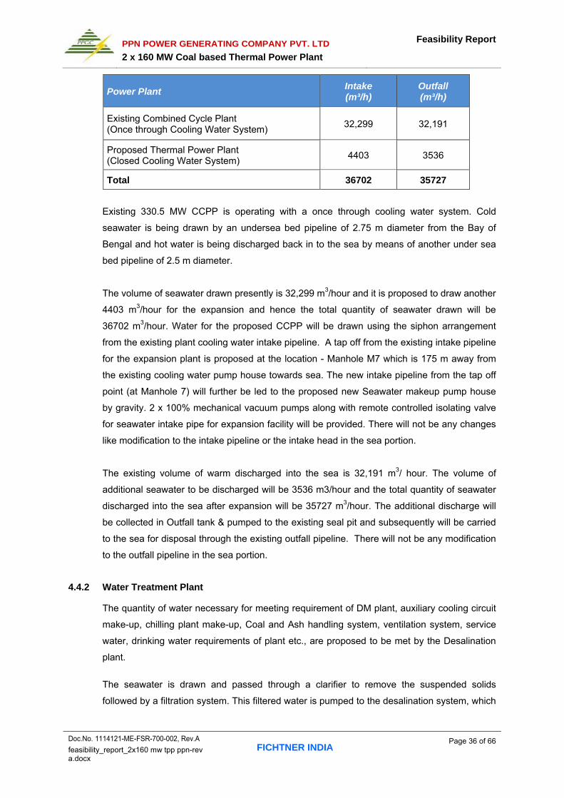
PPN POWER GENERATING COMPANY PVT. LTD
2 x 160 MW Coal based Thermal Power Plant
Feasibility Report
Doc.No. 1114121-ME-FSR-700-002, Rev.A FICHTNER INDIA
Page 36 of 66 feasibility_report_2x160 mw tpp ppn-rev a.docx
Power Plant Intake (m³/h)
Outfall (m³/h)
Existing Combined Cycle Plant (Once through Cooling Water System)
32,299 32,191
Proposed Thermal Power Plant (Closed Cooling Water System)
4403 3536
Total 36702 35727
Existing 330.5 MW CCPP is operating with a once through cooling water system. Cold
seawater is being drawn by an undersea bed pipeline of 2.75 m diameter from the Bay of
Bengal and hot water is being discharged back in to the sea by means of another under sea
bed pipeline of 2.5 m diameter.
The volume of seawater drawn presently is 32,299 m3/hour and it is proposed to draw another
4403 m3/hour for the expansion and hence the total quantity of seawater drawn will be
36702 m3/hour. Water for the proposed CCPP will be drawn using the siphon arrangement
from the existing plant cooling water intake pipeline. A tap off from the existing intake pipeline
for the expansion plant is proposed at the location - Manhole M7 which is 175 m away from
the existing cooling water pump house towards sea. The new intake pipeline from the tap off
point (at Manhole 7) will further be led to the proposed new Seawater makeup pump house
by gravity. 2 x 100% mechanical vacuum pumps along with remote controlled isolating valve
for seawater intake pipe for expansion facility will be provided. There will not be any changes
like modification to the intake pipeline or the intake head in the sea portion.
The existing volume of warm discharged into the sea is 32,191 m3/ hour. The volume of
additional seawater to be discharged will be 3536 m3/hour and the total quantity of seawater
discharged into the sea after expansion will be 35727 m3/hour. The additional discharge will
be collected in Outfall tank & pumped to the existing seal pit and subsequently will be carried
to the sea for disposal through the existing outfall pipeline. There will not be any modification
to the outfall pipeline in the sea portion.
4.4.2 Water Treatment Plant
The quantity of water necessary for meeting requirement of DM plant, auxiliary cooling circuit
make-up, chilling plant make-up, Coal and Ash handling system, ventilation system, service
water, drinking water requirements of plant etc., are proposed to be met by the Desalination
plant.
The seawater is drawn and passed through a clarifier to remove the suspended solids
followed by a filtration system. This filtered water is pumped to the desalination system, which

PPN POWER GENERATING COMPANY PVT. LTD
2 x 160 MW Coal based Thermal Power Plant
Feasibility Report
Doc.No. 1114121-ME-FSR-700-002, Rev.A FICHTNER INDIA
Page 37 of 66 feasibility_report_2x160 mw tpp ppn-rev a.docx
consists of two stages of RO system. The potable water from the RO system is conditioned to
WHO standards prior to storing in the potable storage tanks.
The mixed-bed demineralization system takes water from the RO second stage for providing
cycle makeup. The mixed-bed demineralization system is regenerated with a dedicated acid
and caustic system.
The total sea water requirement for the proposed project is about 4403 m3/hr. Out of this,
about 3536 m3/hr (primarily cooling tower blow down and RO plant reject water) would be
discharged back to the sea and about 734 m3/hr would be lost through evaporation in the
cooling towers. About 133 m3/hr of desalinated water (net) would be used for meeting the
various fresh water requirements of the plant.
Waste water generated in the RO plant like filter back wash water, RO reject water, thickener
overflow and neutralized effluent from the mixed bed Ion exchange unit, boiler blow down
water etc., are pumped to outfall tank arrangement from which it will be delivered by a pump
to the existing plant seal pit which delivers the sea water back to the sea thro’ the existing sea
water outfall system.
4.4.3 DM Plant
The purpose of the DM plant is to produce Demineralized water of required quality and
quantity of steam cycle and DMCW system. The DM Plant will treat clarified/Desalinated
water to produce Demineralized water for make up to steam cycle, closed cooling water
system and other uses.
Water balance diagram for the proposed project is given in Exihibit-3.
4.5 Raw Material
4.5.1 Source and Type of Fuel
Indonesian coal will be considered as the imported coal for the proposed project.
The Plant will be designed for 100% imported coal.
4.5.2 Coal Linkage & Transportation
Indian Coal linkage is not considered for the project usage. The Imported coal will be received
at Karaikal port and transported to site by trucks / Railway siding.
Capabilities at Karaikal Port
The port has a bulk material handling capability for 21 Million tons per annum and it is an
all weather port.

PPN POWER GENERATING COMPANY PVT. LTD
2 x 160 MW Coal based Thermal Power Plant
Feasibility Report
Doc.No. 1114121-ME-FSR-700-002, Rev.A FICHTNER INDIA
Page 38 of 66 feasibility_report_2x160 mw tpp ppn-rev a.docx
Currently handling 6.5 million tons of commodities out of which almost 5 million tons is
imported coal – mainly from Indonesia and coal from South Africa and Australia are also
being received. It is understood that about 0.6 million tons of Pet Coke is being imported
from USA.
Currently coal, gypsum and limestone are being imported by cement/steel plant in Tamil
Nadu.
Current consignments move through road and about 12 rakes through rail.
Currently port has capability to unload coal of about 18000 tons/day from the ships and
70000 Tons PANAMAX ships are being received. It is seen that automation to unload,
store and load to trucks or rail is being established.
17 T trucks are being handled in the port.
The project will use this infrastructure for its requirements as it has adequate unutilized
capacity.
Road transportation by Trucks
Road transportation is envisaged for unit 1 and in respect of unit 2I coal transportation by rail
is proposed.
Loaded trucks at Karaikal Port have to be transported to Power Plant for ~35km using ECR.
This has to pass through the Karaikal town where the roads and infrastructure are not
sufficient. There is a proposal (currently field execution is progressing) for the development
of bypass on the western side of Karaikal which will clear the hurdle and will make easy the
road transportation. Once the truck reaches the southern entry point of Thirukadaiyur town it
needs to take the existing kutcha road which runs along the southern boundary the PPN
asset. The existing kutcha road is not suitable for truck movement as it is narrow and has
sharp curves. Hence, this road leading to southern boundary of PPN asset needs to be
widened and improved for truck movement. A detailed study on coal transportation is under
progress for establishing the coal transportation right of way requirements.
Typical coal truck catalogue is furnished in Exhibit – 05A. Coal transportation by Rail The feasibility study for rail transportation from Karaikal port to the nearest railway station and
further to the project site is being undertaken and details will be included in the EIA report.
Proposed Railway Line near the site is furnished in Exhibit – 05B.

PPN POWER GENERATING COMPANY PVT. LTD
2 x 160 MW Coal based Thermal Power Plant
Feasibility Report
Doc.No. 1114121-ME-FSR-700-002, Rev.A FICHTNER INDIA
Page 39 of 66 feasibility_report_2x160 mw tpp ppn-rev a.docx
4.5.3 Coal Handling System
Coal handling system will be designed based on worst range of coal as specified. The coal
analysis considered for design is furnished in Appendix-02. A brief description of the
proposed coal handling system is furnished below:
The coal handling system comprises the following:
4.5.3.1 Unloading System, screening and crushing & Bunker Feeding System
Truck Unloading System
Coal will be received at the plant by Trucks. The coal from the trucks will be unloaded into
the ground hoppers. Six (6) Nos. of ground hoppers with feeders is proposed to be
installed for unloading coal. Feeders will be located below the outlet of each ground
hopper and will feed the coal onto the belt conveyor for further feeding to screening and
crushing process.
Screening and crushing & Bunker Feeding System Coal will be fed to screen and crusher for screening and crushing process respectively
and the output will be sent for storage / bunker through a series of belt conveyors.
4.5.3.2 Stacking, Reclaiming and Bunker Feeding System
Stacking
When boiler bunkers are full, the crushed coal will be diverted to covered stockpile.
Storage capacity will be about 30,000 T.
Reclaiming and Bunker Feeding System The coal from covered stockpile will be reclaimed and will be feeding coal to coal bunkers
through series of conveyors.
4.5.4 Ash Handling System
Ash handling system will be designed based on worst range of coal as specified. The Ash
handling system comprises the following:
Bottom Ash Removal System in PF Boiler
Bottom ash formed due to the combustion of coal in the SG shall be collected in a
refractory lined dry Bottom Ash Hopper (BAH). In this system, the bottom ash from
the boiler furnace shall be discharged into the submerged scraper chain conveyor
provided below the dry type bottom ash hopper. The scraper chain conveyor in turn
shall feed bottom ash to clinker grinder where it gets crushed and feeds the buffer
PPN POWER GENERATING COMPANY PVT. LTD
2 x 160 MW Coal based Thermal Power Plant
Feasibility Report
Doc.No. 1114121-ME-FSR-700-002, Rev.A FICHTNER INDIA
Page 40 of 66 feasibility_report_2x160 mw tpp ppn-rev a.docx
hopper. Further it will be disposed to ash pond using jet pump. Provision for
disposing in semi wet mode will be provided in buffer hopper/silo.
Fly Ash Removal System
The fly ash collected in several sets of hoppers located in the flue gas path viz.,
economizer ash hopper, ESP hoppers, air pre-heater hoppers etc will be evacuated
pneumatically. The fly ash is sequentially extracted from these hoppers by dense phase
system and conveyed to Fly ash storage silos
Ash Disposal
Ash will be disposed in following modes:
Bottom ash:
Semi wet mode: Ash from the buffer hopper/silo will be loaded in to open trucks in semi
wet mode.
Wet mode: In emergency case, ash from buffer hopper/silo will be conveyed to the ash
pond using jet pumps. Lean phase system will be adopted.
Fly ash
Dry mode: Dry ash from the silos will be loaded in to closed trucks for utilization purpose. Semi wet mode: Ash from the silos will be loaded in to open trucks using ash conditioner
in semi wet mode.
Wet mode: In emergency case, ash from silo will be conveyed to the ash pond using jet
pumps. Lean phase system will be adopted.
Ash Pond
Ash will be transported to ash pond in the land identified near the main plant. Ash slurry
will be dumped into the ash pond would be contained in the ash pond by constructing
bunds around the periphery of the ash pond. HDPE liner thickness of the ash pond will be
established to limit permeability to the required level and as required to resist tears and
punctures due to placement of the top soil on it. Recovery water system will be provided
near the ash pond.
This pond would accommodate
Bottom ash in wet disposal condition for the period of 25 years.
Fly ash disposed in wet disposal condition progressively as follows: Atleast 50% of fly ash generation : One year from the date of commissioning
Atleast 70% of fly ash generation : Two year from the date of commissioning
Atleast 90% of fly ash generation : Three year from the date of commissioning

PPN POWER GENERATING COMPANY PVT. LTD
2 x 160 MW Coal based Thermal Power Plant
Feasibility Report
Doc.No. 1114121-ME-FSR-700-002, Rev.A FICHTNER INDIA
Page 41 of 66 feasibility_report_2x160 mw tpp ppn-rev a.docx
Atleast 100% of fly ash generation : Four year from the date of commissioning
Efforts will be made for achieving 100% fly ash utilization from fourth year onwards.
Land requirement for ash disposal will be about 20 acres considering the bund height
of 25m. Bund height will be subsequently increased to accommodate more capacity.
Ash water Recovery System
Ash pond decanted water will be treated and reuse in ash handling system. The water
from the stilling pond will be let out through the collecting well. The effluent outflow from
these collecting wells will be gravity led through a discharge pipe to recovery water sump
(close to ash pond).
Water from collection sump will be pumped to clariflocculator by using recovery water
pumps. The clarifier will be located partially above ground. The dosing system will pump
measured quantity of coagulant solution into flash mixer of clariflocculator. The water
from the clariflocculator will be led in to an ash water tank by gravity through open
channel located above ground. The total suspended solids of the recovered clear water
will be less than 100 ppm.
Whenever ashes are disposed in dry mode and excess water during rainfall, clear water
will be taken to sea water outfall.
4.5.6 Cooling Water System
Sea water cooling is proposed for the cooling water system. As the site is located about
2.5 km from the sea, the preferred option is to go in for open cycle cooling system with sea
water makeup. The cooling water system will comprise mechanical draft counter flow type
cooling towers suitable for Sea water recirculation with cooling tower basin, circulating water
pumps and cooling water piping. The CW system blow down is effected from CW fore bay
which is the cold side of the CW system. Blow down pumps are provided to pump water to
the sea water outfall through a pipeline. A detailed seawater water analysis is given in
Appendix-04.
4.5.7 Fuel Oil System
The Fuel oil system provides the facility for unloading, storage, supply and forwarding of Light
Diesel Oil. HFO/LDO will be transported through Road tankers. Fuel oil consumption for the
proposed project will be about 1200 KL /annum.
4.5.8 Compressed Air System

PPN POWER GENERATING COMPANY PVT. LTD
2 x 160 MW Coal based Thermal Power Plant
Feasibility Report
Doc.No. 1114121-ME-FSR-700-002, Rev.A FICHTNER INDIA
Page 42 of 66 feasibility_report_2x160 mw tpp ppn-rev a.docx
Compressed air would be required for instrumentation applications and service utilities.
Quality air would be required for instrumentation and control of the power plant equipments
including operation of various pneumatically operated valves, actuators etc. Service air would
be required for boiler utilities like HEA purging, APH auxiliary air motor, atomizing air for LDO
firing, etc as well as general service air for cleaning purposes.
4.5.9 Fire Fighting System
Fire fighting system will be designed in conformity with the recommendations of the Tariff
Advisory Committee of Insurance Association of India. Codes and Standards of National Fire
Protection Association (NFPA), USA will be followed, as applicable.
4.5.10 Other Plant auxiliaries
The other plant auxiliaries such as Ventilation & Air condition system, Mill reject system,
Effluent treatment systems, Cranes & Hoists, Elevators, Chemical laboratory etc., will be
designed to meet the plant requirement.
4.5.11 Non Plant facility
The infrastructure facilities like administrative buildings, service building, security buildings
canteen etc., will be developed as a part of the project.
4.6 Electrical System
230kV indoor Gas Insulated Switchyard (GIS) with Double Main bus arrangement will be
provided considering the space availability and the plant being located near sea.
Generator Circuit Breaker (GCB) scheme is envisaged with one number Generator
Transformer (GT), one number Unit Auxiliary Transformer (UAT) and one number Station
Transformer (ST) for each unit. The start-up power required for station auxiliaries and unit
auxiliaries will be drawn from 230kV grid through the above mentioned GIS.
Auxiliary power supply is envisaged at two levels viz., 6.6kV and 415V to provide power for all
the drives and equipment in the power plant. 6.6kV power supply for auxiliaries will be derived
from UAT and ST secondary. 415V supply will be derived from 6.6kV boards through service
transformers.
In the event of total black out, to provide emergency AC supply for safe shut down of the unit,
one number DG set is envisaged for each unit along with one number common standby DG
set.

PPN POWER GENERATING COMPANY PVT. LTD
2 x 160 MW Coal based Thermal Power Plant
Feasibility Report
Doc.No. 1114121-ME-FSR-700-002, Rev.A FICHTNER INDIA
Page 43 of 66 feasibility_report_2x160 mw tpp ppn-rev a.docx
4.7 Control and Instrumentation System
Distributed control system dedicated is envisaged for BTG control, monitoring and operations.
PLC/DCS Remote IO system is envisaged for BOP & its auxiliaries control and monitoring.
PLC/DCS Remote IO system interfacing to the BTG DCS is envisaged.

PPN POWER GENERATING COMPANY PVT. LTD
2 x 160 MW Coal based Thermal Power Plant
Feasibility Report
Doc.No. 1114121-ME-FSR-700-002, Rev.A FICHTNER INDIA
Page 44 of 66 feasibility_report_2x160 mw tpp ppn-rev a.docx
5.0 ENVIRONMENTAL AND POLLUTION ASPECTS The major environmental concerns for putting up the proposed power station are as follows; a) Air pollution
b) Water pollution
c) Thermal Pollution
d) Noise pollution
5.1 Air Pollution
The Air pollutants from the proposed units are:
Particulate matter
Nitrogen oxides in flue gas
Sulphur dioxide in flue gas
Carbon monoxide in flue gas
Coal dust particles during storage/handling
The Air pollutants from the proposed units will be controlled by selecting the appropriate
equipment/systems. Mitigation measures to limit the above air pollutions are to be
investigated in detail through an Environmental Impact Assessment Study to satisfy ambient
air quality standards.
Particulate Matter
For thermal power stations, depending upon the requirement of local situation, such as
protected area, the State Pollution Control Boards and other implementing agencies under
the Environment (Protection) Act, 1986, prescribe a limit of 100 mg/Nm3 for particulate matter,
irrespective of generation capacity of the plant.
The efficiency of the ESP will be 99.9%, which remove most of the fly ash from the flue gas
thereby limiting the quantity of fly ash emitted to atmosphere to about 50 mg/Nm3and the
height of the stack which disperses the pollutants has been fixed at 220 m to meet the norms
of Central Pollution Control Board (CPCB).
Nitrogen Oxides (NOx) Emissions
Presently there are no limitations for NOx emissions from the coal fired power plants.
Sulphur dioxide (SO2) Emissions Presently there is no legislation or norms for limiting the SO2 emissions from coal based
thermal power plants. Currently sulphur dioxide levels are controlled by dispersing the
pollutant to atmosphere through a tall stack. Minimum stack height recommended by CPCB
formula is indicated below:

PPN POWER GENERATING COMPANY PVT. LTD
2 x 160 MW Coal based Thermal Power Plant
Feasibility Report
Doc.No. 1114121-ME-FSR-700-002, Rev.A FICHTNER INDIA
Page 45 of 66 feasibility_report_2x160 mw tpp ppn-rev a.docx
H = 14 x Q0.3
Where,
H is chimney height in meter
Q is quantity of Sulphur dioxide in kg/hr.
With Sulphur content in coal about 1%, Sulphur dioxide emission rate will be 3209 kg/h
(140.44 Nm3/sec, gas temperature 139oC). Chimney with twin flue having a height of 220
meter and exit diameter of 3.4 m will be provided for proposed plant. A provision is made in
the plant layout for installing a FGD plant in future if required to meet stationary requirement.
based on the boiler technology selected.
CO Emissions Carbon monoxide (CO) another kind of pollutant hardly exists in the modern power stations
as design of combustion control equipment and the furnace eliminates, almost completely the
possibility of incomplete combustion.
Dust
Dust generated in the Coal handling area would be minimised by providing suitable dust
suppression/extraction systems. For the coal stockyard, dust suppression system would be
provided. Boiler bunkers would be provided with ventilation system with bag filters to trap the
dust in the bunkers.
5.1.1 Water Pollution
During project operation phase, the following liquid wastes are expected to be generated from
the following sources:
Cooling water blow down.
Sewage from plant.
Runoff from coal stock piles.
Effluent from bottom ash handling system
Floor wash waste.
Desalination plant reject
DM plant effluent
Waste Water
According to the Central Pollution Control Board stipulation, the thermal power plants using
sea water should adopt suitable system to reduce water temperature at the final discharge
point so that the resultant rise in the temperature of receiving water does not exceed 5oC over
and above the ambient temperature of receiving water bodies. For the proposed power plant,

PPN POWER GENERATING COMPANY PVT. LTD
2 x 160 MW Coal based Thermal Power Plant
Feasibility Report
Doc.No. 1114121-ME-FSR-700-002, Rev.A FICHTNER INDIA
Page 46 of 66 feasibility_report_2x160 mw tpp ppn-rev a.docx
a closed cooling water system is adopted and in order to limit the temperature of seawater
discharged to sea, blow down from the plant is considered from cold side of cooling water.
Therefore the temperature of reject seawater at point of discharge will be same as cold
cooling water temperature.
The effluents generated from the plant, both process as well as sea water effluents, after
collection in the outfall tank will be sent to existing seal pit near existing sea water intake
pump house. Effluents will meet the standards prescribed by the TNPCB / MoEF / CPCB.
Measurement of effluent parameters will be carried out at outfall tank. The existing plant
discharge arrangements (downstream of existing seal pit) will continue to be utilised for
disposal.
5.1.2 Noise Pollution
Several noise suppression and attenuation features will be designed in the plant for the
protection of personnel at all normally accessible locations within the plant boundary, both
inside and outside the different buildings, and for the protection of the inhabitants living in the
vicinity of the power plant.
5.2 Ash Disposal and Utilization
The ash generated by the plant will be utilized for commercial purposes and unutilized fly ash
and bottom ash will be pumped in slurry form to ash pond located on 20 acres of land
approximately, within the project area. Ash pond recovery water will be treated and reuse in
ash handling system. Ash water recovery system consists of clariflocculator and dosing
system. Clear water will be led into ash water tank.
Admixing fly ash into cement is gaining momentum and cement manufacturers may express
their desire to either set up their grinding and blending plants near thermal power stations or
procure fly ash for their use. Further ash generated from the proposed power plant can also
be utilized in Building/construction industry, Land developments, Roads & embankments, Ash
dyke rising, Other medium & high value added products (Ceramic tiles, wood, paints)
pavement blocks, light weight aggregate, extraction of alumina etc.,
5.3 Green Belt
The landscaping and ground cover system is meant to enhance the appearance of selected
areas, enhance soil and slope stabilization of the land of the power plant, and assist in
reducing the noise level and fugitive dust generated by the plant.

PPN POWER GENERATING COMPANY PVT. LTD
2 x 160 MW Coal based Thermal Power Plant
Feasibility Report
Doc.No. 1114121-ME-FSR-700-002, Rev.A FICHTNER INDIA
Page 47 of 66 feasibility_report_2x160 mw tpp ppn-rev a.docx
As per the stipulations of MoEF, green belt will be provided all around the power plant
boundary by planting trees and the total green area including landscaping area will be not
less than 1/3rd of the plant area.
5.4 Rain Water Harvesting
Rainwater runoff from the proposed plant area will be directed through lined drains, channels,
and culverts into an existing rain water pond. This water will be used to establish and
maintain the greenbelt and other vegetation at the project site.
5.5 Ground Water
Ground water will not be used to cater plant water requirements.

PPN POWER GENERATING COMPANY PVT. LTD
2 x 160 MW Coal based Thermal Power Plant
Feasibility Report
Doc.No. 1114121-ME-FSR-700-002, Rev.A FICHTNER INDIA
Page 48 of 66 feasibility_report_2x160 mw tpp ppn-rev a.docx
6.0 SITE ANALYSIS
6.1 Connectivity
The site is located in Pillaiperumalnallur and Manikkapangu Villages, Tharangambadi Taluk of
Nagapattinam Dist, Tamil Nadu. Thirukadayur town and Tharangambadi town are 2.5 km and
5.9 km from the site. National highway NH 45A from Nagapattinam to Cuddalore is about
2.5 km away from the proposed site. Nearest Railway Station is Mayiladuthurai which is at
distance of 22 km from the site. The nearest major airport is at Trichirapalli, which is about
150 km from the site. The nearest sea port is located in Karaikal which is about 35 km from
the site.
6.2 Current Usage& Land Classification
Source : Google map
The proposed location of TPP site is within the boundary limit of the existing 330.5MW gas
based plant. The project area is already in industrial category in extent of area of 176.6-ha
(436.7 Acre) and expansion project will be developed in 40.47 ha (100 Acre) of barren land.
6.3 Topography
The Site elevation is about +3.5 above Mean sea levels. Topography of the proposed site
ranges from relatively flat to slightly undulating and will require nominal Cutting and filling to
achieve the proposed final level. Leveling of the site has to be carried out depending upon
the actual level to be concluded for the plant. Foundation for power house building, main
structures will be based on geo technical report.

PPN POWER GENERATING COMPANY PVT. LTD
2 x 160 MW Coal based Thermal Power Plant
Feasibility Report
Doc.No. 1114121-ME-FSR-700-002, Rev.A FICHTNER INDIA
Page 49 of 66 feasibility_report_2x160 mw tpp ppn-rev a.docx
6.4 Tidal levels
The Mean High spring and low neap tidal ranges in this region exist about 0.70 m and 0.20 m
respectively. The design tide levels w.r.t. CD for Thirukkadaiyur port as presented in Naval
Hydrographic Chart (No. 3029) are given below:
Tide Tide level w.r.t. CD (m)
Mean High water Spring 0.7 m
Mean High Water Neap 0.5 m
Mean Sea Level 0.3 m
Mean Low Water Neap 0.2 m
Mean Low Water Spring 0.0 m
6.5 Seismic Zone
The project site falls in Zone-II- “Low Damage Risk Zone”.
6.6 Soil classification
Pile foundations for all major and important equipment and heavily loaded structures will be
provided if required on the outcome of a detailed soil investigation prior to the start of
engineering activities of the power plant structures / utilities.
Site Location

PPN POWER GENERATING COMPANY PVT. LTD
2 x 160 MW Coal based Thermal Power Plant
Feasibility Report
Doc.No. 1114121-ME-FSR-700-002, Rev.A FICHTNER INDIA
Page 50 of 66 feasibility_report_2x160 mw tpp ppn-rev a.docx
6.7 Climate
The proposed project site has a minimum temperature of 21°C and a maximum temperature
of 37.9°C. Average relative humidity is high and fairly uniform throughout the year, ranging
from 50% to 75%. This area receives rainfall predominantly due to monsoon between June
and October. The heaviest rain occurs between June and September. Average maximum
rainfall is 1500 mm. During the pre-monsoon and post monsoon periods, rainfall is brought by
frequent depressions. Predominant wind speed in this region is about 19 kmph.
6.8 Existing infrastructure
The proposed location of TPP site is within the boundary limit of the existing 330.5 MW CCPP
Industrial complex of PPN, hence well developed infrastructure facility is readily available in
near proximity.
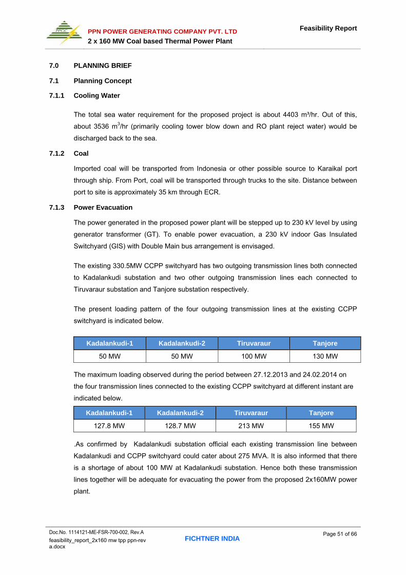
PPN POWER GENERATING COMPANY PVT. LTD
2 x 160 MW Coal based Thermal Power Plant
Feasibility Report
Doc.No. 1114121-ME-FSR-700-002, Rev.A FICHTNER INDIA
Page 51 of 66 feasibility_report_2x160 mw tpp ppn-rev a.docx
7.0 PLANNING BRIEF
7.1 Planning Concept
7.1.1 Cooling Water
The total sea water requirement for the proposed project is about 4403 m³/hr. Out of this,
about 3536 m3/hr (primarily cooling tower blow down and RO plant reject water) would be
discharged back to the sea.
7.1.2 Coal
Imported coal will be transported from Indonesia or other possible source to Karaikal port
through ship. From Port, coal will be transported through trucks to the site. Distance between
port to site is approximately 35 km through ECR.
7.1.3 Power Evacuation
The power generated in the proposed power plant will be stepped up to 230 kV level by using
generator transformer (GT). To enable power evacuation, a 230 kV indoor Gas Insulated
Switchyard (GIS) with Double Main bus arrangement is envisaged.
The existing 330.5MW CCPP switchyard has two outgoing transmission lines both connected
to Kadalankudi substation and two other outgoing transmission lines each connected to
Tiruvaraur substation and Tanjore substation respectively.
The present loading pattern of the four outgoing transmission lines at the existing CCPP
switchyard is indicated below.
Kadalankudi-1 Kadalankudi-2 Tiruvaraur Tanjore
50 MW 50 MW 100 MW 130 MW
The maximum loading observed during the period between 27.12.2013 and 24.02.2014 on
the four transmission lines connected to the existing CCPP switchyard at different instant are
indicated below.
Kadalankudi-1 Kadalankudi-2 Tiruvaraur Tanjore
127.8 MW 128.7 MW 213 MW 155 MW
.As confirmed by Kadalankudi substation official each existing transmission line between
Kadalankudi and CCPP switchyard could cater about 275 MVA. It is also informed that there
is a shortage of about 100 MW at Kadalankudi substation. Hence both these transmission
lines together will be adequate for evacuating the power from the proposed 2x160MW power
plant.

PPN POWER GENERATING COMPANY PVT. LTD
2 x 160 MW Coal based Thermal Power Plant
Feasibility Report
Doc.No. 1114121-ME-FSR-700-002, Rev.A FICHTNER INDIA
Page 52 of 66 feasibility_report_2x160 mw tpp ppn-rev a.docx
The existing transmission lines between CCPP switchyard and Kadalankudi substation
mentioned above can be connected to the proposed 230kV GIS by Line in Line out (LILO)
arrangement for evacuating the power as described above.
Generally the technical requirements and the feasibility of power evacuation will be decided
by the TNEB Ltd. The power delivery point will be firmed up based on the transmission study
by TNEB Ltd. PPN will take up with TNEB Ltd for the transmission system study and firming
up the power evacuation proposal
7.1.4 Construction Water and Power
Construction water for the proposed project will be sourced from the existing WTP and local
water authority/ Tamil Nadu Water supply and drainage Board (TWAD).
The power supply for the construction activities will be drawn from the existing CCPP at
suitable voltage level based on the feeder availability. The construction power requirement
will be about 5000 kVA.
7.2 Land use planning
The project area is already in industrial category in extent of area of 176.6-ha (436.7 Acre)
and expansion project will be developed in 40.47-ha (100 Acre) of land. The land break up
for existing and proposed plant area is furnished below.
Sl No. Description Acres Hectares
1 Existing power block 39.10 15.83
2 Existing colony 45.60 18.46
3 Green belt 162.90 65.95
4 Pond 6.50 2.63
5 Power lines and towers 39.10 15.63
6 Open land 97.90 39.63
7 Pipeline corridor, road, pump house and built area
45.60 18.46
Total 436.70 176.59
The land break up for putting up 2x160 MW proposed power plant is summarized below:
Sl No. Description Area (in acres)
1 Main Plant area 16.00
2 CHS area 6.00

PPN POWER GENERATING COMPANY PVT. LTD
2 x 160 MW Coal based Thermal Power Plant
Feasibility Report
Doc.No. 1114121-ME-FSR-700-002, Rev.A FICHTNER INDIA
Page 53 of 66 feasibility_report_2x160 mw tpp ppn-rev a.docx
Sl No. Description Area (in acres)
3 Ash dyke 20.00
4 Water Treatment System 3.50
5 Cooling water system 3
6 Buildings, roads, lay down area, construction area and miscellaneous
25.75
7 Green belt 25.75
Total 100.00
Land for Right of way
Land for the right of way for widening the existing kutcha road to connect the NH road have
been identified in the in the village of Thirukadiyur. Further work to firm up the quantum is
being taken up.
7.2.1 Layout of the Proposed Project
Layout of the expansion power plant units have been optimised considering the space
requirements for all the equipment, systems, buildings, structures, water treatment plant,
cooling water pump house etc., Adequate plant facilities will be erected for the smooth and
efficient functioning of the proposed project. The plant layout showing proposed unit is
presented in Exhibit-02.
7.3 Population Projection
The Population within 10km radial distance will be around 1,70,000. But the overall population
as per 2011 census is to be projected for exact population.

PPN POWER GENERATING COMPANY PVT. LTD
2 x 160 MW Coal based Thermal Power Plant
Feasibility Report
Doc.No. 1114121-ME-FSR-700-002, Rev.A FICHTNER INDIA
Page 54 of 66 feasibility_report_2x160 mw tpp ppn-rev a.docx
8.0 PROPOSED INFRASTRUCTURE
8.1 Industrial Area
Power block area will include heavy structures like Boilers, Turbine Generator Island,
Electrostatic precipitators, chimney, silos, Transformer yard, Control buildings, etc.
Coal handling area will include Silo, conveyer belts, junction towers, underground
hoppers, crusher house, Control rooms, etc.
Ash handling area will include Ash dyke, settling pond, water recovery pump house, etc.
Water systems will include induced draft cooling towers, forebay, water corridor with pipe
lines, pump house, DM plant, Clariflocculators, RO plant, Chemical laboratory, etc.
Apart from the above switch yard, Transmission line corridor, in plant Roads, peripheral
roads, drains, Fire protection systems, Administrative cum service buildings, Canteen,
Permanent stores, pipe lines, etc will be included.
8.2 Residential Area
The existing colony has 63 dwelling with state of art of facilities and will be expanded suitably
to meet the proposed power requirements.
8.3 Green Belt
As per the stipulations of MoEF, green belt will be provided all around the power plant
boundary by planting trees and the total green belt area including landscaping area will be
actually more than 1/3rd of the plant area.
8.4 Connectivity
The proposed site is well connected by road and rail network. The Nagapattinam-Cuddalore
(NH-45A extension) highway runs at a distance of about 2.5km from western boundary of the
project site. Thirukadayur and Tharangambadi are about 2.5km and 5.9 km west and south
directions. Nearest Railway Station is Mayiladuthurai which is at distance of 22 km from the
site.
8.5 Drinking Water Management
Treated Desalinated water will be used for potable water applications.
8.6 Sewage Treatment
Effluent from the septic tank will be routed to proposed sewage treatment plant and the
treated sewage effluent will be used for horticulture purpose
8.7 Industrial Waste Management
Waste water generated in the RO plant like filter back wash water, RO reject water, thickener
overflow and neutralized effluent from the mixed bed Ion exchange unit, CT blow down etc.,
are pumped to existing seawater return line.

PPN POWER GENERATING COMPANY PVT. LTD
2 x 160 MW Coal based Thermal Power Plant
Feasibility Report
Doc.No. 1114121-ME-FSR-700-002, Rev.A FICHTNER INDIA
Page 55 of 66 feasibility_report_2x160 mw tpp ppn-rev a.docx
8.8 Solid Waste Management
Ash is the major wastage from the power plant. Ash collected from the plant will be supplied
to various commercial users like cement industry, brick industry, road widening purpose etc.

PPN POWER GENERATING COMPANY PVT. LTD
2 x 160 MW Coal based Thermal Power Plant
Feasibility Report
Doc.No. 1114121-ME-FSR-700-002, Rev.A FICHTNER INDIA
Page 56 of 66 feasibility_report_2x160 mw tpp ppn-rev a.docx
9.0 REHABILITATION AND RESETTLEMENT (R&R ) PLAN
The proposed power project will be located adjacent to the existing plant within the existing
plant site boundary and there are no resettlements.
9.1 Project Benefit
The proposed project by PPN would enable to meet part of the growing power demand in the
Tamil Nadu due to rapid industrialization and also due to large scale use of electricity for
irrigation, domestic and commercial purposes. Further, the proposed power plant will result in
improvement of infrastructure and utilization of existing infrastructure as well as upliftment of
social structure in the area. It is anticipated that the proposed power plant will provide benefits
for the locals during construction phase as well as during operational stage.
9.2 Corporate Social Responsibility
As part of the Corporate Social Responsibility, PPN proposes to take steps in developing
education, health, infrastructure development, women empowerment, sports and vocational
training facilities. These will be taken as a part of social development of the neighboring
villages. Expenditure for CSR activities will be as per regulation of Government of India.

PPN POWER GENERATING COMPANY PVT. LTD
2 x 160 MW Coal based Thermal Power Plant
Feasibility Report
Doc.No. 1114121-ME-FSR-700-002, Rev.A FICHTNER INDIA
Page 57 of 66 feasibility_report_2x160 mw tpp ppn-rev a.docx
10.0 PROJECT SCHEDULE & COST ESTIMATES
10.1 Project Schedule
It is proposed to execute project in 28 months from date of placement of order for first unit
and 32 months for the second unit. However it is always open to improve upon the delivery,
erection schedule and commissioning, so as to bring the unit on bars as early as possible.
10.2 Method of Executing the Project
It is proposed to entrust the entire work of project execution covering the Main Plant works of
civil, electrical, instrumentation and mechanical systems to Main plant contractor, who will
take overall responsibility for timely project execution and plant performance and provide
guarantees for the same. Balance of Plant system will be executed in different packages to
match with the commissioning schedule of main plant. The scope of work of contractor will
include design, engineering, manufacture, supply, erection, testing and commissioning of
plant, equipment and facilities within the power plant area.
10.3 O&M Staff
The O&M organization will be headed by plant Manager having overall administration as well
as technical control of the power plant. Optimum level of suitable technical and administrative
personal will be placed. The total personnel foreseen for the O&M of the Plant will be about
145 peoples.
10.4 Project Cost Estimates and Cost of Generation
10.4.1 General
The project cost estimates have been worked out on the following basis.
Estimates have been prepared and presented based on market prices prevailing as
on date and based on internal data base.
Boiler price is considered for 100% imported coal.
PF technology is being considered for establishing financial report.
Cost estimate provided is based on September 2014 value and variation in cost
estimate foreseen will be +20%
10.4.2 Project Cost Estimate
Tariff estimations are based on Central Electricity Regulatory Commission (CERC) norms.
The cost estimate is preliminary one and in DPR stage detailed cost estimate will be worked
by obtaining budgetary offers from the Main Plant Equipment manufacturers.
10.4.3 Cost of Generation
The following fixed and variable costs are considered along with appropriate escalations: The fixed costs include:

PPN POWER GENERATING COMPANY PVT. LTD
2 x 160 MW Coal based Thermal Power Plant
Feasibility Report
Doc.No. 1114121-ME-FSR-700-002, Rev.A FICHTNER INDIA
Page 58 of 66 feasibility_report_2x160 mw tpp ppn-rev a.docx
a) Interest on Loan
b) Return on Equity
c) Depreciation
d) O&M expenses
e) Interest on Working Capital
f) Lime Stone cost
The variable cost covers the primary cost fuel and secondary fuel cost.
The financial analysis covering the cost of generation, revenue from sale of power,
profitability and other parameters has been carried out with the above project cost using
the CERC norms for power generation.
The salient parameters used in the analysis are;
Debt – Equity Ratio : 70: 30
Interest on Loan & Working Cap. : 12% and 12.5% p.a.
Repayment period : 11 years
Loan grace period : 1 year
Design useful life of the plant : 25 years
Normative Annual Plant Availability factor : 85%
Auxiliary Power consumption : 10.%
Plant Heat Rate : 2357 kcal/KWh
GCV of Imported Coal : 4600 kcal/kg
Cost of imported Coal : Rs.5000/MT
Quantity of secondary fuel : 0.5 ml / kWh
Cost of secondary fuel : Rs. 55 / litre
Return on equity on post tax basis : 16% p.a.
Depreciation : Straight Line Method
Operation & Maintenance cost : Rs. 28.70lakhs/ MW
Escalation on O&M : 5.72%
Discount Rate : 11.08%
It is estimated that the cost of generation works out to Rs.4.94/kWh in the first year of
operation and levelized tariff works out to Rs. 5.41 / kWh.

PPN POWER GENERATING COMPANY PVT. LTD
2 x 160 MW Coal based Thermal Power Plant
Feasibility Report
Doc.No. 1114121-ME-FSR-700-002, Rev.A FICHTNER INDIA
Page 59 of 66 feasibility_report_2x160 mw tpp ppn-rev a.docx
Parameter Unit Value
Project Cost Rs.Mio 16493.10
First year tariff
Fixed charges Rs./kWh 2.05
Energy charges Rs./kWh 2.89
Total Rs./kWh 4.94
Levelised tariff (for 25 years) Rs./kWh 5.41
DSCR 1.46
IRR Project (post tax)
% 14.55
IRR equity (post tax)
% 12.87
PPN POWER GENERATING COMPANY PVT. LTD
2 x 160 MW Coal based Thermal Power Plant
Feasibility Report
Doc.No. 1114121-ME-FSR-700-002, Rev.A FICHTNER INDIA
Page 60 of 66 feasibility_report_2x160 mw tpp ppn-rev a.docx
11.0 ANALYSIS OF PROPOSAL (FINAL RECOMMENDATIONS)
PPN has been successfully operating a 330.5 MW combined cycle power plant for nearly ten
years with high levels of availability under a PPA with TANGEDCO. Utilizing the opportunities
available under Electricity Act, 2003, PPN has proposed to set up an additional installed
capacity of 2x160 MW coal based thermal power plant as an expansion project.
With the projected future power demand scenario in India especially in the Southern India and
State of Tamil Nadu, installing a Power Plant of 2x160 MW capacity, close to Water source,
Power grid and utilizing the existing infrastructure is considered to be economically viable.
Power evacuation from the proposed power plant up to Kadalankudi substation is viable.
Further load flow from Kadalankudi to the targeted consumers needs to be established
through TNEB network.

PPN POWER GENERATING COMPANY PVT. LTD
2 x 160 MW Coal based Thermal Power Plant
Feasibility Report
Doc.No. 1114121-ME-FSR-700-002, Rev.A FICHTNER INDIA
Page 61 of 66 feasibility_report_2x160 mw tpp ppn-rev a.docx
Appendix - 1
Project Information
1.0
Owner : PPN Power Generating Company Pvt. Ltd.,
III rd Floor, Jhaver Plaza, A-1
Nungambakkam High Road,
Chennai,
Phone044-28214702,28271118
2.0 Location of the project site : Pillaiperumalnallur and Manikkapangu
Villages, Thirukkadiyur (PO),
Tharangambadi Taluk,
Nagapattinam Dist,
Tamil Nadu
3.0 Site Details
3.1 Approach to site : NH-45A East Coast Road(ECR) is just 2.5
km away
3.2 Elevation above mean sea level : 3.5 meters above mean sea level
3.3 Site Latitude and Longitude : Proposed Expansion Project Including Ash
pond1 (Inside the Plant):
F. 11 04’ 25’’ N & 79 49’ 37.00’’ E
G. 11 04’ 28’’ N & 79 49’ 54.60’’ E
H. 11 04’ 20’’ N & 79 50’ 15.35’’ E
I. 11 04’ 13’’ N & 79 50’ 09.00’’ E
J. 11 04’ 08’’ N & 79 49’ 55.00’’ E
Ash pond 2 (outside the plant)
E. 11 04’ 21.27’’ N & 79 50’ 21.36’ E
F. 11 04’ 19.16’’ N & 79 50’ 26.24 E
G. 11 04’ 21.53’’ N & 79 50’ 27.26’ E
H. 11 04’ 20.46’’ N & 79 50’ 38.18’ E
3.4 Nearest town : Tharangambadi (5.9 km)
Thirukadayur(2.5km)
3.5 Nearest Railway Station : Mayiladuthurai which is at distance of
22 km
3.6 Nearest Airport : Trichirapalli which is at distance of 150 km
3.7 Nearest Harbour : Karaikal which is at distance of 35 km
4.0 Metrological Data
4.1 Ambient Temperature
i. Minimum (Average)
ii. Maximum (Average)
:
:
20.9°C
37.9°C

PPN POWER GENERATING COMPANY PVT. LTD
2 x 160 MW Coal based Thermal Power Plant
Feasibility Report
Doc.No. 1114121-ME-FSR-700-002, Rev.A FICHTNER INDIA
Page 62 of 66 feasibility_report_2x160 mw tpp ppn-rev a.docx
iii. Design ambient for electrical equipment : 50°C
4.2 Relative Humidity
i. Maximum during monsoon (Jun to Oct)
ii. Humidity during summer (Mar to Jun)
iii. Humidity during winter (Nov to Mar)
:
:
:
85%
45 to 75%
50 to 75%
4.3 Rainfall
i. Maximum per annum
ii. Average per annum
iii. Tropical monsoon
:
:
:
1500 mm
1403 mm
June to October
4.4 Climate : Tropical, Hot, Humid
4.5 Maximum wind velocity : 47 m/s (as per IS 875, part 3)
4.6 Wind Direction Annual : W, NE, SW and SE
5.0 Seismic Data
i. Seismic Zone
ii. Horizontal seismic coefficient
iii. Vertical seismic coefficient
iv. Importance factor
:
:
:
:
II
As per latest IS : 1893
As per latest IS : 1893
1.75

PPN POWER GENERATING COMPANY PVT. LTD
2 x 160 MW Coal based Thermal Power Plant
Feasibility Report
Doc.No. 1114121-ME-FSR-700-002, Rev.A FICHTNER INDIA
Page 63 of 66 feasibility_report_2x160 mw tpp ppn-rev a.docx
Appendix - 2
Typical Ultimate Coal Analysis
Sl.No. Description Units Design Coal (Range)
1 Carbon % 40-45
2 Hydrogen % 3.67 – 3.95
3 Nitrogen % 0.87 - 0.94
4 Sulphur % 0.6 - 1
5 Oxygen % 13 – 14.5
6 Moisture % 26 – 30
7 Ash % 6 -12
8 Gross Calorific Value kcal/kg 4600 - 5100

PPN POWER GENERATING COMPANY PVT. LTD
2 x 160 MW Coal based Thermal Power Plant
Feasibility Report
Doc.No. 1114121-ME-FSR-700-002, Rev.A FICHTNER INDIA
Page 64 of 66 feasibility_report_2x160 mw tpp ppn-rev a.docx
Appendix - 3
Typical Fuel Oil Analysis
Light Distillate Oil (LDO) Data
Density at 37oC 800 kg/m³
Kinematic Viscosity at 38oC 2-7 CSt
Pour Point (Maximum) 12-18°C
Carbon by Weight Basis 0.2%
Sulphur by Weight Basis 1.0%
Water content by Weight Basis 0.05%
Ash content by Weight Basis 0.02%
Sediment by Weight Basis 1.00%
LHV 10900 kcal/kg

PPN POWER GENERATING COMPANY PVT. LTD
2 x 160 MW Coal based Thermal Power Plant
Feasibility Report
Doc.No. 1114121-ME-FSR-700-002, Rev.A FICHTNER INDIA
Page 65 of 66 feasibility_report_2x160 mw tpp ppn-rev a.docx
Appendix – 4
Seawater Analysis
S.No. Characteristics Unit Average Maximum Minimum
1 pH Value 8.08 8.30 7.80
2 Temperature oC 28.7 30.4 25.2
3 Total Suspended Solids mg/l 10.9 82 7.0
4 Total Dissolved Solids mg/l 32670 37250 27720
5 Chloride as Cl mg/l 17970 20490 15250
6 Sulphide as S mg/l 0.1 0.1 0.1
7 Sulphate SO4 mg/l 1960 2240 1660
8 Fluoride as F mg/l 1.1 1.4 0.8
9 Ammonical Nitrogen as N mg/l 0.1 0.1 0.1
10 Percent sodium mg/l 1.046 1.192 0.887
11 Copper as Cu mg/l < 0.01 < 0.01 < 0.01
12 Zinc as Zn mg/l 0.7 0.8 0.1
13 Phenolic Compounds as (C6H5OH)
mg/l < 0.001 < 0.001 < 0.001
14 Oil and Grease mg/l < 5 < 5 < 5
15 Boron as B mg/l - - -
16 BOD 5 days at 20 oC mg/l 12 24 8
17 COD mg/l 26 80 15
18 Total Residual Chlorine mg/l Nil Nil Nil
19 Arsenic as As mg/l < 0.01 < 0.01 < 0.01
20 Cadmium as Cd mg/l < 0.01 < 0.01 < 0.01
21 Total chromium as Cr mg/l < 0.01 < 0.01 < 0.01
22 Chromium as (Hexavalent Cr+6)
mg/l < 0.01 < 0.01 < 0.01
23 Lead as Pb mg/l < 0.01 < 0.01 < 0.01
24 Selenium as Se mg/l < 0.01 < 0.01 < 0.01
25 Mercury as Hg mg/l < 0.01 < 0.01 < 0.01
26 Pesticides mg/l Absent Absent Absent
27 Alpha Emitters Micro
Curie/ml - - -

PPN POWER GENERATING COMPANY PVT. LTD
2 x 160 MW Coal based Thermal Power Plant
Feasibility Report
Doc.No. 1114121-ME-FSR-700-002, Rev.A FICHTNER INDIA
Page 66 of 66 feasibility_report_2x160 mw tpp ppn-rev a.docx
S.No. Characteristics Unit Average Maximum Minimum
28 Beta Emitters Micro
Curie/ml - - -
29 Free Ammonia as NH3 mg/l Absent Absent Absent
30 Dissolved Phosphates as P mg/l 0.6 0.8 0.2
31 Total Kjeldahl Nitrogen as N mg/l 1.5 2.0 0.8
32 Cyanide as CN mg/l Absent Absent Absent
33 Nickel as Ni mg/l < 0.01 < 0.01 < 0.01
34 Residual Sodium Carbonate mg/l - - -
35 Reactive silica Ppm 10 10 10