Embed Size (px)
Citation preview
FE electronic box
• Construction of end piece OT module
• Electronic components
• Mechanics
• Cooling

End-piece Feed trough boards at dummy

End piece
• The OT module exists out of two identical panels holding 64 straws.
• 2 Feed trough boards connecting HV and gnd over full width to outside world

End-piece construction
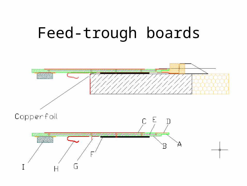
Feed-trough boards

Electronic components
• Overview of boards
• Full or half module
• Stacking of boards
• HV and connector section

Electronic components
• Feed-trough board 2x• HV-board 4x• ASD-board 8x• OTIS-board 4x• GOL-board 1x

Full or half module
GOL/OTIS board design is made in such a manner that it can switch from left to right

Stacking of boards
• 2 planes of 64 channels• 32 channel HV-boards• Each HV-board connects
2 ASD-boards• 2 ASD-boards connect L
or R OTIS • OTIS-board L and R
version• GOL-board connects 4
OTIS-boards front and back plane

HV connector-section
• 4 HV-boards make an enclosure so HV is completely shielded from other electronic parts
• HV space contains 4 boards carrying 32 cap each that are integrated in the board
• HV-distribution inside
• One side HV is coming in other side is low voltage and couples to ASD board trough frame plate.

Disconnected FE-box
• Fast replacement• FE-box is fully
decoupled from chamber

Connected FE-box
• full HV-enclosure• Forces from gnd-
spring are not on chamber
• Gnd spring over full width
• 128 gnd contacts on each side
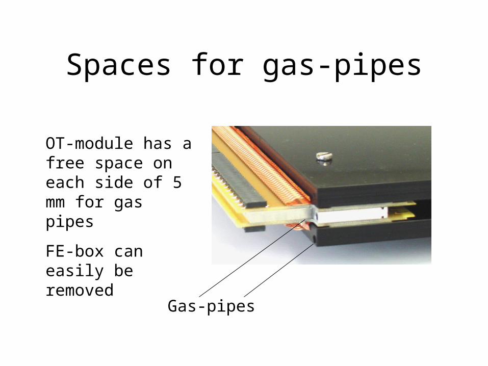
Spaces for gas-pipes
Gas-pipes
OT-module has a free space on each side of 5 mm for gas pipes
FE-box can easily be removed

FE box overview
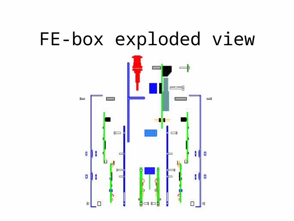
FE-box exploded view
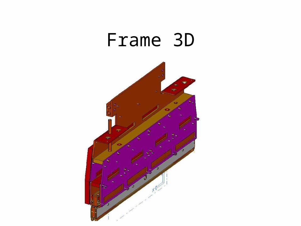
Frame 3D

main mechanic parts
• One plate supports gol/aux boards
• 2 equal support plates on both sides, supporting HV-boards, ASD boards and Otis board.
• 2 extraction/insertion tools are implemented
• Guiding tip guarantees proper mating with chamber connector
A
C
B
D
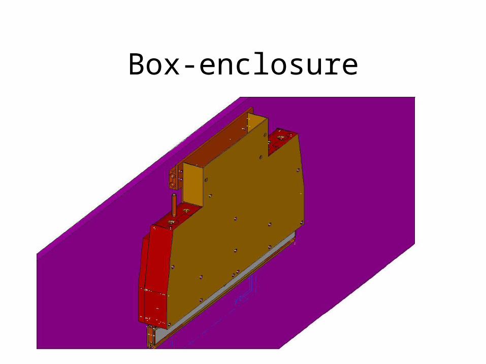
Box-enclosure

Cooling
• Location of dissipating areas • Heat transport trough the frame• Heat transport from chips to frame• measurements

Dissipating areas
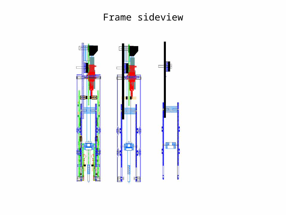
Frame sideview

ASDBLR COOLING CONSTRUCTION
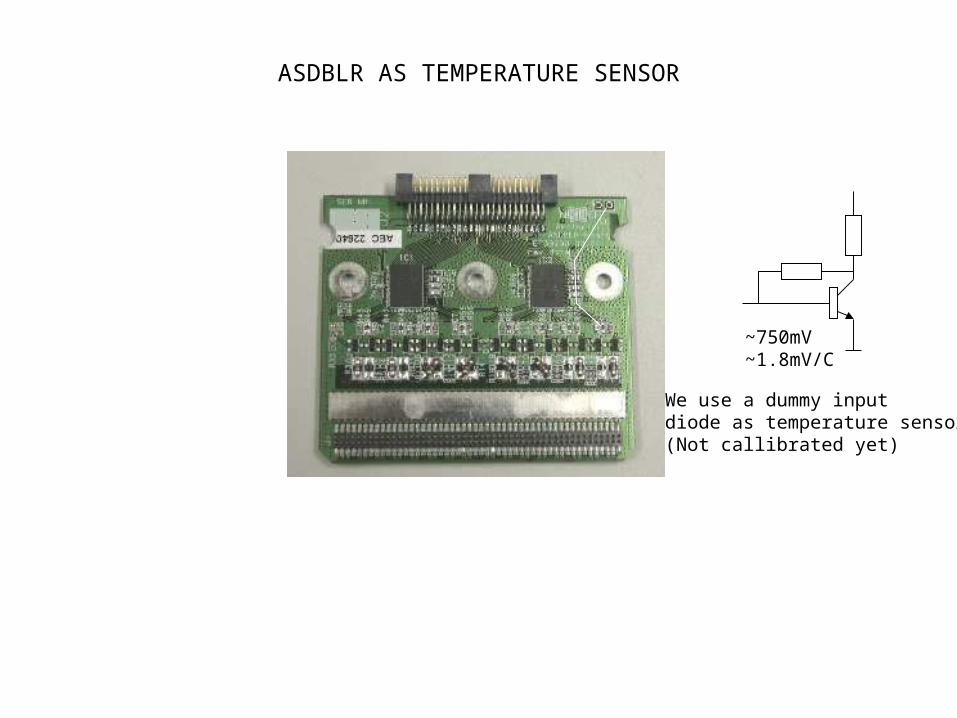
ASDBLR AS TEMPERATURE SENSOR
~750mV~1.8mV/C
We use a dummy inputdiode as temperature sensor(Not callibrated yet)

NTC 5K on Copper Surface Close to ASDBLR
Each board has a sensorConnection point

OTIS NTC
NTC UNDER OTIS ON OPOSITE SIDE

PACKAGED FRONT END COOLING TEST
The Front Ends of the Outer Tracker are closely packed, heat must be extracted with cooling wateralong the Aluminium cooling extension plate. For the test we use a cooling block with forced airSeveral sensors monitor heatup of components.

Proto Outer Tracker Front-End Tests
27EFNI HK
35 C
Otis52 C
ASDBLR NTC on copper 42C
ASDBLRInput Diode43C
RESULTS AFTER SETTLING

NTC GRAPH
K ohm
temp

25
50
30
35
40
45
12 Hours
COOLING BASE
6321
RED ASDBLR NTC ON Copper Board SURFACE 42C
BASEPLATE THERMOMETER 35C
t=0 >power on
REMARKS:1.forced air cooling base with regulators, shifts 10C2.ASDBLR steps up 5C in 2 minutes, then settles to 7C above plate3. OTIS settles 17C above cooling flap part of baseplate
OTIS Copper NTC 52C
BLUE ASDBLR DIODE ~43CASDBLR
17C
8C
FIRST IMPRESSION FROM PAPER RECORDERS AFTER POWER SWITCH ON

FIRST CONCLUSIONS
The ASDBLR has low temperature rise thanks to strong thermal coupling trough PCB Delta T=7 degrees C
The maximum delta T is 17 degrees C for the Otis chip
The regulators are mounted directly on the cooling plate , no internal sensor available, but adequate cooling is ok.


![· Web viewsyndrome*[ot] OR motor development disorder*[ot] OR Stereotypic Movement Disorder*[ot] OR Body Rocking[ot] OR Body-Focused Repetitive Behavio*[ot] OR Head Banging[ot]](https://img.dokumen.tips/doc/110x75/5b0593dc7f8b9ad1768b921d/viewsyndromeot-or-motor-development-disorderot-or-stereotypic-movement-disorderot.jpg)