Embed Size (px)
Citation preview

Report No.: 90709001-D
Page 1 / 21
FCC DoC TEST REPORT
for
22” Panel PC
MODEL: W22IA7T-CHA2; W22IXXX-XXXXXX
Test Report Number: 90709001-D
Issued to:
Winmate Communication INC. 9F, No. 111-6, Shing-De Rd., San-Chung City,
Taipei 241, Taiwan, R.O.C.
Issued by:
Compliance Certification Services Inc.
Sindian BU.
No.163-1, Jhongsheng Rd., Sindian City, Taipei County 23151, Taiwan
TEL: 886-2-22170894
FAX: 886-2-22171029
Issued Date: July 17, 2009
Note: This report shall not be reproduced except in full, without the written approval of Compliance Certification Services Inc. This document may be altered or revised by Compliance Certification Services Inc. personnel only, and shall be noted in the revision section of the document. The client should not use it to claim product endorsement by TAF, A2LA, NVLAP, NIST or any government agencies. The test results in the report only apply to the tested sample.

Report No.: 90709001-D
Page 2 This report shall not be reproduced except in full, without the written approval of Compliance Certification Services.
Revision History
Rev. Issue Date
Revisions
Effect Page
Revised By
00 July 17, 2009 Initial Issue ALL Joy hsiao

Report No.: 90709001-D
Page 3 This report shall not be reproduced except in full, without the written approval of Compliance Certification Services.
TABLE OF CONTENTS
1 TEST RESULT CERTIFICATION ................................................................................................4 2 EUT DESCRIPTION ........................................................................................................................5 3 TEST METHODOLOGY.................................................................................................................6
3.1. DECISION OF FINAL TEST MODE ............................................................................................................... 6 3.2. EUT SYSTEM OPERATION............................................................................................................................ 6
4 SETUP OF EQUIPMENT UNDER TEST......................................................................................7 4.1. DESCRIPTION OF SUPPORT UNITS............................................................................................................. 7 4.2. CONFIGURATION OF SYSTEM UNDER TEST ........................................................................................... 8
5 FACILITIES AND ACCREDITATIONS.......................................................................................9 5.1. FACILITIES....................................................................................................................................................... 9 5.2. ACCREDITATIONS ......................................................................................................................................... 9 5.3. MEASUREMENT UNCERTAINTY ................................................................................................................ 9
6 CONDUCTED EMISSION MEASUREMENT ...........................................................................10 6.1. LIMITS OF CONDUCTED EMISSION MEASUREMENT .......................................................................... 10 6.2. TEST INSTRUMENTS ................................................................................................................................... 10 6.3. TEST PROCEDURES ..................................................................................................................................... 11 6.4. TEST SETUP ................................................................................................................................................... 12 6.5. DATA SAMPLE .............................................................................................................................................. 12 6.6. TEST RESULTS .............................................................................................................................................. 13
7 RADIATED EMISSION MEASUREMENT................................................................................14 7.1. LIMITS OF RADIATED EMISSION MEASUREMENT .............................................................................. 14 7.2. TEST INSTRUMENTS ................................................................................................................................... 14 7.3. TEST PROCEDURES ..................................................................................................................................... 15 7.4. TEST SETUP ................................................................................................................................................... 16 7.5. DATA SAMPLE .............................................................................................................................................. 17 7.6. TEST RESULTS .............................................................................................................................................. 18
8 PHOTOGRAPHS OF THE TEST CONFIGURATION .............................................................20

Report No.: 90709001-D
Page 4 This report shall not be reproduced except in full, without the written approval of Compliance Certification Services.
1 TEST RESULT CERTIFICATION
Product: 22” Panel PC
Model: W22IA7T-CHA2; W22IXXX-XXXXXX (X=A~Z , a~z , 0 ~9 , Blank or Slash)
Brand: Winmate
Applicant: Winmate Communication INC. 9F, No. 111-6, Shing-De Rd., San-Chung City, Taipei 241, Taiwan, R.O.C.
Manufacturer: Winmate Communication INC. 9F, No. 111-6, Shing-De Rd., San-Chung City, Taipei 241, Taiwan, R.O.C.
Tested: July 13, 2009 & July 14, 2009
EMISSION Standard Item Result Remarks
Conducted (Main Port) PASS Meet Class B limit FCC 47 CFR Part 15 Subpart B, ICES-003 Issue 4 ANSI C63.4-2003 Radiated PASS Meet Class B limit
Note: 1. The statements of test result on the above are decided by the request of test standard only; the measurement
uncertainties are not factored into this compliance determination. 2. The information of measurement uncertainty is available upon the customer’s request.
Deviation from Applicable Standard
None The above equipment has been tested by Compliance Certification Services Inc., and found compliance with the requirements set forth in the technical standards mentioned above. The results of testing in this report apply only to the product/system, which was tested. Other similar equipment will not necessarily produce the same results due to production tolerance and measurement uncertainties.

Report No.: 90709001-D
Page 5 This report shall not be reproduced except in full, without the written approval of Compliance Certification Services.
2 EUT DESCRIPTION
Product 22” Panel PC
Brand Name Winmate
Model W22IA7T-CHA2; W22IXXX-XXXXXX (X=A~Z , a~z , 0 ~9 , Blank or Slash)
Applicant Winmate Communication INC.
Housing material Metal case
Identify Number 90709001
Received Date July 09, 2009
EUT Power Rating 12VDC from AC Adaptor
AC Power During Test 120VAC / 60Hz to AC Adaptor
AC Adaptor Manufacturer EDAC
AC Adaptor Model Number EA11801A-120
Power Adaptor Power Rating I/P: 100-240VAC~3.0A, 50-60Hz O/P: 12VDC 12.5A
AC Power Cord Type Unshielded, 1.8m (Detachable) to AC Adaptor
DC Power Cable Type Unshielded, 1.0m (Non-detachable, with a core) to AC Adaptor
I/O PORT
I/O PORT TYPES Q’TY TESTED WITH
1) SIO Port 3 3
2) PS/2 Keyboard Port 1 1
3) PS/2 Mouse Port 1 1
4) VGA Port 1 1
5) Audio In Port 1 1
6) Microphone Port 1 1
7) Earphone Port 1 1
8) USB Port 4 4
9) LAN Port 2 2
Note: Client consigns only one model sample to test (Model Number: W22IA7T-CHA2).

Report No.: 90709001-D
Page 6 This report shall not be reproduced except in full, without the written approval of Compliance Certification Services.
3 TEST METHODOLOGY
3.1. DECISION OF FINAL TEST MODE
The EUT was tested together with the above additional components, and a configuration, which produced the worst emission levels, was selected and recorded in this report.
The test configuration/ mode is as the following: Conduction Modes:
1. 2048X1536, VF=60Hz / D-SUB ONLY MODE 2. 1600X1200, VF=60Hz / D-SUB ONLY MODE 3. 1366X768, VF=60Hz / EUT + D-SUB MODE 4. 800X600, VF=60Hz / EUT + D-SUB MODE
Radiation Modes:
1. 2048X1536, VF=60Hz / D-SUB ONLY MODE 2. 1600X1200, VF=60Hz / D-SUB ONLY MODE
1366X768, VF=60Hz / EUT + D-SUB MODE 3. 1366X768, VF=60Hz / EUT + D-SUB MODE / 1-8GHz
4. 800X600, VF=60Hz / EUT + D-SUB MODE Conduction: Mode 3 Radiation: Mode 3
3.2. EUT SYSTEM OPERATION
1. Windows XP boots system.
2. Run MyHwin.exe to activate all peripherals and display “H” pattern on monitor screen.
3. Run Winemc.exe and choose media player to play music.
4. Run Wimemc.exe and choose “E:/ & F:/ & G:/ & H:/” to test EUT.
5. Press the start menu, select executive and type ping 192.168.0.1&2 –t (EUT), ping 192.168.0.3&4 –t (Server Notebook).
Note: Test program is self-repeating throughout the test.

Report No.: 90709001-D
Page 7 This report shall not be reproduced except in full, without the written approval of Compliance Certification Services.
4 SETUP OF EQUIPMENT UNDER TEST
4.1. DESCRIPTION OF SUPPORT UNITS
The EUT has been tested as an independent unit together with other necessary accessories or support units. The following support units or accessories were used to form a representative test configuration during the tests. EUT Devices:
No. Equipment Model No. Trade Name
1. Mother Board IA70 Winmate
2. Panel LCD T216XW01-V0 AUO
3. RAM (1GB) N/A Transcend
4. HDD (80GB) 800AAJS WD
5. CPU (1.60GHz) Intel_Atom_1.60GHz Intel
Peripherals Devices:
No. Equipment Model No. Serial No. FCC ID / BSMI ID Trade Name Data Cable Power Cord
1. USB 2.0 HDD F12-UF N/A BSMI ID: 4912A002 TeraSys Shielded, 1.8m N/A
2. USB 2.0 HDD F12-UF N/A BSMI ID: 4912A002 TeraSys Shielded, 1.8m N/A
3. USB 2.0 HDD F12-UF N/A BSMI ID: 4912A002 TeraSys Shielded, 1.8m N/A
4. USB 2.0 HDD F12-UF N/A BSMI ID: 4912A002 TeraSys Shielded, 1.8m N/A
5. PS/2 Mouse M071KC 443029438 DoC BSMI: R41108 DELL Shielded, 1.8m N/A
6. PS/2 Keyboard SK-8110 N/A DoC BSMI: T3A002 DELL Shielded, 1.8m N/A
7. Player RQ-L11LT N/A BSMI ID: 3912A162 Panasonic Unshielded, 1.8m N/A
8. Earphone & Microphone MSB301 N/A N/A e-Sense Unshielded, 1.8m N/A
9. Monitor 202P40 BZ000405640006 FCC ID: A3KM107 BSMI: R33048 PHILIPS Shielded, 1.8m
with two cores Unshielded, 1.8m
10. Modem 5JEG4033MKO N/A 5RJTAI-35500-M5-E TOP- SOLUTION Shielded, 1.8m Unshielded, 1.8m
11. Modem 5JEG4033MKO N/A 5RJTAI-35500-M5-E TOP- SOLUTION Shielded, 1.8m Unshielded, 1.8m
12. Modem 5JEG4033MKO N/A 5RJTAI-35500-M5-E TOP- SOLUTION Shielded, 1.8m Unshielded, 1.8m
13. Server Notebook 1 2210B CNV7472KG5 DoC
BSMI: R33001 HP Unshielded, 20m Unshielded, 1.8m
14 Server Notebook 2 2210B CNV7472KDP DoC
BSMI: R33001 HP Unshielded, 20m Unshielded, 1.8m
Note: 1) All the equipment/cables were placed in the worst-case configuration to maximize the emission during the test. 2) Grounding was established in accordance with the manufacturer’s requirements and conditions for the intended
use.

Report No.: 90709001-D
Page 8 This report shall not be reproduced except in full, without the written approval of Compliance Certification Services.
4.2. CONFIGURATION OF SYSTEM UNDER TEST
USB 2.0 HDD X4
PS/2 Mouse
PS/2 Keyboard Player Earphone &
Microphone
Monitor EUT Modem X3 Server Notebook X2
Adaptor(EUT)

Report No.: 90709001-D
Page 9 This report shall not be reproduced except in full, without the written approval of Compliance Certification Services.
5 FACILITIES AND ACCREDITATIONS
5.1. FACILITIES All measurement facilities used to collect the measurement data are located at CCS Taiwan Sindian BU. at No.163-1, Jhongsheng Rd., Sindian City, Taipei County 23151, Taiwan. The sites are constructed in conformance with the requirements of ANSI C63.4 and CISPR Publication 22. All receiving equipment conforms to CISPR 16-1-1, CISPR 16-1-2, CISPR 16-1-3, CISPR 16-1-4 and CISPR 16-1-5.
5.2. ACCREDITATIONS Our laboratories are accredited and approved by the following accreditation body according to ISO/IEC 17025.
Taiwan TAF USA A2LA
The measuring facility of laboratories has been authorized or registered by the following approval agencies.
Canada Industry Canada Germany TUV Rheinland Japan VCCI Taiwan BSMI USA FCC
Copies of granted accreditation certificates are available for downloading from our web site, http://www.ccsemc.com
5.3. MEASUREMENT UNCERTAINTY Where relevant, the following measurement uncertainty levels have been estimated for tests performed on the EUT as specified in CISPR 16-4-2:
Measurement Frequency Uncertainty
Conducted emissions 0.15MHz ~ 30MHz ± 1.7376
30MHz ~ 200MHz ± 3.8710 Radiated emissions
200MHz ~ 1000MHz ± 3.8712 This uncertainty represents an expanded uncertainty expressed at approximately the 95% confidence level using a coverage factor of k=2.
Consistent with industry standard (e.g. CISPR 22: 2006, clause 11, Measurement Uncertainty) determining compliance with the limits shall be base on the results of the compliance measurement. Consequently the measure emissions being less than the maximum allowed emission result in this be a compliant test or passing test.
The acceptable measurement uncertainty value without requiring revision of the compliance statement is base on conducted and radiated emissions being less than UCISPR which is 3.6dB and 5.2dB respectively. CCS values (called ULab in CISPR 16-4-2) is less than UCISPR as shown in the table above. Therefore, MU need not be considered for compliance.
Report No.: 90709001-D
Page 10 This report shall not be reproduced except in full, without the written approval of Compliance Certification Services.
6 CONDUCTED EMISSION MEASUREMENT
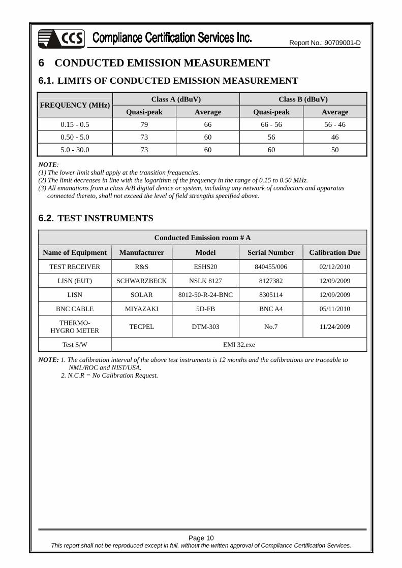
6.1. LIMITS OF CONDUCTED EMISSION MEASUREMENT
Class A (dBuV) Class B (dBuV) FREQUENCY (MHz)
Quasi-peak Average Quasi-peak Average
0.15 - 0.5 79 66 66 - 56 56 - 46
0.50 - 5.0 73 60 56 46
5.0 - 30.0 73 60 60 50
NOTE: (1) The lower limit shall apply at the transition frequencies. (2) The limit decreases in line with the logarithm of the frequency in the range of 0.15 to 0.50 MHz. (3) All emanations from a class A/B digital device or system, including any network of conductors and apparatus connected thereto, shall not exceed the level of field strengths specified above.
6.2. TEST INSTRUMENTS
Conducted Emission room # A
Name of Equipment Manufacturer Model Serial Number Calibration Due
TEST RECEIVER R&S ESHS20 840455/006 02/12/2010
LISN (EUT) SCHWARZBECK NSLK 8127 8127382 12/09/2009
LISN SOLAR 8012-50-R-24-BNC 8305114 12/09/2009
BNC CABLE MIYAZAKI 5D-FB BNC A4 05/11/2010
THERMO- HYGRO METER TECPEL DTM-303 No.7 11/24/2009
Test S/W EMI 32.exe
NOTE: 1. The calibration interval of the above test instruments is 12 months and the calibrations are traceable to NML/ROC and NIST/USA.
2. N.C.R = No Calibration Request.

Report No.: 90709001-D
Page 11 This report shall not be reproduced except in full, without the written approval of Compliance Certification Services.
6.3. TEST PROCEDURES (please refer to measurement standard or CCS SOP PA-031)
Procedure of Preliminary Test
! The EUT and Support equipment, if needed, was set up as per the test configuration to simulate typical usage per the user’s manual. When the EUT is a tabletop system, a wooden table with a height of 0.8 meters is used and is placed on the ground plane as per ANSI C63.4 (see Test Facility for the dimensions of the ground plane used). When the EUT is a floor standing equipment, it is placed on the ground plane, which has a 12 mm non-conductive covering to insulate the EUT from the ground plane.
! All I/O cables were positioned to simulate typical actual usage as per ANSI C63.4.
! The test equipment EUT installed received AC main power, through a Line Impedance Stabilization Network (LISN), which supplied power source and was grounded to the ground plane.
! All support equipment power received from a second LISN.
! The EUT test program was started. Emissions were measured on each current carrying line of the EUT using an EMI Test Receiver connected to the LISN powering the EUT.
! The Receiver scanned from 150kHz to 30MHz for emissions in each of the test modes.
! During the above scans, the emissions were maximized by cable manipulation.
! The test mode(s) described in Item 3.1 were scanned during the preliminary test.
! After the preliminary scan, we found the test mode described in Item 3.1 producing the highest emission level.
! The EUT configuration and cable configuration of the above highest emission levels were recorded for reference of the final test.
Procedure of Final Test
! EUT and support equipment were set up on the test bench as per the configuration with highest emission level in the preliminary test.
! A scan was taken on both power lines, Line 1 and Line 2, recording at least the six highest emissions. Emission frequency and amplitude were recorded into a computer in which correction factors were used to calculate the emission level and compare reading to the applicable limit.
! The test data of the worst-case condition(s) was recorded.

Report No.: 90709001-D
Page 12 This report shall not be reproduced except in full, without the written approval of Compliance Certification Services.
6.4. TEST SETUP
! For the actual test configuration, please refer to the related item – Photographs of the Test Configuration.
6.5. DATA SAMPLE
Freq. (MHz)
Read Level
(dBuV)
Factor (dB)
Level (dBuV)
Limit Line
(dBuV)
Over Limit (dB)
Remark (P/Q/A)
Line (L1/L2)
x.xx 42.95 0.55 43.50 56 -12.50 Q L1
Freq. = Emission frequency in MHz Read Level = Uncorrected Analyzer/Receiver reading Factor = Insertion loss of LISN + Cable Loss Level = Read Level + Factor Limit Line = Limit stated in standard Over Limit = Reading in reference to limit P = Peak Reading Q = Quasi-peak Reading A = Average Reading L1 = Hot side L2 = Neutral side Calculation Formula
Over Limit (dB) = Level (dBuV) – Limit Line (dBuV)
EUT
LISN
EMI receiver
Reference ground plane
Vert. reference plane
40cm
80cm

Report No.: 90709001-D
Page 13 This report shall not be reproduced except in full, without the written approval of Compliance Certification Services.
6.6. TEST RESULTS
Model No. W22IA7T-CHA2 6dB Bandwidth 10 KHz
Environmental Conditions 25°C, 70% RH, 1010mbar Test Mode Mode 3
Tested by Brian Chen
(The chart below shows the highest readings taken from the final data.)
Six Highest Conducted Emission Readings Frequency Range Investigated 150 KHz to 30 MHz
Freq. (MHz)
Read Level
(dBuV)
Factor (dB)
Level (dBuV)
Limit Line
(dBuV)
Over Limit (dB)
Remark (P/Q/A)
Line (L1/L2)
0.469 44.00 0.07 44.07 56.54 -12.47 P L1 0.654 43.86 0.09 43.95 56.00 -12.05 P L1 0.839 44.40 0.10 44.50 56.00 -11.50 P L1 0.654 43.50 0.09 43.59 56.00 -12.41 P L2 0.839 44.82 0.10 44.92 56.00 -11.08 P L2 1.037 44.52 0.11 44.63 56.00 -11.37 P L2
NOTE: 1. L1 = Line One (Live Line) / L2 = Line Two (Neutral Line).
2. The emission level was or more than 2dB below the Average limit, so no re-check anymore.
Report No.: 90709001-D
Page 14 This report shall not be reproduced except in full, without the written approval of Compliance Certification Services.
7 RADIATED EMISSION MEASUREMENT
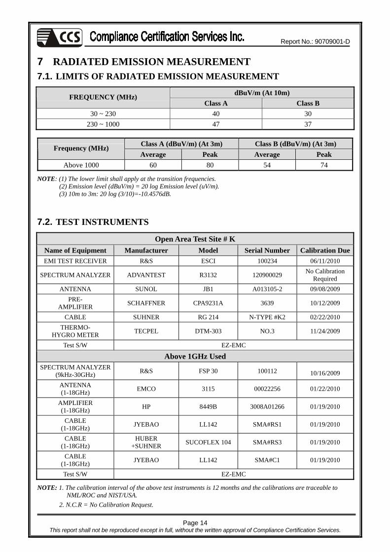
7.1. LIMITS OF RADIATED EMISSION MEASUREMENT
dBuV/m (At 10m) FREQUENCY (MHz) Class A Class B
30 ~ 230 40 30 230 ~ 1000 47 37
Class A (dBuV/m) (At 3m) Class B (dBuV/m) (At 3m) Frequency (MHz) Average Peak Average Peak
Above 1000 60 80 54 74
NOTE: (1) The lower limit shall apply at the transition frequencies. (2) Emission level (dBuV/m) = 20 log Emission level (uV/m). (3) 10m to 3m: 20 log (3/10)=-10.4576dB. 7.2. TEST INSTRUMENTS
Open Area Test Site # K Name of Equipment Manufacturer Model Serial Number Calibration DueEMI TEST RECEIVER R&S ESCI 100234 06/11/2010
SPECTRUM ANALYZER ADVANTEST R3132 120900029 No Calibration Required
ANTENNA SUNOL JB1 A013105-2 09/08/2009 PRE-
AMPLIFIER SCHAFFNER CPA9231A 3639 10/12/2009
CABLE SUHNER RG 214 N-TYPE #K2 02/22/2010 THERMO-
HYGRO METER TECPEL DTM-303 NO.3 11/24/2009
Test S/W EZ-EMC
Above 1GHz Used SPECTRUM ANALYZER
(9kHz-30GHz) R&S FSP 30 100112 10/16/2009
ANTENNA (1-18GHz) EMCO 3115 00022256 01/22/2010
AMPLIFIER (1-18GHz) HP 8449B 3008A01266 01/19/2010
CABLE (1-18GHz) JYEBAO LL142 SMA#RS1 01/19/2010
CABLE (1-18GHz)
HUBER +SUHNER SUCOFLEX 104 SMA#RS3 01/19/2010
CABLE (1-18GHz) JYEBAO LL142 SMA#C1 01/19/2010
Test S/W EZ-EMC
NOTE: 1. The calibration interval of the above test instruments is 12 months and the calibrations are traceable to NML/ROC and NIST/USA.
2. N.C.R = No Calibration Request.

Report No.: 90709001-D
Page 15 This report shall not be reproduced except in full, without the written approval of Compliance Certification Services.
7.3. TEST PROCEDURES (please refer to measurement standard or CCS SOP PA-031)
Procedure of Preliminary Test
! The equipment was set up as per the test configuration to simulate typical usage per the user’s manual. When the EUT is a tabletop system, a wooden turntable with a height of 0.8 meters is used which is placed on the ground plane. When the EUT is a floor standing equipment, it is placed on the ground plane which has a 12 mm non-conductive covering to insulate the EUT from the ground plane.
! Support equipment, if needed, was placed as per ANSI C63.4.
! All I/O cables were positioned to simulate typical usage as per ANSI C63.4.
! The EUT received AC power source from the outlet socket under the turntable. All support equipment power received from another socket under the turntable.
! The antenna was placed at 10/ 3 meter away from the EUT as stated in ANSI C63.4. The antenna connected to the Spectrum Analyzer via a cable and at times a pre-amplifier would be used.
! The Analyzer / Receiver quickly scanned from 30MHz to 8000MHz. The EUT test program was started. Emissions were scanned and measured rotating the EUT to 360 degrees and positioning the antenna 1 to 4 meters above the ground plane, in both the vertical and the horizontal polarization, to maximize the emission reading level.
! The test mode(s) described in Item 3.1 were scanned during the preliminary test:
! After the preliminary scan, we found the test mode described in Item 3.1 producing the highest emission level.
! The EUT and cable configuration, antenna position, polarization and turntable position of the above highest emission level were recorded for the final test.

Report No.: 90709001-D
Page 16 This report shall not be reproduced except in full, without the written approval of Compliance Certification Services.
Filter Filter Filter To Power
EUT
Ground Plane10 m / 3 m
0.8 m
Coaxial Cable
Test table & Turntable
1m or 1m ~ 4m
Power Cable
EMI Receiver
Filter
Procedure of Final Test
! EUT and support equipment were set up on the turntable as per the configuration with highest emission level in the preliminary test.
! The Analyzer / Receiver scanned from 30MHz to 8000MHz. Emissions were scanned and measured rotating the EUT to 360 degrees, varying cable placement and positioning the antenna 1 to 4 meters above the ground plane, in both the vertical and the horizontal polarization, to maximize the emission reading level.
! Recorded at least the six highest emissions. Emission frequency, amplitude, antenna position, polarization and turntable position were recorded into a computer in which correction factors were used to calculate the emission level and compare reading to the applicable limit and only Q.P. reading is presented.
! The test data of the worst-case condition(s) was recorded.
7.4. TEST SETUP
! For the actual test configuration, please refer to the related item – Photographs of the Test
Configuration.
Report No.: 90709001-D
Page 17 This report shall not be reproduced except in full, without the written approval of Compliance Certification Services.
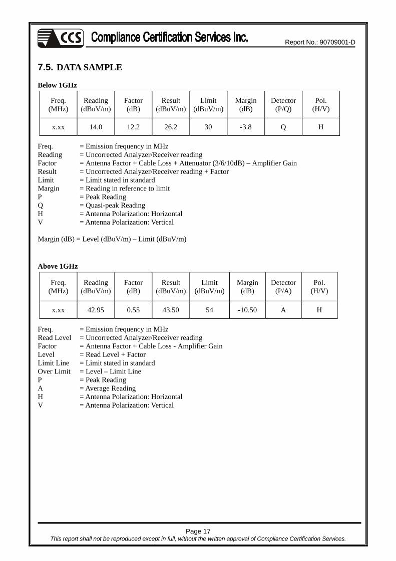
7.5. DATA SAMPLE
Below 1GHz
Freq. (MHz)
Reading (dBuV/m)
Factor (dB)
Result (dBuV/m)
Limit (dBuV/m)
Margin (dB)
Detector (P/Q)
Pol. (H/V)
x.xx 14.0 12.2 26.2 30 -3.8 Q H
Freq. = Emission frequency in MHz Reading = Uncorrected Analyzer/Receiver reading Factor = Antenna Factor + Cable Loss + Attenuator (3/6/10dB) – Amplifier Gain Result = Uncorrected Analyzer/Receiver reading + Factor Limit = Limit stated in standard Margin = Reading in reference to limit P = Peak Reading Q = Quasi-peak Reading H = Antenna Polarization: Horizontal V = Antenna Polarization: Vertical Margin (dB) = Level (dBuV/m) – Limit (dBuV/m) Above 1GHz
Freq. (MHz)
Reading (dBuV/m)
Factor (dB)
Result (dBuV/m)
Limit (dBuV/m)
Margin (dB)
Detector (P/A)
Pol. (H/V)
x.xx 42.95 0.55 43.50 54 -10.50 A H
Freq. = Emission frequency in MHz Read Level = Uncorrected Analyzer/Receiver reading Factor = Antenna Factor + Cable Loss - Amplifier Gain Level = Read Level + Factor Limit Line = Limit stated in standard Over Limit = Level – Limit Line P = Peak Reading A = Average Reading H = Antenna Polarization: Horizontal V = Antenna Polarization: Vertical
Report No.: 90709001-D
Page 18 This report shall not be reproduced except in full, without the written approval of Compliance Certification Services.
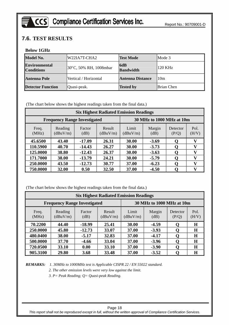
7.6. TEST RESULTS
Below 1GHz Model No. W22IA7T-CHA2 Test Mode Mode 3
Environmental Conditions 30°C, 50% RH, 1008mbar 6dB
Bandwidth 120 KHz
Antenna Pole Vertical / Horizontal Antenna Distance 10m
Detector Function Quasi-peak. Tested by Brian Chen
(The chart below shows the highest readings taken from the final data.)
Six Highest Radiated Emission Readings Frequency Range Investigated 30 MHz to 1000 MHz at 10m
Freq. (MHz)
Reading (dBuV/m)
Factor (dB)
Result (dBuV/m)
Limit (dBuV/m)
Margin (dB)
Detector (P/Q)
Pol. (H/V)
45.6500 43.40 -17.09 26.31 30.00 -3.69 Q V 110.5900 40.70 -14.43 26.27 30.00 -3.73 Q V 125.0000 38.80 -12.43 26.37 30.00 -3.63 Q V 171.7000 38.00 -13.79 24.21 30.00 -5.79 Q V 250.0000 43.50 -12.73 30.77 37.00 -6.23 Q V 750.0000 32.00 0.50 32.50 37.00 -4.50 Q V
(The chart below shows the highest readings taken from the final data.)
Six Highest Radiated Emission Readings Frequency Range Investigated 30 MHz to 1000 MHz at 10m
Freq. (MHz)
Reading (dBuV/m)
Factor (dB)
Result (dBuV/m)
Limit (dBuV/m)
Margin (dB)
Detector (P/Q)
Pol. (H/V)
70.2200 44.40 -18.99 25.41 30.00 -4.59 Q H 250.0000 45.80 -12.73 33.07 37.00 -3.93 Q H 480.0400 38.00 -5.17 32.83 37.00 -4.17 Q H 500.0000 37.70 -4.66 33.04 37.00 -3.96 Q H 720.0500 33.10 0.00 33.10 37.00 -3.90 Q H 905.3100 29.80 3.68 33.48 37.00 -3.52 Q H
REMARKS: 1. 30MHz to 1000MHz test is Applicable CISPR 22 / EN 55022 standard.
2. The other emission levels were very low against the limit. 3. P= Peak Reading; Q= Quasi-peak Reading.

Report No.: 90709001-D
Page 19 This report shall not be reproduced except in full, without the written approval of Compliance Certification Services.
Above 1GHz Model No. W22IA7T-CHA2 Test Mode Mode 3
Environmental Conditions 26°C, 60% RH, 1010mbar 6dB
Bandwidth 1000 KHz
Antenna Pole Vertical / Horizontal Antenna Distance 3m
Detector Function Peak or Average. Tested by Brian Chen
(The chart below shows the highest readings taken from the final data.)
Highest Radiated Emission Readings Frequency Range Investigated 1000 MHz to 8000 MHz at 3m
Freq. (MHz)
Reading (dBuV/m)
Factor (dB)
Result (dBuV/m)
Limit (dBuV/m)
Margin (dB)
Detector (P/A)
Pol. (H/V)
1510.000 48.31 -8.94 39.37 74.00 -34.63 P V 2530.000 45.29 -4.17 41.12 74.00 -32.88 P V 3788.000 42.87 0.18 43.05 74.00 -30.95 P V 5182.000 40.72 3.36 44.08 74.00 -29.92 P V 7562.000 41.10 7.05 48.15 74.00 -25.85 P V
(The chart below shows the highest readings taken from the final data.)
Highest Radiated Emission Readings Frequency Range Investigated 1000 MHz to 8000 MHz at 3m
Freq. (MHz)
Reading (dBuV/m)
Factor (dB)
Result (dBuV/m)
Limit (dBuV/m)
Margin (dB)
Detector (P/A)
Pol. (H/V)
1952.000 45.93 -6.20 39.73 74.00 -34.27 P H 2734.000 46.30 -3.32 42.98 74.00 -31.02 P H 3788.000 42.37 0.18 42.55 74.00 -31.45 P H 4400.000 43.90 0.98 44.88 74.00 -29.12 P H 7562.000 40.60 7.05 47.65 74.00 -26.35 P H
REMARKS: 1. The other emission levels were very low against the limit.
2. P= Peak Reading; A= Average Reading.
Report No.: 90709001-D
Page 20 This report shall not be reproduced except in full, without the written approval of Compliance Certification Services.
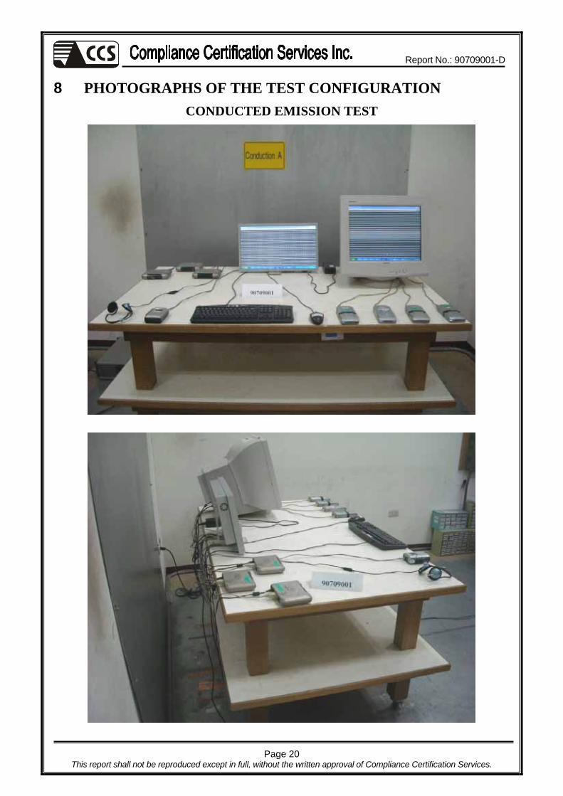
8 PHOTOGRAPHS OF THE TEST CONFIGURATION
CONDUCTED EMISSION TEST
Report No.: 90709001-D
Page 21 This report shall not be reproduced except in full, without the written approval of Compliance Certification Services.
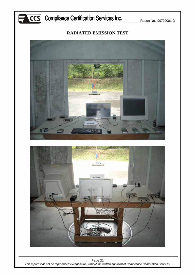
RADIATED EMISSION TEST