Embed Size (px)
Citation preview

USB
DPX
10/100Base-TX
100Base-FX
CFBRM
LACTPWR
USB10/100/10001000Base-X
LACT
PWR
100Base-X 1000Base-X USB
USBLNKLNKPWR DPX
1000Base-X 1000Base-X USB
USBLNKLNKPWR1 2
LACT FD LACT FD PWR USB
USB
DPX
10/100Base-TX
100Base-FX
CFBRM
LACTPWR
USB
10/100/10001000B
ase-X
CBFFG
LACT PWR
FBRM1xxx-1xx & BFFG1xxx-1xx Chassis & Stand-Alone Remotely Managed
Devices
Manual 33345, Revision D


Transition Networks
Table of contents
Section I: ..................................................................................................................................................................1 Product Description ................................................................................................................................................1
General description .......................................................................................................................................2 Product features .............................................................................................................................................3 Management methods...................................................................................................................................4 Hardware description....................................................................................................................................5 FBRM/BFFG13xx-1xx fiber-to-fiber gigabit models .................................................................................13 Redundant SFBRM1040-140 models ........................................................................................................15
Section II: ...............................................................................................................................................................17 Hardware Installation ...........................................................................................................................................17
Installing CFBRM/CBFFG cards into point system chassis ......................................................................18 Installing SFBRM/SBFFG standalone models ............................................................................................19 Installing fiber and copper cables ..............................................................................................................20 Connecting power (standalone models) ...................................................................................................22
Section III: ..............................................................................................................................................................24 USB Driver Installation & COM Port Setup ........................................................................................................24
Installing USB driver....................................................................................................................................25 Configuring COM port ................................................................................................................................29
Section live: ...........................................................................................................................................................32 Initial Device Setup...............................................................................................................................................32
USB CLI access ............................................................................................................................................33 Initial Device setup via USB CLI ................................................................................................................35 Initial Device setup via telnet (directly to Device) ..................................................................................38 Initial Device setup via chassis agent MMU, web-based ........................................................................41 Initial Device setup IP web-based (directly to Device) ...........................................................................44
Sections V: .............................................................................................................................................................49 Device Management.............................................................................................................................................49
SNMP IP-based management .....................................................................................................................50 Device management via chassis agent (MMU) web-based.....................................................................53 Device management via IP web-base (directly to Device) .....................................................................56
Section VI:..............................................................................................................................................................59 Software Features ..................................................................................................................................................59
Software feature descriptions .....................................................................................................................60 Software security feature descriptions .......................................................................................................69
Section VIl:.............................................................................................................................................................71 Operations .............................................................................................................................................................71
Status LEDs ...................................................................................................................................................72 OAM Device management configuration options ...................................................................................75 Firmware upgrades ......................................................................................................................................76
Continued on next page
24-Hour Technical Support: 1-800-260-1312 International: 00-1-952-941-7600 i

Transition Networks
Table of contents, continued
Section Vlll: ...........................................................................................................................................................82 Troubleshooting ....................................................................................................................................................82
Troubleshooting problem and corrective action table.............................................................................83 Section lX: ..............................................................................................................................................................88 Copper Cable & Fiber Optic Specifications .......................................................................................................88
Copper cables ..............................................................................................................................................89 Fiber optic cable and connector specifications ........................................................................................90
Section X: .............................................................................................................................................................101 Contact Us, Warranty, & Conformity Information ...........................................................................................101
Contact us...................................................................................................................................................102 Conformity declaration .............................................................................................................................103 Warranty.....................................................................................................................................................105 Compliance information ...........................................................................................................................107
Appendix A:.........................................................................................................................................................109 FBRM/BFFG Part Numbers.................................................................................................................................109
FBRM copper-to-fiber part numbers ........................................................................................................109 FBRM fiber-to-fiber part numbers ............................................................................................................112 BFFG copper-to-fiber part numbers .........................................................................................................115 BFFG fiber-to-fiber part numbers .............................................................................................................116
Appendix B: .........................................................................................................................................................120 FBRM/BFFG Technical Specification ................................................................................................................120
Specifications, notices, and warnings......................................................................................................120 Appendix C:.........................................................................................................................................................122 Device Commands & Descriptions ...................................................................................................................122 Appendix D: ........................................................................................................................................................129 IP-Based and Chassis Management Parameters ...............................................................................................129 Appendix E: .........................................................................................................................................................141 Request for Comment (RFC) Compliance .........................................................................................................141 Index.....................................................................................................................................................................143
ii

Transition Networks
Trademark, copyright information, and about this manual
Trademark All trademarks and registered trademarks are the property of their respective owners.
Copyright restrictions
© 2008 Transition Networks: All rights reserved. No part of this work may be reproduced or used in any form or by any means—graphic, electronic, or mechanical—without written permission from Transition Networks. Printed in the U.S.A.
About this manual
This manual is designed to help you find the information you need quickly. It is structured as follows: • Table of Contents (TOC) • Section TOC: Shows all the major topics in the section • Side Headings: Shows all the sub topics on each page • Index
24-Hour Technical Support: 1-800-260-1312 International: 00-1-952-941-7600 iii

Transition Networks
Caution and warnings
Definitions Cautions indicate that there is the possibility of poor equipment performance or
damage to the equipment. The symbol below identifies cautions Warnings indicate that there is the possibility of injury to person.
Cautions and Warnings appear here and may appear throughout this manual where appropriate. Failure to read and understand the information identified by the symbol could result in poor equipment performance, damage to the equipment, or injury to persons.
Cautions
When handling chassis Devices observe electrostatic discharge precautions. This requires proper grounding; i.e., wear a wrist strap.
Copper based media ports, e.g., Twisted Pair (TP) Ethernet, USB, RS232, RS422, RS485, DS1, DS3, Video Coax, etc., are intended to be connected to intra-building (inside plant) link segments that are not subject to lightening transients or power faults.
Copper based media ports, e.g., Twisted Pair (TP) Ethernet, USB, RS232, RS422, RS485, DS1, DS3, Video Coax, etc., are NOT to be connected to inter-building (outside plant) link segments that are subject to lightening.
DO NOT install the Devices in areas where strong electromagnetic fields (EMF) exist. Failure to observe this caution could result in poor Device performance.
Warnings
Use of controls, adjustments or the performance of procedures other than those specified herein may result in hazardous radiation exposure.
Visible and invisible laser radiation when open. DO NOT stare into the beam or view the beam directly with optical instruments. Failure to observe this warning could result in an eye injury or blindness.
iv

Transition Networks
Section I:
Product Description
In this section These are the topics:
Topic See Page General description 2 Product features 3 Management methods 4 Hardware description 5 FBRM/BFFG13xx-1xx fiber-to-fiber gigabit models 13 Redundant SFBRM1040-140 models 15
24-Hour Technical Support: 1-800-260-1312 International: 00-1-952-941-7600 1

Section I: FBRM/BFFG Product Description Transition Networks
General description
Design and configuration
The FBRM and BFFG Devices are designed as standalone models, and also as slide-in Devices for the Point System chassis. These Devices can be managed through SNMP via the Focal Point software (free), Web-based management, Local SNMP, and USB interfaces. The CFBRM and CBFFG (chassis Devices), and SFBRM and SBFFG (standalone Devices) are designed to manage Devices remotely through the copper and fiber ports. The FBRM or BFFG Devices installed on a network should be configured one as the local peer and the other as a remote peer for management. Remote management is accomplished using OAM (Operation Administration and Maintenance) per the IEEE 802.3ah, 2004 standard. Standalone Devices can also be managed via IP (Web-based) or Telnet.
What is OAM? These Devices implement the IEEE 802.3ah standard or (OAM) in the Ethernet first
mile. OAM is a group of network management functions that provide network fault indications, performance information, data, and diagnosis. These Devices implement remote management via OAM as per the IEEE 802.3ah standard.
In-band management
These Devices implement complete Real-Time Multi-Threaded Operating System (RTOS) with a TCP/IP stack for in-band management.
USB interface The USB (Universal Serial Bus) type “B” serial port is used mainly to configure
Device-basic setup before installation and operation on a network.
Point System mgmt interface
Implements the current Point System management I2C interface. This allows managing the Device via SNMP, using the existing Point System method.
2

Transition Networks Section I: FBRM/BFFG Product Description
Product features
Supported features
The following is a list of the major FBRM and BFFG Device supported features: • Remote Management via OAM (IEEE 802.3ah) and IP-based management • AutoCross • Transparent Link pass-through with automatic link restoration • Far end fault detection on fiber ports • OAM IEEE 802.3ah • Auto-Negotiation (enable/disable) • Force 10 Mbs or 100 Mbs speed (non-gigabit models only) • Force half or full duplex • Pause capability • Automatic firmware upgrade via OAM • Forwards all IEEE multicast frames including STP/LACP/LAMP • Enable/disable USB port access • Enable/disable SNMP queries • Enable/disable system-level IP management or on a per port basis • IEEE 802.1q VLAN (virtual local area network) • Management VLAN for all management frames • IEEE 802.1x port-based network access control • Radius authentication for management • Remote and local firmware upgrades via TFTP (Trivial File Transfer Protocol) or
Xmodem
24-Hour Technical Support: 1-800-260-1312 International: 00-1-952-941-7600 3

Section I: FBRM/BFFG Product Description Transition Networks
Management methods
Management The FBRM and BFFG Devices support the following management methods:
• USB CLI (Command Line Interface) • Telnet • MMU (Management Module Unit) chassis web-based • IP-based (web-based directly to the Device)
USB USB management requires a direct connection to the Device via a computer. This
method is used to set up initially or to troubleshoot Devices in the field.
Telnet Telnet management requires that the Device be connected to a network. Then from
the CPU command line type Telnet and the Device IP address as shown as follows: Telnet nnn.nnn.nnn.nnn (represents Device IP address).
MMU The MMU (Management Module Unit) is the heart of the Point System chassis’
management capability. It has the ability to monitor and manage all its installed Devices. The MMU communicates through the CLI presented at the serial port, or through SNMP, Telnet CLI, and Web interface available via the Ethernet port.
IP-based (web-based)
The switch provides complete management through IP via an SNMP interface, web-browser, or Telnet. The Device provides an embedded web server for web-based management. It also offers advanced management features and enables Device management from anywhere on the network through a standard browser, such as Microsoft Internet Explorer or Netscape.
4

Transition Networks Section I: FBRM/BFFG Product Description
Hardware description
Front panel CFBRM
The front panel of the CFBRM10xx-1xx Devices has the following ports and LEDs:
Ports Front Panel LEDs • Power (one) One RJ-45 auto-sensing of 10Base or 10/100Base-TX UTP connections
• RJ-45 port (two)
One 100Base-FX/LX/BX fiber either SC or ST connectors • LACT (one) • DPX (one)
One USB • USB (one)
Figure 1: Chassis CFBRM10xx-1xx Device Front Panel
Note: The LEDs and ports are the same on the SFBRM10xx-1xx standalone models.
Continued on next page
24-Hour Technical Support: 1-800-260-1312 International: 00-1-952-941-7600 5

Section I: FBRM/BFFG Product Description Transition Networks
Hardware description, continued
Front panel CFBRM
The front panel of the CFBRM 1040-140 Devices has the following ports and LEDs:
Ports Front Panel LEDs • Power (one) 100Base-FX SFP port • Link/Active 10/100 Base-T copper port • Speed
• Duplex (one) One USB • USB (one)
Figure 2: CFBRM1040-100 Front Panel
Note: The LEDs and ports are the same on the SFBRM1040-140 standalone
models.
Continued on next page
6

Transition Networks Section I: FBRM/BFFG Product Description
Hardware description, continued
Front panel CFBRM Gbit
The front panel of the CFBRM13xx-1xx Devices has the following ports and LEDs:
Ports Front Panel LEDs • Power (one) One 100 Base-T • Fiber-Port Link (one)One 1000Base-FX/LX/BX fiber either SC or ST connectors • Fiber-Port Link (one)One USB • USB (one)
Fiber LinkLED
Fiber LinkLED
PowerLED USB LED
SC ConnectorFiber
SC ConnectorFiber USB Port
USBLNKPWR LNK
100Base-T 1000Base-X
Figure 3: Chassis CFBRM13xx-1xx Device Front Panel
Note: The LEDs and ports are the same on the SFBRM13xx-1xx standalone models.
Continued on next page
24-Hour Technical Support: 1-800-260-1312 International: 00-1-952-941-7600 7

Section I: FBRM/BFFG Product Description Transition Networks
Hardware description, continued
Front panel CBFFG Gbit
The front panel of the CBFFG10xx-1xx Devices has the following ports and LEDs:
Ports Front Panel LEDs • Power (one) 1000Base-SX/LX/BX fiber SC port • Link/Active 10/100/1000Base-T copper port • Speed
• Duplex (one) One USB • USB (one)
Figure 4: CBFFG10xx-1xx Device Front Panel
Note: The LEDs and ports are the same on the SBFFG10xx-1xx standalone
models.
Continued on next page
8

Transition Networks Section I: FBRM/BFFG Product Description
Hardware description, continued
Front panel CBFFG Gbit
The front panel of the CBFFG1040-1xx Devices has the following ports and LEDs:
Ports Front Panel LEDs • Power (one) 1000Base SFP port • Link/Active 10/100/1000Base-T copper port • Speed
• Duplex (one) One USB • USB (one)
USB10/100/10001000Base-X
SpeedDuplex/Link
USB LED
Power
Link Active
SFP PortUSB Port
RJ45 Port Figure 5: CBFFG1040-1xx Device Front Panel
Note: The LEDs and ports are the same on the SBFFG1040-1xx standalone
models.
Continued on next page
24-Hour Technical Support: 1-800-260-1312 International: 00-1-952-941-7600 9

Section I: FBRM/BFFG Product Description Transition Networks
Hardware description, continued
Front panel CBFFG Gbit
The front panel of the CBFFG13xx-1xx Devices has the following ports and LEDs:
Ports Front Panel LEDs • Power (one) Two 1000Base-FX/LX/BX fiber either SC or ST connectors • Fiber-Port Link (two)
• Duplex (one) One USB • USB (one)
Figure 6: Chassis CBFFG13xx-1xx Device Front Panel
Note: The LEDs and ports are the same on the SBFFG13xx-1xx standalone models.
Continued on next page
10

Transition Networks Section I: FBRM/BFFG Product Description
Hardware description, continued
Front panel SFBRM
The front panel of the SFBRM1040-140 redundant Devices has the following ports and LEDs:
Ports Front Panel LEDs • Power (one) 1000Base SX/LX SFP ports (2 and 3) • Link/Active
• Duplex 10/100/1000Base-T copper port (1) • Speed
• Duplex (one) One USB • USB (one)
Figure 7: CBFFG1040-140 Device Front Panel
Continued on next page
24-Hour Technical Support: 1-800-260-1312 International: 00-1-952-941-7600 11

Section I: FBRM/BFFG Product Description Transition Networks
Hardware description, continued
Rear panel (standalone)
On the standalone SFBRM and SBFFG Devices only, the rear panel consists of a power-barrel connector for connecting power via a power adaptor. See Figure 8.
Figure 8: SFBRM/SBFFG 1xxx-1xx Device Real Panel (Standalone Only)
Note: The Point System chassis powers the CFBRM and CBFFG chassis Devices.
12

Transition Networks Section I: FBRM/BFFG Product Description
FBRM/BFFG13xx-1xx fiber-to-fiber gigabit models
Gigabit (Gbit) models
The FBRM100Base-FX-to-1000Base-X and the BFFG 1000Base-X-to-1000Base-X are the Gbit versions of the IEEE 802.3ah managed Devices. The BFFG models link Gbit fiber connections; the FBRM models convert 100Base-Fx 100 Mbit/s to Gbit. These Devices function generally in the same manner as copper-to-fiber FBRMs, the difference is the way the ports are configured. See Tables 1 and 2.
Table 1: FBRM13xx-1xx 100Base-FX-to-1000Base-X Device Port Configuration Port 1: 100Base-FX • Default setting: 100Mbs and full duplex.
• FEFI (Far-end fault indication) is configurable. Port 2: 1000Base-X Default:
• Auto-Negotiation enabled. • OAM enabled and in Active Mode if chassis Device
(passive if standalone).
Table 2: BFFG13xx-1xx 1000Base-X-to-1000Base-X Device Port Configuration Port 1: 1000Base-X Default: Auto-Negotiation enabled. Port 2: 1000Base-X Default:
• Auto-Negotiation enabled. • OAM is enabled and in Active Mode if chassis Device
(passive if standalone).
Continued on next page
24-Hour Technical Support: 1-800-260-1312 International: 00-1-952-941-7600 13

Section I: FBRM/BFFG Product Description Transition Networks
FBRM/BFFG13xx-1xx fiber-to-fiber gigabit models, continued
Connectivity The different versions of the FBRM and BFFG can be connected and set up to
manage a remote peer completely. In a mixed setup with other FBRM or BFFG Devices, consider the connectivity scenarios in Figure 9, and the explanation that follows:
Figure 9: Connectivity Scenarios
Connection scenario explanation
In Figure 9, P2 of the active local peer in both scenarios is “OAM enabled” and “Active” by default. To manage the remote passive peer via OAM, configure P1 of the active local peer as follows: • Enable OAM • Select Active mode If the connection to the passive remote peer is made thru P2 of the active local peer, OAM occurs without human intervention.
Note: Automatic firmware upgrades will not occur with different types of FBRM
or BFFG Device configurations.
14

Transition Networks Section I: FBRM/BFFG Product Description
Redundant SFBRM1040-140 models
Redundant models
These SFBRM SFP Devices support fiber redundancy. They have two (2) fiber SFP ports and one (1) copper port. When you tag the fiber ports as primary and secondary with redundancy enabled, any fault on the primary port results in the secondary port becoming operational. There is an option for reverting back to the primary once it has been restored, or you can continue using the secondary port—these are user selectable features. See Figure 10.
Figure 10: SFBRMs in Redundant Mode
Explanation With Port 3 as the secondary port in Redundancy Mode and Port 2, the primary goes
down, the following will happen:
Stage Description A. All Physical layer and OAM configurations of Port 2 will be applied to
Port 3. B. Port 2 is disabled, and Port 3 initialized to take over. C. An SNMP trap is sent indicating that the ports have switched. D. OAM reinitializes (resets all OAM counters and event logs). E. All the dynamic MAC entries in the ATU are flushed and the active port
has to relearn the entries.
Note: If the configuration option “revert” is set, when the primary port link is restored the session will revert back to the primary port. If the “revert’ option is NOT SET and the primary link is restored, the secondary port remains in operation until the user intervenes.
Continued on next page
24-Hour Technical Support: 1-800-260-1312 International: 00-1-952-941-7600 15

Section I: FBRM/BFFG Product Description Transition Networks
Redundant SFBRM1040-140 models, continued
3-port switch mode
In this mode, the Device acts as a 3-port switch with the fiber port connected to 2 remote Devices. See Figure 11.
Figure 11: 3-Port Switch Mode
Note: In 3-port switch mode:
• Only one OAM session can be active at anytime. • Transparent Link pass through is not applicable in this scenario. The port
link status from the Devices is received only as SNMP traps.
16

Transition Networks
Section II:
Hardware Installation
Introduction This section describes how to install the CFBRM and CBFFG Devices into a Point
System chassis with a remotely managed SFBRM or CFBRM standalone Device. Also, shows how to install two SFBRM Devices or two SBFFG standalone Devices on a network, one as a local Device and the other as a remotely managed Device.
Caution When handling chassis Devices observe electrostatic discharge precautions.
This requires proper grounding; i.e., wear a wrist strap. Failure to observe this caution could result in damage to the chassis Device.
In this section These are the topics:
Topic See Page Installing CFBRM/CBFFG Devices into a point system chassis 18 Installing SFBRM/SBFFG standalone models 19 Installing copper and fiber cables 20 Connecting power (standalone models) 22
24-Hour Technical Support: 1-800-260-1312 International: 00-1-952-941-7600 17

Section ll: FBRM/BFFG Hardware Installation Transition Networks
Installing CFBRM/CBFFG Devices into point system chassis
IMPORTANT The CFBRM/CBFFG Device product family IS NOT compatible with the CPSMM-
200 and CPSMM-210 MGMT modules when used in a cascaded application. The CFBRM/CBFFG can be installed in the “master” chassis with the CPSMM-200 MGMT module, but they can not be installed in a cascaded chassis using the CPSMM-210 MGMT module. Alternatively, the CFBRM/CBFFG can be used with the CPSMM120 MGMT module, which does not support chassis cascading.
Caution Wear a grounding strap and observe electrostatic discharge precautions when
installing the CFBRM/CBFFG Device into the Point System chassis. Failure to observe this caution could result in damage to the Device.
Chassis Device installation
To install the chassis Device into the Point System chassis, do the following:
Step Action 1. Locate an empty slot in the Point System chassis. 2. Grasp the edges of the Device by its front panel. 3. Align the Device with the slot guides and carefully insert the Device into
the installation slot. 4. Firmly seat the Device against the chassis back panel. 5. Push IN and ROTATE clockwise the panel-fastener screw to secure the
Device to the chassis. See Figure 12.
Figure 12: CFBRM/CBFFG Device Chassis Installation
18

Transition Networks Section ll: FBRM/BFFG Hardware Installation
Installing SFBRM/SBFFG standalone models
Standalone installation
Figure 13 shows a typical installation involving two (2) SFBRM/SBFFG standalone Devices on a network.
Figure 13: Installation with Two SFBRM/SBFFG Standalone Devices
Note: With the local active standalone Device connected to a remote standalone
passive Device and with “Mode Control” set to “Auto,” the local (active) Device will manage the remote (passive) Device. This relationship is established automatically.
24-Hour Technical Support: 1-800-260-1312 International: 00-1-952-941-7600 19

Section ll: FBRM/BFFG Hardware Installation Transition Networks
Installing fiber and copper cables
Warning
Use of controls, any adjustments, or the performance of procedures other than those specified herein may result in hazardous radiation exposure.
Visible and invisible laser radiation when open: DO NOT stare into the laser-light beam or view the beam directly with optical instruments. Failure to observe this warning could result in an eye injury or blindness.
Fiber cable To install the fiber cable, do the following:
Step Action 1. Locate a 100/1000Base-FX/SX/LX compliant fiber cable with male,
two-stranded connectors installed at both ends. See Figure 14. 2. Connect the fiber cables to the FBRM or BFFG Devices as shown in
Figure 14.
Figure 14: Fiber Cable Installation
Continued on next page
20
Transition Networks Section ll: FBRM/BFFG Hardware Installation
Installing fiber and copper cables, continued
Caution
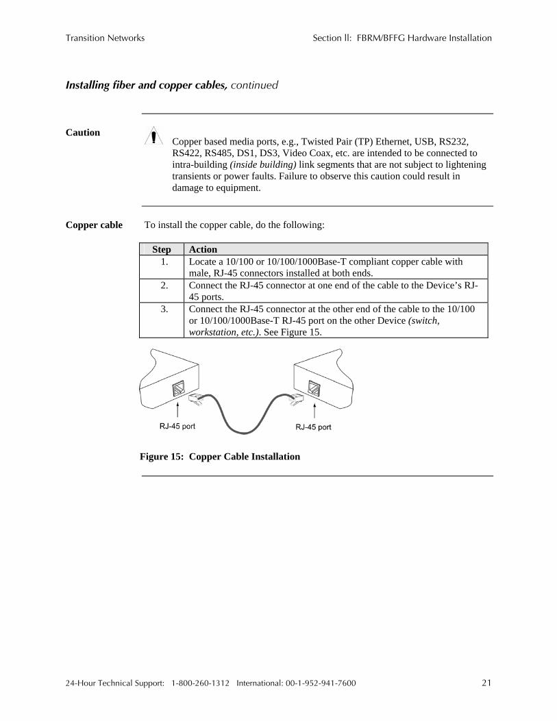
Copper based media ports, e.g., Twisted Pair (TP) Ethernet, USB, RS232, RS422, RS485, DS1, DS3, Video Coax, etc. are intended to be connected to intra-building (inside building) link segments that are not subject to lightening transients or power faults. Failure to observe this caution could result in damage to equipment.
Copper cable To install the copper cable, do the following:
Step Action 1. Locate a 10/100 or 10/100/1000Base-T compliant copper cable with
male, RJ-45 connectors installed at both ends. 2. Connect the RJ-45 connector at one end of the cable to the Device’s RJ-
45 ports. 3. Connect the RJ-45 connector at the other end of the cable to the 10/100
or 10/100/1000Base-T RJ-45 port on the other Device (switch, workstation, etc.). See Figure 15.
Figure 15: Copper Cable Installation
24-Hour Technical Support: 1-800-260-1312 International: 00-1-952-941-7600 21

Section ll: FBRM/BFFG Hardware Installation Transition Networks
Connecting power (standalone models)
Chassis powers slide-in Device
Transition Networks’ Point System chassis powers the CFBRM/CBFFG chassis Devices.
Adapter powers standalone
Use an AC power adaptor to power the SFBRM/SBFFG standalone Device. To connect power to the Device, do the following:
Step Action
1. Connect the barrel connector on the power adapter cord to the power connector on the Device (located on the rear of the Device). See Figure 16.
Figure 16: Standalone Device Power Connector
2. Connect the power adapter plug into AC power. 3. Verify that the Device has powered UP—the power indicator LED will be
lit.
22

Transition Networks Section ll: FBRM/BFFG Hardware Installation
Intentionally Blank
24-Hour Technical Support: 1-800-260-1312 International: 00-1-952-941-7600 23

Transition Networks
Section III:
USB Driver Installation & COM Port Setup Introduction This section shows how to install the USB driver and configure COM ports.
In this section These are the topics:
Topic See Page Installing USB driver 25 Configuring COM ports 29
24-Hour Technical Support: 1-800-260-1312 International: 00-1-952-941-7600 24

Transition Networks Section lll: FBRM/BFFG1 Driver Installation & COM Port Setup
Installing USB driver
USB driver The driver installation instructions are for Windows XP only. Installing the USB
driver using Windows 2000 is similar, but not necessarily identical to the following Windows XP driver-installation procedure.
Note: The following USB drivers are provided with the product on a CD, also
available at www.ftdichip.com (click on drivers): WinXP64, Win Server 2003, Win 2002, Win ME/98, Mac OS X, 9, 8, and Linux.
Installing USB driver
To install the USB driver on a computer with a Windows XP OS, do the following:
Step Action 1. Extract the driver (provided CD or from website) and place it in an
accessible folder on the local drive. 2. Plug the Device into the USB port on the PC to bring up the “found new
hardware” wizard dialog box, shown in Figure 17. 3. Select RADIO button, “No, not this time” as shown in Figure 17.
Figure 17: Found New Hardware Wizard Dialog Box
Continued on next page
24-Hour Technical Support: 1-800-260-1312 International: 00-1-952-941-7600 25

Section lll: FBRM/BFFG USB Driver Installation & COM Port Setup Transition Networks
Installing USB driver, continued
Installing USB driver (continued)
Step Action 4. Click the NEXT button to launch the “installation options” dialog box. 5. Select RADIO button “Install from a list or specific location
(Advanced)” as shown in Figure 18.
Figure 18: Installation Options Dialog Box
6. Click the NEXT button to bring up the “driver search installation
options” dialog boxes shown in Figure 19.
Figure 19: Driver Search Installation Options Dialog Box
Continued on next page
26

Transition Networks Section lll: FBRM/BFFG1 Driver Installation & COM Port Setup
Installing USB driver, continued
Step Action 7. Use the BROWSE button to locate the USB driver, as shown in
Figure 20.
Figure 20: Driver Location
8. Click the NEXT button to start installing the driver and the driver-install
screen will appear as XP copies the Device driver. See Figure 21.
Figure 21: Windows XP Installing Driver Box
Continued on next page
C:\FBRM/BFFG1xx
FBRM/BFFG1xx Driver
24-Hour Technical Support: 1-800-260-1312 International: 00-1-952-941-7600 27

Section lll: FBRM/BFFG USB Driver Installation & COM Port Setup Transition Networks
Installing USB driver, continued
Step Action 9. After the driver installation is successful, the “finished installing” dialog
box will appear, as shown in Figure 22.
Figure 22: Finish Installing Driver Dialog Box
10. Click the FINISH button and a “found new hardware” message will
appear on the lower right side of the screen, as shown in Figure 23.
Figure 23: New Hardware Installed and Ready to Use
28

Transition Networks Section lll: FBRM/BFFG1 Driver Installation & COM Port Setup
Configuring COM port
Getting COM port number
You need the COM port number to configure the terminal emulator. To get the COM port number, do the following:
Step Action 1. On the desktop, right click on the “my computer” icon and select
“Device manager” to open the “computer management” window. 2. Click on “Device manager” to open the Device manager’s panel (screen
right panel) shown in Figure 24.
Figure 24: Computer Management Window
3. Expand the Ports (COM & LPT) in the right column and write down the USB COM port number for configuring the terminal emulator software used for the USB Device.
Continued on next page
24-Hour Technical Support: 1-800-260-1312 International: 00-1-952-941-7600 29

Section lll: FBRM/BFFG USB Driver Installation & COM Port Setup Transition Networks
Configuring COM port, continued
Terminal emulator setup
To set up the terminal emulator software, e.g., HyperTerminal to use the USB COM port, do the following:
Step Action 1. Activate the “HyperTerminal” software to bring up the “connection
description” dialog box, shown in Figure 25.
Figure 25: Connexion Description Diallo Box
2. Type in a name and select an icon. 3. Click the OK button to launch the “connect to” dialog box, shown in
Figure 26.
Figure 26: Connect To Dialog Box
Continued on next page
30

Transition Networks Section lll: FBRM/BFFG1 Driver Installation & COM Port Setup
Configuring COM port, continued
Terminal emulator setup (continued)
Step Action 4. Select the COM port identified for the USB Device shown in the Device
manager. 5. Click the OK button to bring up the “port settings” dialog box, shown in
Figure 27.
Figure 27: COM Port Settings Dialog Box
6. Set the COM port properties as follows:
• Baud: 57600 • Data length: 8 • Parity: None • Stop bit: 1 • Flow Control: None
7. Click the OK button and the Device login prompt will appear.
24-Hour Technical Support: 1-800-260-1312 International: 00-1-952-941-7600 31

Transition Networks
Section live:
Initial Device Setup
Introduction There are four ways to set up the FBRM/BFFG 1xxx-1xx Devices before the Device
can be operated and managed: • USB CLI • Telnet • Chassis MMU (chassis model) • IP-based (directly to FBRM/BFFG)
The factory default IP configuration is the following: • IP address: 192.168.1.1 • Subnet Mask: 255.255.255.0 • Gateway: 192.168.1.2
In this section These are the topics:
Topic See Page USB CLI access 33 Initial Device setup via USB CLI 35 Initial Device setup via Telnet (directly to Device) 38 Initial Device setup via chassis agent (MMU) web-based 41 Initial Device setup via IP web-based (directly to Device) 44
24-Hour Technical Support: 1-800-260-1312 International: 00-1-952-941-7600 32

Transition Networks Section lV: FBRM/BFFG Initial Device Setup
USB CLI access
Accessing the USB CLI
To access the USB CLI, do the following:
Step Action 1. Connect the Device to a computer via the USB port. 2. Activate the terminal emulator software to launch the emulator screen. 3. Press the ENTER key to bring up the “password” prompt. 4. Enter the password and then the login (default is “root” in both cases) to
bring up the Device console> prompt, shown in Figure 28.
Figure 28: Device Console Prompt
5. To access the commands list, at the console> prompt type help or “?” 6. Press the ENTER key to launch the “commands” screen, shown in
Figure 29.
Figure 29: Commands for FBRM/BFFGs Models
Note: See Appendix C for a complete list of the configuration commands and definitions. All CLI commands are case sensitive.
Continued on next page
Password : Login : root Password : Console:/>_
24-Hour Technical Support: 1-800-260-1312 International: 00-1-952-941-7600 33

Section IV: FBRM/BFFG Initial Device Setup Transition Networks
USB CLI access, continued
Redundant The following is the screen of commands for the redundant SFP Devices.
Figure 30: Commands for Redundant SFP Models
34

Transition Networks Section lV: FBRM/BFFG Initial Device Setup
Initial Device setup via USB CLI
IP configuration
Use the ‘set’ commands to set the IP configuration through the USB port. Configure the Device with a network IP address, subnet mask, and default gateway. Set the IP address via USB CLI (Command Line Interface), or via DHCP (Dynamic Host Configuration Protocol), which is disabled by default.
Factory default IP config
The factory default IP configuration shipped with the Device is as follows: • IP address: 192.168.1.1 • Subnet Mask: 255.255.255.0 • Gateway: 192.168.1.2
Note: Type “help set <command>” to display the format used to set the commands.
Set IP config via USB CLI
To set the IP via the USB CLI, do the following:
Step Action 1. At the console> prompt type set ip=nnn.nnn.nnn.nnn 2. Press the ENTER key to set the IP address. 3. At the console> prompt type set netmask=nnn.nnn.nnn.nnn 4. Press the ENTER key to set the netmask. 5. At the console> prompt type set gateway=nnn.nnn.nnn.nnn 6. At the console> prompt type save 7. Press the ENTER key to save the new IP configuration.
Continued on next page
24-Hour Technical Support: 1-800-260-1312 International: 00-1-952-941-7600 35

Section IV: FBRM/BFFG Initial Device Setup Transition Networks
Initial Device setup via USB CLI, continued
DHCP method To set the IP configuration via the DHCP in console mode, do the following:
Note: A DHCP server must be on the network and accessible before using this method.
Step Action
1. At the console> prompt type set dhcp=enable 2. Press the ENTER key and the screen will appear as shown in Figure 31.
Figure 31: Enable DHCP
3. Type reboot 4. Press the ENTER key to reboot the Device and start the DHCP process.
Note: DHCP “successful” will appear on the screen when completed, or “failed” if
not successful.
Continued on next page
36

Transition Networks Section lV: FBRM/BFFG Initial Device Setup
Initial Device setup via USB CLI, continued
Show system configuration
To show the Device system configuration, do the following:
Step Action 1. At the console> prompt type show 2. Press the ENTER key to bring up the Device system configuration screen,
shown in Figure 32.
Figure 32: Example System Configuration Screen
24-Hour Technical Support: 1-800-260-1312 International: 00-1-952-941-7600 37

Section IV: FBRM/BFFG Initial Device Setup Transition Networks
Initial Device setup via telnet (directly to Device)
To set up the Device initially via telnet directly to the Device, do the following:
Initial setup via Telnet to Device
Step Action 1. At the command line type: Telnet nnn.nnn.nnn.nnn (IP address of the Device) to
bring up the password prompt, shown in Figure 33.
Figure 33: Password Prompt
Type the case-sensitive username and password (default is ‘root’ for both).
2.
3. Press the ENTER key to launch the console prompt, shown in Figure 34.
Figure 34: Console Prompt
Continued on next page
38

Transition Networks Section lV: FBRM/BFFG Initial Device Setup
Initial Device setup via telnet (directly to Device), continued
Step Action
At the console:/> prompt type show 4. 5. Press the ENTER key to display the system configuration, as shown in
Figure 35.
Figure 35: System Configuration Screen
Continued on next page
24-Hour Technical Support: 1-800-260-1312 International: 00-1-952-941-7600 39

Section IV: FBRM/BFFG Initial Device Setup Transition Networks
Initial Device setup via telnet (directly to Device), continued
Step Action
6. At the console prompt type: help 7. Press the ENTER key to show the commands, shown in Figure 36.
Figure 36: Device Command Screen
Note: The CLI and Telnet interface commands are structured in the same manner.
Terminating telnet
To disconnect the Telnet client from the management module server, press the CTRL-D keys, or at the console prompt type: exit or logoff
40

Transition Networks Section lV: FBRM/BFFG Initial Device Setup
Initial Device setup via chassis agent MMU, web-based
Setup via Web to MMU
To set up the Device initially via the MMU web-based, do the following:
Step Action 1. Open a web browser. 2. At the URL type the IP address of the chassis (MMU). 3. Click the GO button to bring up the password screen, shown in Figure 37.
Figure 37: Chassis Agent (MMU) Log In Screen
Type the password (default is private). 4.
5. Press the ENTER key to launch the chassis agent’s main menu, shown in Figure 38.
Figure 38: Chassis Agent (MMU) Main Menu
6. Click the VIEW button to show the Devices in the chassis and the screen
will appear, as shown in Figure 39.
Figure 39: Point System Chassis Main Menu
Continued on next page
24-Hour Technical Support: 1-800-260-1312 International: 00-1-952-941-7600 41

Section IV: FBRM/BFFG Initial Device Setup Transition Networks
Initial Device setup via chassis agent MMU, web-based, continued
Step Action
7. Click the VIEW button of the CFBRM/CBFFG Device in slot 9 to show the local configuration screen for the Device. See Figure 40.
Note: You can configure the IP along with other Device parameters on this screen.
Figure 40: Local Switch FBRM/BFFG Configuration Screen
Note: DO NOT use the browser BACK button to navigate the screens. This will
cause the connection to drop.
Continued on next page
42

Transition Networks Section lV: FBRM/BFFG Initial Device Setup
Initial Device setup via chassis agent MMU, web-based, continued
IP config via DHCP
To configure the IP via DHCP, do the following:
Step Action 1. A DHCP server must be on the network and accessible. 2. On the local switch configuration screen, enable DHCP. 3. On the local switch configuration screen set item Reset Switch to “Yes.” 4. Click the SAVE/EXECUTE button to start the DHCP process.
Note: To verify that the DHCP IP configuration was successful, check the IP
configuration for the Device on the local switch screen and note the changes to the IP configuration.
24-Hour Technical Support: 1-800-260-1312 International: 00-1-952-941-7600 43

Section IV: FBRM/BFFG Initial Device Setup Transition Networks
Initial Device setup IP web-based (directly to Device)
Initial setup via IP to Device
To set up the Device initially via a IP web-based, do the following:
Step Action 1. Open a web browser. 2. At the URL type in the FBRM/BFFG default IP address. 3. Click the GO button to launch the password screen shown in Figure 41.
Figure 41: Login Screen
Type the password (default is private). 4.
5. Press the ENTER key to launch the FBRM/BFFG main menu, as shown in Figure 42.
Figure 42: FBRM/BFFG Main Menu
Continued on next page
44

Transition Networks Section lV: FBRM/BFFG Initial Device Setup
Initial Device setup IP web-based (directly to Device), continued
Step Action
6. Click the local system configuration VIEW button to show the local system configuration menu, shown in Figure 43.
Note: You can configure the IP along with other Device parameters on this screen.
Figure 43: FBRM/BFFG Local System Configuration Screen
Note: DO NOT use the browser BACK button to navigate the screens. This will cause the connection to drop.
Continued on next page
24-Hour Technical Support: 1-800-260-1312 International: 00-1-952-941-7600 45

Section IV: FBRM/BFFG Initial Device Setup Transition Networks
Initial Device setup IP web-based (directly to Device), continued
IP config via DHCP
To set up the IP configuration via DHCP, do the following:
Step Action 1. A DHCP server must be on the network and accessible. 2. On the local switch configuration screen, enable DHCP as shown in Figure
44.
Figure 44: IP-based Local System Configuration Screen
3. Click the Local REBOOT button at the top of the screen to start the DHCP
process.
Note: To verify that the DHCP IP configuration was successful, check the IP configuration for the Device on the local system configuration screen and note the changes to the IP configuration.
Continued on next page
46

Transition Networks Section lV: FBRM/BFFG Initial Device Setup
Initial Device setup IP web-based (directly to Device), continued
Redundant Devices
To set up the redundant feature for the stand-alone 3-port FBRM SFP Device via IP web-based, do the following:
Step Action
1. Open a web browser. 2. At the URL type in the SFBRM default IP address. 3. Click the GO button to launch the password screen shown in Figure 45.
Figure 45: Login Screen
Type the password (default is private). 4. 5. Press the ENTER key to launch the SFBRM main menu, as shown in
Figure 46.
Figure 46: Redundant Device Main Menu
Continued on next page
24-Hour Technical Support: 1-800-260-1312 International: 00-1-952-941-7600 47

Section IV: FBRM/BFFG Initial Device Setup Transition Networks
Initial Device setup IP web-based (directly to Device), continued
Step Action
6. Click the advance system configuration VIEW button to show the redundancy configuration parameters, shown in Figure 47.
Figure 47: Redundancy Configuration Screen
Note: The redundancy features are specific to the 3-port SFBRM SFP Device only.
48

Transition Networks
Sections V:
Device Management
In this section These are the topics:
Topic See Page SNMP IP-based management 50 Device management via chassis MMU web-based 53 Device management via IP (directly to Device) 56
24-Hour Technical Support: 1-800-260-1312 International: 00-1-952-941-7600 49

Section V: FBRM/BFFG Device Management Transition Networks
SNMP IP-based management
SNMP The FBRM/BFFG Device provides complete management through the SNMP
interface. It supports the following standard MIBs for management, using SNMPv1: • RFC 1213 (MIB- II) • RFC 2819 (RMON – statistics group) • RFC 2863 (IF MIB counters) • RFC 3635 (Ether-like MIB counters) • RFC 1493 (Bridge MIB objects counters) • RFC 2674 (Bridge extension counters) I-D: draft-ietf-hubmib-efm-mib (EFM OAM mib – the EFM hub mib is added to the TN private tree since it has not been added to the ISO tree.) Use the provide version shipped on the CD with your Device. See Figure 48.
EFM-Hub MIBs
Figure 48: EFM Hub MIBs Added to Private Tree
Continued on next page
50 24-Hour Technical Support: 1-800-260-1312 International: 00-1-952-941-7600

Transition Networks Section V: FBRM/BFFG Device Management
SNMP IP-based management, continued
The TN private MIBs for SNMP IP-based management feature extensive management options. Some of the features are the following:
TN private MIBs
• Copper and fiber link status • Copper and fiber port duplex • Administratively enable/disable port • Copper port speed • Enable/disable Auto-Negotiation (copper) • Enable/disable Pause • Enable/disable capability advertisement for speed and duplex • RMON statistics • AutoCross on copper port • Remote fault detect • Enable/disable far-end fault on fiber • Transparent link-pass through • 802.3ah OAM enable/disable on all ports • OAM channel statistics • OAM remote loopback • Rate limiting/band width allocation using fixed rate sets • IP traffic class priority • 802.1q VLAN support • Virtual cable test The remote Device can be managed completely through OAM. Figure 49 shows an example of a private MIB objects tree.
Continued on next page
24-Hour Technical Support: 1-800-260-1312 International: 00-1-952-941-7600 51

Section V: FBRM/BFFG Device Management Transition Networks
SNMP IP-based management, continued
MIB objects Figure 49 shows the placement of the MIB objects on the private tree.
Private MIB Objects
Figure 49: Private MIB Objects
52 24-Hour Technical Support: 1-800-260-1312 International: 00-1-952-941-7600

Transition Networks Section V: FBRM/BFFG Device Management
Device management via chassis agent (MMU) web-based
Management via MMU
To set up the FBRM/BFFG initially via the MMU, do the following:
Step Action 1. Open a web browser. 2. At the URL type the IP address of the chassis (MMU). 3. Click the GO button to launch the password screen. See Figure 50.
Figure 50: Chassis Agent (MMU) Login Screen
Type the password (default is private). 4. 5. Press the ENTER key to launch the chassis agent’s main menu, as shown
in Figure 51.
Figure 51: Chassis Agent (MMU) Main Menu
6. Click the VIEW button to show the Devices in the cabinet slots, as shown
in Figure 52.
Figure 52: Devices in Chassis Slots
Continued on next page
24-Hour Technical Support: 1-800-260-1312 International: 00-1-952-941-7600 53

Section V: FBRM/BFFG Device Management Transition Networks
Device management via chassis agent (MMU) web-based, continued
Step Action
7. Click the VIEW button of the CFBRM/CBFFG Device to bring up the local switch management screen. See Figure 53.
Figure 53: Local Switch Configuration Screen
8. Scroll down to the LOCAL PORT buttons, shown in Figure 54.
Figure 54: Local System Configuration Local Port Buttons
Note: DO NOT use the browser BACK button to navigate the screens. This will
cause the connection to drop.
Continued on next page
54 24-Hour Technical Support: 1-800-260-1312 International: 00-1-952-941-7600

Transition Networks Section V: FBRM/BFFG Device Management
Device management via chassis agent (MMU) web-based, continued
Step Action
9. Click a PORT BUTTON to bring up the local port switch configuration screen, shown in Figure 55.
10. Scroll down the screen to see the remaining parameters.
Note: You can set OAM and other parameters on this screen.
Figure 55: Port 1 Local Switch
Note: DO NOT use the browser BACK button to navigate the screens. This will
cause the connection to drop.
24-Hour Technical Support: 1-800-260-1312 International: 00-1-952-941-7600 55

Section V: FBRM/BFFG Device Management Transition Networks
Device management via IP web-base (directly to Device)
Introduction The FBRM/BFFG Device supports complete Web-based management for viewing
statistics and configuring the Device. See the help file on Transition Networks website for more details about different configuration variables.
IP web-based management
To manage the Device via the IP web-based, do the following:
Step Action 1. Open a web browser. 2. At the URL type the IP address of the Device. 3. Click the GO button to bring up the password screen, shown in Figure 56.
Enter the password (default password is “private”). 4.
Figure 56: Device Password Screen
Note: DO NOT use the browser BACK button to navigate the screens. This will
cause the connection to drop.
Continued on next page
56 24-Hour Technical Support: 1-800-260-1312 International: 00-1-952-941-7600

Transition Networks Section V: FBRM/BFFG Device Management
Device management via IP web-base (directly to Device), continued
IP web-based management (continued)
Step Action 5. Click the LOG IN button to bring up the main menu of the Device. See
Figure 57.
Note: Any Transition Networks FBRM/BFFG remote peer can be completely managed by an FBRM/BFFG local peer through OAM.
Figure 57: FBRM/BFFG Main Menu
Note: DO NOT use the browser BACK button to navigate the screens. This will
cause the connection to drop.
Continued on next page
24-Hour Technical Support: 1-800-260-1312 International: 00-1-952-941-7600 57

Section V: FBRM/BFFG Device Management Transition Networks
Device management via IP web-base (directly to Device), continued
OAM configuration
The OAM configuration screen allows enabling or disabling OAM by setting the mode to “active” or “passive.” If the remote Device is a Transition Networks FBRM/BFFG Device, the main menu (PORT button with the remote Device connected) will show the options for managing the remote OAM peer. The Devices are interoperable with other IEEE 802.3ah compliant Devices. Standard OAM discovery, loopback, dying gasp, link and other critical events are supported. The OAM configuration screen for that port will show the following: • OAM state • MAC address • OUI (unique identifier)
Note: On the SFBRM1040-1xx redundant models, there can be only one (1) OAM
session at a time—the OAM enabled port is user selected. Port 2 fiber is the default port.
OAM config screen
To view the OAM configuration screen for non-transition networks IEEE 802.3ah compliant Devices, do the following:
Step Action
1. Click any port VIEW button on the CFBRM/CBFFG main menu to bring up configure screen of that port.
2. Click the OAM Config button and the screen will appear, as shown in Figure 58.
3. You can set up OAM parameters on this screen.
Figure 58: OAM Configuration and Status Screen (OAM Config Button)
58 24-Hour Technical Support: 1-800-260-1312 International: 00-1-952-941-7600

Transition Networks
Section VI:
Software Features
Introduction This section explains the operational status LEDs and what they indicate, along with
product features, and the three (3) methods used to upgrade the software.
In this section These are the topics:
Topic See Page Software feature descriptions 60 Software security feature descriptions 69
24-Hour Technical Support: 1-800-260-1312 International: 00-1-952-941-7600 59

Section Vl: FBRM/BFFG Software Features Transition Networks
Software feature descriptions
Note: The FBRM/BFFG Devices does not have configuration switches.
Firmware activated features
The FBRM/BFFG series Devices features can be configured via USB, MMU, or IP. Table 3 explains the configurable parameters of the Devices.
Table 3: Device Software Configurable Features Feature Description AutoCross When the AutoCross feature is active, it allows the use
of a straight-through (MDI) or crossover (MDI-X) copper cable when connecting to 10/100Base-T or 10/100/1000Base-T Devices. AutoCross determines the characteristics of the connection and configures the Devices to link up automatically. This occurs regardless of the cable configuration: MDI or MDI-X. (Transition networks recommends leaving AutoCross in default mode, “enabled.”)
(10/100Base-T or 10/100/1000Base-T)
Automatic Firmware Upgrades
The Device has an automatic firmware upgrade feature. This feature applies to a communication link between a local peer and its remote peer Devices connected via a fiber optic cable. If the remote passive peer Device is not in Active Mode and a local active peer Device detects a different firmware revision on its remote passive peer Device, the local active Device will force a bootload condition and download its firmware revision to its remote passive peer Device. Note The local Device could have a different firmware
revision (newer or older) than its remote peer. In either case, the firmware revision on the local Device will replace that of its remote passive peer.
Note: The firmware of the local active peer Device should be upgraded before the remote passive peer Device to ensure that the correct firmware version is on both Devices.
Continued on next page
60 24-Hour Technical Support: 1-800-260-1312 International: 00-1-952-941-7600

Transition Networks Section Vl: FBRM/BFFG Software Features
Software feature descriptions, continued
Table 3: Device Software Configurable Features (continued) Feature Description Auto-Negotiation This feature allows the two Devices to configure
themselves to achieve the best possible mode of operation over a link, automatically. The Device broadcasts its speed and duplex (full or half) capabilities to the other Device and negotiates the best mode of operation. Auto-Negotiation allows quick connections because the optimal link between the Devices is established automatically. In a scenario where the Device links to a non-negotiating Device, disable Auto-Negotiations. In this instance, the mode of operation will drop to the lowest common denominator between the two Devices; e.g., 10 Mb/s at half-duplex. Disabling this feature allows forcing the connection to the desired speed and duplex mode of operation.
Backup Configuration The firmware uses TFTP to upload its present configuration onto a TFTP server, and can also download the configuration from the TFTP server and update its settings. This is useful when you want to program more than one unit to the same configuration. One unit can be programmed and that configuration can be used to populate the other units. Care should be taken on some settings such as IP address and VLAN settings.This feature can be used with ‘ingress/egress’ frames. Bandwidth Allocation by
priority (ingress/egress) It allows setting the bandwidth in varied increments, starting at 64kps to full bandwidth. Rate Limiting based on frame priorities can also be configured. Each higher priority frame can be configured to get twice the bandwidth of lower priority frames; e.g., priority “3” frame configurations can get twice the bandwidth of priority “2” frames. Egress bandwidth allocation in 64Kbits/sec increments: • Rate limit all frames Ingress bandwidth allocation in 64Kbits/sec increments with four filter selections: • Rate limit all frames • Rate limit multicast, flooded unicast, and broadcast • Rate limit multicast and broadcast • Rate limit broadcast
Continued on next page
24-Hour Technical Support: 1-800-260-1312 International: 00-1-952-941-7600 61

Section Vl: FBRM/BFFG Software Features Transition Networks
Software feature descriptions, continued
Table 3: Device Software Configurable Features (continued) Feature Description Congestion Reduction The FBRM and BFFG Devices do not forward collision
signals or error packets between collision domains, which improves baseline network performance. In addition, the Devices filter packets destined for local Devices, which reduces network congestion.
Far-End Fault (FEF) FEF is a troubleshooting feature. With FEF enabled, if the receiver on the fiber port goes “down” on one Device, a FEF idle pattern is sent to the other Device to terminate data transmission. Then an SNMP trap is sent to the administrator, identifying the fiber link loss. If FEF is disabled, a “down” Rx link on one Device does not transmit to its peer, the down link notification will not be passed on. For FEF enabled and disabled scenarios, see illustration below.
Far-End Fault Detection (FEFD) Fiber Ports
If FEFD is enabled when the receiver on the fiber port goes down on one Device, it sends a far-end-fault pattern to the other side to bring down the fiber port on both ends. An SNMP trap will be sent to the administrator, indicating the fiber link loss. If FEFD is disabled, a “down” Rx link on one Device is not transmitted to the other Device; the link down signal will not be passed over the link.
Continued on next page
62 24-Hour Technical Support: 1-800-260-1312 International: 00-1-952-941-7600

Transition Networks Section Vl: FBRM/BFFG Software Features
Software feature descriptions, continued
Table 3: Device Software Configurable Feature (continued) Feature Description Full Duplex In a full-duplex network, maximum cable lengths are
determined by the cable type. See the Cable Specifications section for the different FBRM and BFFG models. The 512-Bit Rule does not apply in a full-duplex network. Auto firmware upgrade enable/disable: In some cases, there may not be a requirement for automatic firmware upgrades. For example, one might connect a remote peer Device with the latest firmware version before upgrading the local peer Device. Typically, the local peer Device would detect a different firmware version and will downgrade the firmware on the remote peer Device. To prevent this, disable automatic upgrade on the remote peer Device. The remote peer Device will reject all upgrade requests from the local peer Device—you can then upgrade the local Device.
Firmware upgrades (bootloader)
Force upgrade: This is used to force a firmware upgrade on the remote peer Device when the auto-upgrade feature is disabled on the remote peer Device. This gives the local peer Device authority to override the auto-upgrade feature of its remote peer Device.
Half Duplex In a half-duplex network, the maximum cable lengths are determined by the round trip delay limitations of each Fast Ethernet collision domain. (A collision domain is the longest path between any two terminal Devices, e.g., terminal, switch, or router.) The 512-Bit Rule determines the maximum length of cable permitted by calculating the round-trip delay in bit-times (BT) of a particular collision domain. If the result is less than or equal to 512 BT, the path is good. For more information on the 512-Bit Rule, see the white paper titled “Collision Domains” on Transition Networks’ website at: www.transition.com
Continued on next page
24-Hour Technical Support: 1-800-260-1312 International: 00-1-952-941-7600 63

Section Vl: FBRM/BFFG Software Features Transition Networks
Software feature descriptions, continued
Table 3: Device Software Configurable Features (continued) Feature Description
Note: On the SFBRM1040-1xx redundant models, there can be only one (1) OAM session at a time—the OAM enabled port is user selected. Port 2 fiber is the default port.
Operation Administration and Maintenance (OAM, IEEE 802.3ah-2004 standard) The Device implements the IEEE OAM 802.3ah
standard for troubleshooting and remote management. This product implements OAM on both the fiber and twisted pair interfaces. It implements the following OAM features: • Discovery • Remote Loop Back • Exchange of configuration information and remote
firmware upgrades with organization specific PDUs • Link status failure indication The Device implements the draft-ietf-hubmib-efm-mib (EFM OAM MIB). Use the version provided on the CD.
Critical Event (OAM, When the link on the other port fails, the Device sends an OAM critical event signal to its peer, indicating the fault condition.
IEEE 802.3ah-2004 standard) Discovery (OAM, An active-state Device initiates OAM communications
by sending PDUs across the link connected to an OAM enabled port. The Device at the other end (if OAM capable) responds to the request from the active Device by establishing an OAM communications channel.
IEEE 802.3ah-2004 standard)
Event Notification with Log In (OAM,
An OAM link event notifies its OAM peer of any symbol or frame errors that occurred on its link. The window used for error monitoring, along with the threshold value are configurable. At the end of the window, if the errors are greater than or equal to the threshold value, an OAM event notification is sent to its peer. If the threshold is set to zero, then at the end of each window an event notification is sent—this acts more like an asynchronous update of the link statistics.
IEEE 802.3ah-2004 standard)
Continued on next page
64 24-Hour Technical Support: 1-800-260-1312 International: 00-1-952-941-7600

Transition Networks Section Vl: FBRM/BFFG Software Features
Software feature descriptions, continued
Table 3: Device Software Configurable Features (continued) Feature Description Last Gasp/Dying Gasp(OAM, IEEE 802.3ah-2004 standard)
All FBRM/BFFG Devices come equipped with a Last Gasp/OAM Dying Gasp feature. This feature enables the Device to store a small amount of power to enable sending an SNMP trap to alert the management console of a power failure. Feature benefits are the following:
• Notification of an impending power loss before it happens
• Allows for quicker resolution of the power loss The default action for last gasp/OAM dying gasp is to send an SNMP Trap. If the desire is to send a dying gasp through OAM, it must be configured through the SNMP/Web interface. It requires choosing the port on which to send the Dying Gasp command since both ports are OAM capable. This feature helps communicate with OAM peers that are not TN Devices.
Remote Loop Back (OAM, IEEE 802.3ah-2004 standard)
OAM remote loop back can be used to test link health by sending a loop back request from the active peer Device to the remote passive peer Device. Once the remote passive peer enters loop back mode, all frames coming into that port are looped back, yet not forwarded to other ports. The OAM frames are still exchanged between the local and remote peer Devices—only OAM frames get through. The active peer Device discards the frames coming out of its remote peer Device to prevent flooding the network. See the illustration below.
Alternate Loop back This feature can be used to verify end-to-end
connectivity.
Continued on next page
24-Hour Technical Support: 1-800-260-1312 International: 00-1-952-941-7600 65

Section Vl: FBRM/BFFG Software Features Transition Networks
Software feature descriptions, continued
Table 3: Device Software Configurable Feature (continued) Feature Description OAM Exchange of configuration information and remote upgrades with organizational specific PDUs ( IEEE 802.3ah-2004 standard)
The remote peer Device (only if a TN FBRM/BFFGDevice) set to passive mode can be completely managed through the SNMP/Web management by its active peer Device when set to Active Mode. This is done using organizational specific PDUs. When the active peer upgrades to a new revision of firmware, it detects the firmware configuration of its remote peer Device and upgrades it automatically. If the active peer is in a chassis, the remote peer can be managed through Point System management by the management module unit (MMU).
Link Status Failure Indications
Link status failure indication with OAM PDU flags fielded and sent as an OAM critical event (refer to 57.4.2.1 of the standard).
Standard MIB Counters The Device provides complete management through the SNMP interface. It supports the following standard MIBs for management using SNMPv1: • RFC 1213 (MIB-II) • RFC 2819 (RMON – statistics group) • RFC 2863 (IF MIB counters) • RFC 3635 (Ether-like MIB counters) • RFC 1493 (Bridge MIB object counters) • RFC 2674 (Bridge extensions counters)
Continued on next page
66 24-Hour Technical Support: 1-800-260-1312 International: 00-1-952-941-7600

Transition Networks Section Vl: FBRM/BFFG Software Features
Software feature descriptions, continued
Table 3: Device Software configurable Features (continued) Feature Description Pause (flow control) and Back Pressure
Pause is used to suspend data transmission temporarily to relieve buffer congestion. If a Device needs sometime to clear network congestion, it will send a pause signal to the Device at the other end, then that Device will wait a predetermined amount of time before re-transmitting its data. This feature reduces data bottlenecks and allows efficient use of network Devices, preventing data losses.The pause feature is set in Firmware mode, using the SNMP interface. It can be set to one of four settings: • Disable (no pause) • Symmetrical pause • Asymmetric TX (transmit) pause • Asymmetric RX (receive) pause Note: Enable the “pause feature” if available on ALL
network Devices attached to the media Device(s), otherwise disable this feature.
Back pressure is used in half duplex mode. Back pressure ensures the retransmission of incoming packets when a port using half-duplex is temporarily not able to receive in coming frames.
Point System Management
The slide-in Device plugs into the chassis to provide management through the I2C interface. This provides SNMP and Web-based management through the MMU.
Continued on next page
24-Hour Technical Support: 1-800-260-1312 International: 00-1-952-941-7600 67

Section Vl: FBRM/BFFG Software Features Transition Networks
Software feature descriptions, continued
Table 3: Device Software Configurable Features (continued) Description Feature With OAM enabled, TLPT with automatic link restoration is available for the copper ports on the local and remote peer Devices. When a copper port goes “down,” the information is passed to the other Device and the copper port on that Device will go “down.” When the link is restored, the link on the other port is also restored—the fiber ports remain UP. When TLPT is disabled, if the copper port link drops it does not affect its peer’s copper port links.
Transparent Link-Pass Through (TLPT) and Auto Link Restoration Note: In the redundant models (SFBRM1040-1xx) this feature only works when the Device is in redundant mode.
Auto Link Restoration will restore the broken link automatically upon correcting the fault condition. For TLPT disabled and enabled scenarios, see the illustrations below.
The feature monitors the fiber Rx port for signal loss. If the fiber Rx goes “down,” the copper port stops transmitting. See illustration below.
Selective Link Pass Through
68 24-Hour Technical Support: 1-800-260-1312 International: 00-1-952-941-7600

Transition Networks Section Vl: FBRM/BFFG Software Features
Software security feature descriptions
Table 4: Device Software Configurable Security Features Description Security Feature
802.1x MAC filtering When enabled on a port, stops learning all MAC addresses. To allow any frame with a MAC address not in the Static MAC database access, the user needs to add the new address or it will be discarded. This allows filtering any unauthorized access to the network by unknown MAC addresses.
CLI Timeout on Idle If the CLI session on USB/Telnet is idle for more than two (2) minutes, the session will time out requiring logging in to re-gain access to the CLI.
IP access (system level/port level)
Any management of the system via IP can be locked at the system level, or only on certain ports. For example management can occur via web/SNMP only on Port 1, so that access via other ports can be blocked.
MAC addresses blocking The MAC address can be added to the static MAC address database with the ‘connected port’ as zero. This will cause any frames from that MAC address database to cause an ATU-member violation on that port, resulting in sending a trap. This could cause excessive traps (overload the CPU with interrupts) depending on the traffic generated by that MAC. The user can disable all traps by setting the Ignore SA Violation on the port that is receiving the MAC address under Advanced Port Configuration on the web page.
Management VLAN In a VLAN enabled network, the administrator can assign a VLAN as a management VLAN. This VLAN ID will be used in all management frames. This separates the management traffic from the data.
SNMP access The administrator can stop all SNMP access to the Device, if not used. This will prevent unauthorized access to the system configuration, but the SNMP traps will still be sent.
Radius authentication The Device supports authentication using the RADIUS protocol. When enabled, RADIUS authentication is used for Web login, serial port, and Telnet authentication. The Radius server and the shared secret needs to be configured using CLI/Web/SNMP before enabling RADIUS authentication.
Continued on next page
24-Hour Technical Support: 1-800-260-1312 International: 00-1-952-941-7600 69

Section Vl: FBRM/BFFG Software Features Transition Networks
Software security feature descriptions, continued
Table 4: Device Software Configurable Security Features (continued) Description Security Feature When enabled, a link change on Port 2 is passed on to Port 1 (twisted pair). For example on a 10/100BaseT-to-100Base FX Device, when the (monitored port) fiber goes DOWN, LPT forces the twisted pair DOWN. The LPT Port binding allows the user to choose which port to monitor for LPT.
Select Link-Pass Through (LTP) Note: In the redundant models (SFBRM1040-1xx) this feature only works when the Device is in redundant mode. USB access The USB port can be turned OFF to prevent
unauthorized access to the system. The username and password on the CLI (USB/Telnet) is configurable and can be set by the administrator.
Username/password for CLI
70 24-Hour Technical Support: 1-800-260-1312 International: 00-1-952-941-7600

Transition Networks
Section VIl:
Operations
Introduction This section explains the operational status LEDs and what they indicate, along with
product features, and the three methods use to upgrade the firmware.
In this section These are the topics:
Topic See Page Status LEDs 72 OAM Device management configuration options 75 Firmware upgrades 76
24-Hour Technical Support: 1-800-260-1312 International: 00-1-952-941-7600 71

Section Vll: FBRM/BFFG Operation Transition Networks
Status LEDs
Status monitoring LEDS
The FBRM series Devices are designed to operate without user intervention. Use the status LEDs to monitor Device operation, once it has been installed in the network. See Figure 59.
Figure 59: FBRM Device LEDs
LED status tables
Tables 5, 6, and 7 explain the status of the power, USB, twisted pair (TP), and fiber LEDs.
Table 5: Power and USB LEDs FBRM Devices LEDs Color Status
Power Green ON has power/OFF no power USB Green Blinking activity/OFF no activity
Table 6: TP Bi-Color LEDs FBRM Devices TP LEDs Color Status
Yellow Half duplex TPLink/activity: ON link, BLINK activity
Duplex
Green Full duplex TPLink/activity: ON link, BLINK activity
Half Duplex/Link/Active Yellow ON Link, blinking activity Full Duplex/Link/Active Green ON Link, blinking activity Speed Yellow ON 10Mbs
Green ON 100Mbs
Table 7: Fiber LEDs FBRM Devices Fiber LEDs Color Status
Link Active Green ON link, blinking activity Duplex Green ON full, OFF half
Continued on next page
72 24-Hour Technical Support: 1-800-260-1312 International: 00-1-952-941-7600

Transition Networks Section Vll: FBRM/BFFG Operation
Status LEDs, continued
Status monitoring LEDS
The BFFG copper-to-fiber Gbit series Devices are designed to operate without user intervention. Use the status LEDs to monitor Device operation, once it has been installed in the network. See Figure 60.
Figure 60: BFFG Device LEDs
LED status tables
Tables 8, 9, and 10 explain the status of the power, USB, twisted pair (TP), and fiber LEDs.
Table 8: Power and USB LEDs BFFG Devices LEDs Color Status
Power Green ON has power/OFF no power USB Green Blinking activity/OFF no activity
Table 9: Twisted Pair Bi-Color LEDs BFFG Devices TP LEDs Color Status
Yellow Half duplex TPLink/activity: ON link, BLINK activity
Duplex
Green Full duplex TPLink/activity: ON link, BLINK activity
Half Duplex/Link/Active Yellow ON Link, blinking activity Full Duplex/Link/Active Green ON Link, blinking activity Speed OFF 10Mbs
Yellow ON 100Mbs Green ON 1000 Mbs
Table 10: Fiber LEDs BFFG Devices Fiber LEDs Color Status
Link Active Green ON link, blinking activity Duplex Green ON full, OFF half
Continued on next page
24-Hour Technical Support: 1-800-260-1312 International: 00-1-952-941-7600 73

Section Vll: FBRM/BFFG Operation Transition Networks
Status LEDs, continued
Status monitoring LEDs
The FBRM Gbit and BFFG Gbit fiber series Devices are designed to operate without user intervention. Use the status LEDs to monitor media-Device operation once installed in the network. See Figure 61.
PowerLED USB LED
Fiber LinkLED
DuplexLED Fiber Link
LED
USBLNKDPXPWR LNK
100Base-X 1000Base-X
Fiber LinkLED
Fiber LinkLED
PowerLED USB LED
USBLNKPWR LNK
1000Base-X 1000Base-X
Figure 61: CBFFG/CFBRM1xxx-xx Gbit Device LEDs
LED status table (Gbit)
Tables 11 and 12 explain the status of the power, USB, link, duplex LEDs for Gbit FBRM/BFFG Devices.
Table 11: Power and USB LEDs LEDs Color Status
Power Green ON has power, OFF no power USB Green Blinking activity, OFF no activity
Table 12: Fiber LEDs Fiber-LEDs Color Status
Link Green ON link; blinking activity ON full; OFF half (BFFG models only) Duplex Green
74 24-Hour Technical Support: 1-800-260-1312 International: 00-1-952-941-7600

Transition Networks Section Vll: FBRM/BFFG Operation
OAM Device management configuration options
OAM mgmt. configuration options
OAM Mode control is a feature of the FBRM/BFFG Devices. It can be set to ‘Auto’ (default) or set manually (Active/Passive/Disabled): • In ‘Auto’ Mode, the Device decides the OAM operation • In Manual Mode, the user decides the OAM Mode (Active/Passive/Disabled) Table 13 lists the default configuration.
Table 13: OAM Device Configurations Chassis Device Standalone OAM Capability Active Passive The active Device manages the passive Device. Active Active The Devices exchange status information through
OAM, but cannot be managed through OAM. Passive Active The chassis Device needs to be in Active Mode since
it is being managed by the point system agent. Management through ‘OAM and the chassis simultaneously will cause configuration errors.
Note: A chassis Device in a single slot chassis without the Point System agent
functions as a standalone Device.
24-Hour Technical Support: 1-800-260-1312 International: 00-1-952-941-7600 75

Section Vll: FBRM/BFFG Operation Transition Networks
Firmware upgrades
Introduction The firmware image on the Device can be upgraded by these methods:
• TFTP protocol • XModem • OAM When enabled, OAM is done automatically when the active peer detects that its remotely managed peer is running a different version of the firmware. TFTP and XModem are initiated by the user. All firmware upgrades are done by the “bootloader.”
Note: The bootloader recognizes incompatible FBRM/BFFG BIN files when
upgrading. Since there are different FBRM/BFFG Device types, it is possible that the user could download the wrong BIN file; when it receives an incorrect file through TFTP or XMODEM, the following message will appear on the screen:
Bootloader: Hardware and BIN file mismatch, upgrade aborted.
XModem method
To upgrade the firmware via XModem, do the following:
Step Action 1. At the console prompt> type xmodemupgrade 2. Press the ENTER key and a decision prompt will appear as shown in
Figure 62.
Figure 62: Decision Prompt for Firmware Upgrades
Note: If you select “Y,” the firmware image on the targeted Device will be erased.
Continued on next page
Console:/>xmodemupgrade Do you wish to proceed to upgrading (y/n):_
76 24-Hour Technical Support: 1-800-260-1312 International: 00-1-952-941-7600

Transition Networks Section Vll: FBRM/BFFG Operation
Firmware upgrades, continued
XModem method (continued)
Step Action 3. Type “Y” at the prompt. 4. Press the ENTER key to launch the firmware upgrade screen, shown in
Figure 63.
Figure 63: Firmware Upgrade via Xmodem
5. Choose the ‘send file’ option from Hyperterminal with ‘XModem’ as the protocol. After the download, the bootloader verifies the CRC of the file and resets itself to start the user application.
Continued on next page
10/100BaseT to 100BaseFX IPBased 802.3ah Bridge Version A Copyright (c) 2006 Transition Networks Reading config from flash........done Erasing Application Memory Start sending file through XModem... Transfer completed Checking CRC. . . . . . . .
24-Hour Technical Support: 1-800-260-1312 International: 00-1-952-941-7600 77

Section Vll: FBRM/BFFG Operation Transition Networks
Firmware upgrades, continued
The Device can be upgraded remotely using TFTP. A valid IP address, subnet, gateway, TFTP server IP address, and filename must be configured before starting the upgrade process.
TFTP method
TFTP can be started in the following ways: • ‘tftpupgrade’ command at the CLI • On the web using “Local System Configuration” ‘TFTP upgrade’
[perform(1)] • Using SNMP, set ‘sfbrm100SysTFTPCmd’ to ‘1’ (perform) After initiating the command, the system resets to start the bootloader, and then the tftp upgrade will start. A message will appear like the example shown Figure 64.
Figure 64: Firmware Upgrade via TFTP
After a successful upgrade, the application will start up.
Continued on next page
10/100BaseT to 100BaseFX IPBased 802.3ah Bridge Version A Copyright (c) 2006 Transition Networks Reading config from flash........done Erasing Application Memory Set to TFTP Boot from Server nnn.nnn.nnn.nnn Getting File : FBRM.bin . . . . . . . . . . . done Checking CRC. . . . . . . .
78 24-Hour Technical Support: 1-800-260-1312 International: 00-1-952-941-7600

Transition Networks Section Vll: FBRM/BFFG Operation
Firmware upgrades, continued
OAM firmware upgrades are done by the local active peer Device to its remote passive peer Device automatically. This occurs when the active peer Device finds that its remote peer has a firmware revision different from its own. The active peer Device sends a bootloader command to its remote peer. When the firmware upgrade on the remote peer Device is completed, it will perform a “reset” to activate the new firmware—no user intervention is required. (Active and passive peer relationships are established during configuration.)
OAM method
What happens when the upgrade fails?
The FBRM/BFFG Devices can have a corrupted image for a variety of reasons. If the image is corrupt, the following will occur: The bootloader checks the CRC to make sure the image is good; if the check fails, it will re-initiate each method (XMODEM, TFTP, OAM) in an attempt to accomplish the upgrade. The sequences is a follows:
Stage Description
A. XMODEM will re-initiate if there is no input from the console; it will try the OAM method.
B. OAM initiates to locate an active peer on the network to get the upgrade image; if an active peer is not available, it will try the TFTP method.
C. TFTP initiates a request to the TFTP server to get the upgrade image for the Device.
D. This process continuously loops through these upgrade methods until one of the methods successfully upgrades the firmware image.
Admin intervention
To do a firmware upgrade from the console, before the bootloader moves to the next method, it waits for ‘2’ seconds for user input displaying the following message: “Moving to XMODEM upgrade, Hit 'ESC’ to skip or ctrl-C for CLI.”
Bootloader CLI The “bootloader” has a CLI to configure network setting, such as the TFTP server
address, filename, and the boot method to use for upgrading the firmware. The CLI can be started by pressing any key within ‘2’ seconds before it starts the CRC validation, or by pressing the CTRL-C keys when it shows the following message: Transfer Failed Moving to OAM, XMODEM or TFTP upgrade, Hit 'ESC' to skip/ <ctrl-c> for CLI.
Continued on next page
24-Hour Technical Support: 1-800-260-1312 International: 00-1-952-941-7600 79

Section Vll: FBRM/BFFG Operation Transition Networks
Firmware upgrades, continued
Accessing the bootloader CLI
To access the bootloader CLI to upgrade the firmware, do the following:
Step Action 1. When “Transfer Failed” appears on the screen, within ‘2’
seconds, press the CTRL-C keys to bring up the bootloader CLI, as shown in Figure 65.
Figure 65: Bootloader CLI
2. At the BOOT:> prompt type the letter “h” to bring up the help screen, shown in Figure 66.
Figure 66: Bootloader Help Screen
Note: When you press the LETTER key of any command it might not appear at the BOOT:> prompt, but the result will appear on the screen.
Continued on next page
10/100BaseT to 100BaseFX IP-Based 802.3ah Bridge Version A [Mar 2 2006 09:56:02] Copyright (c) 2006 Transition Networks Reading config from flash........done. BOOT LOADER CLI Type 'h' for help BOOT:>
h Display this help p Ping a host z Clear entire Application flash x Set boot method as xmodem t Set boot method as tftp o Set boot method as OAM s Show system information n configure network information r reset system q Exit Boot CLI BOOT:>
80 24-Hour Technical Support: 1-800-260-1312 International: 00-1-952-941-7600

Transition Networks Section Vll: FBRM/BFFG Operation
Firmware upgrades, continued
Accessing the bootloader CLI (continued)
Step Action At the BOOT:> prompt type the letter “t” to establish TFTP as the reboot method.
3.
At the BOOT:> prompt type the letter “s” to view system information, as shown in Figure 67.
4.
System configuration:IP Address : 192.251.144.150 Subnet Mask : 255.255.255.0 Default Gateway : 192.251.144.2 MAC Address : 00:c0:f2:00:d1:bc TFTP Server address : 0.0.0.0 TFTP Filename : BOOT:>
Figure 67: System Configuration Information
5. If system configuration parameters are entered incorrectly or missing as shown above, at the BOOT:> prompt type the letter “n.”
6. Press the ENTER key until the desired parameter appears on the screen (TFTP Filename []). See Figure 68.
BOOT:> Enter the Network configuration - IP Address [192.251.144.150]: Subnet Mask [255.255.255.0]: Gateway [192.251.144.2]: TFTP Server IP [0.0.0.0]: TFTP Filename []:
Figure 68: Network Configuration Screen
7. Enter the necessary data. 8. When done, press the letter “r” key to reboot the Device. The firmware
image will be burned to flash memory of the Device. When completed, the Device will reboot and return to the Login> prompt.
24-Hour Technical Support: 1-800-260-1312 International: 00-1-952-941-7600 81

Transition Networks
Section Vlll:
Troubleshooting
Introduction This section provides basic troubleshooting information for the FBRM/BFFG Device
via a problem and corrective action table. The problems are stated in the problem column and the action(s) to take for the problem is stated in the corrective action column. If the corrective measures listed do not correct the problem, contact our 24-Hour Technical Support department at 1-800-260-1312, International: 00-1-952-941-7600.
In this section These are the topics:
Topic See Page Troubleshooting problem and corrective action table 83
24-Hour Technical Support: 1-800-260-1312 International: 00-1-952-941-7600 82

Section Vlll: FBRM/BFFG Troubleshooting Transition Networks
Troubleshooting problem and corrective action table
Problem Corrective Action Device does not power up
• Is the Device power LED ON? • Is the power adapter’s barrel inserted fully into the Device? • Is the power adapter plugged into an AC outlet? • Is the AC outlet active; if not, check the outlet’s circuit breaker? • Contact Technical Support. US/Canada: 1-800-260-1312, International:
00-1-952-941-7600. Cannot detect or communicate with the xFBRM/xBFFG
• If CFBRM/CBFFG is in a cascaded chassis move the CFBRM/CBFFG to the master chassis
• Upgrade to the latest version of firmware • Contact Technical Support. US/Canada: 1-800-260-1312, International:
00-1-952-941-7600. Cannot access the Device via USB port
• Is the USB driver installed? • Is the serial access disabled? • Is the USB cable connected to the Device and to the host computer? • Is the terminal emulator software configured properly for the USB port
and launched? See Driver Installation and COM Port Setup: Terminal Emulator section.
• Contact Technical Support. US/Canada: 1-800-260-1312, International: 00-1-952-941-7600.
The local Device LACT LED is ON but no data transfer is detected (LED flashing)
• Is the input source to the local Device active? • Is the RJ-45 network cable fully inserted into the local Device, also into
the network Device? • Is the fiber cable properly inserted into the local Device and the end
source Device? • Contact Technical Support. US/Canada: 1-800-260-1312, International:
00-1-952-941-7600. Ports do not link up • Check the cable type needed for the Device and make sure the right
cable is used. • Check Auto-Negotiation setting. • Check if TPLT or remote fault-detect condition was triggered. • Contact Technical Support. US/Canada: 1-800-260-1312, International:
00-1-952-941-7600.
Continued on next page
24-Hour Technical Support: 1-800-260-1312 International: 00-1-952-941-7600 83
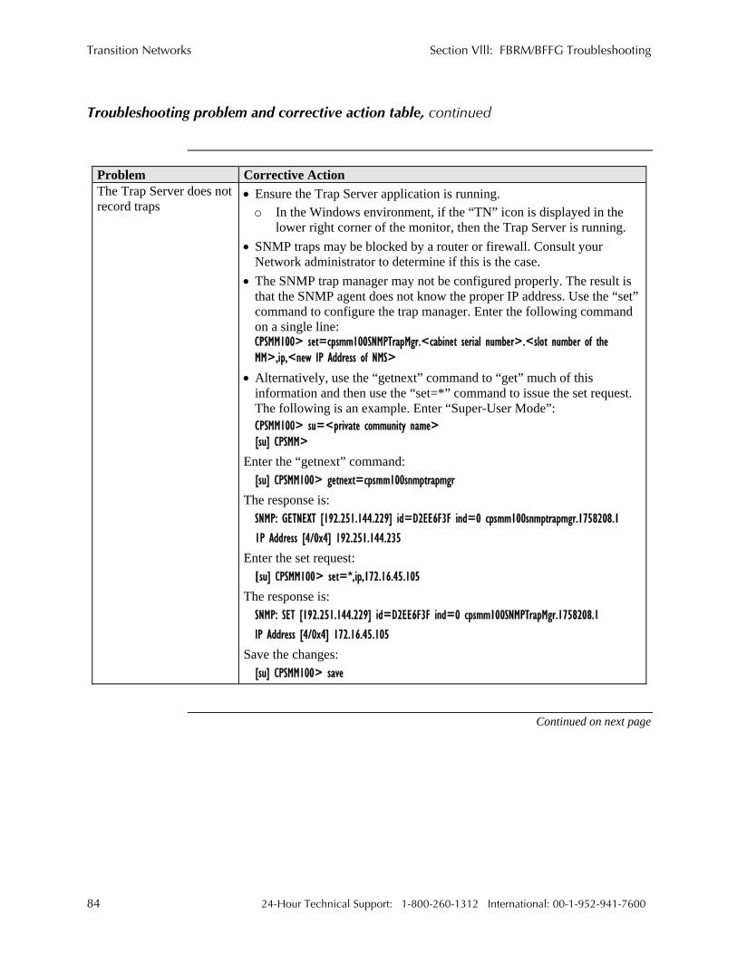
Transition Networks Section Vlll: FBRM/BFFG Troubleshooting
Troubleshooting problem and corrective action table, continued
Problem Corrective Action The Trap Server does not record traps
• Ensure the Trap Server application is running. o In the Windows environment, if the “TN” icon is displayed in the
lower right corner of the monitor, then the Trap Server is running. • SNMP traps may be blocked by a router or firewall. Consult your
Network administrator to determine if this is the case. • The SNMP trap manager may not be configured properly. The result is
that the SNMP agent does not know the proper IP address. Use the “set” command to configure the trap manager. Enter the following command on a single line: CPSMM100> set=cpsmm100SNMPTrapMgr.<cabinet serial number>.<slot number of the MM>,ip,<new IP Address of NMS>
• Alternatively, use the “getnext” command to “get” much of this information and then use the “set=*” command to issue the set request. The following is an example. Enter “Super-User Mode”:
CPSMM100> su=<private community name> [su] CPSMM>
Enter the “getnext” command: [su] CPSMM100> getnext=cpsmm100snmptrapmgr
The response is: SNMP: GETNEXT [192.251.144.229] id=D2EE6F3F ind=0 cpsmm100snmptrapmgr.1758208.1 1P Address [4/0x4] 192.251.144.235
Enter the set request: [su] CPSMM100> set=*,ip,172.16.45.105
The response is: SNMP: SET [192.251.144.229] id=D2EE6F3F ind=0 cpsmm100SNMPTrapMgr.1758208.1 IP Address [4/0x4] 172.16.45.105
Save the changes: [su] CPSMM100> save
Continued on next page
84 24-Hour Technical Support: 1-800-260-1312 International: 00-1-952-941-7600

Section Vlll: FBRM/BFFG Troubleshooting Transition Networks
Troubleshooting problem and corrective action table, continued
Problem Corrective Action The Trap Server does not record traps,(continued)
The response is: FLASH: Saving configuration, please wait up to one minute... Writing Flash (04004500,05E8,00FE0000,00FFFFFE) Erasing . Done Erasing/Verifying Writing [000005E8]
#[0000FFFF] Done Writing
Verifying FLASH: Write complete.
Cannot activate IP-based management
• Are the IP, Gateway, and subnet mask configured correctly? • With DHCP enabled, DHCP could have failed leaving the system with
the old static IP config. Verify the configuration via the USB port. • Make sure IP-based access is not turned OFF in the system. • Contact Technical Support. US/Canada: 1-800-260-1312, International:
00-1-952-941-7600. TLPT and SLDP are not working
• Are the TLPT and SLDP enabled on both systems? Refresh web pages to make sure they are set.
• Check if port binding for TLPT/RFD is set to the active OAM channel. • With 100Base-Fx, make sure “far end fault” is enabled. • Contact Technical Support. US/Canada: 1-800-260-1312, International:
00-1-952-941-7600. OAM session is not active
• If OAM is enabled, check the ports on the local and remote Devices. • Make sure the local Device is in OAM “Active” Mode.
OAM remote Device is detected on local, but cannot configure remote from local
• Make sure the remote peer Device is set to “Passive” Mode. Note: OAM session can be formed between Devices with both set to
Active Mode, but this prevents remote management. The remote Device should be in “Passive” Mode for management.
• Contact Technical Support. US/Canada: 1-800-260-1312, International: 00-1-952-941-7600.
Continued on next page
24-Hour Technical Support: 1-800-260-1312 International: 00-1-952-941-7600 85

Transition Networks Section Vlll: FBRM/BFFG Troubleshooting
Troubleshooting problem and corrective action table, continued
Problem Corrective Action
• If the OAM session is active, the active local peer Device sends configuration information; if the user attempts to go directly to the remote passive peer Device, the configuration will be overwritten by the OAM update from the local active peer. It is advisable to always use the local active peer Device to manage its remote passive peer Device.
Unable to do configuration directly using IP based management on Remote Device • Contact Technical Support. US/Canada: 1-800-260-1312, International:
00-1-952-941-7600. Chassis FBRM/BFFG not recognized by the chassis agent
• Make sure the Point System agent has the latest firmware version for the CFBRM/CBFFG Device. Use the FEATSUPP command to see if the Devices are supported.
• Contact Technical Support. US/Canada: 1-800-260-1312, International: 00-1-952-941-7600.
Chassis FBRM/BFFG is in a single-slot chassis, but the Port 2 comes up in OAM “Passive” Mode with OAM Mode control is set to ‘auto’
• The chassis Devices in single-slot chassis function as a standalone Device.
• Chassis Device needs a Point System management module in a chassis to switch to “Active” Mode, or to set OAM Mode manually.
• Contact Technical Support. US/Canada: 1-800-260-1312, International: 00-1-952-941-7600.
86 24-Hour Technical Support: 1-800-260-1312 International: 00-1-952-941-7600

Section Vlll: FBRM/BFFG Troubleshooting Transition Networks
Intentionally Blank
24-Hour Technical Support: 1-800-260-1312 International: 00-1-952-941-7600 87

Transition Networks
Section lX:
Copper Cable & Fiber Optic Specifications
Introduction This section provides copper and fiber cable specifications.
In this section These are the topics:
Topic See Page Copper cables 89 Fiber optic cables and connectors 90
24-Hour Technical Support: 1-800-260-1312 International: 00-1-952-941-7600 88

Section lX: FBRM/BFFG Cable & Fiber Optic Specifications Transition Networks
Copper cables
Characteristics Cooper cable physical characteristics must meet or exceed IEEE 802.3™
specifications.
Copper cable specification
Category 5: minimum Gauge: 24 to 22 AWG Attenuation: 22.0 dB/100m @ 100 MHz Maximum cable distance: 100 meter (328 ft.) • Straight-through or crossover twisted-pair cable may be used. See Figure 69. • Shielded twisted-pair (STP) or unshielded twisted-pair (UTP) may be used. • Pins 1&2 and 3&6 are the two active pairs in an Ethernet network. • RJ-45 pin-outs on MDI cable: Pin 1 = TD+, Pin 2 = TD-, Pin 3 = RD+, Pin 6 =
RD- • Use only dedicated wire pairs for the active pins. (e.g., blue/white & white/blue, orange/white & white/orange, etc.) • DO NOT use flat or silver satin wire.
Figure 69: MDI Straight Through and MDI-X Crossover Cables
24-Hour Technical Support: 1-800-260-1312 International: 00-1-952-941-7600 89

Transition Networks Section lX: FBRM/BFFG Cable & Fiber Optic Specifications
Fiber optic cable and connector specifications
Fiber cable characteristics
Cable physical characteristics must meet or exceed IEEE 802.3™ specifications.
Parameter Specification Bit Error Rate: <10-9 Single mode fiber: 9 µm Multimode fiber: 62.5/125 µm Multimode fiber: 100/140, 85/140, 50/125 µm
Copper-to-fiber connectors
The following are FBRM10xx-1xx copper-to-fiber connector specifications.
Fiber Optics Specifications
CFBRM1011-100 1300 nm multimode SFBRM1011-100 min: -19.0 dBm max: -14.0 dBm Fiber-optic transmitter power: min: -30.0 dBm max: -14.0 dBm Fiber-optic receiver sensitivity: 11 dB Link budget: CFBRM1013-100 1300 nm multimode SFBRM1013-100 min: -19.0 dBm max: -14.0 dBm Fiber-optic transmitter power: min: -30.0 dBm max: -14.0 dBm Fiber-optic receiver sensitivity: 11 dB Link budget: CFBRM1014-100 1310 nm single mode SFBRM1014-100 min: -15.0 dBm max: -8.0 dBm Fiber-optic transmitter power: min: -31.0 dBm max: -8.0 dBm Fiber-optic receiver sensitivity: 16 dB Link budget:
CFBRM1015-100 (long haul) SFBRM1015-100 (long haul) 1310 nm single mode Fiber-optic transmitter power: min: -8.0 dBm max: -2.0 dBm Fiber-optic receiver sensitivity: min: -34.0 dBm max: -7.0 dBm Link budget: 26 dB
WARNING: Visible and invisible laser radiation when open. Do not stare into the beam or view the beam directly with optical instruments. Failure to observe this warning could result in an eye injury or blindness. WARNING: Use of controls, adjustments or the performance of procedures other than those specified herein may result in hazardous radiation exposure.
Continued on next page
90 24-Hour Technical Support: 1-800-260-1312 International: 00-1-952-941-7600

Section lX: FBRM/BFFG Cable & Fiber Optic Specifications Transition Networks
Fiber optic cable and connector specifications, continued
Copper-to-fiber connectors (continued)
Fiber Optics Specifications CFBRM1016-100 (extra long haul) SFBRM1016-100 (extra long haul) 1310 nm single mode Fiber-optic transmitter power: min: -5.0 dBm max: 0.0 dBm Fiber-optic receiver sensitivity: min: -34.0 dBm max: -7.0 dBm Link budget: 29 dB CFBRM1017-100 (long wave length) SFBRM1017-100 (long wave length) 1550 nm single mode
min: -5.0 dBm max: 0.0 dBm Fiber-optic transmitter power: min: -34.0 dBm max: -7.0 dBm Fiber-optic receiver sensitivity: 29 dB Link budget: CFBRM1035-100 1550 nm single mode SFBRM1035-100 min: -0.0 dBm max: 5.0 dBm Fiber-optic transmitter power: min: -36.0 dBm max: -3.0 dBm Fiber-optic receiver sensitivity: 36 dB Link budget: 1310 nm (TX)/1550 nm (RX) simplex CFBRM1029-100 1550 nm (TX)/1310 nm (RX) simplex CFBRM1029-101 1310 nm (TX)/1550 nm (RX) simplex SFBRM1029-100 1550 nm (TX)/1310 nm (RX) simplex SFBRM1029-101 min: -14.0 dBm max: -8.0 dBm Fiber-optic transmitter power: min: -33.0 dBm max: -3.0 dBm Fiber-optic receiver sensitivity: 19 dB Link budget: 1310 nm (TX)/1550 nm (RX) simplex CFBRM1029-102 1550 nm (TX)/1310 nm (RX) simplex CFBRM1029-103 1310 nm (TX)/1550 nm (RX) simplex SFBRM1029-102 1550 nm (TX)/1310 nm (RX) simplex SFBRM1029-103 min: -8.0 dBm max: -3.0 dBm Fiber-optic transmitter power: min: -33.0 dBm max: -3.0 dBm Fiber-optic receiver sensitivity: 25 dB Link budget:
Note: The fiber optic transmitters on these Devices meet Class I Laser safety
requirements per IEC-825/CDRH standards and comply with 21 CFR1040.10 and 21CFR1040.11.
WARNING: Visible and invisible laser radiation when open. Do not stare into the beam or view the beam directly with optical instruments. Failure to observe this warning could result in an eye injury or blindness. WARNING: Use of controls, adjustments or the performance of procedures other than those specified herein may result in hazardous radiation exposure.
Continued on next page
24-Hour Technical Support: 1-800-260-1312 International: 00-1-952-941-7600 91

Transition Networks Section lX: FBRM/BFFG Cable & Fiber Optic Specifications
Fiber optic cable and connector specifications, continued
Copper-to-Copper-to-fiber connectors with DMI
Fiber Optics Specifications CFBRM1011-110 DMI SFBRM1011-110 DMI 1300 nm multimode Fiber-optic transmitter power: min: -19.0 dBm max: -14.0 dBm Fiber-optic receiver sensitivity: min: -30.0 dBm max: -14.0 dBm Link budget: 11 dB
CFBRM1013-110 DMI 1300 nm multimode SFBRM1013-110 DMI min: -19.0 dBm max: -14.0 dBm Fiber-optic transmitter power: min: -30.0 dBm max: -14.0 dBm Fiber-optic receiver sensitivity: 11 dB Link budget: CFBRM1014-110 DMI 1310 nm single mode SFBRM1014-110 DMI min: -15.0 dBm max: -8.0 dBm Fiber-optic transmitter power: min: -31.0 dBm max: -8.0 dBm Fiber-optic receiver sensitivity: 16 dB Link budget:
CFBRM1015-110 DMI (long haul) SFBRM1015-110 DMI(long haul) 1310 nm single mode
min: -8.0 dBm max: -2.0 dBm Fiber-optic transmitter power: min: -34.0 dBm max: -7.0 dBm Fiber-optic receiver sensitivity: 26 dB Link budget: CFBRM1016-110 DMI
SFBRM1016-110 DMI 1310 nm single mode (extra long haul) min: -5.0 dBm max: 0.0 dBm
min: -34.0 dBm max: -7.0 dBm Fiber-optic transmitter power: 29 dB Fiber-optic receiver sensitivity:
Link budget: CFBRM1017-110 DMI 1550 nm single mode SFBRM1017-110 DMI
(long wave length) min: -5.0 dBm max: 0.0 dBm min: -34.0 dBm max: -7.0 dBm Fiber-optic transmitter power: 29 dB Fiber-optic receiver sensitivity:
Link budget: CFBRM1035-110 DMI 1550 nm single mode SFBRM1035-110 DMI min: -0.0 dBm max: 5.0 dBm Fiber-optic transmitter power: min: -36.0 dBm max: -3.0 dBm Fiber-optic receiver sensitivity: 36 dB Link budget:
Continued on next page
92 24-Hour Technical Support: 1-800-260-1312 International: 00-1-952-941-7600

Section lX: FBRM/BFFG Cable & Fiber Optic Specifications Transition Networks
Fiber optic cable and connector specifications, continued
Copper-to-fiber connectors with DMI (continued)
Fiber Optics Specifications 1310 nm (TX)/1550 nm (RX) simplex CFBRM1029-110 DMI 1550 nm (TX)/1310 nm (RX) simplex CFBRM1029-111 DMI 1310 nm (TX)/1550 nm (RX) simplex SFBRM1029-110 DMI 1550 nm (TX)/1310 nm (RX) simplex SFBRM1029-111 DMI min: -14.0 dBm max: -8.0 dBm Fiber-optic transmitter power: min: -33.0 dBm max: -3.0 dBm Fiber-optic receiver sensitivity: 19 dB Link budget: 1310 nm (TX)/1550 nm (RX) simplex CFBRM1029-112 DMI 1550 nm (TX)/1310 nm (RX) simplex CFBRM1029-113 DMI 1310 nm (TX)/1550 nm (RX) simplex SFBRM1029-112 DMI 1550 nm (TX)/1310 nm (RX) simplex SFBRM1029-113 DMI min: -8.0 dBm max: -3.0 dBm Fiber-optic transmitter power: min: -33.0 dBm max: -3.0 dBm Fiber-optic receiver sensitivity: 25 dB Link budget:
Note: The fiber optic transmitters on these Devices meet Class I Laser safety
requirements per IEC-825/CDRH standards and comply with 21 CFR1040.10 and 21CFR1040.11.
WARNING: Visible and invisible laser radiation when open. Do not stare into the beam or view the beam directly with optical instruments. Failure to observe this warning could result in an eye injury or blindness. WARNING: Use of controls, adjustments or the performance of procedures other than those specified herein may result in hazardous radiation exposure.
Continued on next page
24-Hour Technical Support: 1-800-260-1312 International: 00-1-952-941-7600 93

Transition Networks Section lX: FBRM/BFFG Cable & Fiber Optic Specifications
Fiber optic cable and connector specifications, continued
FBRM fiber-to-fiber Gbit connector
Fiber Optics Port 1 Specification Port 2 Specification CFBRM1313-100 850 nm multimode 1310 nm multimode SFBRM1313-100 min: -10.0 dBm max: -14.0 dBm min: -19.0 dBm max: -14.0 dBm Fiber-optic transmitter power: min: -17.0 dBm max: 0.0 dBm min: -30.0 dBm max: -14.0 dBm Fiber-optic receiver sensitivity: 7 dB 11 dB Link budget:
CFBRM1314-100 SFBRM1314-100 1310 nm multimode 1310 nm single mode Fiber-optic transmitter power: min: -19.0 dBm max: -14.0 dBm min: -13.0 dBm max: -3.0 dBm Fiber-optic receiver sensitivity: min: -30.0 dBm max: -14.0 dBm min: -20.0 dBm max: -3.0 dBm Link budget: 11 dB 7 dB
CFBRM1315-100 1310 nm single mode 1310 nm multimode SFBRM1315-100 min: -5.0 dBm max: 0.0 dBm min: -19.0 dBm max: -14.0 dBm Fiber-optic transmitter power: min: -20.0 dBm max: -3.0 dBm min: -30.0 dBm max: -14.0 dBm Fiber-optic receiver sensitivity: 15 dB 11 dB Link budget: CFBRM1317-100 1550 nm single mode 1310 nm multimode SFBRM1317-100 min: -3.0 dBm max: 2.0 dBm min: -19.0 dBm max: -14.0 dBm Fiber-optic transmitter power: min: -24.0 dBm max: -3.0 dBm min: -30.0 dBm max: -14.0 dBm Fiber-optic receiver sensitivity: 21 dB 11 dB Link budget: 1310 nm (TX)/1490 nm (RX) CFBRM1329-100 1490 nm (TX)/1310 nm (RX) CFBRM1329-101 1310 nm (TX)/1490 nm (RX) SFBRM1329-100 1490 nm (TX)/1310 nm (RX) 1310 nm multimode SFBRM1329-101 min: -8.0 dBm max: 3.0 dBm min: -19.0 dBm max: -14.0 dBm Fiber-optic transmitter power: min: -22.0 dBm max: -3.0 dBm min: -30.0 dBm max: -14.0 dBm Fiber-optic receiver sensitivity: 14 dB 11 dB Link budget: 1310 nm (TX)/1490 nm (RX) CFBRM1329-102 1490 nm (TX)/1310 nm (RX) CFBRM1329-103 1310 nm (TX)/1490 nm (RX) SFBRM1329-102 1490 nm (TX)/1310 nm (RX) 1310 nm multimode SFBRM1329-103 min: -3.0 dBm max: 2.0 dBm min: -19.0 dBm max: -14.0 dBm Fiber-optic transmitter power: min: -23.0 dBm max: -3.0 dBm min: -30.0 dBm max: -14.0 dBm Fiber-optic receiver sensitivity: 20 dB 11 dB Link budget:
Note: The fiber optic transmitters on these Devices meet Class I Laser safety
requirements per IEC-825/CDRH standards and comply with 21 CFR1040.10 and 21CFR1040.11.
Continued on next page
94 24-Hour Technical Support: 1-800-260-1312 International: 00-1-952-941-7600

Section lX: FBRM/BFFG Cable & Fiber Optic Specifications Transition Networks
Fiber optic cable and connector specifications, continued
FBRM fiber-to-fiber Gbit connectors(continued)
Fiber Optics Port 1 Specification Port 2 Specification CFBRM1335-100 1550 nm single mode 1310 nm multimode SFBRM1335-100 min: 0.0 dBm max: 5.0 dBm min: -19.0 dBm max: -14.0 dBm Fiber-optic transmitter power: min: -27.0 dBm max: -3.0 dBm min: -30.0 dBm max: -14.0 dBm Fiber-optic receiver sensitivity: 27 dB 11 dB Link budget:
FBRM fiber-to-fiber Gbit with DMI connectors
Fiber Optics Port 1 Specification Port 2 Specification CFBRM1313-110 DMI 850nm single mode 1300 nm multimode SFBRM1313-110 DMI min: -9.5 dBm max: -4.0 dBm min: -19.0 dBm max: -14.0 dBm Fiber-optic transmitter power: min: -18.0 dBm max: -3.0 dBm min: -30.0 dBm max: -14.0 dBm Fiber-optic receiver sensitivity: 8.5 dB 11 dB Link budget:
CFBRM1314-110 DMI SFBRM1314-110 DMI 1300 nm multimode 1310 nm single mode Fiber-optic transmitter power: min: -19.0 dBm max: -14.0 dBm min: -9.0 dBm max: -3.0 dBm Fiber-optic receiver sensitivity: min: -30.0 dBm max: -14.0 dBm min: -21.0 dBm max: -3.0 dBm Link budget: 11 dB 12 dB
CFBRM1315-110 DMI 1310 nm single mode 1300 nm multimode SFBRM1315-110 DMI min: -5.0 dBm max: 0.0 dBm min: -19.0 dBm max: -14.0 dBm Fiber-optic transmitter power: min: -24.0 dBm max: -3.0 dBm min: -30.0 dBm max: -14.0 dBm Fiber-optic receiver sensitivity: 19 dB 11 dB Link budget: 1310 nm (TX)/1490 nm (RX) CFBRM1329-110 DMI 1490 nm (TX)/1310 nm (RX) CFBRM1329-111 DMI 1310 nm (TX)/1490 nm (RX) SFBRM1329-110 DMI 1490 nm (TX)/1310 nm (RX) 1300 nm multimode SFBRM1329-111 DMI min: -9.0 dBm max: 3.0 dBm min: -19.0 dBm max: -14.0 dBm Fiber-optic transmitter power: min: -20.0 dBm max: -3.0 dBm min: -30.0 dBm max: -14.0 dBm Fiber-optic receiver sensitivity: 11 dB 11 dB Link budget: 1310 nm (TX)/1490 nm (RX) CFBRM1329-112 DMI 1490 nm (TX)/1310 nm (RX) CFBRM1329-113 DMI 1310 nm (TX)/1490 nm (RX) SFBRM1329-112 DMI 1490 nm (TX)/1310 nm (RX) 1300 nm multimode SFBRM1329-113 DMI min: -9.0 dBm max: 3.0 dBm min: -19.0 dBm max: -14.0 dBm Fiber-optic transmitter power: min: -20.0 dBm max: -3.0 dBm min: -30.0 dBm max: -14.0 dBm
11 dB Fiber-optic receiver sensitivity:
11 dB Link budget:
Continued on next page
24-Hour Technical Support: 1-800-260-1312 International: 00-1-952-941-7600 95

Transition Networks Section lX: FBRM/BFFG Cable & Fiber Optic Specifications
Fiber optic cable and connector specifications, continued
Copper-to-fiber connectors
The following are BFFG10x40-100 copper-to-fiber connector specifications.
Fiber Optics Specifications
CBFFG1040-100 Empty Slot SBFFG1040-100
Fiber-optic transmitter power: Fiber-optic receiver sensitivity: Link budget:
Note: The fiber optic transmitters on these Devices meet Class I Laser safety
requirements per IEC-825/CDRH standards and comply with 21 CFR1040.10 and 21CFR1040.11.
WARNING: Visible and invisible laser radiation when open. Do not stare into the beam or view the beam directly with optical instruments. Failure to observe this warning could result in an eye injury or blindness. WARNING: Use of controls, adjustments or the performance of procedures other than those specified herein may result in hazardous radiation exposure.
Continued on next page
96 24-Hour Technical Support: 1-800-260-1312 International: 00-1-952-941-7600

Section lX: FBRM/BFFG Cable & Fiber Optic Specifications Transition Networks
Fiber optic cable and connector specifications, continued
BFFG fiber-to-fiber Gbit connectors
Fiber Optics Port 1 Specification Port 2 Specification CBFFG1313-100 850 nm single mode 1300 nm multimode SBFFG1313-100 min: -10.0 dBm max: -14.0 dBm min: -19.0 dBm max: -14.0 dBm Fiber-optic transmitter power: min: -17.0 dBm max: 0.0 dBm min: -30.0 dBm max: -14.0 dBm Fiber-optic receiver sensitivity: 7 dB 11 dB Link budget: CBFFG1314-100 1310 nm single mode 1300 nm multimode SBFFG1314-100 min: -13.0 dBm max: -3.0 dBm min: -19.0 dBm max: -14.0 dBm Fiber-optic transmitter power: min: -20.0 dBm max: -3.0 dBm min: -30.0 dBm max: -14.0 dBm Fiber-optic receiver sensitivity: 7 dB 11 dB Link budget:
CBFFG1315-100 SBFFG1315-100 1300 nm multimode 1310 nm single mode Fiber-optic transmitter power: min: -19.0 dBm max: -14.0 dBm min: -5.0 dBm max: 0.0 dBm Fiber-optic receiver sensitivity: min: -30.0 dBm max: -14.0 dBm min: -20.0 dBm max: -3.0 dBm Link budget: 11 dB 15 dB
CBFFG1317-100 1310 nm single mode 1300 nm multimode SBFFG1317-100 min: -3.0 dBm max: 2.0 dBm min: -19.0 dBm max: -14.0 dBm Fiber-optic transmitter power: min: -24.0 dBm max: -3.0 dBm min: -30.0 dBm max: -14.0 dBm Fiber-optic receiver sensitivity: 21 dB 11 dB Link budget: 1310 nm (TX)/1490 nm (RX) CBFFG1329-100 1490 nm (TX)/1310 nm (RX) CBFFG1329-101 1310 nm (TX)/1490 nm (RX) SBFFG1329-100 1490 nm (TX)/1310 nm (RX) 1300 nm multimode SBFFG1329-101 min: -8.0 dBm max: 3.0 dBm min: -19.0 dBm max: -14.0 dBm Fiber-optic transmitter power: min: -22.0 dBm max: -3.0 dBm min: -30.0 dBm max: -14.0 dBm Fiber-optic receiver sensitivity: 14 dB 11 dB Link budget: 1310 nm (TX)/1490 nm (RX) CBFFG1329-102 1490 nm (TX)/1310 nm (RX) CBFFG1329-103 1310 nm (TX)/1490 nm (RX) SBFFG1329-102 1490 nm (TX)/1310 nm (RX) 1300 nm multimode SBFFG1329-103 min: -3.0 dBm max: 2.0 dBm min: -19.0 dBm max: -14.0 dBm Fiber-optic transmitter power: min: -23.0 dBm max: -3.0 dBm min: -30.0 dBm max: -14.0 dBm Fiber-optic receiver sensitivity: 20 dB 11 dB Link budget:
Note: The fiber optic transmitters on these Devices meet Class I Laser safety
requirements per IEC-825/CDRH standards and comply with 21 CFR1040.10 and 21CFR1040.11.
Continued on next page
24-Hour Technical Support: 1-800-260-1312 International: 00-1-952-941-7600 97

Transition Networks Section lX: FBRM/BFFG Cable & Fiber Optic Specifications
Fiber optic cable and connector specifications, continued
BFFG fiber-to-fiber Gbit connector (continued)
Fiber Optics Port 1 Specification Port 2 Specification CBFFG1335-100 1310 nm single mode 1300 nm multimode SBFFG1335-100 min: 0.0 dBm max: 5.0 dBm min: -19.0 dBm max: -14.0 dBm Fiber-optic transmitter power: min: -27.0 dBm max: -3.0 dBm min: -30.0 dBm max: -14.0 dBm Fiber-optic receiver sensitivity: 27 dB 11 dB Link budget:
BFFG fiber-to-fiber Gbit with DMI connector
Fiber Optics Port 1 Specification Port 2 Specification CBFFG1313-110 DMI 1310 nm single mode 1300 nm multimode SBFFG1313-110 DMI min: -9.5 dBm max: -4.0 dBm min: -19.0 dBm max: -14.0 dBm Fiber-optic transmitter power: min: -18.0 dBm max: -3.0 dBm min: -30.0 dBm max: -14.0 dBm Fiber-optic receiver sensitivity: 8.5 dB 11 dB Link budget:
CBFFG1314-110 DMI SBFFG1314-110 DMI 1300 nm multimode 1310 nm single mode Fiber-optic transmitter power: min: -19.0 dBm max: -14.0 dBm min: -9 dBm max: -3.0 dBm Fiber-optic receiver sensitivity: min: -30.0 dBm max: -14.0 dBm min: -21.0 dBm max: -3.0 dBm Link budget: 11 dB 12 dB
CBFFG1315-110 DMI 1310 nm single mode 1300 nm multimode SBFFG1315-110 DMI min: -5 dBm max: 0 dBm min: -19.0 dBm max: -14.0 dBm Fiber-optic transmitter power: min: -24.0 dBm max: -3.0 dBm min: -30.0 dBm max: -14.0 dBm Fiber-optic receiver sensitivity: 19 dB 11 dB Link budget: 1310 nm (TX)/1490 nm (RX) CBFFG1329-110 DMI 1490 nm (TX)/1310 nm (RX) CBFFG1329-111 DMI 1310 nm (TX)/1490 nm (RX) SBFFG1329-110 DMI 1490 nm (TX)/1310 nm (RX) 1300 nm multimode SBFFG1329-111 DMI min: -9.0 dBm max: 3.0 dBm min: -19.0 dBm max: -14.0 dBm Fiber-optic transmitter power: min: -20.0 dBm max: -3.0 dBm min: -30.0 dBm max: -14.0 dBm Fiber-optic receiver sensitivity: 11 dB 11 dB Link budget:
Note: The fiber optic transmitters on these Devices meet Class I Laser safety
requirements per IEC-825/CDRH standards and comply with 21 CFR1040.10 and 21CFR1040.11.
WARNING: Visible and invisible laser radiation when open. Do not stare into the beam or view the beam directly with optical instruments. Failure to observe this warning could result in an eye injury or blindness. WARNING: Use of controls, adjustments or the performance of procedures other than those specified herein may result in hazardous radiation exposure.
Continued on next page
98 24-Hour Technical Support: 1-800-260-1312 International: 00-1-952-941-7600

Section lX: FBRM/BFFG Cable & Fiber Optic Specifications Transition Networks
Fiber optic cable and connector specifications, continued
BFFG fiber-to-fiber Gbit with DMI connector (continued)
Fiber Optics Port 1 Specification Port 2 Specification 1310 nm (TX)/1490 nm (RX) CBFFG1329-112 DMI 1490 nm (TX)/1310 nm (RX) CBFFG1329-113 DMI 1310 nm (TX)/1490 nm (RX) SBFFG1329-112 DMI 1490 nm (TX)/1310 nm (RX) SBFFG1329-113 DMI 1300 nm multimode min: -9.0 dBm max: 3.0 dBm Fiber-optic transmitter power: min: -19.0 dBm max: -14.0 dBm min: -20.0 dBm max: -3.0 dBm Fiber-optic receiver sensitivity: min: -30.0 dBm max: -14.0 dBm 11 dB 11 dB Link budget:
Note: The fiber optic transmitters on these Devices meet Class I Laser safety
requirements per IEC-825/CDRH standards and comply with 21 CFR1040.10 and 21CFR1040.11.
WARNING: Visible and invisible laser radiation when open. Do not stare into the beam or view the beam directly with optical instruments. Failure to observe this warning could result in an eye injury or blindness. WARNING: Use of controls, adjustments or the performance of procedures other than those specified herein may result in hazardous radiation exposure.
24-Hour Technical Support: 1-800-260-1312 International: 00-1-952-941-7600 99

Transition Networks Section lX: FBRM/BFFG Cable & Fiber Optic Specifications
Intentionally Blank
100 24-Hour Technical Support: 1-800-260-1312 International: 00-1-952-941-7600

Transition Networks
Section X:
Contact Us, Warranty, & Conformity Information
Introduction This section explains how to contact Transition Networks via Phone, fax, email, and
direct mail. It also explains: • What the warranty covers • Who to contact to return product • How and where to return the product
In this section These are the topics:
24-Hour Technical Support: 1-800-260-1312 International: 00-1-952-941-7600 101
Topic See Page Contact us 102 Conformity declaration 103 Warranty 105 Compliance information 107

Transition Networks Section X: FBRM/BFFG Contact Us, Warranty, & Conformity Information
Contact us
Technical support
Technical Support is available 24 hours a day. United States: 1-800-260-1312 International: 00-1-952-941-7600
Live Web chat Chat live via the Web with a Transition Networks Technical Support Specialist.
Log onto www.transition.com and click the Transition Now link.
Web-based training
Transition Networks provides 12-16 seminars per month via live web-based training. Log onto www.transition.com and click the Learning Center link.
E-Mail Ask a question anytime by sending an e-mail message to our technical support staff:
Address Transition Networks
10900 Red Circle Drive Minnetonka, MN 55343, U.S.A. Telephone: 952-941-7600 Toll free U.S.A & Canada: 800-526-9267 Fax: 952-941-2322
102 24-Hour Technical Support: 1-800-260-1312 International: 00-1-952-941-7600

Section X: FBRM/BFFG Contact Us, Warranty, & Conformity Information Transition Networks
Conformity declaration
Declaration of Conformity
Continued on next page
Name of Mfg: Transitions Networks 6427 City West Parkway, Minneapolis MN 55344 U.S.A.
Model: xFBRM1xxx-1xx and xBFFG1xxx-1xx Media
Part Numbers: CFBRM1011-100, CFBRM1013-100, CFBRM1014-100, CFBRM1015-100, CFBRM1016-100, CFBRM1017-100, CFBRM1035-100, CFBRM1040-100, CFBRM1029-100, CFBRM1029-101, CFBRM1029-102, CFBRM1029-103
CFBRM1011-110, CFBRM1013-110, CFBRM1014-110, CFBRM1015-110, CFBRM1016-110, CFBRM1017-110, CFBRM1035-110, CFBRM1040-110, CFBRM1029-110, CFBRM1029-111, CFBRM1029-112, CFBRM1029-113,
CFBRM1313-100, CFBRM1314-100, CFBRM1315-100, CFBRM1317-100, CFBRM1035-110, CFBRM1040-100, CFBRM1029-100, CFBRM1029-100, CFBRM1029-100, CFBRM1029-100
CFBRM1313-110, CFBRM1314-110, CFBRM1315-110, CFBRM1317-110, CFBRM1035-110, CFBRM1040-110, CFBRM1029-110, CFBRM1029-111, CFBRM1029-112, CFBRM1029-113
SFBRM1011-100, SFBRM1013-100, SFBRM1014-100, SFBRM1015-100, SFBRM1016-100, SFBRM1017-100, SFBRM1035-100, SFBRM1040-100, SFBRM1029-100, SFBRM1029-101, SFBRM1029-102, SFBRM1029-103
SFBRM1011-110, SFBRM1013-110, SFBRM1014-110, SFBRM1015-110, SFBRM1016-110, SFBRM1017-110, SFBRM1035-110, SFBRM1040-110, SFBRM1029-110, SFBRM1029-111, SFBRM1029-112, SFBRM1029-113,
SFBRM1313-100, SFBRM1314-100, SFBRM1315-100, SFBRM1317-100, SFBRM1335-110, SFBRM1340-100, SFBRM1329-100, SFBRM1029-100, SFBRM1329-100, SFBRM1329-100
SFBRM1313-110, CFBRM1314-110, SFBRM1315-110, SFBRM1317-110, CFBRM1335-110, SFBRM1340-110, SFBRM1329-110, CFBRM1329-111, CFBRM1329-112, SFBRM1329-113
CBFFG1013-100, CBFFG1014-100, CBFFG1015-100, CBFFG1017-100, CBFFG1024-100, CBFFG1035-100, CBFFG1040-100, CBFFG1029-100, CBFFG1029-101, CBFFG1029-102, CBFFG1029-103
CBFFG1313-100, CBFFG1314-100, CBFFG1315-100, CBFFG1317-100, CBFFG1335-100, CBFFG1340-100, CBFFG1329-100, CBFFG1329-101, CBFFG1329-102, CBFFG1029-103
CBFFG1313-110, CBFFG1314-110, CBFFG1315-110, CBFFG1317-110, CBFFG1335-110, CBFFG1340-110, CBFFG1329-100, CBFFG1329-111, CBFFG1329-112, CBFFG1029-113
24-Hour Technical Support: 1-800-260-1312 International: 00-1-952-941-7600 103

Transition Networks Section X: FBRM/BFFG Contact Us, Warranty, & Conformity Information
Conformity declaration, continued
SBFFG1313-100, SBFFG1314-100, SBFFG1315-100, SBFFG1317-100, SBFFG1335-100, SBFFG1340-100, SBFFG1329-100, SBFFG1329-101, SBFFG1329-102, SBFFG1029-103
SBFFG1313-110, SBFFG1314-110, SBFFG1315-110, SBFFG1317-110, SBFFG1335-110, SBFFG1340-110, SBFFG1329-110, SBFFG1329-111, CBFFG1329-112, SBFFG1029-113
Regulations: EMC Directive 89/336/EEC
Purpose: To declare that the CFBRM1xxx-1xx, SFBRM1xxx-1xx, CBFFG1xxx-1xx and SBFFG1xxx-1xx Devices to which this declaration refers is in conformance with the following standards:
CISPR22:1993; EN55022:1994+A1:1995+A2:1997 Class A; FCC Part 15 Subpart B; UL1950; 21 CFR Subpart J
I, the undersigned, hereby declare that the equipment specified above conforms to the above Directive(s) and Standard(s).
July, 2008
Steven Anderson, Vice President of Engineering Date
104 24-Hour Technical Support: 1-800-260-1312 International: 00-1-952-941-7600

Section X: FBRM/BFFG Contact Us, Warranty, & Conformity Information Transition Networks
Warranty
Limited lifetime warranty
Effective for products shipped May 1, 1999 and after. Every Transition Networks’ labeled product purchased after May 1, 1999 will be free from defects in material and workmanship for its lifetime. This warranty covers the original user only and is not transferable.
What the warranty does not cover
This warranty does not cover damage from accident, acts of God, neglect, contamination, misuse or abnormal conditions of operation or handling, including over-voltage failures caused by use outside the product's specified rating, or normal wear and tear of mechanical components. If the user is unsure of the proper means of installing or using the equipment, contact Transition Networks' free technical support services.
Establishing original ownership
To establish original ownership and provide date of purchase, please complete and return the registration card accompanying the product or register the product on-line on our product registration page. Transition Networks will at its option: • Repair the defective product to functional specifications at no charge • Replace the product with an equivalent functional product • Refund the purchase price of a defective product
Who to contact for returns
To return a defective product for warranty coverage, contact Transition Networks' technical support department for a return authorization number (RAN). Transition's technical support department can be reached through any of the following means: Technical Support is available 24 hours a day: • Tel: 800-260-1312 x200 or 952-941-7600 x200 • Fax: 952-941-2322 • Email: [email protected] • Live web chat: Transition Now • Voicemail: 800-260-1312, x579 or 952-941-7600, x579 • All messages will be answered within one hour
Continued on next page
24-Hour Technical Support: 1-800-260-1312 International: 00-1-952-941-7600 105

Transition Networks Section X: FBRM/BFFG Contact Us, Warranty, & Conformity Information
Warranty, continued
How and where to send the returns
Send the defective product postage and insurance prepaid to the following address: CSI Material Management Center c/o Transition Networks 6103 Blue Circle Drive Minnetonka, MN 55343, U.S.A. Attn: RETURNS DEPT: Credit Return Authorization (CRA)# or Return Material Authorization (RMA) # ___________ Failure to protect the product during shipping may void this warranty. The return authorization number must be written on the outside of the carton to ensure its acceptance. We cannot accept delivery of any equipment sent to us without a CRA or RMA number.
Customer pays non-compliant return costs
The customer must pay the non-compliant product(s) return transportation cost to Transition Networks for evaluation of said product(s) for repair or replacement. Transition Networks will pay for shipping the repaired or replaced in-warranty product(s) back to the customer (any and all customs charges, tariffs, or/and taxes are the customer's responsibility).
Non-warranty repair costs
Before making any non-warranty repair, Transition Networks requires a $200 charge, plus actual shipping costs to and from the customer. If the repair is greater than $200, an estimate is issued to the customer for authorization before making the repair. If no authorization is obtained, or the product is deemed not repairable, Transition Networks will retain the $200 service charge and return the product to the customer not repaired.
Repaired non-warranty products
Non-warranted products repaired by Transition Networks for a fee will carry a 180-day limited warranty. All warranty claims are subject to the restrictions and conventions set forth by this document. Transition Networks reserves the right to charge for all testing and shipping incurred, if after testing, a return is classified as "No Problem Found."
This warranty is your only remedy
This warranty is your only remedy. No other warranties, such as fitness for a particular purpose, are expressed or implied. Transition Networks is not liable for any special, indirect, incidental or consequential damages or losses, including loss of data, arising from any cause or theory. Authorized resellers are not authorized to extend any different warranty on transition networks' behalf.
106 24-Hour Technical Support: 1-800-260-1312 International: 00-1-952-941-7600

Section X: FBRM/BFFG Contact Us, Warranty, & Conformity Information Transition Networks
Compliance information
Standards CISPR22/EN55022 Class A, CE Mark
FCC Regulations
This equipment has been tested and found to comply with the limits for a Class A digital Device, pursuant to part 15 of the FCC rules. These limits are designed to provide reasonable protection against harmful interference when the equipment is operated in a commercial environment. This equipment generates, uses, and can radiate radio frequency energy and, if not installed and used in accordance with the instruction manual, may cause harmful interference to radio communications. Operation of this equipment in a residential area is likely to cause harmful interference, in which case the user will be required to correct the interference at the user's own expense.
Canadian Regulations
This digital apparatus does not exceed the Class A limits for radio noise from digital apparatus set out on the radio interference regulations of the Canadian Department of Communications. Le présent appareil numérique n'émet pas de bruits radioélectriques dépassant les limites applicables aux appareils numériques de la Class A prescrites dans le Règlement sur le brouillage radioélectrique édicté par le ministère des Communications du Canada.
European Regulations
WARNING: This is a Class A product. In a domestic environment, this product could cause radio interference in which case the user may be required to take adequate measures. Achtung ! Dieses ist ein Gerät der Funkstörgrenzwertklasse A. In Wohnbereichen können bei Betrieb dieses Gerätes Rundfunkstörungen auftreten. In diesem Fäll ist der Benutzer für Gegenmaßnahmen verantwortlich. Attention ! Ceci est un produit de Classe A. Dans un environment domestique, ce produit risque de créer des interférences radioélectriques, il appartiendra alors à l'utilsateur de prende les measures spécifiques appropriées.
Continued on next page
24-Hour Technical Support: 1-800-260-1312 International: 00-1-952-941-7600 107

Transition Networks Section X: FBRM/BFFG Contact Us, Warranty, & Conformity Information
Compliance information, continued
European Regulations, (continued)
In accordance with European Union Directive 2002/96/EC of the European Parliament and of the Council of 27 January 2003, Transition Networks will accept post usage returns of this product for proper disposal. The contact information for this activity can be found in the 'Contact Us' portion of this document.
CAUTION: RJ connectors are NOT INTENDED FOR CONNECTION TO THE PUBLIC TELEPHONE NETWORK. Failure to observe this caution could result in damage to the public telephone network.
Der Anschluss dieses Gerätes an ein öffentlickes Telekommunikationsnetz in den EG-Mitgliedstaaten verstösst gegen die jeweligen einzelstaatlichen Gesetze zur Anwendung der Richtlinie 91/263/EWG zur Angleichung der Rechtsvorschriften der Mitgliedstaaten über Telekommunikationsendeinrichtungen einschliesslich der gegenseitigen Anerkennung ihrer Konformität.
108 24-Hour Technical Support: 1-800-260-1312 International: 00-1-952-941-7600

Transition Networks
Appendix A: FBRM/BFFG Part Numbers
FBRM copper-to-fiber part numbers
Standard models
The models shown in Table 14 perform as described in this manual. The 110 in the model designation means DMI functionality.
Table 14: FBRM10xx-1xx Model Numbers
24-Hour Technical Support: 1-800-260-1312 International: 00-1-952-941-7600 109
Part Number Port 1: Copper Port 2: Fiber 10/100Base-T 100Base-FX
RJ-45 ST, 100Base-FX 1300nm CFBRM1011-100 100m (328ft) MM CFBRM1011-110 DMI
2 km (1.2 miles) SFBRM1011-100 SFBRM1011-110 DMI CFBRM1013-100 RJ-45 SC, 100Base-FX 1300nm
100m (328ft) CFBRM1013-110 DMI MM 2 km (1.2 miles) SFBRM1013-100
SFBRM1013-110 DMI CFBRM1014-100 RJ-45 SC, 100Base-LX10 1310nm
100m (328ft) CFBRM1014-110 DMI SM 10 km (6.2 miles) SFBRM1014-100
SFBRM1014-110 DMI CFBRM1015-100 RJ-45 SC, 100Base-FX 1310nm
100m (328ft) CFBRM1015-110 DMI SM 40 km (24.9 miles) SFBRM1015-100
SFBRM1015-110 DMI (long haul) CFBRM1016-100 RJ-45 SC, 100Base-FX 1310nm
100m (328ft) CFBRM1016-110 DMI SM 60 km (37.3 miles) SFBRM1016-100
SFBRM1016-110 DMI (extra long haul) CFBRM1017-100 RJ-45 SC, 100Base-FX 1550nm
100m (328ft) CFBRM1017-110 DMI SM 80 km (49.7 miles) SFBRM1017-100
SFBRM1017-110 DMI (long wave) CFBRM1035-100 RJ-45 SC, 100Base-FX 1550nm
100m (328ft) CFBRM1035-110 DMI SM 120km (74.6 miles) SFBRM1035-100
SFBRM1035-110 DMI (long wave length)
Continued on next page

Transition Networks Appendix A: FBRM/BFFG Part Numbers
FBRM copper-to-fiber part numbers, continued
Single-fiber model pairs
The models shown in Table 15 are single-fiber and must be installed in pairs.
Table 15: FBRM10xx-1xx Single-Fiber Model Pairs
Part Number Port 1: Copper Port 2: Fiber 10/100Base-T 100Base-FX
CFBRM1029-100** RJ-45 SC, 100Base-FX BX-U 1310 nm 100m (328ft) CFBRM1029-110** DMI TX/1550nm RX
SFBRM1029-100** SM 20 km (12.4 miles) SFBRM1029-110** DMI
RJ-45 SC, 100Base-FX BX-D 1550 nm CFBRM1029-101** 100m (328ft) TX/1310 nm RX CFBRM1029-111** DMI
SM SFBRM1029-101** 20 km (12.4 miles) SFBRM1029-111** DMI
RJ-45 SC, 100Base-FX BX-U 1310 nm CFBRM1029-102*** 100m (328ft) TX/1550nm RX CFBRM1029-112*** DMI
SM SFBRM1029-102*** 40 km (24.9 miles) SFBRM1029-112*** DIM
RJ-45 SC, 100Base-FX BX-D 1550 nm CFBRM1029-103*** 100m (328ft) TX/1310nm RX CFBRM1029-113*** DMI
SM SFBRM1029-103*** 40 km (24.9 miles) SFBRM1029-113*** DMI
BX-D (down stream) BX-U (up stream)
Note: The distances for Port 1 listed in Table 15 are typical maximum distances; the
physical characteristics of the network dictate actual distances.
**FBRM-100 and -101, -110 and -111 Device pairs require installation in the same network, where one is the local Device and the other its remote peer. ***FBRM-102 and -103, -112 and -113 Device pairs require installation in the same network, where one is the local Device and the other its remote peer.
Continued on next page
110 24-Hour Technical Support: 1-800-260-1312 International: 00-1-952-941-7600

Appendix A: FBRM/BFFG Part Numbers Transition Networks
FBRM copper-to-fiber part numbers, continued
The models shown in Table 16 use SFP (small form factor pluggable) Devices sold separately from Transition networks.
SFP models
Table 16: FBRM1040-1xx (SFP Models) Part Number Port 1: Copper 10/100Base-T Port 2: Empty
RJ-45 100m (328ft) CFBRM1040-100 Empty SFP slot* CFBRM1040-110 DMI SFBRM1040-100 SFBRM1040-110 DMI
Note: The distances for Port 1 listed in Table 21 are typical maximum distances; the
physical characteristics of the network dictate actual distances.
*Compatible SFP transceiver Devices for the FBRM1040-1xx Devices are available from Transition Networks (sold separately). See the TN-SFP-xxx series SFP manual # 33308 at www.transiton.com for available options.
24-Hour Technical Support: 1-800-260-1312 International: 00-1-952-941-7600 111

Transition Networks Appendix A: FBRM/BFFG Part Numbers
FBRM fiber-to-fiber part numbers
FBRM Gbit models
The models shown in Table 17 are dual-fiber port models. The 11x in the model designation means DMI functionality.
Table 17: FBRM13xx-1xx Gbit Models
Part Number Port 1: Fiber Port 2: Fiber 100Base-FX 1000Base-SX/LX
CFBRM1313-100 100Base-FX 1300 nm MM SC 2Km (1.2 miles)
SC, 1000Base-SX 850 nm CFBRM1313-110 DMI SFBRM1313-100 SFBRM1313-110 DMI
MM 300/500 m (985/1,640 ft)
CFBRM1314-100 100Base-FX 1300 nm MM SC 2Km (1.2 miles)
SC, 1000Base-LX 1310 nm SM CFBRM1314-110 DMI
SFBRM1314-100 SFBRM1314-110 DMI
10 Km (6.2 miles)
100Base-FX 1300 nm MM SC 2Km (1.2 miles)
SC, 1000Base-LX 1310 nm SM
CFBRM1315-100 CFBRM1315-110 DMI SFBRM1315-100 SFBRM1315-110 DMI
25 km (15.5 miles)
100Base-FX 1300 nm MM SC 2Km (1.2 miles)
SC, 1000Base-LX 1310 nm SM
CFBRM1317-100 CFBRM1317-110 DMI SFBRM1317-100 SFBRM1317-110 DMI
65 km (40.3 miles)
CFBRM1335-100 100Base-FX 1300 nm MM SC, 2 Km (1.2 miles)
SC, 1000Base-LX 1310 nm SM SFBRM1335-110 DMI 120 km (74.6 miles) CFBRM1335-100
SFBRM1335-110 DMI
Continued on next page
112 24-Hour Technical Support: 1-800-260-1312 International: 00-1-952-941-7600

Appendix A: FBRM/BFFG Part Numbers Transition Networks
FBRM fiber-to-fiber part numbers, continued
Single-fiber models
The models shown in Table 18 are single-fiber models and must be installed in pairs.
Table 18: FBRM13xx-1xx Single Fiber Model Pairs
Part Number Port 1: Fiber Port 2: Fiber 100Base-FX 1000Base-SX/LX
CFBRM1329-100* 100Base-FX 1300 nm SC, 1000Base-LX BX-U 1310 nm TX/1490 nm RX MM SC, 2 Km (1.2 miles) CFBRM1329-110* DMI
SFBRM1329-100* SM 20km (12.4 miles) SFBRM1329-110* DMI
100Base-FX 1300 nm SC, 1000Base-LX BX-D 1490nm TX/1310 nm RX
CFBRM1329-101* MM SC, 2 Km (1.2 miles) CFBRM1329-111* DMI
SM SFBRM1329-101* 20 km (12.4 miles) SFBRM1329-111* DMI
R100Base-FX 1300 nm MM SC, 2 Km (1.2 miles)
SC, 100Base-LX BX-U 1310 nm TX/1490 nm RX
CFBRM1329-102** CFBRM1329-112** DMI
SM SFBRM1329-102** 40 km (24.9 miles) SFBRM1329-112** DIM
100Base-FX 1300 nm SC, 100Base-LX BX-D 1490 nm TX/1310 nm RX
CFBRM1329-103** MM SC, 2 Km (1.2 miles) CFBRM1329-113** DMI
SM SFBRM1329-103** 40 km (24.9 miles) SFBRM1329-113** DMI
BX-D (down stream) BX-U (up stream)
*FBRM-100 and -101, -110 and -111 Device pairs require installation in the same network, where one is the local Device and the other its remote peer. **FBRM-102 and -103, -112 and -113 Device pairs require installation in the same network, where one is the local Device and the other its remote peer.
Continued on next page
24-Hour Technical Support: 1-800-260-1312 International: 00-1-952-941-7600 113

Transition Networks Appendix A: FBRM/BFFG Part Numbers
FBRM fiber-to-fiber part numbers, continued
The models shown in Table 19 use SFP (small form factor pluggable) Devices sold separately from Transition Networks.
SFP models
Table 19: FBRM1340-1xx (SFP Models) Part Number Port 1: Copper 10/100Base-T Port 2: Empty
RJ-45 100m (328ft) CFBRM1340-100 Empty SFP slot SFBRM1340-100
Note: The distances for Port 1 listed in Table 19 are typical maximum distances;
the physical characteristics of the network dictate actual distances.
Note: Compatible SFP transceiver Devices for the FBRM1040-1xx Devices are available from Transition Networks (sold separately). See the TN-SFP-xxx series SFP manual # 33308 at www.transiton.com for available options.
114 24-Hour Technical Support: 1-800-260-1312 International: 00-1-952-941-7600

Appendix A: FBRM/BFFG Part Numbers Transition Networks
BFFG copper-to-fiber part numbers
Standard models
The models shown in Table 20 perform as described in this manual.
Table 20: xBFFGxx-1xx Model Numbers
Part Number Port 1: Copper Port 2: Fiber 10/100/1000Base-T 1000Base-X
CBFFG1040-100 RJ-45 Empty Slot 100m (328ft) SBFFG1040-100
Note: The distances for Port 1 listed in Table 20 are typical maximum distances;
the physical characteristics of the network dictate actual distances.
Note: Compatible SFP transceiver Devices for the FBRM1040-1xx Devices are available from Transition Networks (sold separately). See the TN-SFP-xxx series SFP manual # 33308 at www.transiton.com for available options.
Continued on next page
24-Hour Technical Support: 1-800-260-1312 International: 00-1-952-941-7600 115

Transition Networks Appendix A: FBRM/BFFG Part Numbers
BFFG fiber-to-fiber part numbers
Gbit models The models shown in Table 21 perform as described in this manual.
Table 21: BFFG13xx-1xx Gbit Models
Part Number Port 1: Fiber Port 2: Fiber 1000Base-SX 1000Base-SX/LX
CBFFG1313-100 SC, 1000Base-SX 850 nm MM
SC, 1000Base-SX 850 nm MM CBFFG1313-110 DMI
SBFFG1313-100 SBFFG1313-110 DMI
220/550 m (722/1,804 ft)* 220/550 m (722/1,804 ft)
SC, 1000Base-SX 850 nm MM
SC, 1000Base-LX 1310 nm SM
CBFFG1314-100 CBFFG1314-110 DMI SBFFG1314-100 SBFFG1314-110 DMI
220/550 m (722/1,804 ft) * 10 Km (6.2 miles)
SC, 1000Base-SX 850 nm MM
SC, 1000Base-LX 1310 nm SM
CBFFG1315-100 CBFFG1315-110 DMI SBFFG1315-100 SBFFG1315-110 DMI
220/550 m (722/1,804 ft) * 25 km (15.5 miles)
CBFFG1317-100 SC, 1000Base-SX 850 nm MM
SC, 1000Base-LX 1310 nm SM CBFFG1317-110 DMI
SBFFG1317-100 SBFFG1317-110 DMI
220/550 m (722/1,804 ft) * 65 km (40.3 miles)
CBFFG1335-100 SC, 1000Base-SX 850 nm MM
SC, 1000Base-LX 1310 nm SM SBFFG1335-110 DMI
220/550 m (722/1,804 ft) * 120 km (74.6 miles) CBFFG1335-100 SBFFG1335-110 DMI
*220 (722 ft): 62.5/125µ fiber *550 m (1,804 ft): 50/125µ fiber
Continued on next page
116 24-Hour Technical Support: 1-800-260-1312 International: 00-1-952-941-7600

Appendix A: FBRM/BFFG Part Numbers Transition Networks
BFFG fiber-to-fiber part numbers, continued
Single-fiber models
The models shown in Table 22 are single-fiber models and must be installed in pairs.
Table 22: BFFG13xx-1xx Single Fiber Model Pairs
Part Number Port 1: Fiber Port 2: Fiber 1000Base-SX 1000Base-SX/LX
CBFFG1329-100** SC, 1000Base-SX 850 nm MM
SC, 1000Base-LX BX-U 1310 nm TX/1490 nm RX CBFFG1329-110** DMI
220/550 m (722/1,804 ft)* SBFFG1329-100** SM 20km (12.4 miles) SBFFG1329-110** DMI
SC, 1000Base-SX 850 nm MM
SC, 1000Base-LX BX-D 1490 nm TX/1310 nm RX
CBFFG1329-101** CBFFG1329-111** DMI
220/550 m (722/1,804 ft)* SM SBFFG1329-101** 20 km (12.4 miles) SBFFG1329-111** DMI
SC, 1000Base-SX 850 nm MM
SC, 100Base-LX BX-U 1310 nmTX/1490 nm RX SM
CBFFG1329-102*** CBFFG1329-112*** DMI
220/550 m (722/1,804 ft)* SBFFG1329-102*** 40 km (24.9 miles) SBFFG1329-112*** DIM
SC, 1000Base-SX 850 nm MM
SC, 100Base-LX BX-D 1490 nm TX/1310 nm RX SM
CBFFG1329-103*** CBFFG1329-113*** DMI
220/550 m (722/1,804 ft)* SBFFG1329-103*** 40 km (24.9 miles) SBFFG1329-113*** DMI
BX-D (down stream) BX-U (up stream)
*220 (722 ft): 62.5/125µ fiber *550 m (1,804 ft): 50/125µ fiber **BFFG-100 and -101, -110 and -111 Device pairs require installation in the same network, where one is the local Device and the other its remote peer. ***BFFG-102 and -103, -112 and -113 Device pairs require installation in the same network, where one is the local Device and the other its remote peer.
Continued on next page
24-Hour Technical Support: 1-800-260-1312 International: 00-1-952-941-7600 117

Transition Networks Appendix A: FBRM/BFFG Part Numbers
BFFG fiber-to-fiber part numbers, continued
The models shown in Table 23 use SFP (small form factor pluggable) Devices sold separately from Transition Networks.
SFP models
Table 23: BFFG1340-1xx (SFP Models) Port 1: Fiber Part Number Port 2: Empty 1000Base-SX
CBFFG1340-100 SC, 1000Base-SX 850 nm MM Empty SFP slot* 220/500 m (728/1,640 ft) SBFFG1340-100
*Compatible SFP transceiver Devices for the BFFG1340-1xx Devices are available from Transition Networks (sold separately). See the TN-SFP-xxx series SFP manual # 33308 at www.transiton.com for available options.
118 24-Hour Technical Support: 1-800-260-1312 International: 00-1-952-941-7600

Appendix A: FBRM/BFFG Part Numbers Transition Networks
Intentionally Blank
24-Hour Technical Support: 1-800-260-1312 International: 00-1-952-941-7600 119

Transition Networks
Appendix B:
FBRM/BFFG Technical Specification
Specifications, notices, and warnings
For use with Transition Networks’ Models FBRM and BFFG or equivalent.
24-Hour Technical Support: 1-800-260-1312 International: 00-1-952-941-7600 120
Parameter Description IEEE Standards IEEE 802.3-2000
IEEE 802.3ah-2004 clause 57, 58 IEEE 802.1q-2003 IEEE 802.1x-2004 IEEE 802.1D IEEE 802.1P
RFC compliance See Appendix D Regulatory Compliance for Emission EN55022 Class A Regulatory Compliance for Immunity EN55024 Safety Compliance Unit: CE Mark
Wall-Mount Power Supply: UL Approved, UL60950, and CSA Certified
Power Consumption 4 watts MTBF* CFBRM & CBFFG models 141,526 MIL217F2 hours 518,418 Bellcore hours SFBRM & SBFFG models 39,895 MIL217F2 hours
106,056 Bellcore hours Power Source 7.5 to 15.9 VDC – Wall-mount AC Adapter
or Point System Backplane (provided) Max Frame Size 1628 bytes Size (width x height x depth) 3.3 x 1 x 4.75 in (83.8 x 25.4 x 120.65 mm)
Standalone: 4oz (113.4 grams) Weight 0 to 50º C (32 to 113º F) Operating Temperature -25 to 65º C (-13 to 149ºF) Storage Temperature
Altitude 0-10,000 feet 5% to 95% (non-condensing) Operating Humidity
MTBF criteria *MTBF is estimated using the predictability method. This method is based on MIL-
104°F at 40°C ambient temperature, typical enclosure heat rise of 10°C, and nominal operating conditions and parameters. Installation and configuration specific MTBF estimates are available upon request: Contact Technical Support.
Continued on next page

Appendix B: FBRM/BFFG Technical Specifications Transition Networks
Specifications, notices, and warnings, continued
Notices • The information in this user’s guide is subject to change. For the most up-to-date
information on the FBRM/BFFG Devices, see the user’s guide on-line at: www.transition.com.
• Product is certified by the manufacturer to comply with DHHS Rule 21/CFR, Subchapter J applicable at the date of manufacture.
• IMPORTANT Copper based media ports: e.g., Twisted Pair (TP) Ethernet, USB, RS232, RS422, RS485, DS1, DS3, Video Coax, etc., are intended to be connected to intra-building (inside plant) link segments that are not subject to lightening transients or power faults.
CAUTION: Copper-based media ports, e.g., Twisted Pair (TP) Ethernet, USB, RS232, RS422, RS485, DS1, DS3, Video Coax, etc., are NOT to be connected to inter-building (outside plant) link segments that are subject to lightening transients or power faults. Failure to observe this caution could result in damage to equipment.
Warnings WARNING: Visible and invisible laser radiation when open: DO NOT stare into the
beam or view the beam directly with optical instruments. Failure to observe this warning could result in an eye injury or blindness. WARNING: Use of controls, adjustments or the performance of procedures other than those specified herein may result in hazardous radiation exposure. WARNING: If the media Device is an IEEE802.3-2005 Powered Device (PD) capable of receiving power via the Medium Dependent Interface (MDI) leads, the power source, connector, and cabling attached to the barrel power connector must meet the isolation requirement specified in IEEE802.3-2005. Failure to observe this warning could result in an electrical shock.
IMPORTANT The xFBRM/xBFFG Device product family is not compatible with the CPSMM-200
and CPSMM-210 management modules when they are used in a cascaded application. The xFBRM/xBFFG can be installed in the “master” chassis with the CPSMM-200, but they can not be installed in a cascaded chassis using the CPSMM-210. Alternatively, the xFBRM/xBFFG can be used with the CPSMM-120 base management module, which does not support cascading of the chassis.
24-Hour Technical Support: 1-800-260-1312 International: 00-1-952-941-7600 121

Transition Networks
Appendix C:
Device Commands & Descriptions
Command Descriptions arp Displays the arp cache. clear counter Clears counters on all ports or on a specific port. Usage:
clearcounter [port=<portno>] cls Clears the screen. exit Exits the CLI/Telnet session. factory defaults Resets the Device to factory default settings—all current
configurations will be erased. help or ? Help or ?: Displays the available commands.
help <cmd >: Displays the command usage in detail. ifconfig port=<portno> Used to configure port parameters. The port number for
the configured port must be specified. Valid port numbers start at “1.” Usage: ifconfig port=<portno>
[adminstate=<enable|disable] [autoneg=<enable|disable>] [duplex=<full|half>] [speed=<10|100|1000>] [portstring=<"value">(max=64)] [iptraffic=<enable|disable>]
The configurable parameters are as follows: adminstate: The port can be disabled or enabled. autoneg: Enable/disable Auto-Negotiation on this
port. duplex: When Auto-Negotiation is disabled,
Duplex Mode of the port can be set to full/half duplex.
speed: The port speed can be set to 10/100 Mbps when Auto-Negotiation is disabled.
portstring: A unique name can be assigned to each port.
iptraffic: The IP traffic can be enabled/disabled on each port individually.
Continued on next page
24-Hour Technical Support: 1-800-260-1312 International: 00-1-952-941-7600 122

Appendix C: Device Commands & Definitions Transition Networks
Command Description ifoam port=<portno> OAM configuration for the specified port. Usage: ifoam port=<portno>
[oam=enable|disable] [oammode=active|passive] [oamrmtloop=enable|disable]
OAM: OAM can be enabled/disabled. Oammode: OAM Mode can be set to Passive/Active
Mode. Oamrmtloop: OAM loopback can be enabled/disable
on the remote Device peer. netstat Displays all active and passive sockets. ping Pings the host to check if it is reachable using ICMP
requests. ps Displays the system processes. reboot Saves the current configuration and reboots the system. save Saves the current configuration to non-volatile memory. set Sets network settings and system configuration.
Usage: set [dhcp=<enable|disable>] [ip=nn.nn.nn.nn] [netmask=nn.nn.nn.nn] [gateway=nn.nn.nn.nn] [trapmgr=nn.nn.nn.nn] [community=<"value">(max=64)] [groupstring=<"value">(max=64)] [radius=<enable|disable)] [radiusip=nn.nn.nn.nn] [radiussercret=<"value">(max=64)] [username=<"value">(max=64)] [password=<"value">(max=64)] [usb=<enable|disable>] [l3capability=<enable|disable)] [snmpaccess=<enable|disable)] [tftpserver=nn.nn.nn.nn] [tftpfile=<"value">(max=64)] [mgmtvlan=<vlanid>(2-4096)
set autoupg Enable/disable auto upgrade. When enabled, automatically upgrades the firmware. Usage: set autoupg=<enable|disable>. This locks/unlocks firmware upgrades from an active OAM Device peer.
Continued on next page
24-Hour Technical Support: 1-800-260-1312 International: 00-1-952-941-7600 123

Transition Networks Appendix C: Device Commands & Definitions
Command Description set community Sets SNMP community name.
Usage: set community=<name> set dhcp Enables/disables DHCP at boot time. In case DHCP
failed during initialization, retry using the “restart” option. Usage: set dhcp=<enable|disable|restart>
set downloadcfg Download the system configuration from a TFTP Server. Usage: Usage: set downloadcfg=<"filename"> [l3access=<enable|disable>] [ipsetting=<default|nochange> Note: The ‘l3access’ and ‘ipsetting’ are options to turnOFF
IP access once the upgrade is done, and to change the IP address, subnet and gateway to factory defaults.
set forceupg Enable/disable forcing a firmware upgrade of the peer on specified port, automatically. Usage: set forceupg port=<portno>
set gateway Sets gateway address. Usage: set gateway=nn.nn.nn.nn
set groupstring Sets group string for the system. Usage: set groupstring=<"name">(max=64)
set uploadcfg Sets uploading the system configuration to a TFTP Server. Usage: Usage: set uploadcfg=<"filename">
set downloadcfg Sets Downloading the system configuration from a TFTP Server. Usage: Usage: set
set ip Sets IP address. Usage: set ip=nn.nn.nn.nn
set l3capability Enables/disables all layer-3 traffic. Usage: set l3capability=<enable|disable>
set mgmtvlan Sets management VLAN ID for management traffic. Usage: set mgmtvlan=<vlanid>
set niecho Sets the number of echo frames to be sent, and start the non-intrusive echo frame generation on the interface. Usage: set niecho port=<portno> count=<1-100>
set autoupg Enable/disable auto upgrade. When enabled, Auto firmware upgrade be done. Usage: set autoupg=<enable|disable>
set forceupg Enable/disable Forcing Auto firmware upgrade on Peer on specified port Usage: set forceupg port=<portno>
Continued on next page
124 24-Hour Technical Support: 1-800-260-1312 International: 00-1-952-941-7600
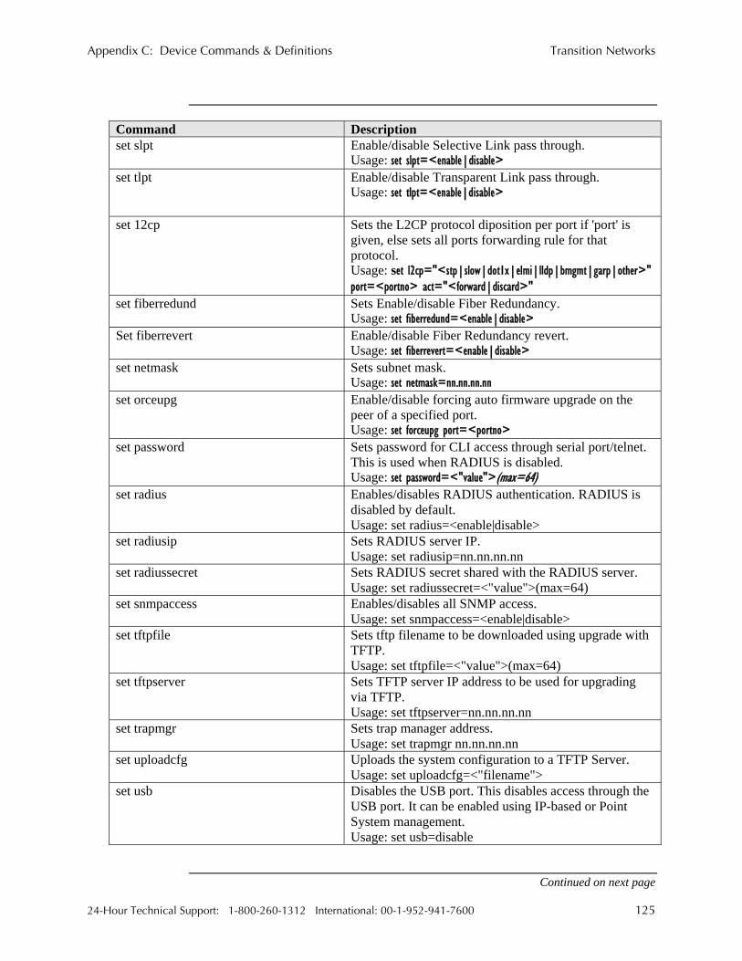
Appendix C: Device Commands & Definitions Transition Networks
Command Description set slpt Enable/disable Selective Link pass through.
Usage: set slpt=<enable|disable> set tlpt Enable/disable Transparent Link pass through.
Usage: set tlpt=<enable|disable>
set 12cp Sets the L2CP protocol diposition per port if 'port' is given, else sets all ports forwarding rule for that protocol. Usage: set l2cp="<stp|slow|dot1x|elmi|lldp|bmgmt|garp|other>" port=<portno> act="<forward|discard>"
set fiberredund Sets Enable/disable Fiber Redundancy. Usage: set fiberredund=<enable|disable>
Set fiberrevert Enable/disable Fiber Redundancy revert. Usage: set fiberrevert=<enable|disable>
set netmask Sets subnet mask. Usage: set netmask=nn.nn.nn.nn
set orceupg Enable/disable forcing auto firmware upgrade on the peer of a specified port. Usage: set forceupg port=<portno>
set password Sets password for CLI access through serial port/telnet. This is used when RADIUS is disabled. Usage: set password=<"value">(max=64)
set radius Enables/disables RADIUS authentication. RADIUS is disabled by default. Usage: set radius=<enable|disable>
set radiusip Sets RADIUS server IP. Usage: set radiusip=nn.nn.nn.nn
set radiussecret Sets RADIUS secret shared with the RADIUS server. Usage: set radiussecret=<"value">(max=64)
set snmpaccess Enables/disables all SNMP access. Usage: set snmpaccess=<enable|disable>
set tftpfile Sets tftp filename to be downloaded using upgrade with TFTP. Usage: set tftpfile=<"value">(max=64)
set tftpserver Sets TFTP server IP address to be used for upgrading via TFTP. Usage: set tftpserver=nn.nn.nn.nn
set trapmgr Sets trap manager address. Usage: set trapmgr nn.nn.nn.nn
set uploadcfg Uploads the system configuration to a TFTP Server. Usage: set uploadcfg=<"filename">
set usb Disables the USB port. This disables access through the USB port. It can be enabled using IP-based or Point System management. Usage: set usb=disable
Continued on next page
24-Hour Technical Support: 1-800-260-1312 International: 00-1-952-941-7600 125

Transition Networks Appendix C: Device Commands & Definitions
Command Description set username Sets username for CLI access through serial port/telnet.
This username is used when RADIUS is disabled. Usage: set username=<"value">(max=64)
show Displays all the current configurations at the system level, including installed firmware revisions, network configurations, system uptime, etc.
show version Shows current version of the firmware build information.
Show redundancy Shows fiber redundancy settings. show ifcabletest Performs cable tests and displays the cable status for all
or a specified port. Usage: show ifcabletest port=<all | port no>
show ifconfig Displays port configurations, including speed, duplex, and IP access for a specified port, or all ports. Usage: show ifconfig [port=<all | port no>]
show ifoam Displays OAM configuration and status for all or a specified port. Usage: show ifoam [port=<all | port no>]
show ifrmonstats Displays RMON statistics for all or a specified port. Usage: show ifrmonstats [port=<all | port no>]
show ifstats Displays port statistics for all or a specified port. Usage: show ifstats [port=<all | port no>]
show oamloopback Displays OAM Loopback status for all or a specified port. Usage: show oamloopback [port=<all | port no>]
show niecho Displays Non-intrusive echo generation status for all or specified port Usage: show niecho [port=<all | port no>]
show 12cp is (L2cp) Displays L2CP disposition for all or specified port Usage: show l2cp [port=<all | port no>]
show oampeer Displays OAM peer information for all or a specified port. Usage: show oamloopback [port=<all | port no>]
show oamstatistics Displays OAM PDU statistics for all or a specified port. Usage: show oamstatistics [port=<all | port no>]
Continued on next page
126 24-Hour Technical Support: 1-800-260-1312 International: 00-1-952-941-7600

Appendix C: Device Commands & Definitions Transition Networks
Command Description snmpget SNMP GET on the OID is performed try "snmpget
help" for more information. Usage: snmpget [oid=1.2.3.4 | variable=<leaf var | tableEntry.x.y>]
• If the ‘oid’ option is used, the indices should be present for table variables and '0' for leaf variables.
• If the 'variable' option is used, the leaf variables can be named as is, the table variables have the following format <tableentry>.index1.index2
Ex: snmpget variable=sysUpTime snmpget variable=ifEntry.<col>.<ifNumber>
snmpgetn SNMP get-next on the OID is performed if there is no OID specified. It uses OID from the last SNMP query, try "snmpgetn help" for more information. Usage: snmpgetn [oid=1.2.3.4 | variable=<leaf var|tableEntry.x.y>]
• If the 'oid' option is used, the indices should be present for table variables and '0' for leaf variables.
• If the 'variable' option is used, the leaf variables can be named as is, the table variables have the following format <tableentry>.index1.index2.
Ex: snmpgetn variable=sysContact snmpgetn variable=ifEntry ifEntry.<col>.<ifNumber>
snmpset SNMP SET on the OID is performed with the value, try "snmpset help" for more information. Usage: snmpset oid=<x.y.z> type=<STR | IP | INT> value=<value>
• Strings must be enclosed in quotes (“”). If the ‘oid’ option is used, the indices should be present for table variables and ‘0’ for leaf variables.
• If the 'variable' option is used, the leaf variables can be named as is, the table variables have the following format <tableentry>.index1.index2
Ex: snmpset variable=sysContact type=STR value="[email protected]"
snmpset variable=ifEntry.2.<ifNumber> type=STR value="Interface 1."
Continued on next page
24-Hour Technical Support: 1-800-260-1312 International: 00-1-952-941-7600 127

Transition Networks Appendix C: Device Commands & Definitions
Command Description snmpwalk SNMP walk of the entire MIB tree if no options are
specified or from OID from the last query if 'continue' is specified. Usage: snmpwalk <continue>
sys The system group variables of MIB-II can be configured using the ‘sys’ command. The system contact, name, and location can be set. Usage: sys
[contact=<"value">(max=64)] [name=<"value">(max=64)] [location=<"value">(max=64)]
tftpupgrade Upgrades the firmware running on the Device using TFTP protocol. The tftp server IP and tftp filename should be configured using the “set” command, or can be given as arguments to this command.
Usage: tftpupgrade erver=nn.nn.nn.nn filename=<"filename"> xmodemupgrade Upgrades the firmware running on the Device, using
XModem protocol. The command invokes the bootloader and start an XModem transfer to upgrade the firmware.
128 24-Hour Technical Support: 1-800-260-1312 International: 00-1-952-941-7600

Transition Networks
Appendix D:
IP-Based and Chassis Management Parameters
IP- and chassis-based management
The chassis Device version of the Devices plugs into a Point System chassis to provide management through the I2C interface: SNMP and web-based management through the MMU. SNMP management is based on the Transition Networks enterprise MIBs. The chassis-based management (via the MMU) provides a subset of the IP-based management via ports. Tables 26, 27, and 28 present IP- and chassis-based configuration management parameters. Note: The mark means available; a blank cell means not available.
Table 24: System Configuration Parameters
24-Hour Technical Support: 1-800-260-1312 International: 00-1-952-941-7600 129
Parameter IP based Chassis Description The currently installed version of the
Bootloader. BootLoader Version Config Match Configuration management match. Default Gateway The gateway in a network that will be
used to access another network if a gateway is not specified for use.
DHCP DHCP (Dynamic Host Configuration Protocol) Enable/disable DHCP to obtain IP, subnet mask, and gateway data upon reboot.
Firmware Version The currently installed version of the firmware.
IP Address IP address of the Device. IP Traffic Access Enable/disable IP Traffic to the Device. MAC Address The MAC address is a unique identifier
attached to most network adapter NICs. It is a number that acts like the name for a particular network adapter.
Management VLAN ID
Thru CLI only
When 802.1q is enabled, the administrator can configure VLAN IDs used for all management traffic to and from the Device via the CLI or through the chassis management agent.
Marketing Revision
Marketing revision.
Enable/disable RADIUS authentication. When enabled, the user is authenticated during login at the CLI or web interface.
RADIUS Authentication
Continued on next page

Transition Networks Appendix D: IP-Based and Chassis Management Parameters
Table 26: System Configuration Parameters (continued)
Parameter IP based Chassis Description RADIUS Retry Retries after a network failure. RADIUS Secret The shared secret between this Device
and the RADIUS server. The IP address of the RADIUS server is
used to get user information during authentication.
RADIUS Server Address
RADIUS timeout Timeout for each attempt to contact the server.
Serial Access Enable/disable USB port access. Serial Number Serial number of the chassis that the
Device is installed. SNMP Access Enable/disable SNMP management. SNMP Trap Mgr SNMP trap manager IP address. Subnet Mask Determines where the network number in
an IP address ends and the node number in an IP address begins.
TFTP Filename The filename used to upgrade, using TFTP (local Device only).
TFTP server IP address to use for firmware upgrades (local Device only).
TFTP Server Address TFTP upgrade Initiates TFTP firmware upgrades (local
Device only). Enable/disable TLPT. TLPT causes the
loss of link on one side of a Device to be passed through to the other side so that the upstream Device can see fault conditions that would otherwise be hidden by Devices.
Transparent Link Pass-Through
Note: TLPT requires Auto-Negotiation to be enabled on the twisted pair interface.
Continued on next page
130 24-Hour Technical Support: 1-800-260-1312 International: 00-1-952-941-7600

Appendix D: IP-Based and Chassis Management Parameters Transition Networks
Table 25: Media Device Parameters Parameter IP based Chassis Description
The aging time (in seconds) for entries in the forwarding database of the switch.
Aging Time (Forwarding DB)
Factory Defaults This erases all configuration data and sets the Device to factory default settings.
Flush FDB Flushes all forwarding database entries. Flush VLAN DB Flushes all VLAN database entries. Histogram Mode This determines what frame types are
accounted for in the port counters. The choices are “count only RX frames” or TX frames or both.
IEEE 802.1p priority mapping. The value in this field is used as the priority of the frame if it has the tag ‘n.’
IEEE Priority class 'n' [0-7]
IP priority remapping. The value in this field is used as the priority of the frame if its IP TOS bits have a traffic class value between 0x00 and 0xE0, with 1 --> 0x00, 2 --> 0x04,...64 --> 0xE0.
IP Traffic class 'n' [1-64]
Reset Counters Resets all port counters to zero.
Table 26: Port Configuration Parameters Parameter IP based Chassis Description
Admin Status The administrative status of the interface should be enabled for normal operation. When the admin state is disabled, the port goes into listening mode, the link will be UP, but the interface does not forward frames.
Advt 10 Full Duplex
Enable/disable advertising full duplex and 10Mbps capability on this port.
Advt 10 Half Duplex
Enable/disable advertising half duplex and 10Mbps capability on this port.
Advt 100 Full Duplex
Enable/disable advertising full duplex and 100Mbps capability on this port.
Enable/disable advertising half duplex and 100Mbps capability on this port.
Advt 100 Half Duplex
Enable/disable advertising Advt Pause capability
Pause capability on the interface.
Continued on next page
24-Hour Technical Support: 1-800-260-1312 International: 00-1-952-941-7600 131

Transition Networks Appendix D: IP-Based and Chassis Management Parameters
Table 28: Port Configuration Parameters (continued)
Parameter IP based Chassis Description Autocross When enabled, detects and configures the
twisted pair port on the Device to the correct MDI or MDI-X configuration automatically.
Auto-Negotiation Allows Devices to configure themselves automatically to achieve the best possible mode of operation over a link.
Connector Type Connector type of the port. When enabled, the DA (destination
address) of the frame is used to get a hit on the address database with an entry matching the DA when priority override is enabled. The priority specified in the entry is the new priority of the frame. The DA override has a higher priority than the default priority of the frame, IP TOS, IEEE Priority tags, VTU override, and SA override. Normal frame priority processing occurs when disabled.
DA Priority Override
Default Forward When enabled, multicast frames with unknown destination addresses are allowed to ‘egress’ this port if VLAN is enabled. The VLAN setting also allows this port to ‘egress.’
Default Priority The default priority of the frames entering the port when no other priorities are assigned and enabled.
Default VLAN ID When IEEE 802.1q is enabled, the default VID is used as the IEEE tagged VLAN ID to un-tag or priority tag frames when they ‘egress of this port.
Description String Group string for this port with the maximum length of 64 characters.
Continued on next page
132 24-Hour Technical Support: 1-800-260-1312 International: 00-1-952-941-7600

Appendix D: IP-Based and Chassis Management Parameters Transition Networks
Table 28: Port Configuration Parameters (continued)
Parameter IP based Chassis Description Discard Tagged When enabled, all non-management
frames processed as tagged are discarded. If double tagging is enabled, then this check is performed after Ingress double tag removal. Frames with priority and VLAN of “0” are considered tagged.
Discard Untagged When enabled, all non-management frames processed as untagged are discarded. If double tagging is enabled, then this check is performed after Ingress double tag removal. Frames with priority and VLAN of “0” are considered tagged.
Discard Untagged When enabled, all non-management frames processed as untagged are discarded. If double tagging is enabled, then this check is performed after ‘ingress’ double tag removal. Frames with priority and VLAN of “0” are considered tagged.
Double Tagging This enables ‘ingress’ double-tagging. It is a way to isolate one VLAN from another VLAN hierarchically. When enabled, also enables ‘egress’ double tagging. In this mode, the Ingress port removes the first IEEE 802.3ac tag that appears after the source address. If a frame is untagged, it is not modified. If it is single tagged it is removed; if it is double tagged, the first tag is removed.
The Duplex Modeof the port (half/full). Duplex Egress Monitor
Port When enabled, all ‘egress’ frames that
come from this port are sent to the ‘egress’ monitor destination port (sfbrm100SwEgressMonPort).
Continued on next page
24-Hour Technical Support: 1-800-260-1312 International: 00-1-952-941-7600 133

Transition Networks Appendix D: IP-Based and Chassis Management Parameters
Table 28: Port Configuration Parameters (continued)
Parameter IP based Chassis Description Egress Rate Controls the effective port transmission
rates. The rate limit is provided as a list of pre-defined values: . noLimit(1) . rate64K(2) . rate96K(3) . rate128K(4) . rate160K(5) . rate192K(6) . rate224K(7) . rate256K(8) . rate320K(9) . rate384K(10) . rate512K(11) . rate768K(12) . rate1M(13) . rate1_2M(14) . rate1_5M(15) . rate2M(16) . rate3M(17) . rate4M(18) . rate5M(19) . rate8M(20) . rate10M(21) . rate20M(22) . rate30M(23) . rate40M(24) . rate60M(25) . rate80M(26)
Far-End Fault Indication
Far-End Fault (FEF) is a troubleshooting feature on the 100Base-TX port
Force Def VLAN ID
When enabled, forces all ‘ingress’ frames with IEEE 802.3ac tags to have replacement VLAN IDs in the frame with the port's default VID. This is valid only if IEEE 802.1q is enabled.
Continued on next page
134 24-Hour Technical Support: 1-800-260-1312 International: 00-1-952-941-7600

Appendix D: IP-Based and Chassis Management Parameters Transition Networks
Table 28: Port Configuration Parameters (continued)
Parameter IP based Chassis Description Forward Unknown When enabled, unicast frames with
unknown destination addresses are allowed to ‘egress’ this port if VLAN is enabled. The VLAN setting also allows this port to ‘egress.’
The priority remapping for frames that ‘ingress’ this port. The IEEE tagged frames with priority ‘n’ get this new remapped priority inside the switch; also if it egresses this port as tagged, the priority is set in the tag.
IEEE Priority class ‘n’ [0-7]
IGMP Snoop This enables IGMP frame forwarding to the CPU. IGMP is not supported in the present release.
Ignore Loopback This corresponds to the EFM OAM MIB. It decides whether the OAM loopback on this port should be ignored.
Ignore Wrong Data This is related to the Port Lock. Enabling this parameter will stop source-address violations caused by Port Lock.
Ingress Limit mode This determines what kinds of frames are limited and counted against ‘ingress’ limiting. Frames not limited by this setting are not counted against the limit.
When enabled, all ‘ingress’ frames are sent to the ‘ingress’ monitor destination port (sfbrm100SwIngressMonPort).
Ingress Monitor Port
IP Traffic When disabled, all IP traffic through this port to the CPU is restricted.
Speed and duplex capabilities of the Link Partner.
Link Partner Autoneg ability
Link Partner Pause ability
Pause frame capabilities of the Link Partner.
Link Status The link status of the port.
Continued on next page
24-Hour Technical Support: 1-800-260-1312 International: 00-1-952-941-7600 135

Transition Networks Appendix D: IP-Based and Chassis Management Parameters
Table 28: Port Configuration Parameters (continued)
Parameter IP based Chassis Description OAM Mode
Control This determines how the OAM Modefor ports is configured (manual/auto): • In auto mode, the port defaults to active
if in a chassis; passive if a standalone. • In manual mode, the user can choose
the OAM mode, using the EFM HUB MIB under the TN private MIB tree.
OAM State Enable/disable IEEE 802.1ah OAM management on this port.
Port Index The index of the port in sfbrm100PortTable.
Port Lock IEEE 802.1x MAC authentication. All non-management frames received on this port are discarded if the source address is not in the learned-address database; this could cause continuous MAC address violation. To prevent this, an entry with all port vectors as ‘0’ can be added to the address database. This disables learning new source addresses.
Continued on next page
136 24-Hour Technical Support: 1-800-260-1312 International: 00-1-952-941-7600

Appendix D: IP-Based and Chassis Management Parameters Transition Networks
Table 28: Port Configuration Parameters (continued)
Parameter IP based Chassis Description Pri0 Ingress Rate Rate limit for Priority “0” frames. The
rate limit is provided as a list of pre-defined values: . noLimit(1) . rate64K(2) . rate96K(3) . rate128K(4) . rate160K(5) . rate192K(6) . rate224K(7) . rate256K(8) . rate320K(9) . rate384K(10) . rate512K(11) . rate768K(12) . rate1M(13) . rate1_2M(14) . rate1_5M(15) . rate2M(16) . rate3M(17) . rate4M(18) . rate5M(19) . rate8M(20) . rate10M(21) . rate20M(22) . rate30M(23) . rate40M(24) . rate60M(25) . rate80M(26)
Pri1 Ingress Rate Control
Rate limit for Priority “1” frames to be the same or twice that of the Priority “0” frames.
Pri2 Ingress Rate Control
Rate limit for Priority “2” frames to be the same or twice that of the Priority “1” frames.
Continued on next page
24-Hour Technical Support: 1-800-260-1312 International: 00-1-952-941-7600 137

Transition Networks Appendix D: IP-Based and Chassis Management Parameters
Table 28: Port Configuration Parameters (continued)
Parameter IP based Chassis Description Pri3 Ingress Rate
Control Rate limit for Priority “3” frames to be the same or twice that of the Priority “2” frames.
Remote Loopback Enable/disable OAM loopback on the remote.
Reset Port Counters
Resets the port counters.
SA Priority Override
When enabled, the source address of the frame is checked against the address database entry with the matching source address with priority override enabled. When there is a match, the fame priority is the one found in the entry. The source address priority override has a higher priority than the default frame priority, IP TC, IEEE priorities, and the VLAN priority override values. Normal frame priority processing occurs when disabled.
Speed The speed in Mbps for this interface. It is the resolved speed when Auto-Negotiation is enabled or the manually set the value when Auto-Negotiation is disabled.
Use Both Traffic class
When a frame has an IEEE 802.ac tag and an IP TOS, then this depends on which priority is chosen, IP TOS or IEEE tag when both sfbrm100PortUseIPTC and sfbrm100PortUseTagTC are enabled.
Use IP Traffic class
This enables the IP Traffic class priority if present. If disabled, the TOS bits are ignored.
Use Tag Traffic class
This enables the IEEE 802.1p priority if the frame is IEEE 802.3ac tagged, or else it is ignored even if the tag is present.
Continued on next page
138 24-Hour Technical Support: 1-800-260-1312 International: 00-1-952-941-7600

Appendix D: IP-Based and Chassis Management Parameters Transition Networks
Table 28: Port Configuration Parameters (continued)
Parameter IP based Chassis Description Virtual Cable Test The virtual cable test determines the
quality of the cable, connectors, and terminations. Problems such as opens, shorts, and cable impendence mismatch can be diagnosed with this test.
VLAN Status 802.1q VLAN can be disabled or enabled along with setting the following options: Secure: The VLAN ID must be contained in the VLAN database (Db) and the ‘ingress’ port must be a member of the VLAN or else it will be discarded. Check: The VLAN ID must be contained in the VLAN Db or the frame will be discarded. Fallback: The frames are not discarded if their VLAN ID is not in the VLAN Db. In all the above cases, the frames are allowed to exit ports that are members of the frame's VLAN, including the source port's VLAN table (sfbrm100PortBasedVLANTbl). Also, frames that do not have a VLAN ID in the Db can exit only ports in the VLAN table. Disabled: 802.1q is disabled.
VLAN Table This is a bitmap that restricts the output ports that this input port can send frames to. To send frames through port ‘2,’ bit ‘2’ of this value must be set to ‘1.’
VLAN Tunnel When enabled, frames that have a source address in the forwarding database are allowed to bypass Port-based VLAN, IEEE 802.1q VLAN and trunk masking.
Continued on next page
24-Hour Technical Support: 1-800-260-1312 International: 00-1-952-941-7600 139

Transition Networks Appendix D: IP-Based and Chassis Management Parameters
Table 28: Port Configuration Parameters (continued)
Parameter IP based Chassis Description VTU Priority
Override When enabled, the port checks the frames
for VLAN IDs that have the VTU Priority override bit set in the VLAN database. It then replaces the priority of the frames with the priority specified in the VLAN entry, which has a higher priority than the default of the frame and IP/IEEE priorities. Normal frame priority processing occurs when disabled.
Static MAC and VLAN tables
The static MAC and VLAN tables are supported only through IP-based management and not through chassis-based management. The chassis supports RMON MIB counters only on ports. The IP-based management supports public MIB counters such as RMON, IFmib. Ether-like MIB, EFM OAM HUB MIB, and port counters directly from the switch.
Note: The MIBs used by the chassis agent for the FBRM/BFFG Device and the
MIB used by IP-based management are different. The chassis agent does not support the EFM hub MIB. If the remote Device
is OAM capable, but not a FBRM/BFFG Device from Transition Networks, the EFM hub MIB will be queried for OAM status.
140 24-Hour Technical Support: 1-800-260-1312 International: 00-1-952-941-7600

Transition Networks
Appendix E:
Request for Comment (RFC) Compliance
RFC compliance
The following is a list of RFC compliances.
[IP] Postel, J. "Internet Protocol DARPA Internet Program Protocol Specification", RFC 791, USC Information Sciences Institute, September 1981.
[ICMP] J. Postel “Internet Control Message Protocol. RFC 792, September 1981.
[ARP] Plummer, David C., "An Ethernet Address Resolution Protocol", RFC 826. Symbolics Inc., November 1982.
[UDP] Postel, J., "Use Datagram Protocol", RFC 768. USC Information Sciences Institute, August 28, 1980.
[TCP] Postel, J., "Transmission Control Protocol DARPA Internet Program Protocol Specification", RFC 793. USC Information Sciences Institute, September 1981.
[950] Mogul, J. and Postel, J., "Internet Standard Subnetting Procedure", RFC 950. Network Working Group, August 1985.
[1122] Braden, R., "Requirements for Internet Hosts - Communications Layers", RFC 1122. Internet Engineering Task Force, October 1989.
[1123] Braden, R., "Requirements for Internet Hosts - Application and Support", RFC 1123. Internet Engineering Task Force, October 1989.
[DHCP] Droms, R., "Dynamic Host Configuration Protocol", RFC 2131. Bucknell University, March 1997.
[HTTP] Fielding, R. et al, "Hypertext Transfer Protocol - HTTP/1.1", RFC 2616. Network Working Group, June 1999.
[2617]Franks, J. et al, "HTTP Authentication: Basic and Digest Access Authentication", RFC 2617. Network Working Group, June 1999.
[2396]Berners-Lee, T. et al, "Uniform Resource Identifiers (URI): Generic Syntax", RFC 2396. MIT, August 1998. [Telnet] Postel, J. and Reynolds, J., "Telnet Protocol Specification", RFC 854. USC Information Sciences Institute, May 1983.
Continued on next page
24-Hour Technical Support: 1-800-260-1312 International: 00-1-952-941-7600 141

Transition Networks Appendix E: Request for Comment (RFC) Compliance
RFC compliance (continued)
[TFTP] Sollins, K., "The TFTP Protocol (Revision 2)", RFC 1350. MIT, July 1992. [SMTP] Klensin, J. ed., "Simple Mail Transfer Protocol", RFC 2821. AT&T Laboratories, April 2001. [SNMP] Case, J. et al, "A Simple Network Management Protocol (SNMP)", RFC 1157. [1213] Management Information Base for Network Management of TCP/IP-based internets: MIB-II [1493] Definitions of Managed Objects for Bridges. RFC 1493 [2674] Definitions of Managed Objects for Bridges with Traffic Classes, Multicast Filtering and Virtual LAN Extensions. RFC 2674 [2819] Remote Network Monitoring Management Information Base. RFC 2819 [2863] The Interfaces Group MIB. K. McCloghrie, F. Kastenholz. June 2000, RFC 2863 [3635] Definitions of Managed Objects for the Ethernet-like Interface Types. RFC 3635
142 24-Hour Technical Support: 1-800-260-1312 International: 00-1-952-941-7600

Transition Networks
Index product.................................................................62 3-Port Switch..See Redundant SFBRM SFP, 3-Port
Switch Fiber Optics characteristics ......................................................92 Auto Link Restore .................................................70 xBFFG13xx Gbit .................................................99 AutoCross xFBRM Gbit DMI ...............................................97
description ...........................................................62 xFBRM10xx ........................................................92 Auto-Negotiation xFBRM13xx ........................................................96
description ...........................................................63 Firmware Upgrade Bandwith Allocation adimin intervention..............................................81
description ...........................................................63 bootloader description .......................................................65 Bootloader
bootloader CLI.....................................................81 CLI access ...........................................................82 description ...........................................................62 firmware upgrade.................................................81 failures .................................................................81 help screen ...........................................................82 via OAM..............................................................81 Chassis via TFTP..............................................................80 management module unit (MMU) .........................4 via Xmodem ........................................................78
COM Port IEEE 802.3ah OAM configuration........................................................29 alternate loop back...............................................67 properties .............................................................31 last gasp/OAM (operation administration and
maintenance) ...................................................66 selecting...............................................................30 Commands and Descriptions ..............................124 last gasp/OAM dying gasp...................................66 Congestion Reduction organization specific PDUs .................................68
remote loop back .................................................67 description ...........................................................64 In-Band Management..............................................2 Connecting
copper cables .......................................................21 Installing power adapter (standalone model).......................22 chassis card..........................................................18
Copper Cables copper cables .......................................................20 standalone devices ...............................................19 characteristics ......................................................91 USB driver...........................................................25 Default
IP Configuration factory IP config ............................................32, 35 default ............................................................32, 35 IP-based (web) password.....................................43 DHCP ..................................................................36 telnet password (directly to device) .....................40 USB CLI..............................................................35 USB password (CLI access) ................................33 web-based ............................................................46 Device Configurations Options
LED chassis/standalone devices...................................77 status ..............................................................74, 75 DHCP
LEDs IP config ..............................................................36 BFFG ...................................................................75 IP config (set up web-based) ...............................45 FBRM..................................................................74 setup (web-based) ................................................48 FBRM/BFFG gbit status......................................76 Duplex
Link Pass Thru full description.....................................................65 auto link restore ...................................................70 half desctiption ....................................................65 selective ...............................................................70 Far-End Fault transparent ...........................................................70 description ...........................................................64
Link Status Failure Indication FBRM/BFFG description ...........................................................68 connection scenario (gbit models) .......................14
Login supported features..................................................3 telnet ....................................................................40 Features
24-Hour Technical Support: 1-800-260-1312 International: 00-1-952-941-7600 143

Transition Networks Index
USB .............................................................5, 7, 10 USB CLI..............................................................33 web-based via MMU ...........................................43 Power Port
MAC and VLAN standalone only ....................................................12 table explanation................................................142 Product Feature
Management descriptions..........................................................62 IP-based (web).................................................4, 58 Radius Authentication MMU ...............................................................4, 55 description ...........................................................69 SNMP ..................................................................52 Redundant SFBRM SFP, 3-Port Switch Telnet.....................................................................4
3-port switch mode ..............................................16 TN private MIBs..................................................53 accessing via IP ...................................................49 USB .......................................................................4 config screen........................................................50
MIB redundant mode explanation................................15 standard counters .................................................68 revert option explanation (see note).....................15
MMU Security local switch settings.............................................44 CLI time out/idle .................................................71
OAM IP Access .............................................................71 mac address blocking...........................................71 alternate loop back...............................................67 mac filtering.........................................................71 configuration........................................................60 NMP access .........................................................72 critical events.......................................................65 radius authentication............................................71 device configuration management options ..........77 USB access ..........................................................72 discovery..............................................................65 username/passowrd..............................................72 event notification with logging............................66 VLAN management.............................................71 firmware upgrade.................................................81
last gasp/dying gasp.............................................67 Selective Link Pass Thru.......................................70 operation admin maintenance ..............................66 Set Up PDUs ...................................................................68
CLI system config ...............................................37 redundant model note ....................................60, 66 COM port.............................................................29 remote loop back .................................................67 COM port properties............................................31 what is?..................................................................2 IP configuration (directly to device)....................46
Panel Front terminal emulator.................................................30 BFFG gbit USB IP configuration ..........................................35
ports and LEDs ................................................10 web-based to MMU.............................................43 FBRM System Configuration ports and LEDs ..................................................5
parameters (IP-based vs. chassis) ......................131 FBRM gbit Telnet ports and LEDs ..................................................7
commands (directly to device).............................42 SFBRM Redundant set up directly to standalone device .....................38 ports and LEDs ................................................11 system config (directly to device)........................41 Panel Rear
Terminal Emulator power connector ..................................................12 set up....................................................................30 standalone models only........................................12
USB Pause access...................................................................72 flow control and back pressure ............................69 CLI access ...........................................................33 Port Configuration CLI device commands .........................................33 BFFG Gbit ...........................................................13 CLI system config ...............................................37 FBRM Gbit..........................................................13 driver installation.................................................25
Ports IP configuration ...................................................35 1000Base-FX/LX/BX......................................7, 10 100Base-FX/LX/BX..............................................5
144 24-Hour Technical Support: 1-800-260-1312 International: 00-1-952-941-7600