Embed Size (px)
Citation preview

Fault-Tolerant Operation of a QuantumError-Correction CodeLaird Egan1,†, Dripto M. Debroy2, Crystal Noel1, Andrew Risinger1, Daiwei Zhu1,Debopriyo Biswas1, Michael Newman3,*, Muyuan Li5, Kenneth R. Brown2,3,4,5, MarkoCetina1,2, and Christopher Monroe1
1Joint Quantum Institute, Center for Quantum Information and Computer Science, and Departments of Physics andElectrical and Computer Engineering, University of Maryland, College Park, MD 207422Department of Physics, Duke University, Durham, NC 277083Department of Electrical and Computer Engineering, Duke University, Durham, NC 277084Department of Chemistry, Duke University, Durham, NC 277085Schools of Chemistry and Biochemistry and Computational Science and Engineering, Georgia Institute ofTechnology, Atlanta, GA, 30332*Present Address: Google Research, Venice, CA 90291†Email: [email protected]
ABSTRACTQuantum error correction protects fragile quantum information by encoding it into a larger quantum system. Theseextra degrees of freedom enable the detection and correction of errors, but also increase the operational complexityof the encoded logical qubit. Fault-tolerant circuits contain the spread of errors while operating the logical qubit,and are essential for realizing error suppression in practice. While fault-tolerant design works in principle, it has notpreviously been demonstrated in an error-corrected physical system with native noise characteristics. In this work,we experimentally demonstrate fault-tolerant preparation, measurement, rotation, and stabilizer measurement of aBacon-Shor logical qubit using 13 trapped ion qubits. When we compare these fault-tolerant protocols to non-faulttolerant protocols, we see significant reductions in the error rates of the logical primitives in the presence of noise.The result of fault-tolerant design is an average state preparation and measurement error of 0.6% and a Clifford gateerror of 0.3% after error correction. Additionally, we prepare magic states with fidelities exceeding the distillationthreshold, demonstrating all of the key single-qubit ingredients required for universal fault-tolerant operation. Theseresults demonstrate that fault-tolerant circuits enable highly accurate logical primitives in current quantum systems.With improved two-qubit gates and the use of intermediate measurements, a stabilized logical qubit can be achieved.
Quantum computers promise to solve models of importantphysical processes, optimize complex cost functions, andchallenge cryptography in ways that are intractable usingcurrent computers1–5. However, realistic quantum componentfailure rates are typically too high to achieve these goals6, 7.These applications will therefore likely require quantum errorcorrection schemes to significantly suppress errors8, 9.
Quantum error correcting codes combine multiple physi-cal qubits into logical qubits that robustly store informationwithin an entangled state10–12. However, these codes are notenough on their own. Fault-tolerant (FT) operations, whichlimit the ways in which errors can spread throughout thesystem, must also be used. Without them, the logical errorrate may be limited by faults at critical circuit locations thatcascade into logical failures, negating the advantage of error-correction.
FT state preparation, detection, and operations have beendemonstrated using quantum error detecting codes with fourdata qubits13–17. These codes can identify when errors haveoccurred, but do not extract enough information to correctthem. There have also been quantum demonstrations of classi-cal repetition codes to correct quantum errors restricted alongone axis 18–23. In other work, qubits have been encoded intoquantum error correcting codes that can correct all single qubit
errors, but the encoding procedure was not fault-tolerant24
and the system was not large enough to measure the errorsyndromes non-destructively using ancilla25, 26. Parallel workon bosonic codes has demonstrated encoded operations27, 28,fault-tolerant detection, one-axis29, and two-axis30 error cor-rection on encoded qubits. For both qubit codes and bosoniccodes, fault-tolerant state preparation of a code capable ofcorrecting all single-qubit errors has not been achieved.
Here, we present the fully fault-tolerant operation of aquantum error-correcting code. We demonstrate all of theprimitives required for FT operation of the encoded qubit: FTpreparation, FT measurement, FT logical gates, and FT stabi-lizer measurement. Unlike previous works, this code protectsagainst any single circuit fault (along any axis and withoutpostselection), realizing quadratic error suppression in princi-ple. In practice, this error suppression requires high-fidelitycomponents and localized errors to take effect. Remarkably,we observe a logical operation, preparation and measurementin the Z-basis that exceeds the performance of its physicalcounterpart. More generally, we realize high-accuracy logicalprimitives that outperform the limiting physical operation usedin their construction, namely our native two-qubit entanglinggate.
To experimentally verify the properties of fault-tolerance,
1
arX
iv:2
009.
1148
2v2
[qu
ant-
ph]
7 J
an 2
021

2
3
1
410
12
5
13
66
9
8
7
11
0
14 Encoder
1
2
3
4
5
6
7
8
9
LogicalOperations Logical Qubit
10 12
13
6
321
4 5 6
98711
Ion
Cha
in
Figure 1. The Bacon-Shor subsystem code implemented on a 15 ion chain. Bacon-Shor is a [[9,1,3]] subsystem code that encodes 9 dataqubits into 1 logical qubit. Four weight-6 stabilizers are mapped to ancillary qubits 10, 11, 12, and 13, for measuring errors in the X and Zbasis. We demonstrate encoding of the logical qubit, with subsequent logical gate operations or error syndrome extraction.
we compare non-fault-tolerant (nFT) preparation, nFT logicalgates, and nFT stabilizer measurement to their FT counterpartsand observe the reduced suppression of errors. In the process,we generate high-fidelity encoded magic states above thedistillation threshold, which are a critical resource for certainuniversal FT quantum computing architectures31.
We achieve these results by matching a versatile quantumerror-correcting code to the unique capabilities of a state-of-the-art ion trap quantum computer. The ion trap system issimultaneously large enough to run fault-tolerant primitives– which require more qubits than the error-correction codesthemselves – while remaining accurate enough to realize high-fidelity encoded operations. We leverage the all-to-all con-nectivity of the device to implement a subsystem quantumerror-correction code that does not require intermediate mea-surement to achieve fault-tolerance. This allows us to studysimple primitives in error-correction codes, even without re-peated stabilization required for long-lived memories.
The quantum computer used in this work consists of laser-cooled 171Yb+ ions trapped above a microfabricated chip32 ina room-temperature vacuum chamber. Each physical qubit isencoded in the 2S1/2 electronic ground state hyperfine “clock”states of a single 171Yb+ ion, |0〉 ≡ |F = 0;mF = 0〉, |1〉 ≡|F = 1;mF = 0〉, with a qubit frequency splitting of ω0 =2π×12.642820424(4) GHz. The qubits have a measured T2decoherence time in excess of 2.75 s (limited by the stabilityof external magnetic fields) and average single-shot detectionfidelity of > 99.5%. Quantum gates are driven by individuallyoptically addressing up to 32 equispaced ions in a singlechain via a multi-channel acousto-optic modulator (AOM)33.We implement high-fidelity native single-qubit and two-qubitgates with fidelities of 99.98% and 98.5-99.3%, respectively.All-to-all two-qubit gate connectivity is achieved throughcoupling of ions via a shared motional bus34. Details of thesystem, characterization, and benchmarking are available inthe Methods and Supplementary Information.
As shown in Fig. 1, we implement a [[9,1,3]] Bacon-Shor
code35, 36. Because it has distance 3, the code is able to correctany single-qubit error. This code is well-suited to near-termion-trap quantum computing architectures for two reasons.First, Bacon-Shor codes can be prepared fault-tolerantly with-out intermediate measurement. Compared with the typicalprojective preparation of topological codes, unitary prepara-tion requires fewer gates and less ancillary qubits. This allowsus to demonstrate FT primitives with fewer resources andwithout intermediate measurements. Second, this code choiceis a reasonable midpoint between the qubit efficiency of the 7-qubit Steane code and the robustness of the Surface-17 code37.Although the Bacon-Shor stabilizers are weight-6 and non-local, they can be fault-tolerantly measured using only oneancilla per stabilizer38 and leverage the all-to-all connectivityin the device.
As a subsystem code, the Bacon-Shor code is a generaliza-tion of Shor’s code that has 4 additional degrees of freedomknown as gauge qubits11. For particular choices of gauge, itslogical states are products of GHZ states:
|0/1〉L⊗|X〉G =1
2√
2(|+++〉± |−−−〉)⊗3,
|+/−〉L⊗|Z〉G =1
2√
2(|000〉± |111〉)⊗3,
(1)
where |±〉 = (|0〉 ± |1〉)/√
2 and |X/Z〉G refer to differentstates of the gauge qubits (see Supplementary Information).
Bacon-Shor codes support a wide range of FT operations,including state preparation, state measurement, gates, andstabilizer measurement. Fault-tolerance, as a design princi-ple, ensures faults on physical operations do not propagateto uncorrectable multi-qubit failures in the circuit. As seenin Eq. 1, not all Bacon-Shor logical states require global en-tanglement. It is precisely this decomposition into decoupledGHZ states that allows Bacon-Shor to be prepared unitarilyand fault-tolerantly. In the ZL/XL basis, the logical informa-tion is encoded redundantly into the relative phase of eachstate. While a single circuit fault may corrupt one of the three
2/23

GHZ states, the information can be recovered from the othertwo.
FT measurement (in the X /Z basis) is performed by individ-ually measuring the data qubits (in the X /Z basis). From thisinformation, one can recover relevant stabilizer outcomes ascorrelations among the single data-qubit outcomes. This post-processed information is then combined with any previouslyextracted syndromes, and then collectively decoded to pro-duce a correction. It is worth emphasizing that, although oursystem does not currently support intermediate measurements,this post-processing step does not differ from the final step ofa logical qubit memory experiment with multiple rounds ofintermediate measurements.
Fault-tolerance in logical gates is often achieved viatransversal gates, which are physical operations that act in-dependently on each qubit in a code block. Bacon-Shorcodes have transversal constructions, when allowing permu-tations, for CNOTL, HL, YL (π/2) , XL39–41. Here, Y (θ) in-dicates exponentiation of the Pauli-Y matrix, e−iθY/2. FTnon-Clifford logical gates, which are required for universality,can be achieved through magic state distillation31.
Finally, measuring error syndromes requires interacting an-cillae with multiple data qubits, which could cause damagingcorrelated errors. However, fault-tolerance is achieved by care-fully ordering the interactions, so that correlated errors can bereduced to low-weight errors up to a benign transformation ofthe gauge subsystem38, 42.
Encoding the Logical QubitWe embed the 9 data qubits and 4 ancilla qubits of the Bacon-Shor-13 code in a single chain of 15 ions (Fig. 1), with thetwo end ions left idle to obtain uniform spacing of the central13 ions. The mapping of the code onto the chain is chosen tominimize two-qubit gate crosstalk (details in SupplementaryInformation). At the start of each experiment, the qubitsare initialized to the |0〉 state. A given circuit is executedby sending appropriate signals to the AOM that implementsingle and two-qubit gates on the ion chain with all-to-allconnectivity33, 34. At the end of a circuit, we perform globalstate readout by simultaneously collecting state-dependentfluorescence from each ion using high-resolution optics and32 individual photo-multiplier tubes.
The encoding circuit used to create logical states is shownin Fig. 2(a). The right sub-circuit (blue) is FT because thereare no entangling operations between independent GHZ statesthat would allow errors to propagate; however it is limited topreparation of only Z and X basis states. One may prepend anoptional sub-circuit (red, dashed) that enables the encodingof arbitrary |ψ〉L states, controlled by a single physical qubitstate |ψ〉. This circuit can produce global entanglement, andallows the possibility of early errors spreading between theseparate GHZ states. As a consequence, this circuit losesthe FT properties of the X and Z basis preparation circuits.To directly investigate the properties of fault-tolerance, we
compare the encoding performance of the right FT sub-circuitto the full nFT circuit with |ψ〉 ∈ |0〉, |1〉, |+〉, |−〉.
After measuring the data qubits, the logical measurementoutcome is determined by calculating the total parity of all thedata qubits in the Z-basis, ZL = Z1Z2...Z8Z9. From Eq.1, the|0〉L state has even parity (〈Z〉L = 1) while |1〉L has odd parity(〈Z〉L = −1). Similarly, the |+ /−〉L states have even/oddparity in the XL basis; a YL(−π/2) operation following the en-coding circuit, maps 〈X〉L→ 〈Z〉L. The measured raw paritycompared to the ideal parity of each logical Z,X basis stateis presented in Fig. 2(b). In addition to the total raw parity,ZL, the data qubit measurements also provide the eigenvaluesof the two stabilizers in the measurement basis. With thisinformation, error correction can be applied, which yieldsan expected quadratic suppression of uncorrelated errors (i.e.corrects any single error). Alternatively, error detection isperformed by post-selecting experimental shots conditionedon the +1-eigenvalues of the stabilizers. This will yield anexpected cubic suppression of uncorrelated errors (i.e. detectsany pair of errors). Further details of these protocols are givenin the Methods.
As shown in Fig. 2(b), using the FT circuit (blue) and per-forming error correction, we prepare |0〉L, |1〉L, |+〉L, and |−〉Lstates with respective errors 0.21(4)%,0.39(5)%,0.71(7)%,and 1.04(9)%. We note that the average state prepara-tion and measurement error for a single physical qubit inthe Z basis is 0.46(2)% (Supplementary Information) com-pared to 0.30(3)% in the logical qubit. This is one contextin which the logical qubit clearly outperforms our physi-cal qubit. For the nFT circuit (red) the respective errorsare 0.93(8)%,1.05(9)%,3.7(2)%, and 3.8(2)%. The error-detection experiment presents particularly strong evidence forfault-tolerance. We observe a remarkable gap in the failuresbetween the nFT and FT protocols: averaged over the basisstates, we see 2 failures of FT error-detection over 13,288post-selected shots, compared with 197 failures over 12,105post-selected shots when using nFT error-detection. Thisagrees with a local error model where we expect cubic sup-pression of FT error-detection, in stark contrast with nFTerror-detection, which can fail due to a single circuit fault.The observed two orders-of-magnitude difference lends fur-ther evidence that these circuits, which are fault-tolerant inprinciple, are also fault-tolerant in practice.
The nFT preparation circuit can also be used to create|Hx〉L = e−iπY/8|0〉L and |Hy〉L = e−iπX/8|0〉L magic states,which can be distilled to implement FT non-Clifford gates31, 43.Fig. 2(c) depicts these states on the logical Bloch sphere, andthe results are shown in Fig. 2(d). After error correction, thecalculated |Hx〉L encoding fidelity is 97(1)% (analysis in theSupplementary Information), which is above the distillationthreshold of 92.4%43.
Performance of the logical qubit as a quantum memory canbe characterized by measuring the coherence of |+〉L versustime. The results of this logical T ∗2 experiment are presentedin Fig. 2(e). For the raw, error correction, and error detection
3/23

a nFT Fault-Tolerant1
2
3
4
5
6
7
8
9
dc
FT RawFT CorrectionFT Detection
e
b
Figure 2. Fault-tolerant logical qubit state preparation. a, Encoding circuit for creating logical qubit states. The right subcircuit (blue) isused for FT preparation of Z-logical basis states. X-logical basis states can be created by omitting the final Hadamard gates. The leftsubcircuit (red, dashed) can be optionally prepended for nFT preparation of arbitrary logical states. b, Errors for the key basis states of theencoded logical qubit. The measured expectation value of the parity (Pmeas = 〈Z/X〉L) is compared against the ideal parity of the logical state(Pideal =±1). Error bars indicate the 95% binomial proportion confidence interval. c, Magic states |Hx〉L and |Hy〉L are directly encodedusing the full nFT circuit from a (red arrows). Subsequent YL(π/2) rotations (blue arrows) are used to bound the fidelity. d, Experimental〈Z〉L values for the states depicted in c. 95% binomial proportion confidence intervals are smaller than the data points e, Logical qubitcoherence measured for the |+〉L state. After each wait time, a varying Z(φ) gate is applied to every data qubit, followed by YL(−π/2). A fitof 〈X〉L depending on φ to a Ramsey fringe yields the Ramsey amplitude (A). Error bars are the 95% confidence intervals from maximumlikelihood estimation fits.The resulting contrast as a function of time is fit to a decaying exponential Ae−t/T ∗2 for the raw, corrected, anddetected data.
decoding schemes, we measure a T ∗2 of 27(2) ms, 78(9) ms,and 300(90) ms. The measured T ∗2 of each independent GHZstate in the logical qubit is almost entirely explained by themeasured T ∗2 = 0.6(1) s of the individual physical qubits (seeSupplementary Information). Future work that utilizes thegauge degrees of freedom to create decoherence-free sub-spaces44, 45 within the |+〉L GHZ states should readily extendthe logical T ∗2 to the physical T ∗2 . Ultimately, repeated stabi-lization of the logical qubit over intermediate time scales willbe required to achieve a robust quantum memory.
Logical GatesWe implement a YL(θ) rotation on the encoded qubit, whichcan only be performed transversally for a discrete set of an-gles46. In the case of Bacon-Shor, the smallest transversalYL(θ) rotation we can create is YL(π/2), which is generatedby applying a physical Y (π/2) to each data qubit, followedby relabeling the data qubit indices in post-processing (blue,
Fig. 3a,c). We compare the performance of this FT rotationwith a nFT circuit which implements YL(θ) =Y1Z2Z3X4X7(θ)(red, Fig. 3a,b). In a perfect system, these rotations are equiv-alent for θ = Nπ/2, N ∈ Z on the logical qubit, but differ intheir operation on the gauge qubits. The nFT gate (Fig. 3b)generates entanglement among the separate GHZ states, andso the failure of a single operation in the circuit can lead tothe failure of the logical qubit.
The results of these different gate operations on the log-ical qubit are shown in Fig. 3d-e. The gate error per π/2angle, corresponding to fit parameter Γ, is 0.3(1)% for the FTgate after error-correction. This error rate explains the addi-tional error present for the |+/−〉L states in Fig. 2b, whichrequire two additional YL(π/2) gates for state preparation andmeasurement. The rest of the fit values are tabulated in theSupplementary Information. The error at θ = π , the maxi-mum gate angle required with optimized circuit compilation,is shown in Fig. 3e. The error for the FT gates and nFT con-tinuous rotations is 0.33(18)% and 6.4(1.6)%, respectively,
4/23

c
eb
a
FT RawnFT RawFT CorrectionnFT Correction
d
Figure 3. Manipulating logical states. a, A schematic depictingdifferent logical operations. A FT discrete logical rotation (blue)operating on |0〉L is a transversal operation, YL(π/2) = Y (π/2)⊗9,that leaves the code subspace (gray planes) and returns via apermutation of qubit labeling (Uperm). A nFT continuous logicalrotation (red) operating on |0〉L is a 5-qubit entangling operation,YL(θ) = Y1Z2Z3X4X7(θ), that rotates through the code subspace. Atθ = π/2, these gates are equivalent up to a gauge transformation. b,The circuit for the nFT gate capable of creating any state along thered curve. c, The circuit for the FT gate shown by the blue curve. d,Experimental results comparing FT (blue) and nFT (red) logicaloperations. The expectation value of the logical Z operator is fit to adecaying sinusoid 〈Z〉L = Acos(θ)e−Γθ/ π
2 . e, Detailed view atθ = π . The error bars in d/e are 95% confidence intervals from thebinomial distribution.
after error correction. Compared to the FT circuit, error cor-rection on the nFT rotation provides minimal gains, indicativeof a high proportion of weight-2 errors relative to weight-1errors. In contrast, 〈Z〉L recovers quite significantly after error
10 12
1311b
21
4 5
87
11
21
4 5
87
11
error on ancilla 12
a
Baseline
FTnFT
Baseline
FT nFT
Raw
Correction
Figure 4. Detection of arbitrary single-qubit errors. aExpectation value of the logical Z operator after encoding |0〉L(Baseline, grey/black line), and then performing the nFT (red) or FTmeasurement (blue) of a single X-type stabilizer with a Z(θ) errorinserted on the ancilla during measurement. b After encoding |0〉L,different Pauli errors are purposely introduced on a selected dataqubit in the code. To detect the error, each stabilizer eigenvalue ismapped onto the state of the corresponding ancilla qubit. The idealancilla population is 0/1 depending on whether an error did not/didanticommute with the stabilizer block. The colored bars correspondto the measured population of the different ancilla qubits. The errorbars in a,b indicate the 95% binomial proportion confidence interval.The circuits used to generate the data shown in this figure are givenin Extended Data Figure 1.
detection, indicating that there are still few weight-3 or highererrors in the system. This is a striking example of the valueof fault-tolerance, which minimizes the impact of correlatedweight-2 errors on the logical qubit.
Stabilizer MeasurementsIn stabilizer measurements, fault-tolerance is achieved bya specific ordering of the interactions between the ancillaand the stabilizer block 38. We insert a variable Z(θ) erroron the ancilla during the measurement of a single stabilizer(X1X2X4X5X7X8) and compare the impact of this error in a FTordering and a nFT ordering. Without correction, a Z error onthe ancilla qubit will propagate to an X error on the data qubitand flip 〈Z〉L.
The results of this experiment are shown in Fig. 4a. At the
5/23

extreme case of θ = π , the raw parity is nearly identical in thetwo cases, but after correction, the FT stabilizer measurementrecovers the correct logical parity whereas the nFT stabilizermeasurement induces a logical fault. This is because the FTgate ordering propagates a correlated error that decomposesas the product of (at worst) a single qubit fault and a benigntransformation of the gauge subsystem. By comparison, thenFT gate ordering propagates a correlated error that directlycorrupts the logical subsystem.
At θ = 0, (i.e., when no error is added) the error-correctederror rates for |0〉L after the nFT and FT stabilizer measure-ment are 0.76(22)% and 0.20(13)%, respectively, comparedto a baseline encoding error of 0.23(13)%. To within statisti-cal error, there is no distinction between performing the FTstabilizer measurement or not, providing strong evidence thatthis procedure does not corrupt the logical qubit state beyondthe error-handling capabilities of the code. On the other hand,there is a statistically significant difference (p-value < 0.015)between the nFT and FT ordering. This again demonstratesthe value of fault-tolerance in an apples-to-apples comparison:in two circuits of identical complexity, performing the circuitfault-tolerantly yields an average 4-times reduction in error.The fact that this reduction is not larger speaks to the precisephase control in our system. While this experiment is specificto X errors propagated from the X-stabilizer ancilla qubit, wealso characterize Z errors with a similar experiment on the|+〉L state (Supplementary Information).
In Fig. 4b we show the results of directly measuring thefull set of stabilizers with four additional ancilla qubits. First,the state is fault-tolerantly encoded into the |0〉L state. Then,an artificial error is applied to a data qubit. Finally, the full setof stabilizers, in sequential order X and then Z, are mappedto the ancilla qubits in a single shot. If no error has occurred,all four stabilizers commute with the logical qubit state andthe ancilla qubits should remain in the |0〉 state. Conversely,if an error did occur on a data qubit, the stabilizers that do notcommute with that error flip the state of the ancilla to |1〉. Forexample, a Pauli Y error on data qubit 1 anticommutes withboth the X and Z stabilizers that measure it, resulting in a flipof ancilla qubits 10 and 12, as we observe in the data. Thisconfirms our ability to, on average, simultaneously identifyarbitrary single qubit errors along both X and Z axes using thestabilizer outcomes.
The data presented in Fig. 4b represents a sample of se-lected errors; the full data set is available in SupplementaryInformation. Averaged over all the injected errors, the mea-sured ancilla qubits 12, 13, 10, and 11 (in order of measure-ment) differ from the expected value by 17.9(3)%, 24.8(3)%,24.4(3)%, and 29.8(6)%, respectively. Most of this non-artificial error is induced by the syndrome extraction circuititself. In particular, these results are well explained by the3.8(2)% raw |0〉L encoding error, 6.9(5)% error per X sta-bilizer, 6.4(7)% error per Z stabilizer, and a fixed 7.2(5)%Z-type error on the logical qubit that is consistent with theexpected raw T ∗2 -decay over the 3 ms time required to mea-
sure X stabilizers, as shown in Fig. 2(c). While these circuitsare remarkably accurate given their complexity (30 two-qubitgates in total), we expect that further refinements in gate fi-delity are necessary to see improvements over multiple roundsof stabilization.
OutlookIn this work, we have demonstrated high-accuracy fault-tolerant operation of a logical qubit capable of correcting allsingle-qubit errors. There are two clear and immediate mile-stones ahead. One is to demonstrate a transversal CNOT logi-cal gate that outperforms the physical two-qubit gate, which isthe limiting operation in ion systems. This experiment shouldbe possible in the current system given that two-qubit gateson 23 data qubits have recently been demonstrated 47. Theother is to stabilize the state over multiple rounds of error-correction, which can be achieved by breaking the ion chainto perform mid-circuit detection48. This shuttling will likelyrequire sympathetic cooling schemes, which have been previ-ously demonstrated49, 50 and can also be readily implementedin this system47.
Data AvailabilityThe data that support the findings of this study are availablefrom the corresponding author upon request and with thepermission of the US Government sponsors who funded thework.
Code AvailabilityThe code used for the analyses is available from the corre-sponding author upon request and with the permission of theUS Government sponsors who funded the work.
AcknowledgmentsWe acknowledge fruitful discussions with N. M. Linke andthe contributions of J. Mizrahi, K. Hudek, J. Amini, K. Beck,and M. Goldman to the experimental setup. This work issupported by the ARO through the IARPA LogiQ program,the NSF STAQ Program, the AFOSR MURIs on DissipationEngineering in Open Quantum Systems and Quantum Interac-tive Protocols for Quantum Computation, and the ARO MURIon Modular Quantum Circuits. L. Egan and D. M. Debroy arealso funded by NSF award DMR-1747426.
Author ContributionsL.E. collected and analyzed the data. L.E., D.M.D., C.N.,and M.N., wrote the manuscript and designed figures. M.C.and C.M. led construction of the experimental apparatus withcontributions from L.E., C.N., A.R., D.Z., and D.B. Theorysupport was provided by D.M.D., M.N., M.L., and K.R.B..C.M. and K.R.B. supervised the project. All authors discussedresults and contributed to the manuscript.
6/23

MethodsExperimental implementationWe trap 171Yb+ in a microfabricated-chip ion trap (High Op-tical Access 2.1.1 from Sandia National Labs) driven by anRF voltage at a frequency of 36.06 MHz. We define the x-axisalong the trap axis, with the z-axis perpendicular to the chipsurface. A magnetic field of 5.183 G along the z-axis definesthe atomic quantization axis. The individually-addressing(global) Raman beam is oriented along the z(y)-axis of thetrap, so that the Raman process transfers momentum to theions along the y− z direction. We selectively couple lightto the lower-frequency set of radial modes by tilting the trapprincipal axes using a static electric yz quadrupole. We usequadratic and quartic axial potentials to minimize the spacinginhomogeneity for the middle N-2 ions. In the 15-ion chain,the longest wavelength (in-phase) mode along each trap axisis (νx,νy−z,νy+z) = (0.193,3.077,3.234) MHz.
An imaging objective with numerical aperture 0.63 (PhotonGear, Inc.) is used to focus each of the 32 individual beamsto a waist of 0.85 µm, spaced by 4.43 µm at the ions. Themode-locked 355 nm laser (Coherent Paladin 355-4000) usedto drive Raman transitions has been modified to tune therepetition rate of the laser so as to null the 4-photon cross-beam Stark shift. Typical spin-flip Rabi frequencies achievedin our system are 500 kHz. The maximum crosstalk on nearbyions is 2.5% of the Rabi frequency of the addressed ion.
Before each experiment, the ions are cooled to near themotional ground state through a combination of Doppler cool-ing and Raman sideband cooling and then initialized into|0〉 via optical pumping. After the circuit, resonant 369 nmlight on the 2S1/2 →2P1/2 cycling transition is used to per-form state detection. Scattered light is collected through the0.63 NA objective and imaged with magnification of 28 ontoa multi-mode (100 µm core) fiber array that is broken outinto individual photo-multiplier tubes (Hamamatsu H10682).About 1% of the total light is detected as counts. Dark/brightstates are mapped to |0〉/|1〉 states by setting a threshold at> 1 photon detected within a detection window (typically100 µs). State preparation and detection errors are 0.22(2)%and 0.71(4)% for |0〉 and |1〉. Detection crosstalk onto neigh-boring channels is 0.3(2)%; see Supplementary Informationfor detailed error budget.
The entire experiment is controlled by an FPGA (Xilinx)programmed via the ARTIQ software. RF gate waveforms aregenerated by a 4-channel AWG (Keysight M3202A), one ofwhich drives the global beam, and two of which are routedthrough a custom switch network onto any of the 15 middlechannels of the individual beam AOM at each timestep in thecircuit.
Native ion-trap single-qubit gatesThe native physical single-qubit gate available to our system isa single qubit rotation about a vector in the xy-plane, R(θ ,φ)where θ is the angle of rotation and φ is the angle between therotation axis and the x-axis. In this notation, RX(θ) = R(θ ,0)
and RY (θ) = R(θ ,π/2). Additionally, we use compound SK1pulses to suppress angle and cross-talk errors51. The SK1pulses are shaped with a smooth Gaussian amplitude envelopeto avoid frequency content that may excite axial motion dueto light-induced prompt charge effects from partially exposedsemiconductor in the chip trap. Due to hardware limitations,single-qubits gates are run sequentially. We implement virtualRZ(θ) gates via a software advance of the local oscillatorphase, tracked for each individual ion. Before each circuit isrun, we calibrate the amplitude of an RX(θ) on each qubit inthe chain. We achieve single-qubit native gate error rates of1.8(3)×10−4 on a 15-ion chain as measured by randomizedbenchmarking (see Supplementary Information).
Native ion-trap two-qubit gatesThe native two-qubit operation is the XX(θ) Ising gate, imple-mented via a Mølmer-Sørensen interaction52. CNOT gates canbe constructed from an XX(π/4) gate and additional singlequbit gates53. Offline, we calculate laser pulse solutions forXX gates to disentangle the motional modes using amplitude-modulated waveforms33 discretized into 16 segments withlinear interpolation between segments to avoid undesirable ex-citation of the axial motion. In an equispaced chain of 15 ions,we observe that the middle 11 radial motional modes are alsoroughly equispaced. The laser detuning from motional modesis constant across the waveform and is chosen to sit approxi-mately halfway between two adjacent modes, which leads toparticularly simple laser waveforms to eliminate qubit-motionentanglement at the end of the gate. The gate frequency fora particular gate pair is optimized to minimize the requiredlaser power, minimize sensitivity to mode-frequency errorsof < 1 kHz, and to avoid coupling to modes with low spatialfrequencies that are subject to heating . Gate durations are225 µs. To avoid unwanted couplings, we run two-qubit gatessequentially. Before a batch of circuits is run, we calibrate theamplitude, common phase and differential phase of each gatein the circuit. We achieve between 98.5 and 99.3% fidelity ona typical gate, measured by parity fringes after a varying oddnumber of successive non-echoed or echoed XX gates (seeSupplementary Information).
Crosstalk DetectionWhen available, unused qubits in a circuit are used as flagqubits to detect potential two-qubit gate crosstalk errors. Anyexperimental shots where an idle qubit is measured in the |1〉state are discarded in post-processing. On average, < 4% ofthe total data is discarded using this method.
Error Correction ProtocolGlobal measurement at the end of each circuit providesthe state of all nine data qubits. From this data, we cancalculate the raw total parity, ZL = Z1Z2...Z8Z9, and theeigenvalue of the two Z stabilizers, S1 = Z1Z4Z2Z5Z3Z6 andS2 = Z4Z7Z5Z8Z6Z9. The processed total parity, Z′L from thedifferent protocols is then given by the following logic table:
7/23

Protocol If Then ElseRaw True Z′L = ZL
Correction S1 =−1 ‖ S2 =−1 Z′L =−ZL Z′L = ZLDetection S1 =−1 ‖ S2 =−1 Discard data Z′L = ZL
8/23

10
12
13
11
1
2
3
4
5
6
7
8
9
Encoding Error X Stabilizers Z Stabilizersa
12
1
2
3
4
5
6
7
8
9
12
1
2
3
4
5
6
7
8
9
Encoding EncodingnFT X Stabilizer FT X Stabilizer
Error Error
b c
Extended Data Figure 1. Stabilizer measurement circuits a, Direct measurement of the full error syndrome. Various single-qubit ”errors”are introduced on any one of the data qubits to generate different ancilla measurement outcomes. This circuit was used to generate the data inFigure 4b of the main text. b/c, Non-fault-tolerant (b, red, right) and fault-tolerant (c, blue, right) stabilizer measurement orderings,performed on a FT-encoded |0〉L state (b/c, blue, left). In both cases, a variable error Z(θ) is introduced on the ancilla qubit in the middle ofthe stabilizer measurement operation. These circuits were used to generate the data in Figure 4a of the main text.
9/23

Supplementary InformationState preparation and measurement errorsWe characterize the state preparation and measurement (SPAM) errors using the following method. We load a single ion andprepare it in the |0〉 state using optical pumping, from which we may also apply an SK151 π-rotation to prepare |1〉. To measurethe qubit state, 369 nm light that is resonant with the 2S1/2,F = 1 ←→ 2P1/2,F = 0 transition is directed onto the ion andthe scattered photons are detected using our array of PMTs. We determine that the ion is bright (dark) when we detect > 1(≤ 1) photons within a 100 µs window. We measure a SPAM error of 0.71(4)% when the ion is prepared in |1〉 (the brightstate), and 0.22(2)% for |0〉 (the dark state), making the average single-qubit SPAM error 0.46(2)%. Table S1 describes theSPAM error budget, derived either from separate measurements or by fitting Poisson curves to the histogram of photon countevent frequency. The measured average detection cross-talk to neighboring PMTs when the target ion is bright is 0.3(2)%.
SK1 pulse, 1-state and 0-state error Error budgetSPAM error on bright ion ≡ |1〉 0.71%
Bright to dark pumping 0.55%Thresholding error 0.12%Preparation error (1-qubit randomized benchmarking) 0.03%
SPAM error on dark ion ≡ |0〉 0.22%Dark to bright pumping 0.13%Preparation error - incomplete pumping 0.02%Background dark counts (measured with no ion qubit) 0.07%
Detection cross-talk error (averaged across neighboring PMTs to bright ion) 0.34%
Table S1. State preparation and measurement error budget for a single ion in our system.
Single qubit gate benchmarkingThe reported single qubit gate fidelity was measured using single qubit randomized benchmarking54, using a sequence of up to20 random Clifford gates, which were decomposed into our native rotation gates and implemented using SK1 composite pulses.Each random sequence is followed by its inverse in order to, in principle, echo out the gates completely and return the qubit tothe initial |0〉 state. The degree to which the qubit does not return to the initial state quantifies the infidelity of the circuit. Themeasured occupation of the |0〉 ground state as a function of the number of the applied Clifford gates is shown in Fig. S1. Thisbenchmarking procedure is performed on a single ion, as well as on an individual qubit in a chain of 15 ions, so as to detect anyadverse affects arising from an increase in the system size. The fitted slope of the occupation of the |0〉 state as a function of thenumber of the applied Clifford gates indicates a per-Clifford error of 3.4(8)×10−4 on the 15-ion chain, corresponding to anerror of 1.8(3)×10−4 per native Pauli gate55. The offset in the fit is consistent with SPAM errors.
Extended Data Figure S1. Randomized benchmarking of single-qubit gates. The probability to measure a single ion in the ground stateafter a variable number of Clifford gates in a randomized benchmarking sequence. The slope of the line indicates the per-Clifford fidelity,while the y-intercept indicates the SPAM error. Fit function for 1 ion chain is 0.9938(8)−N ∗1.7(7)×10−4, and for 15 ion chain0.995(1)−N ∗3.4(8)×10−4. Error bars shown are the standard error of the mean.
10/23
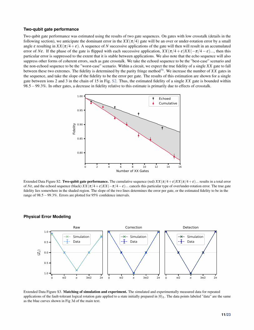
Two-qubit gate performance
Two qubit gate performance was estimated using the results of two gate sequences. On gates with low crosstalk (details in thefollowing section), we anticipate the dominant error in the XX(π/4) gate will be an over or under-rotation error by a smallangle ε resulting in XX(π/4+ ε). A sequence of N successive applications of the gate will then will result in an accumulatederror of Nε . If the phase of the gate is flipped with each successive application, XX(π/4+ ε)XX(−π/4− ε)..., then thisparticular error is suppressed to the extent that it is stable between applications. We also note that the echo sequence will alsosuppress other forms of coherent errors, such as gate crosstalk. We take the echoed sequence to be the ”best-case” scenario andthe non-echoed sequence to be the ”worst-case” scenario. Within a circuit, we expect the true fidelity of a single XX gate to fallbetween these two extremes. The fidelity is determined by the parity fringe method56. We increase the number of XX gates inthe sequence, and take the slope of the fidelity to be the error per gate. The results of this estimation are shown for a singlegate between ions 2 and 3 in the chain of 15 in Fig. S2. Thus, the estimated fidelity of a single XX gate is bounded within98.5−99.3%. In other gates, a decrease in fidelity relative to this estimate is primarily due to effects of crosstalk.
Extended Data Figure S2. Two-qubit gate performance. The cumulative sequence (red) XX(π/4+ε)XX(π/4+ε)... results in a total errorof Nε , and the echoed sequence (black) XX(π/4+ ε)XX(−π/4− ε)... cancels this particular type of over/under-rotation error. The true gatefidelity lies somewhere in the shaded region. The slope of the two lines determines the error per gate, or the estimated fidelity to be in therange of 98.5−99.3%. Errors are plotted for 95% confidence intervals.
Physical Error Modeling
0 π/2 π 3π/2 2πθ
−1.0
−0.5
0.0
0.5
1.0
⟨ZL⟩
Raw
SimulationData
0 π/2 π 3π/2 2πθ
⟨orrection
SimulationData
0 π/2 π 3π/2 2πθ
⟩etection
SimulationData
Extended Data Figure S3. Matching of simulation and experiment. The simulated and experimentally measured data for repeatedapplications of the fault-tolerant logical rotation gate applied to a state initially prepared in |0〉L. The data points labeled ”data” are the sameas the blue curves shown in Fig 3d of the main text.
11/23

To confirm our understanding of the experimental system, we find it useful to design physical error models that can replicateour experimental results in simulation. A simple coherent overrotation error model, combined with stochastic measurement andpreparation errors closely matches our results, as shown in Fig. S3. The coherent overrotation error channel for a rotation gateG is modeled as
εG(ρ) = exp(−iθG)ρ exp(iθG), (S2)
where θ is the angle of overrotation. This model is applied to both the Mølmer-Sørensen gate and the single qubit rotationgates, where the fidelities presented in the main text are directly translated into values for θ . These two errors are demonstratedin Fig. S4. The simulation then includes stochastic measurement errors and preparation errors following the SPAM error ratesdetermined from our benchmarking experiments presented in the SPAM error benchmarking section above. Using this fourparameter error model, we can capture much of the performance of our system.
Extended Data Figure S4. Gate error model for CNOT. One possible choice of native gate decomposition (black) and gate errors (red) for aCNOT gate.
Circuit optimization for crosstalk
There are several factors to consider when mapping the Bacon-Shor code onto a chain of 15 ions, as shown in Fig. 1 of themain text. In general, ion chains feature all-to-all two-qubit gate connectivity; however, some gates require more optical powerthan others to achieve maximal entanglement. Considering errors that scale with intensity, such as crosstalk, then gate fidelityis expected to decrease with increasing power requirements. These differences in power requirements can be understood byexamining the mode participation symmetries in the chain. For example, ion 8, the center ion, requires high power in nearly allof its gates because it only participates in the even spatial modes (i.e., b8,2n = 0, n = 1,2, ...,7 where bi,1 is mode-participationfactor of the highest-frequency in-phase radial mode for ion i). So on average, for a fixed gate frequency, the modes that driveentanglement are further detuned from the gate. We note that this is unique to our choice of amplitude modulated (AM) gateswith a fixed frequency; phase/frequency-modulated (PM/FM) gates or multi-tone gates may have different chain symmetryconsiderations.
In Fig. S5, we present the power requirements for the gates in our system. We first optimize the frequency of each gateacross the mode spectrum to find pulse solutions that are robust to mode errors of < 1 kHz. Once the frequency is fixed foreach gate, we calculate the root-mean-square (RMS) Rabi frequency (Ωrms) of the AM waveform for each red/blue sidebandwhen brought into resonance with the carrier transition. In our system, we use equal Rabi frequencies to drive both ions i, j inthe gate (Ωi,rms = Ω j,rms), although this need not be case. The Lamb-Dicke factor (η ≈ 0.08) converts carrier Rabi frequencyto sideband frequency and this factor is normalized by the gate duration (τgate = 225µ s). Using Fig. S5 as a cost matrix, wemanually optimize the mapping so that the required gates in the circuit minimize the total cost. In general, we observe that eachhalf of the chain has strong coupling to itself, and the two halves of the chain couple well to each other as long as symmetryof the chain is obeyed (e.g., gates where the ions are with both odd or both even integer offsets from the center of the chaincouple well, but mixed even and odd integer offsets do not). We further note that when considering the full stabilizer circuit, itis preferable to use ion 8 as a data qubit (maximum 4 gates) than as an ancilla qubit (6 gates). With these considerations, wearrived at the ion→qubit mapping displayed in Fig. 1 of the main text.
12/23

2 3 4 5 6 7 8 9 10 11 12 13 14
Gate on Ion j
2
3
4
5
6
7
8
9
10
11
12
13
14
Gat
e on
Ion
i
i, rms j, rms( / gate)2
2.0
2.5
3.0
3.5
4.0
4.5
5.0
Extended Data Figure S5. Power requirements for XX gates in our system. For an XX gate on ions i, j, the (RMS) Rabi frequency (Ωrms)of the AM waveform for each red/blue sideband when brought into resonance with the carrier transition is normalized by the Lamb-Dickefactor (η ≈ 0.08) and the gate duration (τgate = 225µs). Gate power is used as a proxy for crosstalk, and the ion→qubit mapping is chosen tominimize the cost matrix.
Magic State FidelityTo calculate the fidelity of our magic state preparation circuit for the state |Hx〉L, we can compute the fidelity between a mixedstate ρ , which represents the experimentally prepared state, and the ideal pure state |ψ〉 as
F = 〈ψ|ρ|ψ〉= Tr[ρ|ψ〉〈ψ|]
=12(1+ 〈X〉ρ〈X〉ψ + 〈Y 〉ρ〈Y 〉ψ + 〈Z〉ρ〈Z〉ψ
)=
12
(1+ 〈X〉ρ
1√2+ 〈Z〉ρ
1√2
).
(S3)
The expectation values 〈Z〉ρ and 〈X〉ρ can be extracted by measuring logical Z operator before and after a logical YL(π/2)operation. This analysis leads to the following fidelities as shown in Table S2.
Processing Technique FidelityRaw 0.85±0.01
Correction 0.972±0.012Detection 0.98±0.013
Table S2. Fidelities for the |Hx〉L magic state preparation circuit under different processing techniques.
However the same procedure cannot be applied to the |Hy〉L state, as the [[9,1,3]] Bacon-Shor code does not allow forfault-tolerant measurement in the logical Y basis. Using the constraint
〈X〉2 + 〈Y 〉2 + 〈Z〉2 ≤ 1
we can only numerically bound the fidelity of the |Hy〉L state to the range 0.75≤ F ≤ 0.99. However, we argue that the fidelitiesfor preparing |Hx〉L and |Hy〉L should be very similar, as the preparation circuit only differs in the phase of a single qubit gate, aquantity which we control to ≈ 400µrad limited by the AWG bit depth. This argument is further strengthened by the results ofour single qubit benchmarking. Thus the |Hy〉L state fidelity should be very similar to values shown in Table S2.
13/23

Logical T ∗2 fitsThe Ramsey fringe amplitudes shown in Fig. 2c are calculated by fitting a curve to a logical Ramsey experiment at each waittime. The data is taken by preparing a |+〉L state as shown in Eq. 1, waiting some amount of time t, applying varying RZ(θ)gates to every qubit and then measuring in the logical X basis via a transversal RYL(−π/2) . Here we will explain the theoreticalfits used for raw, corrected, and detected data processing techniques.
Firstly, as shown in Eq. 1, the logical |+〉 state we use is composed of three GHZ states 1√2(|000〉+ |111〉). Due to the
structure of these states, if a RZ(θ) gate is applied to each qubit, the three gates will coherently combine, and the end result willbe the same as if a RZ(3θ) gate had been applied on any single qubit. By considering this simplification we can reduce thenumber of error cases we must consider.
For the ’raw’ processing case, any Z error flips the logical output. As a result the cases where 1 or 3 errors occur lead to |−〉Lstates, while while cases with 0 or 2 errors lead to |+〉L. Consequently the expectation value of XL can be thought of as thesquared amplitude of cases which lead to |+〉L, subtracted by the squared amplitude of cases which result in |−〉L. This resultsin a curve
〈XL〉= cos(3θ/2)6−3cos(3θ/2)4 sin(3θ/2)2 +3cos(3θ/2)2 sin(3θ/2)4− sin(3θ/2)6 = cos(3θ)3.
In the ’corrected’ processing case, the state can tolerate a single error without having its logical information corrupted. As aresult error cases with 0 or 1 errors lead to |+〉L, while 2 or 3 lead to |−〉L. This results in the curve
〈XL〉= cos(3θ/2)6 +3cos(3θ/2)4 sin(3θ/2)2−3cos(3θ/2)2 sin(3θ/2)4− sin(3θ/2)6.
Lastly the ’detected’ processing method is slightly more complex, as postselection means we must renormalize the expectationvalue. The case with 0 errors leads to |+〉L, while the case with 3 errors leads to |−〉L. Cases with 1 or 2 errors must setoff at least one stabilizer, and as a result those runs will be removed from the dataset. As a result the probabilities must berenormalized, leading to the curve
〈XL〉=cos(3θ/2)6− sin(3θ/2)6
cos(3θ/2)6 + sin(3θ/2)6 .
In an experiment there will also be imperfections in the states due to errors beyond T ∗2 dephasing, which we model to be asimple depolarization of each GHZ state with strength p. This corresponds to taking a state |+〉GHZ → (1− p)|+〉〈+|GHZ +p2 (|+〉〈+|GHZ + |−〉〈−|GHZ), where the second term, equal to the maximally mixed state on the space spanned by |000〉 and|111〉, has an expectation value of 0.
In the raw case, any depolarization of the GHZ states will lead to the expectation value going to zero, and as a result the onlynon-zero expectation values come about when no depolarization occurs. As a result the overall fringe pattern is simply scaledby a factor of (1− p)3:
〈XL〉= A(1− p)3 cos(3θ)3.
In the correction case the stabilizers are able to identify and correct a single depolarization error. This leads to different casesfor when depolarization occurs and when they do not, which when collated lead to:
〈XL〉=[(1− p)3 +3(1− p)2 p+
3p2(1− p)2
](cos(3θ/2)6− sin(3θ/2)6)
+
[3(1− p)3 +3(1− p)2 p+
3p2(1− p)2
](sin(3θ/2)2 cos(3θ/2)4− sin(3θ/2)4 cos(3θ/2)2).
The most complex case is the detection case. Individual depolarizations each contribute a 12 chance of setting off a stabilizer,
and when they do not the coherent rotations on the other qubits produce similar behaviors to the ideal detection case, but onlyon the non-depolarized qubits. This leads to the equation:
〈XL〉= A[(1− p)3
(cos(3θ/2)6− sin(3θ/2)6
cos(3θ/2)6 + sin(3θ/2)6
)+
3p(1− p)2
2
(cos(3θ/2)4− sin(3θ/2)4
cos(3θ/2)4 + sin(3θ/2)4
)+
3p2(1− p)4
(cos(3θ/2)2− sin(3θ/2)2
cos(3θ/2)2 + sin(3θ/2)2
)].
14/23

These models well describe the experimental data, as shown in Fig. S6.
Raw DetectionCorrection
Extended Data Figure S6. Examples of T ∗2 fits. These plots exemplify logical Ramsey fringe fitting at two different wait times, 0ms (left)and 14ms (right). At short wait times (left), the data shows characteristics of error correction, such as the flattened top for error-detection. Atlonger wait times (right), the amplitude of each curve decreases due to T ∗2 , but also the flat features of the curves blur due to GHZdepolarization. In both cases, the error model well matches the experimental data. Error bars are the 95% binomial proportion confidenceinterval
Physical T ∗2To understand the phase flip errors in the logical qubit, we measure the T ∗2 of the physical qubits in a chain of 15 ions. This isaccomplished via a laser Raman Ramsey sequence on the center ion, RY (π/2)− τwait−RZ(θ)−RY (−π/2), with no echoes.At each wait time τwait, the phase θ is swept, and the resulting data is fit to a sinusoid to extract the contrast. The Ramseycontrast is fit to a decaying exponential Ae−τwait/T ∗2 to extract T ∗2 . The results of this experiment are shown in Fig. S7. We findT ∗2 = 610(120) ms for a physical qubit in a chain of 15 ions. We attribute the physical qubit decoherence primarily to controlnoise, rather than to fundamental qubit decoherence. In particular, we note that there are features of revivals at ≈ 8 ms and 16ms, corresponding to noise at ≈ 125 Hz. We assign this to mechanical fluctuations (e.g., fans) that shift the standing wave ofthe optical Raman beams relative to the ions. This effect can be mitigated by switching to a ”phase-insensitive” configuration57.
0 5 10 15 20Wait Time (ms)
0.92
0.93
0.94
0.95
0.96
0.97
0.98
Ram
sey
Frin
ge A
mpl
itude
T *2 = 610(120) ms
Extended Data Figure S7. Raman T ∗2 for a physical qubit in a 15-ion chain. Ramsey fringes with variable wait times are fit to a sinusoudto extract the contrast. For each data point, the error bars represent the 95% confidence interval from a maximal likelihood estimation fit of asinuosoid. The contrast is fit to a decaying exponential Ae−τwait/T ∗2 , with fit value T ∗2 = 610(120) ms. The shaded region indicates the 1σ
uncertainty in the exponential least-squares fit.
To investigate the degree to which control errors impact our physical T ∗2 qubit decoherence, we perform microwave Ramsey
15/23

experiments, which are not sensitive to optical beam path fluctuations. Additionally, we suppress magnetic field inhomogeneityusing a dynamical decoupling technique that applies π-pulses with alternating 90° phase offsets, commonly known as an (XY )N
pulse sequence58, to periodically refocus the qubit spin. Due to a strong microwave drive field gradient along the ion chain, theπ-pulse times are only well calibrated for three neighboring ions in the chain, which we center on the middle ion (8) in thechain. At each wait time, the phase of the fringe is swept, and the resulting data is fit to a sinusoid to extract the contrast. Theresulting data is shown in Fig. S8. We observe that the resulting decay is better fit to a Gaussian (Ae−(τwait/T2)
2), compared to an
exponential decay, with average T2 = 2.84(16) s. The coherence time of this echo experiment is limited by residual magneticfield noise, which can be improved by operating our qubit in a lower bias-field or by using magnetic shielding. We note thatT2 > 1 hour has been achieved in 171Yb+59.
0.0 0.5 1.0 1.5 2.0 2.5 3.0Wait Time (s)
0.0
0.2
0.4
0.6
0.8
1.0Ra
mse
y Fr
inge
Am
plitu
de
1/eIon 7Ion 8Ion 9
Extended Data Figure S8. Microwave T2 for a physical qubit in a 15-ion chain. An (XY )N dynamical decoupling sequence is used tosuppress magnetic field noise. Ramsey fringes with variable wait times are fit to a sinusoud to extract the contrast. For each data point, theerror bars represent the 1σ confidence interval from a least-squares fit of a sinuosoid. The contrast is fit to a Gaussian decay Ae−(τwait/T2)
2,
with average fit value T2 = 2.84(16) s.
0.0 2.5 5.0 7.5 10.0 12.5 15.0 17.5 20.0Wait Time (ms)
0.4
0.5
0.6
0.7
0.8
0.9
1.0
Ram
sey
Frin
ge A
mpl
itude
Predicted GHZGHZ 1GHZ 2GHZ 3
Extended Data Figure S9. T ∗2 for GHZ states. Ramsey fringes for each independent GHZ state are analyzed from the logical T ∗2 experimentin Fig. 2c of the main text. For each data point, the error bars represent the 95% confidence interval from a maximal likelihood estimation fitof a sinuosoid. For the theoretical prediction, we apply the fitted dephasing noise in Fig. S7 to a numerical simulation of a three-qubit GHZstate. The shaded region indicates the 1σ uncertainty in the exponential least-squares fit in Fig. S7, propagated through the numericalsimulation.
The GHZ states that make up the Bacon-Shor code (|000〉+ |111〉) are three times as sensitive to phase noise as our physicalqubit. To understand the implication of the Raman T ∗2 on the logical T ∗2 , we run numerical simulations to extrapolate the
16/23

measured phase noise to a GHZ state. We assume that the Pauli-Z noise in the middle of the Ramsey sequence is Gaussiandistributed with some width ∆Z . Using the fit from Fig. S7, we can numerically solve for the width of the noise spectrum∆Z . Once this value is found, we re-run the simulation with that noise spectrum on a three-qubit GHZ state to extract thepredicted contrast. In Fig. S9, we compare this predicted value to the three individual GHZ states measured in the logicalqubit experiment. We conclude that almost all the dephasing in the logical qubit that we observe is explained by the observedT ∗2 - decay in the physical qubit. We note that this is the same experimental data presented in Fig. 2c of the main text, justpost-processed to analyze individual GHZ states rather than to perform error-correction.
Bacon-Shor gauge operatorsThe Bacon-Shor code is an example of a subsystem quantum error correcting code. These codes have additional quantumdegrees of freedom which are not protected to the same distance as the logical degree of freedom. In the [[9,1,3]] Bacon-Shorcode, there are 4 additional degrees of freedom referred to as gauge qubits. One basis for the gauge qubits corresponds to fixing4 constraints on the eigenvalues of the operators shown in the table below.
X-gauges Z-gaugesX1X2 Z1Z4X4X5 Z2Z5X7X8 Z3Z6X2X3 Z4Z7X5X6 Z5Z8X8X9 Z6Z9
It should be noted that this is not an independent set of operators because the stabilizers of the code, which are products ofgauges, already have their eigenvalues fixed to +1. As such, if the X-gauges X1X2 and X4X5 both have eigenvalue +1 on agiven logical state, then the eigenvalue of X7X8 will also be +1. We refer to a state in which all X(Z)-type gauge operators haveeigenvalue +1 as the |X〉G(|Z〉G) gauge. It should be noted that these gauge operators do not commute, so these two gauges aremutually exclusive. When decoding the Bacon-Shor code, we can only identify operators up to a product of gauges. When thecorrection is applied, we may have inadvertently applied a gauge operator to the logical state. This leaves our logical qubitunaffected, but will alter the state of the gauge qubits.
Logical Pauli operators on a subsystem code decompose as a tensor product of operations on the logical and gauge degreesof freedom. When a logical Pauli operator that acts non-trivially on the gauge subsystem is used to generate a continuousunitary operator, it will entangle the logical and gauge subsystems. As these gauge subsystems are less protected than thelogical subsystem, the information will be less protected. Consequently, one must design continuous logical operators aroundlogical Pauli operations that commute with the entire gauge group, ensuring that it acts trivially on the gauge subsystem.
Fit values for logical gate operationsIn Table. S3 and S4, we report the numerical values obtained from fitting the logical gate operations as displayed in Fig. 4d ofthe main text. In addition to the FT transversal gate and the nFT continuous gate, we also provide the fit values for a similarsampling of states in the logical XZ-plane generated from the nFT encoding circuit (Fig. 2a of main text). Error values arereported as the 1σ from a Gaussian approximation to a maximal likelihood estimation fit. The Gaussian approximation failswhen the fit parameters are at or equal to their extrema (e.g., when A' 1), in which case asymmetric error bars are given by thenotation (
1σupper1σ lower).
Amplitude (A) Raw Error Correction Error DetectionFT Gate 0.923(6) 0.996(1) 1.000(0
3)nFT Gate 0.89(1) 0.87(1) 1.00(0
1)nFT Encoding 0.78(1) 0.982(5) 0.997(2)
Table S3. Numerical values for the fit parameter A.
Gate Error (Γ) Raw Error Correction Error DetectionFT Gate 0.044(3) 0.0027(7) 0.0002(1)
nFT Gate 0.015(5) 0.000(4) 0.011(2)nFT Encoding 0.001(6) 0.000(2) 0.001(1)
Table S4. Numerical values for the fit parameter Γ.
17/23

Stabilizers on different input statesIn the main text (Fig 3a), we describe an experiment to measure X-type errors on the logical qubit state propagated from aZ-type errors on an ancilla during a FT X stabilizer measurement circuit. In that experiment, there was no detectable change inthe error rate. However, because the input and measured state was |0〉L, the measurement is only sensitive to X-type errors. Tocheck if the stabilizer is introducing Z-type errors into the logical qubit, we perform the same experiment (with no artificial erroradded) on the |+〉L input state. |+〉L is measured in the 〈X〉L basis by a transversal YL(−π/2) gate that maps 〈X〉L→ 〈Z〉L. Wealso check a Z stabilizers on both input states. The results are shown in Table S5. We note that from the logical T ∗2 experiment,we expect the error on the |+〉L state to increase by 1.8% over the ≈ 1.5ms required to measure the stabilizer, which is notincluded in the baseline encoding error below.
Input State Baseline Encoding FT Z Stabilizer FT X Stabilizer(% Error) (% Error) (% Error)
|0〉L 0.23(13) 0.41(10) 0.20(13)|+〉L 0.45(11) 3.3(3) 2.1(2)
Table S5. Logical error rates for both Z and X FT stabilizers on different logical input states, after error-correction.Uncertainties are 1σ from the binomial distribution.
Extended stabilizer resultsIn Fig. 3 of the main text, we presented a representative sample of artificially introduced errors and the corresponding ancillaqubit populations. Here in Fig. S10, we present a full set of errors that produce all of the possible ancilla qubit output bit strings.
Extended Data Figure S10. Full stabilizer measurement results. A complete set of errors are introduced to create all possible output bitstrings of the ancilla qubits. Error bars are the 95% binomial proportion confidence interval.
For a given error, each stabilizer measurement yields a deterministic eigenvalue measurement (e.g., +1,−1,−1,+1) thatis mapped to the ancilla qubit state (e.g., 0,1,1,0). Defining the error as the difference between the expected ancilla bitstring and the measured populations, and averaging across all the artificial errors, we obtain the following total error for eachstabilizer measurement:
Stabilizer Total Error (εSi )S1 = Z1Z4Z2Z5Z3Z6 0.244(3)S2 = Z4Z7Z5Z8Z6Z9 0.298(6)S3 = X1X2X4X5X7X8 0.179(3)S4 = X2X3X5X6X8X9 0.248(3)
In this experiment, the stabilizers are measured in the order S3,S4,S1,S2. We note from the data presented in Fig. 2 of themain text, the raw encoding of the |0〉L state has a base εenc = 0.038(2) error, which we assume is isotropic in the sense that allstabilizer measurements should see the error equally. Additionally, stabilizer measurements will detect errors introduced byitself or previous stabilizer measurements, which we assume to be isotropic as well. The per stabilizer error can be calculated bythe differential error between successive stabilizer measurements. We calculate εZ = 0.064(7) per Z-stabilizer (avg. 98.9% gatefidelity) and εX = 0.069(5) per X-stabilizer (avg. 98.8% gate fidelity). Finally, we observe an error offset on the X-stabilizers
18/23
relative to the Z-stabilizers of εT ∗2= 0.072(5), consistent with a Z-type error caused by the logical qubit dephasing (T ∗2 ) over
the wall-clock time it takes to measure the X-stabilizers (≈ 3 ms), as presented in Fig. 2c of the main text. In conclusion, wefind that the total stabilizer measurement error for each ancilla qubit is well explained by the following error model:
εS1 = εenc +2εX + εZ
εS2 = εenc +2εX +2εZ
εS3 = εenc + εT ∗2+ εX
εS4 = εenc + εT ∗2+2εX
(S4)
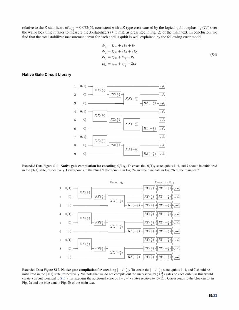
Native Gate Circuit Library
1 |0/1〉XX( π
4 )
2 |0〉 RZ( π2 )
XX(− π4 )
3 |0〉 RZ(− π2 )
4 |0/1〉XX( π
4 )
5 |0〉 RZ( π2 )
XX(− π4 )
6 |0〉 RZ(− π2 )
7 |0/1〉XX( π
4 )
8 |0〉 RZ( π2 )
XX(− π4 )
9 |0〉 RZ(− π2 )
Extended Data Figure S11. Native gate compilation for encoding |0/1〉L. To create the |0/1〉L state, qubits 1, 4, and 7 should be initializedin the |0/1〉 state, respectively. Corresponds to the blue Clifford circuit in Fig. 2a and the blue data in Fig. 2b of the main text/
Encoding Measure 〈X〉L
1 |0/1〉XX( π
4 )RY ( π
2 ) RY (− π2 )
2 |0〉 RZ( π2 )
XX(− π4 )
RY ( π2 ) RY (− π
2 )
3 |0〉 RZ(− π2 ) RY ( π
2 ) RY (− π2 )
4 |0/1〉XX( π
4 )RY ( π
2 ) RY (− π2 )
5 |0〉 RZ( π2 )
XX(− π4 )
RY ( π2 ) RY (− π
2 )
6 |0〉 RZ(− π2 ) RY ( π
2 ) RY (− π2 )
7 |0/1〉XX( π
4 )RY ( π
2 ) RY (− π2 )
8 |0〉 RZ( π2 )
XX(− π4 )
RY ( π2 ) RY (− π
2 )
9 |0〉 RZ(− π2 ) RY ( π
2 ) RY (− π2 )
❴ ❴ ❴ ❴ ❴
❴ ❴ ❴ ❴ ❴
Extended Data Figure S12. Native gate compilation for encoding |+/−〉L. To create the |+/−〉L state, qubits 1, 4, and 7 should beinitialized in the |0/1〉 state, respectively. We note that we do not compile out the successive RY (± π
2 ) gates on each qubit, as this wouldcreate a circuit identical to S11 - this explains the additional error on |+/−〉L states relative to |0/1〉L. Corresponds to the blue circuit inFig. 2a and the blue data in Fig. 2b of the main text.
19/23

1 |0〉 R(θ, φ) RY ( π2 ) XX( π
4 ) XX(− π4 ) RY (− π
2 )XX( π
4 )
2 |0〉 RZ( π2 )
XX(− π4 )
3 |0〉 RZ(− π2 )
4 |0〉 XX( π4 ) RX(− π
2 )XX( π
4 )
5 |0〉 RZ( π2 )
XX(− π4 )
6 |0〉 RZ(− π2 )
7 |0〉 XX(− π4 ) RX( π
2 )XX( π
4 )
8 |0〉 RZ( π2 )
XX(− π4 )
9 |0〉 RZ(− π2 )
Extended Data Figure S13. Native gate compilation for nFT encoding of arbitrary logical states. This circuit can create an arbitrary|ψ〉L state controlled by the initial R(θ ,φ) gate on qubit 1, with |ψ〉1 = R(θ ,φ)|0〉1. Corresponds to the red circuit in Fig. 2a and the red datain Fig. 2b of the main text. This circuit is also used for initial encoding of the magic states in Fig. c-d of the main text.
1 RX( π2 ) XX(− π
4 ) RZ(− π2 )
XX(θ)RZ( π
2 ) XX( π4 ) RX(− π
2 )
2 XX(− π4 ) RZ(− π
2 ) RZ( π2 ) XX( π
4 )
3 XX(− π4 ) RZ(− π
2 ) XX(− π4 ) XX( π
4 ) RZ( π2 ) XX( π
4 )
4 XX(− π4 ) XX( π
4 )
5
6
7 XX(− π4 ) XX( π
4 )
8
9
Extended Data Figure S14. Native gate compilation for nFT continuous rotation. This circuit implements a YL(θ) = Y1Z2Z3X4X7(θ)rotation controlled by an XX(θ) gate on qubits 1 and 2. Corresponds to the red circuit in Fig. 3b and the red data in Fig. 3d-e of the main text.
20/23

1 RY (+) XX(+) RX(−) RY (−)
2 RY (+) XX(+) RX(−) RY (−)
3 RY (+) XX(+) RX(−) RY (−)
4 RY (+) XX(−) XX(+) RY (−)
5 RY (+) XX(−) XX(+) RY (−)
6 RY (+) XX(−) XX(+) RY (−)
7 RY (+) XX(−) RX(+) RY (−)
8 RY (+) XX(−) RX(+) RY (−)
9 RY (+) XX(−) RX(+) RY (−)
10 |0〉 XX(+) XX(−) XX(+) XX(−) XX(+) XX(−)
11 |0〉 XX(+) XX(−) XX(+) XX(−) XX(+) XX(−)
Extended Data Figure S15. Native gate compilation for Z stabilizer measurement. Here, the angle (+/−) is shorthand for (± π
2 ) or (± π
4 )for single- or two-qubit gates, respectively. When combined with encoding (Fig. S11) and the X stabilizer (Fig. S16), the combined circuitsmeasure the full syndrome (Extended Data Fig. 1a).
1 XX(−) RX(−)
2 XX(+) XX(−)
3 XX(+) RX(+)
4 XX(−) RX(−)
5 XX(+) XX(−)
6 XX(+) RX(+)
7 XX(−) RX(−)
8 XX(+) XX(−)
9 XX(+) RX(+)
12 |0〉 XX(−) XX(+) XX(−) XX(+) XX(−) XX(+)
13 |0〉 XX(−) XX(+) XX(−) XX(+) XX(−) XX(+)
Extended Data Figure S16. Native gate compilation for FT X stabilizer measurement. Here, the angle (+/−) is shorthand for (± π
2 ) or(± π
4 ) for single- or two-qubit gates, respectively. Corresponds to the circuit in Extended Data Fig. 1c and for data presented in Fig. 4a of themain text.
References1. Feynman, R. P. Quantum mechanical computers. Foundations Phys. 16, 507–531 (1986).
2. Abrams, D. S. & Lloyd, S. Simulation of many-body fermi systems on a universal quantum computer. Phys. Rev. Lett. 79,2586 (1997).
3. Aspuru-Guzik, A., Dutoi, A. D., Love, P. J. & Head-Gordon, M. Simulated quantum computation of molecular energies.Science 309, 1704–1707 (2005).
21/23

4. Reiher, M., Wiebe, N., Svore, K. M., Wecker, D. & Troyer, M. Elucidating reaction mechanisms on quantum computers.Proc. Natl. Acad. Sci. 114, 7555–7560 (2017).
5. Shor, P. W. Polynomial-time algorithms for prime factorization and discrete logarithms on a quantum computer. SIAM Rev.41, 303–332 (1999).
6. Von Burg, V. et al. Quantum computing enhanced computational catalysis. Preprint at https://arxiv.org/abs/2007.14460(2020).
7. Gidney, C. & Ekera, M. How to factor 2048 bit rsa integers in 8 hours using 20 million noisy qubits. Preprint athttps://arxiv.org/abs/1905.09749 (2019).
8. Aharonov, D. & Ben-Or, M. Fault-tolerant quantum computation with constant error rate. SIAM J. on Comput. (2008).
9. Knill, E., Laflamme, R. & Zurek, W. Threshold accuracy for quantum computation. Preprint at https://arxiv.org/abs/quant-ph/9610011 (1996).
10. Gottesman, D. E. Stabilizer Codes and Quantum Error Correction. Ph.D. thesis, California Institute of Technology (1997).
11. Shor, P. W. Scheme for reducing decoherence in quantum computer memory. Phys. Rev. A 52, R2493 (1995).
12. Knill, E. & Laflamme, R. Theory of quantum error-correcting codes. Phys. Rev. A 55, 900 (1997).
13. Corcoles, A. D. et al. Demonstration of a quantum error detection code using a square lattice of four superconductingqubits. Nat. Commun. 6, 1–10 (2015).
14. Takita, M., Cross, A. W., Corcoles, A., Chow, J. M. & Gambetta, J. M. Experimental demonstration of fault-tolerant statepreparation with superconducting qubits. Phys. Rev. Lett. 119, 180501 (2017).
15. Linke, N. M. et al. Fault-tolerant quantum error detection. Sci. Adv. 3, e1701074 (2017).
16. Harper, R. & Flammia, S. T. Fault-tolerant logical gates in the ibm quantum experience. Phys. Rev. Lett. 122, 080504(2019).
17. Andersen, C. K. et al. Repeated quantum error detection in a surface code. Nat. Phys. 1–6 (2020).
18. Cory, D. G. et al. Experimental quantum error correction. Phys. Rev. Lett. 81, 2152 (1998).
19. Chiaverini, J. et al. Realization of quantum error correction. Nature 432, 602–605 (2004).
20. Schindler, P. et al. Experimental repetitive quantum error correction. Science 332, 1059–1061 (2011).
21. Reed, M. D. et al. Realization of three-qubit quantum error correction with superconducting circuits. Nature 482, 382–385(2012).
22. Riste, D. et al. Detecting bit-flip errors in a logical qubit using stabilizer measurements. Nat. Commun. 6, 1–6 (2015).
23. Kelly, J. et al. State preservation by repetitive error detection in a superconducting quantum circuit. Nature 519, 66–69(2015).
24. Gong, M. et al. Experimental verification of five-qubit quantum error correction with superconducting qubits. Preprint athttps://arxiv.org/abs/1907.04507 (2019).
25. Nigg, D. et al. Quantum computations on a topologically encoded qubit. Science 345, 302–305 (2014).
26. Luo, Y.-H. et al. Quantum teleportation of physical qubits into logical code-spaces. Preprint athttps://arxiv.org/abs/2009.06242 (2020).
27. Heeres, R. W. et al. Implementing a universal gate set on a logical qubit encoded in an oscillator. Nat. communications 8,1–7 (2017).
28. Fluhmann, C. et al. Encoding a qubit in a trapped-ion mechanical oscillator. Nature 566, 513–517 (2019).
29. Ofek, N. et al. Extending the lifetime of a quantum bit with error correction in superconducting circuits. Nature 536,441–445 (2016).
30. Campagne-Ibarcq, P. et al. Quantum error correction of a qubit encoded in grid states of an oscillator. Nature 584, 368–372(2020).
31. Bravyi, S. & Kitaev, A. Universal quantum computation with ideal clifford gates and noisy ancillas. Phys. Rev. A 71,022316 (2005).
32. Maunz, P. L. W. High optical access trap 2.0. Sandia Natl. Lab. Rep. No. SAND2016-0796R (2016).
33. Debnath, S. et al. Demonstration of a small programmable quantum computer with atomic qubits. Nature 563, 63 (2016).
22/23

34. Wright, K. et al. Benchmarking an 11-qubit quantum computer. Nat. communications 10, 1–6 (2019).
35. Bacon, D. Operator quantum error-correcting subsystems for self-correcting quantum memories. Phys. Rev. A 73, 012340(2006).
36. Aliferis, P. & Cross, A. W. Subsystem fault tolerance with the Bacon-Shor code. Phys. Rev. Lett. 98, 220502 (2007).
37. Debroy, D. M., Li, M., Huang, S. & Brown, K. R. Logical performance of 9 qubit compass codes in ion traps with crosstalkerrors. Quantum Sci. Technol. 5, 034002 (2020).
38. Li, M., Miller, D. & Brown, K. R. Direct measurement of Bacon-Shor code stabilizers. Phys. Rev. A 98, 050301 (2018).
39. Shor, P. Fault-tolerant quantum computation. Proc. 37th Conf. on Foundations Comput. Sci. (1996).
40. Terhal, B. M. Quantum error correction for quantum memories. Rev. Mod. Phys. 87, 307 (2015).
41. Dennis, E., Kitaev, A., Landahl, A. & Preskill, J. Topological quantum memory. J. Math. Phys. 43, 4452–4505 (2002).
42. Li, M., Miller, D., Newman, M., Wu, Y. & Brown, K. R. 2D compass codes. Phys. Rev. X 9, 021041 (2019).
43. Reichardt, B. W. Quantum universality from magic states distillation applied to CSS codes. Quantum Inf. Process. 4,251–264 (2005).
44. Lidar, D. A., Chuang, I. L. & Whaley, K. B. Decoherence-free subspaces for quantum computation. Phys. Rev. Lett. 81,2594 (1998).
45. Kielpinski, D. et al. A decoherence-free quantum memory using trapped ions. Science 291, 1013–1015 (2001).
46. Eastin, B. & Knill, E. Restrictions on transversal encoded quantum gate sets. Phys. Rev. Lett. 102, 110502 (2009).
47. Cetina, M. et al. Quantum gates on individually-addressed atomic qubits subject to noisy transverse motion. Preprint athttps://arxiv.org/abs/2007.06768 (2020).
48. Kielpinski, D., Monroe, C. & Wineland, D. J. Architecture for a large-scale ion-trap quantum computer. Nature 417,709–711 (2002).
49. Home, J. P. et al. Complete methods set for scalable ion trap quantum information processing. Science 325, 1227–1230(2009).
50. Pino, J. et al. Demonstration of the QCCD trapped-ion quantum computer architecture. Preprint athttps://arxiv.org/abs/2003.01293 (2020).
51. Brown, K. R., Harrow, A. W. & Chuang, I. L. Arbitrarily accurate composite pulse sequences. Phys. Rev. A 70, 052318(2004).
52. Mølmer, K. & Sørensen, A. Multiparticle entanglement of hot trapped ions. Phys. Rev. Lett. 82, 1835 (1999).
53. Maslov, D. Basic circuit compilation techniques for an ion-trap quantum machine. New J. Phys. 19, 023035 (2017).
54. Knill, E. et al. Randomized benchmarking of quantum gates. Phys. Rev. A 77, 012307 (2008).
55. Barends, R. et al. Superconducting quantum circuits at the surface code threshold for fault tolerance. Nature 508, 500–503(2014).
56. Sackett, C. A. et al. Experimental entanglement of four particles. Nature 404, 256–259 (2000). Number: 6775 Publisher:Nature Publishing Group.
57. Inlek, I., Vittorini, G., Hucul, D., Crocker, C. & Monroe, C. Quantum gates with phase stability over space and time. Phys.Rev. A 90, 042316 (2014).
58. Gullion, T., Baker, D. B. & Conradi, M. S. New, compensated carr-purcell sequences. J. Magn. Reson. (1969) 89, 479–484(1990).
59. Wang, P. et al. Single ion-qubit exceeding one hour coherence time. Preprint at https://arxiv.org/abs/2008.00251 (2020).
23/23