Embed Size (px)
Citation preview
23rd International Conference on Electricity Distribution Lyon, 15-18 June 2015
Paper 0598
CIRED 2015 1/5
FAULT ANALYSIS OF AN ISLANDED MICRO-GRID WITH DOUBLY FED INDUCTION
GENERATOR BASED WIND TURBINE
Yunqi WANG, B.T. PHUNG, Jayashri RAVISHANKAR School of Electrical Engineering and Telecommunications
The University of New South Wales, Sydney, Australia
ABSTRACT
The increasing penetration of distributed generations
(DGs) in the electrical system is causing severe transient
stability problems since most of DGs are characterized
by low inertias and poor inherent damping. In this paper,
an islanded micro-grid with both synchronous machine
and DGs is built to compare the transient stability of the
system when a three-phase to ground fault occurs. The
simulation result shows that the installation of DG
improves the dynamic performance of the micro-grid, and
when the DG source is the unit with the energy storage,
this improvement is much more significant as this device
can absorb power rush caused by the fault and it will
supply a reactive compensation to recover the voltage
after the fault. But this enhancement is reduced if the DG
penetration level is too low or too high. The micro-grid
with both storage unit and DFIG based wind turbine
shows the best transient performance since both these
DGs can reduce the negative effects from the fault.
Key words—Micro-grid, Fault, Wind Turbine, Battery
Storage, DFIG
INTRODUCTION
The micro-grid technology is efficient in the
sustainable development of the power industry, flexible
and efficient in the integrated use of distributed and
renewable power generation technology. And its power
supply system combines distributed generations (DGs)
with integrated system, which can reduce initial outlay,
investment risks and energy consumption. Energy
efficiency, power system reliability, power system
flexibility and energy quality can also be improved with
this system. And it will be an important development
direction of the electrical industry in the future [1-4].
The drawbacks with DGs is that they are
characterized by low inertias, high reactance, short time
constant and poor inherent damping [5], which means,
the dynamic performance of the whole system may be
affected since DGs are unable to regulate system
stability. This issue gets aggravated when networks begin
to incorporate large numbers of DGs, as the overall
dynamics of power system gets significantly impacted
[6].
Various researches in the past studied the transient
stability of the micro-grid with distributed generations.
Reference [7] proves that the usage of inverter-based DG
using droop control strategy improves the transient
stability of the distribution system for a three-phase-fault.
Reference [8] also shows that the micro-grid with a mix
of synchronous and inverter based DG has a better
transient stability performance.
These previous works have made the following
comparisons.
Comparing fault performance of micro-grid in grid-
connected / islanding mode.
Comparing fault performance of micro-grid with
different wind turbine conditions, including different
control, crowbar protection or wind turbine type. A
performance comparison of the wind turbines with
other DG types is not investigated.
Comparing fault performance of system with /
without DGs. The nature of these sources being DC,
they are equivalent to an energy source with storage
units or even a pure storage system.
The storage units are known to support the transient
performance of micro-grids during faults, by exchanging
the excess energy available in the system. However, with
AC sources like wind turbines employing doubly-fed
induction generators (DFIGs), for example, the transient
performance of the micro-grid significantly deteriorate,
as it does not have any energy storage parts and the
constantly change in the rotor speed of the wind turbine
also makes an impact on the micro-grid stability.
The main aim of this paper is to compare the fault
transients for micro-grids with synchronous machine,
DFIG wind turbine and storage device. The simulation is
carried out under four different scenarios: (i) the micro-
grid with only one synchronous generator, (ii) the micro-
grid with a synchronous generator (SG) and a DFIG wind
turbine, (iii) the micro-grid including a synchronous
generator and a storage unit, and (iv) the micro-grid
including a synchronous generator, a DFIG wind turbine
and a storage unit. A three-phase-fault is applied to the
system at the same bus and the fault clearing time is the
same for all simulation scenarios. The characteristics of
the SG and the point of common coupling are analyzed to
show the difference in transient performance.
FAULT PROTECTION OF DFIG WIND
TURBINE
For DFIG based wind turbine, crowbar is the most
commonly used protection method against the large short
circuit current caused by the suddenly drop of grid
voltage [9].
23rd International Conference on Electricity Distribution Lyon, 15-18 June 2015
Paper 0598
CIRED 2015 2/5
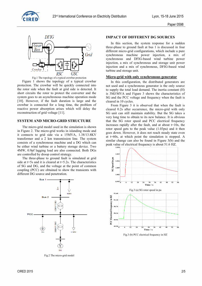
Fig.1 The topology of a typical crowbar protection
Figure 1 shows the topology of a typical crowbar
protection. The crowbar will be quickly connected into
the rotor side when the fault at grid side is detected. It
short circuits the rotor to protect the converter and the
system goes to an asynchronous machine operation mode
[10]. However, if the fault duration is large and the
crowbar is connected for a long time, the problem of
reactive power absorption arises which will delay the
reconstruction of grid voltage [11].
SYSTEM AND MICRO-GRID STRUCTURE
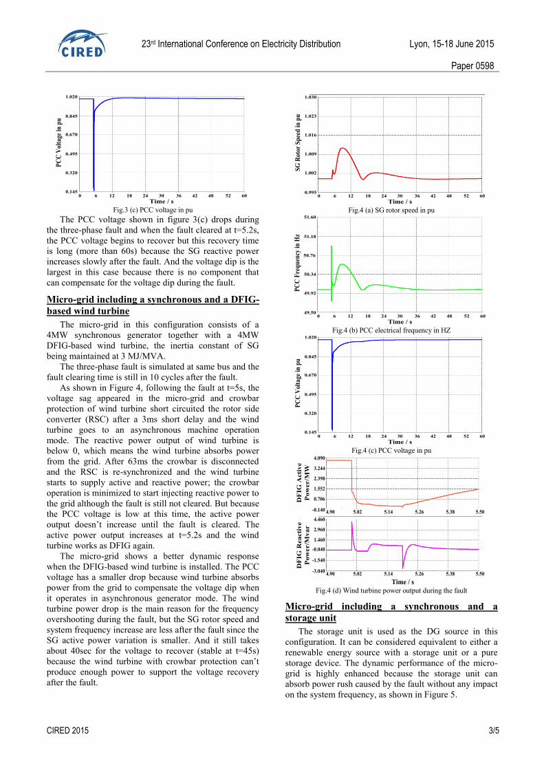
The micro-grid model used in the simulation is shown
in Figure 2. The micro-grid works in islanding mode and
it connects to grid side via a 15MVA, 1.38/13.8KV
transformer and a 2 km transmission line. The system
consists of a synchronous machine and a DG which can
be either wind turbine or a battery storage device. Two
4MW, 0.9pf lagging load are also connected. Both DGs
are controlled by droop control strategy.
The three-phase to ground fault is simulated at grid
side at t=5s and it is cleared at t=5.2s. The characteristics
of SG and DG, and the voltage at the point of common
coupling (PCC) are obtained to show the transients with
different DG source and penetration.
Fig.2 The micro-grid model
IMPACT OF DIFFERENT DG SOURCES
In this section, the system response for a sudden
three-phase to ground fault at bus 1 is discussed in four
different micro-grid configurations, which include a pure
synchronous machine power injection, a mix of
synchronous and DFIG-based wind turbine power
injection, a mix of synchronous and storage unit power
injection and a mix of synchronous, DFIG-based wind
turbine and storage unit.
Micro-grid with only synchronous generator
In this configuration, the distributed generators are
not used and a synchronous generator is the only source
to supply the total load demand. The inertia constant (H)
is 3MJ/MVA and Figure 3 shows the characteristics of
SG and the PCC voltage and frequency when the fault is
cleared in 10 cycles.
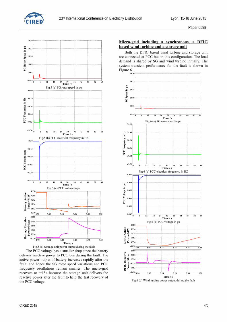
From Figure 3 it is observed that when the fault is
cleared 0.2s after occurrence, the micro-grid with only
SG unit can still maintain stability. But the SG takes a
very long time to obtain to its new balance. It is obvious
that the SG rotor speed and PCC electrical frequency
increases rapidly after the fault, and at about t=10s, the
rotor speed gets to the peak value (1.03pu) and it then
goes down. However, it does not reach steady state even
at t=60s, at which point the simulation is stopped. A
similar change can also be found in Figure 3(b) and the
peak value of electrical frequency is about 51.6 HZ.
0 6 12 18 24 30 36 42 48 52 600.995
1.002
1.009
1.016
1.023
1.030
Time / s
SG
Sp
eed
in
pu
Fig.3 (a) SG rotor speed in pu
0 6 12 18 24 30 36 42 48 52 60
Time / s
49.50
49.92
50.34
50.76
51.18
51.60
PC
C E
lect
rica
l Fre
qu
ency
in H
Z
Fig.3 (b) PCC electrical frequency in HZ
23rd International Conference on Electricity Distribution Lyon, 15-18 June 2015
Paper 0598
CIRED 2015 3/5
0 6 12 18 24 30 36 42 48 52 60
Time / s
PC
C V
olta
ge i
n p
u
0.145
0.320
0.495
0.670
0.845
1.020
Fig.3 (c) PCC voltage in pu
The PCC voltage shown in figure 3(c) drops during
the three-phase fault and when the fault cleared at t=5.2s,
the PCC voltage begins to recover but this recovery time
is long (more than 60s) because the SG reactive power
increases slowly after the fault. And the voltage dip is the
largest in this case because there is no component that
can compensate for the voltage dip during the fault.
Micro-grid including a synchronous and a DFIG-
based wind turbine
The micro-grid in this configuration consists of a
4MW synchronous generator together with a 4MW
DFIG-based wind turbine, the inertia constant of SG
being maintained at 3 MJ/MVA.
The three-phase fault is simulated at same bus and the
fault clearing time is still in 10 cycles after the fault.
As shown in Figure 4, following the fault at t=5s, the
voltage sag appeared in the micro-grid and crowbar
protection of wind turbine short circuited the rotor side
converter (RSC) after a 3ms short delay and the wind
turbine goes to an asynchronous machine operation
mode. The reactive power output of wind turbine is
below 0, which means the wind turbine absorbs power
from the grid. After 63ms the crowbar is disconnected
and the RSC is re-synchronized and the wind turbine
starts to supply active and reactive power; the crowbar
operation is minimized to start injecting reactive power to
the grid although the fault is still not cleared. But because
the PCC voltage is low at this time, the active power
output doesn’t increase until the fault is cleared. The
active power output increases at t=5.2s and the wind
turbine works as DFIG again.
The micro-grid shows a better dynamic response
when the DFIG-based wind turbine is installed. The PCC
voltage has a smaller drop because wind turbine absorbs
power from the grid to compensate the voltage dip when
it operates in asynchronous generator mode. The wind
turbine power drop is the main reason for the frequency
overshooting during the fault, but the SG rotor speed and
system frequency increase are less after the fault since the
SG active power variation is smaller. And it still takes
about 40sec for the voltage to recover (stable at t=45s)
because the wind turbine with crowbar protection can’t
produce enough power to support the voltage recovery
after the fault.
0 6 12 18 24 30 36 42 48 52 60
Time / s
SG
Rot
or S
pee
d i
n p
u
0.995
1.002
1.009
1.016
1.023
1.030
Fig.4 (a) SG rotor speed in pu
0 6 12 18 24 30 36 42 48 52 60
Time / s
PC
C F
req
uen
cy i
n H
z
49.50
49.92
50.34
50.76
51.18
51.60
Fig.4 (b) PCC electrical frequency in HZ
0 6 12 18 24 30 36 42 48 52 60
Time / s
PC
C V
olta
ge i
n p
u
1.020
0.845
0.670
0.495
0.320
0.145
Fig.4 (c) PCC voltage in pu
4.90 5.02 5.14 5.26 5.38 5.50
4.90 5.02 5.14 5.26 5.38 5.50
Time / s
DF
IG A
cti
ve
Po
wer/M
W
DF
IG R
ea
cti
ve
Po
wer/M
va
r
-3.040
-1.540
-0.040
1.460
2.960
4.460
-0.140
0.706
1.552
2.398
3.244
4.090
Fig.4 (d) Wind turbine power output during the fault
Micro-grid including a synchronous and a
storage unit
The storage unit is used as the DG source in this
configuration. It can be considered equivalent to either a
renewable energy source with a storage unit or a pure
storage device. The dynamic performance of the micro-
grid is highly enhanced because the storage unit can
absorb power rush caused by the fault without any impact
on the system frequency, as shown in Figure 5.
23rd International Conference on Electricity Distribution Lyon, 15-18 June 2015
Paper 0598
CIRED 2015 4/5
0 6 12 18 24 30 36 42 48 52 60 Time / s
SG
Ro
tor
Sp
eed
in
pu
0.995
1.002
1.009
1.016
1.023
1.030
Fig.5 (a) SG rotor speed in pu
0 6 12 18 24 30 36 42 48 52 60
Time / s
PC
C F
req
uen
cy i
n H
z
49.50
49.92
50.34
50.76
51.18
51.60
Fig.5 (b) PCC electrical frequency in HZ
Time / s0 6 12 18 24 30 36 42 48 52 60
PC
C V
olta
ge i
n p
u
0.145
0.320
0.495
0.670
0.845
1.020
Fig.5 (c) PCC voltage in pu
4.90 5.02 5.14 5.26 5.38 5.50
4.90 5.02 5.14 5.26 5.38 5.50
Time / s
Ba
ttery
Acti
ve
Po
wer/M
W
Ba
ttery
Rea
cti
ve
Po
wer/M
va
r
-0.130
0.516
1.162
1.808
2.454
3.100
0.310
1.082
1.854
2.626
3.398
4.170
Fig.5 (d) Storage unit power output during the fault
The PCC voltage has a smaller drop since the battery
delivers reactive power to PCC bus during the fault. The
active power output of battery increases rapidly after the
fault, and hence the SG rotor speed variations and PCC
frequency oscillations remain smaller. The micro-grid
recovers at t=15s because the storage unit delivers the
reactive power after the fault to help the fast recovery of
the PCC voltage.
Micro-grid including a synchronous, a DFIG
based wind turbine and a storage unit
Both the DFIG based wind turbine and storage unit
are connected at PCC bus in this configuration. The load
demand is shared by SG and wind turbine initially. The
system transient performance for the fault is shown in
Figure 6.
0 6 12 18 24 30 36 42 48 52 60
Time / s
SG
Sp
eed
in
pu
0.995
1.002
1.009
1.016
1.023
1.030
Fig.6 (a) SG rotor speed in pu
Time / s0 6 12 18 24 30 36 42 48 52 60
PC
C F
req
uen
cy i
n H
z
49.50
49.92
50.34
50.76
51.18
51.60
Fig.6 (b) PCC electrical frequency in HZ
0 6 12 18 24 30 36 42 48 52 60
Time / s
PC
C V
olta
ge i
n p
u
0.145
0.320
0.495
0.670
0.845
1.020
Fig.6 (c) PCC voltage in pu
4.90 5.02 5.14 5.26 5.38 5.50
4.90 5.02 5.14 5.26 5.38 5.50
Time / s
DF
IG A
cti
ve
Po
wer/M
W
DF
IG R
ea
cti
ve
Po
wer/M
va
r
-3.650
-1.982
-0.314
1.354
3.002
4.690
-0.050
0.776
1.602
2.428
3.254
4.080
Fig.6 (d) Wind turbine power output during the fault
23rd International Conference on Electricity Distribution Lyon, 15-18 June 2015
Paper 0598
CIRED 2015 5/5
4.90 5.02 5.14 5.26 5.38 5.50
4.90 5.02 5.14 5.26 5.38 5.50
Ba
ttery
Acti
ve
Po
wer/M
W
Ba
ttery
Rea
cti
ve
Po
wer/M
va
r
Time / s
-0.140
0.484
1.108
1.732
2.356
2.980
-1.530
-1.208
-0.886
-0.564
-0.242
0.080
Fig.6 (e) Storage unit power output during the fault
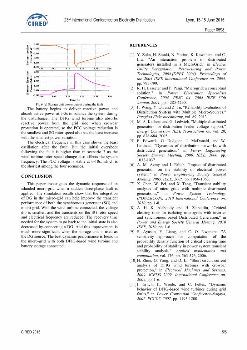
The battery begins to deliver reactive power and
absorb active power at t=5s to balance the system during
the disturbance. The DFIG wind turbine also absorbs
reactive power from the grid side when crowbar
protection is operated, so the PCC voltage reduction is
the smallest and SG rotor speed also has the least increase
with the smallest power variation.
The electrical frequency in this case shows the least
oscillation after the fault. But the initial overshoot
following the fault is higher than in scenario 3 as the
wind turbine rotor speed change also affects the system
frequency. The PCC voltage is stable at t=10s, which is
the shortest among the four scenarios.
CONCLUSION
This paper investigates the dynamic response of an
islanded micro-grid when a sudden three-phase fault is
applied. The simulation results show that the integration
of DG in the micro-grid can help improve the transient
performance of both the synchronous generator (SG) and
micro-grid. With the wind turbine connected, the voltage
dip is smaller, and the transients on the SG rotor speed
and electrical frequency are reduced. The recovery time
needed for the system to go back to the initial state is also
decreased by connecting a DG. And this improvement is
much more significant when the storage unit is used as
the DG source. The best dynamic performance is found in
the micro-grid with both DFIG-based wind turbine and
battery storage connected.
REFERENCES
[1] Y. Zoka, H. Sasaki, N. Yorino, K. Kawahara, and C.
Liu, "An interaction problem of distributed
generators installed in a MicroGrid," in Electric
Utility Deregulation, Restructuring and Power
Technologies, 2004.(DRPT 2004). Proceedings of
the 2004 IEEE International Conference on, 2004,
pp. 795-799.
[2] R. H. Lasseter and P. Paigi, "Microgrid: a conceptual
solution," in Power Electronics Specialists
Conference, 2004. PESC 04. 2004 IEEE 35th
Annual, 2004, pp. 4285-4290.
[3] F. Wang, Y. Qi, and Z. Fu, "Reliability Evaluation of
Distribution System with Multiple Micro-Sources,"
Przegląd Elektrotechniczny, vol. 89, 2013.
[4] M. A. Kashem and G. Ledwich, "Multiple distributed
generators for distribution feeder voltage support,"
Energy Conversion, IEEE Transactions on, vol. 20,
pp. 676-684, 2005.
[5] F. Edwards, G. Dudgeon, J. McDonald, and W.
Leithead, "Dynamics of distribution networks with
distributed generation," in Power Engineering
Society Summer Meeting, 2000. IEEE, 2000, pp.
1032-1037.
[6] A. M. Azmy and I. Erlich, "Impact of distributed
generation on the stability of electrical power
system," in Power Engineering Society General
Meeting, 2005. IEEE, 2005, pp. 1056-1063.
[7] X. Chen, W. Pei, and X. Tang, "Transient stability
analyses of micro-grids with multiple distributed
generations," in Power System Technology
(POWERCON), 2010 International Conference on,
2010, pp. 1-8.
[8] A. H. K. Alaboudy and H. Zeineldin, "Critical
clearing time for isolating microgrids with inverter
and synchronous based Distributed Generation," in
Power and Energy Society General Meeting, 2010
IEEE, 2010, pp. 1-6.
[9] S. Ayasun, Y. Liang, and C. O. Nwankpa, "A
sensitivity approach for computation of the
probability density function of critical clearing time
and probability of stability in power system transient
stability analysis," Applied mathematics and
computation, vol. 176, pp. 563-576, 2006.
[10] H. Zhou, G. Yang, and D. Li, "Short circuit current
analysis of DFIG wind turbines with crowbar
protection," in Electrical Machines and Systems,
2009. ICEMS 2009. International Conference on,
2009, pp. 1-6.
[11] I. Erlich, H. Wrede, and C. Feltes, "Dynamic
behavior of DFIG-based wind turbines during grid
faults," in Power Conversion Conference-Nagoya,
2007. PCC'07, 2007, pp. 1195-1200.