Embed Size (px)
Citation preview
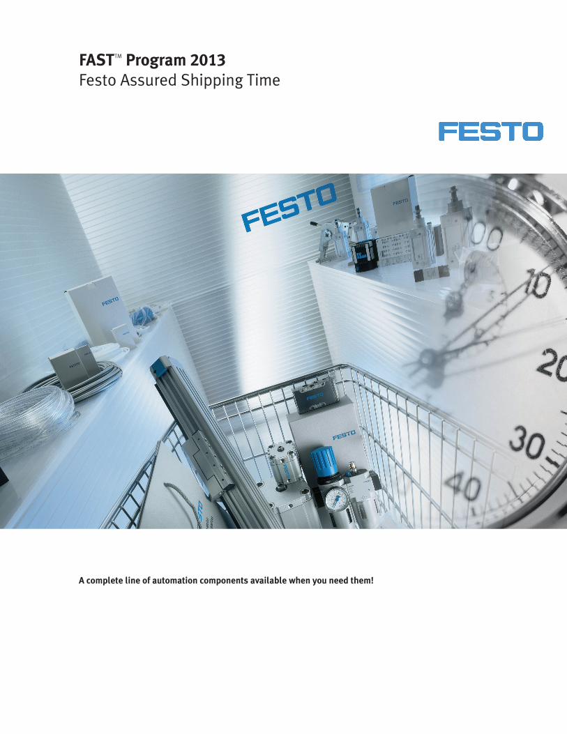
FASTTM Program 2013Festo Assured Shipping Time
A complete line of automation components available when you need them!
• Piston Rod Cylinders• Guided Piston Rod Actuators• Rodless Actuators• Rotary Actuators
• Manual/Mechanical Valves• Stand Alone Valves• Valve Manifolds
• Filter/Regulator-Lubricators• Filter Regulators• Pressure Regulators and Accessories• Filters• Lubricators• On/Off Valves and Soft-start Valves• Distribution Blocks
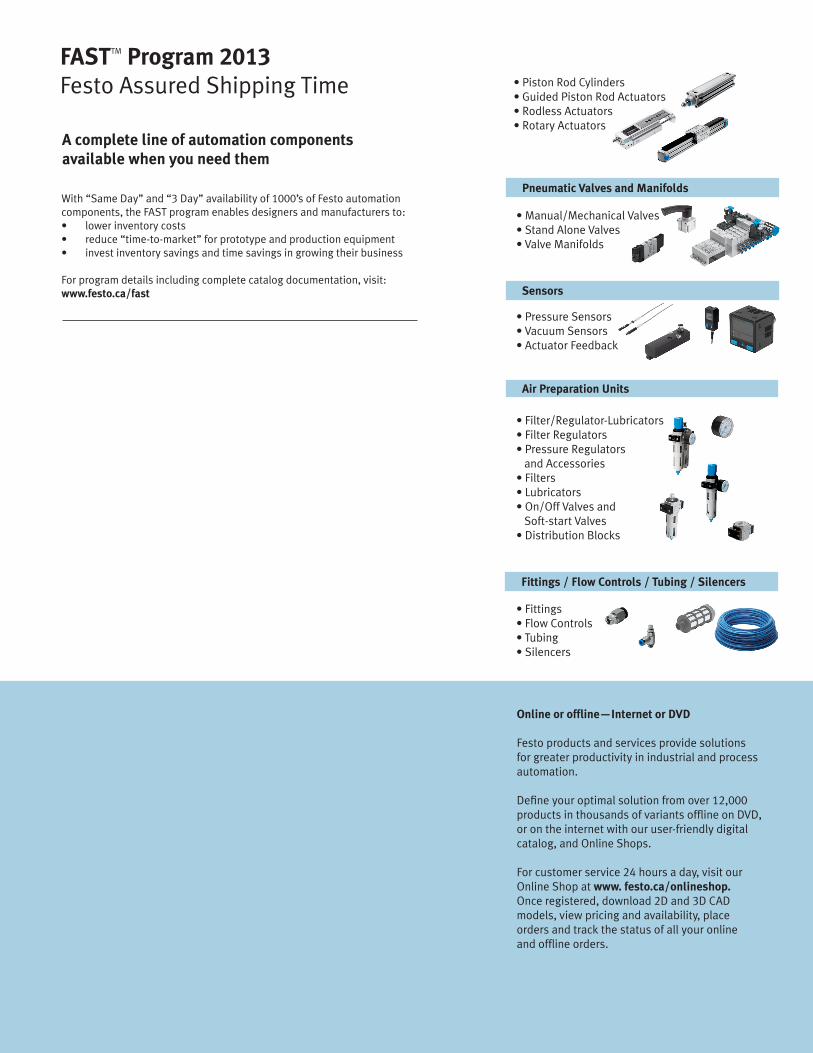
FASTTM Program 2013Festo Assured Shipping Time
A complete line of automation componentsavailable when you need them
With “Same Day” and “3 Day” availability of 1000’s of Festo automation components, the FAST program enables designers and manufacturers to:• lower inventory costs• reduce “time-to-market” for prototype and production equipment• invest inventory savings and time savings in growing their business
For program details including complete catalog documentation, visit:www.festo.ca/fast
Pneumatic Valves and Manifolds
Sensors
Air Preparation Units
Fittings / Flow Controls / Tubing / Silencers
• Pressure Sensors• Vacuum Sensors• Actuator Feedback
• Fittings• Flow Controls• Tubing• Silencers
Online or offline—Internet or DVD
Festo products and services provide solutionsfor greater productivity in industrial and processautomation.
Define your optimal solution from over 12,000products in thousands of variants offline on DVD,or on the internet with our user-friendly digitalcatalog, and Online Shops.
For customer service 24 hours a day, visit ourOnline Shop at www. festo.ca/onlineshop.Once registered, download 2D and 3D CADmodels, view pricing and availability, placeorders and track the status of all your onlineand offline orders.
FAST Program Catalog – Subject to change – 2012/1088 � Internet: www.festo.com/catalog/...
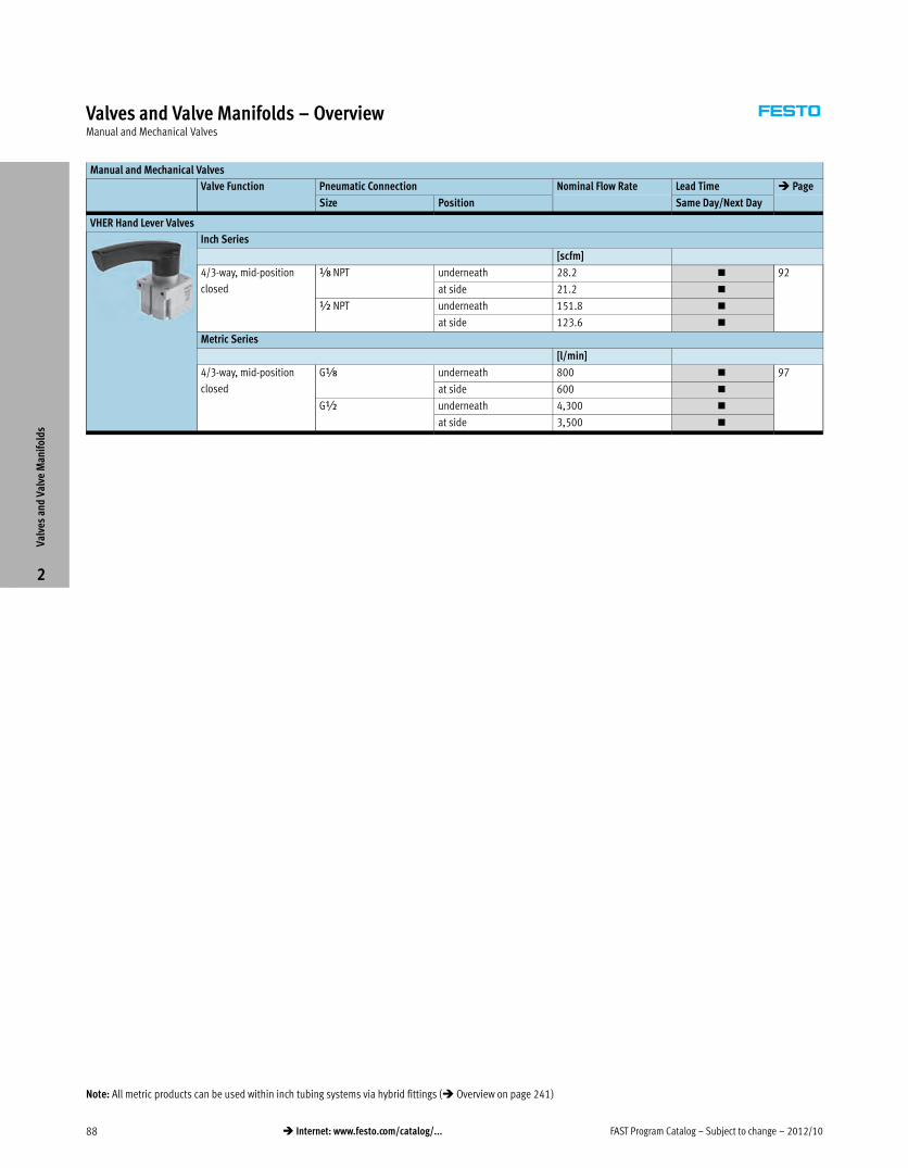
Valves and Valve Manifolds – OverviewManual and Mechanical Valves
Manual and Mechanical Valves
Valve Function Pneumatic Connection Nominal Flow Rate Lead Time � Page
Size Position Same Day/Next Day
VHER Hand Lever Valves
Inch Series
[scfm]
4/3-way, mid-position
closed
x NPT underneath 28.2 � 92
at side 21.2 �
½ NPT underneath 151.8 �
at side 123.6 �
Metric Series
[l/min]
4/3-way, mid-position
closed
Gx underneath 800 � 97
at side 600 �
G½ underneath 4,300 �
at side 3,500 �
Valv
es a
nd V
alve
Man
ifol
ds
2
Note: All metric products can be used within inch tubing systems via hybrid fittings (� Overview on page 241)
2012/10 – Subject to change – FAST Program Catalog 89� Internet: www.festo.com/catalog/...
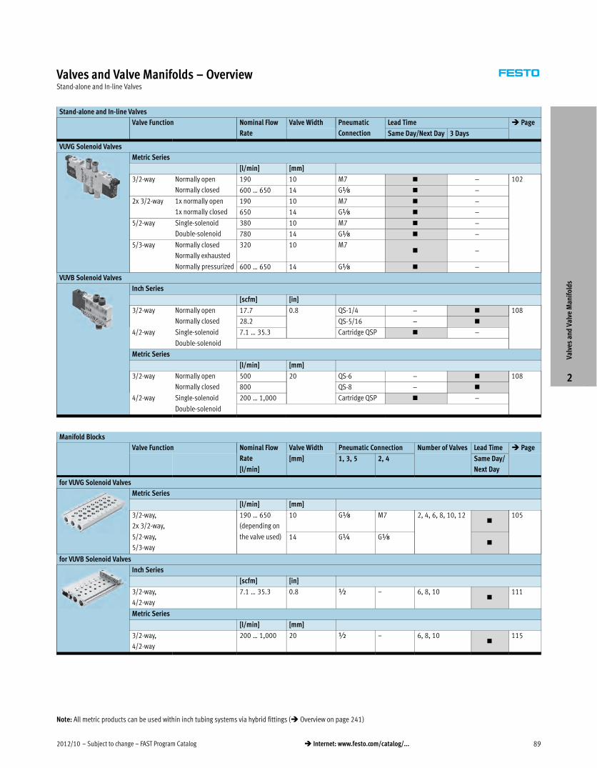
Valves and Valve Manifolds – OverviewStand-alone and In-line Valves
Stand-alone and In-line Valves
Valve Function Nominal Flow
Rate
Valve Width Pneumatic
Connection
Lead Time � Page
Same Day/Next Day 3 Days
VUVG Solenoid Valves
Metric Series
[l/min] [mm]
3/2-way Normally open
Normally closed
190 10 M7 � – 102
600 … 650 14 Gx � –
2x 3/2-way 1x normally open
1x normally closed
190 10 M7 � –
650 14 Gx � –
5/2-way Single-solenoid
Double-solenoid
380 10 M7 � –
780 14 Gx � –
5/3-way Normally closed
Normally exhausted
Normally pressurized
320 10 M7� –
600 … 650 14 Gx � –
VUVB Solenoid Valves
Inch Series
[scfm] [in]
3/2-way Normally open
Normally closed
17.7 0.8 QS-1/4 – � 108
28.2 QS-5/16 – �
4/2-way Single-solenoid 7.1 … 35.3 Cartridge QSP � –
Double-solenoid
Metric Series
[l/min] [mm]
3/2-way Normally open
Normally closed
500 20 QS-6 – � 108
800 QS-8 – �
4/2-way Single-solenoid 200 … 1,000 Cartridge QSP � –
Double-solenoid
Manifold Blocks
Valve Function Nominal Flow
Rate
[l/min]
Valve Width Pneumatic Connection Number of Valves Lead Time � Page
[mm] 1, 3, 5 2, 4 Same Day/
Next Day
for VUVG Solenoid Valves
Metric Series
[l/min] [mm]
3/2-way,
2x 3/2-way,
5/2-way,
5/3-way
190 … 650
(depending on
the valve used)
10 Gx M7 2, 4, 6, 8, 10, 12�
105
14 G¼ Gx�
for VUVB Solenoid Valves
Inch Series
[scfm] [in]
3/2-way,
4/2-way
7.1 … 35.3 0.8 ½ – 6, 8, 10�
111
Metric Series
[l/min] [mm]
3/2-way,
4/2-way
200 … 1,000 20 ½ – 6, 8, 10�
115
Valv
es a
nd V
alve
Man
ifol
ds
2
Note: All metric products can be used within inch tubing systems via hybrid fittings (� Overview on page 241)
FAST Program Catalog – Subject to change – 2012/1090 � Internet: www.festo.com/catalog/...
Valves and Valve Manifolds – OverviewValve Manifolds
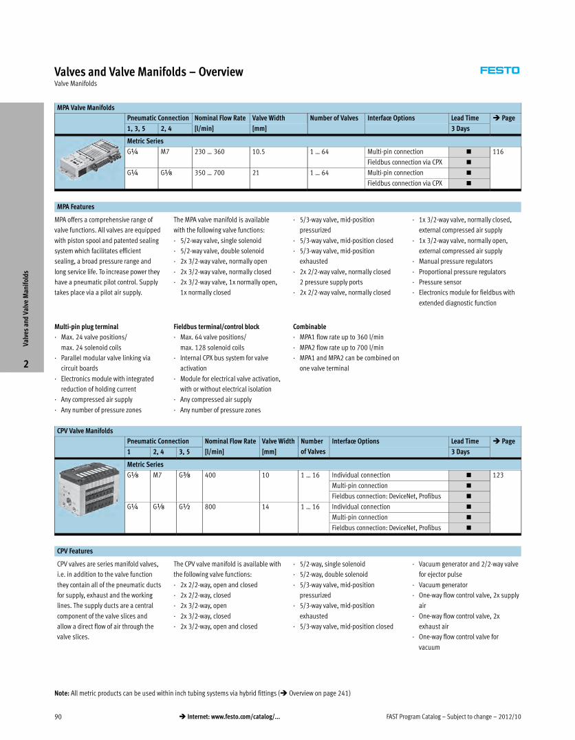
MPA Valve Manifolds
Pneumatic Connection Nominal Flow Rate Valve Width Number of Valves Interface Options Lead Time � Page
1, 3, 5 2, 4 [l/min] [mm] 3 Days
Metric Series
G¼ M7 230 … 360 10.5 1 … 64 Multi-pin connection � 116
Fieldbus connection via CPX �
G¼ Gx 350 … 700 21 1 … 64 Multi-pin connection �
Fieldbus connection via CPX �
MPA Features
MPA offers a comprehensive range of
valve functions. All valves are equipped
with piston spool and patented sealing
system which facilitates efficient
sealing, a broad pressure range and
long service life. To increase power they
have a pneumatic pilot control. Supply
takes place via a pilot air supply.
The MPA valve manifold is available
with the following valve functions:
· 5/2-way valve, single solenoid
· 5/2-way valve, double solenoid
· 2x 3/2-way valve, normally open
· 2x 3/2-way valve, normally closed
· 2x 3/2-way valve, 1x normally open,
1x normally closed
· 5/3-way valve, mid-position
pressurized
· 5/3-way valve, mid-position closed
· 5/3-way valve, mid-position
exhausted
· 2x 2/2-way valve, normally closed
2 pressure supply ports
· 2x 2/2-way valve, normally closed
· 1x 3/2-way valve, normally closed,
external compressed air supply
· 1x 3/2-way valve, normally open,
external compressed air supply
· Manual pressure regulators
· Proportional pressure regulators
· Pressure sensor
· Electronics module for fieldbus with
extended diagnostic function
Multi-pin plug terminal
· Max. 24 valve positions/
max. 24 solenoid coils
· Parallel modular valve linking via
circuit boards
· Electronics module with integrated
reduction of holding current
· Any compressed air supply
· Any number of pressure zones
Fieldbus terminal/control block
· Max. 64 valve positions/
max. 128 solenoid coils
· Internal CPX bus system for valve
activation
· Module for electrical valve activation,
with or without electrical isolation
· Any compressed air supply
· Any number of pressure zones
Combinable
· MPA1 flow rate up to 360 l/min
· MPA2 flow rate up to 700 l/min
· MPA1 and MPA2 can be combined on
one valve terminal
CPV Valve Manifolds
Pneumatic Connection Nominal Flow Rate Valve Width Number
of Valves
Interface Options Lead Time � Page
1 2, 4 3, 5 [l/min] [mm] 3 Days
Metric Series
Gx M7 Gy 400 10 1 … 16 Individual connection � 123
Multi-pin connection �
Fieldbus connection: DeviceNet, Profibus �
G¼ Gx G½ 800 14 1 … 16 Individual connection �
Multi-pin connection �
Fieldbus connection: DeviceNet, Profibus �
CPV Features
CPV valves are series manifold valves,
i.e. in addition to the valve function
they contain all of the pneumatic ducts
for supply, exhaust and the working
lines. The supply ducts are a central
component of the valve slices and
allow a direct flow of air through the
valve slices.
The CPV valve manifold is available with
the following valve functions:
· 2x 2/2-way, open and closed
· 2x 2/2-way, closed
· 2x 3/2-way, open
· 2x 3/2-way, closed
· 2x 3/2-way, open and closed
· 5/2-way, single solenoid
· 5/2-way, double solenoid
· 5/3-way valve, mid-position
pressurized
· 5/3-way valve, mid-position
exhausted
· 5/3-way valve, mid-position closed
· Vacuum generator and 2/2-way valve
for ejector pulse
· Vacuum generator
· One-way flow control valve, 2x supply
air
· One-way flow control valve, 2x
exhaust air
· One-way flow control valve for
vacuum
Valv
es a
nd V
alve
Man
ifol
ds
2
Note: All metric products can be used within inch tubing systems via hybrid fittings (� Overview on page 241)

2012/10 – Subject to change – FAST Program Catalog 91� Internet: www.festo.com/catalog/...
Valves and Valve Manifolds – OverviewValve Manifolds
VTSA/VTSA-F Valve Manifolds
Pneumatic Connection Nominal Flow Rate Valve Width Number
of Valves
Interface Options Lead Time � Page
1 2, 4 3, 5 3 Days
Inch Series
[scfm] [in]
½ NPT x NPT ½ NPT up to 24.7 0.71 1 … 32 Multi-pin connection � 130
Fieldbus connection via CPX �
½ NPT ¼ NPT ½ NPT up to 49.4 1.02 1 … 32 Multi-pin connection �
Fieldbus connection via CPX �
½ NPT y NPT ½ NPT up to 53 1.65 1 … 32 Multi-pin connection �
Fieldbus connection via CPX �
¾NPT ½NPT ¾NPT up to 102 2.05 1 … 32 Multi-pin connection �
Fieldbus connection via CPX �
Metric Series
[l/min] [mm]
G½ Gx G½ up to 700 18 1 … 32 Multi-pin connection � 137
Fieldbus connection via CPX �
G½ G¼ G½ up to 1,400 26 1 … 32 Multi-pin connection �
Fieldbus connection via CPX �
G½ Gy G½ up to 1,500 42 1 … 32 Multi-pin connection �
Fieldbus connection via CPX �
G¾ G½ G¾ up to 2,900 52 1 … 32 Multi-pin connection �
Fieldbus connection via CPX �
VTSA/VTSA-F Features
The flexible combination of 4 different
valve sizes on a single valve terminal
allows adaptation to different flow
requirements.
Adjustment of regulators without tools.
And with the standardized operating
direction from above for regulators and
valves, this terminal offers the solution
to just about every requirement in terms
of functionality.
What about fieldbus and modular I/Os?
Connection to the modern CPX terminal
is an added benefit. This level of
freedom, modularity, and versatility is
unmatched in any valve manifold
solution.
The CPX-MMI-1 hand-held device
explains errors in plain text and helps
expedite troubleshooting, reducing
downtimes. Remote maintenance via
Ethernet/Internet eliminates the need
for servicing at night and over long
distances, which can often be very
expensive. The on-site intelligence
permits CMS (Condition Monitoring
Systems) for each valve and statistical
error logging with history and
timestamp.
The VTSA valve manifold is available
with the following valve functions:
· 5/2-way valve
– Single solenoid valve,
pneumatic/spring return
– Double solenoid valve
– Double solenoid valve with
dominant signal
· 2x 3/2-way valve, single solenoid
– Normally open
– Normally open, reversible
– Normally closed
– Normally closed, reversible
– 1x normally open,
1x normally closed
– 1x normally open,
1x normally closed, reversible
· 5/3-way valve
– Mid-position pressurized
– Mid-position closed
– Mid-position exhausted
· Soft-start valve
– with internal or external pilot air
– without proximity sensor
– with proximity sensor PNP or NPNVa
lves
and
Val
ve M
anif
olds
2
Note: All metric products can be used within inch tubing systems via hybrid fittings (� Overview on page 241)
FAST Program Catalog – Subject to change – 2012/1092 � Internet: www.festo.com/catalog/...
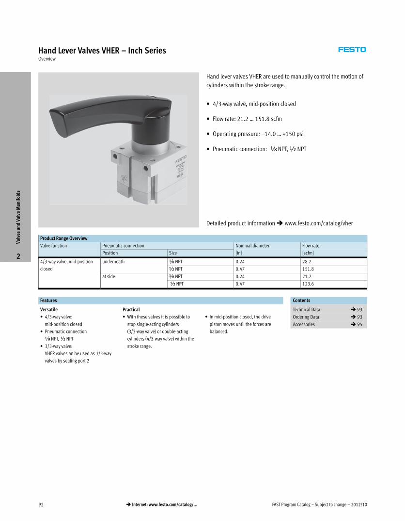
Hand Lever Valves VHER – Inch SeriesOverview
Hand lever valves VHER are used to manually control the motion of
cylinders within the stroke range.
� 4/3-way valve, mid-position closed
� Flow rate: 21.2 … 151.8 scfm
� Operating pressure: –14.0 … +150 psi
� Pneumatic connection: x NPT, ½ NPT
Product Range Overview
Valve function Pneumatic connection Nominal diameter Flow rate
Position Size [in] [scfm]
4/3-way valve, mid-position
closed
underneath x NPT 0.24 28.2
½ NPT 0.47 151.8
at side x NPT 0.24 21.2
½ NPT 0.47 123.6
Features Contents
Versatile
� 4/3-way valve:
mid-position closed
� Pneumatic connection
x NPT, ½ NPT
� 3/3-way valve:
VHER valves an be used as 3/3-way
valves by sealing port 2
Practical
� With these valves it is possible to
stop single-acting cylinders
(3/3-way valve) or double-acting
cylinders (4/3-way valve) within the
stroke range.
� In mid-position closed, the drive
piston moves until the forces are
balanced.
Technical Data � 93
Ordering Data � 93
Accessories � 95
Valv
es a
nd V
alve
Man
ifol
ds
2
Detailed product information � www.festo.com/catalog/vher
2012/10 – Subject to change – FAST Program Catalog 93� Internet: www.festo.com/catalog/...
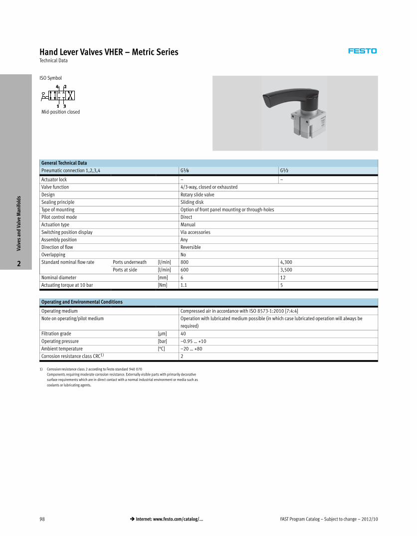
Hand Lever Valves VHER – Inch SeriesTechnical Data
ISO Symbol
Mid-position closed
General Technical Data
Pneumatic connection 1,2,3,4 x NPT ½ NPT
Valve function 4/3-way, closed or exhausted
Design Rotary slide valve
Sealing principle Sliding disk
Type of mounting Option of front panel mounting or through-holes
Pilot control mode Direct
Actuation type Manual
Actuating lever Metal
Switching position display Via accessories
Assembly position Any
Direction of flow Reversible
Overlapping No
Standard nominal flow rate Ports underneath [scfm] 28.2 151.8
Ports at side [scfm] 21.2 123.6
Nominal diameter [in] 0.24 0.47
Actuating torque at 10 bar [lbf-in] 9.74 44.25
Operating and Environmental Conditions
Operating medium Compressed air in accordance with ISO 8573-1:2010 [7:4:4]
Note on operating/pilot medium Operation with lubricated medium possible (in which case lubricated operation will always be
required)
Filtration grade [μm] 40
Operating pressure [psi] –14 … +150
Ambient temperature [°F] –4 … +176
Corrosion resistance class CRC1) 2*
1) Corrosion resistance class 2 according to Festo standard 940 070
Components requiring moderate corrosion resistance. Externally visible parts with primarily decorative
surface requirements which are in direct contact with a normal industrial environment or media such as
coolants or lubricating agents.
Valv
es a
nd V
alve
Man
ifol
ds
2
FAST Program Catalog – Subject to change – 2012/1094 � Internet: www.festo.com/catalog/...
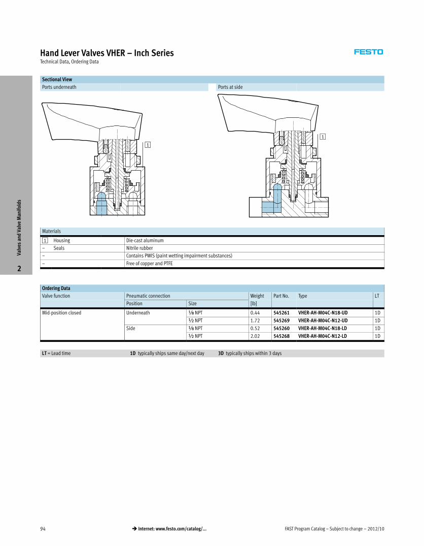
Hand Lever Valves VHER – Inch SeriesTechnical Data, Ordering Data
Sectional View
Ports underneath Ports at side
1
1
Materials
1 Housing Die-cast aluminum
– Seals Nitrile rubber
– Contains PWIS (paint wetting impairment substances)
– Free of copper and PTFE
Ordering Data
Valve function Pneumatic connection Weight Part No. Type LT
Position Size [lb]
Mid-position closed Underneath Á NPT 0.44 545261 VHER-AH-M04C-N18-UD 1D
½ NPT 1.72 545269 VHER-AH-M04C-N12-UD 1D
Side Á NPT 0.52 545260 VHER-AH-M04C-N18-LD 1D
½ NPT 2.02 545268 VHER-AH-M04C-N12-LD 1D
LT = Lead time 1D typically ships same day/next day 3D typically ships within 3 days
Valv
es a
nd V
alve
Man
ifol
ds
2
2012/10 – Subject to change – FAST Program Catalog 95� Internet: www.festo.com/catalog/...
Hand Lever Valves VHER – Inch SeriesAccessories
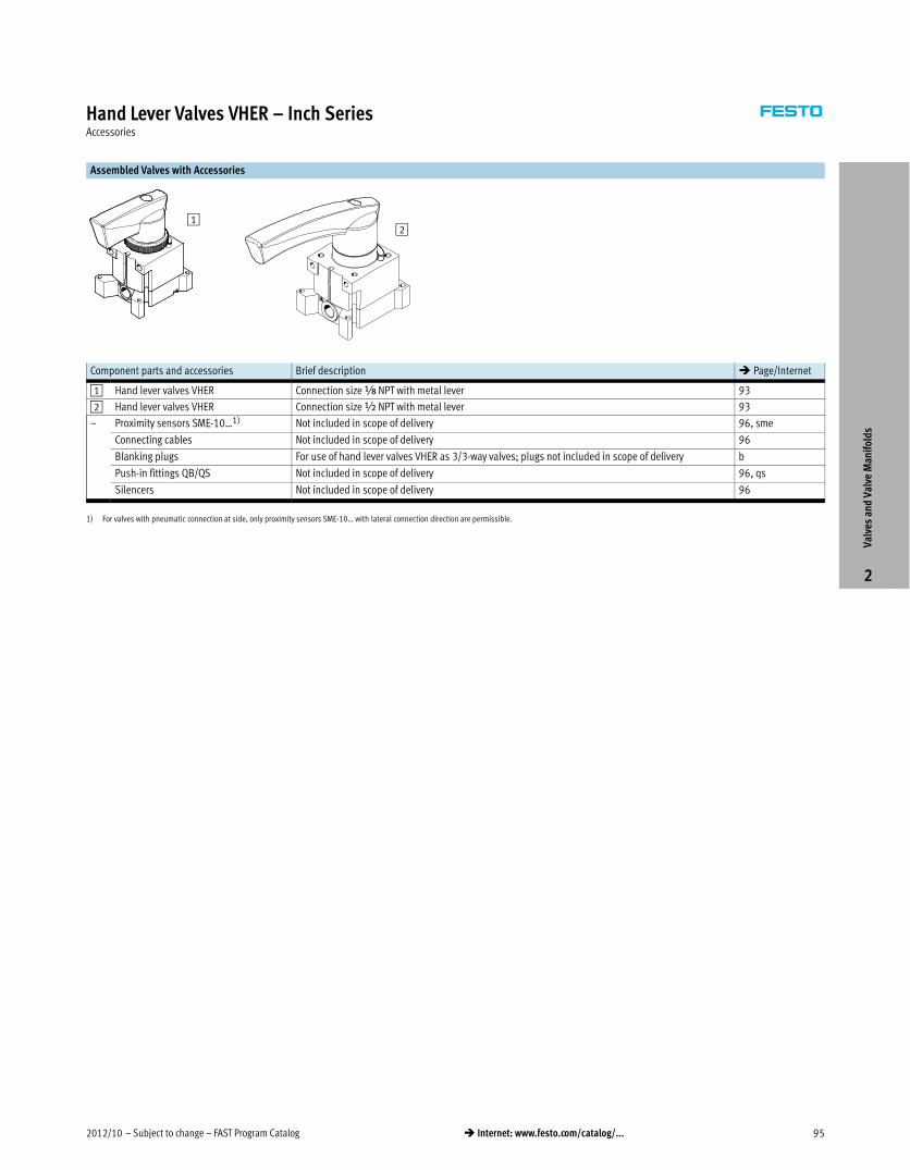
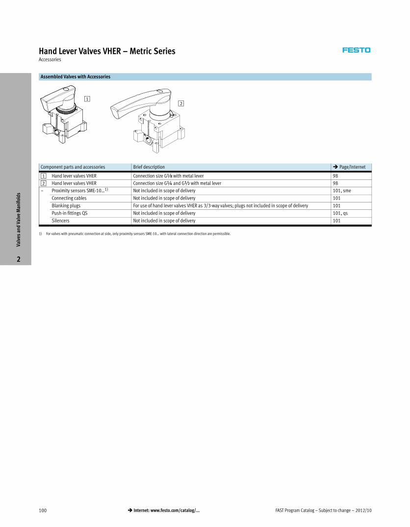
Assembled Valves with Accessories
12
Component parts and accessories Brief description � Page/Internet
1 Hand lever valves VHER Connection size x NPT with metal lever 93
2 Hand lever valves VHER Connection size ½ NPT with metal lever 93
– Proximity sensors SME-10…1) Not included in scope of delivery 96, sme
Connecting cables Not included in scope of delivery 96
Blanking plugs For use of hand lever valves VHER as 3/3-way valves; plugs not included in scope of delivery b
Push-in fittings QB/QS Not included in scope of delivery 96, qs
Silencers Not included in scope of delivery 96
1) For valves with pneumatic connection at side, only proximity sensors SME-10… with lateral connection direction are permissible.
Valv
es a
nd V
alve
Man
ifol
ds
2

FAST Program Catalog – Subject to change – 2012/1096 � Internet: www.festo.com/catalog/...
Hand Lever Valves VHER – Inch SeriesAccessories
Ordering data
Switching output Electrical connection Cable
length
[m]
Weight
[g]
Part No. Type
Cable Cable with plug, rotatable
thread
N/O contact
Contacting,
bipolar
2-wire – 2.5 14.6 551369 SME-10M-ZS-24V-E-2,5-L-OE
– M8x1, 3-pin 0.3 6.7 551367 SME-10M-DS-24V-E-0,3-L-M8D
Ordering Data – Connecting Cables Technical Data � www.festo.com/catalog/nebu
Electrical connection, left Electrical connection, right Cable length Part No. Type
[ft]
Straight socket, M8x1, 3-pin Cable, open end, 3-wire 8.2 541333 NEBU-M8G3-K-2.5-LE3
Ordering Data – Permissible Push-in Fittings QB/QS1)
x NPT ½ NPT
Part No. Type Part No. Type
Pneumatic connection underneath
533271 QB-x-5/32-U 533283 QB-½-3/8-U
533274 QB-x-5/16-U 533284 QB-½-½-U
1) Scope of delivery 10 pieces
Ordering Data – Permissible Silencers
x NPT ½ NPT
Part No. Type Part No. Type
12638 U-x-B-NPT 12741 U-½-B-NPT
Valv
es a
nd V
alve
Man
ifol
ds
2
Lead Time LT for all products on this page: 1D typically ships same day/next day
2012/10 – Subject to change – FAST Program Catalog 97� Internet: www.festo.com/catalog/...
Hand Lever Valves VHER – Metric SeriesOverview
Hand lever valves VHER are used to manually control the motion of
cylinders within the stroke range.
� 4/3-way valve, mid-position closed
� Flow rate: 600 … 4,300 l/min
� Operating pressure: –0.95 … +10 bar
� Pneumatic connection: Gx, G½
� With rugged metal lever
Product Range Overview
Valve function Pneumatic connection Nominal diameter Flow rate
Position Size [mm] [l/min]
4/3-way valve, mid-position
closed
underneath Gx 6 800
G½ 12 4,300
at side Gx 6 600
G½ 12 3,500
Features Contents
Versatile
� 4/3-way valve:
mid-position closed
� Pneumatic connection
Gx, G½
� 3/3-way valve:
VHER valves can be used as 3/3-way
valves by sealing port 2
Practical
� With these valves it is possible to
stop single-acting cylinders
(3/3-way valve) or double-acting
cylinders (4/3-way valve) within the
stroke range.
� In mid-position closed, the drive
piston moves until the forces are
balanced.
Technical Data � 98
Ordering Data � 98
Accessories � 100
Valv
es a
nd V
alve
Man
ifol
ds
2
Detailed product information � www.festo.com/catalog/vher
Note: All metric products can be used within inch tubing systems via hybrid fittings (� Overview on page 241)
FAST Program Catalog – Subject to change – 2012/1098 � Internet: www.festo.com/catalog/...
Hand Lever Valves VHER – Metric SeriesTechnical Data
ISO Symbol
Mid-position closed
General Technical Data
Pneumatic connection 1,2,3,4 Gx G½
Actuator lock – –
Valve function 4/3-way, closed or exhausted
Design Rotary slide valve
Sealing principle Sliding disk
Type of mounting Option of front panel mounting or through-holes
Pilot control mode Direct
Actuation type Manual
Switching position display Via accessories
Assembly position Any
Direction of flow Reversible
Overlapping No
Standard nominal flow rate Ports underneath [l/min] 800 4,300
Ports at side [l/min] 600 3,500
Nominal diameter [mm] 6 12
Actuating torque at 10 bar [Nm] 1.1 5
Operating and Environmental Conditions
Operating medium Compressed air in accordance with ISO 8573-1:2010 [7:4:4]
Note on operating/pilot medium Operation with lubricated medium possible (in which case lubricated operation will always be
required)
Filtration grade [μm] 40
Operating pressure [bar] –0.95 … +10
Ambient temperature [°C] –20 … +80
Corrosion resistance class CRC1) 2*
1) Corrosion resistance class 2 according to Festo standard 940 070
Components requiring moderate corrosion resistance. Externally visible parts with primarily decorative
surface requirements which are in direct contact with a normal industrial environment or media such as
coolants or lubricating agents.
Valv
es a
nd V
alve
Man
ifol
ds
2
2012/10 – Subject to change – FAST Program Catalog 99� Internet: www.festo.com/catalog/...
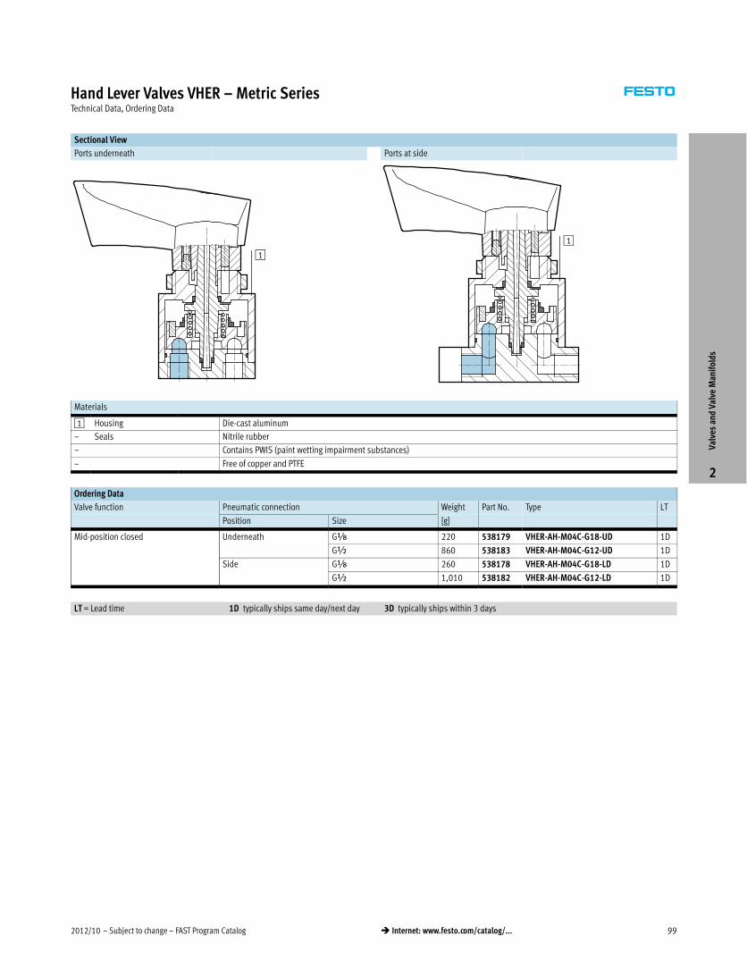
Hand Lever Valves VHER – Metric SeriesTechnical Data, Ordering Data
Sectional View
Ports underneath Ports at side
1
1
Materials
1 Housing Die-cast aluminum
– Seals Nitrile rubber
– Contains PWIS (paint wetting impairment substances)
– Free of copper and PTFE
Ordering Data
Valve function Pneumatic connection Weight Part No. Type LT
Position Size [g]
Mid-position closed Underneath GÁ 220 538179 VHER-AH-M04C-G18-UD 1D
G½ 860 538183 VHER-AH-M04C-G12-UD 1D
Side GÁ 260 538178 VHER-AH-M04C-G18-LD 1D
G½ 1,010 538182 VHER-AH-M04C-G12-LD 1D
LT = Lead time 1D typically ships same day/next day 3D typically ships within 3 days
Valv
es a
nd V
alve
Man
ifol
ds
2
FAST Program Catalog – Subject to change – 2012/10100 � Internet: www.festo.com/catalog/...
Hand Lever Valves VHER – Metric SeriesAccessories
Assembled Valves with Accessories
12
Component parts and accessories Brief description � Page/Internet
1 Hand lever valves VHER Connection size Gx with metal lever 98
2 Hand lever valves VHER Connection size G¼ and G½ with metal lever 98
– Proximity sensors SME-10…1) Not included in scope of delivery 101, sme
Connecting cables Not included in scope of delivery 101
Blanking plugs For use of hand lever valves VHER as 3/3-way valves; plugs not included in scope of delivery 101
Push-in fittings QS Not included in scope of delivery 101, qs
Silencers Not included in scope of delivery 101
1) For valves with pneumatic connection at side, only proximity sensors SME-10… with lateral connection direction are permissible.
Valv
es a
nd V
alve
Man
ifol
ds
2
2012/10 – Subject to change – FAST Program Catalog 101� Internet: www.festo.com/catalog/...
Hand Lever Valves VHER – Metric SeriesAccessories
Ordering data
Switching output Electrical connection Cable
length
[m]
Weight
[g]
Part No. Type
Cable Cable with plug, rotatable
thread
N/O contact
Contacting,
bipolar
2-wire – 2.5 14.6 551369 SME-10M-ZS-24V-E-2,5-L-OE
– M8x1, 3-pin 0.3 6.7 551367 SME-10M-DS-24V-E-0,3-L-M8D
Ordering Data – Connecting Cables Technical Data � www.festo.com/catalog/nebu
Electrical connection, left Electrical connection, right Cable length Part No. Type
[ft]
Straight socket, M8x1, 3-pin Cable, open end, 3-wire 8.2 541333 NEBU-M8G3-K-2.5-LE3
Ordering Data – Blanking Plugs1)
Gx G½
Part No. Type Part No. Type
3568 B-x 3571 B-½
1) Scope of delivery 10 pieces
Ordering Data – Permissible Push-in Fittings QS1)
Gx G½
Part No. Type Part No. Type
Pneumatic connection underneath
153001 QS-x-4 153010 QS-½-12
153002 QS-x-6 153011 QS-½-16
153012 QS-x-4-I
153013 QS-x-6-I
Pneumatic connection at side
153012 QS-x-4-I –
153013 QS-x-6-I
1) Scope of delivery 10 pieces
Ordering Data – Permissible Silencers
Gx G½
Part No. Type Part No. Type
Pneumatic connection underneath
6841 U-x-B 6844 U-½-B
161419 UC-x 2310 U-½
2307 U-x
Pneumatic connection at side
161419 UC-x 6844 U-½-B
Valv
es a
nd V
alve
Man
ifol
ds
2
Lead Time LT for all products on this page: 1D typically ships same day/next day
FAST Program Catalog – Subject to change – 2012/10102 � Internet: www.festo.com/catalog/...
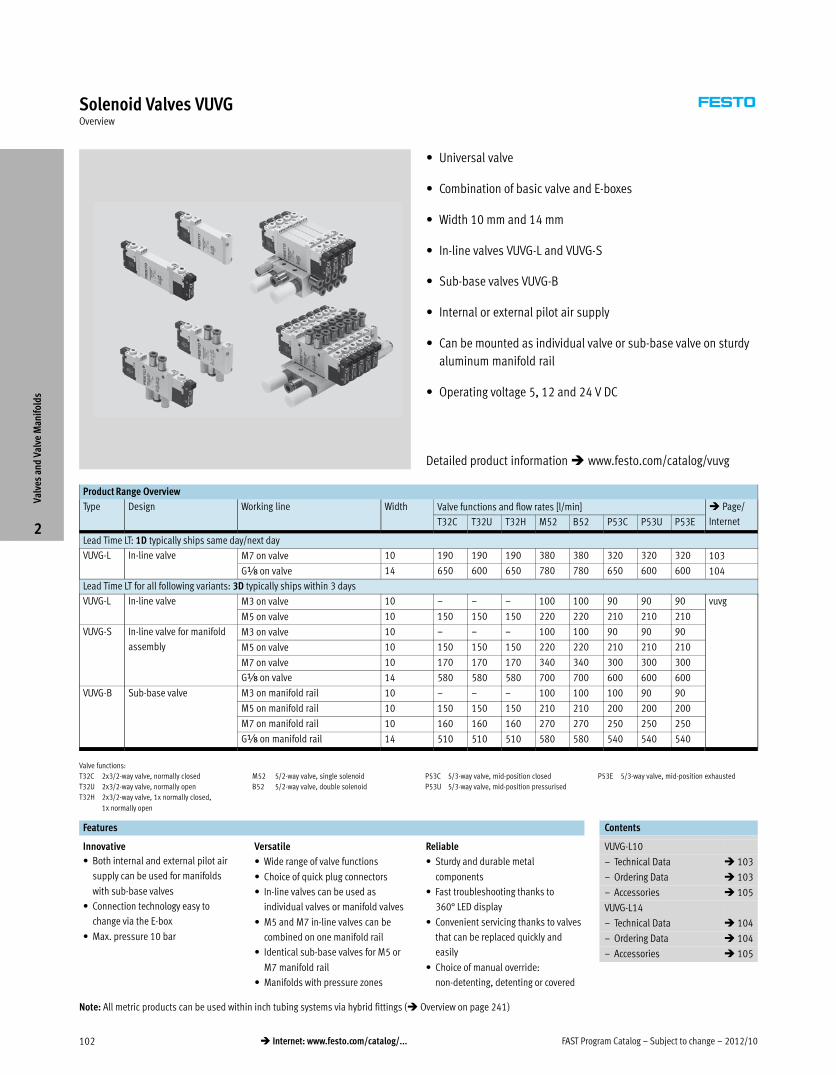
Solenoid Valves VUVGOverview
� Universal valve
� Combination of basic valve and E-boxes
� Width 10 mm and 14 mm
� In-line valves VUVG-L and VUVG-S
� Sub-base valves VUVG-B
� Internal or external pilot air supply
� Can be mounted as individual valve or sub-base valve on sturdy
aluminum manifold rail
� Operating voltage 5, 12 and 24 V DC
Product Range Overview
Type Design Working line Width Valve functions and flow rates [l/min] � Page/
InternetT32C T32U T32H M52 B52 P53C P53U P53E
Lead Time LT: 1D typically ships same day/next day
VUVG-L In-line valve M7 on valve 10 190 190 190 380 380 320 320 320 103
Gx on valve 14 650 600 650 780 780 650 600 600 104
Lead Time LT for all following variants: 3D typically ships within 3 days
VUVG-L In-line valve M3 on valve 10 – – – 100 100 90 90 90 vuvg
M5 on valve 10 150 150 150 220 220 210 210 210
VUVG-S In-line valve for manifold
assembly
M3 on valve 10 – – – 100 100 90 90 90
M5 on valve 10 150 150 150 220 220 210 210 210
M7 on valve 10 170 170 170 340 340 300 300 300
Gx on valve 14 580 580 580 700 700 600 600 600
VUVG-B Sub-base valve M3 on manifold rail 10 – – – 100 100 100 90 90
M5 on manifold rail 10 150 150 150 210 210 200 200 200
M7 on manifold rail 10 160 160 160 270 270 250 250 250
Gx on manifold rail 14 510 510 510 580 580 540 540 540
Valve functions:
T32C 2x3/2-way valve, normally closed
T32U 2x3/2-way valve, normally open
T32H 2x3/2-way valve, 1x normally closed,
1x normally open
M52 5/2-way valve, single solenoid
B52 5/2-way valve, double solenoid
P53C 5/3-way valve, mid-position closed
P53U 5/3-way valve, mid-position pressurised
P53E 5/3-way valve, mid-position exhausted
Features Contents–
Innovative
� Both internal and external pilot air
supply can be used for manifolds
with sub-base valves
� Connection technology easy to
change via the E-box
� Max. pressure 10 bar
Versatile
� Wide range of valve functions
� Choice of quick plug connectors
� In-line valves can be used as
individual valves or manifold valves
� M5 and M7 in-line valves can be
combined on one manifold rail
� Identical sub-base valves for M5 or
M7 manifold rail
� Manifolds with pressure zones
Reliable
� Sturdy and durable metal
components
� Fast troubleshooting thanks to
360° LED display
� Convenient servicing thanks to valves
that can be replaced quickly and
easily
� Choice of manual override:
non-detenting, detenting or covered
VUVG-L10
– Technical Data � 103
– Ordering Data � 103
– Accessories � 105
VUVG-L14
– Technical Data � 104
– Ordering Data � 104
– Accessories � 105–
Valv
es a
nd V
alve
Man
ifol
ds
2
Detailed product information � www.festo.com/catalog/vuvg
Note: All metric products can be used within inch tubing systems via hybrid fittings (� Overview on page 241)
2012/10 – Subject to change – FAST Program Catalog 103� Internet: www.festo.com/catalog/...
Solenoid Valves VUVG-L10, In-line Valves M7Technical Data
General Technical Data Download CAD data � www.festo.com/us/engineering
Valve function 2x3/2-way 5/2-way 5/2-way 5/3-way
single solenoid single solenoid double solenoid single solenoid
Connection: In-line valve 1, 2, 3, 4, 5 M7
12, 14 M3
Connection: Manifold rail 1, 3, 5 GÁ
Vacuum operation at port 1 No Only with external pilot air supply
Design Piston spool valve
Type of mounting Via through-holes1)
Length/width/height [mm] 98/10/33 75/10/33 98/10/33
Electrical connection Via E-box
Operating voltage [V DC] 5, 12 and 24 ±10%
Power [W] 1, reduced to 0.35 with holding current reduction
Switching time on/off / Changeover time [ms] 6/16; – 7/19; – –/–; 7 10/30; 16
Duty cycle [%] 100
Protection class to EN 60529 IP40 (with plug socket), IP65 (with M8)
1) If several valves are to be screwed together via the through-holes to form a block, a minimum gap of 0.3 mm must be ensured by placing spacer discs between them.
Operating and Environmental Conditions
Valve function 2x3/2-way 5/2-way 5/2-way 5/3-way
single solenoid single solenoid double solenoid single solenoid
Operating medium Compressed air to ISO 8573-1:2010 [7:4:4]
Note on operating/pilot medium Operation with lubricated medium possible (in which case lubricated operation will always be required)
Operating pressure at port 1
with pilot air supply
Internal [bar] 1.5 … 8 2.5 … 8 1.5 … 8 3 … 8
External [bar] 1.5 … 10 –0.9 … 10 –0.9 … 10 –0.9 … 10
Operating pressure at port 3 or 5
with pilot air supply
Internal or
external
[bar] –0.9 … 10
Pilot pressure1) [bar] 1.5 … 8 2.5 … 8 1.5 … 8 3 … 8
Ambient temperature [°C] –5 … +50, –5 … +60 with holding current reduction
Temperature of medium [°C] –5 … +50, –5 … +60 with holding current reduction
1) Minimum pilot pressure 50% of operating pressure.
Note on Materials
Housing Wrought aluminum alloy
Seals HNBR, NBR
Ordering Data
Code Valve function Internal pilot air supply LT External pilot air supply LT
Part No. Type Part No. Type
T32C 2x3/2-way valve, normally closed 566471 VUVG-L10-T32C-AT-M7-1P3 1D 566479 VUVG-L10-T32C-AZT-M7-1P3 1D
T32U 2x3/2-way valve, normally open 566472 VUVG-L10-T32U-AT-M7-1P3 1D 566480 VUVG-L10-T32U-AZT-M7-1P3 1D
T32H 2x3/2-way valve, 1x normally closed, 1x normally open 566473 VUVG-L10-T32H-AT-M7-1P3 1D 566481 VUVG-L10-T32H-AZT-M7-1P3 1D
M52 5/2-way valve, single solenoid 566474 VUVG-L10-M52-RT-M7-1P3 1D 566482 VUVG-L10-M52-RZT-M7-1P3 1D
B52 5/2-way valve, double solenoid 566475 VUVG-L10-B52-T-M7-1P3 1D 566483 VUVG-L10-B52-ZT-M7-1P3 1D
P53C 5/3-way valve, mid-position closed 566476 VUVG-L10-P53C-T-M7-1P3 1D 566484 VUVG-L10-P53C-ZT-M7-1P3 1D
P53U 5/3-way valve, mid-position pressurised 566478 VUVG-L10-P53U-T-M7-1P3 1D 566486 VUVG-L10-P53U-ZT-M7-1P3 1D
P53E 5/3-way valve, mid-position exhausted 566477 VUVG-L10-P53E-T-M7-1P3 1D 566485 VUVG-L10-P53E-ZT-M7-1P3 1D
Valve and Valve Terminal Configurator Download CAD Data � www.festo.com/us/cad
A valve terminal configurator is available to help you select further valves VUVG or a suitable
valve terminal VTUG. This makes it much easier to order the right product. Valve terminals type
26 VTUG are ordered via an identcode.
All valve terminals are supplied fully assembled and individually tested. This reduces assembly
and installation time to a minimum
Ordering system for valve VUVG
� Internet: vuvg
Ordering system for valve terminal type 26 VTUG
� Individual electrical connection
� Internet: vtug
Please note: Lead Time LT for configurable variants and options: 3D
LT = Lead time 1D typically ships same day/next day 3D typically ships within 3 days
Valv
es a
nd V
alve
Man
ifol
ds
2
FAST Program Catalog – Subject to change – 2012/10104 � Internet: www.festo.com/catalog/...
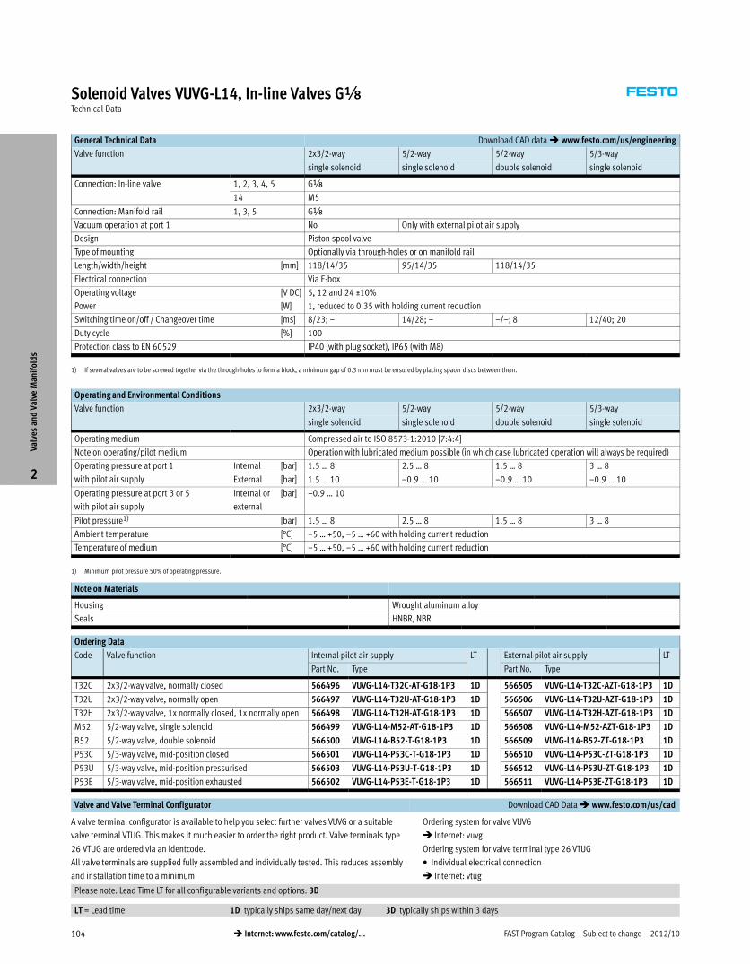
Solenoid Valves VUVG-L14, In-line Valves GxTechnical Data
General Technical Data Download CAD data � www.festo.com/us/engineering
Valve function 2x3/2-way 5/2-way 5/2-way 5/3-way
single solenoid single solenoid double solenoid single solenoid
Connection: In-line valve 1, 2, 3, 4, 5 Gx
14 M5
Connection: Manifold rail 1, 3, 5 GÁ
Vacuum operation at port 1 No Only with external pilot air supply
Design Piston spool valve
Type of mounting Optionally via through-holes or on manifold rail
Length/width/height [mm] 118/14/35 95/14/35 118/14/35
Electrical connection Via E-box
Operating voltage [V DC] 5, 12 and 24 ±10%
Power [W] 1, reduced to 0.35 with holding current reduction
Switching time on/off / Changeover time [ms] 8/23; – 14/28; – –/–; 8 12/40; 20
Duty cycle [%] 100
Protection class to EN 60529 IP40 (with plug socket), IP65 (with M8)
1) If several valves are to be screwed together via the through-holes to form a block, a minimum gap of 0.3 mm must be ensured by placing spacer discs between them.
Operating and Environmental Conditions
Valve function 2x3/2-way 5/2-way 5/2-way 5/3-way
single solenoid single solenoid double solenoid single solenoid
Operating medium Compressed air to ISO 8573-1:2010 [7:4:4]
Note on operating/pilot medium Operation with lubricated medium possible (in which case lubricated operation will always be required)
Operating pressure at port 1
with pilot air supply
Internal [bar] 1.5 … 8 2.5 … 8 1.5 … 8 3 … 8
External [bar] 1.5 … 10 –0.9 … 10 –0.9 … 10 –0.9 … 10
Operating pressure at port 3 or 5
with pilot air supply
Internal or
external
[bar] –0.9 … 10
Pilot pressure1) [bar] 1.5 … 8 2.5 … 8 1.5 … 8 3 … 8
Ambient temperature [°C] –5 … +50, –5 … +60 with holding current reduction
Temperature of medium [°C] –5 … +50, –5 … +60 with holding current reduction
1) Minimum pilot pressure 50% of operating pressure.
Note on Materials
Housing Wrought aluminum alloy
Seals HNBR, NBR
Ordering Data
Code Valve function Internal pilot air supply LT External pilot air supply LT
Part No. Type Part No. Type
T32C 2x3/2-way valve, normally closed 566496 VUVG-L14-T32C-AT-G18-1P3 1D 566505 VUVG-L14-T32C-AZT-G18-1P3 1D
T32U 2x3/2-way valve, normally open 566497 VUVG-L14-T32U-AT-G18-1P3 1D 566506 VUVG-L14-T32U-AZT-G18-1P3 1D
T32H 2x3/2-way valve, 1x normally closed, 1x normally open 566498 VUVG-L14-T32H-AT-G18-1P3 1D 566507 VUVG-L14-T32H-AZT-G18-1P3 1D
M52 5/2-way valve, single solenoid 566499 VUVG-L14-M52-AT-G18-1P3 1D 566508 VUVG-L14-M52-AZT-G18-1P3 1D
B52 5/2-way valve, double solenoid 566500 VUVG-L14-B52-T-G18-1P3 1D 566509 VUVG-L14-B52-ZT-G18-1P3 1D
P53C 5/3-way valve, mid-position closed 566501 VUVG-L14-P53C-T-G18-1P3 1D 566510 VUVG-L14-P53C-ZT-G18-1P3 1D
P53U 5/3-way valve, mid-position pressurised 566503 VUVG-L14-P53U-T-G18-1P3 1D 566512 VUVG-L14-P53U-ZT-G18-1P3 1D
P53E 5/3-way valve, mid-position exhausted 566502 VUVG-L14-P53E-T-G18-1P3 1D 566511 VUVG-L14-P53E-ZT-G18-1P3 1D
Valve and Valve Terminal Configurator Download CAD Data � www.festo.com/us/cad
A valve terminal configurator is available to help you select further valves VUVG or a suitable
valve terminal VTUG. This makes it much easier to order the right product. Valve terminals type
26 VTUG are ordered via an identcode.
All valve terminals are supplied fully assembled and individually tested. This reduces assembly
and installation time to a minimum
Ordering system for valve VUVG
� Internet: vuvg
Ordering system for valve terminal type 26 VTUG
� Individual electrical connection
� Internet: vtug
Please note: Lead Time LT for all configurable variants and options: 3D
LT = Lead time 1D typically ships same day/next day 3D typically ships within 3 days
Valv
es a
nd V
alve
Man
ifol
ds
2
2012/10 – Subject to change – FAST Program Catalog 105� Internet: www.festo.com/catalog/...
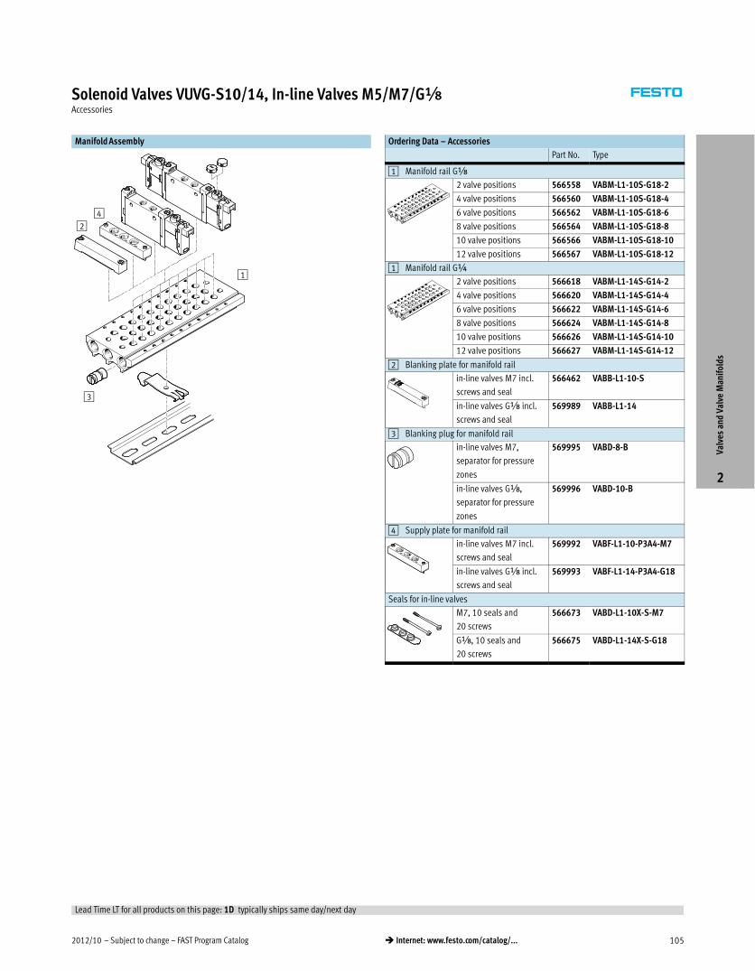
Solenoid Valves VUVG-S10/14, In-line Valves M5/M7/GxAccessories
Manifold Assembly
1
24
3
Ordering Data – Accessories
Part No. Type
1 Manifold rail GÁ
2 valve positions 566558 VABM-L1-10S-G18-2
4 valve positions 566560 VABM-L1-10S-G18-4
6 valve positions 566562 VABM-L1-10S-G18-6
8 valve positions 566564 VABM-L1-10S-G18-8
10 valve positions 566566 VABM-L1-10S-G18-10
12 valve positions 566567 VABM-L1-10S-G18-12
1 Manifold rail G¼
2 valve positions 566618 VABM-L1-14S-G14-2
4 valve positions 566620 VABM-L1-14S-G14-4
6 valve positions 566622 VABM-L1-14S-G14-6
8 valve positions 566624 VABM-L1-14S-G14-8
10 valve positions 566626 VABM-L1-14S-G14-10
12 valve positions 566627 VABM-L1-14S-G14-12
2 Blanking plate for manifold rail
in-line valves M7 incl.
screws and seal
566462 VABB-L1-10-S
in-line valves Gx incl.
screws and seal
569989 VABB-L1-14
3 Blanking plug for manifold rail
in-line valves M7,
separator for pressure
zones
569995 VABD-8-B
in-line valves Gx,
separator for pressure
zones
569996 VABD-10-B
4 Supply plate for manifold rail
in-line valves M7 incl.
screws and seal
569992 VABF-L1-10-P3A4-M7
in-line valves Gx incl.
screws and seal
569993 VABF-L1-14-P3A4-G18
Seals for in-line valves
M7, 10 seals and
20 screws
566673 VABD-L1-10X-S-M7
Gx, 10 seals and
20 screws
566675 VABD-L1-14X-S-G18
Valv
es a
nd V
alve
Man
ifol
ds
2
Lead Time LT for all products on this page: 1D typically ships same day/next day
FAST Program Catalog – Subject to change – 2012/10106 � Internet: www.festo.com/catalog/...
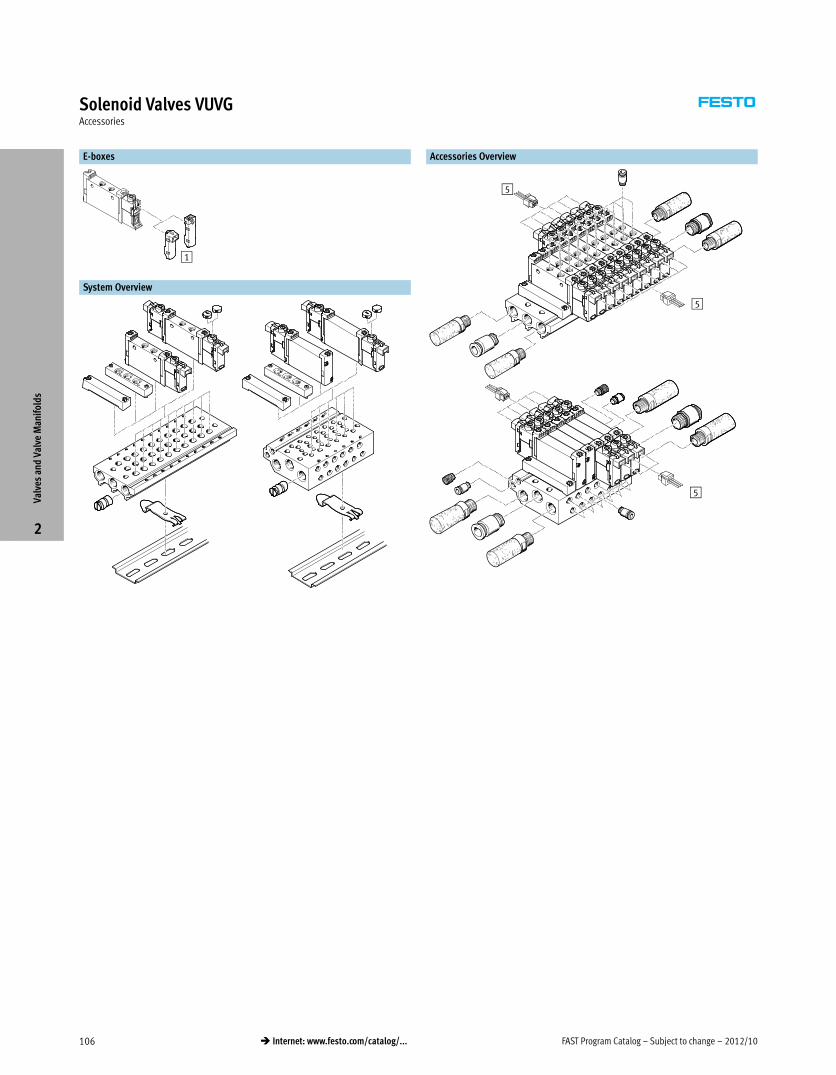
Solenoid Valves VUVGAccessories
E-boxes
1
System Overview
Accessories Overview
5
5
5
Valv
es a
nd V
alve
Man
ifol
ds
2
2012/10 – Subject to change – FAST Program Catalog 107� Internet: www.festo.com/catalog/...
Solenoid Valves VUVGAccessories
Ordering Data
Part No. Type
1 E-boxes,
connection pattern H, horizontal plug
Bipolar 1 W 12/24 V DC 566714 VAVE-L1-1VH2-LP
Holding current reduction 1 W
0.35� W
24 V DC 566716 VAVE-L1-1H2-LR
Connection pattern H, vertical plug
Bipolar 1 W 12/24 V DC 566715 VAVE-L1-1VH3-LP
Holding current reduction 1 W
0.35� W
24 V DC 566717 VAVE-L1-1H3-LR
5 Plug socket with cable, open end
Straight socket, 2-pin,
cable not sheathed
0.5 m 566654 NEBV-H1G2-KN-0.5-LE2
1 m 566655 NEBV-H1G2-KN-1-LE2
2.5 m 566656 NEBV-H1G2-KN-2.5-LE2
5 m 566657 NEBV-H1G2-KN-5-LE2
Straight socket, 2-pin,
cable sheathed
0.5 m 566658 NEBV-H1G2-P-0.5-N-LE2
1 m 566659 NEBV-H1G2-P-1-N-LE2
2.5 m 566660 NEBV-H1G2-P-2.5-N-LE2
5 m 566661 NEBV-H1G2-P-5-N-LE2
Straight socket, M8, 3-pin 2.5 m 541333 NEBU-M8G3-K-2.5-LE3
Inscription label holder
Holder for an inscription label, cover for manual override mounting screw 10 pieces 570818 ASLR-D-L1
Valv
es a
nd V
alve
Man
ifol
ds
2
Lead Time LT for all products on this page: 1D typically ships same day/next day
FAST Program Catalog – Subject to change – 2012/10108 � Internet: www.festo.com/catalog/...
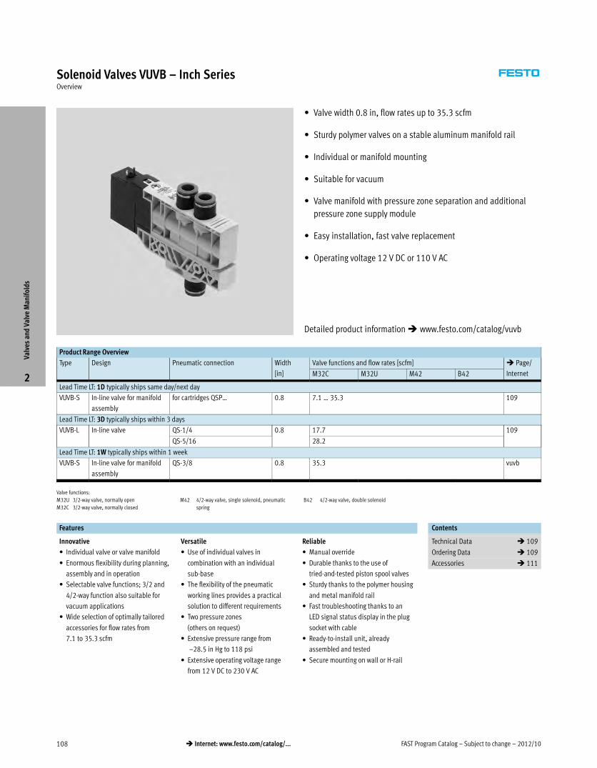
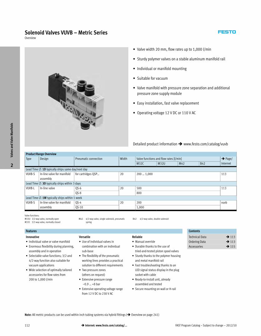
Solenoid Valves VUVB – Inch SeriesOverview
� Valve width 0.8 in, flow rates up to 35.3 scfm
� Sturdy polymer valves on a stable aluminum manifold rail
� Individual or manifold mounting
� Suitable for vacuum
� Valve manifold with pressure zone separation and additional
pressure zone supply module
� Easy installation, fast valve replacement
� Operating voltage 12 V DC or 110 V AC
Product Range Overview
Type Design Pneumatic connection Width
[in]
Valve functions and flow rates [scfm] � Page/
InternetM32C M32U M42 B42
Lead Time LT: 1D typically ships same day/next day
VUVB-S In-line valve for manifold
assembly
for cartridges QSP… 0.8 7.1 … 35.3 109
Lead Time LT: 3D typically ships within 3 days
VUVB-L In-line valve QS-1/4 0.8 17.7 109
QS-5/16 28.2
Lead Time LT: 1W typically ships within 1 week
VUVB-S In-line valve for manifold
assembly
QS-3/8 0.8 35.3 vuvb
Valve functions:
M32U 3/2-way valve, normally open
M32C 3/2-way valve, normally closed
M42 4/2-way valve, single solenoid, pneumatic
spring
B42 4/2-way valve, double solenoid
Features Contents
Innovative
� Individual valve or valve manifold
� Enormous flexibility during planning,
assembly and in operation
� Selectable valve functions; 3/2 and
4/2-way function also suitable for
vacuum applications
� Wide selection of optimally tailored
accessories for flow rates from
7.1 to 35.3 scfm
Versatile
� Use of individual valves in
combination with an individual
sub-base
� The flexibility of the pneumatic
working lines provides a practical
solution to different requirements
� Two pressure zones
(others on request)
� Extensive pressure range from
–28.5 in Hg to 118 psi
� Extensive operating voltage range
from 12 V DC to 230 V AC
Reliable
� Manual override
� Durable thanks to the use of
tried-and-tested piston spool valves
� Sturdy thanks to the polymer housing
and metal manifold rail
� Fast troubleshooting thanks to an
LED signal status display in the plug
socket with cable
� Ready-to-install unit, already
assembled and tested
� Secure mounting on wall or H-rail
Technical Data � 109
Ordering Data � 109
Accessories � 111
Valv
es a
nd V
alve
Man
ifol
ds
2
Detailed product information � www.festo.com/catalog/vuvb
2012/10 – Subject to change – FAST Program Catalog 109� Internet: www.festo.com/catalog/...
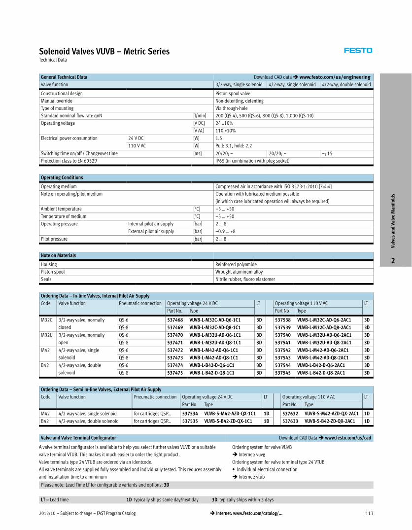
Solenoid Valves VUVB – Inch SeriesTechnical Data
General Technical D!ata Download CAD data � www.festo.com/us/engineering
Valve function 3/2-way, single solenoid 4/2-way, single solenoid 4/2-way, double solenoid
Constructional design Piston spool valve
Manual override Non-detenting, detenting
Type of mounting Via through-hole
Standard nominal flow rate qnN [scfm] 7.1 (QS-3/16), 17.7 (QS-1/4), 28.2 (QS-5/16), 35.3 (QS-3/8)
Operating voltage [V DC] 24 ±10%
[V AC] 110 ±10%
Electrical power consumption 24 V DC [W] 1.5
110 V AC [W] Pull: 3.1, hold: 2.2
Switching time on/off / Changeover time [ms] 20/20; – 20/20; – –; 15
Protection class to EN 60529 IP65 (in combination with plug socket)
Operating Conditions
Operating medium Compressed air in accordance with ISO 85731:2010 [7:4:4]
Note on operating/pilot medium Operation with lubricated medium possible
(in which case lubricated operation will always be required)
Ambient temperature [°F] 23 … 122
Temperature of medium [°F] 23 … 122
Operating pressure Internal pilot air supply [psi] 29.4 … 117.6
External pilot air supply [psi] –28.5 in Hg … 117.6 psi
Pilot pressure [psi] 29.4 … 117.6
Note on Materials
Housing Reinforced polyamide
Piston spool Wrought aluminum alloy
Seals Nitrile rubber, fluoro elastomer
Ordering Data – In-line Valves, Internal Pilot Air Supply
Code Valve function Pneumatic connection Operating voltage 24 V DC LT Operating voltage 110 V AC LT
Part No. Type Part No. Type
M32C 3/2-way valve, normally
closed
QS-1/4 568280 VUVB-L-M32C-AD-T14-1C1 3D 568296 VUVB-L-M32C-AD-T14-2AC1 3D
QS-5/16 568281 VUVB-L-M32C-AD-T516-1C1 3D 568297 VUVB-L-M32C-AD-T516-2AC1 3D
M32U 3/2-way valve, normally
open
QS-1/4 568282 VUVB-L-M32U-AD-T14-1C1 3D 568298 VUVB-L-M32U-AD-T14-2AC1 3D
QS-5/16 568283 VUVB-L-M32U-AD-T516-1C1 3D 568299 VUVB-L-M32U-AD-T516-2AC1 3D
M42 4/2-way valve, single
solenoid
QS-1/4 568284 VUVB-L-M42-AD-T14-1C1 3D 568300 VUVB-L-M42-AD-T14-2AC1 3D
QS-5/16 568285 VUVB-L-M42-AD-T516-1C1 3D 568301 VUVB-L-M42-AD-T516-2AC1 3D
B42 4/2-way valve, double
solenoid
QS-1/4 568286 VUVB-L-B42-D-T14-1C1 3D 568302 VUVB-L-B42-D-T14-2AC1 3D
QS-5/16 568287 VUVB-L-B42-D-T516-1C1 3D 568303 VUVB-L-B42-D-T516-2AC1 3D
Ordering Data – Semi In-line Valves, External Pilot Air Supply
Code Valve function Pneumatic connection Operating voltage 24 V DC LT Operating voltage 110 V AC LT
Part No. Type Part No. Type
M42 4/2-way valve, single solenoid for cartridges QSP... 537534 VUVB-S-M42-AZD-QX-1C1 1D 537632 VUVB-S-M42-AZD-QX-2AC1 1D
B42 4/2-way valve, double solenoid for cartridges QSP... 537535 VUVB-S-B42-ZD-QX-1C1 1D 537633 VUVB-S-B42-ZD-QX-2AC1 1D
Valve and Valve Terminal Configurator Download CAD Data � www.festo.com/us/cad
A valve terminal configurator is available to help you select further valves VUVB or a suitable
valve terminal VTUB. This makes it much easier to order the right product.
Valve terminals type 24 VTUB are ordered via an identcode.
All valve terminals are supplied fully assembled and individually tested. This reduces assembly
and installation time to a minimum
Ordering system for valve VUVB
� Internet: vuvb
Ordering system for valve terminal type 24 VTUB
� Individual electrical connection
� Internet: vtub
Please note: Lead Time LT for configurable variants and options: 3D
LT = Lead time 1D typically ships same day/next day 3D typically ships within 3 days
Valv
es a
nd V
alve
Man
ifol
ds
2
FAST Program Catalog – Subject to change – 2012/10110 � Internet: www.festo.com/catalog/...
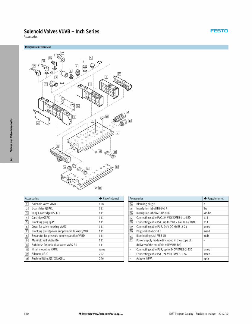
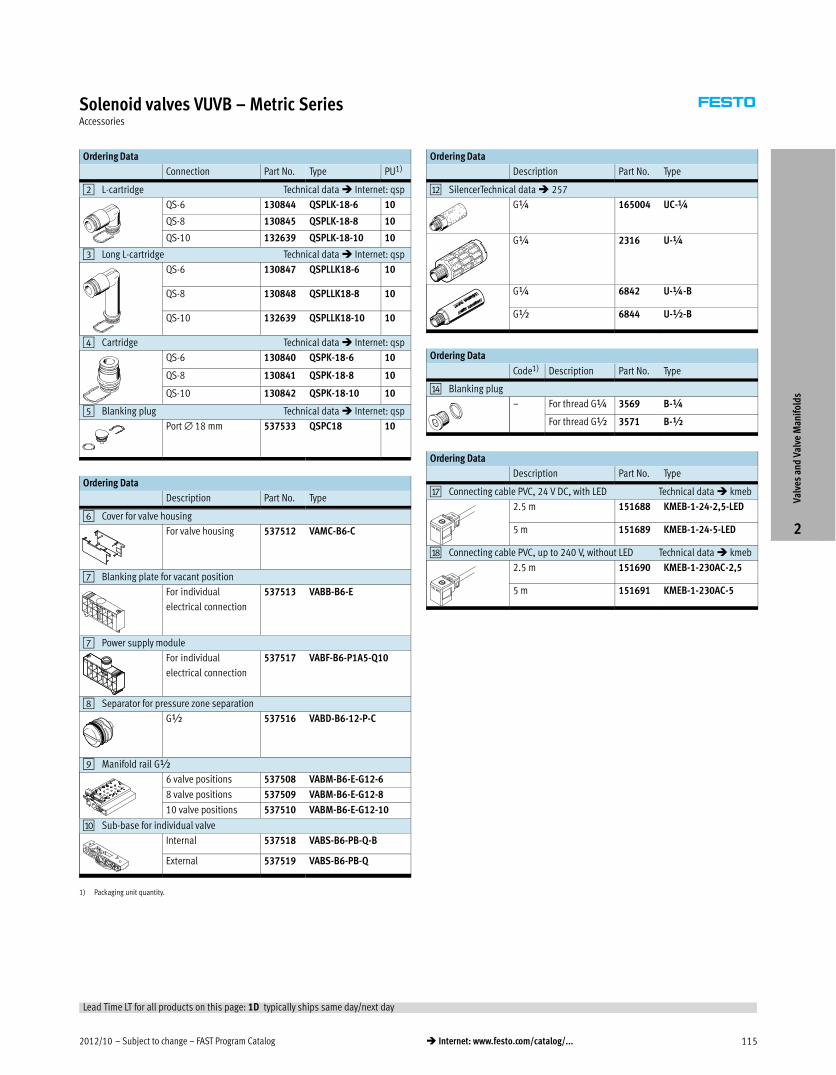
Solenoid Valves VUVB – Inch SeriesAccessories
Peripherals Overview
aG
aH
aI
bJ
bA
2
1
1
7bB
aJ
8
aE
aB
aC
aF
9
aD aA
3
4
aJ
6
6
aA
aF
4
45
Accessories � Page/Internet
1 Solenoid valve VUVB 108
2 L-cartridge QSPKL 111
3 Long L-cartridge QSPKLL 111
4 Cartridge QSPK 111
5 Blanking plug QSPC 111
6 Cover for valve housing VAMC 111
7 Blanking plate/power supply module VABB/VABF 111
8 Separator for pressure zone separation VABD 111
9 Manifold rail VABM-B6 111
aJ Sub-base for individual valve VABS-B6 111
aA H-rail mounting VAME vame
aB Silencer U/UC 257
aC Push-in fitting QS/QSL/QSLL 246
Accessories � Page/Internet
aD Blanking plug B b
aE Inscription label IBS-9x17 ibs
aF Inscription label MH-BZ-80X Mh-bz
aG Connecting cable PVC, 24 V DC KMEB-1-…-LED 111
aH Connecting cable PVC, up to 240 V KMEB-1-230AC 111
aI Connecting cable PUR, 24 V DC KMEB-2-24 kmeb
bJ Plug socket MSSD-EB mssd
bA Illuminating seal MEB-LD meb
bB Power supply module (included in the scope of
delivery of the manifold rail VABM-B6)
–
– Connecting cable PUR, up to 240V KMEB-2-230 kmeb
– Connecting cable PVC, 24 V DC KMEB-3-24 kmeb
– Adapter NPFA npfa
Valv
es a
nd V
alve
Man
ifol
ds
2
2012/10 – Subject to change – FAST Program Catalog 111� Internet: www.festo.com/catalog/...
Solenoid Valves VUVB – Inch SeriesAccessories
Ordering Data
Connection Part No. Type PU1)
2 L-cartridge Technical data � Internet: qsp
QS-1/4 132176 QSPLK18-1/4-U 10
QS-5/16 132177 QSPLK18-5/16-U 10
QS-3/8 132641 QSPK18-3/8-U 10
3 Long L-cartridge Technical data � Internet: qsp
QS-1/4 132179 QSPLLK18-1/4-U 10
QS-5/16 132180 QSPLLK18-5/16-U 10
QS-3/8 132642 QSPLLK18-3/8-U 10
4 Cartridge Technical data � Internet: qsp
QS-1/4 132172 QSPK18-1/4-U 10
QS-5/16 132173 QSPK18-5/16-U 10
QS-3/8 132174 QSPK18-3/8-U 10
5 Blanking plug Technical data � Internet: qsp
Port ∅ 18 mm 537533 QSPC18 10
Ordering Data
Description Part No. Type
6 Cover for valve housing
For valve housing 537512 VAMC-B6-C
7 Blanking plate for vacant position
For individual
electrical
connection
537513 VABB-B6-E
7 Power supply module
For individual
electrical
connection
568624 VABF-B6-P1A5-T38
8 Separator for pressure zone separation
G½ 537516 VABD-B6-12-P-C
9 Manifold rail ½ NPT
6 valve positions 570727 VABM-B6-E-N12-6
8 valve positions 570728 VABM-B6-E-N12-8
10 valve positions 570729 VABM-B6-E-N12-10
aJ Sub-base for individual valve
Internal 537518 VABS-B6-PB-Q-B
External 537519 VABS-B6-PB-Q
1) Packaging unit quantity.
Ordering Data
Description Part No. Type
aB Silencer Technical data � 257
¼NPT 12639 U-¼-B-NPT
yNPT 12740 U-y-B-NPT
½NPT 12741 U-½-B-NPT
Ordering Data
Description Part No. Type
aG Connecting cable PVC, 24 V DC, with LED Technical data � kmeb
2.5 m 151688 KMEB-1-24-2,5-LED
5 m 151689 KMEB-1-24-5-LED
aH Connecting cable PVC, up to 240 V, without LED Technical data � kmeb
2.5 m 151690 KMEB-1-230AC-2,5
5 m 151691 KMEB-1-230AC-5
Valv
es a
nd V
alve
Man
ifol
ds
2
Lead Time LT for all products on this page: 1D typically ships same day/next day
FAST Program Catalog – Subject to change – 2012/10112 � Internet: www.festo.com/catalog/...
Solenoid Valves VUVB – Metric SeriesOverview
� Valve width 20 mm, flow rates up to 1,000 l/min
� Sturdy polymer valves on a stable aluminum manifold rail
� Individual or manifold mounting
� Suitable for vacuum
� Valve manifold with pressure zone separation and additional
pressure zone supply module
� Easy installation, fast valve replacement
� Operating voltage 12 V DC or 110 V AC
Product Range Overview
Type Design Pneumatic connection Width Valve functions and flow rates [l/min] � Page/
InternetM32C M32U M42 B42
Lead Time LT: 1D typically ships same day/next day
VUVB-S In-line valve for manifold
assembly
for cartridges QSP… 20 200 … 1,000 113
Lead Time LT: 3D typically ships within 3 days
VUVB-L In-line valve QS-6 20 500 113
QS-8 800
Lead Time LT: 1W typically ships within 1 week
VUVB-S In-line valve for manifold
assembly
QS-4 20 200 vuvb
QS-10 1,000
Valve functions:
M32U 3/2-way valve, normally open
M32C 3/2-way valve, normally closed
M42 4/2-way valve, single solenoid, pneumatic
spring
B42 4/2-way valve, double solenoid
Features Contents
Innovative
� Individual valve or valve manifold
� Enormous flexibility during planning,
assembly and in operation
� Selectable valve functions; 3/2 and
4/2-way function also suitable for
vacuum applications
� Wide selection of optimally tailored
accessories for flow rates from
200 to 1,000 l/min
Versatile
� Use of individual valves in
combination with an individual
sub-base
� The flexibility of the pneumatic
working lines provides a practical
solution to different requirements
� Two pressure zones
(others on request)
� Extensive pressure range
–0.9 … +8 bar
� Extensive operating voltage range
from 12 V DC to 230 V AC
Reliable
� Manual override
� Durable thanks to the use of
tried-and-tested piston spool valves
� Sturdy thanks to the polymer housing
and metal manifold rail
� Fast troubleshooting thanks to an
LED signal status display in the plug
socket with cable
� Ready-to-install unit, already
assembled and tested
� Secure mounting on wall or H-rail
Technical Data � 113
Ordering Data � 113
Accessories � 115
Valv
es a
nd V
alve
Man
ifol
ds
2
Detailed product information � www.festo.com/catalog/vuvb
Note: All metric products can be used within inch tubing systems via hybrid fittings (� Overview on page 241)
2012/10 – Subject to change – FAST Program Catalog 113� Internet: www.festo.com/catalog/...
Solenoid Valves VUVB – Metric SeriesTechnical Data
General Technical D!ata Download CAD data � www.festo.com/us/engineering
Valve function 3/2-way, single solenoid 4/2-way, single solenoid 4/2-way, double solenoid
Constructional design Piston spool valve
Manual override Non-detenting, detenting
Type of mounting Via through-hole
Standard nominal flow rate qnN [l/min] 200 (QS-4), 500 (QS-6), 800 (QS-8), 1,000 (QS-10)
Operating voltage [V DC] 24 ±10%
[V AC] 110 ±10%
Electrical power consumption 24 V DC [W] 1.5
110 V AC [W] Pull: 3.1, hold: 2.2
Switching time on/off / Changeover time [ms] 20/20; – 20/20; – –; 15
Protection class to EN 60529 IP65 (in combination with plug socket)
Operating Conditions
Operating medium Compressed air in accordance with ISO 85731:2010 [7:4:4]
Note on operating/pilot medium Operation with lubricated medium possible
(in which case lubricated operation will always be required)
Ambient temperature [°C] –5 … +50
Temperature of medium [°C] –5 … +50
Operating pressure Internal pilot air supply [bar] 2 … 8
External pilot air supply [bar] –0.9 … +8
Pilot pressure [bar] 2 … 8
Note on Materials
Housing Reinforced polyamide
Piston spool Wrought aluminum alloy
Seals Nitrile rubber, fluoro elastomer
Ordering Data – In-line Valves, Internal Pilot Air Supply
Code Valve function Pneumatic connection Operating voltage 24 V DC LT Operating voltage 110 V AC LT
Part No. Type Part No Type
M32C 3/2-way valve, normally
closed
QS-6 537468 VUVB-L-M32C-AD-Q6-1C1 3D 537538 VUVB-L-M32C-AD-Q6-2AC1 3D
QS-8 537469 VUVB-L-M32C-AD-Q8-1C1 3D 537539 VUVB-L-M32C-AD-Q8-2AC1 3D
M32U 3/2-way valve, normally
open
QS-6 537470 VUVB-L-M32U-AD-Q6-1C1 3D 537540 VUVB-L-M32U-AD-Q6-2AC1 3D
QS-8 537471 VUVB-L-M32U-AD-Q8-1C1 3D 537541 VUVB-L-M32U-AD-Q8-2AC1 3D
M42 4/2-way valve, single
solenoid
QS-6 537472 VUVB-L-M42-AD-Q6-1C1 3D 537542 VUVB-L-M42-AD-Q6-2AC1 3D
QS-8 537473 VUVB-L-M42-AD-Q8-1C1 3D 537543 VUVB-L-M42-AD-Q8-2AC1 3D
B42 4/2-way valve, double
solenoid
QS-6 537474 VUVB-L-B42-D-Q6-1C1 3D 537544 VUVB-L-B42-D-Q6-2AC1 3D
QS-8 537475 VUVB-L-B42-D-Q8-1C1 3D 537545 VUVB-L-B42-D-Q8-2AC1 3D
Ordering Data – Semi In-line Valves, External Pilot Air Supply
Code Valve function Pneumatic connection Operating voltage 24 V DC LT Operating voltage 110 V AC LT
Part No. Type Part No. Type
M42 4/2-way valve, single solenoid for cartridges QSP... 537534 VUVB-S-M42-AZD-QX-1C1 1D 537632 VUVB-S-M42-AZD-QX-2AC1 1D
B42 4/2-way valve, double solenoid for cartridges QSP... 537535 VUVB-S-B42-ZD-QX-1C1 1D 537633 VUVB-S-B42-ZD-QX-2AC1 1D
Valve and Valve Terminal Configurator Download CAD Data � www.festo.com/us/cad
A valve terminal configurator is available to help you select further valves VUVB or a suitable
valve terminal VTUB. This makes it much easier to order the right product.
Valve terminals type 24 VTUB are ordered via an identcode.
All valve terminals are supplied fully assembled and individually tested. This reduces assembly
and installation time to a minimum
Ordering system for valve VUVB
� Internet: vuvg
Ordering system for valve terminal type 24 VTUB
� Individual electrical connection
� Internet: vtub
Please note: Lead Time LT for configurable variants and options: 3D
LT = Lead time 1D typically ships same day/next day 3D typically ships within 3 days
Valv
es a
nd V
alve
Man
ifol
ds
2

FAST Program Catalog – Subject to change – 2012/10114 � Internet: www.festo.com/catalog/...
Solenoid Valves VUVB – Metric SeriesAccessories
Peripherals Overview
aG
aH
aI
bJ
bA
2
1
1
7bB
aJ
8
aE
aB
aC
aF
9
aD aA
3
4
aJ
6
6
aA
aF
4
45
Accessories � Page/Internet
1 Solenoid valve VUVB 112
2 L-cartridge QSPKL 115
3 Long L-cartridge QSPKLL 115
4 Cartridge QSPK 115
5 Blanking plug QSPC 115
6 Cover for valve housing VAMC 115
7 Blanking plate/power supply module VABB/VABF 115
8 Separator for pressure zone separation VABD 115
9 Manifold rail VABM-B6 115
aJ Sub-base for individual valve VABS-B6 115
aA H-rail mounting VAME vame
aB Silencer U/UC 257
aC Push-in fitting QS/QSL/QSLL 246
Accessories � Page/Internet
aD Blanking plug B 115
aE Inscription label IBS-9x17 ibs
aF Inscription label MH-BZ-80X Mh-bz
aG Connecting cable PVC, 24 V DC KMEB-1-…-LED 115
aH Connecting cable PVC, up to 240 V KMEB-1-230AC 115
aI Connecting cable PUR, 24 V DC KMEB-2-24 kmeb
bJ Plug socket MSSD-EB mssd
bA Illuminating seal MEB-LD meb
bB Power supply module (included in the scope of
delivery of the manifold rail VABM-B6)
–
– Connecting cable PUR, up to 240V KMEB-2-230 kmeb
– Connecting cable PVC, 24 V DC KMEB-3-24 kmeb
– Adapter NPFA npfa
Valv
es a
nd V
alve
Man
ifol
ds
2
2012/10 – Subject to change – FAST Program Catalog 115� Internet: www.festo.com/catalog/...
Solenoid valves VUVB – Metric SeriesAccessories
Ordering Data
Connection Part No. Type PU1)
2 L-cartridge Technical data � Internet: qsp
QS-6 130844 QSPLK-18-6 10
QS-8 130845 QSPLK-18-8 10
QS-10 132639 QSPLK-18-10 10
3 Long L-cartridge Technical data � Internet: qsp
QS-6 130847 QSPLLK18-6 10
QS-8 130848 QSPLLK18-8 10
QS-10 132639 QSPLLK18-10 10
4 Cartridge Technical data � Internet: qsp
QS-6 130840 QSPK-18-6 10
QS-8 130841 QSPK-18-8 10
QS-10 130842 QSPK-18-10 10
5 Blanking plug Technical data � Internet: qsp
Port ∅ 18 mm 537533 QSPC18 10
Ordering Data
Description Part No. Type
6 Cover for valve housing
For valve housing 537512 VAMC-B6-C
7 Blanking plate for vacant position
For individual
electrical connection
537513 VABB-B6-E
7 Power supply module
For individual
electrical connection
537517 VABF-B6-P1A5-Q10
8 Separator for pressure zone separation
G½ 537516 VABD-B6-12-P-C
9 Manifold rail G½
6 valve positions 537508 VABM-B6-E-G12-6
8 valve positions 537509 VABM-B6-E-G12-8
10 valve positions 537510 VABM-B6-E-G12-10
aJ Sub-base for individual valve
Internal 537518 VABS-B6-PB-Q-B
External 537519 VABS-B6-PB-Q
1) Packaging unit quantity.
Ordering Data
Description Part No. Type
aB SilencerTechnical data � 257
G¼ 165004 UC-¼
G¼ 2316 U-¼
G¼ 6842 U-¼-B
G½ 6844 U-½-B
Ordering Data
Code1) Description Part No. Type
aD Blanking plug
– For thread G¼ 3569 B-¼
For thread G½ 3571 B-½
Ordering Data
Description Part No. Type
aG Connecting cable PVC, 24 V DC, with LED Technical data � kmeb
2.5 m 151688 KMEB-1-24-2,5-LED
5 m 151689 KMEB-1-24-5-LED
aH Connecting cable PVC, up to 240 V, without LED Technical data � kmeb
2.5 m 151690 KMEB-1-230AC-2,5
5 m 151691 KMEB-1-230AC-5
Valv
es a
nd V
alve
Man
ifol
ds
2
Lead Time LT for all products on this page: 1D typically ships same day/next day
FAST Program Catalog – Subject to change – 2012/10116 � Internet: www.festo.com/catalog/...
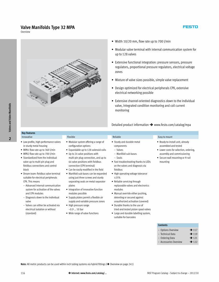
Valve Manifolds Type 32 MPAOverview
� Width 10/20 mm, flow rate up to 700 l/min
� Modular valve terminal with internal communication system for
up to 128 valves
� Extensive functional integration: pressure sensors, pressure
regulators, proportional pressure regulators, electrical voltage
zones
� Mixture of valve sizes possible, simple valve replacement
� Design optimized for electrical peripherals CPX, extensive
electrical networking possible
� Extensive channel-oriented diagnostics down to the individual
valve, integrated condition monitoring and coil current
monitoring
Key Features
Innovative Flexible Reliable Easy to mount
� Low-profile, high-performance valves
in sturdy metal housing
� MPA1 flow rate up to 360 l/min
� MPA2 flow rate up to 700 l/min
� Standardized from the individual
valve up to multi-pin plug and
fieldbus connections and control
block
� Dream team: fieldbus valve terminal
suitable for electrical peripherals
CPX. This means
– Advanced internal communication
system for activation of the valves
and CPX modules
– Diagnosis down to the individual
valve
– Valves can either be activated via
electrical isolation or without
(standard)
� Modular system offering a range of
configuration options
� Expandable up to 128 solenoid coils
� Up to 24 valve positions with
multi-pin plug connection, and up to
64 valve positions with fieldbus
connection (CPX terminal)
� Can be easily modified in the field
� Manifold sub-bases can be expanded
using just three screws and sturdy
separating seals on metal separator
plates
� Integration of innovative function
modules possible
� Supply plates permit a flexible air
supply and variable pressure zones
� High pressure range
–0.9 … 10 bar
� Wide range of valve functions
� Sturdy and durable metal
components
– Valves
– Manifold sub-bases
– Seals
� Fast troubleshooting thanks to LEDs
on the valves and diagnosis via
fieldbus
� High operating voltage tolerance
±25%
� Reliable servicing through
replaceable valves and electronics
modules
� Manual override either pushing,
detenting or secured against
unauthorized activation (covered)
� Durable thanks to the use of
tried-and-tested piston spool valves
� Large and durable labelling system,
suitable for barcodes
� Ready-to-install unit, already
assembled and tested
� Lower costs for selection, ordering,
assembly and commissioning
� Secure wall mounting or H-rail
mounting
Contents
– Options Overview � 117
– Technical Data � 119
– Ordering Data � 121
– Accessories Overview � 122
Valv
es a
nd V
alve
Man
ifol
ds
2
Detailed product information � www.festo.com/catalog/mpa
Note: All metric products can be used within inch tubing systems via hybrid fittings (� Overview on page 241)
2012/10 – Subject to change – FAST Program Catalog 117� Internet: www.festo.com/catalog/...
Valve Manifolds Type 32 MPAOverview
Valve Types
M 5/2-way valve, single solenoid
J 5/2-way valve, double solenoid
N 2x 3/2-way valve, normally open
K 2x 3/2-way valve, normally closed
H 2x 3/2-way valve,
– 1x normally open,
– 1x normally closed
B 5/3-way valve,
mid-position pressurized
G 5/3-way valve, mid-position closed
E 5/3-way valve,
mid-position exhausted
D 2x 2/2-way valve, normally closed
I 2x 2/2-way valve,
– 1x normally closed,
– 1x normally closed, reversible
X 1x 3/2-way valve, normally closed,
external compressed air supply
W 1x 3/2-way valve, normally open,
external compressed air supply
P Manual pressure regulators
Q Proportional pressure regulators
PG External pressure sensor
L Blanking plate for vacant valve
position
A, B, H Electronics module for fieldbus
with extended diagnostic function
Electrical Connection Options
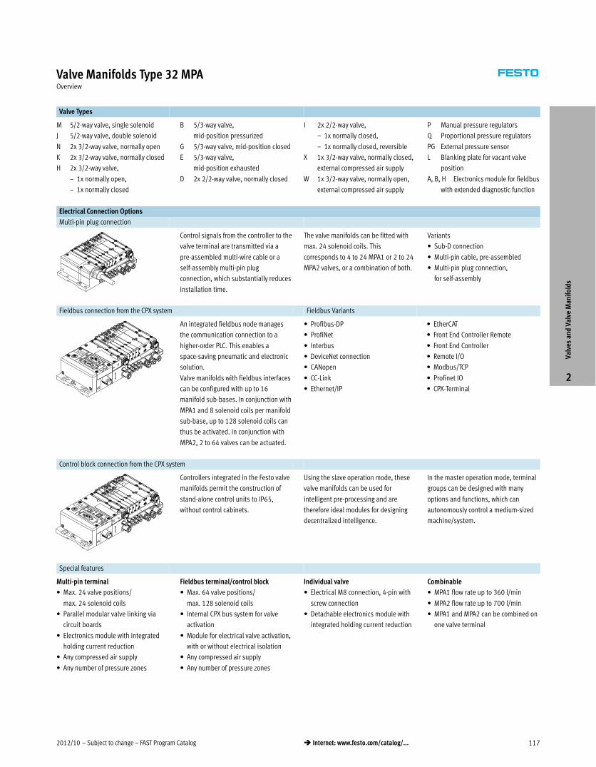
Multi-pin plug connection
Control signals from the controller to the
valve terminal are transmitted via a
pre-assembled multi-wire cable or a
self-assembly multi-pin plug
connection, which substantially reduces
installation time.
The valve manifolds can be fitted with
max. 24 solenoid coils. This
corresponds to 4 to 24 MPA1 or 2 to 24
MPA2 valves, or a combination of both.
Variants
� Sub-D connection
� Multi-pin cable, pre-assembled
� Multi-pin plug connection,
for self-assembly
Fieldbus connection from the CPX system Fieldbus Variants
An integrated fieldbus node manages
the communication connection to a
higher-order PLC. This enables a
space-saving pneumatic and electronic
solution.
Valve manifolds with fieldbus interfaces
can be configured with up to 16
manifold sub-bases. In conjunction with
MPA1 and 8 solenoid coils per manifold
sub-base, up to 128 solenoid coils can
thus be activated. In conjunction with
MPA2, 2 to 64 valves can be actuated.
� Profibus-DP
� ProfiNet
� Interbus
� DeviceNet connection
� CANopen
� CC-Link
� Ethernet/IP
� EtherCAT
� Front End Controller Remote
� Front End Controller
� Remote I/O
� Modbus/TCP
� Profinet IO
� CPX-Terminal
Control block connection from the CPX system
Controllers integrated in the Festo valve
manifolds permit the construction of
stand-alone control units to IP65,
without control cabinets.
Using the slave operation mode, these
valve manifolds can be used for
intelligent pre-processing and are
therefore ideal modules for designing
decentralized intelligence.
In the master operation mode, terminal
groups can be designed with many
options and functions, which can
autonomously control a medium-sized
machine/system.
Special features
Multi-pin terminal
� Max. 24 valve positions/
max. 24 solenoid coils
� Parallel modular valve linking via
circuit boards
� Electronics module with integrated
holding current reduction
� Any compressed air supply
� Any number of pressure zones
Fieldbus terminal/control block
� Max. 64 valve positions/
max. 128 solenoid coils
� Internal CPX bus system for valve
activation
� Module for electrical valve activation,
with or without electrical isolation
� Any compressed air supply
� Any number of pressure zones
Individual valve
� Electrical M8 connection, 4-pin with
screw connection
� Detachable electronics module with
integrated holding current reduction
Combinable
� MPA1 flow rate up to 360 l/min
� MPA2 flow rate up to 700 l/min
� MPA1 and MPA2 can be combined on
one valve terminal
Valv
es a
nd V
alve
Man
ifol
ds
2
FAST Program Catalog – Subject to change – 2012/10118 � Internet: www.festo.com/catalog/...
Valve Manifolds Type 32 MPAOverview
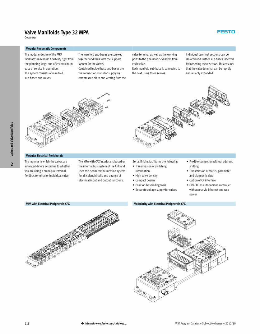
Modular Pneumatic Components
The modular design of the MPA
facilitates maximum flexibility right from
the planning stage and offers maximum
ease of service in operation.
The system consists of manifold
sub-bases and valves.
The manifold sub-bases are screwed
together and thus form the support
system for the valves.
Contained inside these sub-bases are
the connection ducts for supplying
compressed air to and venting from the
valve terminal as well as the working
ports to the pneumatic cylinders from
each valve.
Each manifold sub-base is connected to
the next using three screws.
Individual terminal sections can be
isolated and further sub-bases inserted
by loosening these screws. This ensures
that the valve terminal can be rapidly
and reliably expanded.
Modular Electrical Peripherals
The manner in which the valves are
activated differs according to whether
you are using a multi-pin terminal,
fieldbus terminal or individual valve.
The MPA with CPX interface is based on
the internal bus system of the CPX and
uses this serial communication system
for all solenoid coils and a range of
electrical input and output functions.
Serial linking facilitates the following:
� Transmission of switching
information
� High valve density
� Compact design
� Position-based diagnosis
� Separate voltage supply for valves
� Flexible conversion without address
shifting
� Transmission of status, parameter
and diagnostic data
� Option of CP interface
� CPX-FEC as autonomous controller
with access via Ethernet and web
server
MPA with Electrical Peripherals CPX Modularity with Electrical Peripherals CPX
Valv
es a
nd V
alve
Man
ifol
ds
2
2012/10 – Subject to change – FAST Program Catalog 119� Internet: www.festo.com/catalog/...
Valve Manifolds Type 32 MPATechnical Data
Valve Terminal with Multi-pin Plug or Fieldbus Connection
Flow rate:
� MPA1: up to 360 l/min
� MPA2: up to 700 l/min
Valve width:
� MPA1: 10 mm
� MPA2: 20 mm
Voltage:
� 24 V DC
Materials
Connection block, valve, supply plate,
right-hand end plate, left-hand
pneumatic interface:
Die-cast aluminum
Seals: NBR, elastomer
Exhaust plate: Polyamide
Flat plate silencer: Polyethylene
Electronics module: Polycarbonate
Electrical manifold module:
Bronze/polybutylene terephthalate
General Technical Data
MPA1 MPA2
Constructional design Electromagnetically actuated piston spool valve
Nominal size [mm] 2.5
Lubrication Lubrication for life, PWIS-free (free of paint-wetting impairment substances)
Type of mounting Wall mounting
On H-rail to EN 60715
Standard nominal flow rate [l/min] Max. 360 Max. 700
Manual override Non-detenting, rotary/detenting, covered
Pneumatic connections
Pneumatic connection Via manifold sub-base
Supply port 1 G¼
Exhaust port 3/5 QS-10
Working ports 2/4 Depending on the connection type selected
M7 Gx
QS4 QS6
QS6 QS8
Pilot air supply port 12/14 M7
Pilot exhaust air port 82/84 M7
Pressure relieving port With ducted exhaust air: via port 82/84 (M5 with individual sub-base)
With flat plate silencer: venting to atmosphere
Valve Switching Times [ms]
Valve function order code M J N K H B G E X W D I KS DS
MPA1
Switching times on 10 10 10 10 10 10 10 10 10 10 10 10 14 14
off 20 – 20 20 20 35 35 35 20 20 20 20 16 16
changeover – 15 – – – – – – – – – – – –
MPA2
Switching times on 15 9 8 8 8 11 10 11 13 13 7 7 – –
off 28 – 28 28 28 46 40 47 22 22 25 25 – –
changeover – 22 – – – 23 21 23 – – – – – –
Valv
es a
nd V
alve
Man
ifol
ds
2
FAST Program Catalog – Subject to change – 2012/10120 � Internet: www.festo.com/catalog/...
Valve Manifolds Type 32 MPATechnical Data
Operating and Environmental Conditions
Valve function order code M J N K H B G E X W D I KS DS
Operating medium Compressed air in accordance with ISO 8573-1:2010 [7:4:4]
Note on operating/pilot medium Operation with lubricated medium possible (in which case lubricated operation will always be
required)
Grade of filtration [μm] 40
Operating pressure [bar] –0.9 … +10 3 … 10 –0.9 … +10 3 … 10 –0.9 … +8
Operating pressure for valve terminal with
internal pilot air supply
[bar] 3 … 8
Pilot pressure [bar] 3 … 8
Ambient temperature [°C] –5 … +50
Temperature of medium [°C] –5 … +50
Storage temperature1) [°C] –20 … +40
Relative air humidity at 40 °C [%] 90
1) Long-term storage
Electrical Data – MPA with CPX Terminal
Voltage supply for electronics (UEL/SEN)
Nominal voltage [V] 24 DC
Operating voltage range [V] 18 … 30 DC
Steady state current consumption at 24 V DC [mA] 20
Load voltage supply for valves (Uval)
Nominal voltage [V] 24 DC
Operating voltage range [V] 18 … 30 DC
Max. intrinsic current consumption at 24 V
(regardless of the switching status of the valves)
per electronics module
VMPA1-FB-EMS-8 or VMPA2-FB-EMS-4
VMPA1-FB-EMG-8 or VMPA2-FB-EMG-4
[mA]
[mA]
8 not electrically isolated (max. signal line length 10 m)
25 electrically isolated
Diagnostic message on undervoltage UOFF Load voltage outside
function range
[V] 17.5 … 16
Protection class to EN 60529 IP65 (for all types of signal transmission in assembled state)
Max. current consumption per solenoid coil at nominal voltage MPA1 MPA2
Nominal pull current/duration [mA] 45/20 ms 90/20 ms
Nominal current with current reduction [mA] 8 after 20 ms 18 after 20 ms
Calculation example
Current consumption with two solenoid coils MPA2 switched in
parallel and one electronics module without electrical isolation
[mA] IEl/SEN = 20
Nominal pull current [mA] IVAL = 8 + 2 x 90 = 188
Nominal current with current reduction [mA] IVAL = 8 + 2 x 18 = 44
Electrical Data – MPA with Multi-pin Plug Connection
Nominal voltage [V] 24 DC
Operating voltage range [V] 18 … 30 DC
Residual ripple 4 Vss
Current consumption at Sub-D multi-pin plug connection
per solenoid coil at nominal voltage
MPA1 MPA2
Nominal pull current/duration [mA] 80/25 ms 100/50 ms
Nominal current with current reduction [mA] 25 after 25 ms 20 after 50 ms
Valv
es a
nd V
alve
Man
ifol
ds
2
2012/10 – Subject to change – FAST Program Catalog 121� Internet: www.festo.com/catalog/...
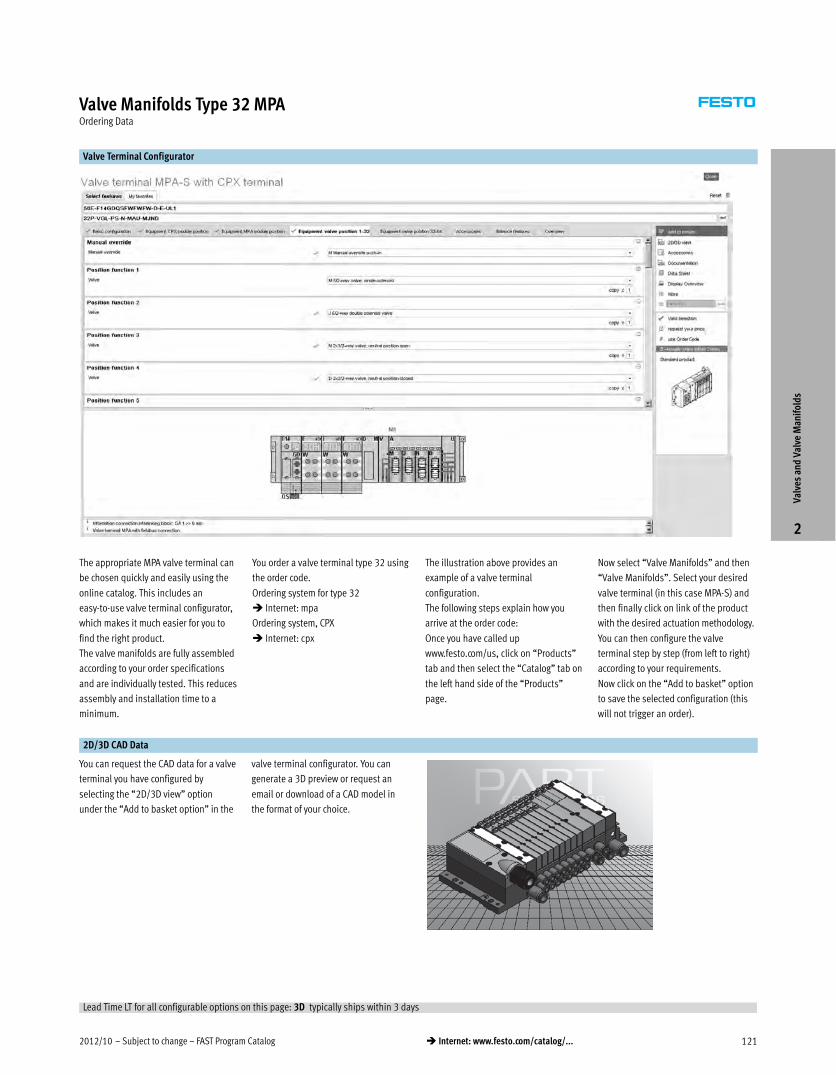
Valve Manifolds Type 32 MPAOrdering Data
Valve Terminal Configurator
The appropriate MPA valve terminal can
be chosen quickly and easily using the
online catalog. This includes an
easy-to-use valve terminal configurator,
which makes it much easier for you to
find the right product.
The valve manifolds are fully assembled
according to your order specifications
and are individually tested. This reduces
assembly and installation time to a
minimum.
You order a valve terminal type 32 using
the order code.
Ordering system for type 32
� Internet: mpa
Ordering system, CPX
� Internet: cpx
The illustration above provides an
example of a valve terminal
configuration.
The following steps explain how you
arrive at the order code:
Once you have called up
www.festo.com/us, click on “Products”
tab and then select the “Catalog” tab on
the left hand side of the “Products”
page.
Now select “Valve Manifolds” and then
“Valve Manifolds”. Select your desired
valve terminal (in this case MPA-S) and
then finally click on link of the product
with the desired actuation methodology.
You can then configure the valve
terminal step by step (from left to right)
according to your requirements.
Now click on the “Add to basket” option
to save the selected configuration (this
will not trigger an order).
2D/3D CAD Data
You can request the CAD data for a valve
terminal you have configured by
selecting the “2D/3D view” option
under the “Add to basket option” in the
valve terminal configurator. You can
generate a 3D preview or request an
email or download of a CAD model in
the format of your choice.
Valv
es a
nd V
alve
Man
ifol
ds
2
Lead Time LT for all configurable options on this page: 3D typically ships within 3 days
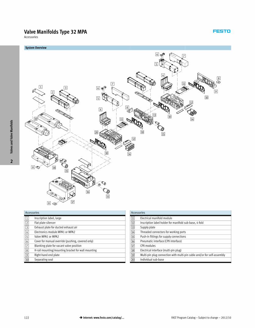
FAST Program Catalog – Subject to change – 2012/10122 � Internet: www.festo.com/catalog/...
Valve Manifolds Type 32 MPAAccessories
System Overview
2
3
5
1 67
9
5
76
aJ
aD
aE
aA
aD
aB
aF
aG8
aH8
aB
aC
aA
8
aI
4
4
aJ
aJ
aJ
aE
aE
bJ
8
Accessories
1 Inscription label, large
2 Flat plate silencer
3 Exhaust plate for ducted exhaust air
4 Electronics module MPA1 or MPA2
5 Valve MPA1 or MPA2
6 Cover for manual override (pushing, covered only)
7 Blanking plate for vacant valve position
8 H-rail mounting/mounting bracket for wall mounting
9 Right-hand end plate
aJ Separating seal
Accessories
aA Electrical manifold module
aB Inscription label holder for manifold sub-base, 4-fold
aC Supply plate
aD Threaded connectors for working ports
aE Push-in fittings for supply connections
aF Pneumatic interface (CPX interface)
aG CPX modules
aH Electrical interface (multi-pin plug)
aI Multi-pin plug connection with multi-pin cable and/or for self-assembly
bJ Individual sub-base
Valv
es a
nd V
alve
Man
ifol
ds
2
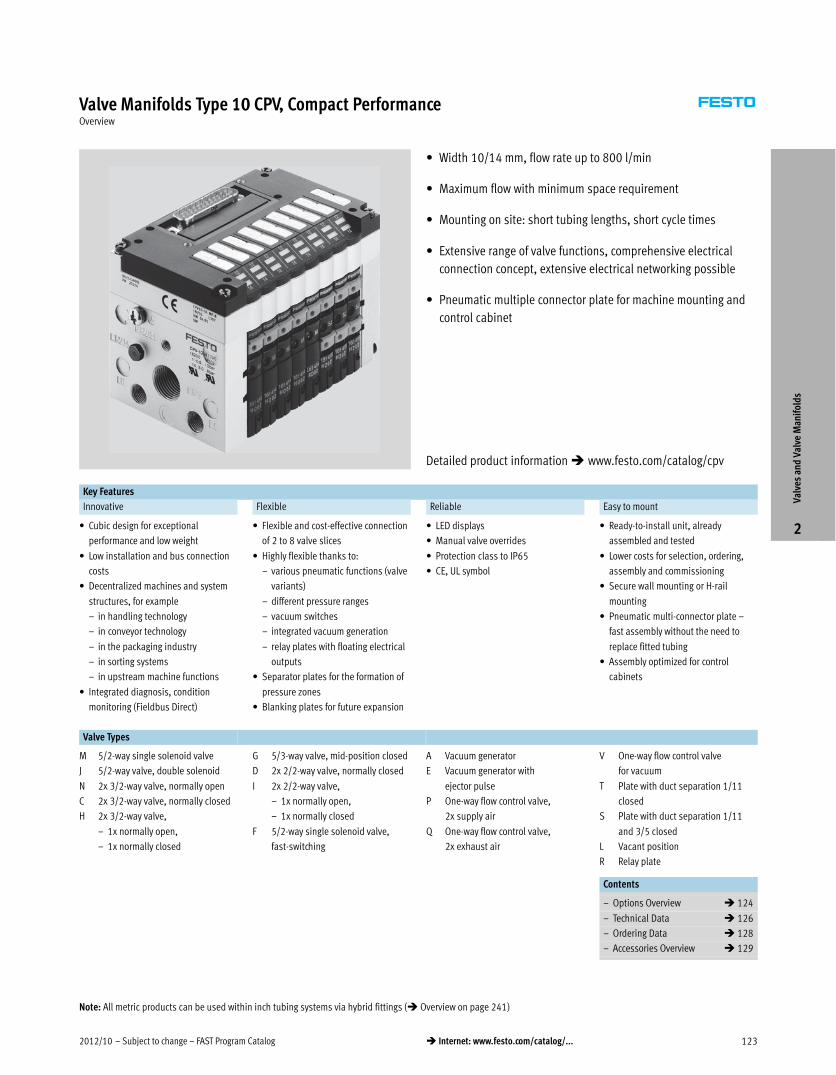
2012/10 – Subject to change – FAST Program Catalog 123� Internet: www.festo.com/catalog/...
Valve Manifolds Type 10 CPV, Compact PerformanceOverview
� Width 10/14 mm, flow rate up to 800 l/min
� Maximum flow with minimum space requirement
� Mounting on site: short tubing lengths, short cycle times
� Extensive range of valve functions, comprehensive electrical
connection concept, extensive electrical networking possible
� Pneumatic multiple connector plate for machine mounting and
control cabinet
Key Features
Innovative Flexible Reliable Easy to mount
� Cubic design for exceptional
performance and low weight
� Low installation and bus connection
costs
� Decentralized machines and system
structures, for example
– in handling technology
– in conveyor technology
– in the packaging industry
– in sorting systems
– in upstream machine functions
� Integrated diagnosis, condition
monitoring (Fieldbus Direct)
� Flexible and cost-effective connection
of 2 to 8 valve slices
� Highly flexible thanks to:
– various pneumatic functions (valve
variants)
– different pressure ranges
– vacuum switches
– integrated vacuum generation
– relay plates with floating electrical
outputs
� Separator plates for the formation of
pressure zones
� Blanking plates for future expansion
� LED displays
� Manual valve overrides
� Protection class to IP65
� CE, UL symbol
� Ready-to-install unit, already
assembled and tested
� Lower costs for selection, ordering,
assembly and commissioning
� Secure wall mounting or H-rail
mounting
� Pneumatic multi-connector plate –
fast assembly without the need to
replace fitted tubing
� Assembly optimized for control
cabinets
Valve Types
M 5/2-way single solenoid valve
J 5/2-way valve, double solenoid
N 2x 3/2-way valve, normally open
C 2x 3/2-way valve, normally closed
H 2x 3/2-way valve,
– 1x normally open,
– 1x normally closed
G 5/3-way valve, mid-position closed
D 2x 2/2-way valve, normally closed
I 2x 2/2-way valve,
– 1x normally open,
– 1x normally closed
F 5/2-way single solenoid valve,
fast-switching
A Vacuum generator
E Vacuum generator with
ejector pulse
P One-way flow control valve,
2x supply air
Q One-way flow control valve,
2x exhaust air
V One-way flow control valve
for vacuum
T Plate with duct separation 1/11
closed
S Plate with duct separation 1/11
and 3/5 closed
L Vacant position
R Relay plate
Contents
– Options Overview � 124
– Technical Data � 126
– Ordering Data � 128
– Accessories Overview � 129
Valv
es a
nd V
alve
Man
ifol
ds
2
Detailed product information � www.festo.com/catalog/cpv
Note: All metric products can be used within inch tubing systems via hybrid fittings (� Overview on page 241)
FAST Program Catalog – Subject to change – 2012/10124 � Internet: www.festo.com/catalog/...
Valve Manifolds Type 10 CPV, Compact PerformanceOverview
Advantages at a Glance
The CPV valve terminal is of unique
design. It permits the flexible
combination of pneumatic performance,
electrical connection technologies and a
wide range of mounting options. The
generously sized flow ducts and
powerful flat plate silencers ensure high
flow rates. This means that even
comparatively large pneumatic cylinders
can be driven with ease.
All valves are in the form of valve slices.
They are optimized for flow performance
and are also extremely compact. Two
functions per valve slice
(e.g. 2x 3/2-way valves) mean that twice
the component density can be achieved.
This saves space and reduces costs.
The cubic design permits exceptional
performance yet a comparatively low
weight. The benefits of this design are
obvious when the valve terminal is used
on a moving installation.
However robustness must not be
sacrificed in favor of compactness. The
connecting thread and mounting
attachments are metallic.
The manual override for the valves can
be adapted for different operating
situations. If, for example, a detenting
manual override is required for
setting-up mode, the manual override
can be easily converted for that
application in a way that rules out
operational errors. The clear, large
labelling system also contributes to the
safe operation of the valve terminal.
A particular plus is the range of
electrical connection technologies
supported. All types of valve activation
are possible, from individual valve
connections up to bus systems with
versatile expansion options. The
integration of electrical input and
output modules permits cost-effective
solutions within the different
installation concepts.
Made-to-measure pneumatics Variable compressed air supply Easy assembly technology
� Exceptional performance and low
weight
� Blanking plates for future expansion
� LED displays
� Manual valve overrides
� Low installation and bus connection
costs
� Protection class to IP65
� Variable compressed air supply that
can be adapted to the relevant
requirements
� Modules for additional compressed
air supply and exhaust
� Choice of assembly on H-rail or
profile/backwall
� Adaptable assembly with connectors
for different tubing diameters
Design Principle
The cubic design provides a clearly
assigned function on each side. Thus,
for example, the electrical connection is
mounted on the top surface. An optional
inscription label holder can be placed
on the front of the valve terminal. The
different combination options ensure
the optimum solution for the task at
hand.
� Pneumatic supply connections on the
left, right or underneath
� Pneumatic working ports and
functional modules (vertical stacking)
underneath
� Manual operation/identification on
the front
� Electrical connection surface on the
top
� Mounting surface at the back or even
at the front via a pneumatic
multi-connector plate
Valves
CPV valves are integrated sub-base
valves, i.e. in addition to the valve
function they contain all of the
pneumatic ducts for supply, exhaust
and the working ports. The supply ducts
are a central component of the valve
slices and allow a direct flow of air
through the valve slices.
This helps achieve maximum flow rates.
All valves have pneumatic pilot control
for optimising performance. The valve
function is based on a piston spool
system with a patented sealing principle
that guarantees its suitability for a wide
range of applications as well as a long
service life.
The pneumatic components and
functions are always identical for all
actuator types. Most functions are also
available in the various valve sizes
(spacing). Restrictions are noted where
applicable.
Pressure zones
Different pressures at port 1 and 11
result in two pressure levels per valve.
This means, for example, that a cylinder
drive can be extended with high
pressure and retracted with low
pressure to save energy.
The maximum number of pressure
zones possible is determined by the
combination of the following
components:
� Use of a separator plate
� End plate pair type
� Valve slice type
You can divide the CPV valve terminal
into 2 to 4 pressure zones by using
separator plates.
Valv
es a
nd V
alve
Man
ifol
ds
2
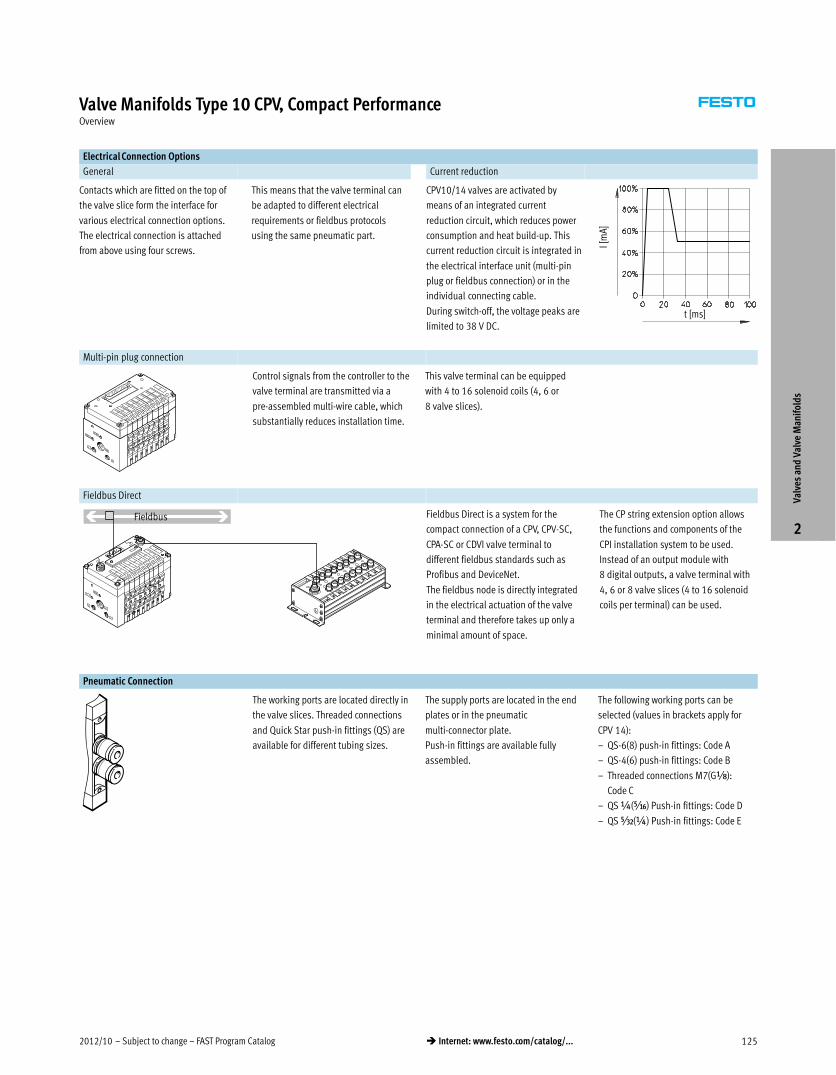
2012/10 – Subject to change – FAST Program Catalog 125� Internet: www.festo.com/catalog/...
Valve Manifolds Type 10 CPV, Compact PerformanceOverview
Electrical Connection Options
General Current reduction
Contacts which are fitted on the top of
the valve slice form the interface for
various electrical connection options.
The electrical connection is attached
from above using four screws.
This means that the valve terminal can
be adapted to different electrical
requirements or fieldbus protocols
using the same pneumatic part.
CPV10/14 valves are activated by
means of an integrated current
reduction circuit, which reduces power
consumption and heat build-up. This
current reduction circuit is integrated in
the electrical interface unit (multi-pin
plug or fieldbus connection) or in the
individual connecting cable.
During switch-off, the voltage peaks are
limited to 38 V DC.t [ms]
I [m
A]
Multi-pin plug connection
Control signals from the controller to the
valve terminal are transmitted via a
pre-assembled multi-wire cable, which
substantially reduces installation time.
This valve terminal can be equipped
with 4 to 16 solenoid coils (4, 6 or
8 valve slices).
Fieldbus Direct
Fieldbus Fieldbus Direct is a system for the
compact connection of a CPV, CPV-SC,
CPA-SC or CDVI valve terminal to
different fieldbus standards such as
Profibus and DeviceNet.
The fieldbus node is directly integrated
in the electrical actuation of the valve
terminal and therefore takes up only a
minimal amount of space.
The CP string extension option allows
the functions and components of the
CPI installation system to be used.
Instead of an output module with
8 digital outputs, a valve terminal with
4, 6 or 8 valve slices (4 to 16 solenoid
coils per terminal) can be used.
Pneumatic Connection
The working ports are located directly in
the valve slices. Threaded connections
and Quick Star push-in fittings (QS) are
available for different tubing sizes.
The supply ports are located in the end
plates or in the pneumatic
multi-connector plate.
Push-in fittings are available fully
assembled.
The following working ports can be
selected (values in brackets apply for
CPV 14):
– QS-6(8) push-in fittings: Code A
– QS-4(6) push-in fittings: Code B
– Threaded connections M7(GÁ):
Code C
– QS ¼(Ä) Push-in fittings: Code D
– QS Â(¼) Push-in fittings: Code E
Valv
es a
nd V
alve
Man
ifol
ds
2
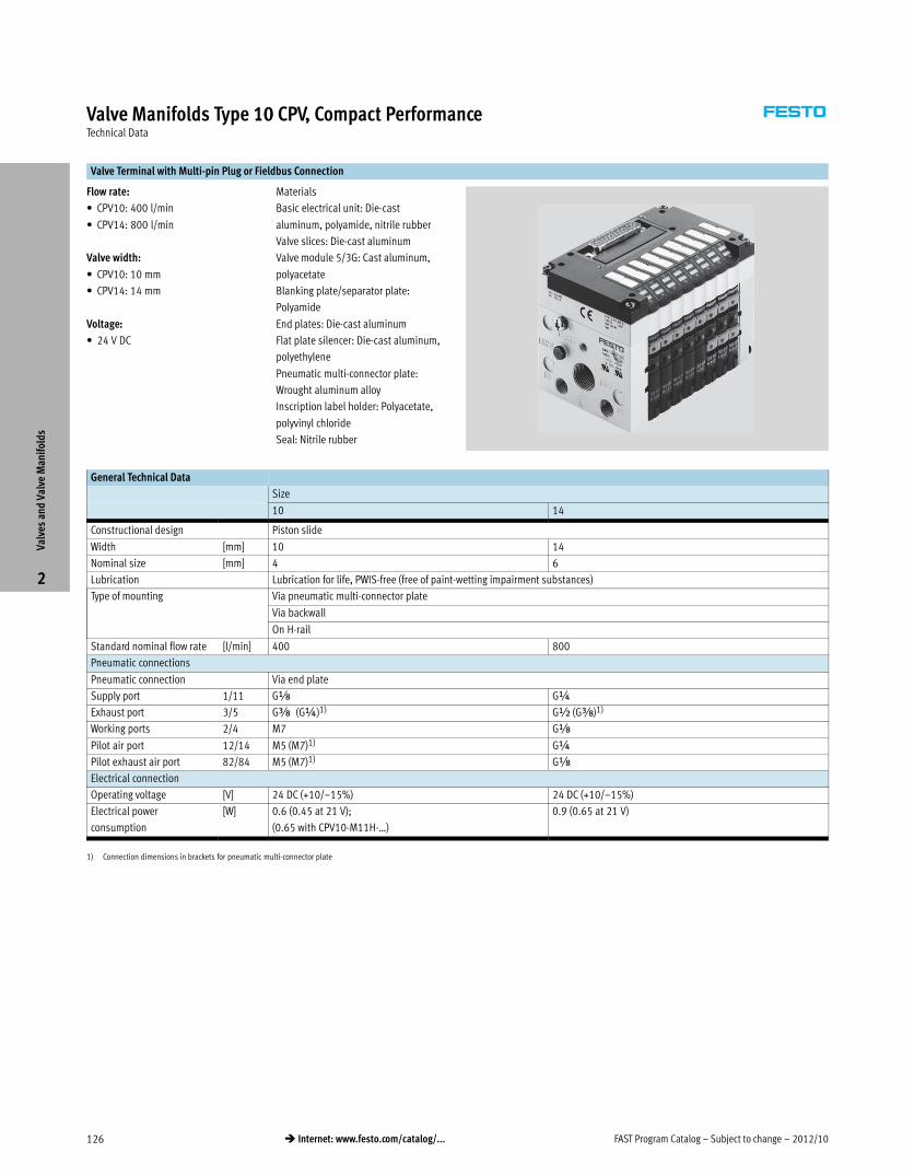
FAST Program Catalog – Subject to change – 2012/10126 � Internet: www.festo.com/catalog/...
Valve Manifolds Type 10 CPV, Compact PerformanceTechnical Data
Valve Terminal with Multi-pin Plug or Fieldbus Connection
Flow rate:
� CPV10: 400 l/min
� CPV14: 800 l/min
Valve width:
� CPV10: 10 mm
� CPV14: 14 mm
Voltage:
� 24 V DC
Materials
Basic electrical unit: Die-cast
aluminum, polyamide, nitrile rubber
Valve slices: Die-cast aluminum
Valve module 5/3G: Cast aluminum,
polyacetate
Blanking plate/separator plate:
Polyamide
End plates: Die-cast aluminum
Flat plate silencer: Die-cast aluminum,
polyethylene
Pneumatic multi-connector plate:
Wrought aluminum alloy
Inscription label holder: Polyacetate,
polyvinyl chloride
Seal: Nitrile rubber
General Technical Data
Size
10 14
Constructional design Piston slide
Width [mm] 10 14
Nominal size [mm] 4 6
Lubrication Lubrication for life, PWIS-free (free of paint-wetting impairment substances)
Type of mounting Via pneumatic multi-connector plate
Via backwall
On H-rail
Standard nominal flow rate [l/min] 400 800
Pneumatic connections
Pneumatic connection Via end plate
Supply port 1/11 Gx G¼
Exhaust port 3/5 Gy (G¼)1) G½ (Gy)1)
Working ports 2/4 M7 Gx
Pilot air port 12/14 M5 (M7)1) G¼
Pilot exhaust air port 82/84 M5 (M7)1) Gx
Electrical connection
Operating voltage [V] 24 DC (+10/–15%) 24 DC (+10/–15%)
Electrical power
consumption
[W] 0.6 (0.45 at 21 V);
(0.65 with CPV10-M11H-…)
0.9 (0.65 at 21 V)
1) Connection dimensions in brackets for pneumatic multi-connector plate
Valv
es a
nd V
alve
Man
ifol
ds
2
2012/10 – Subject to change – FAST Program Catalog 127� Internet: www.festo.com/catalog/...
Valve Manifolds Type 10 CPV, Compact PerformanceTechnical Data
Valve Response Times [ms]
Valve function order code M F J N C CY H G D I A E
CPV10
Switching times on 17 13 – 17 17 17 17 20 15 15 – 15
off 27 17 – 25 25 25 25 30 17 17 – 17
changeover – – 10 – – – – – – – – –
CPV14
Switching times on 25 – – 24 24 – 24 22 13 13 – 13
off 35 – – 30 30 – 30 30 16 16 – 16
changeover – – 12 – – – – – – – – –
Operating and Environmental Conditions
Valve function order code M F J N C CY H G D I A E
Operating medium Compressed air in accordance with ISO 8573-1:2010 [7:4:4]
Note on operating/pilot medium Operation with lubricated medium possible (in which case lubricated operation will always be required)
Grade of filtration [μm] 40 (average pore size)
Operating pressure [bar] –0.9 … +10 +0.1 … +10 –0.9 … +10
Operating pressure
for valve terminal with internal
pilot air supply
[bar] 3 … 8
Pilot pressure [bar] 3 … 8
Ambient temperature [°C] –5 … +50 (vacuum generators: 0 … +50)
Storage temperature [°C] –20 … +40
Relative air humidity at 25 °C [%] 95 with no condensation
Corrosion resistance class CRC1) 2 1
1) Corrosion resistance class 2 as per Festo standard 940 070
Components subject to moderate corrosion stress. Externally visible parts with primarily decorative surface requirements which are in direct contact with a normal industrial environment or media such as coolants or lubricating
agents.
Valv
es a
nd V
alve
Man
ifol
ds
2
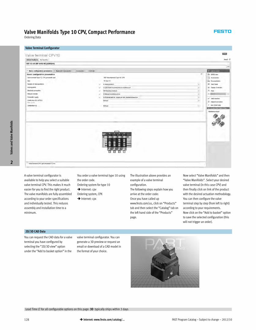
FAST Program Catalog – Subject to change – 2012/10128 � Internet: www.festo.com/catalog/...
Valve Manifolds Type 10 CPV, Compact PerformanceOrdering Data
Valve Terminal Configurator
A valve terminal configurator is
available to help you select a suitable
valve terminal CPV. This makes it much
easier for you to find the right product.
The valve manifolds are fully assembled
according to your order specifications
and individually tested. This reduces
assembly and installation time to a
minimum.
You order a valve terminal type 10 using
the order code.
Ordering system for type 10
� Internet: cpv
Ordering system, CPX
� Internet: cpx
The illustration above provides an
example of a valve terminal
configuration.
The following steps explain how you
arrive at the order code:
Once you have called up
www.festo.com/us, click on “Products”
tab and then select the “Catalog” tab on
the left hand side of the “Products”
page.
Now select “Valve Manifolds” and then
“Valve Manifolds”. Select your desired
valve terminal (in this case CPV) and
then finally click on link of the product
with the desired actuation methodology.
You can then configure the valve
terminal step by step (from left to right)
according to your requirements.
Now click on the “Add to basket” option
to save the selected configuration (this
will not trigger an order).
2D/3D CAD Data
You can request the CAD data for a valve
terminal you have configured by
selecting the “2D/3D view” option
under the “Add to basket option” in the
valve terminal configurator. You can
generate a 3D preview or request an
email or download of a CAD model in
the format of your choice.
Valv
es a
nd V
alve
Man
ifol
ds
2
Lead Time LT for all configurable options on this page: 3D typically ships within 3 days
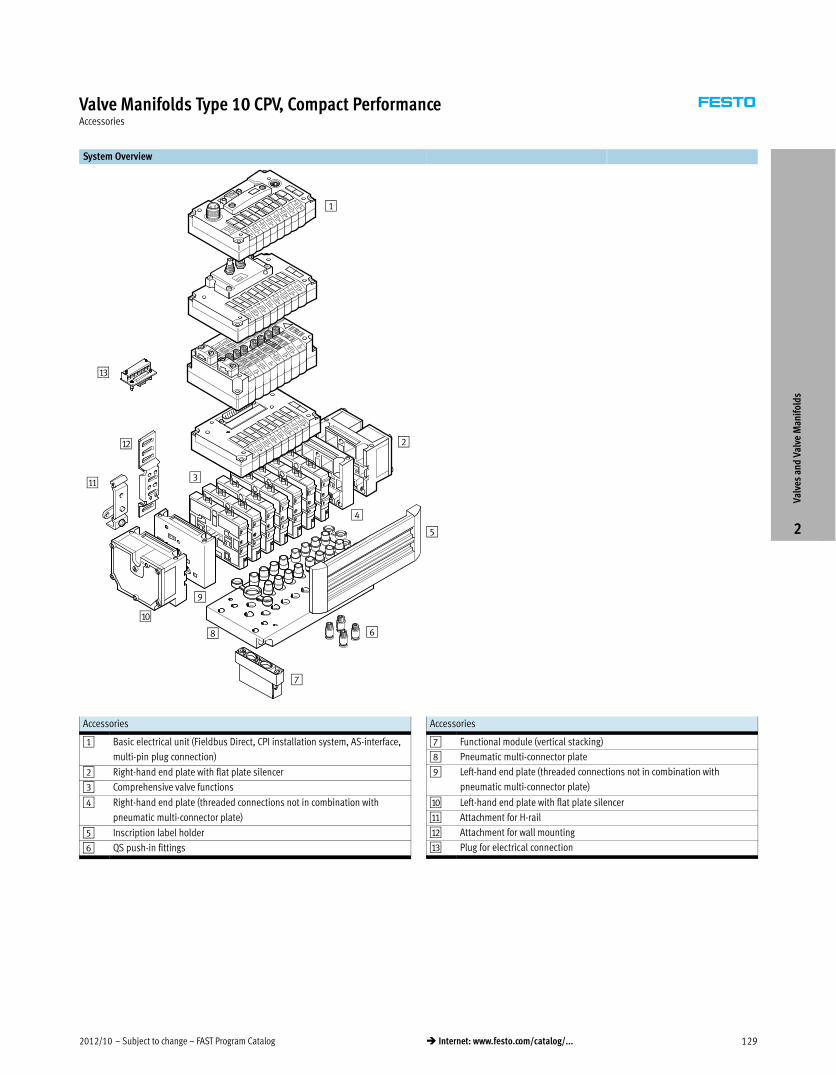
2012/10 – Subject to change – FAST Program Catalog 129� Internet: www.festo.com/catalog/...
Valve Manifolds Type 10 CPV, Compact PerformanceAccessories
System Overview
9
2
5
4
6
7
8
3
1
aJ
aA
aB
aC
Accessories
1 Basic electrical unit (Fieldbus Direct, CPI installation system, AS-interface,
multi-pin plug connection)
2 Right-hand end plate with flat plate silencer
3 Comprehensive valve functions
4 Right-hand end plate (threaded connections not in combination with
pneumatic multi-connector plate)
5 Inscription label holder
6 QS push-in fittings
Accessories
7 Functional module (vertical stacking)
8 Pneumatic multi-connector plate
9 Left-hand end plate (threaded connections not in combination with
pneumatic multi-connector plate)
aJ Left-hand end plate with flat plate silencer
aA Attachment for H-rail
aB Attachment for wall mounting
aC Plug for electrical connection
Valv
es a
nd V
alve
Man
ifol
ds
2
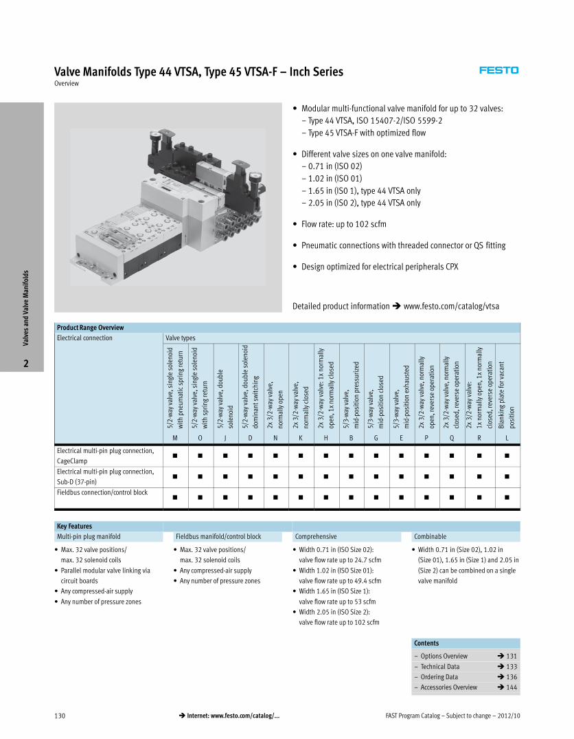
FAST Program Catalog – Subject to change – 2012/10130 � Internet: www.festo.com/catalog/...
Valve Manifolds Type 44 VTSA, Type 45 VTSA-F – Inch SeriesOverview
� Modular multi-functional valve manifold for up to 32 valves:
– Type 44 VTSA, ISO 15407-2/ISO 5599-2
– Type 45 VTSA-F with optimized flow
� Different valve sizes on one valve manifold:
– 0.71 in (ISO 02)
– 1.02 in (ISO 01)
– 1.65 in (IS0 1), type 44 VTSA only
– 2.05 in (IS0 2), type 44 VTSA only
� Flow rate: up to 102 scfm
� Pneumatic connections with threaded connector or QS fitting
� Design optimized for electrical peripherals CPX
Product Range Overview
Electrical connection Valve types
5/2
-way
val
ve, s
ingl
e so
leno
id
wit
h pn
eum
atic
spr
ing
retu
rn
5/2
-way
val
ve, s
ingl
e so
leno
id
wit
h sp
ring
retu
rn
5/2
-way
val
ve, d
oubl
e
sole
noid
5/2
-way
val
ve, d
oubl
e so
leno
id
dom
inan
t sw
itch
ing
2x
3/2
-way
val
ve,
norm
ally
ope
n
2x
3/2
-way
val
ve,
norm
ally
clo
sed
2x
3/2
-way
val
ve: 1
x no
rmal
ly
open
, 1x
norm
ally
clo
sed
5/3
-way
val
ve,
mid
-pos
itio
n pr
essu
rize
d
5/3
-way
val
ve,
mid
-pos
itio
n cl
osed
5/3
-way
val
ve,
mid
-pos
itio
n ex
haus
ted
2x
3/2
-way
val
ve, n
orm
ally
open
, rev
erse
ope
rati
on
2x
3/2
-way
val
ve, n
orm
ally
clos
ed, r
ever
se o
pera
tion
2x
3/2
-way
val
ve:
1x
norm
ally
ope
n, 1
x no
rmal
ly
clos
ed, r
ever
se o
pera
tion
Bla
nkin
g pl
ate
for
vaca
nt
posi
tion
M O J D N K H B G E P Q R L
Electrical multi-pin plug connection,
CageClamp� � � � � � � � � � � � � �
Electrical multi-pin plug connection,
Sub-D (37-pin)� � � � � � � � � � � � � �
Fieldbus connection/control block� � � � � � � � � � � � � �
Key Features
Multi-pin plug manifold Fieldbus manifold/control block Comprehensive Combinable
� Max. 32 valve positions/
max. 32 solenoid coils
� Parallel modular valve linking via
circuit boards
� Any compressed-air supply
� Any number of pressure zones
� Max. 32 valve positions/
max. 32 solenoid coils
� Any compressed-air supply
� Any number of pressure zones
� Width 0.71 in (ISO Size 02):
valve flow rate up to 24.7 scfm
� Width 1.02 in (ISO Size 01):
valve flow rate up to 49.4 scfm
� Width 1.65 in (ISO Size 1):
valve flow rate up to 53 scfm
� Width 2.05 in (ISO Size 2):
valve flow rate up to 102 scfm
� Width 0.71 in (Size 02), 1.02 in
(Size 01), 1.65 in (Size 1) and 2.05 in
(Size 2) can be combined on a single
valve manifold
Contents
– Options Overview � 131
– Technical Data � 133
– Ordering Data � 136
– Accessories Overview � 144
Valv
es a
nd V
alve
Man
ifol
ds
2
Detailed product information � www.festo.com/catalog/vtsa
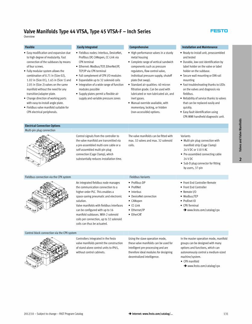
2012/10 – Subject to change – FAST Program Catalog 131� Internet: www.festo.com/catalog/...
Valve Manifolds Type 44 VTSA, Type 45 VTSA-F – Inch SeriesOverview
Flexible Easily Integrated Comprehensive Installation and Maintenance
� Easy modification and expansion due
to high degree of modularity. Fast
connection of the subbases by means
of four screws.
� Fully modular system allows the
combination of 0.71 in (Size 02),
1.02 in (Size 01), 1.65 in (Size 1) and
2.05 in (Size 2) valves on the same
manifold without the need for any
transition/adapter plate.
� Change direction of working ports
with easy-to-install angle plate.
� Fieldbus valve manifold suitable for
CPX electrical peripherals.
� Fieldbus nodes: Interbus, DeviceNet,
Profibus DP, CANopen, CC-Link via
CPX terminal
� Ethernet: Modbus/TCP, EtherNet/IP,
TCP/IP via CPX terminal
� Full complement of CPX I/O modules
� Expandable up to 32 solenoid coils
� Integration of a wide range of function
modules possible
� Supply plates permit a flexible air
supply and variable pressure zones
� High-performance valves in a sturdy
metal housing
� Complete range of vertical sandwich
components such as pressure
regulators, flow control valve,
individual pressure supply, shutoff
plate (hot swap).
� Standard air qualities: 40 micron
filtration grade. Can be used with
lubricated or non-lubricated air, and
inert gases.
� Manual override available, with
momentary, locking, or hidden
(non-accessible) options.
� Ready-to-install unit, preassembled
and tested
� Durable, low cost identification by
label holder on the valve or label
holder on the subbase.
� Secure wall mounting or DIN rail
mounting
� Fast troubleshooting thanks to LEDs
on the valves and diagnosis via
fieldbus.
� Reliability of service thanks to valves
that can be replaced easily and
quickly.
� Easy fault identification using
CPX-MMI handheld diagnostic unit.
Electrical Connection Options
Multi-pin plug connection
Control signals from the controller to
the valve manifold are transmitted via
a pre-assembled multi-core cable or a
self-assembled multi-pin plug
connection (Cage Clamp), which
substantially reduces installation time.
The valve manifolds can be fitted with
max. 32 valves and max. 32 solenoid
coils.
Variants
� Multi-pin plug connection with
manifold strip (Cage Clamp)
24 V DC or 110 V AC
� Pre-assembled connecting cable
24 V DC
� Sub-D plug connector for fitting
by users, 37-pin
Fieldbus connection via the CPX system Fieldbus Variants
An integrated fieldbus node manages
the communication connection to a
higher-order PLC. This enables a
space-saving pneumatic and electronic
solution.
Valve manifolds with fieldbus interfaces
can be configured with up to 16
manifold subbases. With 2 solenoid
coils per connection, up to 32 solenoid
coils can thus be actuated.
� Profibus-DP
� ProfiNet
� Interbus
� DeviceNet connection
� CANopen
� CC-Link
� Ethernet/IP
� EtherCAT
� Front End Controller Remote
� Front End Controller
� Remote I/O
� Modbus/TCP
� Profinet IO
� CPX-Terminal
� www.festo.com/catalog/cpx
Control block connection via the CPX system
Controllers integrated in the Festo
valve manifolds permit the construction
of stand-alone control units to IP65,
without control cabinets.
Using the slave operation mode,
these valve manifolds can be used for
intelligent pre-processing and are
therefore ideal modules for designing
decentralized intelligence.
In the master operation mode, manifold
groups can be designed with many
options and functions, which can
autonomously control a medium-sized
machine/system.
� CPX manifold
� www.festo.com/catalog/cpx
Valv
es a
nd V
alve
Man
ifol
ds
2
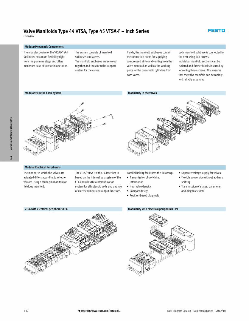
FAST Program Catalog – Subject to change – 2012/10132 � Internet: www.festo.com/catalog/...
Valve Manifolds Type 44 VTSA, Type 45 VTSA-F – Inch SeriesOverview
Modular Pneumatic Components
The modular design of the VTSA/VTSA-F
facilitates maximum flexibility right
from the planning stage and offers
maximum ease of service in operation.
The system consists of manifold
subbases and valves.
The manifold subbases are screwed
together and thus form the support
system for the valves.
Inside, the manifold subbases contain
the connection ducts for supplying
compressed air to and venting from the
valve manifold as well as the working
ports for the pneumatic cylinders from
each valve.
Each manifold subbase is connected to
the next using four screws.
Individual manifold sections can be
isolated and further blocks inserted by
loosening these screws. This ensures
that the valve manifold can be rapidly
and reliably expanded.
Modularity in the basic system Modularity in the valves
Modular Electrical Peripherals
The manner in which the valves are
actuated differs according to whether
you are using a multi-pin manifold or
fieldbus manifold.
The VTSA/-VTSA-F with CPX interface is
based on the internal bus system of the
CPX and uses this communication
system for all solenoid coils and a range
of electrical input and output functions.
Parallel linking facilitates the following:
� Transmission of switching
information
� High valve density
� Compact design
� Position-based diagnosis
� Separate voltage supply for valves
� Flexible conversion without address
shifting
� Transmission of status, parameter
and diagnostic data
VTSA with electrical peripherals CPX Modularity with electrical peripherals CPX
Valv
es a
nd V
alve
Man
ifol
ds
2
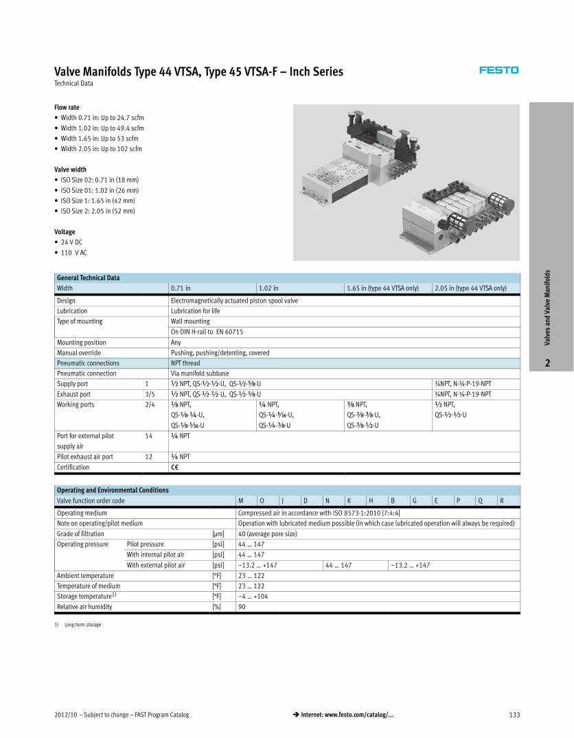
2012/10 – Subject to change – FAST Program Catalog 133� Internet: www.festo.com/catalog/...
Valve Manifolds Type 44 VTSA, Type 45 VTSA-F – Inch SeriesTechnical Data
Flow rate
� Width 0.71 in: Up to 24.7 scfm
� Width 1.02 in: Up to 49.4 scfm
� Width 1.65 in: Up to 53 scfm
� Width 2.05 in: Up to 102 scfm
Valve width
� ISO Size 02: 0.71 in (18 mm)
� ISO Size 01: 1.02 in (26 mm)
� ISO Size 1: 1.65 in (42 mm)
� ISO Size 2: 2.05 in (52 mm)
Voltage
� 24 V DC
� 110 V AC
General Technical Data
Width 0.71 in 1.02 in 1.65 in (type 44 VTSA only) 2.05 in (type 44 VTSA only)
Design Electromagnetically actuated piston spool valve
Lubrication Lubrication for life
Type of mounting Wall mounting
On DIN H-rail to EN 60715
Mounting position Any
Manual override Pushing, pushing/detenting, covered
Pneumatic connections NPT thread
Pneumatic connection Via manifold subbase
Supply port 1 ½ NPT, QS-½-½-U, QS-½-Æ-U ¾NPT, N-¾-P-19-NPT
Exhaust port 3/5 ½ NPT, QS-½-½-U, QS-½-Æ-U ¾NPT, N-¾-P-19-NPT
Working ports 2/4 x NPT,
QS-x-¼-U,
QS-x-Ä-U
¼ NPT,
QS-¼-Ä-U,
QS-¼-y-U
y NPT,
QS-y-y-U,
QS-y-½-U
½ NPT,
QS-½-½-U
Port for external pilot
supply air
14 ¼ NPT
Pilot exhaust air port 12 ¼ NPT
Certification •
Operating and Environmental Conditions
Valve function order code M O J D N K H B G E P Q R
Operating medium Compressed air in accordance with ISO 8573-1:2010 [7:4:4]
Note on operating/pilot medium Operation with lubricated medium possible (in which case lubricated operation will always be required)
Grade of filtration [μm] 40 (average pore size)
Operating pressure Pilot pressure [psi] 44 … 147
With internal pilot air [psi] 44 … 147
With external pilot air [psi] –13.2 … +147 44 … 147 –13.2 … +147
Ambient temperature [°F] 23 … 122
Temperature of medium [°F] 23 … 122
Storage temperature1) [°F] –4 … +104
Relative air humidity [%] 90
1) Long-term storage
Valv
es a
nd V
alve
Man
ifol
ds
2
FAST Program Catalog – Subject to change – 2012/10134 � Internet: www.festo.com/catalog/...
Valve Manifolds Type 44 VTSA, Type 45 VTSA-F – Inch SeriesTechnical Data
Standard Nominal Flow Rate [scfm] – Type 44 VTSA
Valve function order code M O J D N K H B G E P Q R
Width 0.71 in
Flow rate of valve 26.5 21.2 24.71), 15.22) 21.2
Flow rate of valve on individual subbase 21.2 17.7 19.41), 12.72) 17.7
Flow rate of valve on valve manifold 19.4 14.1 15.91), 10.62) 14.1
Width 1.02 in
Flow rate of valve 49.4 44.1 49.41), 35.32) 44.1
Flow rate of valve on individual subbase 42.4 38.8 42.41), 30.02) 35.3
Flow rate of valve on valve manifold 38.8 31.8 35.31), 24.72) 31.8
Width 1.65 in
Flow rate of valve 63.5 49.4 60.01), 26.52) 49.4
Flow rate of valve on individual subbase 45.9 42.4 42.41), 28.22) 42.4
Flow rate of valve on valve manifold 53.0 42.4 49.41), 28.22) 42.4
Width 2.05 in
Flow rate of valve 141.2 105.9 1271), 602) 105.9
Flow rate of valve on individual subbase 113 88.3 105.91), 602) 88.3
Flow rate of valve on valve manifold 102.4 84.7 98.81), 602) 84.7
1) Switching position
2) Mid-position
Standard Nominal Flow Rate [scfm] – Type 45 VTSA-F
Valve function order code M O J D N K H B G E P Q R
Width 0.71 in
Flow rate of valve 26.5 21.2 17.71), 11.62) 21.2
Flow rate of valve on valve manifold 24.7 19.4 17.71), 11.62) 19.4
Width 1.02 in
Flow rate of valve 49.4 44.1 49.41), 24.72) 44.1
Flow rate of valve on valve manifold 47.7 40.6 47.71), 24.72) 40.6
1) Switching position
2) Mid-position
Valve Response Times [ms]
Valve function order code M O J D N K H B G E P Q R
Width 0.71 in
Response times on 22 12 – – 12 12 12 15 15 15 25 25 25
off 28 38 – – 30 30 30 44 44 44 12 12 12
changeover – – 11 11 – – – 22 22 22 – – –
Width 1.02 in
Response times on 25 20 – – 20 20 20 22 22 22 32 32 32
off 45 65 – – 38 38 38 65 65 65 30 30 30
changeover – – 18 18 – – – 33 33 33 – – –
Width 1.65 in (type 44 VTSA only)
Response times on 27 22 – – 20 20 20 22 22 22 34 34 34
off 45 60 – – 38 38 38 65 65 65 28 28 28
changeover – – 16 16 – – – – – – – – –
Width 2.05 in (type 44 VTSA only)
Response times on 40 20 – – 20 20 20 30 30 30 50 50 50
off 45 60 – – 35 35 35 100 100 100 65 65 65
changeover – – 18 18 – – – – – – – – –
Valv
es a
nd V
alve
Man
ifol
ds
2
2012/10 – Subject to change – FAST Program Catalog 135� Internet: www.festo.com/catalog/...
Valve Manifolds Type 44 VTSA, Type 45 VTSA-F – Inch SeriesTechnical Data
Electrical Data – VTSA/VTSA-F with CPX Manifold
0.71 in 1.02 in 1.65 in (Type 44 VTSA only) 2.5 in (Type 44 VTSA only)
Voltage supply for electronics/sensors (pin 1)
Operating voltage [V] 24 DC ±10%
Steady state current
consumption at 24 V DC
[mA] 20
Duty cycle 100%
Load voltage supply for valves (pin 2)
Operating voltage [V] 24 DC ±10%
Diagnostic message
undervoltage VOFF, load voltage
outside function range
[V] 21.6 … 21.5
Protection class to EN 60529 IP65 (for all types of signal transmission in assembled state)
Power consumption at 24 V DC
2x 3/2-way valve [W] 1.3 4.6
5/2-way valve, 5/3-way valve [W] 1.6 4.6
Electrical Data – VTSA/VTSA-F with Multi-pin Plug Connection
0.71 in 1.02 in 1.65 in (Type 44 VTSA only) 2.05 in (Type 44 VTSA only)
Load voltage supply for valves
Operating voltage [V] 24 DC ±10%
110 AC ±10% (50 … 60 Hz)
Duty cycle 100%
Protection class to EN 60529 IP65 (for all types of signal transmission in assembled state), NEMA 4
Power consumption at 24 V DC
2x 3/2-way valve [W] 1.3 4.6
5/2-way valve, 5/3-way valve [W] 1.6 4.6
Power consumption at 110 V AC
2x 3/2-way valve [VA] 1
5/2-way valve, 5/3-way valve [VA] 1.6
Materials
0.71 in 1.02 in 1.65 in (Type 44 VTSA only) 2.05 in (Type 44 VTSA only)
Manifold subbase Die-cast aluminum
Valve Die-cast aluminum, reinforced polyamide
Seals Nitrile rubber, elastomer (support made of steel)
Supply plate Die-cast aluminum
Right-hand end plate Die-cast aluminum
Left-hand pneumatic interface Die-cast aluminum
Flow control plate Die-cast aluminum
Pressure regulator plate Die-cast aluminum, reinforced polyamide
Multi-pin connection block Die-cast aluminum
Cover for the pneumatic interface and
multi-pin plug connection
Wellamid, reinforced polyamideVa
lves
and
Val
ve M
anif
olds
2
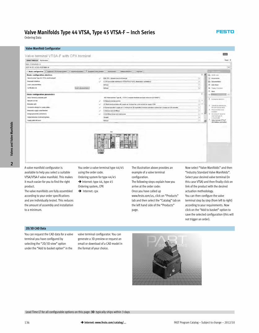
FAST Program Catalog – Subject to change – 2012/10136 � Internet: www.festo.com/catalog/...
Valve Manifolds Type 44 VTSA, Type 45 VTSA-F – Inch SeriesOrdering Data
Valve Manifold Configurator
A valve manifold configurator is
available to help you select a suitable
VTSA/VTSA-F valve manifold. This makes
it much easier for you to find the right
product.
The valve manifolds are fully assembled
according to your order specifications
and are individually tested. This reduces
the amount of assembly and installation
to a minimum.
You order a valve terminal type 44/45
using the order code.
Ordering system for type 44/45
� Internet: type 44, type 45
Ordering system, CPX
� Internet: cpx
The illustration above provides an
example of a valve terminal
configuration.
The following steps explain how you
arrive at the order code:
Once you have called up
www.festo.com/us, click on “Products”
tab and then select the “Catalog” tab on
the left hand side of the “Products”
page.
Now select “Valve Manifolds” and then
“Industry Standard Valve Manifolds”.
Select your desired valve terminal (in
this case VTSA) and then finally click on
link of the product with the desired
actuation methodology.
You can then configure the valve
terminal step by step (from left to right)
according to your requirements. Now
click on the “Add to basket” option to
save the selected configuration (this will
not trigger an order).
2D/3D CAD Data
You can request the CAD data for a valve
terminal you have configured by
selecting the “2D/3D view” option
under the “Add to basket option” in the
valve terminal configurator. You can
generate a 3D preview or request an
email or download of a CAD model in
the format of your choice.
Valv
es a
nd V
alve
Man
ifol
ds
2
Lead Time LT for all configurable options on this page: 3D typically ships within 3 days
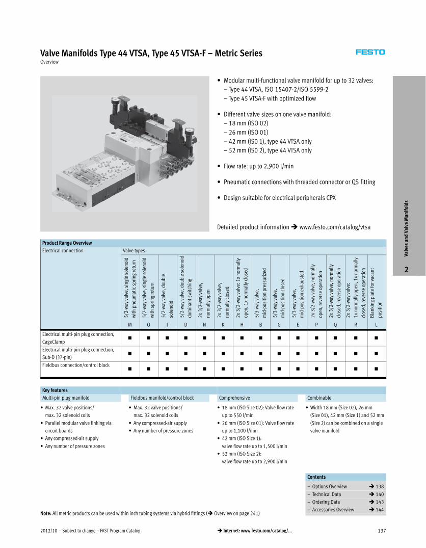
2012/10 – Subject to change – FAST Program Catalog 137� Internet: www.festo.com/catalog/...
Valve Manifolds Type 44 VTSA, Type 45 VTSA-F – Metric SeriesOverview
� Modular multi-functional valve manifold for up to 32 valves:
– Type 44 VTSA, ISO 15407-2/ISO 5599-2
– Type 45 VTSA-F with optimized flow
� Different valve sizes on one valve manifold:
– 18 mm (ISO 02)
– 26 mm (ISO 01)
– 42 mm (IS0 1), type 44 VTSA only
– 52 mm (IS0 2), type 44 VTSA only
� Flow rate: up to 2,900 l/min
� Pneumatic connections with threaded connector or QS fitting
� Design suitable for electrical peripherals CPX
Product Range Overview
Electrical connection Valve types
5/2
-way
val
ve, s
ingl
e so
leno
id
wit
h pn
eum
atic
spr
ing
retu
rn
5/2
-way
val
ve, s
ingl
e so
leno
id
wit
h sp
ring
retu
rn
5/2
-way
val
ve, d
oubl
e
sole
noid
5/2
-way
val
ve, d
oubl
e so
leno
id
dom
inan
t sw
itch
ing
2x
3/2
-way
val
ve,
norm
ally
ope
n
2x
3/2
-way
val
ve,
norm
ally
clo
sed
2x
3/2
-way
val
ve: 1
x no
rmal
ly
open
, 1x
norm
ally
clo
sed
5/3
-way
val
ve,
mid
-pos
itio
n pr
essu
rize
d
5/3
-way
val
ve,
mid
-pos
itio
n cl
osed
5/3
-way
val
ve,
mid
-pos
itio
n ex
haus
ted
2x
3/2
-way
val
ve, n
orm
ally
open
, rev
erse
ope
rati
on
2x
3/2
-way
val
ve, n
orm
ally
clos
ed, r
ever
se o
pera
tion
2x
3/2
-way
val
ve:
1x
norm
ally
ope
n, 1
x no
rmal
ly
clos
ed, r
ever
se o
pera
tion
Bla
nkin
g pl
ate
for
vaca
nt
posi
tion
M O J D N K H B G E P Q R L
Electrical multi-pin plug connection,
CageClamp� � � � � � � � � � � � � �
Electrical multi-pin plug connection,
Sub-D (37-pin)� � � � � � � � � � � � � �
Fieldbus connection/control block� � � � � � � � � � � � � �
Key features
Multi-pin plug manifold Fieldbus manifold/control block Comprehensive Combinable
� Max. 32 valve positions/
max. 32 solenoid coils
� Parallel modular valve linking via
circuit boards
� Any compressed-air supply
� Any number of pressure zones
� Max. 32 valve positions/
max. 32 solenoid coils
� Any compressed-air supply
� Any number of pressure zones
� 18 mm (ISO Size 02): Valve flow rate
up to 550 l/min
� 26 mm (ISO Size 01): Valve flow rate
up to 1,100 l/min
� 42 mm (ISO Size 1):
valve flow rate up to 1,500 l/min
� 52 mm (ISO Size 2):
valve flow rate up to 2,900 l/min
� Width 18 mm (Size 02), 26 mm
(Size 01), 42 mm (Size 1) and 52 mm
(Size 2) can be combined on a single
valve manifold
Contents
– Options Overview � 138
– Technical Data � 140
– Ordering Data � 143
– Accessories Overview � 144
Valv
es a
nd V
alve
Man
ifol
ds
2
Detailed product information � www.festo.com/catalog/vtsa
Note: All metric products can be used within inch tubing systems via hybrid fittings (� Overview on page 241)
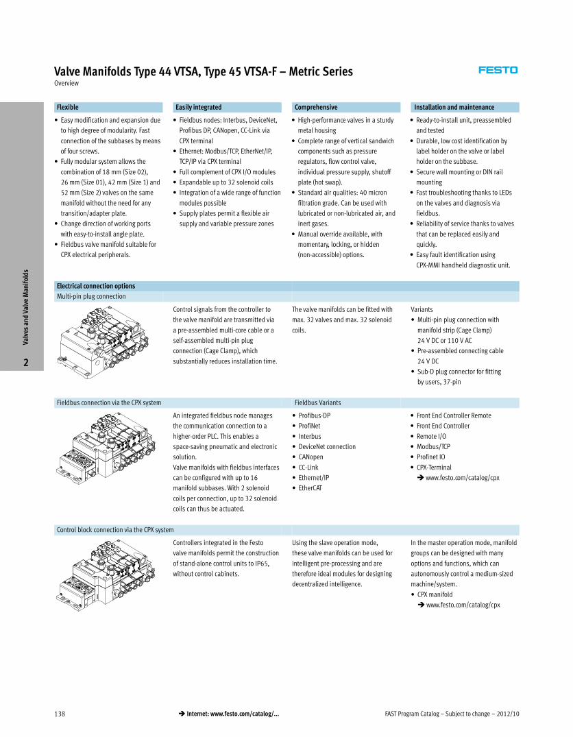
FAST Program Catalog – Subject to change – 2012/10138 � Internet: www.festo.com/catalog/...
Valve Manifolds Type 44 VTSA, Type 45 VTSA-F – Metric SeriesOverview
Flexible Easily integrated Comprehensive Installation and maintenance
� Easy modification and expansion due
to high degree of modularity. Fast
connection of the subbases by means
of four screws.
� Fully modular system allows the
combination of 18 mm (Size 02),
26 mm (Size 01), 42 mm (Size 1) and
52 mm (Size 2) valves on the same
manifold without the need for any
transition/adapter plate.
� Change direction of working ports
with easy-to-install angle plate.
� Fieldbus valve manifold suitable for
CPX electrical peripherals.
� Fieldbus nodes: Interbus, DeviceNet,
Profibus DP, CANopen, CC-Link via
CPX terminal
� Ethernet: Modbus/TCP, EtherNet/IP,
TCP/IP via CPX terminal
� Full complement of CPX I/O modules
� Expandable up to 32 solenoid coils
� Integration of a wide range of function
modules possible
� Supply plates permit a flexible air
supply and variable pressure zones
� High-performance valves in a sturdy
metal housing
� Complete range of vertical sandwich
components such as pressure
regulators, flow control valve,
individual pressure supply, shutoff
plate (hot swap).
� Standard air qualities: 40 micron
filtration grade. Can be used with
lubricated or non-lubricated air, and
inert gases.
� Manual override available, with
momentary, locking, or hidden
(non-accessible) options.
� Ready-to-install unit, preassembled
and tested
� Durable, low cost identification by
label holder on the valve or label
holder on the subbase.
� Secure wall mounting or DIN rail
mounting
� Fast troubleshooting thanks to LEDs
on the valves and diagnosis via
fieldbus.
� Reliability of service thanks to valves
that can be replaced easily and
quickly.
� Easy fault identification using
CPX-MMI handheld diagnostic unit.
Electrical connection options
Multi-pin plug connection
Control signals from the controller to
the valve manifold are transmitted via
a pre-assembled multi-core cable or a
self-assembled multi-pin plug
connection (Cage Clamp), which
substantially reduces installation time.
The valve manifolds can be fitted with
max. 32 valves and max. 32 solenoid
coils.
Variants
� Multi-pin plug connection with
manifold strip (Cage Clamp)
24 V DC or 110 V AC
� Pre-assembled connecting cable
24 V DC
� Sub-D plug connector for fitting
by users, 37-pin
Fieldbus connection via the CPX system Fieldbus Variants
An integrated fieldbus node manages
the communication connection to a
higher-order PLC. This enables a
space-saving pneumatic and electronic
solution.
Valve manifolds with fieldbus interfaces
can be configured with up to 16
manifold subbases. With 2 solenoid
coils per connection, up to 32 solenoid
coils can thus be actuated.
� Profibus-DP
� ProfiNet
� Interbus
� DeviceNet connection
� CANopen
� CC-Link
� Ethernet/IP
� EtherCAT
� Front End Controller Remote
� Front End Controller
� Remote I/O
� Modbus/TCP
� Profinet IO
� CPX-Terminal
� www.festo.com/catalog/cpx
Control block connection via the CPX system
Controllers integrated in the Festo
valve manifolds permit the construction
of stand-alone control units to IP65,
without control cabinets.
Using the slave operation mode,
these valve manifolds can be used for
intelligent pre-processing and are
therefore ideal modules for designing
decentralized intelligence.
In the master operation mode, manifold
groups can be designed with many
options and functions, which can
autonomously control a medium-sized
machine/system.
� CPX manifold
� www.festo.com/catalog/cpx
Valv
es a
nd V
alve
Man
ifol
ds
2
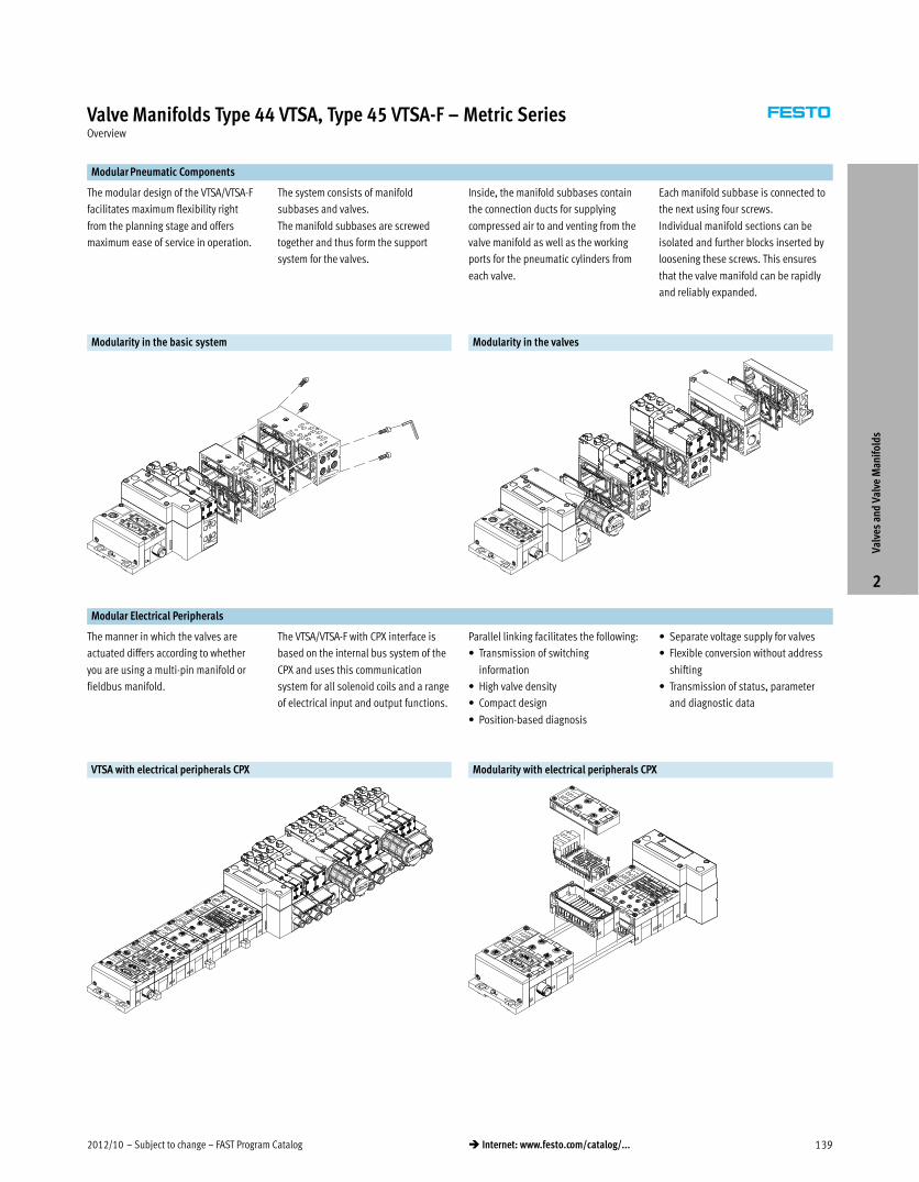
2012/10 – Subject to change – FAST Program Catalog 139� Internet: www.festo.com/catalog/...
Valve Manifolds Type 44 VTSA, Type 45 VTSA-F – Metric SeriesOverview
Modular Pneumatic Components
The modular design of the VTSA/VTSA-F
facilitates maximum flexibility right
from the planning stage and offers
maximum ease of service in operation.
The system consists of manifold
subbases and valves.
The manifold subbases are screwed
together and thus form the support
system for the valves.
Inside, the manifold subbases contain
the connection ducts for supplying
compressed air to and venting from the
valve manifold as well as the working
ports for the pneumatic cylinders from
each valve.
Each manifold subbase is connected to
the next using four screws.
Individual manifold sections can be
isolated and further blocks inserted by
loosening these screws. This ensures
that the valve manifold can be rapidly
and reliably expanded.
Modularity in the basic system Modularity in the valves
Modular Electrical Peripherals
The manner in which the valves are
actuated differs according to whether
you are using a multi-pin manifold or
fieldbus manifold.
The VTSA/VTSA-F with CPX interface is
based on the internal bus system of the
CPX and uses this communication
system for all solenoid coils and a range
of electrical input and output functions.
Parallel linking facilitates the following:
� Transmission of switching
information
� High valve density
� Compact design
� Position-based diagnosis
� Separate voltage supply for valves
� Flexible conversion without address
shifting
� Transmission of status, parameter
and diagnostic data
VTSA with electrical peripherals CPX Modularity with electrical peripherals CPX
Valv
es a
nd V
alve
Man
ifol
ds
2
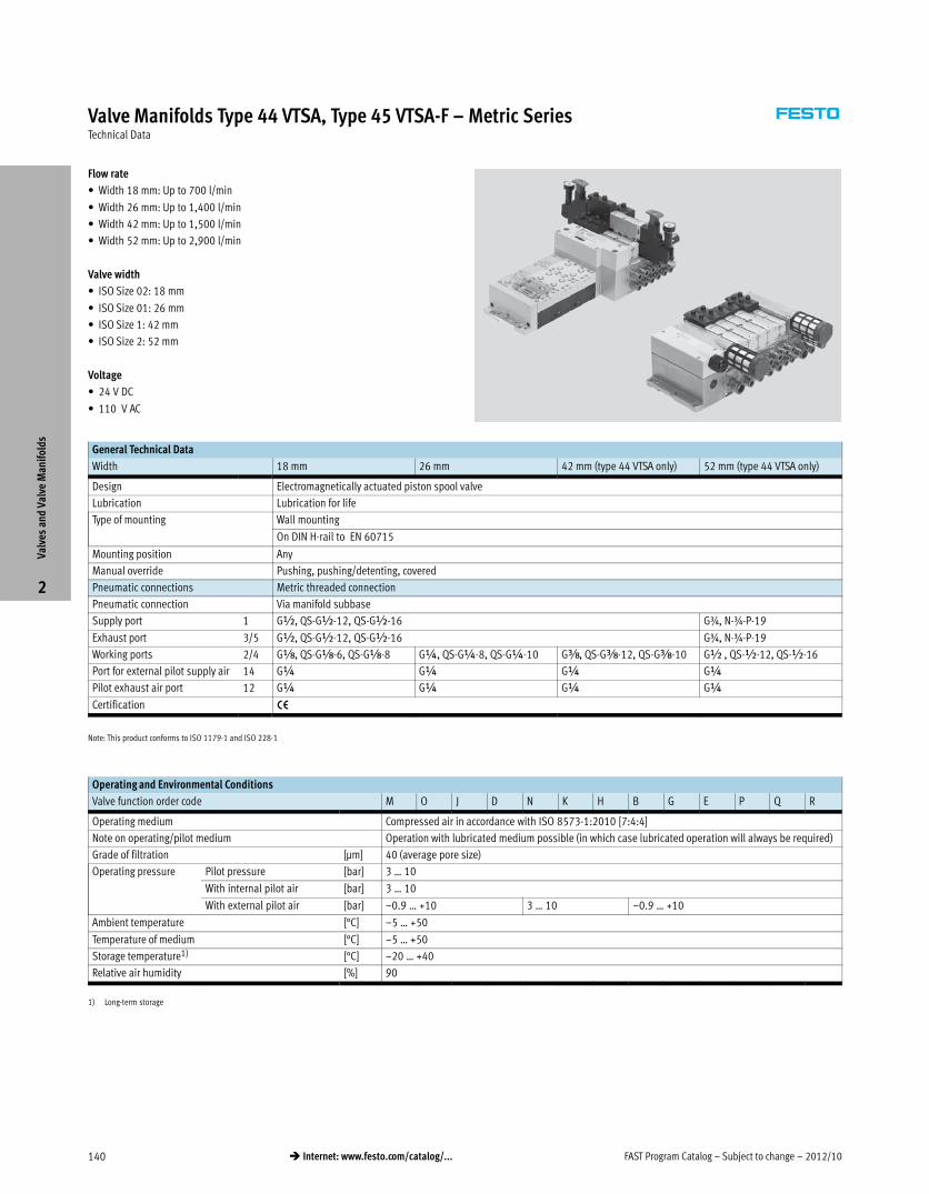
FAST Program Catalog – Subject to change – 2012/10140 � Internet: www.festo.com/catalog/...
Valve Manifolds Type 44 VTSA, Type 45 VTSA-F – Metric SeriesTechnical Data
Flow rate
� Width 18 mm: Up to 700 l/min
� Width 26 mm: Up to 1,400 l/min
� Width 42 mm: Up to 1,500 l/min
� Width 52 mm: Up to 2,900 l/min
Valve width
� ISO Size 02: 18 mm
� ISO Size 01: 26 mm
� ISO Size 1: 42 mm
� ISO Size 2: 52 mm
Voltage
� 24 V DC
� 110 V AC
General Technical Data
Width 18 mm 26 mm 42 mm (type 44 VTSA only) 52 mm (type 44 VTSA only)
Design Electromagnetically actuated piston spool valve
Lubrication Lubrication for life
Type of mounting Wall mounting
On DIN H-rail to EN 60715
Mounting position Any
Manual override Pushing, pushing/detenting, covered
Pneumatic connections Metric threaded connection
Pneumatic connection Via manifold subbase
Supply port 1 G½, QS-G½-12, QS-G½-16 G¾, N-¾-P-19
Exhaust port 3/5 G½, QS-G½-12, QS-G½-16 G¾, N-¾-P-19
Working ports 2/4 Gx, QS-Gx-6, QS-Gx-8 G¼, QS-G¼-8, QS-G¼-10 Gy, QS-Gy-12, QS-Gy-10 G½ , QS-½-12, QS-½-16
Port for external pilot supply air 14 G¼ G¼ G¼ G¼
Pilot exhaust air port 12 G¼ G¼ G¼ G¼
Certification —
Note: This product conforms to ISO 1179-1 and ISO 228-1
Operating and Environmental Conditions
Valve function order code M O J D N K H B G E P Q R
Operating medium Compressed air in accordance with ISO 8573-1:2010 [7:4:4]
Note on operating/pilot medium Operation with lubricated medium possible (in which case lubricated operation will always be required)
Grade of filtration [μm] 40 (average pore size)
Operating pressure Pilot pressure [bar] 3 … 10
With internal pilot air [bar] 3 … 10
With external pilot air [bar] –0.9 … +10 3 … 10 –0.9 … +10
Ambient temperature [°C] –5 … +50
Temperature of medium [°C] –5 … +50
Storage temperature1) [°C] –20 … +40
Relative air humidity [%] 90
1) Long-term storage
Valv
es a
nd V
alve
Man
ifol
ds
2
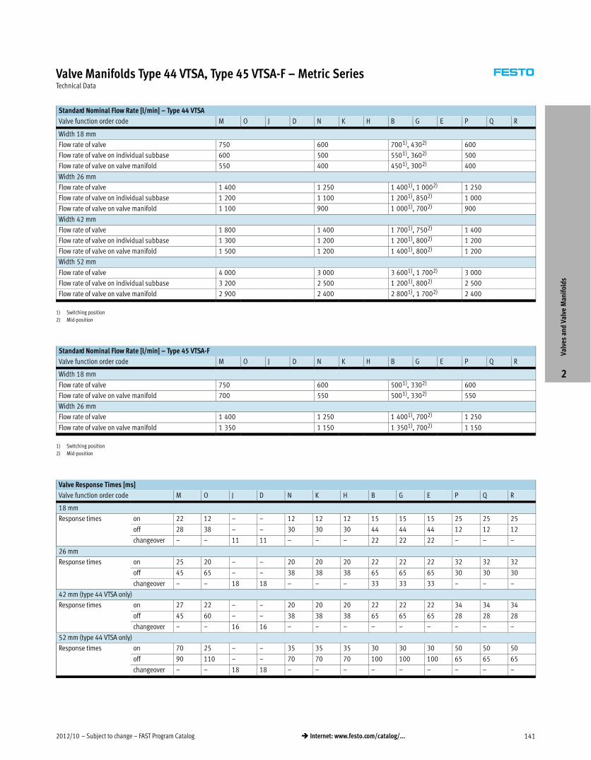
2012/10 – Subject to change – FAST Program Catalog 141� Internet: www.festo.com/catalog/...
Valve Manifolds Type 44 VTSA, Type 45 VTSA-F – Metric SeriesTechnical Data
Standard Nominal Flow Rate [l/min] – Type 44 VTSA
Valve function order code M O J D N K H B G E P Q R
Width 18 mm
Flow rate of valve 750 600 7001), 4302) 600
Flow rate of valve on individual subbase 600 500 5501), 3602) 500
Flow rate of valve on valve manifold 550 400 4501), 3002) 400
Width 26 mm
Flow rate of valve 1 400 1 250 1 4001), 1 0002) 1 250
Flow rate of valve on individual subbase 1 200 1 100 1 2001), 8502) 1 000
Flow rate of valve on valve manifold 1 100 900 1 0001), 7002) 900
Width 42 mm
Flow rate of valve 1 800 1 400 1 7001), 7502) 1 400
Flow rate of valve on individual subbase 1 300 1 200 1 2001), 8002) 1 200
Flow rate of valve on valve manifold 1 500 1 200 1 4001), 8002) 1 200
Width 52 mm
Flow rate of valve 4 000 3 000 3 6001), 1 7002) 3 000
Flow rate of valve on individual subbase 3 200 2 500 1 2001), 8002) 2 500
Flow rate of valve on valve manifold 2 900 2 400 2 8001), 1 7002) 2 400
1) Switching position
2) Mid-position
Standard Nominal Flow Rate [l/min] – Type 45 VTSA-F
Valve function order code M O J D N K H B G E P Q R
Width 18 mm
Flow rate of valve 750 600 5001), 3302) 600
Flow rate of valve on valve manifold 700 550 5001), 3302) 550
Width 26 mm
Flow rate of valve 1 400 1 250 1 4001), 7002) 1 250
Flow rate of valve on valve manifold 1 350 1 150 1 3501), 7002) 1 150
1) Switching position
2) Mid-position
Valve Response Times [ms]
Valve function order code M O J D N K H B G E P Q R
18 mm
Response times on 22 12 – – 12 12 12 15 15 15 25 25 25
off 28 38 – – 30 30 30 44 44 44 12 12 12
changeover – – 11 11 – – – 22 22 22 – – –
26 mm
Response times on 25 20 – – 20 20 20 22 22 22 32 32 32
off 45 65 – – 38 38 38 65 65 65 30 30 30
changeover – – 18 18 – – – 33 33 33 – – –
42 mm (type 44 VTSA only)
Response times on 27 22 – – 20 20 20 22 22 22 34 34 34
off 45 60 – – 38 38 38 65 65 65 28 28 28
changeover – – 16 16 – – – – – – – – –
52 mm (type 44 VTSA only)
Response times on 70 25 – – 35 35 35 30 30 30 50 50 50
off 90 110 – – 70 70 70 100 100 100 65 65 65
changeover – – 18 18 – – – – – – – – –
Valv
es a
nd V
alve
Man
ifol
ds
2
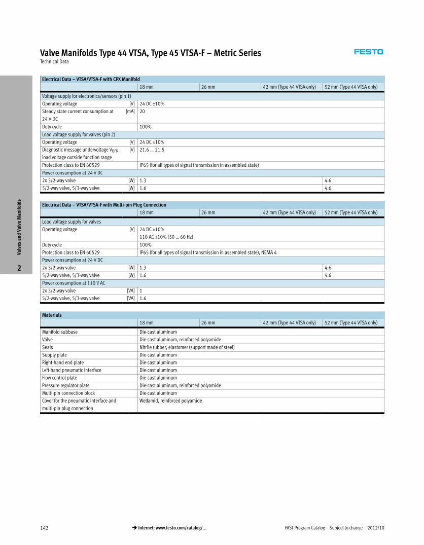
FAST Program Catalog – Subject to change – 2012/10142 � Internet: www.festo.com/catalog/...
Valve Manifolds Type 44 VTSA, Type 45 VTSA-F – Metric SeriesTechnical Data
Electrical Data – VTSA/VTSA-F with CPX Manifold
18 mm 26 mm 42 mm (Type 44 VTSA only) 52 mm (Type 44 VTSA only)
Voltage supply for electronics/sensors (pin 1)
Operating voltage [V] 24 DC ±10%
Steady state current consumption at
24 V DC
[mA] 20
Duty cycle 100%
Load voltage supply for valves (pin 2)
Operating voltage [V] 24 DC ±10%
Diagnostic message undervoltage VOFF,
load voltage outside function range
[V] 21.6 … 21.5
Protection class to EN 60529 IP65 (for all types of signal transmission in assembled state)
Power consumption at 24 V DC
2x 3/2-way valve [W] 1.3 4.6
5/2-way valve, 5/3-way valve [W] 1.6 4.6
Electrical Data – VTSA/VTSA-F with Multi-pin Plug Connection
18 mm 26 mm 42 mm (Type 44 VTSA only) 52 mm (Type 44 VTSA only)
Load voltage supply for valves
Operating voltage [V] 24 DC ±10%
110 AC ±10% (50 … 60 Hz)
Duty cycle 100%
Protection class to EN 60529 IP65 (for all types of signal transmission in assembled state), NEMA 4
Power consumption at 24 V DC
2x 3/2-way valve [W] 1.3 4.6
5/2-way valve, 5/3-way valve [W] 1.6 4.6
Power consumption at 110 V AC
2x 3/2-way valve [VA] 1
5/2-way valve, 5/3-way valve [VA] 1.6
Materials
18 mm 26 mm 42 mm (Type 44 VTSA only) 52 mm (Type 44 VTSA only)
Manifold subbase Die-cast aluminum
Valve Die-cast aluminum, reinforced polyamide
Seals Nitrile rubber, elastomer (support made of steel)
Supply plate Die-cast aluminum
Right-hand end plate Die-cast aluminum
Left-hand pneumatic interface Die-cast aluminum
Flow control plate Die-cast aluminum
Pressure regulator plate Die-cast aluminum, reinforced polyamide
Multi-pin connection block Die-cast aluminum
Cover for the pneumatic interface and
multi-pin plug connection
Wellamid, reinforced polyamide
Valv
es a
nd V
alve
Man
ifol
ds
2
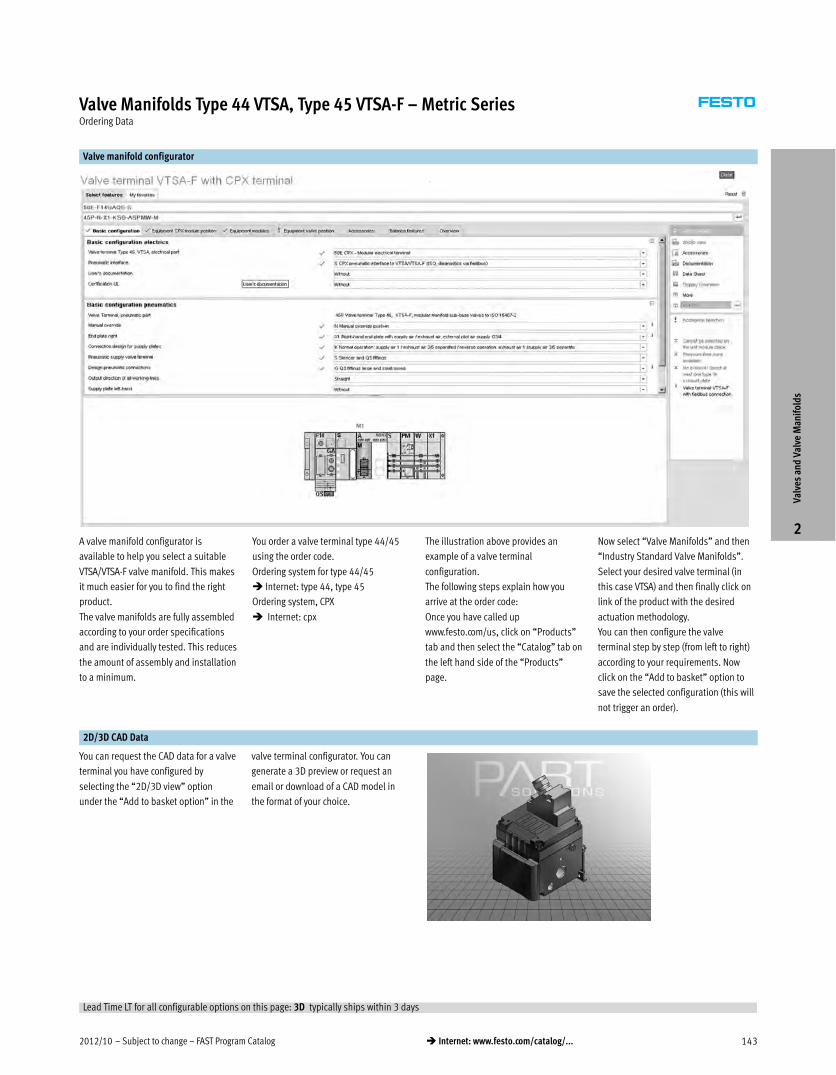
2012/10 – Subject to change – FAST Program Catalog 143� Internet: www.festo.com/catalog/...
Valve Manifolds Type 44 VTSA, Type 45 VTSA-F – Metric SeriesOrdering Data
Valve manifold configurator
A valve manifold configurator is
available to help you select a suitable
VTSA/VTSA-F valve manifold. This makes
it much easier for you to find the right
product.
The valve manifolds are fully assembled
according to your order specifications
and are individually tested. This reduces
the amount of assembly and installation
to a minimum.
You order a valve terminal type 44/45
using the order code.
Ordering system for type 44/45
� Internet: type 44, type 45
Ordering system, CPX
� Internet: cpx
The illustration above provides an
example of a valve terminal
configuration.
The following steps explain how you
arrive at the order code:
Once you have called up
www.festo.com/us, click on “Products”
tab and then select the “Catalog” tab on
the left hand side of the “Products”
page.
Now select “Valve Manifolds” and then
“Industry Standard Valve Manifolds”.
Select your desired valve terminal (in
this case VTSA) and then finally click on
link of the product with the desired
actuation methodology.
You can then configure the valve
terminal step by step (from left to right)
according to your requirements. Now
click on the “Add to basket” option to
save the selected configuration (this will
not trigger an order).
2D/3D CAD Data
You can request the CAD data for a valve
terminal you have configured by
selecting the “2D/3D view” option
under the “Add to basket option” in the
valve terminal configurator. You can
generate a 3D preview or request an
email or download of a CAD model in
the format of your choice.Va
lves
and
Val
ve M
anif
olds
2
Lead Time LT for all configurable options on this page: 3D typically ships within 3 days
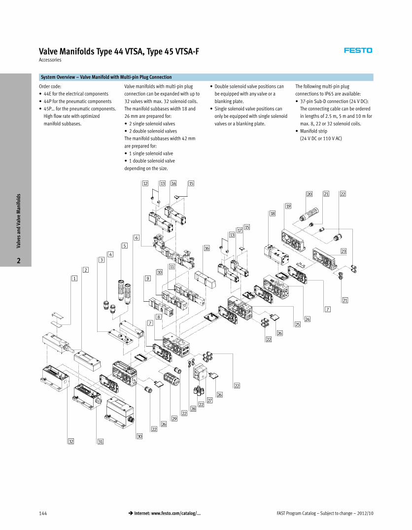
FAST Program Catalog – Subject to change – 2012/10144 � Internet: www.festo.com/catalog/...
Valve Manifolds Type 44 VTSA, Type 45 VTSA-FAccessories
System Overview – Valve Manifold with Multi-pin Plug Connection
Order code:
� 44E for the electrical components
� 44P for the pneumatic components
� 45P… for the pneumatic components.
High flow rate with optimized
manifold subbases.
Valve manifolds with multi-pin plug
connection can be expanded with up to
32 valves with max. 32 solenoid coils.
The manifold subbases width 18 and
26 mm are prepared for:
� 2 single solenoid valves
� 2 double solenoid valves
The manifold subbases width 42 mm
are prepared for:
� 1 single solenoid valve
� 1 double solenoid valve
depending on the size.
� Double solenoid valve positions can
be equipped with any valve or a
blanking plate.
� Single solenoid valve positions can
only be equipped with single solenoid
valves or a blanking plate.
The following multi-pin plug
connections to IP65 are available:
� 37-pin Sub-D connection (24 V DC):
The connecting cable can be ordered
in lengths of 2.5 m, 5 m and 10 m for
max. 8, 22 or 32 solenoid coils.
� Manifold strip
(24 V DC or 110 V AC)
2
1
aC
34
5
6
aB aEaD
78
9aJ
aA
aF
aCaG
aE
aH
aI
bJ bA bB
bC
bA
7
bD
bF
bE
bB
bB
bF
bB
bG
bHbB
bFbB
bI
cJcAcB
Valv
es a
nd V
alve
Man
ifol
ds
2
2012/10 – Subject to change – FAST Program Catalog 145� Internet: www.festo.com/catalog/...
Valve Manifolds Type 44 VTSA, Type 45 VTSA-FAccessories
System Overview – Valve Manifold with Multi-pin Plug Connection
Brief description
1 Inscription labels Large, for multi-pin plug connection
2 Multi-core cable –
3 Exhaust plate Ports 3 and 5 separated
4 Fittings For supply plate
5 Silencer For supply plate
6 Exhaust port cover For ducted exhaust air (ports 3 and 5
combined)
7 Duct separation/seal –
8 Manifold subbase For valves with a width of 26 mm
9 Flow control plate –
aJ Vertical supply plate –
aA Vertical shut-off plate –
aB Pressure regulator plate –
aC Cover cap For manual override, pushing, covered
aD Valve Width 26 mm
aE Inscription label holder For valve
aF Blanking plate For unused valve position (vacant position)
aG Valve Width 18 mm
Brief description
aH Valve Width 42 mm (type 44 only)
aI Right-hand end plate –
bJ Silencer For end plate
bA Blanking plugs –
bB Fittings –
bC End plate with pilot air selector –
bD Manifold subbase For valves with a width of 42 mm (type 44
only)
bE Manifold subbase For valves with a width of 18 mm
bF Inscription label holder For supply plate, subbase, 90°
connection plate
bG 90° connection plate –
bH Seals –
bI Silencer –
cJ Supply plate –
cA Multi-pin plug connection Via manifold strip (CageClamp) 24 V DC or110 V AC
cB Multi-pin plug connection With multi-core cable 24 V DC
Valv
es a
nd V
alve
Man
ifol
ds
2
FAST Program Catalog – Subject to change – 2012/10146 � Internet: www.festo.com/catalog/...
Valve Manifolds Type 44 VTSA, Type 45 VTSA-FSystem Overview
System Overview – Valve Manifold with Fieldbus Connection, Control Block (Electrical Peripherals CPX)
Order code:
� 50E-… for the electrical peripherals
� 44P for the pneumatic components
� 45P… for the pneumatic components.
High flow rate with optimized
manifold subbases.
Valve manifolds with fieldbus interface
can be expanded with up to 32 valves
with max. 32 solenoid coils.
Each valve position can be fitted with
any valve or a blanking plate.
The rules for CPX apply to the
equipment that can be used in
combination with the electrical
peripherals CPX.
In general:
� Max. 10 electrical modules
� Digital inputs/outputs
� Analog inputs/outputs
� Parameterisation of inputs and
outputs
� Integrated feature-rich diagnostic
system
� Preventive maintenance concepts
1
aB
23
4
5
aA aDaC
67
89
aJ
aE
aBaF
aD
aG
aH
aI bJ bA
bB
bJ
6
bC
bE
bD
bA
bA
bE
bA
bF
bGbA
bFbA
bH
bI6cJcA
Valv
es a
nd V
alve
Man
ifol
ds
2
2012/10 – Subject to change – FAST Program Catalog 147� Internet: www.festo.com/catalog/...
Valve Manifolds Type 44 VTSA, Type 45 VTSA-FSystem Overview
System Overview – Valve Manifold with Fieldbus Connection, Control Block (Electrical Peripherals CPX)
Brief description
1 Inscription labels Large, for pneumatic interface CPX
2 Exhaust plate Ports 3 and 5 separated
3 Fittings For supply plate
4 Silencer For supply plate
5 Exhaust port cover For ducted exhaust air (ports 3 and 5
combined)
6 Duct separation/seal –
7 Manifold subbase For valves with a width of 26 mm
8 Flow control plate –
9 Vertical supply plate –
aJ Vertical shut-off plate –
aA Pressure regulator plate –
aB Cover cap For manual override, pushing, covered
aC Valve Width 26 mm
aD Inscription label holder For valve
aE Blanking plate For unused valve position (vacant position)
aF Valve Width 18 mm
Brief description
aG Valve Width 42 mm (type 44 only)
aH Right-hand end plate –
aI Silencer For end plate
bJ Blanking plugs –
bA Fittings –
bB End plate with pilot air selector –
bC Manifold subbase For valves with a width of 42 mm (type 44
only)
bD Manifold subbase For valves with a width of 18 mm
bE Inscription label holder For supply plate/subbase/90° connection
plate
bF 90° connection plate –
bG Seals –
bH Silencer –
bI Supply plate –
cJ Pneumatic interface –
cA Fieldbus interface –
Valv
es a
nd V
alve
Man
ifol
ds
2
ISO 9001
ISO 14001
CertifiedCompany
9001
:CER
TC5-
1624
8-20
06-A
Q-E
SN-T
GA
1400
1:CE
RTC5
-162
48A-
2006
-AQ
-ESN
-TG
ASupporting Advanced Automation… As No One Else Can!Festo is a leading global manufacturer of pneumatic and electromechanical systems, components and controls for industrial automation, with more than 12,000 employees in 56 national headquarters serving more than 180 countries. For more than 80 years, Festo has continuously elevated the state of manufacturing with innovations and optimized motion control solutions that deliver higher performing, more profitable automated manufacturing and processing equipment. Our dedication to the advancement of automation extends beyond technology to the education and development of current and future automation and robotics designers with simulation tools, teaching programs, and on-site services.
Quality Assurance, ISO 9001 and ISO 14001 CertificationsFesto Corporation is committed to supply all Festo products and services that will meet or exceed our customers’ requirements in product quality, delivery, customer service and satisfaction.
To meet this commitment, we strive to ensure a consistent, integrated, and systematic approach to management that will meet or exceed the requirements of the ISO 9001 standard for Quality Management and the ISO 14001 standard for Environmental Management.
© Copyright 2008, Festo Corporation. While every effort is made to ensure that all dimensions and specifications are correct, Festo cannot guarantee that publications are completely free of any error, in particular typing or printing errors. Accordingly, Festo cannot be held responsible for the same. For Liability and Warranty conditions, refer to our “Terms and Conditions of Sale”, available from your local Festo office. All rights reserved. No part of this publication may be reproduced, distributed, or transmitted in any form or by any means, electronic, mechanical, photocopying or otherwise, without the prior written permission of Festo. All technical data subject to change according to technical update.
Product Range and Company Overview
A Complete Suite and Company Overview
The Broadest Range of Automation Components
Our experienced engineers provide complete support at every stage of your development process, including: conceptualization,analysis, engineering, design, assembly, documentation, validation, and production.
With a comprehensive line of more than 30,000 automation components, Festo is capable of solving the most complexautomation requirements.
Custom Automation ComponentsComplete custom engineered solutions
Custom Control CabinetsComprehensive engineering supportand on-site services
Complete SystemsShipment, stocking and storage services
ElectromechanicalElectromechanical actuators, motors, controllers & drivers
PneumaticsPneumatic linear and rotary actuators,valves, and air supply
PLCs and I/O DevicesPLC’s, operator interfaces, sensorsand I/O devices
Printed on recycled paper at New Horizon Graphic, Inc., FSC certified as an environmental friendly printing plant.
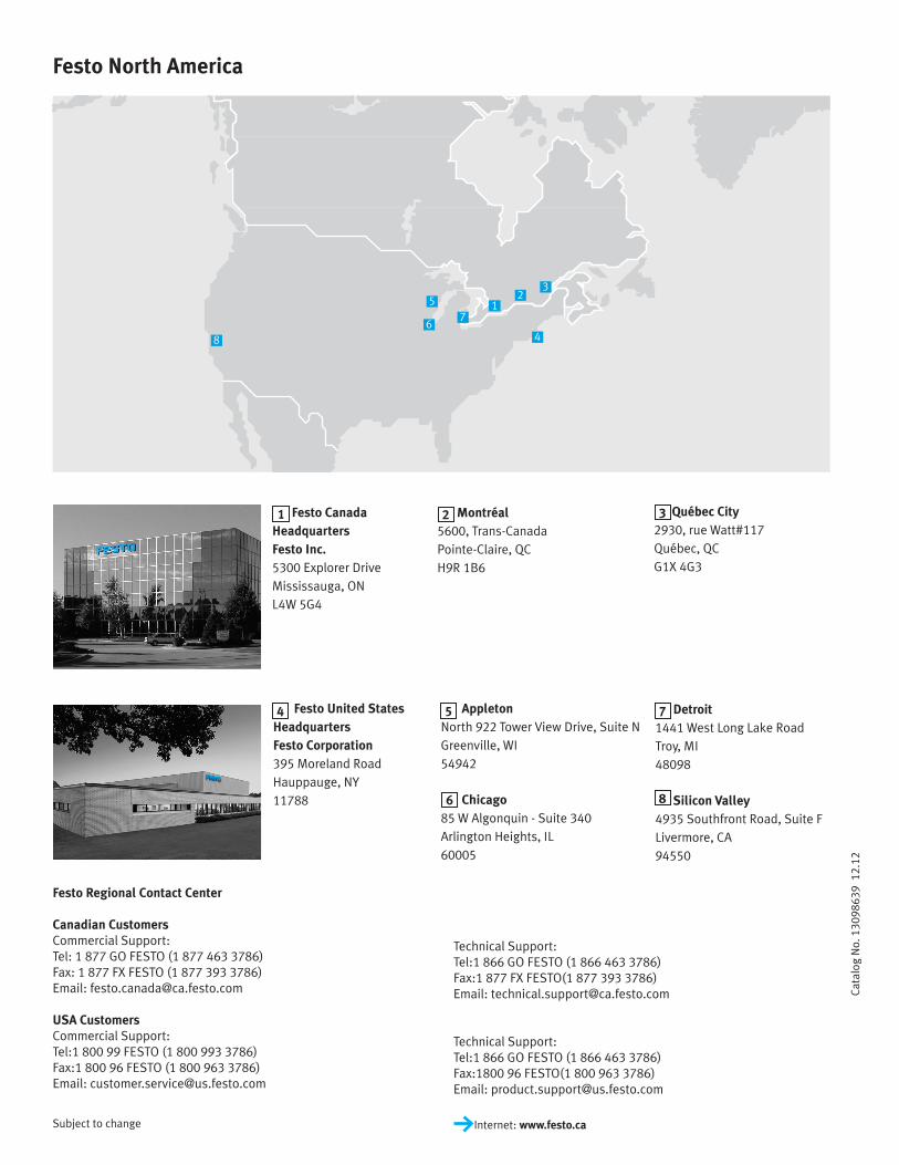
Festo North America
Festo Regional Contact Center
Canadian CustomersCommercial Support:Tel: 1 877 GO FESTO (1 877 463 3786)Fax: 1 877 FX FESTO (1 877 393 3786)Email: [email protected]
USA CustomersCommercial Support:Tel:1 800 99 FESTO (1 800 993 3786)Fax:1 800 96 FESTO (1 800 963 3786)Email: [email protected]
Technical Support:Tel:1 866 GO FESTO (1 866 463 3786)Fax:1 877 FX FESTO(1 877 393 3786)Email: [email protected]
Technical Support:Tel:1 866 GO FESTO (1 866 463 3786)Fax:1800 96 FESTO(1 800 963 3786)Email: [email protected]
Cata
log
No.
130
9863
9 1
2.12
Festo Canada HeadquartersFesto Inc.5300 Explorer DriveMississauga, ONL4W 5G4
Montréal5600, Trans-CanadaPointe-Claire, QCH9R 1B6
Québec City2930, rue Watt#117Québec, QCG1X 4G3
Festo United StatesHeadquarters Festo Corporation395 Moreland RoadHauppauge, NY11788
Detroit1441 West Long Lake RoadTroy, MI48098
Silicon Valley4935 Southfront Road, Suite FLivermore, CA94550
AppletonNorth 922 Tower View Drive, Suite NGreenville, WI54942
Chicago85 W Algonquin - Suite 340Arlington Heights, IL60005
6
1 2 3
4 5 7
8
Subject to change Internet: www.festo.ca