Embed Size (px)
Citation preview
FAST™ Program 2010Festo Assured Shipping Time
A complete line of automation components available when you need them!
FAST™ Program 2010Festo Assured Shipping Time
A complete line of automation componentsavailable when you need them!
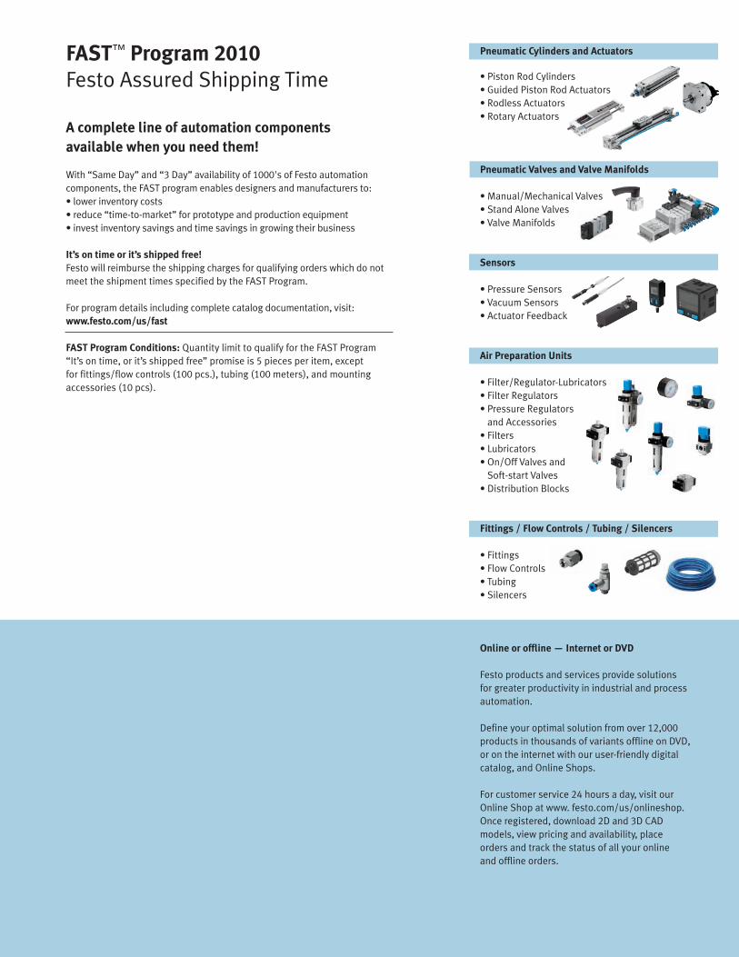
With “Same Day” and “3 Day” availability of 1000's of Festo automationcomponents, the FAST program enables designers and manufacturers to:• lower inventory costs• reduce “time-to-market” for prototype and production equipment• invest inventory savings and time savings in growing their business
It’s on time or it’s shipped free!Festo will reimburse the shipping charges for qualifying orders which do notmeet the shipment times specified by the FAST Program.
For program details including complete catalog documentation, visit:www.festo.com/us/fast
FAST Program Conditions: Quantity limit to qualify for the FAST Program“It’s on time, or it’s shipped free” promise is 5 pieces per item, exceptfor fittings/flow controls (100 pcs.), tubing (100 meters), and mountingaccessories (10 pcs).
Pneumatic Cylinders and Actuators
• Piston Rod Cylinders• Guided Piston Rod Actuators• Rodless Actuators• Rotary Actuators
Pneumatic Valves and Valve Manifolds
• Manual/Mechanical Valves• Stand Alone Valves• Valve Manifolds
Sensors
• Pressure Sensors• Vacuum Sensors• Actuator Feedback
Air Preparation Units
• Filter/Regulator-Lubricators• Filter Regulators• Pressure Regulators
and Accessories• Filters• Lubricators• On/Off Valves and
Soft-start Valves• Distribution Blocks
Fittings / Flow Controls / Tubing / Silencers
• Fittings• Flow Controls• Tubing• Silencers
Online or offline — Internet or DVD
Festo products and services provide solutionsfor greater productivity in industrial and processautomation.
Define your optimal solution from over 12,000products in thousands of variants offline on DVD,or on the internet with our user-friendly digitalcatalog, and Online Shops.
For customer service 24 hours a day, visit ourOnline Shop at www. festo.com/us/onlineshop.Once registered, download 2D and 3D CADmodels, view pricing and availability, placeorders and track the status of all your onlineand offline orders.
2010/03 – Subject to change – FAST Program Catalog 105
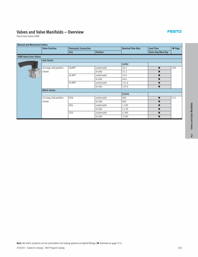
Valves and Valve Manifolds – OverviewHand Lever Valves VHER
Manual and Mechanical Valves
Valve Function Pneumatic Connection Nominal Flow Rate Lead Time � Page
Size Position Same Day/Next Day
VHER Hand Lever Valves
Inch Series
[scfm]
4/3-way, mid-position x NPT underneath 28.2 � 109/3 y, p
closed
x
at side 21.2 �
9
¼ NPT underneath 53.0 �¼
at side 40.6 �
½ NPT underneath 151.8 �½
at side 123.6 �
Metric Series
[l/min]
4/3-way, mid-position Gx underneath 800 � 115/3 y, p
closed
x
at side 600 �
5
G¼ underneath 1,500 �¼
at side 1,150 �
G½ underneath 4,300 �½
at side 3,500 �
ValvesandValve
Manifolds
2
Note: All metric products can be used within inch tubing systems via hybrid fittings (� Overview on page 271)

FAST Program Catalog – Subject to change – 2010/03106
Valves and Valve Manifolds – OverviewStand Alone Valves and Manifold Blocks CPE
Stand-alone Valves
Valve Function Nominal Flow Rate Valve Width Pneumatic Connection Lead Time � Page
[bar] [mm] Same Day/Next Day
CPE Solenoid Valves, Compact Performance
Metric Series
3/2-way Normally open 190 10 M5 � 1213/ y y p
Normally closed 900 14 Gx �
5/2-way, single-solenoid 180 10 M5 �5/ y, g
800 14 Gx �
5/2-way, double-solenoid 180 10 M5 �5/ y,
800 14 Gx �
5/3-way Normally closed
Normally exhausted
180 10 M5�
y
Normally pressurized 700 … 750 14 Gx�
Manifold Blocks
Valve Function Nominal Flow Rate Valve Width Pneumatic Connection Number of Valves Lead Time � Page
1, 3, 5 2, 4 3 Days
CPE Solenoid Valves, Compact Performance
Inch Series
[scfm] [in]
5/2-way, single-solenoid 6.4 0.39 ¼ NPT M5 2, 4, 6, 8, 10 � 1275/ y, g
28.2 0.55 y NPT Gx
, , , ,
�
7
5/2-way, double-solenoid 6.4 0.39 ¼ NPT M5 2, 4, 6, 8, 10 �5/ y,
28.2 0.55 y NPT Gx
, , , ,
�
5/3-way Normally closed
Normally exhausted
6.4 0.39 ¼ NPT M5 2, 4, 6, 8, 10�
y
Normally pressurized 24.7 … 26.5 0.55 y NPT Gx�
Metric Series
[l/min] [mm]
5/2-way, single-solenoid 180 10 G¼ M5 2, 4, 6, 8, 10 � 1275/ y, g
800 14 Gy Gx
, , , ,
�
7
5/2-way, double-solenoid 180 10 G¼ M5 2, 4, 6, 8, 10 �5/ y,
800 14 Gy Gx
, , , ,
�
5/3-way Normally closed
Normally exhausted
180 10 G¼ M5 2, 4, 6, 8, 10�
y
Normally pressurized 700 … 750 14 Gy Gx�
ValvesandValve
Manifolds
2
Note: All metric products can be used within inch tubing systems via hybrid fittings (� Overview on page 271)
2010/03 – Subject to change – FAST Program Catalog 107
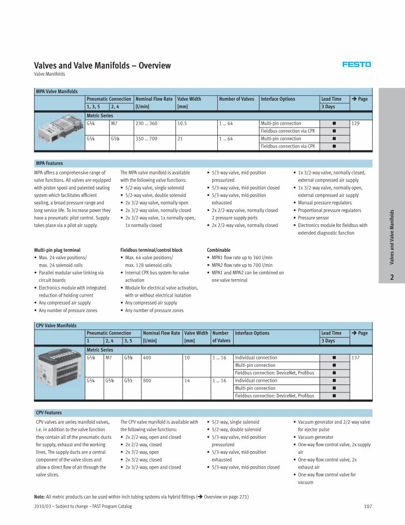
Valves and Valve Manifolds – OverviewValve Manifolds
MPA Valve Manifolds
Pneumatic Connection Nominal Flow Rate Valve Width Number of Valves Interface Options Lead Time � Page
1, 3, 5 2, 4 [l/min] [mm] 3 Days
Metric Series
G¼ M7 230 … 360 10.5 1 … 64 Multi-pin connection � 129¼ 7 3 3 5
Fieldbus connection via CPX �
9
G¼ Gx 350 … 700 21 1 … 64 Multi-pin connection �¼ x 35 7
Fieldbus connection via CPX �
MPA Features
MPA offers a comprehensive range of
valve functions. All valves are equipped
with piston spool and patented sealing
system which facilitates efficient
sealing, a broad pressure range and
long service life. To increase power they
have a pneumatic pilot control. Supply
takes place via a pilot air supply.
The MPA valve manifold is available
with the following valve functions:
• 5/2-way valve, single solenoid
• 5/2-way valve, double solenoid
• 2x 3/2-way valve, normally open
• 2x 3/2-way valve, normally closed
• 2x 3/2-way valve, 1x normally open,
1x normally closed
• 5/3-way valve, mid-position
pressurized
• 5/3-way valve, mid-position closed
• 5/3-way valve, mid-position
exhausted
• 2x 2/2-way valve, normally closed
2 pressure supply ports
• 2x 2/2-way valve, normally closed
• 1x 3/2-way valve, normally closed,
external compressed air supply
• 1x 3/2-way valve, normally open,
external compressed air supply
• Manual pressure regulators
• Proportional pressure regulators
• Pressure sensor
• Electronics module for fieldbus with
extended diagnostic function
Multi-pin plug terminal
• Max. 24 valve positions/
max. 24 solenoid coils
• Parallel modular valve linking via
circuit boards
• Electronics module with integrated
reduction of holding current
• Any compressed air supply
• Any number of pressure zones
Fieldbus terminal/control block
• Max. 64 valve positions/
max. 128 solenoid coils
• Internal CPX bus system for valve
activation
• Module for electrical valve activation,
with or without electrical isolation
• Any compressed air supply
• Any number of pressure zones
Combinable
• MPA1 flow rate up to 360 l/min
• MPA2 flow rate up to 700 l/min
• MPA1 and MPA2 can be combined on
one valve terminal
CPV Valve Manifolds
Pneumatic Connection Nominal Flow Rate Valve Width Number Interface Options Lead Time � Page
1 2, 4 3, 5 [l/min] [mm] of Valves 3 Days
Metric Series
Gx M7 Gy 400 10 1 … 16 Individual connection � 137x 7 y
Multi-pin connection �
37
Fieldbus connection: DeviceNet, Profibus �
G¼ Gx G½ 800 14 1 … 16 Individual connection �¼ x ½
Multi-pin connection �
Fieldbus connection: DeviceNet, Profibus �
CPV Features
CPV valves are series manifold valves,
i.e. in addition to the valve function
they contain all of the pneumatic ducts
for supply, exhaust and the working
lines. The supply ducts are a central
component of the valve slices and
allow a direct flow of air through the
valve slices.
The CPV valve manifold is available with
the following valve functions:
• 2x 2/2-way, open and closed
• 2x 2/2-way, closed
• 2x 3/2-way, open
• 2x 3/2-way, closed
• 2x 3/2-way, open and closed
• 5/2-way, single solenoid
• 5/2-way, double solenoid
• 5/3-way valve, mid-position
pressurized
• 5/3-way valve, mid-position
exhausted
• 5/3-way valve, mid-position closed
• Vacuum generator and 2/2-way valve
for ejector pulse
• Vacuum generator
• One-way flow control valve, 2x supply
air
• One-way flow control valve, 2x
exhaust air
• One-way flow control valve for
vacuum
ValvesandValve
Manifolds
2
Note: All metric products can be used within inch tubing systems via hybrid fittings (� Overview on page 271)
FAST Program Catalog – Subject to change – 2010/03108
Valves and Valve Manifolds – OverviewValve Manifolds
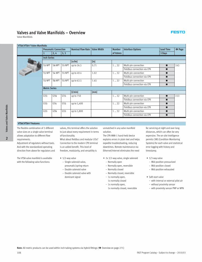
VTSA/VTSA-F Valve Manifolds
Pneumatic Connection Nominal Flow Rate Valve Width Number Interface Options Lead Time � Page
1 2, 4 3, 5 of Valves 3 Days
Inch Series
[scfm] [in]
½ NPT x NPT ½ NPT up to 26.5 0.71 1 … 32 Multi-pin connection � 145½ x ½ p 5 7 3
Fieldbus connection via CPX �
5
½ NPT ¼ NPT ½ NPT up to 49.4 1.02 1 … 32 Multi-pin connection �½ ¼ ½ p 9 3
Fieldbus connection via CPX �
½ NPT y NPT ½ NPT up to 63.5 1.65 1 … 32 Multi-pin connection �½ y ½ p 3 5 5 3
Fieldbus connection via CPX �
Metric Series
[l/min] [mm]
G½ Gx G½ up to 750 1 … 32 Multi-pin connection � 153½ x ½ p 75 3
Fieldbus connection via CPX �
53
G½ G¼ G½ up to 1,400 1 … 32 Multi-pin connection �½ ¼ ½ p , 3
Fieldbus connection via CPX �
G½ Gy G½ up to 1,800 1 … 32 Multi-pin connection �½ y ½ p , 3
Fieldbus connection via CPX �
VTSA/VTSA-F Features
The flexible combination of 3 different
valve sizes on a single valve terminal
allows adaptation to different flow
requirements.
Adjustment of regulators without tools.
And with the standardized operating
direction from above for regulators and
valves, this terminal offers the solution
to just about every requirement in terms
of functionality.
What about fieldbus and modular I/Os?
Connection to the modern CPX terminal
is an added benefit. This level of
freedom, modularity, and versatility is
unmatched in any valve manifold
solution.
The CPX-MMI-1 hand-held device
explains errors in plain text and helps
expedite troubleshooting, reducing
downtimes. Remote maintenance via
Ethernet/Internet eliminates the need
for servicing at night and over long
distances, which can often be very
expensive. The on-site intelligence
permits CMS (Condition Monitoring
Systems) for each valve and statistical
error logging with history and
timestamp.
The VTSA valve manifold is available
with the following valve functions:
• 5/2-way valve
– Single solenoid valve,
pneumatic/spring return
– Double solenoid valve
– Double solenoid valve with
dominant signal
• 2x 3/2-way valve, single solenoid
– Normally open
– Normally open, reversible
– Normally closed
– Normally closed, reversible
– 1x normally open,
1x normally closed
– 1x normally open,
1x normally closed, reversible
• 5/3-way valve
– Mid-position pressurized
– Mid-position closed
– Mid-position exhausted
• Soft-start valve
– with internal or external pilot air
– without proximity sensor
– with proximity sensor PNP or NPN
ValvesandValve
Manifolds
2
Note: All metric products can be used within inch tubing systems via hybrid fittings (� Overview on page 271)

2010/03 – Subject to change – FAST Program Catalog 109
Hand Lever Valves VHER – Inch SeriesOverview
Hand lever valves VHER are used to manually control the motion of
cylinders within the stroke range.
• 4/3-way valve, mid-position closed
• Flow rate: 21.2 … 151.8 scfm
• Operating pressure: –14.0 … +150 psi
• Pneumatic connection: xNPT,¼ NPT,½ NPT
Product Range Overview
Valve function Pneumatic connection Nominal diameter Flow rate
Position Size [in] [scfm]
4/3-way valve, mid-position underneath x NPT 0.24 28.2/3 y , p
closed ¼ NPT 0.31 53.0
½ NPT 0.47 151.8
at side x NPT 0.24 21.2
¼ NPT 0.31 40.6
½ NPT 0.47 123.6
Features Contents
Versatile Practical Technical Data � 110
• 4/3-way valve: • With these valves it is possible to • In mid-position closed, the drive Ordering Data � 110/ y
mid-position closed
p
stop single-acting cylinders
p ,
piston moves until the forces are Accessories � 112p
P ti ti
p g g y
(3/3 l ) d bl ti
p
b l d• Pneumatic connection
x NPT ¼ NPT ½ NPT
(3/3-way valve) or double-acting
li d (4/3 l ) ithi th
balanced.
x NPT,¼ NPT,½ NPT
• 3/3-way valve:
VHER valves an be used as 3/3-way
valves by sealing port 2
cylinders (4/3-way valve) within the
stroke range.ValvesandValve
Manifolds
2
Detailed product information� www.festo.com/catalog/vher
FAST Program Catalog – Subject to change – 2010/03110
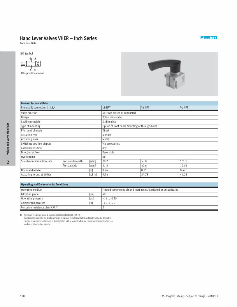
Hand Lever Valves VHER – Inch SeriesTechnical Data
ISO Symbol
Mid-position closed
General Technical Data
Pneumatic connection 1,2,3,4 x NPT ¼ NPT ½ NPT
Valve function 4/3-way, closed or exhausted
Design Rotary slide valve
Sealing principle Sliding disk
Type of mounting Option of front panel mounting or through-holes
Pilot control mode Direct
Actuation type Manual
Actuating lever Metal
Switching position display Via accessories
Assembly position Any
Direction of flow Reversible
Overlapping No
Standard nominal flow rate Ports underneath [scfm] 28.2 53.0 151.8
Ports at side [scfm] 21.2 40.6 123.6
Nominal diameter [in] 0.24 0.31 0.47
Actuating torque at 10 bar [lbf-in] 9.74 24.78 44.25
Operating and Environmental Conditions
Operating medium Filtered compressed air and inert gases, lubricated or unlubricated
Filtration grade [µm] 40
Operating pressure [psi] –14 … +150
Ambient temperature [°F] –4 … +176
Corrosion resistance class CRC1) 2*
1) Corrosion resistance class 2 according to Festo standard 940 070
Components requiring moderate corrosion resistance. Externally visible parts with primarily decorative
surface requirements which are in direct contact with a normal industrial environment or media such as
coolants or lubricating agents.
ValvesandValve
Manifolds
2

2010/03 – Subject to change – FAST Program Catalog 111
Hand Lever Valves VHER – Inch SeriesTechnical Data, Ordering Data
Sectional View
Ports underneath Ports at side
1
1
Materials
1 Housing Die-cast aluminum
– Seals Nitrile rubber
– Contains PWIS (paint wetting impairment substances)
– Free of copper and PTFE
Ordering Data
Valve function Pneumatic connection Weight Type LT
Position Size [lb]
Mid-position closed Underneath Á NPT 0.44 VHER-AH-M04C-N18-UD 1Wp
¼ NPT 1.02 VHER-AH-M04C-N14-UD 1W
½ NPT 1.72 VHER-AH-M04C-N12-UD 1W
Side Á NPT 0.52 VHER-AH-M04C-N18-LD 1W
¼ NPT 1.12 VHER-AH-M04C-N14-LD 1W
½ NPT 2.02 VHER-AH-M04C-N12-LD 1W
LT = Lead time 1D typically ships same day/next day 1W typically ships within 1 week
ValvesandValve
Manifolds
2
FAST Program Catalog – Subject to change – 2010/03112
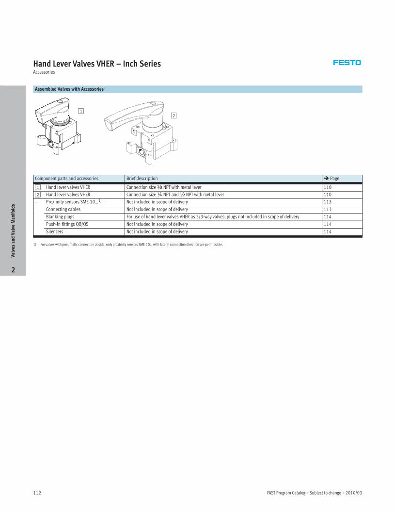
Hand Lever Valves VHER – Inch SeriesAccessories
Assembled Valves with Accessories
12
Component parts and accessories Brief description � Page
1 Hand lever valves VHER Connection sizex NPT with metal lever 110
2 Hand lever valves VHER Connection size¼ NPT and½ NPT with metal lever 110
– Proximity sensors SME-10…1) Not included in scope of delivery 113
Connecting cables Not included in scope of delivery 113
Blanking plugs For use of hand lever valves VHER as 3/3-way valves; plugs not included in scope of delivery 114
Push-in fittings QB/QS Not included in scope of delivery 114
Silencers Not included in scope of delivery 114
1) For valves with pneumatic connection at side, only proximity sensors SME-10… with lateral connection direction are permissible.
ValvesandValve
Manifolds
2

2010/03 – Subject to change – FAST Program Catalog 113
Hand Lever Valves VHER – Inch SeriesAccessories
Ordering Data – Proximity Switches for C-slot, Magnetic Reed Technical Data� www.festo.com/catalog/sm
Type of mounting Switch Electrical connection, Cable length Typeyp g
output
,
connection direction1) [ft]
yp
N/O contact
Insertable in the slot from Contacting Plug M8x1, 3-pin, in-line 1.0 SME-10F-DS-24V-K0,3L-M8D
above
g
Cable, 3-wire, in-line 8.2 SME-10F-DS-24V-K2,5L-OE
Insertable in the slot from
above
Contacting Plug M8x1, 3-pin, lateral 1.0 SME-10F-DS-24V-K0,3Q-M8D
Cable, 3-wire, lateral 8.2 SME-10F-DS-24V-K2,5Q-OE
Insertable in the slot Contacting Plug M8x1, 3-pin, in-line 1.0 SME-10-SL-LED-24
lengthwise
g
Cable, 3-wire, in-line 8.2 SME-10-KL-LED-24
Insertable in the slot
lengthwise
Contacting Plug M8x1, 3-pin, lateral 1.0 SME-10-SQ-LED-24
g
Cable, 3-wire, lateral 8.2 SME-10-KQ-LED-24
1) For valves with pneumatic connection at side, only proximity sensors SME-10… with lateral connection direction are permissible.
Ordering Data – Connecting Cables Technical Data� www.festo.com/catalog/nebu
Electrical connection, left Electrical connection, right Cable length Type, , g
[ft]
yp
Straight socket, M8x1, 3-pin Cable, open end, 3-wire 8.2 NEBU-M8G3-K-2.5-LE3
Straight socket, M8x1, 4-pin Cable, open end, 4-wire 8.2 NEBU-M8W4-K-2.5-LE4
ValvesandValve
Manifolds
2
FAST Program Catalog – Subject to change – 2010/03114
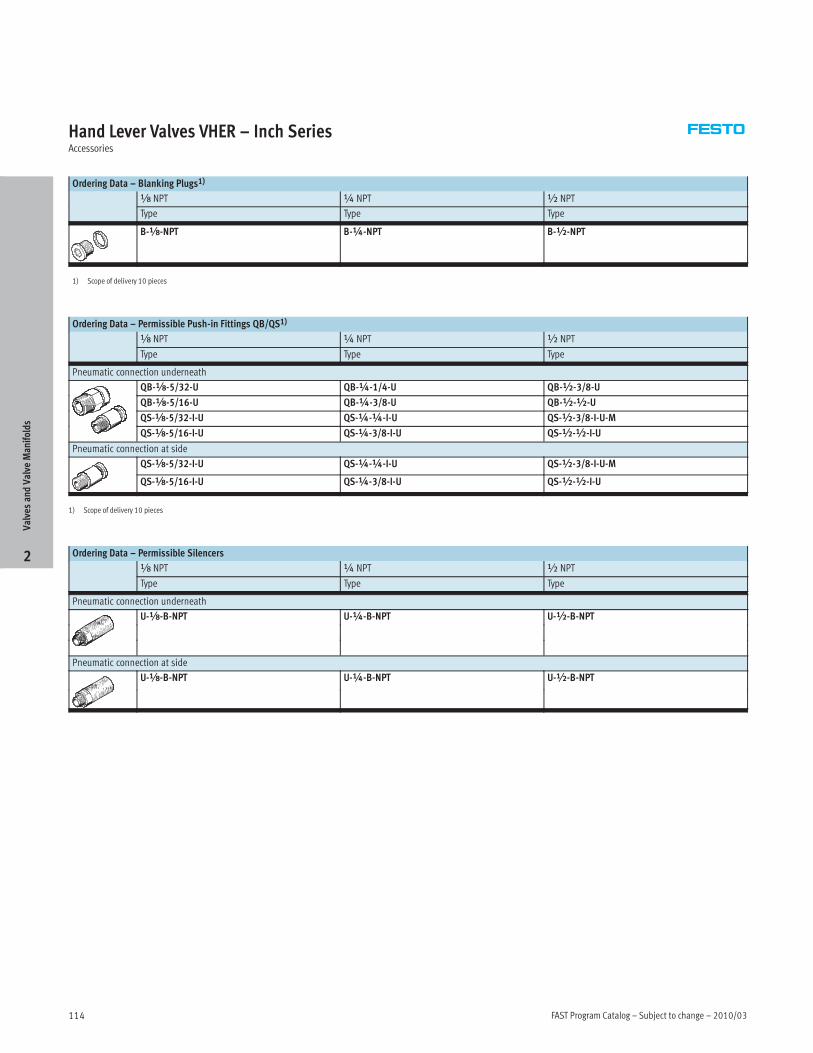
Hand Lever Valves VHER – Inch SeriesAccessories
Ordering Data – Blanking Plugs1)
x NPT ¼ NPT ½ NPT
Type Type Type
B-x-NPT B-¼-NPT B-½-NPT
1) Scope of delivery 10 pieces
Ordering Data – Permissible Push-in Fittings QB/QS1)
x NPT ¼ NPT ½ NPT
Type Type Type
Pneumatic connection underneath
QB-x-5/32-U QB-¼-1/4-U QB-½-3/8-U
QB-x-5/16-U QB-¼-3/8-U QB-½-½-U
QS-x-5/32-I-U QS-¼-¼-I-U QS-½-3/8-I-U-M
QS-x-5/16-I-U QS-¼-3/8-I-U QS-½-½-I-U
Pneumatic connection at side
QS-x-5/32-I-U QS-¼-¼-I-U QS-½-3/8-I-U-M
QS-x-5/16-I-U QS-¼-3/8-I-U QS-½-½-I-U
1) Scope of delivery 10 pieces
Ordering Data – Permissible Silencers
x NPT ¼ NPT ½ NPT
Type Type Type
Pneumatic connection underneath
U-x-B-NPT U-¼-B-NPT U-½-B-NPT
Pneumatic connection at side
U-x-B-NPT U-¼-B-NPT U-½-B-NPT
ValvesandValve
Manifolds
2
2010/03 – Subject to change – FAST Program Catalog 115
Hand Lever Valves VHER – Metric SeriesOverview
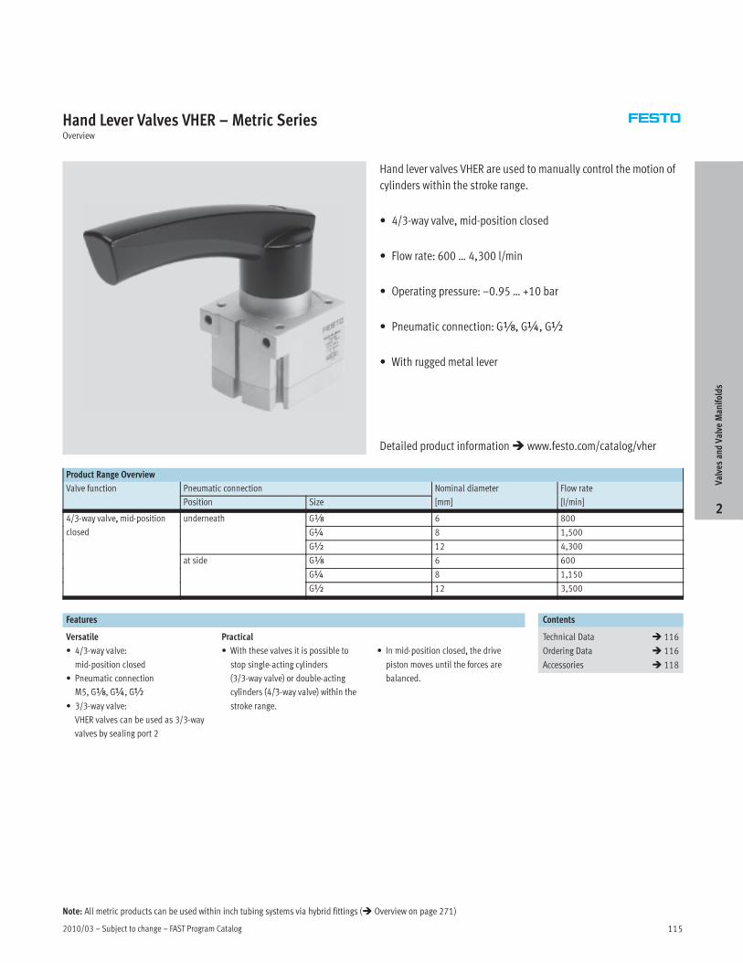
Hand lever valves VHER are used to manually control the motion of
cylinders within the stroke range.
• 4/3-way valve, mid-position closed
• Flow rate: 600 … 4,300 l/min
• Operating pressure: –0.95 … +10 bar
• Pneumatic connection: Gx, G¼, G½
• With rugged metal lever
Product Range Overview
Valve function Pneumatic connection Nominal diameter Flow rate
Position Size [mm] [l/min]
4/3-way valve, mid-position underneath Gx 6 800/3 y , p
closed G¼ 8 1,500
G½ 12 4,300
at side Gx 6 600
G¼ 8 1,150
G½ 12 3,500
Features Contents
Versatile Practical Technical Data � 116
• 4/3-way valve: • With these valves it is possible to • In mid-position closed, the drive Ordering Data � 116/ y
mid-position closed
p
stop single-acting cylinders
p ,
piston moves until the forces are Accessories � 118p
P ti ti
p g g y
(3/3 l ) d bl ti
p
b l d• Pneumatic connection
M5 Gx G¼ G½
(3/3-way valve) or double-acting
li d (4/3 l ) ithi th
balanced.
M5, Gx, G¼, G½
• 3/3-way valve:
VHER valves can be used as 3/3-way
valves by sealing port 2
cylinders (4/3-way valve) within the
stroke range.ValvesandValve
Manifolds
2
Detailed product information� www.festo.com/catalog/vher
Note: All metric products can be used within inch tubing systems via hybrid fittings (� Overview on page 271)

FAST Program Catalog – Subject to change – 2010/03116
Hand Lever Valves VHER – Metric SeriesTechnical Data
ISO Symbol
Mid-position closed
General Technical Data
Pneumatic connection 1,2,3,4 Gx G¼ G½
Actuator lock – –
Valve function 4/3-way, closed or exhausted
Design Rotary slide valve
Sealing principle Sliding disk
Type of mounting Option of front panel mounting or through-holes
Pilot control mode Direct
Actuation type Manual
Switching position display Via accessories
Assembly position Any
Direction of flow Reversible
Overlapping No
Standard nominal flow rate Ports underneath [l/min] 800 1,500 4,300
Ports at side [l/min] 600 1,150 3,500
Nominal diameter [mm] 6 8 12
Actuating torque at 10 bar [Nm] 1.1 2.8 5
Operating and Environmental Conditions
Operating medium Filtered compressed air and inert gases, lubricated or unlubricated
Filtration grade [µm] 40
Operating pressure [bar] –0.95 … +10
Ambient temperature [°C] –20 … +80
Corrosion resistance class CRC1) 2*
1) Corrosion resistance class 2 according to Festo standard 940 070
Components requiring moderate corrosion resistance. Externally visible parts with primarily decorative
surface requirements which are in direct contact with a normal industrial environment or media such as
coolants or lubricating agents.
ValvesandValve
Manifolds
2

2010/03 – Subject to change – FAST Program Catalog 117
Hand Lever Valves VHER – Metric SeriesTechnical Data, Ordering Data
Sectional View
Ports underneath Ports at side
1
1
Materials
1 Housing Die-cast aluminum
– Seals Nitrile rubber
– Contains PWIS (paint wetting impairment substances)
– Free of copper and PTFE
Ordering Data
Valve function Pneumatic connection Weight Type LT
Position Size [g]
Mid-position closed Underneath GÁ 220 VHER-AH-M04C-G18-UD 1Wp
G¼ 510 VHER-AH-M04C-G14-UD 1W
G½ 860 VHER-AH-M04C-G12-UD 1W
Side GÁ 260 VHER-AH-M04C-G18-LD 1W
G¼ 560 VHER-AH-M04C-G14-LD 1W
G½ 1,010 VHER-AH-M04C-G12-LD 1W
LT = Lead time 1D typically ships same day/next day 1W typically ships within 1 week
ValvesandValve
Manifolds
2

FAST Program Catalog – Subject to change – 2010/03118
Hand Lever Valves VHER – Metric SeriesAccessories
Assembled Valves with Accessories
12
Component parts and accessories Brief description � Page
1 Hand lever valves VHER Connection size Gx with metal lever 116
2 Hand lever valves VHER Connection size G¼ and G½ with metal lever 116
– Proximity sensors SME-10…1) Not included in scope of delivery 119
Connecting cables Not included in scope of delivery 119
Blanking plugs For use of hand lever valves VHER as 3/3-way valves; plugs not included in scope of delivery 120
Push-in fittings QS Not included in scope of delivery 120
Silencers Not included in scope of delivery 120
1) For valves with pneumatic connection at side, only proximity sensors SME-10… with lateral connection direction are permissible.
ValvesandValve
Manifolds
2
2010/03 – Subject to change – FAST Program Catalog 119
Hand Lever Valves VHER – Metric SeriesAccessories
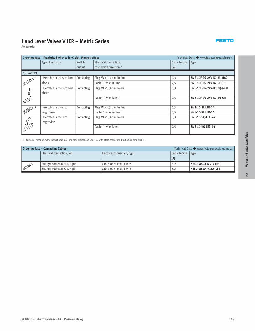
Ordering Data – Proximity Switches for C-slot, Magnetic Reed Technical Data� www.festo.com/catalog/sm
Type of mounting Switch Electrical connection, Cable length Typeyp g
output
,
connection direction1) [m]
yp
N/O contact
Insertable in the slot from Contacting Plug M8x1, 3-pin, in-line 0,3 SME-10F-DS-24V-K0,3L-M8D
above
g
Cable, 3-wire, in-line 2,5 SME-10F-DS-24V-K2,5L-OE
Insertable in the slot from
above
Contacting Plug M8x1, 3-pin, lateral 0,3 SME-10F-DS-24V-K0,3Q-M8D
Cable, 3-wire, lateral 2,5 SME-10F-DS-24V-K2,5Q-OE
Insertable in the slot Contacting Plug M8x1, 3-pin, in-line 0,3 SME-10-SL-LED-24
lengthwise
g
Cable, 3-wire, in-line 2,5 SME-10-KL-LED-24
Insertable in the slot
lengthwise
Contacting Plug M8x1, 3-pin, lateral 0,3 SME-10-SQ-LED-24
g
Cable, 3-wire, lateral 2,5 SME-10-KQ-LED-24
1) For valves with pneumatic connection at side, only proximity sensors SME-10… with lateral connection direction are permissible.
Ordering Data – Connecting Cables Technical Data� www.festo.com/catalog/nebu
Electrical connection, left Electrical connection, right Cable length Type, , g
[ft]
yp
Straight socket, M8x1, 3-pin Cable, open end, 3-wire 8.2 NEBU-M8G3-K-2.5-LE3
Straight socket, M8x1, 4-pin Cable, open end, 4-wire 8.2 NEBU-M8W4-K-2.5-LE4
ValvesandValve
Manifolds
2
FAST Program Catalog – Subject to change – 2010/03120
Hand Lever Valves VHER – Metric SeriesAccessories
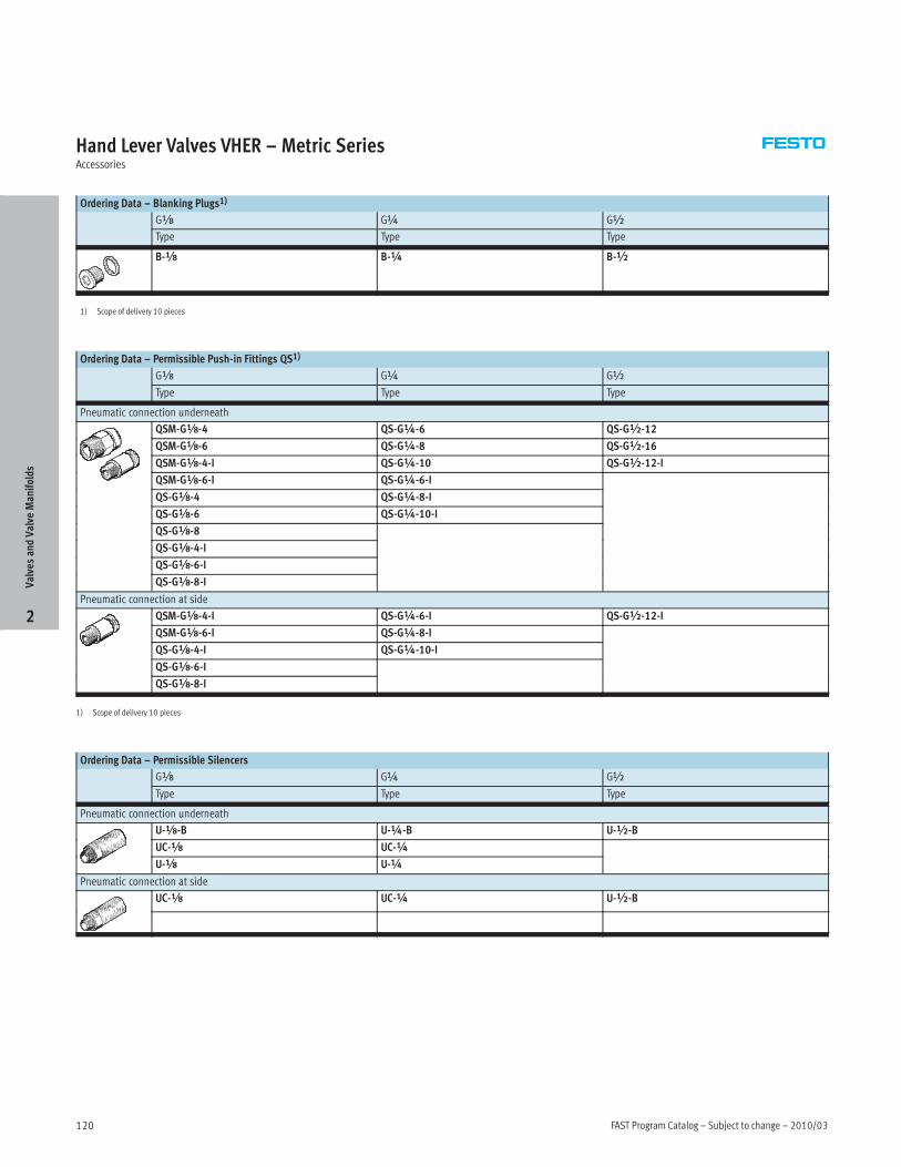
Ordering Data – Blanking Plugs1)
Gx G¼ G½
Type Type Type
B-x B-¼ B-½
1) Scope of delivery 10 pieces
Ordering Data – Permissible Push-in Fittings QS1)
Gx G¼ G½
Type Type Type
Pneumatic connection underneath
QSM-Gx-4 QS-G¼-6 QS-G½-12
QSM-Gx-6 QS-G¼-8 QS-G½-16
QSM-Gx-4-I QS-G¼-10 QS-G½-12-I
QSM-Gx-6-I QS-G¼-6-I
QS-Gx-4 QS-G¼-8-I
QS-Gx-6 QS-G¼-10-I
QS-Gx-8
QS-Gx-4-I
QS-Gx-6-I
QS-Gx-8-I
Pneumatic connection at side
QSM-Gx-4-I QS-G¼-6-I QS-G½-12-I
QSM-Gx-6-I QS-G¼-8-I
QS-Gx-4-I QS-G¼-10-I
QS-Gx-6-I
QS-Gx-8-I
1) Scope of delivery 10 pieces
Ordering Data – Permissible Silencers
Gx G¼ G½
Type Type Type
Pneumatic connection underneath
U-x-B U-¼-B U-½-B
UC-x UC-¼
U-x U-¼
Pneumatic connection at side
UC-x UC-¼ U-½-B
ValvesandValve
Manifolds
2

2010/03 – Subject to change – FAST Program Catalog 121
Solenoid Valves CPE, Compact PerformanceOverview
Performance optimized, compact valves for space-saving
installation.
• Width 10/14 mm, flow rates up to 900 l/min
• Maximum flow performance
• Minimal power consumption
• Small and powerful
• Short response times
• Assembly as individual valves or aluminummanifold rail
Product Range Overview
Actuation type Valve function qnN [l/min] Pilot air supply
Threaded connection M5, Gx
pp y
Solenoid coil 24 V DC 3/2 Normally closed 190 … 900 Internal/external3/
Normally open
9 9 /
5/2 Single solenoid 180 … 8005/
Double solenoid 180 … 800
5/3 Mid-position closed 180 … 7505/3
Mid-position pressurized
75
Mid-position exhausted
Contents
– Technical Data � 122
– Ordering Data � 124
– Accessories Overview � 125
– Accessories � 127
ValvesandValve
Manifolds
2
Detailed product information� www.festo.com/catalog/cpe
Note: All metric products can be used within inch tubing systems via hybrid fittings (� Overview on page 271)

FAST Program Catalog – Subject to change – 2010/03122
Solenoid Valves CPE, Compact PerformanceTechnical Data
General Technical Data
Size CPE10 CPE14
Pneumatic
connection
1, 2, 3, 4, 5 M5 Gx
Pilot air supply 12, 14 M3
Constructional design Piston spool valve
Type of mounting Via through-holes
Ambient temperature [°C] –5 … +50
Temperature of medium [°C] –5 … +50
Electrical data
Operating voltage [V DC] 24
Power consumption [W] 1.28
Protection class to IEC 60 529 With plug socket to IP65
3/2-way Valves, Normally Closed or Normally Open
Materials
End cap: Polyamide
Housing: Die-cast aluminum
Seals: Nitrile rubber
Technical Data Download CAD Data� www.festo.com/us/cad
Size CPE10 CPE14
Pneumatic connection M5 Gx
Operating pressure
Internal pilot air supply
[bar] 2.5 … 8
Operating pressure
External pilot pressure supply
[bar] –0.95 … +10
Pilot pressure [bar] 2.5 … 8
Standard nominal flow rate qnN [l/min] 190 900
Response time on/off [ms] 14/14 16/27
Length/width/height [mm] 61/10/35 71/14/40
ValvesandValve
Manifolds
2
2010/03 – Subject to change – FAST Program Catalog 123
Solenoid Valves CPE, Compact PerformanceTechnical Data
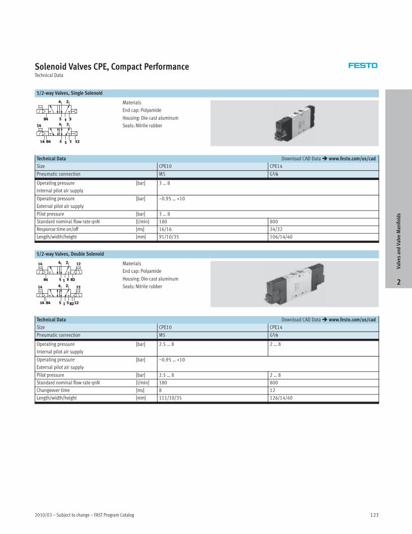
5/2-way Valves, Single Solenoid
Materials
End cap: Polyamide
Housing: Die-cast aluminum
Seals: Nitrile rubber
Technical Data Download CAD Data� www.festo.com/us/cad
Size CPE10 CPE14
Pneumatic connection M5 Gx
Operating pressure
Internal pilot air supply
[bar] 3 … 8
Operating pressure
External pilot air supply
[bar] –0.95 … +10
Pilot pressure [bar] 3 … 8
Standard nominal flow rate qnN [l/min] 180 800
Response time on/off [ms] 16/16 24/32
Length/width/height [mm] 91/10/35 106/14/40
5/2-way Valves, Double Solenoid
Materials
End cap: Polyamide
Housing: Die-cast aluminum
Seals: Nitrile rubber
Technical Data Download CAD Data� www.festo.com/us/cad
Size CPE10 CPE14
Pneumatic connection M5 Gx
Operating pressure
Internal pilot air supply
[bar] 2.5 … 8 2 … 8
Operating pressure
External pilot air supply
[bar] –0.95 … +10
Pilot pressure [bar] 2.5 … 8 2 … 8
Standard nominal flow rate qnN [l/min] 180 800
Changeover time [ms] 8 12
Length/width/height [mm] 111/10/35 126/14/40ValvesandValve
Manifolds
2
FAST Program Catalog – Subject to change – 2010/03124
Solenoid Valves CPE, Compact PerformanceOrdering Data
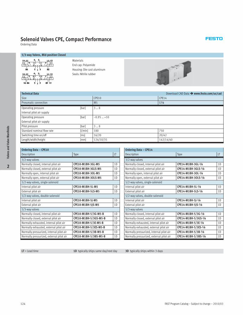
5/3-way Valves, Mid-position Closed
Materials
End cap: Polyamide
Housing: Die-cast aluminum
Seals: Nitrile rubber
Technical Data Download CAD Data� www.festo.com/us/cad
Size CPE10 CPE14
Pneumatic connection M5 Gx
Operating pressure
Internal pilot air supply
[bar] 3 … 8
Operating pressure
External pilot air supply
[bar] –0.95 … +10
Pilot pressure [bar] 3 … 8
Standard nominal flow rate [l/min] 180 750
Switching time on/off [ms] 16/20 20/42
Length/width/height [mm] 124/10/35 142/14/40
Ordering Data – CPE10
Description Type LT
3/2-way valves
Normally closed, internal pilot air CPE10-M1BH-3GL-M5 1D
Normally closed, external pilot air CPE10-M1BH-3GLS-M5 1D
Normally open, internal pilot air CPE10-M1BH-3OL-M5 1D
Normally open, external pilot air CPE10-M1BH-3OLS-M5 1D
5/2-way valves, single-solenoid
Internal pilot air CPE10-M1BH-5L-M5 1D
External pilot air CPE10-M1BH-5LS-M5 1D
5/2-way valves, double-solenoid
Internal pilot air CPE10-M1BH-5J-M5 1D
External pilot air CPE10-M1BH-5JS-M5 1D
5/3-way valves
Normally closed, internal pilot air CPE10-M1BH-5/3G-M5-B 1D
Normally closed, external pilot air CPE10-M1BH-5/3GS-M5-B 1D
Normally exhausted, internal pilot air CPE10-M1BH-5/3E-M5-B 1D
Normally exhausted, external pilot air CPE10-M1BH-5/3ES-M5-B 1D
Normally pressurized, internal pilot air CPE10-M1BH-5/3B-M5-B 1D
Normally pressurized, external pilot air CPE10-M1BH-5/3BS-M5-B 1D
Ordering Data – CPE14
Description Type LT
3/2-way valves
Normally closed, internal pilot air CPE14-M1BH-3GL-x 1D
Normally closed, external pilot air CPE14-M1BH-3GLS-x 1D
Normally open, internal pilot air CPE14-M1BH-3OL-x 1D
Normally open, external pilot air CPE14-M1BH-3OLS-x 1D
5/2-way valves, single-solenoid
Internal pilot air CPE14-M1BH-5L-x 1D
External pilot air CPE14-M1BH-5LS-x 1D
5/2-way valves, double-solenoid
Internal pilot air CPE14-M1BH-5J-x 1D
External pilot air CPE14-M1BH-5JS-x 1D
5/3-way valves
Normally closed, internal pilot air CPE14-M1BH-5/3G-x 1D
Normally closed, external pilot air CPE14-M1BH-5/3GS-x 1D
Normally exhausted, internal pilot air CPE14-M1BH-5/3E-x 1D
Normally exhausted, external pilot air CPE14-M1BH-5/3ES-x 1D
Normally pressurized, internal pilot air CPE14-M1BH-5/3B-x 1D
Normally pressurized, external pilot air CPE14-M1BH-5/3BS-x 1D
LT = Lead time 1D typically ships same day/next day 3D typically ships within 3 days
ValvesandValve
Manifolds
2
2010/03 – Subject to change – FAST Program Catalog 125
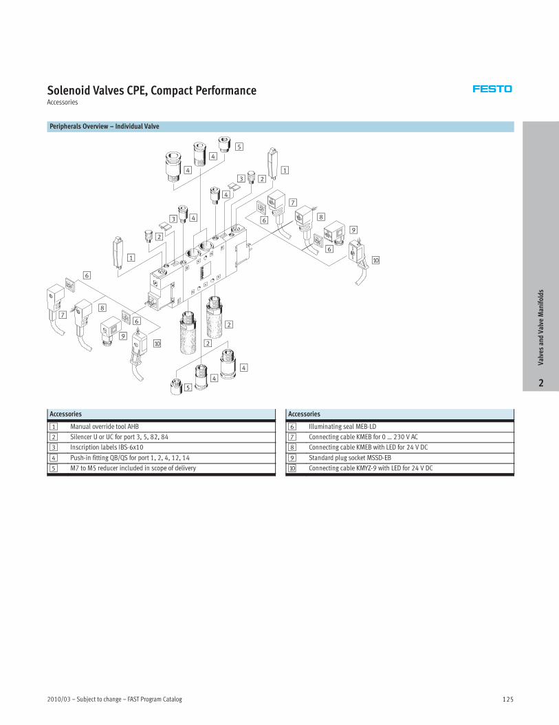
Solenoid Valves CPE, Compact PerformanceAccessories
Peripherals Overview – Individual Valve
9
8
aJ
123
4
6
5
43
2
1
4
4
2
2
54
4
6
6
6
7
7
8
9
aJ
Accessories
1 Manual override tool AHB
2 Silencer U or UC for port 3, 5, 82, 84
3 Inscription labels IBS-6x10
4 Push-in fitting QB/QS for port 1, 2, 4, 12, 14
5 M7 to M5 reducer included in scope of delivery
Accessories
6 Illuminating seal MEB-LD
7 Connecting cable KMEB for 0 … 230 V AC
8 Connecting cable KMEB with LED for 24 V DC
9 Standard plug socket MSSD-EB
aJ Connecting cable KMYZ-9 with LED for 24 V DC
ValvesandValve
Manifolds
2

FAST Program Catalog – Subject to change – 2010/03126
Solenoid Valves CPE, Compact PerformanceAccessories
Peripherals Overview – Mounting on Manifold Block
1
1
3
2
2
5
6
8
9
aB
aA
4
4
7
8
aB
aC
aD
7
9
aA
5
3
aJ
aJ
Accessories
1 Plug socket with cable KMEB-1 with LED for 24 V DC
2 Plug socket with cable KMEB-1 for 0 … 230 V AC
3 Standard plug socket MSSD-EB
4 Plug socket with cable KMEB-2 for 0 … 230 V AC
5 Illuminating seal MEB-LED
6 Inscription label IBS 6x10
7 Quick Star push-in fitting QB/QS for port 12, 14, for tubing of standard O.D.
Accessories
8 Quick Star push-in fitting QB/QS for port 2, 4, for tubing of standard O.D.
9 Blanking plug B
aJ Quick Star push-in fitting QB/QS for port 5, for tubing of standard O.D.
aA Silencer U or UC for fitting in exhaust ports
aB Separator for pressure zones VABD, PRSV for fitting in the manifold block
aC Blanking plate CPE-RP for fitting on unused valve positions
aD Manifold block CPE-PRS
ValvesandValve
Manifolds
2

2010/03 – Subject to change – FAST Program Catalog 127
Solenoid Valves CPE, Compact PerformanceAccessories
Ordering Data – Manifold Blocks, Inch Series
Valve positions Order code LT
Manifold block CPE10
2 CPE10-PRS-¼-2-NPT 3D
3 CPE10-PRS-¼-3-NPT 3D
4 CPE10-PRS-¼-4-NPT 3D
5 CPE10-PRS-¼-5-NPT 3D
6 CPE10-PRS-¼-6-NPT 3D
7 CPE10-PRS-¼-7-NPT 3D
8 CPE10-PRS-¼-8-NPT 3D
9 CPE10-PRS-¼-9-NPT 3D
10 CPE10-PRS-¼-10-NPT 3D
Manifold block CPE14
2 CPE14-PRS-y-2-NPT 3D
3 CPE14-PRS-y-3-NPT 3D
4 CPE14-PRS-y-4-NPT 3D
5 CPE14-PRS-y-5-NPT 3D
6 CPE14-PRS-y-6-NPT 3D
7 CPE14-PRS-y-7-NPT 3D
8 CPE14-PRS-y-8-NPT 3D
9 CPE14-PRS-y-9-NPT 3D
10 CPE14-PRS-y-10-NPT 3D
Ordering Data – Push-in Fittings QB/QS, Inch Series
Technical Data� 275
Function For thread Tubing O.D. Order code LTg
[in]
M7 3/16 QSM-M7-3/16-I-U-M 1D7
1/4 QSM-M7-1/4-I-U-M 1D
GÁ 1/4 QS-H-1/8-1/4-U-M 1DÁ
5/16 QS-H-1/8-5/16-U-M 1D
¼NPT 5/16 QB-1/4-5/16-U 1D¼
3/8 QB-1/4-3/8-U 1D
ÅNPT 3/8 QB-3/8-3/8-U 1DÅ
1/2 QB-3/8-1/2-U 1D
Ordering Data – Blanking Plates, Retainers
Size Order code LT
CPE10 CPE10-RP 1D
CPE14 CPE14-RP 1D
CPE10 CPE10-H5-SET 1D
CPE14 CPE14-H5-SET 1D
Ordering Data – Manifold Blocks, Metric Series
Valve positions Order code LT
Manifold block CPE10
2 CPE10-PRS-¼-2 3D
3 CPE10-PRS-¼-3 3D
4 CPE10-PRS-¼-4 3D
5 CPE10-PRS-¼-5 3D
6 CPE10-PRS-¼-6 3D
7 CPE10-PRS-¼-7 3D
8 CPE10-PRS-¼-8 3D
9 CPE10-PRS-¼-9 3D
10 CPE10-PRS-¼-10 3D
Manifold block CPE14
2 CPE14-PRS-y-2 3D
3 CPE14-PRS-y-3 3D
4 CPE14-PRS-y-4 3D
5 CPE14-PRS-y-5 3D
6 CPE14-PRS-y-6 3D
7 CPE14-PRS-y-7 3D
8 CPE14-PRS-y-8 3D
9 CPE14-PRS-y-9 3D
10 CPE14-PRS-y-10 3D
Ordering Data – Push-in Fittings QS, Metric Series
Technical Data� 275
Function For thread Tubing O.D. Order code LTg
[mm]
M7 4 QSM-M7-4-I 1D7
6 QSM-M7-6-I 1D
GÁ 6 QS-1/8-6 1DÁ
8 QS-1/8-8 1D
G¼ 8 QS-1/4-8 1D¼
10 QS-1/4-10 1D
GÅ 10 QS-3/8-10 1DÅ
12 QS-3/8-12 1D
Ordering Data – General Accessories
Order code LT
Silencer
For CPE10 UC-M7 1D
For CPE14 UC-x 1D
For CPE10/CPE14 U-M3 1D
For CPE10-PRS U-¼-B 1D
For CPE14-PRS U-y-B 1D
Ordering Data – Connecting Cables
Voltage Length [m] Order code LT
24 V DC 2.5 KMYZ-9-24-2,5-LED-PUR-B 1D
5 KMYZ-9-24-5-LED-PUR-B 1D
10 KMYZ-9-24-10-LED-PUR-B 1D
ValvesandValve
Manifolds
2

FAST Program Catalog – Subject to change – 2010/03128
ValvesandValve
Manifolds
2
This page intentionally left blank.

2010/03 – Subject to change – FAST Program Catalog 129
Valve Manifolds Type 32 MPAOverview
• Width 10/20 mm, flow rate up to 700 l/min
• Modular valve terminal with internal communication system for
up to 128 valves
• Extensive functional integration: pressure sensors, pressure
regulators, proportional pressure regulators, electrical voltage
zones
• Mixture of valve sizes possible, simple valve replacement
• Design optimized for electrical peripherals CPX, extensive
electrical networking possible
• Extensive channel-oriented diagnostics down to the individual
valve, integrated condition monitoring and coil current
monitoring
Key Features
Innovative Flexible Reliable Easy to mount
• Low-profile, high-performance valves
in sturdy metal housing
• MPA1 flow rate up to 360 l/min
• MPA2 flow rate up to 700 l/min
• Standardized from the individual
valve up to multi-pin plug and
fieldbus connections and control
block
• Dream team: fieldbus valve terminal
suitable for electrical peripherals
CPX. This means
– Advanced internal communication
system for activation of the valves
and CPX modules
– Diagnosis down to the individual
valve
– Valves can either be activated via
electrical isolation or without
(standard)
• Modular system offering a range of
configuration options
• Expandable up to 128 solenoid coils
• Up to 24 valve positions with
multi-pin plug connection, and up to
64 valve positions with fieldbus
connection (CPX terminal)
• Can be easily modified in the field
• Manifold sub-bases can be expanded
using just three screws and sturdy
separating seals on metal separator
plates
• Integration of innovative function
modules possible
• Supply plates permit a flexible air
supply and variable pressure zones
• High pressure range
–0.9 … 10 bar
• Wide range of valve functions
• Sturdy and durable metal
components
– Valves
– Manifold sub-bases
– Seals
• Fast troubleshooting thanks to LEDs
on the valves and diagnosis via
fieldbus
• High operating voltage tolerance
±25%
• Reliable servicing through
replaceable valves and electronics
modules
• Manual override either pushing,
detenting or secured against
unauthorized activation (covered)
• Durable thanks to the use of
tried-and-tested piston spool valves
• Large and durable labelling system,
suitable for barcodes
• Ready-to-install unit, already
assembled and tested
• Lower costs for selection, ordering,
assembly and commissioning
• Secure wall mounting or H-rail
mounting
Contents
– Options Overview � 130
– Technical Data � 132
– Ordering Data � 134
– Accessories Overview � 135
ValvesandValve
Manifolds
2
Detailed product information� www.festo.com/catalog/mpa
Note: All metric products can be used within inch tubing systems via hybrid fittings (� Overview on page 271)
FAST Program Catalog – Subject to change – 2010/03130
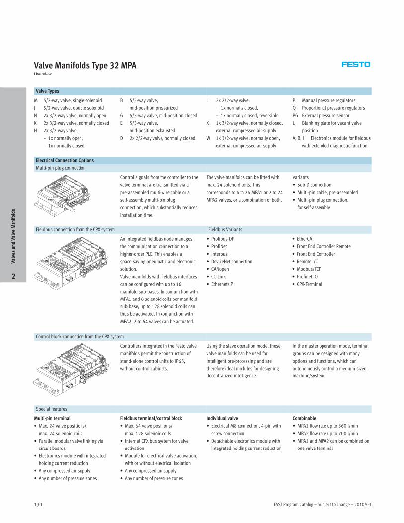
Valve Manifolds Type 32 MPAOverview
Valve Types
M 5/2-way valve, single solenoid
J 5/2-way valve, double solenoid
N 2x 3/2-way valve, normally open
K 2x 3/2-way valve, normally closed
H 2x 3/2-way valve,
– 1x normally open,
– 1x normally closed
B 5/3-way valve,
mid-position pressurized
G 5/3-way valve, mid-position closed
E 5/3-way valve,
mid-position exhausted
D 2x 2/2-way valve, normally closed
I 2x 2/2-way valve,
– 1x normally closed,
– 1x normally closed, reversible
X 1x 3/2-way valve, normally closed,
external compressed air supply
W 1x 3/2-way valve, normally open,
external compressed air supply
P Manual pressure regulators
Q Proportional pressure regulators
PG External pressure sensor
L Blanking plate for vacant valve
position
A, B, H Electronics module for fieldbus
with extended diagnostic function
Electrical Connection Options
Multi-pin plug connection
Control signals from the controller to the
valve terminal are transmitted via a
pre-assembled multi-wire cable or a
self-assembly multi-pin plug
connection, which substantially reduces
installation time.
The valve manifolds can be fitted with
max. 24 solenoid coils. This
corresponds to 4 to 24 MPA1 or 2 to 24
MPA2 valves, or a combination of both.
Variants
• Sub-D connection
• Multi-pin cable, pre-assembled
• Multi-pin plug connection,
for self-assembly
Fieldbus connection from the CPX system Fieldbus Variants
An integrated fieldbus node manages
the communication connection to a
higher-order PLC. This enables a
space-saving pneumatic and electronic
solution.
Valve manifolds with fieldbus interfaces
can be configured with up to 16
manifold sub-bases. In conjunction with
MPA1 and 8 solenoid coils per manifold
sub-base, up to 128 solenoid coils can
thus be activated. In conjunction with
MPA2, 2 to 64 valves can be actuated.
• Profibus-DP
• ProfiNet
• Interbus
• DeviceNet connection
• CANopen
• CC-Link
• Ethernet/IP
• EtherCAT
• Front End Controller Remote
• Front End Controller
• Remote I/O
• Modbus/TCP
• Profinet IO
• CPX-Terminal
Control block connection from the CPX system
Controllers integrated in the Festo valve
manifolds permit the construction of
stand-alone control units to IP65,
without control cabinets.
Using the slave operation mode, these
valve manifolds can be used for
intelligent pre-processing and are
therefore ideal modules for designing
decentralized intelligence.
In the master operation mode, terminal
groups can be designed with many
options and functions, which can
autonomously control a medium-sized
machine/system.
Special features
Multi-pin terminal
• Max. 24 valve positions/
max. 24 solenoid coils
• Parallel modular valve linking via
circuit boards
• Electronics module with integrated
holding current reduction
• Any compressed air supply
• Any number of pressure zones
Fieldbus terminal/control block
• Max. 64 valve positions/
max. 128 solenoid coils
• Internal CPX bus system for valve
activation
• Module for electrical valve activation,
with or without electrical isolation
• Any compressed air supply
• Any number of pressure zones
Individual valve
• Electrical M8 connection, 4-pin with
screw connection
• Detachable electronics module with
integrated holding current reduction
Combinable
• MPA1 flow rate up to 360 l/min
• MPA2 flow rate up to 700 l/min
• MPA1 and MPA2 can be combined on
one valve terminal
ValvesandValve
Manifolds
2
2010/03 – Subject to change – FAST Program Catalog 131
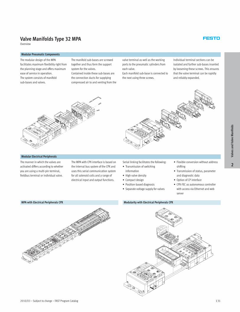
Valve Manifolds Type 32 MPAOverview
Modular Pneumatic Components
The modular design of the MPA
facilitates maximum flexibility right from
the planning stage and offers maximum
ease of service in operation.
The system consists of manifold
sub-bases and valves.
The manifold sub-bases are screwed
together and thus form the support
system for the valves.
Contained inside these sub-bases are
the connection ducts for supplying
compressed air to and venting from the
valve terminal as well as the working
ports to the pneumatic cylinders from
each valve.
Each manifold sub-base is connected to
the next using three screws.
Individual terminal sections can be
isolated and further sub-bases inserted
by loosening these screws. This ensures
that the valve terminal can be rapidly
and reliably expanded.
Modular Electrical Peripherals
The manner in which the valves are
activated differs according to whether
you are using a multi-pin terminal,
fieldbus terminal or individual valve.
The MPA with CPX interface is based on
the internal bus system of the CPX and
uses this serial communication system
for all solenoid coils and a range of
electrical input and output functions.
Serial linking facilitates the following:
• Transmission of switching
information
• High valve density
• Compact design
• Position-based diagnosis
• Separate voltage supply for valves
• Flexible conversion without address
shifting
• Transmission of status, parameter
and diagnostic data
• Option of CP interface
• CPX-FEC as autonomous controller
with access via Ethernet and web
server
MPA with Electrical Peripherals CPX Modularity with Electrical Peripherals CPX
ValvesandValve
Manifolds
2
FAST Program Catalog – Subject to change – 2010/03132
Valve Manifolds Type 32 MPATechnical Data
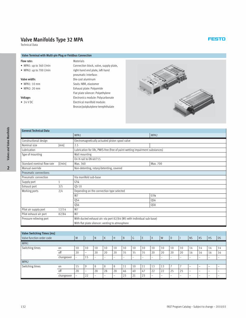
Valve Terminal with Multi-pin Plug or Fieldbus Connection
Flow rate:
• MPA1: up to 360 l/min
• MPA2: up to 700 l/min
Valve width:
• MPA1: 10 mm
• MPA2: 20 mm
Voltage:
• 24 V DC
Materials
Connection block, valve, supply plate,
right-hand end plate, left-hand
pneumatic interface:
Die-cast aluminum
Seals: NBR, elastomer
Exhaust plate: Polyamide
Flat plate silencer: Polyethylene
Electronics module: Polycarbonate
Electrical manifold module:
Bronze/polybutylene terephthalate
General Technical Data
MPA1 MPA2
Constructional design Electromagnetically actuated piston spool valve
Nominal size [mm] 2.5
Lubrication Lubrication for life, PWIS-free (free of paint-wetting impairment substances)
Type of mounting Wall mountingyp g
On H-rail to EN 60715
Standard nominal flow rate [l/min] Max. 360 Max. 700
Manual override Non-detenting, rotary/detenting, covered
Pneumatic connections
Pneumatic connection Via manifold sub-base
Supply port 1 G¼
Exhaust port 3/5 QS-10
Working ports 2/4 Depending on the connection type selectedg p /
M7 Gx
QS4 QS6
QS6 QS8
Pilot air supply port 12/14 M7
Pilot exhaust air port 82/84 M7
Pressure relieving port With ducted exhaust air: via port 82/84 (M5 with individual sub-base)
With flat plate silencer: venting to atmosphere
Valve Switching Times [ms]
Valve function order code M J N K H B G E X W D I NS KS HS DS
MPA1
Switching times on 10 10 10 10 10 10 10 10 10 10 10 10 14 14 14 14g
off 20 – 20 20 20 35 35 35 20 20 20 20 16 16 16 16
changeover – 15 – – – – – – – – – – – – – –
MPA2
Switching times on 15 9 8 8 8 11 10 11 13 13 7 7 – – – –g
off 28 – 28 28 28 46 40 47 22 22 25 25 – – – –
changeover – 22 – – – 23 21 23 – – – – – – – –
ValvesandValve
Manifolds
2
2010/03 – Subject to change – FAST Program Catalog 133
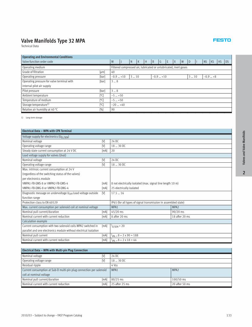
Valve Manifolds Type 32 MPATechnical Data
Operating and Environmental Conditions
Valve function order code M J N K H B G E X W D I NS KS HS DS
Operating medium Filtered compressed air, lubricated or unlubricated, inert gases
Grade of filtration [µm] 40
Operating pressure [bar] –0.9 … +10 3 … 10 –0.9 … +10 3 … 10 –0.9 … +8
Operating pressure for valve terminal with
internal pilot air supply
[bar] 3 … 8
Pilot pressure [bar] 3 … 8
Ambient temperature [°C] –5 … +50
Temperature of medium [°C] –5 … +50
Storage temperature1) [°C] –20 … +40
Relative air humidity at 40 °C [%] 90
1) Long-term storage
Electrical Data – MPA with CPX Terminal
Voltage supply for electronics (UEL/SEN)
Nominal voltage [V] 24 DC
Operating voltage range [V] 18 … 30 DC
Steady state current consumption at 24 V DC [mA] 20
Load voltage supply for valves (Uval)
Nominal voltage [V] 24 DC
Operating voltage range [V] 18 … 30 DC
Max. intrinsic current consumption at 24 V
(regardless of the switching status of the valves)
per electronics module
VMPA1-FB-EMS-8 or VMPA2-FB-EMS-4
VMPA1-FB-EMG-8 or VMPA2-FB-EMG-4
[mA]
[mA]
8 not electrically isolated (max. signal line length 10 m)
25 electrically isolated
Diagnostic message on undervoltage UOFF Load voltage outside
function range
[V] 17.5 … 16
Protection class to EN 60529 IP65 (for all types of signal transmission in assembled state)
Max. current consumption per solenoid coil at nominal voltage MPA1 MPA2
Nominal pull current/duration [mA] 45/20 ms 90/20 ms
Nominal current with current reduction [mA] 8 after 20 ms 18 after 20 ms
Calculation example
Current consumption with two solenoid coils MPA2 switched in
parallel and one electronics module without electrical isolation
[mA] IEl/SEN= 20
Nominal pull current [mA] IVAL =8 + 2 x 90 = 188
Nominal current with current reduction [mA] IVAL =8 + 2 x 18 = 44
Electrical Data – MPA with Multi-pin Plug Connection
Nominal voltage [V] 24 DC
Operating voltage range [V] 18 … 30 DC
Residual ripple 4 Vss
Current consumption at Sub-D multi-pin plug connection per solenoid
coil at nominal voltage
MPA1 MPA2
Nominal pull current/duration [mA] 80/25 ms 100/50 ms
Nominal current with current reduction [mA] 25 after 25 ms 20 after 50 ms
ValvesandValve
Manifolds
2

FAST Program Catalog – Subject to change – 2010/03134
Valve Manifolds Type 32 MPAOrdering Data
Valve Terminal Configurator Online via:� www.festo.com/us/engineering
The appropriate MPA valve terminal can
be chosen quickly and easily using the
online catalog. This includes an easy-to-
use valve terminal configurator, which
makes it much easier for you to find the
right product.
The valve manifolds are fully assembled
according to your order specifications
and are individually tested. This re-
duces assembly and installation time to
a minimum.
You order a valve terminal type 32 using
the order code.
Ordering system for type 32
� Internet: mpa
Ordering system, CPX
� Internet: cpx
The illustration above provides an
example of a valve terminal
configuration.
The following steps explain how you ar-
rive at the order code:
Once you have called up
� www.festo.com, click on
“Automation” and select “Catalog” from
the “Products” submenu. Now select
“Valve manifolds” and then “Universal
Valve manifolds”. Select your desired
valve terminal (in this case MPA) and
click on the link “Configure common
options”.
You can then configure the valve ter-
minal step by step (from left to right) ac-
cording to your requirements. Now click
on the shopping basket to save the se-
lected configuration (this will not trigger
an order).
You can change to expert mode at any
time via the link “Further options”. In
expert mode, advanced options are
available for you to configure your valve
terminal.
2D/3D CAD Data Online via:� www.festo.com/us/engineering
You can request the CAD data for a valve
terminal you have configured. To do
this, perform the product search as de-
scribed above. Enter the shopping
basket and click on the CAD icon (com-
pass). On the next screen you can gener-
ate a 3D preview or request another
data format of your choice by e-mail.
ValvesandValve
Manifolds
2
Lead Time LT for all configurable options on this page: 3D typically ships within 3 days
2010/03 – Subject to change – FAST Program Catalog 135
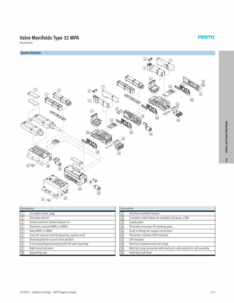
Valve Manifolds Type 32 MPAAccessories
System Overview
2
3
5
1 6
7
9
5
76
aJ
aD
aE
aA
aD
aB
aF
aG8
aH8
aB
aC
aA
8
aI
4
4
aJ
aJ
aJ
aE
aE
bJ
8
Accessories
1 Inscription label, large
2 Flat plate silencer
3 Exhaust plate for ducted exhaust air
4 Electronics module MPA1 or MPA2
5 Valve MPA1 or MPA2
6 Cover for manual override (pushing, covered only)
7 Blanking plate for vacant valve position
8 H-rail mounting/mounting bracket for wall mounting
9 Right-hand end plate
aJ Separating seal
Accessories
aA Electrical manifold module
aB Inscription label holder for manifold sub-base, 4-fold
aC Supply plate
aD Threaded connectors for working ports
aE Push-in fittings for supply connections
aF Pneumatic interface (CPX interface)
aG CPX modules
aH Electrical interface (multi-pin plug)
aI Multi-pin plug connection with multi-pin cable and/or for self-assembly
bJ Individual sub-base
ValvesandValve
Manifolds
2

FAST Program Catalog – Subject to change – 2010/03136
ValvesandValve
Manifolds
2
This page intentionally left blank.
2010/03 – Subject to change – FAST Program Catalog 137
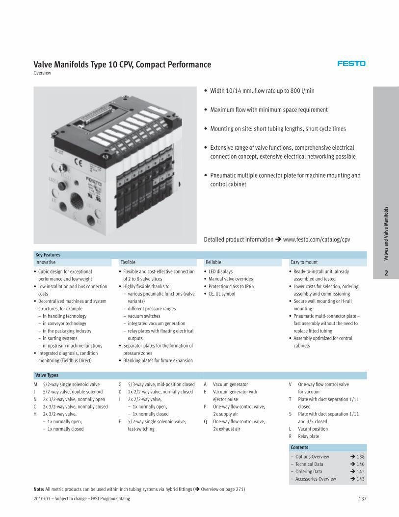
Valve Manifolds Type 10 CPV, Compact PerformanceOverview
• Width 10/14 mm, flow rate up to 800 l/min
• Maximum flow with minimum space requirement
• Mounting on site: short tubing lengths, short cycle times
• Extensive range of valve functions, comprehensive electrical
connection concept, extensive electrical networking possible
• Pneumatic multiple connector plate for machine mounting and
control cabinet
Key Features
Innovative Flexible Reliable Easy to mount
• Cubic design for exceptional
performance and low weight
• Low installation and bus connection
costs
• Decentralized machines and system
structures, for example
– in handling technology
– in conveyor technology
– in the packaging industry
– in sorting systems
– in upstream machine functions
• Integrated diagnosis, condition
monitoring (Fieldbus Direct)
• Flexible and cost-effective connection
of 2 to 8 valve slices
• Highly flexible thanks to:
– various pneumatic functions (valve
variants)
– different pressure ranges
– vacuum switches
– integrated vacuum generation
– relay plates with floating electrical
outputs
• Separator plates for the formation of
pressure zones
• Blanking plates for future expansion
• LED displays
• Manual valve overrides
• Protection class to IP65
• CE, UL symbol
• Ready-to-install unit, already
assembled and tested
• Lower costs for selection, ordering,
assembly and commissioning
• Secure wall mounting or H-rail
mounting
• Pneumatic multi-connector plate –
fast assembly without the need to
replace fitted tubing
• Assembly optimized for control
cabinets
Valve Types
M 5/2-way single solenoid valve
J 5/2-way valve, double solenoid
N 2x 3/2-way valve, normally open
C 2x 3/2-way valve, normally closed
H 2x 3/2-way valve,
– 1x normally open,
– 1x normally closed
G 5/3-way valve, mid-position closed
D 2x 2/2-way valve, normally closed
I 2x 2/2-way valve,
– 1x normally open,
– 1x normally closed
F 5/2-way single solenoid valve,
fast-switching
A Vacuum generator
E Vacuum generator with
ejector pulse
P One-way flow control valve,
2x supply air
Q One-way flow control valve,
2x exhaust air
V One-way flow control valve
for vacuum
T Plate with duct separation 1/11
closed
S Plate with duct separation 1/11
and 3/5 closed
L Vacant position
R Relay plate
Contents
– Options Overview � 138
– Technical Data � 140
– Ordering Data � 142
– Accessories Overview � 143
ValvesandValve
Manifolds
2
Detailed product information� www.festo.com/catalog/cpv
Note: All metric products can be used within inch tubing systems via hybrid fittings (� Overview on page 271)

FAST Program Catalog – Subject to change – 2010/03138
Valve Manifolds Type 10 CPV, Compact PerformanceOverview
Advantages at a Glance
The CPV valve terminal is of unique
design. It permits the flexible
combination of pneumatic performance,
electrical connection technologies and a
wide range of mounting options. The
generously sized flow ducts and
powerful flat plate silencers ensure high
flow rates. This means that even
comparatively large pneumatic cylinders
can be driven with ease.
All valves are in the form of valve slices.
They are optimized for flow performance
and are also extremely compact. Two
functions per valve slice
(e.g. 2x 3/2-way valves) mean that twice
the component density can be achieved.
This saves space and reduces costs.
The cubic design permits exceptional
performance yet a comparatively low
weight. The benefits of this design are
obvious when the valve terminal is used
on a moving installation.
However robustness must not be
sacrificed in favor of compactness. The
connecting thread and mounting
attachments are metallic.
The manual override for the valves can
be adapted for different operating
situations. If, for example, a detenting
manual override is required for
setting-up mode, the manual override
can be easily converted for that
application in a way that rules out
operational errors. The clear, large
labelling system also contributes to the
safe operation of the valve terminal.
A particular plus is the range of
electrical connection technologies
supported. All types of valve activation
are possible, from individual valve
connections up to bus systems with
versatile expansion options. The
integration of electrical input and
output modules permits cost-effective
solutions within the different
installation concepts.
Made-to-measure pneumatics Variable compressed air supply Easy assembly technology
• Exceptional performance and low
weight
• Blanking plates for future expansion
• LED displays
• Manual valve overrides
• Low installation and bus connection
costs
• Protection class to IP65
• Variable compressed air supply that
can be adapted to the relevant
requirements
• Modules for additional compressed
air supply and exhaust
• Choice of assembly on H-rail or
profile/backwall
• Adaptable assembly with connectors
for different tubing diameters
Design Principle
The cubic design provides a clearly
assigned function on each side. Thus,
for example, the electrical connection is
mounted on the top surface. An optional
inscription label holder can be placed
on the front of the valve terminal. The
different combination options ensure
the optimum solution for the task at
hand.
• Pneumatic supply connections on the
left, right or underneath
• Pneumatic working ports and
functional modules (vertical stacking)
underneath
• Manual operation/identification on
the front
• Electrical connection surface on the
top
• Mounting surface at the back or even
at the front via a pneumatic
multi-connector plate
Valves
CPV valves are integrated sub-base
valves, i.e. in addition to the valve
function they contain all of the
pneumatic ducts for supply, exhaust
and the working ports. The supply ducts
are a central component of the valve
slices and allow a direct flow of air
through the valve slices.
This helps achieve maximum flow rates.
All valves have pneumatic pilot control
for optimising performance. The valve
function is based on a piston spool
system with a patented sealing principle
that guarantees its suitability for a wide
range of applications as well as a long
service life.
The pneumatic components and
functions are always identical for all
actuator types. Most functions are also
available in the various valve sizes
(spacing). Restrictions are noted where
applicable.
Pressure zones
Different pressures at port 1 and 11
result in two pressure levels per valve.
This means, for example, that a cylinder
drive can be extended with high
pressure and retracted with low
pressure to save energy.
The maximum number of pressure
zones possible is determined by the
combination of the following
components:
• Use of a separator plate
• End plate pair type
• Valve slice type
You can divide the CPV valve terminal
into 2 to 4 pressure zones by using
separator plates.
ValvesandValve
Manifolds
2
2010/03 – Subject to change – FAST Program Catalog 139
Valve Manifolds Type 10 CPV, Compact PerformanceOverview
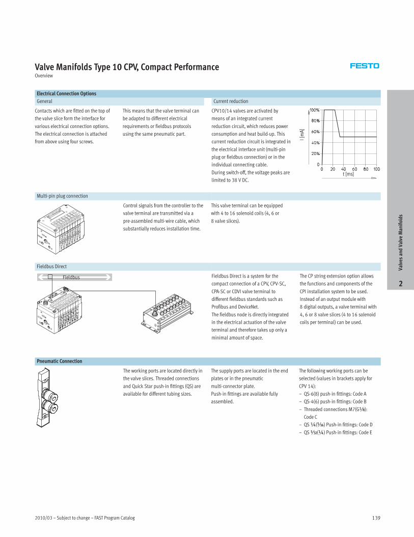
Electrical Connection Options
General Current reduction
Contacts which are fitted on the top of
the valve slice form the interface for
various electrical connection options.
The electrical connection is attached
from above using four screws.
This means that the valve terminal can
be adapted to different electrical
requirements or fieldbus protocols
using the same pneumatic part.
CPV10/14 valves are activated by
means of an integrated current
reduction circuit, which reduces power
consumption and heat build-up. This
current reduction circuit is integrated in
the electrical interface unit (multi-pin
plug or fieldbus connection) or in the
individual connecting cable.
During switch-off, the voltage peaks are
limited to 38 V DC.t [ms]
I[mA]
Multi-pin plug connection
Control signals from the controller to the
valve terminal are transmitted via a
pre-assembled multi-wire cable, which
substantially reduces installation time.
This valve terminal can be equipped
with 4 to 16 solenoid coils (4, 6 or
8 valve slices).
Fieldbus Direct
Fieldbus Fieldbus Direct is a system for the
compact connection of a CPV, CPV-SC,
CPA-SC or CDVI valve terminal to
different fieldbus standards such as
Profibus and DeviceNet.
The fieldbus node is directly integrated
in the electrical actuation of the valve
terminal and therefore takes up only a
minimal amount of space.
The CP string extension option allows
the functions and components of the
CPI installation system to be used.
Instead of an output module with
8 digital outputs, a valve terminal with
4, 6 or 8 valve slices (4 to 16 solenoid
coils per terminal) can be used.
Pneumatic Connection
The working ports are located directly in
the valve slices. Threaded connections
and Quick Star push-in fittings (QS) are
available for different tubing sizes.
The supply ports are located in the end
plates or in the pneumatic
multi-connector plate.
Push-in fittings are available fully
assembled.
The following working ports can be
selected (values in brackets apply for
CPV 14):
– QS-6(8) push-in fittings: Code A
– QS-4(6) push-in fittings: Code B
– Threaded connections M7(GÁ):
Code C
– QS¼(Ä) Push-in fittings: Code D
– QSÂ(¼) Push-in fittings: Code E
ValvesandValve
Manifolds
2
FAST Program Catalog – Subject to change – 2010/03140
Valve Manifolds Type 10 CPV, Compact PerformanceTechnical Data
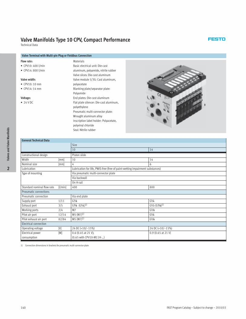
Valve Terminal with Multi-pin Plug or Fieldbus Connection
Flow rate:
• CPV10: 400 l/min
• CPV14: 800 l/min
Valve width:
• CPV10: 10 mm
• CPV14: 14 mm
Voltage:
• 24 V DC
Materials
Basic electrical unit: Die-cast
aluminum, polyamide, nitrile rubber
Valve slices: Die-cast aluminum
Valve module 5/3G: Cast aluminum,
polyacetate
Blanking plate/separator plate:
Polyamide
End plates: Die-cast aluminum
Flat plate silencer: Die-cast aluminum,
polyethylene
Pneumatic multi-connector plate:
Wrought aluminum alloy
Inscription label holder: Polyacetate,
polyvinyl chloride
Seal: Nitrile rubber
General Technical Data
Size
10 14
Constructional design Piston slide
Width [mm] 10 14
Nominal size [mm] 4 6
Lubrication Lubrication for life, PWIS-free (free of paint-wetting impairment substances)
Type of mounting Via pneumatic multi-connector plateyp g
Via backwall
On H-rail
Standard nominal flow rate [l/min] 400 800
Pneumatic connections
Pneumatic connection Via end plate
Supply port 1/11 Gx G¼
Exhaust port 3/5 Gy (G¼)1) G½ (Gy)1)
Working ports 2/4 M7 Gx
Pilot air port 12/14 M5 (M7)1) G¼
Pilot exhaust air port 82/84 M5 (M7)1) Gx
Electrical connection
Operating voltage [V] 24 DC (+10/–15%) 24 DC (+10/–15%)
Electrical power
consumption
[W] 0.6 (0.45 at 21 V);
(0.65 with CPV10-M11H-…)
0.9 (0.65 at 21 V)
1) Connection dimensions in brackets for pneumatic multi-connector plate
ValvesandValve
Manifolds
2
2010/03 – Subject to change – FAST Program Catalog 141
Valve Manifolds Type 10 CPV, Compact PerformanceTechnical Data
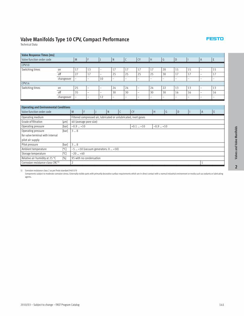
Valve Response Times [ms]
Valve function order code M F J N C CY H G D I A E
CPV10
Switching times on 17 13 – 17 17 17 17 20 15 15 – 15g
off 27 17 – 25 25 25 25 30 17 17 – 17
changeover – – 10 – – – – – – – – –
CPV14
Switching times on 25 – – 24 24 – 24 22 13 13 – 13g
off 35 – – 30 30 – 30 30 16 16 – 16
changeover – – 12 – – – – – – – – –
Operating and Environmental Conditions
Valve function order code M F J N C CY H G D I A E
Operating medium Filtered compressed air, lubricated or unlubricated, inert gases
Grade of filtration [µm] 40 (average pore size)
Operating pressure [bar] –0.9 … +10 +0.1 … +10 –0.9 … +10
Operating pressure
for valve terminal with internal
pilot air supply
[bar] 3 … 8
Pilot pressure [bar] 3 … 8
Ambient temperature [°C] –5 … +50 (vacuum generators: 0 … +50)
Storage temperature [°C] –20 … +40
Relative air humidity at 25 °C [%] 95 with no condensation
Corrosion resistance class CRC1) 2 1
1) Corrosion resistance class 2 as per Festo standard 940 070
Components subject to moderate corrosion stress. Externally visible parts with primarily decorative surface requirements which are in direct contact with a normal industrial environment or media such as coolants or lubricating
agents.
ValvesandValve
Manifolds
2
FAST Program Catalog – Subject to change – 2010/03142
Valve Manifolds Type 10 CPV, Compact PerformanceOrdering Data
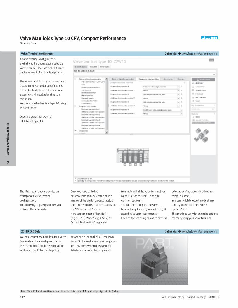
Valve Terminal Configurator Online via:� www.festo.com/us/engineering
A valve terminal configurator is
available to help you select a suitable
valve terminal CPV. This makes it much
easier for you to find the right product.
The valve manifolds are fully assembled
according to your order specifications
and individually tested. This reduces
assembly and installation time to a
minimum.
You order a valve terminal type 10 using
the order code.
Ordering system for type 10
� Internet: type 10
The illustration above provides an
example of a valve terminal
configuration.
The following steps explain how you
arrive at the order code:
Once you have called up
� www.festo.com, select the online
version of the digital product catalog
from the “Products” submenu. Activate
the “Direct Search” menu.
Here you can enter a “Part No.”
(e.g. 18210), “Type” (e.g. CPV14) or
“Article Designation” (e.g. valve
terminal) to find the valve terminal you
want. Click on the link “Configure
common options”.
You can then configure the valve
terminal step by step (from left to right)
according to your requirements.
Click on the shopping basket to save the
selected configuration (this does not
trigger an order).
You can switch to expert mode at any
time by clicking on the “Further
options” link.
This provides you with extended options
for configuring your valve terminal.
2D/3D CAD Data Online via:� www.festo.com/us/engineering
You can request the CAD data for a valve
terminal you have configured. To do
this, perform the product search as de-
scribed above. Enter the shopping
basket and click on the CAD icon (com-
pass). On the next screen you can gener-
ate a 3D preview or request another
data format of your choice by e-mail.
ValvesandValve
Manifolds
2
Lead Time LT for all configurable options on this page: 3D typically ships within 3 days
2010/03 – Subject to change – FAST Program Catalog 143
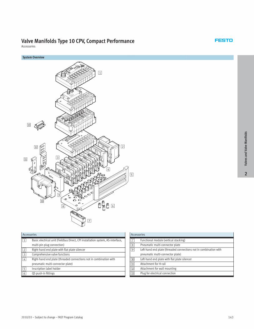
Valve Manifolds Type 10 CPV, Compact PerformanceAccessories
System Overview
9
2
5
4
6
7
8
3
1
aJ
aA
aB
aC
Accessories
1 Basic electrical unit (Fieldbus Direct, CPI installation system, AS-interface,
multi-pin plug connection)
2 Right-hand end plate with flat plate silencer
3 Comprehensive valve functions
4 Right-hand end plate (threaded connections not in combination with
pneumatic multi-connector plate)
5 Inscription label holder
6 QS push-in fittings
Accessories
7 Functional module (vertical stacking)
8 Pneumatic multi-connector plate
9 Left-hand end plate (threaded connections not in combination with
pneumatic multi-connector plate)
aJ Left-hand end plate with flat plate silencer
aA Attachment for H-rail
aB Attachment for wall mounting
aC Plug for electrical connection
ValvesandValve
Manifolds
2

FAST Program Catalog – Subject to change – 2010/03144
ValvesandValve
Manifolds
2
This page intentionally left blank.
2010/03 – Subject to change – FAST Program Catalog 145
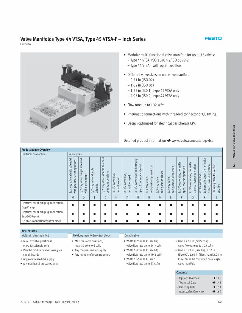
Valve Manifolds Type 44 VTSA, Type 45 VTSA-F – Inch SeriesOverview
• Modular multi-functional valve manifold for up to 32 valves:
– Type 44 VTSA, ISO 15407-2/ISO 5599-2
– Type 45 VTSA-F with optimized flow
• Different valve sizes on one valve manifold:
– 0.71 in (ISO 02)
– 1.02 in (ISO 01)
– 1.65 in (IS0 1), type 44 VTSA only
– 2.05 in (IS0 2), type 44 VTSA only
• Flow rate: up to 102 scfm
• Pneumatic connections with threaded connector or QS fitting
• Design optimized for electrical peripherals CPX
Product Range Overview
Electrical connection Valve types
5/2-way
valve,singlesolenoid
withpneumaticspringreturn
5/2-way
valve,singlesolenoid
withspringreturn
5/2-way
valve,double
solenoid
5/2-way
valve,doublesolenoid
dom
inantswitching
2x3/2-way
valve,
normallyopen
2x3/2-way
valve,
normallyclosed
2x3/2-way
valve:1xnormally
open,1xnormallyclosed
5/3-way
valve,
mid-positionpressurized
5/3-way
valve,
mid-positionclosed
5/3-way
valve,
mid-positionexhausted
2x3/2-way
valve,normally
open,reverse
operation
2x3/2-way
valve,normally
closed,reverse
operation
2x3/2-way
valve:
1xnormallyopen,1xnormally
closed,reverse
operation
Blankingplateforvacant
position
M O J D N K H B G E P Q R L
Electrical multi-pin plug connection,
CageClamp� � � � � � � � � � � � � �
Electrical multi-pin plug connection,
Sub-D (37-pin)� � � � � � � � � � � � � �
Fieldbus connection/control block � � � � � � � � � � � � � �
Key Features
Multi-pin plug manifold Fieldbus manifold/control block Combinable
• Max. 32 valve positions/
max. 32 solenoid coils
• Parallel modular valve linking via
circuit boards
• Any compressed-air supply
• Any number of pressure zones
• Max. 32 valve positions/
max. 32 solenoid coils
• Any compressed-air supply
• Any number of pressure zones
• Width 0.71 in (ISO Size 02):
valve flow rate up to 24.7 scfm
• Width 1.02 in (ISO Size 01):
valve flow rate up to 49.4 scfm
• Width 1.65 in (ISO Size 1):
valve flow rate up to 53 scfm
• Width 2.05 in (ISO Size 2):
valve flow rate up to 102 scfm
• Width 0.71 in (Size 02), 1.02 in
(Size 01), 1.65 in (Size 1) and 2.05 in
(Size 2) can be combined on a single
valve manifold
Contents
– Options Overview � 146
– Technical Data � 148
– Ordering Data � 151
– Accessories Overview � 160
ValvesandValve
Manifolds
2
Detailed product information� www.festo.com/catalog/vtsa

FAST Program Catalog – Subject to change – 2010/03146
Valve Manifolds Type 44 VTSA, Type 45 VTSA-F – Inch SeriesOverview
Flexible Easily Integrated Comprehensive Installation and Maintenance
• Easy modification and expansion due
to high degree of modularity. Fast
connection of the subbases by means
of four screws.
• Fully modular system allows the
combination of 0.71 in (Size 02),
1.02 in (Size 01), 1.65 in (Size 1) and
2.05 in (Size 2) valves on the same
manifold without the need for any
transition/adapter plate.
• Change direction of working ports
with easy-to-install angle plate.
• Fieldbus valve manifold suitable for
CPX electrical peripherals.
• Fieldbus nodes: Interbus, DeviceNet,
Profibus DP, CANopen, CC-Link via
CPX terminal
• Ethernet: Modbus/TCP, EtherNet/IP,
TCP/IP via CPX terminal
• Full complement of CPX I/O modules
• Expandable up to 32 solenoid coils
• Integration of a wide range of function
modules possible
• Supply plates permit a flexible air
supply and variable pressure zones
• High-performance valves in a sturdy
metal housing
• Complete range of vertical sandwich
components such as pressure
regulators, flow control valve,
individual pressure supply, shutoff
plate (hot swap).
• Standard air qualities: 40 micron
filtration grade. Can be used with
lubricated or non-lubricated air, and
inert gases.
• Manual override available, with
momentary, locking, or hidden
(non-accessible) options.
• Ready-to-install unit, preassembled
and tested
• Durable, low cost identification by
label holder on the valve or label
holder on the subbase.
• Secure wall mounting or DIN rail
mounting
• Fast troubleshooting thanks to LEDs
on the valves and diagnosis via
fieldbus.
• Reliability of service thanks to valves
that can be replaced easily and
quickly.
• Easy fault identification using
CPX-MMI handheld diagnostic unit.
Electrical Connection Options
Multi-pin plug connection
Control signals from the controller to
the valve manifold are transmitted via
a pre-assembled multi-core cable or a
self-assembled multi-pin plug
connection (Cage Clamp), which
substantially reduces installation time.
The valve manifolds can be fitted with
max. 32 valves and max. 32 solenoid
coils.
Variants
• Multi-pin plug connection with
manifold strip (Cage Clamp)
24 V DC or 110 V AC
• Pre-assembled connecting cable
24 V DC
• Sub-D plug connector for fitting
by users, 37-pin
Fieldbus connection via the CPX system Fieldbus Variants
An integrated fieldbus node manages
the communication connection to a
higher-order PLC. This enables a
space-saving pneumatic and electronic
solution.
Valve manifolds with fieldbus interfaces
can be configured with up to 16
manifold subbases. With 2 solenoid
coils per connection, up to 32 solenoid
coils can thus be actuated.
• Profibus-DP
• ProfiNet
• Interbus
• DeviceNet connection
• CANopen
• CC-Link
• Ethernet/IP
• EtherCAT
• Front End Controller Remote
• Front End Controller
• Remote I/O
• Modbus/TCP
• Profinet IO
• CPX-Terminal
� www.festo.com/catalog/cpx
Control block connection via the CPX system
Controllers integrated in the Festo
valve manifolds permit the construction
of stand-alone control units to IP65,
without control cabinets.
Using the slave operation mode,
these valve manifolds can be used for
intelligent pre-processing and are
therefore ideal modules for designing
decentralized intelligence.
In the master operation mode, manifold
groups can be designed with many
options and functions, which can
autonomously control a medium-sized
machine/system.
• CPX manifold
� www.festo.com/catalog/cpx
ValvesandValve
Manifolds
2

2010/03 – Subject to change – FAST Program Catalog 147
Valve Manifolds Type 44 VTSA, Type 45 VTSA-F – Inch SeriesOverview
Modular Pneumatic Components
The modular design of the VTSA/VTSA-F
facilitates maximum flexibility right
from the planning stage and offers
maximum ease of service in operation.
The system consists of manifold
subbases and valves.
The manifold subbases are screwed
together and thus form the support
system for the valves.
Inside, the manifold subbases contain
the connection ducts for supplying
compressed air to and venting from the
valve manifold as well as the working
ports for the pneumatic cylinders from
each valve.
Each manifold subbase is connected to
the next using four screws.
Individual manifold sections can be
isolated and further blocks inserted by
loosening these screws. This ensures
that the valve manifold can be rapidly
and reliably expanded.
Modularity in the basic system Modularity in the valves
Modular Electrical Peripherals
The manner in which the valves are
actuated differs according to whether
you are using a multi-pin manifold or
fieldbus manifold.
The VTSA/-VTSA-F with CPX interface is
based on the internal bus system of the
CPX and uses this communication
system for all solenoid coils and a range
of electrical input and output functions.
Parallel linking facilitates the following:
• Transmission of switching
information
• High valve density
• Compact design
• Position-based diagnosis
• Separate voltage supply for valves
• Flexible conversion without address
shifting
• Transmission of status, parameter
and diagnostic data
VTSA with electrical peripherals CPX Modularity with electrical peripherals CPX
ValvesandValve
Manifolds
2

FAST Program Catalog – Subject to change – 2010/03148
Valve Manifolds Type 44 VTSA, Type 45 VTSA-F – Inch SeriesTechnical Data
Flow rate
• Width 0.71 in: Up to 24.7 scfm
• Width 1.02 in: Up to 49.4 scfm
• Width 1.65 in: Up to 53 scfm
• Width 2.05 in: Up to 102 scfm
Valve width
• ISO Size 02: 0.71 in (18 mm)
• ISO Size 01: 1.02 in (26 mm)
• ISO Size 1: 1.65 in (42 mm)
• ISO Size 2: 2.05 in (52 mm)
Voltage
• 24 V DC
• 110 V AC
General Technical Data
Width 0.71 in 1.02 in 1.65 in (type 44 VTSA only) 2.05 in (type 44 VTSA only)
Design Electromagnetically actuated piston spool valve
Lubrication Lubrication for life
Type of mounting Wall mountingyp g
On DIN H-rail to EN 60715
Mounting position Any
Manual override Pushing, pushing/detenting, covered
Pneumatic connections NPT thread
Pneumatic connection Via manifold subbase
Supply port 1 ½ NPT, QS-½-½-U, QS-½-Æ-U ¾NPT, N-¾-P-19-NPT
Exhaust port 3/5 ½ NPT, QS-½-½-U, QS-½-Æ-U ¾NPT, N-¾-P-19-NPT
Working ports 2/4 x NPT,
QS-x-¼-U,
QS-x-Ä-U
¼ NPT,
QS-¼-Ä-U,
QS-¼-y-U
y NPT,
QS-y-y-U,
QS-y-½-U
½ NPT,
QS-½-½-U
Port for external pilot
supply air
14 ¼ NPT
Pilot exhaust air port 12 ¼ NPT
Certification •
Operating and Environmental Conditions
Valve function order code M O J D N K H B G E P Q R
Operating medium Filtered compressed air, lubricated or unlubricated, inert gases
Grade of filtration [µm] 40 (average pore size)
Operating pressure Pilot pressure [psi] 44 … 147p g p
With internal pilot air [psi] 44 … 147
With external pilot air [psi] –13.2 … +147 44 … 147 –13.2 … +147
Ambient temperature [°F] 23 … 122
Temperature of medium [°F] 23 … 122
Storage temperature1) [°F] –4 … +104
Relative air humidity [%] 90
1) Long-term storage
ValvesandValve
Manifolds
2

2010/03 – Subject to change – FAST Program Catalog 149
Valve Manifolds Type 44 VTSA, Type 45 VTSA-F – Inch SeriesTechnical Data
Standard Nominal Flow Rate [scfm] – Type 44 VTSA
Valve function order code M O J D N K H B G E P Q R
Width 0.71 in
Flow rate of valve 26.5 21.2 24.71), 15.22) 21.2
Flow rate of valve on individual subbase 21.2 17.7 19.41), 12.72) 17.7
Flow rate of valve on valve manifold 19.4 14.1 15.91), 10.62) 14.1
Width 1.02 in
Flow rate of valve 49.4 44.1 49.41), 35.32) 44.1
Flow rate of valve on individual subbase 42.4 38.8 42.41), 30.02) 35.3
Flow rate of valve on valve manifold 38.8 31.8 35.31), 24.72) 31.8
Width 1.65 in
Flow rate of valve 63.5 49.4 60.01), 26.52) 49.4
Flow rate of valve on individual subbase 45.9 42.4 42.41), 28.22) 42.4
Flow rate of valve on valve manifold 53.0 42.4 49.41), 28.22) 42.4
Width 2.05 in
Flow rate of valve 141.2 105.9 1271), 602) 105.9
Flow rate of valve on individual subbase 113 88.3 105.91), 602) 88.3
Flow rate of valve on valve manifold 102.4 84.7 98.81), 602) 84.7
1) Switching position
2) Mid-position
Standard Nominal Flow Rate [scfm] – Type 45 VTSA-F
Valve function order code M O J D N K H B G E P Q R
Width 0.71 in
Flow rate of valve 26.5 21.2 17.71), 11.62) 21.2
Flow rate of valve on valve manifold 24.7 19.4 17.71), 11.62) 19.4
Width 1.02 in
Flow rate of valve 49.4 44.1 49.41), 24.72) 44.1
Flow rate of valve on valve manifold 47.7 40.6 47.71), 24.72) 40.6
1) Switching position
2) Mid-position
Valve Response Times [ms]
Valve function order code M O J D N K H B G E P Q R
Width 0.71 in
Response times on 22 12 – – 12 12 12 15 15 15 25 25 25p
off 28 38 – – 30 30 30 44 44 44 12 12 12
changeover – – 11 11 – – – 22 22 22 – – –
Width 1.02 in
Response times on 25 20 – – 20 20 20 22 22 22 32 32 32p
off 45 65 – – 38 38 38 65 65 65 30 30 30
changeover – – 18 18 – – – 33 33 33 – – –
Width 1.65 in (type 44 VTSA only)
Response times on 27 22 – – 20 20 20 22 22 22 34 34 34p
off 45 60 – – 38 38 38 65 65 65 28 28 28
changeover – – 16 16 – – – – – – – – –
Width 2.05 in (type 44 VTSA only)
Response times on 40 20 – – 20 20 20 30 30 30 50 50 50p
off 45 60 – – 35 35 35 100 100 100 65 65 65
changeover – – 18 18 – – – – – – – – –
ValvesandValve
Manifolds
2

FAST Program Catalog – Subject to change – 2010/03150
Valve Manifolds Type 44 VTSA, Type 45 VTSA-F – Inch SeriesTechnical Data
Electrical Data – VTSA/VTSA-F with CPX Manifold
0.71 in 1.02 in 1.65 in (Type 44 VTSA only) 2.5 in (Type 44 VTSA only)
Voltage supply for electronics/sensors (pin 1)
Operating voltage [V] 24 DC ±10%
Steady state current
consumption at 24 V DC
[mA] 20
Duty cycle 100%
Load voltage supply for valves (pin 2)
Operating voltage [V] 24 DC ±10%
Diagnostic message
undervoltage VOFF, load voltage
outside function range
[V] 21.6 … 21.5
Protection class to EN 60529 IP65 (for all types of signal transmission in assembled state)
Power consumption at 24 V DC
2x 3/2-way valve [W] 1.3 4.6
5/2-way valve, 5/3-way valve [W] 1.6 4.6
Electrical Data – VTSA/VTSA-F with Multi-pin Plug Connection
0.71 in 1.02 in 1.65 in (Type 44 VTSA only) 2.05 in (Type 44 VTSA only)
Load voltage supply for valves
Operating voltage [V] 24 DC ±10%
110 AC ±10% (50 … 60 Hz)
Duty cycle 100%
Protection class to EN 60529 IP65 (for all types of signal transmission in assembled state), NEMA 4
Power consumption at 24 V DC
2x 3/2-way valve [W] 1.3 4.6
5/2-way valve, 5/3-way valve [W] 1.6 4.6
Power consumption at 110 V AC
2x 3/2-way valve [VA] 1
5/2-way valve, 5/3-way valve [VA] 1.6
Materials
0.71 in 1.02 in 1.65 in (Type 44 VTSA only) 2.05 in (Type 44 VTSA only)
Manifold subbase Die-cast aluminum
Valve Die-cast aluminum, reinforced polyamide
Seals Nitrile rubber, elastomer (support made of steel)
Supply plate Die-cast aluminum
Right-hand end plate Die-cast aluminum
Left-hand pneumatic interface Die-cast aluminum
Flow control plate Die-cast aluminum
Pressure regulator plate Die-cast aluminum, reinforced polyamide
Multi-pin connection block Die-cast aluminum
Cover for the pneumatic interface and
multi-pin plug connection
Wellamid, reinforced polyamide
ValvesandValve
Manifolds
2

2010/03 – Subject to change – FAST Program Catalog 151
Valve Manifolds Type 44 VTSA, Type 45 VTSA-F – Inch SeriesOrdering Data
Valve Manifold Configurator Online via:� www.festo.com/us/engineering
A valve manifold configurator is avail-
able to help you select a suitable VTSA/
VTSA-F valve manifold. This makes it
much easier for you to find the right
product.
The valve manifolds are fully assembled
according to your order specifications
and are individually tested. This re-
duces the amount of assembly and in-
stallation to a minimum.
You order a valve manifold type 44/45
using the order code.
Ordering system for type 44/45
� Internet: type 44, type 45
Ordering system, CPX
� Internet: cpx
The illustration above provides an
example of a valve manifold
configuration.
The following steps explain how you ar-
rive at the order code:
Once you have called up�
www.festo.com, select the online ver-
sion of the digital product catalog from
the “Products” submenu. Activate the
“Direct Search” menu.
Here you can specify a “Part No.”
(e.g. 539 215 or 539 217), the “Type”
(e.g. VTSA) or “Article name” (e.g. valve
manifold) to find your “Search result”.
Click on the blue shopping basket to
complete the selected product according
to your specifications (this does not
create an order).
You will then be prompted to configure
the product.
Select “Configurator”.
You can then configure the valve mani-
fold step by step (from the top down) ac-
cording to your requirements.
Select the “Finish” menu to continue on
with the ordering process.
2D/3D CAD Data Online via:� www.festo.com/us/engineering
You can request the CAD data for a valve
terminal you have configured. To do
this, perform the product search as de-
scribed above. Enter the shopping
basket and click on the CAD icon (com-
pass). On the next screen you can gener-
ate a 3D preview or request another
data format of your choice by e-mail.
ValvesandValve
Manifolds
2
Lead Time LT for all configurable options on this page: 3D typically ships within 3 days

FAST Program Catalog – Subject to change – 2010/03152
ValvesandValve
Manifolds
2
This page intentionally left blank.

2010/03 – Subject to change – FAST Program Catalog 153
Valve Manifolds Type 44 VTSA, Type 45 VTSA-F – Metric SeriesOverview
• Modular multi-functional valve manifold for up to 32 valves:
– Type 44 VTSA, ISO 15407-2/ISO 5599-2
– Type 45 VTSA-F with optimized flow
• Different valve sizes on one valve manifold:
– 18 mm (ISO 02)
– 26 mm (ISO 01)
– 42 mm (IS0 1), type 44 VTSA only
– 52 mm (IS0 2), type 44 VTSA only
• Flow rate: up to 2,900 l/min
• Pneumatic connections with threaded connector or QS fitting
• Design suitable for electrical peripherals CPX
Product Range Overview
Electrical connection Valve types
5/2-way
valve,singlesolenoid
withpneumaticspringreturn
5/2-way
valve,singlesolenoid
withspringreturn
5/2-way
valve,double
solenoid
5/2-way
valve,doublesolenoid
dom
inantswitching
2x3/2-way
valve,
normallyopen
2x3/2-way
valve,
normallyclosed
2x3/2-way
valve:1xnormally
open,1xnormallyclosed
5/3-way
valve,
mid-positionpressurized
5/3-way
valve,
mid-positionclosed
5/3-way
valve,
mid-positionexhausted
2x3/2-way
valve,normally
open,reverse
operation
2x3/2-way
valve,normally
closed,reverse
operation
2x3/2-way
valve:
1xnormallyopen,1xnormally
closed,reverse
operation
Blankingplateforvacant
position
M O J D N K H B G E P Q R L
Electrical multi-pin plug connection,
CageClamp� � � � � � � � � � � � � �
Electrical multi-pin plug connection,
Sub-D (37-pin)� � � � � � � � � � � � � �
Fieldbus connection/control block � � � � � � � � � � � � � �
Key features
Multi-pin plug manifold Fieldbus manifold/control block Combinable
• Max. 32 valve positions/
max. 32 solenoid coils
• Parallel modular valve linking via
circuit boards
• Any compressed-air supply
• Any number of pressure zones
• Max. 32 valve positions/
max. 32 solenoid coils
• Any compressed-air supply
• Any number of pressure zones
• 18 mm (ISO Size 02): Valve flow rate
up to 550 l/min
• 26 mm (ISO Size 01): Valve flow rate
up to 1,100 l/min
• 42 mm (ISO Size 1):
valve flow rate up to 1,500 l/min
• 52 mm (ISO Size 2):
valve flow rate up to 2,900 l/min
• Width 18 mm (Size 02), 26 mm
(Size 01), 42 mm (Size 1) and 52 mm
(Size 2) can be combined on a single
valve manifold
Contents
– Options Overview � 154
– Technical Data � 156
– Ordering Data � 159
– Accessories Overview � 160
ValvesandValve
Manifolds
2
Detailed product information� www.festo.com/catalog/vtsa
Note: All metric products can be used within inch tubing systems via hybrid fittings (� Overview on page 271)

FAST Program Catalog – Subject to change – 2010/03154
Valve Manifolds Type 44 VTSA, Type 45 VTSA-F – Metric SeriesOverview
Flexible Easily integrated Comprehensive Installation and maintenance
• Easy modification and expansion due
to high degree of modularity. Fast
connection of the subbases by means
of four screws.
• Fully modular system allows the
combination of 18 mm (Size 02),
26 mm (Size 01), 42 mm (Size 1) and
52 mm (Size 2) valves on the same
manifold without the need for any
transition/adapter plate.
• Change direction of working ports
with easy-to-install angle plate.
• Fieldbus valve manifold suitable for
CPX electrical peripherals.
• Fieldbus nodes: Interbus, DeviceNet,
Profibus DP, CANopen, CC-Link via
CPX terminal
• Ethernet: Modbus/TCP, EtherNet/IP,
TCP/IP via CPX terminal
• Full complement of CPX I/O modules
• Expandable up to 32 solenoid coils
• Integration of a wide range of function
modules possible
• Supply plates permit a flexible air
supply and variable pressure zones
• High-performance valves in a sturdy
metal housing
• Complete range of vertical sandwich
components such as pressure
regulators, flow control valve,
individual pressure supply, shutoff
plate (hot swap).
• Standard air qualities: 40 micron
filtration grade. Can be used with
lubricated or non-lubricated air, and
inert gases.
• Manual override available, with
momentary, locking, or hidden
(non-accessible) options.
• Ready-to-install unit, preassembled
and tested
• Durable, low cost identification by
label holder on the valve or label
holder on the subbase.
• Secure wall mounting or DIN rail
mounting
• Fast troubleshooting thanks to LEDs
on the valves and diagnosis via
fieldbus.
• Reliability of service thanks to valves
that can be replaced easily and
quickly.
• Easy fault identification using
CPX-MMI handheld diagnostic unit.
Electrical connection options
Multi-pin plug connection
Control signals from the controller to
the valve manifold are transmitted via
a pre-assembled multi-core cable or a
self-assembled multi-pin plug
connection (Cage Clamp), which
substantially reduces installation time.
The valve manifolds can be fitted with
max. 32 valves and max. 32 solenoid
coils.
Variants
• Multi-pin plug connection with
manifold strip (Cage Clamp)
24 V DC or 110 V AC
• Pre-assembled connecting cable
24 V DC
• Sub-D plug connector for fitting
by users, 37-pin
Fieldbus connection via the CPX system Fieldbus Variants
An integrated fieldbus node manages
the communication connection to a
higher-order PLC. This enables a
space-saving pneumatic and electronic
solution.
Valve manifolds with fieldbus interfaces
can be configured with up to 16
manifold subbases. With 2 solenoid
coils per connection, up to 32 solenoid
coils can thus be actuated.
• Profibus-DP
• ProfiNet
• Interbus
• DeviceNet connection
• CANopen
• CC-Link
• Ethernet/IP
• EtherCAT
• Front End Controller Remote
• Front End Controller
• Remote I/O
• Modbus/TCP
• Profinet IO
• CPX-Terminal
� www.festo.com/catalog/cpx
Control block connection via the CPX system
Controllers integrated in the Festo
valve manifolds permit the construction
of stand-alone control units to IP65,
without control cabinets.
Using the slave operation mode,
these valve manifolds can be used for
intelligent pre-processing and are
therefore ideal modules for designing
decentralized intelligence.
In the master operation mode, manifold
groups can be designed with many
options and functions, which can
autonomously control a medium-sized
machine/system.
• CPX manifold
� www.festo.com/catalog/cpx
ValvesandValve
Manifolds
2
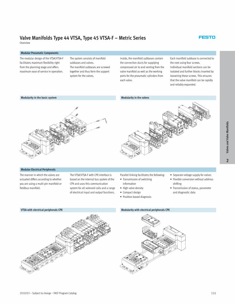
2010/03 – Subject to change – FAST Program Catalog 155
Valve Manifolds Type 44 VTSA, Type 45 VTSA-F – Metric SeriesOverview
Modular Pneumatic Components
The modular design of the VTSA/VTSA-F
facilitates maximum flexibility right
from the planning stage and offers
maximum ease of service in operation.
The system consists of manifold
subbases and valves.
The manifold subbases are screwed
together and thus form the support
system for the valves.
Inside, the manifold subbases contain
the connection ducts for supplying
compressed air to and venting from the
valve manifold as well as the working
ports for the pneumatic cylinders from
each valve.
Each manifold subbase is connected to
the next using four screws.
Individual manifold sections can be
isolated and further blocks inserted by
loosening these screws. This ensures
that the valve manifold can be rapidly
and reliably expanded.
Modularity in the basic system Modularity in the valves
Modular Electrical Peripherals
The manner in which the valves are
actuated differs according to whether
you are using a multi-pin manifold or
fieldbus manifold.
The VTSA/VTSA-F with CPX interface is
based on the internal bus system of the
CPX and uses this communication
system for all solenoid coils and a range
of electrical input and output functions.
Parallel linking facilitates the following:
• Transmission of switching
information
• High valve density
• Compact design
• Position-based diagnosis
• Separate voltage supply for valves
• Flexible conversion without address
shifting
• Transmission of status, parameter
and diagnostic data
VTSA with electrical peripherals CPX Modularity with electrical peripherals CPX
ValvesandValve
Manifolds
2

FAST Program Catalog – Subject to change – 2010/03156
Valve Manifolds Type 44 VTSA, Type 45 VTSA-F – Metric SeriesTechnical Data
Flow rate
• Width 18 mm: Up to 700 l/min
• Width 26 mm: Up to 1,400 l/min
• Width 42 mm: Up to 1,500 l/min
• Width 52 mm: Up to 2,900 l/min
Valve width
• ISO Size 02: 18 mm
• ISO Size 01: 26 mm
• ISO Size 1: 42 mm
• ISO Size 2: 52 mm
Voltage
• 24 V DC
• 110 V AC
General Technical Data
Width 18 mm 26 mm 42 mm (type 44 VTSA only) 52 mm (type 44 VTSA only)
Design Electromagnetically actuated piston spool valve
Lubrication Lubrication for life
Type of mounting Wall mountingyp g
On DIN H-rail to EN 60715
Mounting position Any
Manual override Pushing, pushing/detenting, covered
Pneumatic connections Metric threaded connection
Pneumatic connection Via manifold subbase
Supply port 1 G½, QS-G½-12, QS-G½-16 G¾, N-¾-P-19
Exhaust port 3/5 G½, QS-G½-12, QS-G½-16 G¾, N-¾-P-19
Working ports 2/4 Gx, QS-Gx-6, QS-Gx-8 G¼, QS-G¼-8, QS-G¼-10 Gy, QS-Gy-12, QS-Gy-10 G½ , QS-½-12, QS-½-16
Port for external pilot supply air 14 G¼ G¼ G¼ G¼
Pilot exhaust air port 12 G¼ G¼ G¼ G¼
Certification —
Note: This product conforms with the ISO 1179-1 standard and the ISO 228-1 standard.
Operating and Environmental Conditions
Valve function order code M O J D N K H B G E P Q R
Operating medium Filtered compressed air, lubricated or unlubricated, inert gases
Grade of filtration [µm] 40 (average pore size)
Operating pressure Pilot pressure [bar] 3 … 10p g p
With internal pilot air [bar] 3 … 10
With external pilot air [bar] –0.9 … +10 3 … 10 –0.9 … +10
Ambient temperature [°C] –5 … +50
Temperature of medium [°C] –5 … +50
Storage temperature1) [°C] –20 … +40
Relative air humidity [%] 90
1) Long-term storage
ValvesandValve
Manifolds
2

2010/03 – Subject to change – FAST Program Catalog 157
Valve Manifolds Type 44 VTSA, Type 45 VTSA-F – Metric SeriesTechnical Data
Standard Nominal Flow Rate [l/min] – Type 44 VTSA
Valve function order code M O J D N K H B G E P Q R
Width 18 mm
Flow rate of valve 750 600 7001), 4302) 600
Flow rate of valve on individual subbase 600 500 5501), 3602) 500
Flow rate of valve on valve manifold 550 400 4501), 3002) 400
Width 26 mm
Flow rate of valve 1 400 1 250 1 4001), 1 0002) 1 250
Flow rate of valve on individual subbase 1 200 1 100 1 2001), 8502) 1 000
Flow rate of valve on valve manifold 1 100 900 1 0001), 7002) 900
Width 42 mm
Flow rate of valve 1 800 1 400 1 7001), 7502) 1 400
Flow rate of valve on individual subbase 1 300 1 200 1 2001), 8002) 1 200
Flow rate of valve on valve manifold 1 500 1 200 1 4001), 8002) 1 200
Width 52 mm
Flow rate of valve 4 000 3 000 3 6001), 1 7002) 3 000
Flow rate of valve on individual subbase 3 200 2 500 1 2001), 8002) 2 500
Flow rate of valve on valve manifold 2 900 2 400 2 8001), 1 7002) 2 400
1) Switching position
2) Mid-position
Standard Nominal Flow Rate [l/min] – Type 45 VTSA-F
Valve function order code M O J D N K H B G E P Q R
Width 18 mm
Flow rate of valve 750 600 5001), 3302) 600
Flow rate of valve on valve manifold 700 550 5001), 3302) 550
Width 26 mm
Flow rate of valve 1 400 1 250 1 4001), 7002) 1 250
Flow rate of valve on valve manifold 1 350 1 150 1 3501), 7002) 1 150
1) Switching position
2) Mid-position
Valve Response Times [ms]
Valve function order code M O J D N K H B G E P Q R
18 mm
Response times on 22 12 – – 12 12 12 15 15 15 25 25 25p
off 28 38 – – 30 30 30 44 44 44 12 12 12
changeover – – 11 11 – – – 22 22 22 – – –
26 mm
Response times on 25 20 – – 20 20 20 22 22 22 32 32 32p
off 45 65 – – 38 38 38 65 65 65 30 30 30
changeover – – 18 18 – – – 33 33 33 – – –
42 mm (type 44 VTSA only)
Response times on 27 22 – – 20 20 20 22 22 22 34 34 34p
off 45 60 – – 38 38 38 65 65 65 28 28 28
changeover – – 16 16 – – – – – – – – –
52 mm (type 44 VTSA only)
Response times on 70 25 – – 35 35 35 30 30 30 50 50 50p
off 90 110 – – 70 70 70 100 100 100 65 65 65
changeover – – 18 18 – – – – – – – – –
ValvesandValve
Manifolds
2
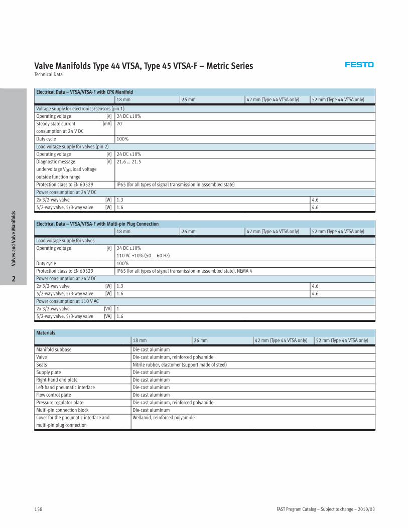
FAST Program Catalog – Subject to change – 2010/03158
Valve Manifolds Type 44 VTSA, Type 45 VTSA-F – Metric SeriesTechnical Data
Electrical Data – VTSA/VTSA-F with CPX Manifold
18 mm 26 mm 42 mm (Type 44 VTSA only) 52 mm (Type 44 VTSA only)
Voltage supply for electronics/sensors (pin 1)
Operating voltage [V] 24 DC ±10%
Steady state current
consumption at 24 V DC
[mA] 20
Duty cycle 100%
Load voltage supply for valves (pin 2)
Operating voltage [V] 24 DC ±10%
Diagnostic message
undervoltage VOFF, load voltage
outside function range
[V] 21.6 … 21.5
Protection class to EN 60529 IP65 (for all types of signal transmission in assembled state)
Power consumption at 24 V DC
2x 3/2-way valve [W] 1.3 4.6
5/2-way valve, 5/3-way valve [W] 1.6 4.6
Electrical Data – VTSA/VTSA-F with Multi-pin Plug Connection
18 mm 26 mm 42 mm (Type 44 VTSA only) 52 mm (Type 44 VTSA only)
Load voltage supply for valves
Operating voltage [V] 24 DC ±10%
110 AC ±10% (50 … 60 Hz)
Duty cycle 100%
Protection class to EN 60529 IP65 (for all types of signal transmission in assembled state), NEMA 4
Power consumption at 24 V DC
2x 3/2-way valve [W] 1.3 4.6
5/2-way valve, 5/3-way valve [W] 1.6 4.6
Power consumption at 110 V AC
2x 3/2-way valve [VA] 1
5/2-way valve, 5/3-way valve [VA] 1.6
Materials
18 mm 26 mm 42 mm (Type 44 VTSA only) 52 mm (Type 44 VTSA only)
Manifold subbase Die-cast aluminum
Valve Die-cast aluminum, reinforced polyamide
Seals Nitrile rubber, elastomer (support made of steel)
Supply plate Die-cast aluminum
Right-hand end plate Die-cast aluminum
Left-hand pneumatic interface Die-cast aluminum
Flow control plate Die-cast aluminum
Pressure regulator plate Die-cast aluminum, reinforced polyamide
Multi-pin connection block Die-cast aluminum
Cover for the pneumatic interface and
multi-pin plug connection
Wellamid, reinforced polyamide
ValvesandValve
Manifolds
2
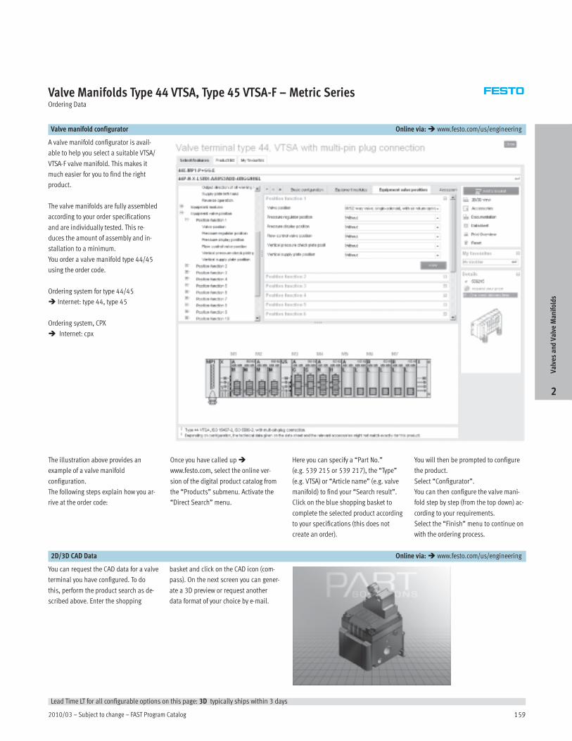
2010/03 – Subject to change – FAST Program Catalog 159
Valve Manifolds Type 44 VTSA, Type 45 VTSA-F – Metric SeriesOrdering Data
Valve manifold configurator Online via:� www.festo.com/us/engineering
A valve manifold configurator is avail-
able to help you select a suitable VTSA/
VTSA-F valve manifold. This makes it
much easier for you to find the right
product.
The valve manifolds are fully assembled
according to your order specifications
and are individually tested. This re-
duces the amount of assembly and in-
stallation to a minimum.
You order a valve manifold type 44/45
using the order code.
Ordering system for type 44/45
� Internet: type 44, type 45
Ordering system, CPX
� Internet: cpx
The illustration above provides an
example of a valve manifold
configuration.
The following steps explain how you ar-
rive at the order code:
Once you have called up�
www.festo.com, select the online ver-
sion of the digital product catalog from
the “Products” submenu. Activate the
“Direct Search” menu.
Here you can specify a “Part No.”
(e.g. 539 215 or 539 217), the “Type”
(e.g. VTSA) or “Article name” (e.g. valve
manifold) to find your “Search result”.
Click on the blue shopping basket to
complete the selected product according
to your specifications (this does not
create an order).
You will then be prompted to configure
the product.
Select “Configurator”.
You can then configure the valve mani-
fold step by step (from the top down) ac-
cording to your requirements.
Select the “Finish” menu to continue on
with the ordering process.
2D/3D CAD Data Online via:� www.festo.com/us/engineering
You can request the CAD data for a valve
terminal you have configured. To do
this, perform the product search as de-
scribed above. Enter the shopping
basket and click on the CAD icon (com-
pass). On the next screen you can gener-
ate a 3D preview or request another
data format of your choice by e-mail.
ValvesandValve
Manifolds
2
Lead Time LT for all configurable options on this page: 3D typically ships within 3 days

FAST Program Catalog – Subject to change – 2010/03160
Valve Manifolds Type 44 VTSA, Type 45 VTSA-FAccessories
System Overview – Valve Manifold with Multi-pin Plug Connection
Order code:
• 44E for the electrical components
• 44P for the pneumatic components
• 45P… for the pneumatic components.
High flow rate with optimized
manifold subbases.
Valve manifolds with multi-pin plug
connection can be expanded with up to
32 valves with max. 32 solenoid coils.
The manifold subbases width 18 and
26 mm are prepared for:
• 2 single solenoid valves
• 2 double solenoid valves
The manifold subbases width 42 mm
are prepared for:
• 1 single solenoid valve
• 1 double solenoid valve
depending on the size.
• Double solenoid valve positions can
be equipped with any valve or a
blanking plate.
• Single solenoid valve positions can
only be equipped with single solenoid
valves or a blanking plate.
The following multi-pin plug
connections to IP65 are available:
• 37-pin Sub-D connection (24 V DC):
The connecting cable can be ordered
in lengths of 2.5 m, 5 m and 10 m for
max. 8, 22 or 32 solenoid coils.
• Manifold strip
(24 V DC or 110 V AC)
2
1
aC
34
5
6
aB aEaD
78
9aJ
aA
aF
aCaG
aE
aH
aI
bJ bA bB
bC
bA
7
bD
bF
bE
bB
bB
bF
bB
bG
bHbB
bFbB
bI
cJcAcB
ValvesandValve
Manifolds
2

2010/03 – Subject to change – FAST Program Catalog 161
Valve Manifolds Type 44 VTSA, Type 45 VTSA-FAccessories
System Overview – Valve Manifold with Multi-pin Plug Connection
Brief description
1 Inscription labels Large, for multi-pin plug connection
2 Multi-core cable –
3 Exhaust plate Ports 3 and 5 separated
4 Fittings For supply plate
5 Silencer For supply plate
6 Exhaust port cover For ducted exhaust air (ports 3 and 5
combined)
7 Duct separation/seal –
8 Manifold subbase For valves with a width of 26 mm
9 Flow control plate –
aJ Vertical supply plate –
aA Vertical shut-off plate –
aB Pressure regulator plate –
aC Cover cap For manual override, pushing, covered
aD Valve Width 26 mm
aE Inscription label holder For valve
aF Blanking plate For unused valve position (vacant position)
aG Valve Width 18 mm
Brief description
aH Valve Width 42 mm (type 44 only)
aI Right-hand end plate –
bJ Silencer For end plate
bA Blanking plugs –
bB Fittings –
bC End plate with pilot air selector –
bD Manifold subbase For valves with a width of 42 mm (type 44
only)
bE Manifold subbase For valves with a width of 18 mm
bF Inscription label holder For supply plate, subbase, 90°
connection plate
bG 90° connection plate –
bH Seals –
bI Silencer –
cJ Supply plate –
cA Multi-pin plug connection Via manifold strip (CageClamp) 24 V DC or110 V AC
cB Multi-pin plug connection With multi-core cable 24 V DC
ValvesandValve
Manifolds
2
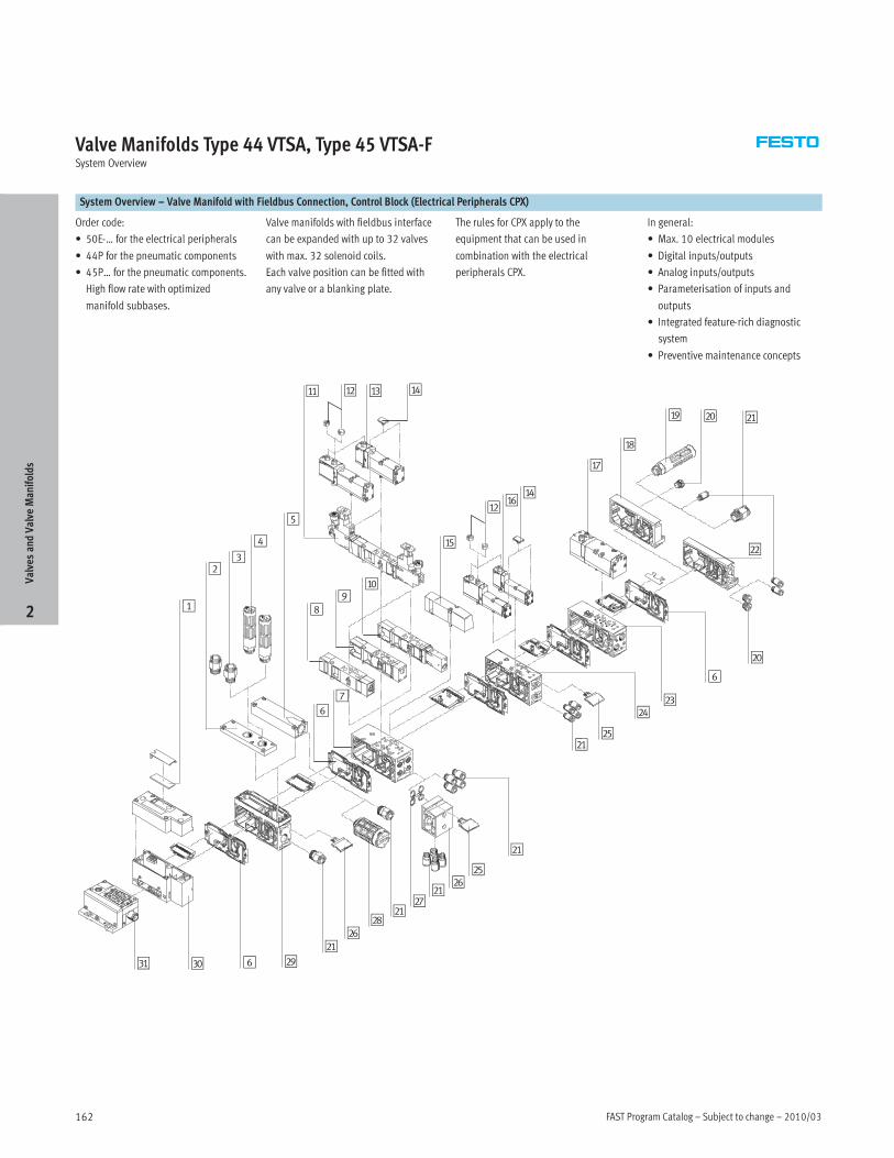
FAST Program Catalog – Subject to change – 2010/03162
Valve Manifolds Type 44 VTSA, Type 45 VTSA-FSystem Overview
System Overview – Valve Manifold with Fieldbus Connection, Control Block (Electrical Peripherals CPX)
Order code:
• 50E-… for the electrical peripherals
• 44P for the pneumatic components
• 45P… for the pneumatic components.
High flow rate with optimized
manifold subbases.
Valve manifolds with fieldbus interface
can be expanded with up to 32 valves
with max. 32 solenoid coils.
Each valve position can be fitted with
any valve or a blanking plate.
The rules for CPX apply to the
equipment that can be used in
combination with the electrical
peripherals CPX.
In general:
• Max. 10 electrical modules
• Digital inputs/outputs
• Analog inputs/outputs
• Parameterisation of inputs and
outputs
• Integrated feature-rich diagnostic
system
• Preventive maintenance concepts
1
aB
23
4
5
aA aDaC
67
89
aJ
aE
aBaF
aD
aG
aH
aI bJ bA
bB
bJ
6
bC
bE
bD
bA
bA
bE
bA
bF
bGbA
bFbA
bH
bI6cJcA
ValvesandValve
Manifolds
2

2010/03 – Subject to change – FAST Program Catalog 163
Valve Manifolds Type 44 VTSA, Type 45 VTSA-FSystem Overview
System Overview – Valve Manifold with Fieldbus Connection, Control Block (Electrical Peripherals CPX)
Brief description
1 Inscription labels Large, for pneumatic interface CPX
2 Exhaust plate Ports 3 and 5 separated
3 Fittings For supply plate
4 Silencer For supply plate
5 Exhaust port cover For ducted exhaust air (ports 3 and 5
combined)
6 Duct separation/seal –
7 Manifold subbase For valves with a width of 26 mm
8 Flow control plate –
9 Vertical supply plate –
aJ Vertical shut-off plate –
aA Pressure regulator plate –
aB Cover cap For manual override, pushing, covered
aC Valve Width 26 mm
aD Inscription label holder For valve
aE Blanking plate For unused valve position (vacant position)
aF Valve Width 18 mm
Brief description
aG Valve Width 42 mm (type 44 only)
aH Right-hand end plate –
aI Silencer For end plate
bJ Blanking plugs –
bA Fittings –
bB End plate with pilot air selector –
bC Manifold subbase For valves with a width of 42 mm (type 44
only)
bD Manifold subbase For valves with a width of 18 mm
bE Inscription label holder For supply plate/subbase/90° connection
plate
bF 90° connection plate –
bG Seals –
bH Silencer –
bI Supply plate –
cJ Pneumatic interface –
cA Fieldbus interface –
ValvesandValve
Manifolds
2

FAST Program Catalog – Subject to change – 2010/03164
ValvesandValve
Manifolds
2
This page intentionally left blank.
Product Range and Company Overview
The Broadest Range of Automation ComponentsWith a comprehensive line of more than 30,000 automation components, Festo is capable of solving the most complexautomation requirements.
Supporting Advanced Automation… As No One Else Can!Festo is a leading global manufacturer of pneumatic and electromechanical systems, components and controls for industrial automation,with more than 12,000 employees in 56 national headquarters serving more than 180 countries. For more than 80 years, Festo hascontinuously elevated the state of manufacturing with innovations and optimized motion control solutions that deliver higher performing,more profitable automated manufacturing and processing equipment. Our dedication to the advancement of automation extends beyondtechnology to the education and development of current and future automation and robotics designers with simulation tools, teachingprograms, and on-site services.
Quality Assurance, ISO 9001 and ISO 14001 Certifications
Festo Corporation is committed to supply all Festo products and services that will meet or exceedour customers’ requirements in product quality, delivery, customer service and satisfaction.
To meet this commitment, we strive to ensure a consistent, integrated, and systematic approachto management that will meet or exceed the requirements of the ISO 9001 standard for QualityManagement and the ISO 14001 standard for Environmental Management.
PLCs and I/O DevicesPLC's, operator interfaces, sensorsand I/O devices
PneumaticsPneumatic linear and rotary actuators,valves, and air supply
ElectromechanicalElectromechanical actuators, motors,controllers & drives
A Complete Suite of Automation ServicesOur experienced engineers provide complete support at every stage of your development process, including: conceptualization,analysis, engineering, design, assembly, documentation, validation, and production.
Complete SystemsShipment, stocking and storage services
Custom Control CabinetsComprehensive engineering supportand on-site services
Custom Automation ComponentsComplete custom engineered solutions
© Copyright 2008, Festo Corporation. While every effort is made to ensure that all dimensions and specifications are correct, Festo cannot guarantee thatpublications are completely free of any error, in particular typing or printing errors. Accordingly, Festo cannot be held responsible for the same. For Liability andWarranty conditions, refer to our “Terms and Conditions of Sale”, available from your local Festo office. All rights reserved. No part of this publication may bereproduced, distributed, or transmitted in any form or by any means, electronic, mechanical, photocopying or otherwise, without the prior written permission ofFesto. All technical data subject to change according to technical update.
Printed on recycled paper at New Horizon Graphic, Inc., FSC certified as an environmentally friendly printing plant.

Cata
log
no.:
1308
2088
04.2
010
Festo Regional Contact Center5300 Explorer DriveMississauga, Ontario L4W 5G4Canada
USA Customers:
For ordering assistance,Call: 1.800.99.FESTO (1.800.993.3786)Fax: 1.800.96.FESTO (1.800.963.3786)Email: [email protected]
For technical support,Call: 1.866.GO.FESTO (1.866.463.3786)Fax: 1.800.96.FESTO (1.800.963.3786)Email: [email protected]
Canadian Customers:
Call: 1.877.GO.FESTO (1.877.463.3786)Fax: 1.877.FX.FESTO (1.877.393.3786)Email: [email protected]
USA HeadquartersFesto Corporation395 Moreland RoadP.O. Box 18023Hauppauge, NY 11788, USAwww.festo.com/us
USA Sales Offices
AppletonNorth 922 Tower View Drive, Suite NGreenville, WI 54942, USA
Boston120 Presidential Way, Suite 330Woburn, MA 01801, USA
Chicago1441 East Business Center DriveMt. Prospect, IL 60056, USA
Dallas1825 Lakeway Drive, Suite 600Lewisville, TX 75057, USA
Detroit – Automotive Engineering Center2601 Cambridge Court, Suite 320Auburn Hills, MI 48326, USA
New York395 Moreland RoadHauppauge, NY 11788, USA
Silicon Valley4935 Southfront Road, Suite FLivermore, CA 94550, USA
Festo North America
United States
Western USAFesto Corporation4935 Southfront Road,Suite FLivermore, CA 94550, USAPhone: 1.925.371.1099Fax: 1.925.245.1286
Central USAFesto Corporation1441 East BusinessCenter DriveMt. Prospect, IL 60056, USAPhone:1.847.759.2600Fax: 1.847.768.9480
Festo WorldwideArgentina Australia Austria Belarus Belgium Brazil Bulgaria Canada Chile China Colombia Croatia Czech Republic Denmark Esto-
nia Finland France Germany Great Britain Greece Hong Kong Hungary India Indonesia Iran Ireland Israel Italy Japan Latvia Lithua-
nia Malaysia Mexico Netherlands New Zealand Norway Peru Philippines Poland Romania Russia Serbia Singapore Slovakia
Slovenia South Africa South Korea Spain Sweden Switzerland Taiwan Thailand Turkey Ukraine United States Venezuela
www.festo.com
USA Headquarters, East: Festo Corp., 395 Moreland Road, Hauppauge, NY 11788Phone: 1.631.435.0800; Fax: 1.631.435.8026;Email: [email protected] www.festo.com/us
Headquarters: Festo Pneumatic, S.A., Av. Ceylán 3, Col. Tequesquinahuac,54020 Tlalnepantla, Edo. de MéxicoPhone:011 52 [55] 53 21 66 00; Fax: 011 52 [55] 53 21 66 65;Email: [email protected] www.festo.com/mx
Canada
Mexico
Headquarters: Festo Inc., 5300 Explorer Drive, Mississauga, Ontario L4W 5G4Phone: 1.905.624.9000; Fax: 1.905.624.9001;Email: [email protected] www.festo.ca