Embed Size (px)
Citation preview
the Technology Interface/Fall 2007 Howard, Meixell, Montelongo, Sturhan, Patil, Attarzadeh
1
Endless Coffee Pot
by
Lee Howard Brian Meixell Juan Montelongo [email protected] [email protected] [email protected] Brian Sturhan Manmeet B. Patil Dr. Farrokh Attarzadeh [email protected] [email protected] [email protected] Teaching Assistant Project Advisor
Department of Engineering Technology
University of Houston
ABSTRACT
This paper describes a one-semester long senior project by four senior students in Computer Engineering Technology program. The paper details the design and implementation of a coffee maker that would continuously replenish its supply of freshly brewed coffee, requiring little or no user interaction. The product is designed in such a way that is appealing to both residential and commercial markets and could also be marketed as a tea maker. The user would enter the current time, start time, interval of operation and stop time. The other tasks that would require user maintenance would be the loading of coffee pouches into the dispenser and unloading used pouches from the waste receptacle. The core component of the entire product is a “run-of-the-mill” Proctor Silex coffee maker [1] which performs the basic brewing process. The brain of the product is Mini-Max/51C-2 8051 microcontroller board manufactured by BiPOM Electronics [2] and interfaces with all sensors, pumps, and motors through the Custom-Built Integration Board (CBIB). The CBIB connects the prototype’s components to the BiPOM 8051 microcontroller. The CBIB was designed and constructed using EAGLE (Easily Applicable Graphical Layout Editor) for Windows [3]. Patent application for the Endless Coffee Pot was filed through the University of Houston, office of Intellectual Property Management [4].
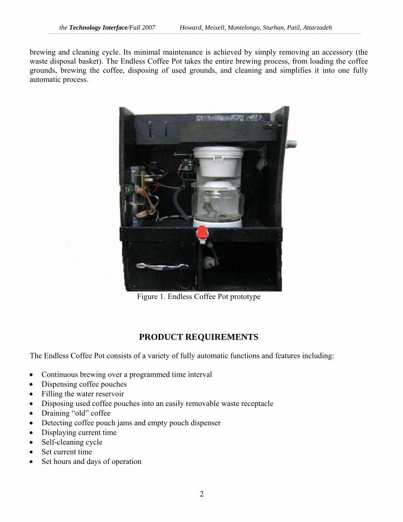
INTRODUCTION The trend in coffee maker manufacturing is turning to a simpler, more user-friendly environment that involves minimal maintenance. The less expensive coffee makers on the market are using single-serve coffee pots, while high-end models, like the Keurig Platinum B70 [5], utilize a steam brewing process and have integrated the filter and grounds into single-serve miniature packages. The Endless Coffee Pot (Figure 1) embraces these ideas and expands on them using the modern day technology. It accomplishes the core functionality by brewing 12-cup coffee pouch every cycle and thus, effectively eliminating the need for single-serve pouches. It is user-friendly and allows for a small number of inputs to initialize the
the Technology Interface/Fall 2007 Howard, Meixell, Montelongo, Sturhan, Patil, Attarzadeh
2
brewing and cleaning cycle. Its minimal maintenance is achieved by simply removing an accessory (the waste disposal basket). The Endless Coffee Pot takes the entire brewing process, from loading the coffee grounds, brewing the coffee, disposing of used grounds, and cleaning and simplifies it into one fully automatic process.
Figure 1. Endless Coffee Pot prototype
PRODUCT REQUIREMENTS The Endless Coffee Pot consists of a variety of fully automatic functions and features including: • Continuous brewing over a programmed time interval • Dispensing coffee pouches • Filling the water reservoir • Disposing used coffee pouches into an easily removable waste receptacle • Draining “old” coffee • Detecting coffee pouch jams and empty pouch dispenser • Displaying current time • Self-cleaning cycle • Set current time • Set hours and days of operation

the Technology Interface/Fall 2007 Howard, Meixell, Montelongo, Sturhan, Patil, Attarzadeh
3
• Set time coffee is considered fresh • Start a manual brew cycle
BLOCK DIAGRAM OF THE ENDLESS COFFEE POT
The block diagram in Figure 2 shows the input/output processes of the Endless Coffee Pot. The functional descriptions of the major components involved in these processes are: Basic coffee machine – The core component of the entire Endless Coffee Pot is a “run-of-the-mill” Proctor Silex coffee maker. It will perform the basic brewing process. Mini-Max/51-C2 8051 Microcontroller – The 8051 microcontroller is the brain of the product. It interfaces with all sensors, pumps, and motors through the CBIB. It directly communicates with the LCD screen and keypad. The microcontroller also carries out all program commands. Custom-Built Integration Board – This board connects all of the prototype’s components to the BiPOM 8051 microcontroller. LCD screen – The LCD screen displays messages and menus to the user. The user can visually verify the settings they have programmed into the coffee maker by way of the LCD screen. Keypad – The keypad allows the user to program various settings on the coffee maker. All user input is through the keypad. Water Reservoir Solenoid – The water reservoir solenoid transfers water from the water source into the water reservoir. Water Reservoir Level Switch – The water reservoir level switch sends a signal to the microcontroller when the water inside the water reservoir reaches a predetermined level. Coffee Reservoir – The coffee reservoir holds and keeps the freshly brewed coffee warm until dispensed. Coffee Reservoir Level Switch - The coffee reservoir level switch sends a signal to the microcontroller when the coffee in the reservoir drops below a predetermined level.

the Technology Interface/Fall 2007 Howard, Meixell, Montelongo, Sturhan, Patil, Attarzadeh
4
Figure 2. Block Diagram of the Endless Coffee Pot
Coffee Reservoir Drain Pump - The coffee reservoir drain pump empties the contents of the coffee reservoir when a signal is received from the microcontroller. Coffee Pouch Dispenser – The coffee pouch dispenser holds and dispenses pre-packaged coffee pouches. It holds up to ten individual pouches. Coffee Pouch Dispenser Switch – The coffee pouch dispenser switch sends a signal to the microcontroller when a coffee pouch has passed by it on its way to the filter basket.
the Technology Interface/Fall 2007 Howard, Meixell, Montelongo, Sturhan, Patil, Attarzadeh
5
Filter Dump Servo Motor – The filter dump servo motor rotates the filter basket completely upside down to dump out the used coffee pouch. Filter Change Arm Servo Motor – The filter change arm servo motor swings out the robotic arm to place the filter basket directly underneath the coffee pouch dispenser. Heating Element Switch – The heating element switch turns on/off the heating element when it receives a signal from the microcontroller.
DESIGN DESCRIPTION
Some of the components have been described in the block diagram shown in Figure 2. The purpose of each component is briefly described below.
8-Relay Board – switches power to each of the components Filter Basket Changing Arm – allows unloading and loading of the coffee pouches Servo Motors – move the filter changing arm and turn over the filter basket Custom-made Coffee Pouch – has exact amount of coffee grounds to brew 12 cups of coffee Pouch Dispenser (helical coil and motor) – dispenses a coffee pouch into the filter basket when it is activated Pouch Dispenser Access Door – allows user access to refill the pouch dispenser once it is empty Solenoid Valve – fills the water reservoir with water, via vinyl tubing, when it is activated Water Reservoir Level Sensor – deactivates the solenoid valve whenever a certain water level is attained Coffee Reservoir Level Sensor – activates a brewing cycle whenever the coffee falls below a certain level Safety Spigot – dispenses coffee from the coffee reservoir, while preventing accidental release Coffee Reservoir Plumbing – directs coffee to the safety spigot and also to the drain pump Water Reservoir Plumbing – channels water into the prototype’s water reservoir Waste Receptacle – collects the used coffee pouches; can be removed to throw away used coffee pouches Appliance Cabinet – houses the entire product
The Futaba S3004 [6] servos are controlled by pulse width modulation. The code in this section is written in assembly to provide an accurate pulse. The pulse width has to be between approximately 1ms and 2ms to properly control the servo’s positions. The pulse width for these servos was determined experimentally. A 2ms pulse was found using an oscilloscope and then the values in the assembly code were adjusted to bring the servos to their proper positions. An approximately 1ms pulse width is necessary to swing the arm out and about 1.5ms to swing the arm back into the coffee maker. The filter basket has to rotate 180 degrees to dispose the used filter pouches. An approximately 1ms pulse width turns the filter basket over and 2ms brings it back to the upright position.

the Technology Interface/Fall 2007 Howard, Meixell, Montelongo, Sturhan, Patil, Attarzadeh
6
It was necessary to test the CBIB and its connection to all the components in the system. The CBIB is the connection between the microcontroller and all components. The servos also had to be tested to make sure they could swing with the proper range of motion. The length of the pulses needed to be calibrated to ensure that the servos would swing to the correct position. Since some of the components in the system required 120VAC, relays were needed to control them. The microcontroller had to be able to apply voltage to transistors which supply 24VDC to the relays connected to the 120VAC components. These had to be accurate and could not arbitrarily turn on the relays, since that could cause water to flood the system. The switches in the system were also tested to insure that the microcontroller could sense a change in state. This was of particular importance in the case of the water reservoir. If the microcontroller does not know that the reservoir is full it will not shut off the solenoid valve and the system will flood. To take into consideration the real time events that might take place, it was necessary to test some time dependent elements in the system. The length of time it would take to brew a pot of coffee had to be tested to ensure that it did not try and brew another pot in the middle of a brew cycle. The time it would take to dispense one pouch from the beginning of the dispenser had to be tested to implement a refill function.
SOFTWARE FLOWCHART OF ENDLESS COFFE POT
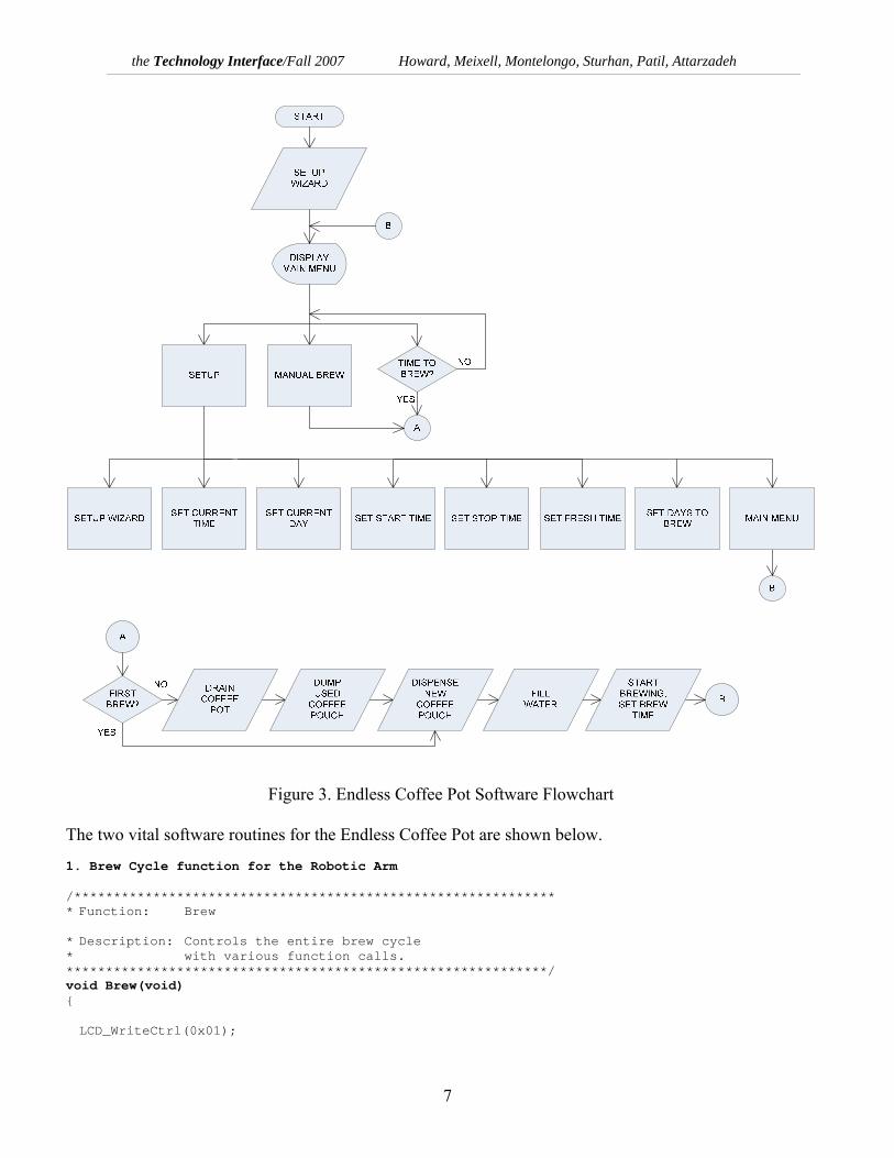
A real time clock was designed to keep track of start and stop times. This was done using a timer interrupt routine provided through the BiPOM sample code. In this code, the HEX value C4 is reloaded into the counter register hi-byte TH0 every time the interrupt occurs. The counter register TH0 counts down 15,359 times every interrupt cycle. At a clock speed of 22.1184MHz, an interrupt occur every 8.33ms. The interrupt increments a variable 120 times and then increments one second since 8.33ms * 120 ≈ 1s. The flowchart in Figure 3 shows various sequences needed for a safe operation of the Endless Coffee Pot.
the Technology Interface/Fall 2007 Howard, Meixell, Montelongo, Sturhan, Patil, Attarzadeh
7
Figure 3. Endless Coffee Pot Software Flowchart
The two vital software routines for the Endless Coffee Pot are shown below. 1. Brew Cycle function for the Robotic Arm /************************************************************* * Function: Brew * Description: Controls the entire brew cycle * with various function calls. *************************************************************/ void Brew(void) LCD_WriteCtrl(0x01);

the Technology Interface/Fall 2007 Howard, Meixell, Montelongo, Sturhan, Patil, Attarzadeh
8
LCD_printf ("Brewing In Progress..."); LCD_WriteCtrl(0xC0); LCD_printf ("Enjoy Your Coffee!"); OpenArm(); //check for first brew. If not, do this. if(!FirstBrew) setbit(Drain); while (1) if(tstbit(P3,4)) //wait for pot level to drop delay(10000); //time to drain below one cup. clrbit (Drain); break; DumpBasket(); DispensePacket(); LCD_WriteCtrl(0x01); LCD_printf ("Brewing In Progress..."); LCD_WriteCtrl(0xC0); LCD_printf ("Enjoy Your Coffee!"); CloseArm(); setbit (Solenoid); while (1) if(!tstbit(P3,6)) //wait for reservoir to fill clrbit (Solenoid); break; //Start Brewing. setbit (Heat); time.BrewTimeHour = time.Hour; time.BrewTimeMinute = time.Minute; //delay while coffee brews while((time.Minute - time.BrewTimeMinute) < BrewTime) //Do nothing. Allow pot to brew. FirstBrew = 0; //Ensures the main menu is displayed when returning from Brew() since //it stays in ScanKeypadMenu() until a button is pushed. LCD_WriteCtrl(0x01); LCD_printf ("MAIN MENU"); LCD_WriteCtrl(0xC0); LCD_printf ("1. Setup... v"); return;
the Technology Interface/Fall 2007 Howard, Meixell, Montelongo, Sturhan, Patil, Attarzadeh
9
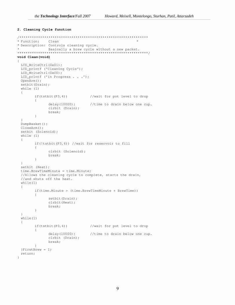
2. Cleaning Cycle function /************************************************************** * Function: Clean * * Description: Controls cleaning cycle. * Basically a brew cycle without a new packet. ***************************************************************/ void Clean(void) LCD_WriteCtrl(0x01); LCD_printf ("Cleaning Cycle"); LCD_WriteCtrl(0xC0); LCD_printf ("in Progress . . ."); OpenArm(); setbit(Drain); while (1) if(tstbit(P3,4)) //wait for pot level to drop delay(10000); //time to drain below one cup. clrbit (Drain); break; DumpBasket(); CloseArm(); setbit (Solenoid); while (1) if(!tstbit(P3,6)) //wait for reservoir to fill clrbit (Solenoid); break; setbit (Heat); time.BrewTimeMinute = time.Minute; //Allows the cleaning cycle to complete, starts the drain, //and shuts off the heat. while(1) if(time.Minute > (time.BrewTimeMinute + BrewTime)) setbit(Drain); clrbit(Heat); break; while(1) if(tstbit(P3,4)) //wait for pot level to drop delay(10000); //time to drain below one cup. clrbit (Drain); break; FirstBrew = 1; return;

the Technology Interface/Fall 2007 Howard, Meixell, Montelongo, Sturhan, Patil, Attarzadeh
10
HARDWARE & CONSTRUCTION DETAILS The core component of the entire project is a Proctor-Silex coffee maker. The filter basket of the coffee maker is attached to a robotic arm consisting of two Futaba S3004 servo motors. One servo motor is attached to a hollow, aluminum shaft. Both are mounted to a piece of sheet metal shaped to create support for the filter basket and allow the servo to turn the shaft. Another piece of sheet metal is designed to be an arm for mounting another servo to connect to the filter basket. This arm is connected to the aforementioned shaft to rotate the filter basket in and out of the coffee machine. The servo mounted to the arm dumps the filter basket and returns it to the upright position (Figures 4 and 5) to be refilled and returned to the brew position.
Figure 4. Coffee maker with robotic arm Figure 5. Coffee maker as mounted in the cabinet The plumbing of the entire system consists of vinyl tubing, drain pump, solenoid valve, safety spigot and Quick-Connect fittings (Figure 6). To accommodate draining of the coffee reservoir, a hole had to be drilled into the coffee pot continuing through the entire coffee maker base (Figure 7). The coffee pot is connected to the safety spigot and drain pump via 3/8” vinyl tubing and a T-connector. A drain hose (3/8” vinyl tubing) leads from the drain pump to user designated drain. The solenoid valve and water reservoir are connected by 1/2” vinyl tubing and a connector. The connector is mounted through a hole drilled through the side of the water reservoir 1/2” from the bottom of the reservoir.
the Technology Interface/Fall 2007 Howard, Meixell, Montelongo, Sturhan, Patil, Attarzadeh
11
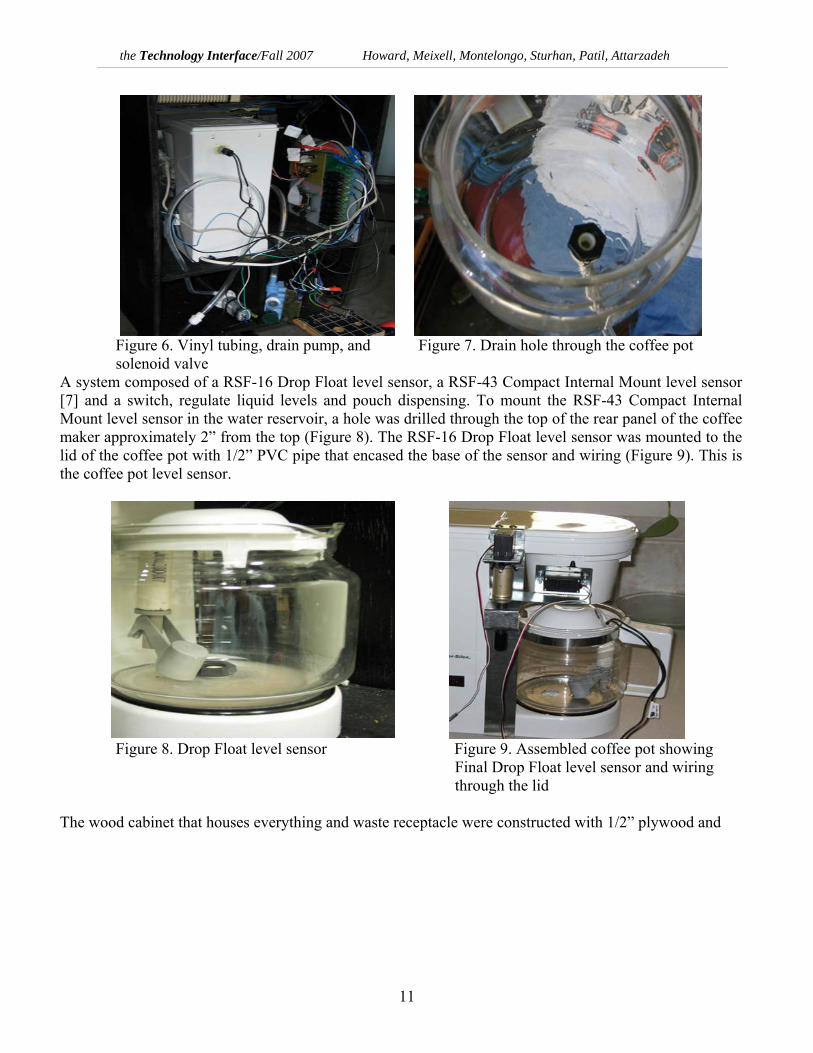
Figure 6. Vinyl tubing, drain pump, and Figure 7. Drain hole through the coffee pot solenoid valve A system composed of a RSF-16 Drop Float level sensor, a RSF-43 Compact Internal Mount level sensor [7] and a switch, regulate liquid levels and pouch dispensing. To mount the RSF-43 Compact Internal Mount level sensor in the water reservoir, a hole was drilled through the top of the rear panel of the coffee maker approximately 2” from the top (Figure 8). The RSF-16 Drop Float level sensor was mounted to the lid of the coffee pot with 1/2” PVC pipe that encased the base of the sensor and wiring (Figure 9). This is the coffee pot level sensor.
Figure 8. Drop Float level sensor Figure 9. Assembled coffee pot showing Final Drop Float level sensor and wiring through the lid The wood cabinet that houses everything and waste receptacle were constructed with 1/2” plywood and

the Technology Interface/Fall 2007 Howard, Meixell, Montelongo, Sturhan, Patil, Attarzadeh
12
Figure 10. Cabinet breakdown showing all views and pictorial view
wood screws. The sections are cut and assembled according to Figure 10. The assembled housing and waste receptacle were painted with flat black spray paint. A handle was placed on the front of the waste receptacle. Coffee pouches are dispensed into the filter basket by way of a helical coil and product motor from a vending machine [8]. The product motor consists of a DC motor interfaced with a matched gearbox. The helical coil was recessed into the cabinet to allow for proper connection to the motor Figure 11). The
Figure 11. Helical coil with coffee pouches

the Technology Interface/Fall 2007 Howard, Meixell, Montelongo, Sturhan, Patil, Attarzadeh
13
Figure 12. Final prototype showing the left view, right view and front view
housing for the coil is made of 1/2” plywood and is lined with smooth tape to reduce the likelihood of pouches binding against the housing. The housing is mounted in the cabinet (see Figure 12 for specific placement). The CBIB is designed and constructed using EAGLE [2]. A schematic of the circuit was drawn and a board layout was made. Then EAGLE was used to find the best route for all circuit traces based on the user’s specifications. Once completed, the circuit was printed using a laser printer and ironed onto a copper board. The board was then soaked in chemicals to remove the excess copper, leaving only the circuit traces. Holes were drilled for the components and the components were soldered onto the board. This board is the interface between all the components in the system and the BiPOM microcontroller [1]. The following components make up the CBIB: • (4) 20kΩ Resistors • (4) 2N2222 Transistors • (3) 220Ω Resistors • Pin connectors for ribbon cable and servos • Power connectors for switches and relay board The relay board has eight (8) 24V relays that can be controlled by parallel signals to each relay. They are used to switch on the 120VAC components on the coffee pot (heating element, solenoid, and drain pump). 120VAC is connected directly to this board and when a relay closes, it allows 120VAC to pass to the items mentioned above. One of the relays has been modified to allow 24VDC to power the pouch dispenser motor. All this is controlled by the microcontroller through the CBIB.

the Technology Interface/Fall 2007 Howard, Meixell, Montelongo, Sturhan, Patil, Attarzadeh
14
Figure 13 shows the major components mounted on a 9.5” x 9.5” x 0.25” on a sheet of plastic. Figure 14 shows the final installation of the BiPOM board, control board, and relay board in the coffee maker. All the electrical components were connected with 24 AWG wires, except for the power adapters and main power cord which use 16 AWG wire.
Figure 13. (Counter-clockwise from left) 8-Relay board, Figure 14. Final connection of the keypad, CBIB, and BiPOM 8051 microcontroller mounted on LCD, CBIB, Relay board, and BiPOM a plastic board Microcontroller
FUTURE WORK
There Endless Coffee Pot can be improved in may ways. High impact plastic cabinet can be used for more durable product and there can be present a large touch screen for user interaction. Additional utilities like Calendar function could be added. There can be changes in display where Coffee “age” can be displayed on main menu. This will always get the user the status of the present coffee. Also there can be much more variations for different beverages. The product can be extended for multiple types of drinks in order to appeal to various types of masses. The only major problem encountered was the uniform production of the coffee pouches. The coffee pouches were hand-made using two filters sewn together. This process did not allow all coffee pouches to be of the same size. Some of the coffee pouches were too big, thus causing them to bind on the outer edges of the coffee pouch dispenser. Other coffee pouches were too small to activate the dispenser switch, which signals the microcontroller to turn off the product motor. Mass production of the coffee pouches would completely eliminate this problem. This is an area where there can be improvement.

the Technology Interface/Fall 2007 Howard, Meixell, Montelongo, Sturhan, Patil, Attarzadeh
15
CONCLUSIONS The Endless Coffee Pot would bring about a plethora of satisfying results to the coffee maker market because of its capacity to be applied to a vast number of industries. An industry that would reap the benefits of such a product would be the fast food industry. The reason is that The Endless Coffee Pot, with minor adjustments, could be incorporated into existing commercial systems, effectively reducing the wait time for customers who quickly need a cup of coffee. Another industry that would gain from the product would be the residential appliance industry. The Endless Coffee Pot would be able to provide a hot cup of coffee to employees that are always in a hurry to get from their residence to their place of business. It would eliminate the need for them to get up early, load a coffee pouch, fill the reservoir with water, and wait for the brew cycle to complete. The coffee maker will keep the coffee ready at pre-defined time. The Endless Coffee Pot will eliminate all of these problems by initiating at a set time, filling the reservoir with water, loading the coffee pouch, and completing the brew cycle – all before the user even thinks about going to the kitchen. Small offices would also benefit as a result of this product. The Endless Coffee Pot would eliminate the need for a person to refill all necessary items for a brew cycle each time the coffee finishes. This product has the potential to provide the American and international coffee maker markets with good demand as this coffee maker will find application not only in corporate world but also in household activities.
REFERENCES
[1] Hamilton Beach/Proctor-Silex, Inc. http://www.proctorsilex.com/cgi-bin/main/co_disp/displ/pgname/company/strfnbr/21 [Accessed September 17, 2007] [2] BiPOM Electronics, Inc. Mini-Max/51-C2 Technical Manual, http://www.bipom.com/documents/boards/minimax51c2.pdf [Accessed September 17, 2007] [3] Eagle PCB layout software, http://www.cadsoftusa.com [Accessed September 17, 2007] [4] Office of Intellectual Property Management, http://www.research.uh.edu/Departments/Intellectual_Property_Management, [Accessed September 17, 2007] [5] Keurig Coffee maker, http://www.keurig.com/b70.asp, [Accessed September 17, 2007] [6] Servo Control and Interfacing http://www.seattlerobotics.org/encoder/200106/16csscnt.htm [Accessed September 17, 2007] [7] Level Sensors, http://crydom.com/ [Accessed September 17, 2007] [8] TECHNIVEND vending machine supplies, http://www.technivend.com [Accessed September 17, 2007]