Embed Size (px)
Citation preview

Gibbs and Associates323 Science Drive
Moorpark, CA 93021(805) 523-0004
March, 1999
SOLIDSURFACERADDENDUM
FANUC Replacements

� S o l i d S u r f a c e r A d d e n d u m G F K - 1 7 1 0
Proprietary NoticeThis document contains propriety information of Gibbs and Associates and is to be used only pur-suant to and in conjunction with the license granted to the licensee with respect to the accompany-ing Gibbs and Associates licensed software. Except as expressly permitted in the license, no part ofthis document may be reproduced, transmitted, transcribed, stored in a retrieval system, or translatedinto any language or computer language, in any form or by any means, electronic, magnetic, optical,chemical, manual or otherwise, without the prior expressed written permission from Gibbs andAssociates or a duly authorized representative thereof.
It is strongly advised that users carefully review the license in order to understand the rights andobligations related to this licensed software and the accompanying documentation.
Use of the computer software and the user documentation has been provided pursuant to a Gibbsand Associates licensing agreement.
© Copyright 1999 Gibbs and Associates, Inc.All Rights Reserved
Acknowledgements:Written by Wil GaffgaThanks to Bill Gibbs, Shannon McConville, Steve Aughinbaugh, Bart Ehlers, Gary Esser, IsraelKlain, Alvaro Martins and Vincent Schmidt for their input, advice and assistance.
Trademarks:Windows NT and Windows 95 are trademarks of Microsoft Corporation
Printed in the United States of America

Table of ContentsINTRODUCTION 1
INTERFACE 1File Extension Preferences . . . . . . . . . . . . . . . . . . . . . . . . . . . . . . . . . . . . . . . . . . . . . . . . . . .1Select Sub-Menu . . . . . . . . . . . . . . . . . . . . . . . . . . . . . . . . . . . . . . . . . . . . . . . . . . . . . . . . . .1
MODELING 2Sweep Dialog . . . . . . . . . . . . . . . . . . . . . . . . . . . . . . . . . . . . . . . . . . . . . . . . . . . . . . . . . . . . . . . 2
DATA EXCHANGE 5Direct Open of Native File Formats . . . . . . . . . . . . . . . . . . . . . . . . . . . . . . . . . . . . . . . . . . . . . 5IGES Surface Export . . . . . . . . . . . . . . . . . . . . . . . . . . . . . . . . . . . . . . . . . . . . . . . . . . . . . . . . . 6Improved SAT Import . . . . . . . . . . . . . . . . . . . . . . . . . . . . . . . . . . . . . . . . . . . . . . . . . . . . . . . . . 6
MACHINING 8CAM Engine Tab . . . . . . . . . . . . . . . . . . . . . . . . . . . . . . . . . . . . . . . . . . . . . . . . . . . . . . . . . . . . 8Surfacing Operations . . . . . . . . . . . . . . . . . . . . . . . . . . . . . . . . . . . . . . . . . . . . . . . . . . . . . .122.5D Material Only . . . . . . . . . . . . . . . . . . . . . . . . . . . . . . . . . . . . . . . . . . . . . . . . . . . . . . .16Machining Open Sided Pockets . . . . . . . . . . . . . . . . . . . . . . . . . . . . . . . . . . . . . . . . . . . . . .11
SOLIDSURFACER TUTORIAL NOTES 20
MACHINING EXERCISES 21Exercise #1 : Phone . . . . . . . . . . . . . . . . . . . . . . . . . . . . . . . . . . . . . . . . . . . . . . . . . . . . . . .21
G F K - 1 7 1 0 T a b l e o f C o n t e n t s �
1
FANUC Replacements

IntroductionThis addendum details the additions to the system contained within v. 5.0. It is solely a supplementto the SolidSurfacer manual. This addendum does not include Geometry Creation, Lathe, Mill,Rotary Mill or Advanced Milling functionality.
InterfaceThis section describes the changes to the interface. The system has adopted modifications to theSelect sub-menu and an expanded File Extension preference.
F ILE EXTENSION PREFERENCESThe File Extension Preference has been modified to includeSolidEdge and SolidWorks files. This is to accommodate the newcapability of directly opening these files. (See the Data Exchangesection of this document for more information.)
SELECT SUB-MENUThe user may now automatically select all edgeson an active body. This capability is accessed fromthe Select sub-menu of the Edit menu. Any edgesthat the user does not wish to have active may thenbe de-selected.
2
� S o l i d S u r f a c e r A d d e n d u m G F K - 1 7 1 0

ModelingThis section describes the changes to modeling functions in the SolidSurfacer module.
SWEEP DIALOG
Drive Curve (DC) Blend: The user is given control over transitions between Drive Curves. Used whenthere are more than two Drive Curves.
Linear Blends will produce the same result as if the sweep was performed on the sections sepa-rately. As if the results of a sweep between DC1 and DC2 were added to the results of a sweepbetween DC2 and DC3.Smooth Blends: A smooth continuous body will be swept between the drive curves as specifiedby the option selected.
No Tangent Control: There will simply be a smooth transition between Drive Curves. Theuser has no control over tangency.Tangent at End DCs: The swept body will be blended to be tangent to the Base Curve at thefirst and last Drive Curve. Transitions between any other Drive curves will be smoothwithout any control, as with No Tangent Control. Tangent at All DCs: The swept body will be blended to be tangent at all Drive Curves.
Tangent Power: Tangent Power controls the strength of the tangent blending when specifyingcontrol for the ends or all Drive Curves. The range is from 0.0 (no control, works the same asNo Tangent Control) to 1.0 (a very sharp transition with long straight parallel sections.
3
G F K - 1 7 1 0 S o l i d S u r f a c e r A d d e n d u m �
FANUC Replacements
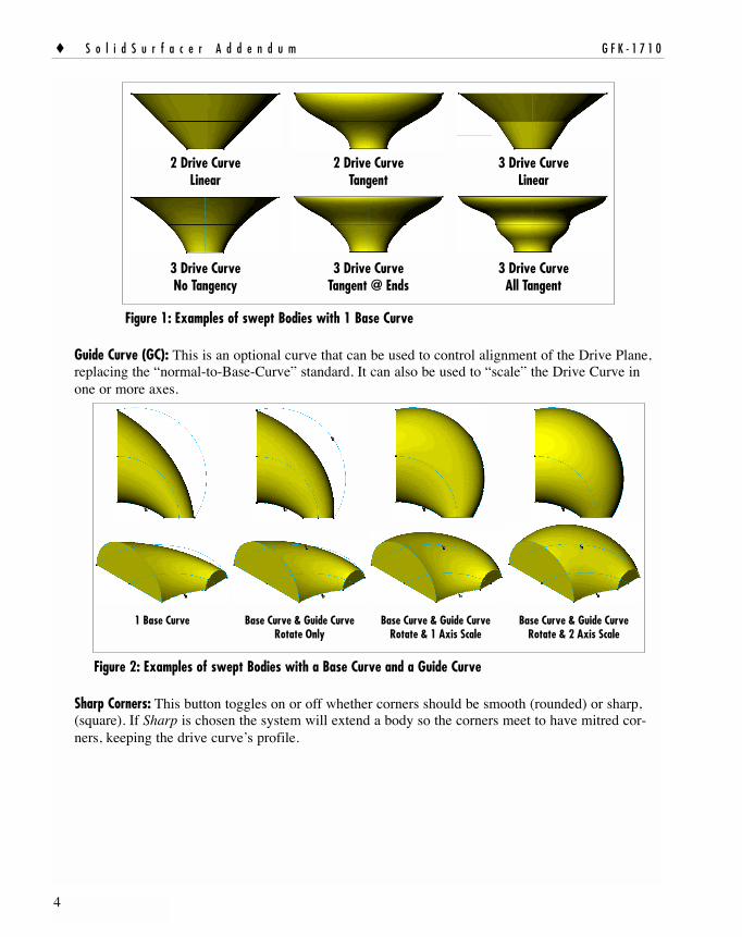
Figure 1: Examples of swept Bodies with 1 Base Curve
Guide Curve (GC): This is an optional curve that can be used to control alignment of the Drive Plane,replacing the “normal-to-Base-Curve” standard. It can also be used to “scale” the Drive Curve inone or more axes.
Figure 2: Examples of swept Bodies with a Base Curve and a Guide Curve
Sharp Corners: This button toggles on or off whether corners should be smooth (rounded) or sharp,(square). If Sharp is chosen the system will extend a body so the corners meet to have mitred cor-ners, keeping the drive curve’s profile.
1 Base Curve Base Curve & Guide CurveRotate Only
Base Curve & Guide CurveRotate & 1 Axis Scale
Base Curve & Guide CurveRotate & 2 Axis Scale
2 Drive CurveLinear
2 Drive CurveTangent
3 Drive CurveLinear
3 Drive CurveNo Tangency
3 Drive CurveTangent @ Ends
3 Drive CurveAll Tangent
4
� S o l i d S u r f a c e r A d d e n d u m G F K - 1 7 1 0
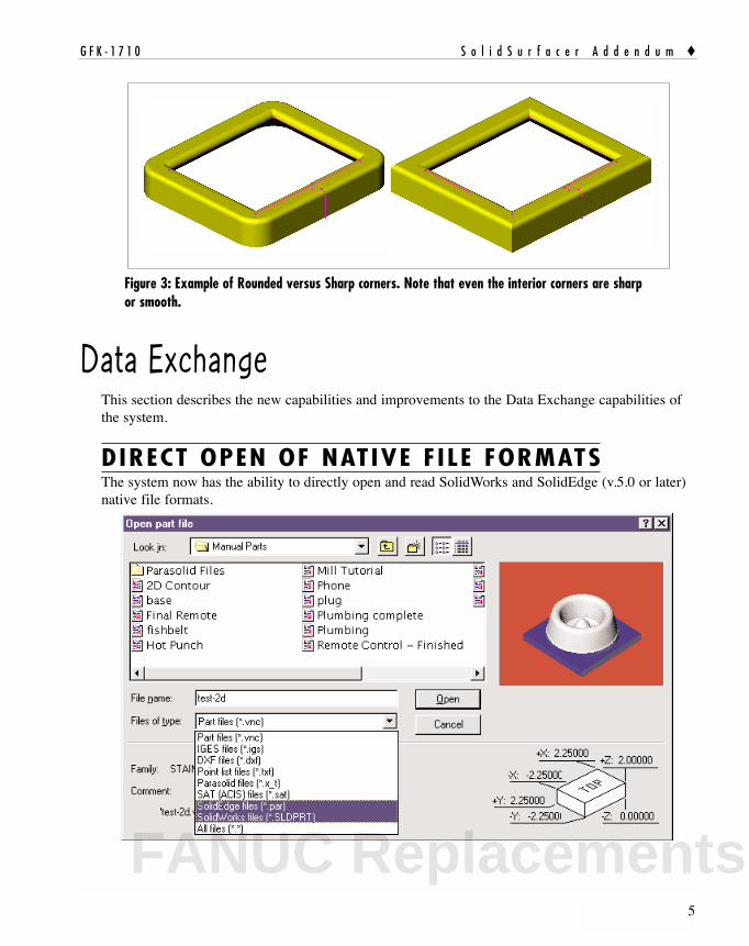
Figure 3: Example of Rounded versus Sharp corners. Note that even the interior corners are sharpor smooth.
Data ExchangeThis section describes the new capabilities and improvements to the Data Exchange capabilities ofthe system.
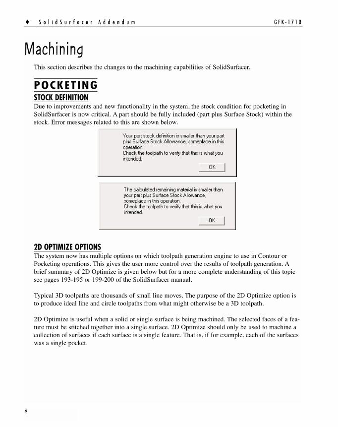
DIRECT OPEN OF NATIVE F ILE FORMATSThe system now has the ability to directly open and read SolidWorks and SolidEdge (v.5.0 or later)native file formats.
5
G F K - 1 7 1 0 S o l i d S u r f a c e r A d d e n d u m �
FANUC Replacements

IGES SURFACE EXPORTThe system can now export geometry and bodies as IGES surface entities. From the File menuselect Export. This will bring up the standard Open/Save dialog. Select IGES files from the Save asType pull down menu..
Once the file is named and Save has been clicked the following dialog will come up. The informa-tion may be altered as needed by the user.
When OK has been clicked the Export Filter dialog will come up. This allows the user to definewhat elements are to be exported and the measurement unit to be used. When the Process dialog hasbeen pressed the system will compile the IGES file and save it as directed.
IMPROVED SAT IMPORTSAT files may either be directly opened or they may be imported into a .vnc file. Importing a fileoffers the advantage of being able to bring in more than one file. The system will read the SAT fileto determine what it is and where it came from. This information is contained within the file’s head-er and will be displayed as seen in the following image. Older versions of these files do not havethis header information. Whatever information can be determined will be displayed in the dialog.
6
� S o l i d S u r f a c e r A d d e n d u m G F K - 1 7 1 0

7
G F K - 1 7 1 0 S o l i d S u r f a c e r A d d e n d u m �
Version: This is the SAT version that output the ACIS file. Earlier numbers mean older SAT files.Product: This is the CAD product used to create the SAT file.ACIS Version: This is the version of ACIS the file was saved as.Date: This is the date on which the file was created.Distance Resolution: This is the distance (not in measurable units) between which any two points arecoincident.Angle Resolution: The minimum determinable angle value based on distance resolution and measure-ment units.Entities: The total number of entities contained in the file. This can be just bodies or it can be bodiesas well as extraneous information. Valid Entities: The total number of valid entities the system can read, this may include invalid bodies.Bodies: The total number of bodies ACIS considers valid.Size Specifications for the Part Model: SAT files are written in generic units. It is not defined whetherthese units are millimeters, inches or meters.User Defined Units: The user is asked to define a conversion value for mm per unit. If the units areinches enter 25.4 mm/unit. Clicking on the in button will automatically enter this value in the con-version box. Be sure that the unit of measure for a part is the same as that designated in theDocument Control Dialog. If you do not know the original units of measure, make an estimatebased on the units shown in the dialog. This section will be grayed out if the units are specified inthe header.
FANUC Replacements
8
� S o l i d S u r f a c e r A d d e n d u m G F K - 1 7 1 0
MachiningThis section describes the changes to the machining capabilities of SolidSurfacer.
POCKETINGSTOCK DEFINITIONDue to improvements and new functionality in the system, the stock condition for pocketing inSolidSurfacer is now critical. A part should be fully included (part plus Surface Stock) within thestock. Error messages related to this are shown below.
2D OPTIMIZE OPTIONSThe system now has multiple options on which toolpath generation engine to use in Contour orPocketing operations. This gives the user more control over the results of toolpath generation. Abrief summary of 2D Optimize is given below but for a more complete understanding of this topicsee pages 193-195 or 199-200 of the SolidSurfacer manual.
Typical 3D toolpaths are thousands of small line moves. The purpose of the 2D Optimize option isto produce ideal line and circle toolpaths from what might otherwise be a 3D toolpath.
2D Optimize is useful when a solid or single surface is being machined. The selected faces of a fea-ture must be stitched together into a single surface. 2D Optimize should only be used to machine acollection of surfaces if each surface is a single feature. That is, if for example, each of the surfaceswas a single pocket.

Any combination of the Toolpath Optimization options may be chosen. The system will start withthe most simple and quick, try to generate toolpath, then move down the list to the next option ifoptimization fails. For example, in the previous image the system would run the 21/2D Optimize thenmove to the 2D Optimize a 3D Toolpath.
This option generates toolpaths very quickly. This option will generate2D toolpaths without surface tolerance if all selected faces are 2D. 2D
Only Optimize does not provide for undercut protection. See the Solid Surfacer manual for moreinformation about this option.
This option will work on all selected faces, 2D, 21/2D and 3D faces butonly 2 and 21/2D faces will produce optimized toolpath without surface
tolerance. For this option to work, all selected faces must be able to offset by the tool’s corner radiusamount. If the selected faces fail to be offset by the tool’s corner radius the optimization will notwork. The offsetting of faces fails when a face has an inside (concave) curvature smaller than theoffset amount or when there are faces smaller than the offset amount at an inside corner betweenfaces. If 21/2D Optimize succeeds in its offset calculation it will generate all toolpaths and will skipsubsequent optimizations. This option does not provide for undercut protection.
9
G F K - 1 7 1 0 S o l i d S u r f a c e r A d d e n d u m �
FANUC Replacements

The 2D/3D Combo Optimize checks to see if the selected faces have a2D range on top with a non-2D range toward the bottom. This option
will produce a combination of 2D and 3D toolpaths. First there will be a 2D range down to a depthwhere 3D toolpaths will be needed. 2D Only optimize will be used to within the tool’s corner radiusin Z of of the start of the 3D range. 3D toolpaths will be generated from this Z level down. Thismay produce some 3D toolpaths on 2D faces near the transition area in Z but this is safer than goug-ing the part. This option works best with single pockets as opposed to a large and complex group offaces that may transition from 2D to 3D at different Z depths in different areas. This option can sig-nificantly reduce toolpath generation time as the 2D Only Optimize is extremely fast.
This option only looks at 3D toolpaths. It does not generate any tool-paths, it only seeks to improve them. 2D Optimize a 3D Toolpath will
check to see if any 3D toolpaths were generated from 2D faces. If so it attempts to replace a sectionof the 3D toolpath with a 2D toolpath. This optimize does a good job of cleaning up slow 3D tool-path where 2D and 21/2D faces have failed.
MACHINING OPEN SIDED POCKETSThe system now has an enhanced ability to machine open sided pockets. This ability as it relates togeometry is fully detailed in the Production Addendum (page 11). With SolidSurfacer, geometrydoes not necessarily need to be created or defined as “air” for this function to work The part’s stockwill function as “air” geometry and bodies function as “wall” geometry.
The following example helps to illustrate machining open sided pockets. A model is created with abase, an island and a pocket inside the island.
To machine this model a pocketing process will be created along with drilled entry holes. This willall be done from one routine. The routine will consist of three operations: a hole operation, and twopocketing operations. Note that the toolpath extends to and rides on the stock diagram.
10
� S o l i d S u r f a c e r A d d e n d u m G F K - 1 7 1 0

When the operation is rendered we see that only one entry hole is drilled, that being for the pocketthat is bounded by the model. The model acts as a “wall” to the operation. Thus the tool will start atthe center and work its way outward. In this image we also see that the outer pocket, which has noboundary, only “air”, has been started from an edge and the tool is working inward.
Once the open-sided pocket is complete, the system moves on to the bounded pocket. Note that thisoperation is machining outward.
11
G F K - 1 7 1 0 S o l i d S u r f a c e r A d d e n d u m �
FANUC Replacements

SURFACING OPERATIONSFixture Clearance: A Fixture Clearance value may be defined inSurfacing operations. This is the distance from a fixture at which
the tool will retract and rapid over a fixture, then feed back down onto the part and continue cutting.A fixture may be defined as a body designated as a fixture, a face designated as a fixture and unse-lected faces on a body being machined.
CAM ENGINE TABSECOND GENERATION ENGINE
There is a new tab in the Process dialog referred to as CAM Engine. This tab provides access to a setof radio buttons labeled First Generation Engine and Second Generation Engine.
The First Generation Engine is the standard toolpath generator SolidSurfacer has always had. TheSecond Generation Engine is a newer toolpath generator that is still being fully explored and imple-mented. The Second Generation Engine is not functional for all Surfacing operations at this time butwill be in future releases. It is included because it is faster in certain situations or can provide ashorter toolpath. The toolpath generated by the Second Generation engine may not be visibly differ-
12
� S o l i d S u r f a c e r A d d e n d u m G F K - 1 7 1 0

ent from the First Generation engine at other times, it will look quite different. Primarily it isdesigned to produce a better, cleaner, more accurate toolpath. It is highly recommended that usersset the Second Generation Engine as the default choice for creating toolpaths.
When Second Generation Engine is chosen the system will attempt to use this toolpath generator,however, in some cases the system will seamlessly revert to the First Generation Engine. There is adialog next to the radio buttons that will inform the user as to the active toolpath engine based onthe type of Surfacing operation to be performed.
flow and Intersections operations are still handled by the First Generation engine. The SecondGeneration Engine is currently effective for creating 2-Curve Flow and Lace Cut operations. Not allLace Cut variations are enabled however. The Lace Cut variations that are enabled are:
Constant Z Rough, cut SurfacesZ Surfaces Offset Rough and both of its options, Constant Z Shift and Constant # of Passes.One Finish Pass on Surfaces and one of its three options, All Surfaces
Any Stepover Retract Options, Retract Clearance Plane choices and Toolpath Options will be validchoices for the Second Generation Engine. Should any of the other Lace Cut options be chosen thesystem will automatically switch to the First Generation Engine. Figure 4 illustrates the valid LaceCut options for the Second Generation Engine. Valid choices are shown in black while the itemshighlighted in gray illustrate what will be used by the First Generation Engine.
Figure 4: Illustration of Lace Cut options for Second Generation Engine.
13
G F K - 1 7 1 0 S o l i d S u r f a c e r A d d e n d u m �
FANUC Replacements

GEN2 LACE CUTFor the most part GibbsCAM has kept the visible differences between the first generation engineand the second generation engine at a minimum for an ease of transition. However, the behavior oflace cuts is different. One of the most apparent differences is that in Gen2 operations the toolpath isautomatically trimmed to the stock. Gen1 did not do this. Another large difference is that Gen1 didnot recognize vertical walls, Gen2 does. The biggest difference is that the Gen2 engine has incredi-ble gouge protection. You may notice a connect move in the toolpath that is neither a straight linenor a projected line but a combination of the two. This is the Gen2 engine maximizing gouge pro-tection but keeping the toolpath short.
Due to the gouge protection, a toolpath that is coincident with the stock boundary may retract to ahigher Z and continue cutting. Try adjusting the stepover to move the toolpath off of the part's edge.Adjusting the Past Stock allowance and the Surface Tolerance can also help.
Don't Extend Toolpath: The tool will only move to the edge ofthe part's selected faces. When it reaches unselected faces thetool will retract and rapid to where the toolpath continues.Extend Toolpath to Stock: The tool will move so that its tip orcenter is coincident with the edge of the stock. Extend Toolpath Clear of Stock: The tool will move a full diameterpast the stock boundaries.
The Gen2 engine will automatically cut past all edges on a part. This includesedges between two selected faces and mixed faces (selected and unselected
combinations). The results of Cut Over Edges with Don't Extend Toolpath are slightly more com-plex. Some variations on machining at vertical walls are detailed below.
SURFACE FLOW CUTStart Point: The control over the start point for SurfaceFlow operations has been improved by using the Climbcheckbox and the Top Down Passes / Bottom Up Passesradio buttons.
Cut Over Edges Off Cut past edge, feed down and continueCut to edge, retract and move to newfeed locationCut to edge, retract and move to newfeed location on edge
Cut Over Edges On Cut past edge, feed down and continueCut past edge, feed down and continue
Cut past edge, retract & move to feedinto edge
Both Faces SelectedMixed faces
Unselected Pocket
Note:If a part has a cavity and the lowest Z level of a cut is above the bottom of thecavity the tool will machine into the cavity to the bottom Z level. To avoid thisbe sure the bottom Z cut is below the cavity depth.
14
� S o l i d S u r f a c e r A d d e n d u m G F K - 1 7 1 0

The Climb or Conventional cut is controlled by a checkbox labeled Climb. When checked theprocess will be a “Climb” cut, if unchecked the system will default to a “Conventional” cut. TopDown and Bottom Up are radio buttons thus they are toggled to one or the other. By setting theseitems to how you would want to cut i.e. down or up and from the left or right side of the part, youwill get the results you are looking for. If Back and Forth is selected the climb or conventional set-ting will only be on the first pass. All additional passes will alternate.
2 CURVE FLOWWhen using the Second Generation Engine, the system can now produce 2 curve Flow operationsbased on multiple pairs of geometry. Previously, the system could only handle one pair at a time,now there is effectively no limit to how many pairs of geometry may be used as a constraint for thetoolpath. An example is shown in the following image. Note that the top of the taller boss is dese-lected causing the toolpath to rapid over that section of the part.
Notes:• On horizontal or near horizontal faces the system may not give the expected
result. Try changing the climb/conventional setting. • A Surface Flow process is not guaranteed to be specifically climb or conventional
on the first cut. These machining parameters are only used for designating thestart location of an operation.
15
G F K - 1 7 1 0 S o l i d S u r f a c e r A d d e n d u m �
FANUC Replacements

2.5D MATERIAL ONLYSome of this information is already included in the SolidSurfacer Addendum and the ProductionRelease Note. The emphasis of this Material Only data is on machining Solids and is a supplementto the data in the Production Release Note. Much of this information may be found in theProduction Release Note but is included here for ease of use.
DEFINITION2.5D Material Only calculates toolpath for all remaining material left on walls by prior operationsonly. Remaining material is stored for 2D operations; contouring, pocketing and drilling operations.Remaining material is NOT stored for 3D operations; Lace, Surface Flow and 2 Curve Flow cuts.Material Only supports custom stock definitions, sharp, bull nose, tapered, ball end mills and mostform tools. Undercutting tools are not supported. Material Only may be used as a single operation oras part of a multiple process group.
DESCRIPTIONWhen the Material Only option is selected the system will track the areas where material is left dur-ing an operation by creating closed shapes with both “WALL” and “AIR” features or a combinationshape for each occurrence of remaining material. During subsequent operations the system will gen-erate toolpath to remove only the material within these shapes if Material Only is selected. Toolpathgenerated in these areas is based upon an open sided pocket configuration
MACHINING PREFERENCESThe Allow Mill Material Only setting must be selectedin the Machining Prefs dialog box in order for the sys-tem to track and store remaining material conditions.Ifthe Material Only option is not going to be used inoperations it is strongly recommended that this optionbe deselected.
When this preference is on, the system will perform thecalculations needed for a Material Only operation evenif the calculations will not be applied. This informationwill also be saved with the part file. The additional pro-cessing power and disk space that can be gained byturning this option off when not used is significant.
PROCESS DIALOG SETTINGSOverhang and Material Only: Overhang is the distance a tool’sedge will move past an open boundary. The recommended valueis the tool radius. (For a more detailed explanation seeOverhang in the Production Addendum on page 45.)
16
� S o l i d S u r f a c e r A d d e n d u m G F K - 1 7 1 0

Past Stock and Material Only: Past Stock is the distance a tool’s edgeis allowed to travel into an open area to remove material. The rec-ommended value for Past Stock is the Tool Diameter minus 2.5times the maximum Surface Tolerance of any previous operation.
Example: The Past Stock value for a Material Only machining operation using a 0.5" diameter end-mill and a prior operation with a Surface Tolerance of .005" would be: 0.5" - (2.5*0.005) = 0.4875"
MATERIAL ONLY RELATED TO CLOSED POCKETS AND OPEN POCKETSWhen calculating toolpath for Material Only machining there are two different types of pockets, aclosed pocket and an open pocket. Each is briefly described below.
Closed Pockets and Material Only: A closed pocket is defined as a closed shape that is comprised of all“WALL” features. (See Geometry Context Menus in the version 5.1 Production Addendum on page25).
Open Pockets and Material Only: An open pocket is defined as a closed shape that is comprised ofeither all “AIR” features or a combination of “AIR” and “WALL” features. This type of shape isreferred to as a combination shape or combination geometry. (See Geometry Context Menus inProduction Addendum).
There are two methods for working with an open pocket when generating toolpath for Material Onlymachining, the Multiple Shapes and Combination Geometry methods.
When generating toolpath for Material Only machining using a solid body that has closed and/oropen pockets, SolidSurfacer uses the Multiple Shapes method. The Multiple Shapes method isdescribed below. (See Material Only on page 10 of the Production Release Notes for a descriptionof the Combination Geometry method).
Multiple Shapes Method: This is the recommended method for assuring the best toolpath when generat-ing toolpath for Material Only machining. This method requires at least two shapes. The first shapeis an all “AIR” shape, which represents the stock and another shape representing the pocket as anisland. This second shape is an all “WALL” shape. Using this method the system treats the pocket asan island inside the stock.
Notes: • A Past Stock value set too large will result in toolpath in areas where
no material is left from a previous operation, creating air cuts.• A Past Stock value set too small may result in toolpath that does not
clean up all the remaining material, leaving small amounts of material.
17
G F K - 1 7 1 0 S o l i d S u r f a c e r A d d e n d u m �
FANUC Replacements

To generate these shapes, SolidSurfacer does a horizontal slice of the solid body at each Z-level cutdepth defined in the process dialog box. The all “AIR” shape is based on the stock condition at eachZ-level step and the all “WALL” shape(s) are based on the part condition at each Z-level step.Example #1 below illustrates what the “AIR” and “WALL” shapes would look like at two differentZ-level steps.
• The first image, Image A, is the part body. The floor is at Z-zero, two walls are 1" high andthe other two walls are .375" high.
• Image B is the custom stock body. The outside is to size, leaving only the inside “pocket” tobe machined.
• Image C is an all “AIR” shape representing the stock body. Since the stock body is anextruded shape the stock shape is the same at each Z step cut depth.
• Image D consists of two all “WALL” shapes representing the 1" high walls of the pocket.These pocket shapes will be used when generating toolpath for all Z cut depths above .375".
• Image E contains four all “WALL” shapes representing both the 1" high and .375" highwalls. These pocket shapes will be used when generating toolpath for all Z cut depths below.375".
Example #1: Solids and Material Only - Multiple Shapes method
Image A - part body
1.0" high
1.0" high
0.375" high
0.375" highPocket Floorat 0.0"
Image B - custom stock body
Image C - "Air" shape Image D - Two "Wall" shapesThey represent the 1" walls
Image E - Four all "Wall" shapesThey represent the 1" and .375" walls
18
� S o l i d S u r f a c e r A d d e n d u m G F K - 1 7 1 0

OPTIMIZING MATERIAL ONLY WHEN MACHINING A SOLID BODY• Avoid full body selections. Only select the area (faces) to be cut.• Use 2.5D toolpath optimization. This will produce better toolpath (G2s and G3s not just G1s) and
will also allow for a tighter Surface Tolerance setting. Avoid undercuts when using the 2.5D tool-path optimization feature.
• Select Ignore Tool Profile when permissible. (Note - For more information on Ignore Tool Profilesee page 5 of the Production Release Notes.)
Trouble Shooting Material Only Results: • Tools with undercuts are not supported.• Material Only does not support custom stock bodies with undercuts.• The toolpath is not optimal or the tool retracts an undesirable amount due to lack of a Depth First
option:Depth First is not supported for Material Only cuts in this release.
• Toolpath is generated where no material is left from a previous operation:The Past Stock value for this operation is too large. Recommended value for Past Stock isthe Tool Diameter minus 2.5 times maximum Surface Tolerance of the previous operations.
• No toolpath is generated:The final cut depth may be below the stock bottom. Re-define the stock definition for thisoperation only. Move stock bottom to desired final cut’s Z-depth.
• If all else fails extract edge geometry and machine as geometry. When extracting the edgegeometry specify a small tolerance so the edges will be extracted as lines, arcs, and circles(analytics). Use the Multiple Shapes method described above.
19
G F K - 1 7 1 0 S o l i d S u r f a c e r A d d e n d u m �
FANUC Replacements

SolidSurfacer Tutorial Notes
Hot Punch: The Lace Cut depth should be -.8 instead of -.625 with a Desired Z Step of .25". Also,change the Top Level Z in the Text Contour operation to be -.3"
Lace Cut Text Contour
2D Contour: In the contour operation, be sure Depth First is selected and Entry/Exit Connect is off.Also select 2.5D Optimize in the Toolpath Optimizations list.
Note:Be sure to do all tutorials using the Gen1 engine. Some functionalitymay be different and the results of the machining may differ from theprinted tutorial if the Gen 2 Engine is used.
� S o l i d S u r f a c e r A d d e n d u m G F K - 1 7 1 0
20

G F K - 1 7 1 0 M a c h i n i n g E x e r c i s e s �
21
Machining ExercisesEXERCISE #1: PHONEThis exercise has been slightly modified from the version found onpage 221 of the SolidSurfacer manual. We have included this revisedversion in the addendum to illustrate the changes and provide anupdated tutorial
With the release of version 5 the system’s ability to machine opensided pockets has been improved and changed. The first pocketingoperation in the original exercise is performed differently now.
Originally we drilled an entry hole for the pocketing routine. In theexercise we found that the operation was incorrect, the tool wasmostly off the part, (see SolidSurfacer manual page 224) and modi-fied the final Z level to fix this error. We then continued on with thepocketing routine. Now this part qualifies as an open-sided pocket.The handset part of the model functions as an island in the middle of“air”. Thus, the system will pocket from the outside toward the cen-ter of the part.
In this exercise, we will use the standard pocketing process to roughthe part. Lace cut surfacing toolpaths will then be created to semi-finish the phone core. Finally, we will create finishing passes usingthe 2 Curve Flow and Surface Flow option; and complete themachining with an intersection toolpath.
• Open the Phone part created in Exercise #1 in the SolidModeling Exercises.
• Change the stock size to X+: 4.5, X-: -4.5, Y+: 2, Y-: -2, Z+: 0.1,Z-: -3. Enter a Clearance Plane value of .2"
• Create the following tool list.Tool #1: Rough end mill (rEM); diameter = 1/2"; corner
radius = 0.0625"; length = 3", flute = 2"; Tool #2: Ball end mill (bEM); diameter = 1/2"; length = 3";
flute = 2"Tool #3: Ball end mill; diameter = 1/4"; length = 3";
flute = 2"Tool #4: Ball end mill; diameter = 1/16"; length = 1.75";
flute = 1.5"FANUC Replacements
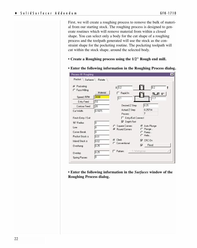
First, we will create a roughing process to remove the bulk of materi-al from our starting stock. The roughing process is designed to gen-erate routines which will remove material from within a closedshape. You can select only a body for the cut shape of a roughingprocess and the toolpath generated will use the stock as the con-straint shape for the pocketing routine. The pocketing toolpath willcut within the stock shape, around the selected body.
• Create a Roughing process using the 1/2" Rough end mill.
• Enter the following information in the Roughing Process dialog.
• Enter the following information in the Surfaces window of theRoughing Process dialog.
� S o l i d S u r f a c e r A d d e n d u m G F K - 1 7 1 0
22

G F K - 1 7 1 0 M a c h i n i n g E x e r c i s e s �
23
• Select the Phone body and click on Do It in the Machiningpalette.
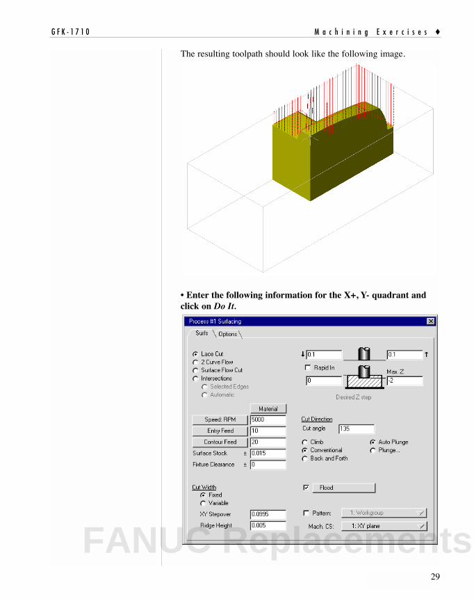
The toolpath generated should look like the following image.
FANUC Replacements

• Click on the Play button in the Cut Part Rendering palette.
Notice that the tool enters from the side of the part and cuts towardsthe center of the part.
• De-select the Pocketing operation in the Operations list andthrow away the Process tile from the Process list.
� S o l i d S u r f a c e r A d d e n d u m G F K - 1 7 1 0
24

G F K - 1 7 1 0 M a c h i n i n g E x e r c i s e s �
25
In order to create the semi-finishing lace cut toolpaths, we will slicethe body into four quadrants. This will allow us to machine the partin sections; each section using a different cut angle and cuttingtowards the top of the part.
• Create a new CS. Modify the CS to the YZ plane. Select thePhone body and slice it with the XZ and the YZ planes.
When sliced, you should have four pieces similar to the followingimage.
Our next step will be to perform a lace cut on each section of thephone, starting with the piece in the X-, Y- quadrant.
FANUC Replacements

• Create a Surfacing process using the 1/2" Ball end mill andenter the following information.
� S o l i d S u r f a c e r A d d e n d u m G F K - 1 7 1 0
26

G F K - 1 7 1 0 M a c h i n i n g E x e r c i s e s �
27
• Click on Do It to generate the following toolpath.
• Deselect the operation created for the X- Y- quarter. Select thesection in the X-, Y+ quadrant and enter the following informa-tion in the existing Surfacing process and click on Do It.
Note, the only information that has changed is the Cut Angle.
FANUC Replacements

The information contained in the Options window remains the sameon all of these lace cut operations.
The resulting toolpath should look like the following image.
• Enter the following information for the X+, Y+ quadrant andclick on Do It.
� S o l i d S u r f a c e r A d d e n d u m G F K - 1 7 1 0
28
G F K - 1 7 1 0 M a c h i n i n g E x e r c i s e s �
29
The resulting toolpath should look like the following image.
• Enter the following information for the X+, Y- quadrant andclick on Do It.
FANUC Replacements

Your cut part rendered image should look like the following image,with all tool cuts going toward the center of the part.
• While depressing the Ctrl key, select two of the sections andadd them back together using the Addition button in the SolidModeling palette.
Add the remaining two pieces, so that you again have a single solidbody for the phone core. Remember, boolean operations can only be
� S o l i d S u r f a c e r A d d e n d u m G F K - 1 7 1 0
30

G F K - 1 7 1 0 M a c h i n i n g E x e r c i s e s �
31
performed on two bodies at one time, so you will need to add thesetogether separately.
+ + +
The next operation to be performed will be a 2 Curve Flow aroundthe handset. For the tool to be able to perform the operation we willneed to offset the handset geometry.
• In CS1: XY Plane, double click on the darker geometry shownin the following image.
• Click on the Offset button in the Shapes palette.
• Enter the following information in the Shape Offset dialog andpress Do It.
FANUC Replacements

The Shape Offset function creates offset geometry to the inside andoutside of the original shape.
• Delete the offset geometry created on the inside of the originalshape.
With only geometry being viewed, your screen should look like thefollowing picture.
Oringal Shape
Outer Offset Shape
� S o l i d S u r f a c e r A d d e n d u m G F K - 1 7 1 0
32

G F K - 1 7 1 0 M a c h i n i n g E x e r c i s e s �
33
• Create a Surfacing process using the 1/4" Ball end mill andenter the following information.
FANUC Replacements

By looking at the top view we can see why we created the offset.The offset of .15" gives the tool room to perform the 2 Curve Flowoperation.
To create the 2 Curve Flow operation we will need to select align-ment points in the geometry similar to a Lofting modeling operation.Then, we will need to select the body.
• Select alignment points in the order shown in the followingimage.
• While holding down the Ctrl key, select the body and click onDo It in the Machining palette.
� S o l i d S u r f a c e r A d d e n d u m G F K - 1 7 1 0
34

G F K - 1 7 1 0 M a c h i n i n g E x e r c i s e s �
35
The following toolpath will be generated.
When the operation is cut part rendered, the body should be similarto the following image.
FANUC Replacements

• Create a Surfacing process using tool #3 and enter the followinginformation.
� S o l i d S u r f a c e r A d d e n d u m G F K - 1 7 1 0
36

G F K - 1 7 1 0 M a c h i n i n g E x e r c i s e s �
37
• Depress the Face Selection button and select the top face of thehandset as shown in the following image.
• Click on Do It in the Machining palette and the following tool-path should be generated.
FANUC Replacements
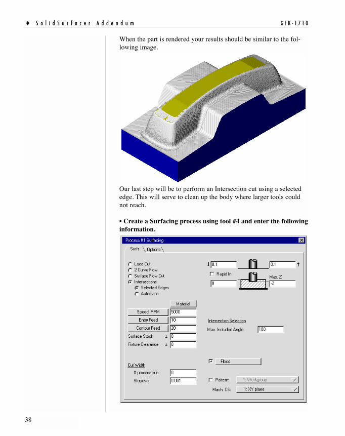
When the part is rendered your results should be similar to the fol-lowing image.
Our last step will be to perform an Intersection cut using a selectededge. This will serve to clean up the body where larger tools couldnot reach.
• Create a Surfacing process using tool #4 and enter the followinginformation.
� S o l i d S u r f a c e r A d d e n d u m G F K - 1 7 1 0
38

G F K - 1 7 1 0 M a c h i n i n g E x e r c i s e s �
39
• Enter the following information in the Options window.
• Turn on Edge Selection and double click anywhere on the edgeshown in the following image.
FANUC Replacements

• Click on Do It in the Machining palette.
The resulting toolpath should look like the following image.
When cut part rendered the part should look like this.
� S o l i d S u r f a c e r A d d e n d u m G F K - 1 7 1 0
40