Embed Size (px)
Citation preview

Failure of Notched Laminates Under Out-of-Plane Bending. Phase VI 2013 Technical Review John Parmigiani Oregon State University

2
Failure of Notched Laminates Under Out-of-Plane Bending, all phases
• Motivation and Key Issues Develop analysis techniques useful in design of composite aircraft structures under out-of-plane loading (bending and shear)
• Objective Determine failure modes and evaluate capabilities of current models to predict and model failure
• Approach • Modeling of progressive damage development and
delamination using ABAQUS • Experimentation to validate models and to identify key
failure mechanisms

3
• Principal Investigators & Researchers • John Parmigiani (PI) • Imran Hyder & Nasko Atanasov
grad students (2012-13) • FAA Technical Monitor
• Curt Davies • Lynn Pham
• Other FAA Personnel Involved • Larry Ilcewicz
• Industry Participation • Gerry Mabson, Boeing (technical advisor) • Tom Walker, NSE Composites (technical advisor)
Failure of Notched Laminates Under Out-of-Plane Bending, all phases

• Phase I (2007-08) • Out-of-plane bending experiments w/composite plates • ABAQUS modeling with progressive damage
• Phase II (2008-09) • ABAQUS modeling with buckling delamination added • Sensitivity study of (generic) material property values
• Phase III (2009-10) • ABAQUS modeling w/ more delamination interfaces
4
Project History

5
Project History
• Phase IV (2010-11) • Further study of modeling of out-of-plane bending • Sensitivity study of (Boeing) material property values
• Phase V (2011-12) • Out-of-plane shear (mode III) experiments • Evaluate the ABAQUS plug-in Helius MCT

6
2012-13 Project
• Phase VI • Task 1: Investigate non-traditional layups (NTL) for
optimization of out-of-plane bending performance • Task 2: Determine effective finite element analysis
techniques for out-of-plane shear (mode III)
• Today’s Topics • Update on optimization • Review and update of out-of-plane shear

7
Update on optimization • Optimization
• Maximize failure load • Allow plies in15° increments
• To begin, a genetic algorithm approach was used • Due to long FEA run times, a simplified 8-ply model
without a notch was used. Result was all-zeros (correct) • Next a simplified 10-ply model w/ notch was pursued
(actual panels are 20 and 40 plies) • Even with simplified model, 10 days of runs required to
identify a solution of 0/0/-45/-45/-45/90/0/0/0/0 • This solution is not quite the optimum as all-zeroes gives a
failure load 1.5% higher.
Half model of out-of-plane bending

8
Update on optimization
• Given long run time and failure to find true optimum, genetic algorithms were not pursued further
• Next idea pursued was to use a Design-of-Experiments approach to identify significant factors • Explore perturbations in ply angle about zero-degrees
i.e. -15/0/15 • Use a fractional factorial design • For no-notch case, all-zeros is obvious optimum and the
method correctly gives this result • For notched-case, it is not obvious that all-zeros will be
optimum

9
Update on optimization
• Using DoE approach for notched panel, all-zeros was found to be optimal (i.e. gave maximum failure load)
• Fracture path was found to be self-similar. • Self-similar result was somewhat surprising
so comparisons were made to all-zeros in tension and compression
• All zeros tension case gave the expected splitting failure mode
Tension Compression
Bending

10
Update on optimization
• Current Status • For the notched-panel geometry of this study, an all-zero-
degree plies lay-up gives the maximum failure load for pure out-of-plane bending
• Exploration of “more interesting” cases of multiple loads and general far-field boundary conditions requires more sophisticated computational equipment and validation of current mode III work and is deferred to a later project.

Review and update of out-of-plane shear
11
• Experimental Set-up & Plan • Edge-notched CF panels displaced to maximum load • Mode III fracture • Metrics
• Applied displacement • Applied load • Notch-tip strain field (via DIC, digital image correlation)
• Six ply layups • Six specimens / layup
• Three “up” • Three “down”

12
0 20 40 60 80 100 120 140 160 180 200 2200
1
2
3
4
5
6
7
Deflection (mm)
Loa
d (K
N)
40 Ply - 30% Zero Panel Load Deflection
Test 1 - Up Test 2 - Down Test 3 - Up Test 4 - down Test 5 - Up Test 6 - Down Test Average
Review and update of out-of-plane shear
Layup (#plies / %
zero degree)
MEAN Max Force [kN]
40/50% 5.473 40/30% 5.708 40/10% 4.101 20/50% 1.795 20/30% 1.531 20/10% 1.259
UP UP DOWN DOWN
Maximum load
Linear region

• FEA modeling • Use progressive damage to reduce material stiffness and strength as fracture occurs. • Stiffness and strength reductions cause strain softening and mesh dependence (results depend on mesh density and do not converge to a unique solution) • Mesh selection method used is to choose the coarsest mesh giving a converged elastic solution
• Successfully used out-of-plane bending study • Does not depend on experimental data (is not a curve fit)
Review and update of out-of-plane shear

4 Element Tip 8 Element Tip 12 Element Tip
20 Element Tip 24 Element Tip
• Seven notch-tip meshes were analyzed • 20 element tip was selected based on elastic
convergence (not experimental data)
16 Element Tip
32 Element Tip
Review and update of out-of-plane shear

15
• Using this mesh, six approaches are being pursued • Abaqus w/ Hashin progressive damage model
• 1 element layer, no ply-to-ply delamination (no VCCT*) • 5 element layers, no ply-to-ply delamination (no VCCT*) • 5 element layers, ply-to-ply delamination (VCCT*)
• Abaqus w/ Helius:MCT plug-in • 1 element layer, no ply-to-ply delamination (no CZ**) • 5 element layers, no ply-to-ply delamination (no CZ**) • 5 element layers, ply-to-ply delamination (CZ**)
* VCCT: Virtual Crack Closure Technique ** CZ: Cohesive Zone
Review and update of out-of-plane shear

16
• Results for Abaqus w/ Hashin & w/o delamination capability have been completed and, in general, model predictions are too high.
Review and update of out-of-plane shear
17
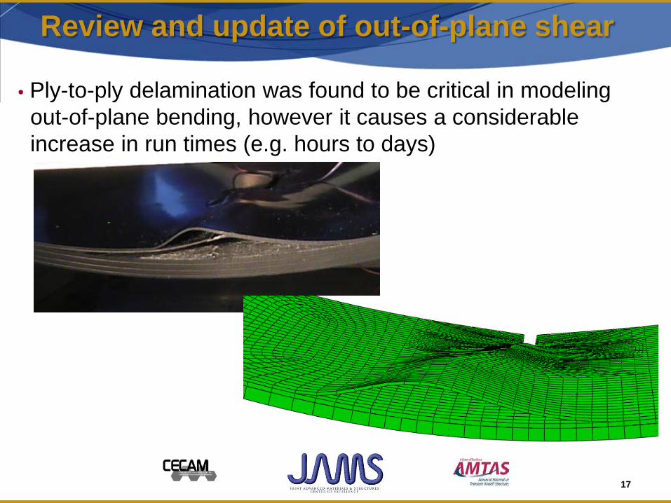
• Ply-to-ply delamination was found to be critical in modeling out-of-plane bending, however it causes a considerable increase in run times (e.g. hours to days)
Review and update of out-of-plane shear

18
• Current efforts are focused on adding ply-to-ply delamination to models
• Location of interfaces appears to be important • Out-of-plane bending models appear to be more tolerant of “misplaced” interfaces
Review and update of out-of-plane shear
Delamination
Experiment
Model w/ interface @ top 90-degree ply
Model w/ interface @ second 90-degree ply

19
Looking Forward
• Benefit to Aviation – Provide experimentally-validated FEA analysis
methods for composite materials – Explore new analysis techniques – Identify, via experiment and analysis, failure modes of
composites under relevant loading conditions – Educate graduate students in relevant topics
• Future needs – Continue to refine and define appropriate design and
analysis tools for aircraft design and analysis of composite materials
– Experimentally validate conclusions

End of Presentation.
Thank you.
20