Embed Size (px)
Citation preview

Failure of Notched Laminates under Out-of-Plane Bending.
Phase IV Fall 2011 Meeting
John P. Parmigiani & Thomas Wright Oregon State University

Failure of Notched Laminates Under Out-of-Plane Bending. Phase IV
• Motivation and Key Issues Develop analysis techniques useful in design of composite aircraft structures under out-of-plane loading (bending and shear)
• Objective Determine failure modes and evaluate capabilities of current models to predict failure
• Approach • Experiments: Mode 3 fracture • Modeling: Progressive damage development and
delamination (ABAQUS)

Failure of Notched Laminates Under Out-of-Plane Bending. Phase IV
• Principal Investigators & Researchers – John Parmigiani (PI) & Brian Bay, OSU faculty – Will Beattie & Thomas Wright, OSU grad students
• FAA Technical Monitor – Curt Davies – Lynn Pham
• Other FAA Personnel Involved – Larry Ilcewicz
• Industry Participation – Gerry Mabson, Boeing (technical advisor) – Tom Walker, NSE Composites (technical advisor)

Project Overview
Phase I (2007-08) • Out-of-plane bending experiments w/composite plates • ABAQUS modeling with progressive damage
Phase II (2008-09) • ABAQUS modeling with buckling delamination added • Sensitivity study of (generic) material property values
Phase III (2009-10) • ABAQUS modeling w/ more delamination interfaces

Project Overview
• Phase IV (2010-11) – Out-of-plane shear experiments
& ABAQUS modeling – Further study of additional delamination interfaces for
out-of-plane bending – Initiating vs. propagating toughness values for
out-of-plane bending – Feasibility of Abaqus/Explicit and XFEM for future work – Sensitivity study using Boeing mat’l property values – Special cases: all-ninety and all-zero degree plies for
out-of-plane bending

Today’s Topics
• Sensitivity study w/ Boeing material property values
• Effects of additional delamination interfaces • Feasibility of XFEM for future work • Feasibility and accuracy of Abaqus/Explicit for
future work
Out-of-plane Shear work was covered during 2011 JAMS meeting, and will be continued in Phase V. Initiating vs. propagating toughness values were covered during 2011 JAMS meeting. All-ninety and all-zero degree plies will be continued in Phase V.

Today’s Topics
• Sensitivity study w/ Boeing material property values
• Effects of additional delamination interfaces • Feasibility of XFEM for future work • Feasibility and accuracy of Abaqus/Explicit for
future work

Sensitivity Study
• Using design-of-experiments techniques, analytically* investigate the effect of variations in strength parameters on the failure load of two notched-panel layups • #1: 40% zero-degree plies • #2: 20% zero-degree plies • Loading: Out-of-plane bending • Panel dimensions
• 18-in long • 5-in wide • 20 plies • 0.25-in wide, 1-in long
center notch
* Study consists exclusively of Abaqus simulations
Abaqus half-model
Sensitivity Study
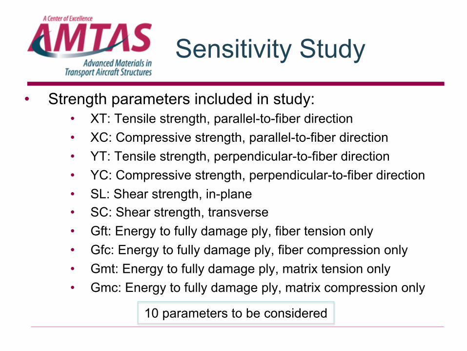
• Strength parameters included in study: • XT: Tensile strength, parallel-to-fiber direction • XC: Compressive strength, parallel-to-fiber direction • YT: Tensile strength, perpendicular-to-fiber direction • YC: Compressive strength, perpendicular-to-fiber direction • SL: Shear strength, in-plane • SC: Shear strength, transverse • Gft: Energy to fully damage ply, fiber tension only • Gfc: Energy to fully damage ply, fiber compression only • Gmt: Energy to fully damage ply, matrix tension only • Gmc: Energy to fully damage ply, matrix compression only
10 parameters to be considered

Sensitivity Study
• Design-of-Experiments Plan • Vary each parameter +/- 20% from nominal value • Use a 2-level fractional factorial
• Prior Work: Study conducted in earlier project phase • Generic material properties • 2^10-6 fractional-factorial design (16 runs) • Results showed key parameters for both layups to be
• Gft: Energy to fully damage ply, fiber tension • XT: Tensile strength, parallel-to-fiber • Gfc: Energy to fully damage ply, fiber compression • XC: Compressive strength, parallel-to-fiber
• Limited number of runs precluded information on interactions!
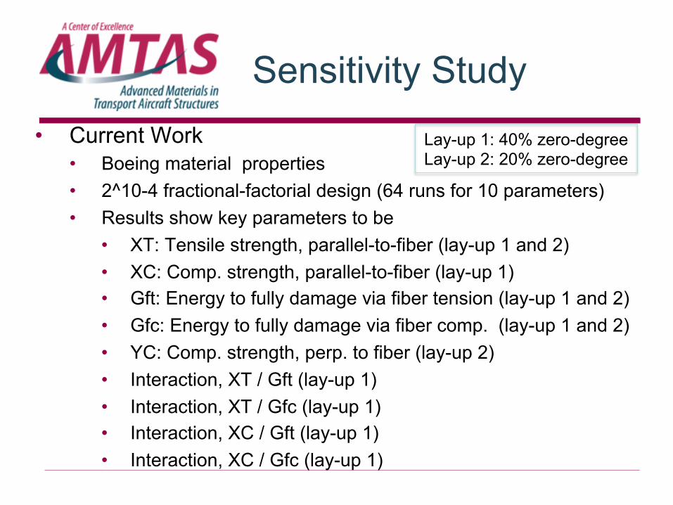
Sensitivity Study • Current Work
• Boeing material properties • 2^10-4 fractional-factorial design (64 runs for 10 parameters) • Results show key parameters to be
• XT: Tensile strength, parallel-to-fiber (lay-up 1 and 2) • XC: Comp. strength, parallel-to-fiber (lay-up 1) • Gft: Energy to fully damage via fiber tension (lay-up 1 and 2) • Gfc: Energy to fully damage via fiber comp. (lay-up 1 and 2) • YC: Comp. strength, perp. to fiber (lay-up 2) • Interaction, XT / Gft (lay-up 1) • Interaction, XT / Gfc (lay-up 1) • Interaction, XC / Gft (lay-up 1) • Interaction, XC / Gfc (lay-up 1)
Lay-up 1: 40% zero-degree Lay-up 2: 20% zero-degree

Sensitivity Study • Current Work, Summary & Conclusions:
Factors influencing failure moment • Both higher and lower percent-zero-degree-ply lay-ups showed
fiber fracture-energy and fiber tensile-strength to be key… … fibers are primary load-carrying components
• The lower percent-zero-degree-ply (more compliant) lay-up also showed matrix compressive strength to be key… … less stiff, so matrix properties more relevant
• The higher percent-zero-degree-ply lay-up (more stiff) also showed fiber compressive-strength and fiber strength & fracture energy interactions to be key… … strength & energy interaction likely indicating displacement-to-fracture is important as lay-up becomes stiffer

Today’s Topics
• Sensitivity study w/ Boeing material property values
• Effects of additional delamination interfaces • Feasibility of XFEM for future work • Feasibility and accuracy of Abaqus/Explicit for
future work
Additional Interfaces
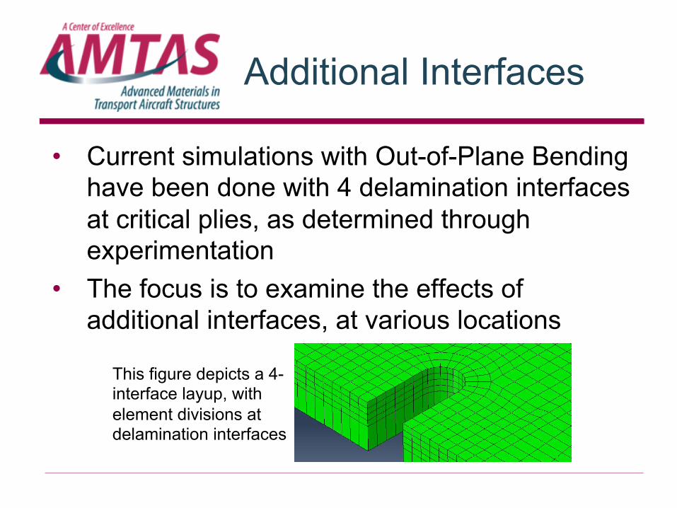
• Current simulations with Out-of-Plane Bending have been done with 4 delamination interfaces at critical plies, as determined through experimentation
• The focus is to examine the effects of additional interfaces, at various locations
This figure depicts a 4-interface layup, with element divisions at delamination interfaces

Additional Interfaces
• One 40 ply lay-up w/ interfaces at different locations • “Simulation Plan”: interfaces near zero-degree plies
• Evaluate using: • Maximum applied moment • Run Time • Convergence
Number of Interfaces
Configurations # of Configurations (#plies-interface-#plies-interface, etc.)
2 2 (32-7-1, 32-3-5) 4 1 (32-3-2-2-1) 5 4 (30-2-3-2-2-1, 24-3-4-3-3-3, 27-4-3-3-2-1, 31-1-2-1-2-3) 6 5 (25-5-2-3-2-2-1, 31-1-1-2-1-2-2, 22-2-3-4-3-3-3,
24-3-4-3-3-2-1, 27-3-2-3-2-2-1)

Additional Interfaces
• Due to convergence issues, some configurations of delamination interfaces did not produce a maximum moment
• Computing time was greatly increased
Number of Interfaces 2 2 4 5 5 5 Max Moment [in-lb] N/A 1030.3 1019.4 998.4 1042.4 N/A Run Time [hr] 43.3 7.7 136.4 116.3 59.9 184.5
Number of Interfaces 5 6 6 6 6 6 Max Moment [in-lb] N/A 1075.5 N/A 1007.1 1062.0 N/A Run Time [hr] 184.5 238.0 191.3 375.8 491.1 342.4
Additional Interfaces
Conclusions: • Additional interfaces do not greatly affect ( < 6% )
recorded maximum moments • However, as interfaces are increased, convergence
becomes more difficult • Additional interfaces significantly increase run times • When deciding where to put interfaces, extra
interfaces will not hurt accuracy, but will increase run time, if convergence can even be reached

Today’s Topics
• Sensitivity study w/ Boeing material property values
• Effects of additional delamination interfaces • Feasibility of XFEM for future work • Feasibility and accuracy of Abaqus/Explicit for
future work

eXtended Finite Element Method
• Purpose of this portion of the project is to conduct a preliminary investigation of the feasibility of XFEM
• Conventional FEM only permits crack propagation along element boundaries
• XFEM allows for cracks to propagate through the interior of elements
• Designed for use of fiber and matrix cracking in laminated composites

eXtended Finite Element Method
Difficulties in modeling and implementing: • XFEM does not support use of Hashin Damage
criterion (used Max Stress) • Cannot use shell or solid composite elements (used
individual layers) • Model must have one ply per element due to non-
support of shells and solid composites • With current mesh, and necessity for minimum of 20
layers, temporary storage space must be very large

eXtended Finite Element Method
• Convergence issues occurred before max applied moment was found
• Approximations of damage criteria do not allow for accurate results
• XFEM in Abaqus in its current form is not useful for the purpose of this project

Today’s Topics
• Sensitivity study w/ Boeing material property values
• Effects of additional delamination interfaces • Feasibility of XFEM for future work • Feasibility and accuracy of Abaqus/Explicit for
future work
Abaqus/Explicit
• Explicit methods are used for analyses like: • High-Speed dynamics • Large, nonlinear, quasi-static analyses • Highly discontinuous postbuckling • Extreme deformations
• Utilizes a constant, very small time increment • No iteration or convergence checking required
• Previous work in Abaqus/Standard has produced major issues with convergence
• Since Abaqus/Explicit is stable, it is of interest

Abaqus/Explicit
• Stable time increment is determined by Abaqus, and cannot be changed by the user
• Total time can be defined by user which changes run time of simulation
• Longer total time decreases dynamic effects but increases run time • ∆t is referred to as stable time increment:
∆!= #↑% /√)⁄+ • Le is the characteristic element length • E is the Young’s modulus • ρ is the current material density

Abaqus/Explicit
• Goal: Compare implicit and explicit approaches to modeling the fracture of specimens of this study
• Study consisted of making several runs at a range of total times and comparing: • Failure moment (Experimental vs. Standard
vs. Explicit) • Run time (Standard vs. Explicit) • Energy (Verify Quasi-static)

Abaqus/Explicit
• For Abaqus/Explicit analysis to be considered quasi-static, the kinetic energy (ke) must be less than 10% of the internal energy (ie)
• Several runs of varying total times were completed with one of the lay-ups

Abaqus/Explicit
Total Time [s] Max Moment [in-lb] Run time [hr] 2.0 904.6 124.7 1.5 962.5 165.7 1.0 906.1 104.3 0.5 1050.8 45.7 0.25 931.6 18.1 0.10 1390.5 9.3 0.05 1219.7 3.7
Experimental Max Moment = 906 in-lb
Maximum applied moments and run times of several explicit runs. Large variation in moment was likely due to dynamic issues at smaller total times

Abaqus/Standard
Plot comparing Internal and Kinetic Energy during an Standard Run
Time
0
Ene
rgy
• Kinetic energy is zero because it is a static, implicit analysis
• Internal energy gradually slopes upward throughout the run
• All Abaqus/Standard runs completed for this project have the same general form

Abaqus/Explicit
Plot comparing Internal and Kinetic Energy during an Explicit Run
Time
Ene
rgy
0
• Kinetic energy stays fairly low, with the exception of a spike
• Internal energy has large drop at location of the spike in kinetic energy
• This does not correspond to normal implicit analysis

Abaqus/Explicit
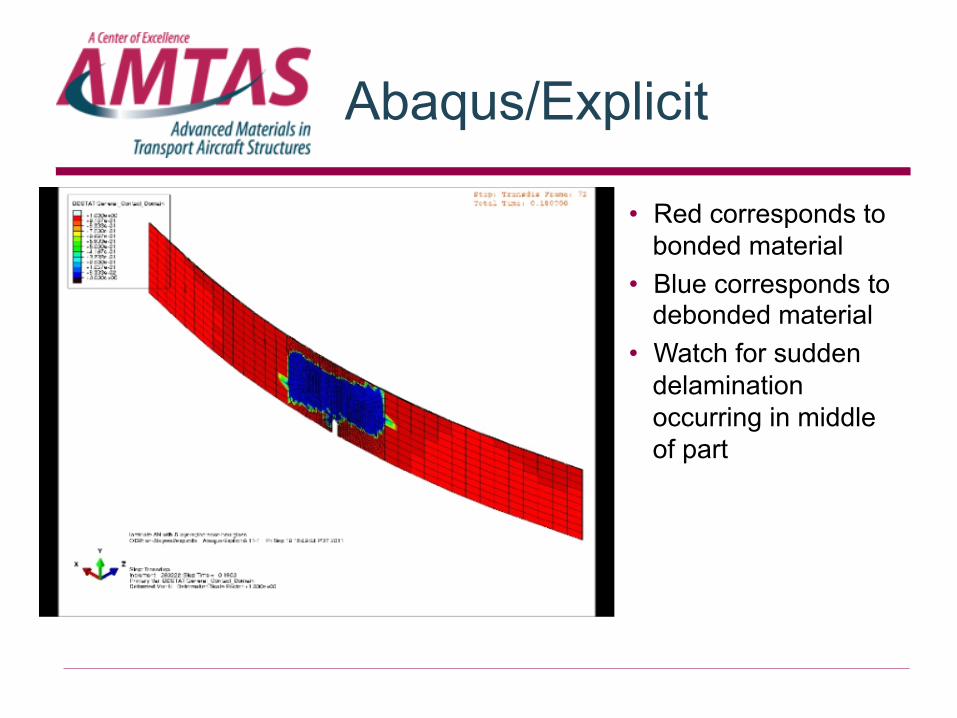
• Red corresponds to bonded material
• Blue corresponds to debonded material
• Watch for sudden delamination occurring in middle of part
Abaqus/Explicit
• Red corresponds to bonded material
• Blue corresponds to debonded material
• Watch for sudden delamination occurring in middle of part

Abaqus/Explicit
• Sudden massive delamination is the cause of the big drop in internal energy and spike in kinetic energy
• This is a dynamic event which is inconsistent with Standard analysis and with the experiments performed
• Considerably longer total time would be necessary to remove dynamic event

Abaqus/Explicit
• Completed one run of each layup using Abaqus/Explicit with total time of 2 seconds
• The run times range from approximately 5 days to over 22 days
• A significant increase in total time is impractical
Layup: # of plies (% 0°)
Run Time [hrs]
20 (10%) 149.7
20 (30%) 334.5
20 (50%) 241.4
40 (10%) 541.9
40 (30%) 222.3
40 (50%) 124.7

Abaqus/Explicit
Conclusions: • 2.0 seconds is not a long enough total time to provide
accurate results using Abaqus/Explicit • Increasing total time is not feasible, given current run
times of over three weeks • While there were no convergence issues, the amount
of time necessary to achieve an accurate solution using Abaqus/Explicit proves it is not a feasible solution for future work
• Failure to model a quasi-static simulation means Abaqus/Explicit is not a useful tool for this project

Questions

Abaqus/Explicit
• Why not try mass scaling? ∆!= #↑% /√)⁄+
• Multiplying density by x2 causes ∆t to increase by x • To bring run time for Explicit at 2 second total time
down to a comparable level with Standard, density must be increased by an order of magnitude
• Even that order of magnitude increase only makes a 2 second total time comparable, but a much longer total time is necessary, so two orders of magnitude increase of ρ is likely necessary


![Bending Test - FSv CVUT: katedra mechaniky [k132]mech.fsv.cvut.cz/~nezerka/files/Bending Test - tutorial.pdfthe notched beam stiffness can be found in the Appendix,A. Knowing the Young’s](https://img.dokumen.tips/doc/110x75/5aa62e777f8b9ae7438e7df0/bending-test-fsv-cvut-katedra-mechaniky-k132mechfsvcvutcznezerkafilesbending.jpg)