Embed Size (px)
Citation preview

FAG Motion GuardCHAMPION.CONTROL-IMPULSE
Automatic lubricator
User manual
2 BA 24 Schaeffler Group Industrial
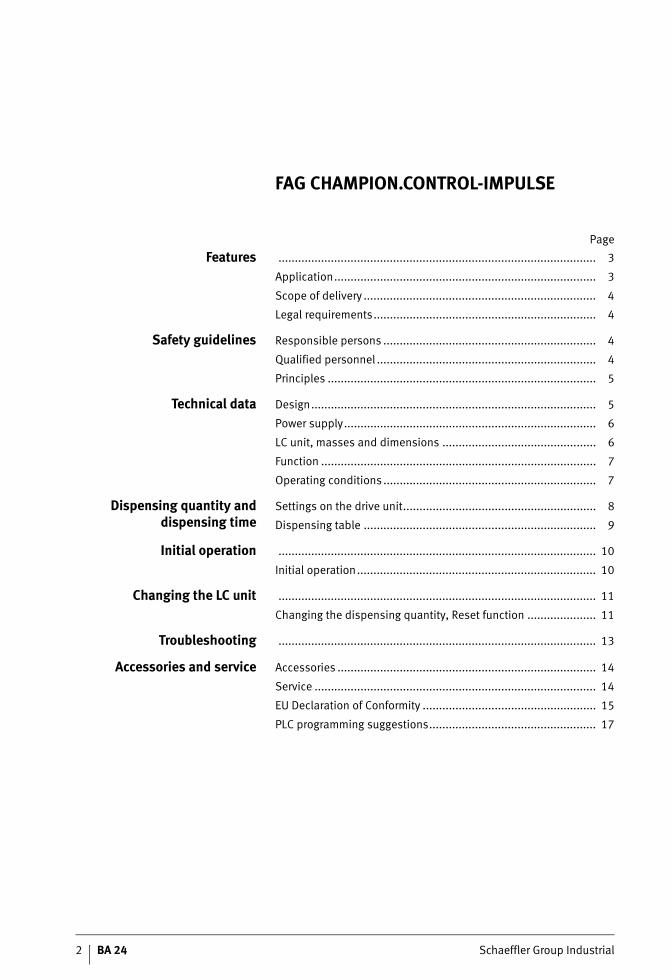
Page
Features ................................................................................................. 3
Application................................................................................ 3
Scope of delivery ....................................................................... 4
Legal requirements.................................................................... 4
Safety guidelines Responsible persons ................................................................. 4
Qualified personnel ................................................................... 4
Principles .................................................................................. 5
Technical data Design....................................................................................... 5
Power supply............................................................................. 6
LC unit, masses and dimensions ............................................... 6
Function .................................................................................... 7
Operating conditions ................................................................. 7
Dispensing quantity anddispensing time
Settings on the drive unit........................................................... 8
Dispensing table ....................................................................... 9
Initial operation ................................................................................................. 10
Initial operation......................................................................... 10
Changing the LC unit ................................................................................................. 11
Changing the dispensing quantity, Reset function ..................... 11
Troubleshooting ................................................................................................. 13
Accessories and service Accessories ............................................................................... 14
Service ...................................................................................... 14
EU Declaration of Conformity ..................................................... 15
PLC programming suggestions................................................... 17
FAG CHAMPION.CONTROL-IMPULSE
Schaeffler Group Industrial BA 24 3
Features This user manual describes how to work safely on and withthe automatic lubricator FAG Motion Guard CHAMPION.CONTROL-IMPULSE. The safety guidelines must be observed.
Attention! Any persons working on and with the lubricator must have the user manual available for their work and must observe the relevant information and guidelines.
The user manual must always be complete and in a fully legible condition.
The relevant disposal guidelines must be observed.
From this point onward, the FAG Motion Guard CHAMPION.CONTROL-IMPULSE is referred to as the lubricator and the lubricant cartridge as the LC unit.
Application The lubricator is clearly identified by a sticker on the drive unit and the LC unit.
The lubricator is intended for machinery and plant where lubrication is to be carried out during running and feedback to the machine is required.
The lubricator supplies the lubrication point with oil or grease ata pressure up to max. 5 bar constantly, precisely and irrespectiveof temperature and can also be switched on and off under machine control.
Characteristic areas of application include the lubrication points on rolling and plain bearings, drive and conveyor chains,guidance systems, open gearboxes and seals.
Attention! The lubricator must only be used for the purposes stated in theorder and confirmed by Schaeffler KG and in accordance withthe conditions of use, settings and variations described in this user manual.
It must be ensured that the correct power supply and connectionto the plant or controller (for example a PLC) are provided.
Connection should only be carried out using the original connection cable.
Connection should only be made by qualified skilled personnel and installation must comply with national standards such as IEC or VDE.
The lubrication system must only be equipped with connections and pressure-resistant feed lines from Schaeffler KG.
The lubricator must be protected against chemically aggressive ambient media.
FAG CHAMPION.CONTROL-IMPULSE

4 BA 24 Schaeffler Group Industrial
FAG CHAMPION.CONTROL-IMPULSE
Scope of delivery The lubricator can be used with three LC units of different sizesto meet individual requirements. The volume of the LC unit andthe lubricator correspond to the specific order.The delivery should be checked as soon as it is received. Schaeffler KG accepts no liability for any defects that are thesubject of subsequent complaints.
Any damage in transport must be reported as a complaint tothe deliverer, any missing items or defects must be reported asa complaint to Schaeffler KG.
Legal requirementsLiability The information, data and guidelines given in the user manual
were current at the time of editorial approval. The data, illustrations and descriptions cannot be used as grounds for any claims relating to lubricators that have already been delivered.
Attention! Schaeffler KG accepts no liability for any damage or operational malfunctions that occur as a result of improper use or unauthorised changes to the drive unit or LC unit.
This also applies to incorrect work on or with the lubricator,errors in use or adjustment or incorrect variation sizes ofthe lubricator or a failure to observe the user manual.
Safety guidelinesResponsible persons
Operator The operator is the natural or juristic person that uses the lubricator or on whose instruction the lubricator is used.
Attention! The operator or his safety co-ordinator are responsible for compliance with all relevant specifications, guidelines and regulations.
All work on and with the lubricator may only be carried out by qualified personnel.
In mounting and maintenance of the lubricator, the relevant accident preventions specifications and safety specifications must be observed.
Qualified personnel Persons that are authorised by the person responsible for safetyof the plant, on the basis of their experience and knowledge,to carry out the activities required in the specific case.

Schaeffler Group Industrial BA 24 5
Principles The lubricator must be filled with the correct oil or grease and adjusted such that, when it is correctly adjusted and mountedand used as specified, it functions without defects and does not cause any hazards. This also applies to the interaction withthe complete plant and the points to be lubricated.
Material damage that could arise due to failure of the lubricator must be prevented by suitable measures.
All retrofitting, modification and conversion of the lubricator is prohibited.
Attention! While working on machinery and plant, the safety guidelines and user manuals of the manufacturers must be observed.
The LC unit must not be opened or refilled under any circumstances.
The safety data sheets for the oils and greases must be observed.
Only original LC units from Schaeffler KG may be used.
Technical dataDesign The lubricator corresponds to the state of technology at the time
of delivery and is always regarded as operationally reliable.
It comprises, as shown in Figure 1:■ closing stopper �
■ LC unit � containing lubricant, screw thread R1/4(to be ordered separately)
■ drive system �, comprising a geared motor and an electronic unit (state serial number on any queries)
■ LED function display �
■ cover �
■ cable with plug � (to be ordered separately).
With the exception of the LC unit, all the components can be reused several times.
� Closing stopper� LC unit
� Drive system� LED function display
� Cover� Cable with plug
Figure 1
Components of the FAG lubricator
1 2
5
6
34
141
237

6 BA 24 Schaeffler Group Industrial
FAG CHAMPION.CONTROL-IMPULSE
Power supply Compilation of data:
Key data
Cable design
Attention! The cable is suitable for use in chain link trunking, the minimum bending radius is 60 mm.
The power supply must be active for at least two minutes in orderto ensure the correct running time.
The maximum load on the outputs (Pin 2 and Pin 4) must not exceed 400 mA in each case.
LC unit, massesand dimensions
The drive unit and LC unit together form the lubricator.
Description Technical data
Power supply 15 V DC to 25 V DC(max. 30 V DC, 5% residual ripple)
Current consumption typically 0,2 A(max. starting current 1,2 A)
Conductor resistance 79,9 �/km at +20 °C
Permissible temperature
Stationary condition
–25 °C to +70 °C
Moving condition –5 °C to +70 °C
Description Technical data
Cross-section area of conductor 4�0,25 mm2
Cord design, diameter Cu cord 32�0,1 mm �, blk
Insulation PVC, 1,3 � 0,05 mm �Wall thickness approx. 0,32 mm
Material: cable outer sheath PUR/black
Outputs each max. 400 mA,short circuit-proof
Type Volume Diameter Total length Mass
D L Empty Filled with MULTITOP
cm3 mm mm kg kg
LC60 60 71 142 0,310 approx. 0,360
LC120 120 71 165 0,320 approx. 0,430
LC250 250 71 215 0,360 approx. 0,590
� Diameter� Length
� Screw thread R1/4
Figure 2
Lubricator
1
2
3
141
238
Schaeffler Group Industrial BA 24 7
Function When voltage (as a impulse) is applied to the lubricator,it releases a single, adjustable dispensing quantity.
The lubricant is moved out of the LC unit by a driven spindlein the plunger. The plunger builds up a pressure of up to 5 bar inthe LC unit; above this value, the automatic pressure limiter switches off the system after starting up several times.
The size of the LC unit and the dispensing quantity per impulseare set on the quadruplex encoder.
Operating conditionsAmbient temperature A uniform dispensing behaviour and pressure build-up to a
maximum of 5 bar can only be ensured in the temperature range from –10 °C to +50 °C.
Ambient conditions If the individual components are fitted together correctly,the lubricators are resistant to dust and spray water.However, the sealing rings and plastics may be attacked byambient media.
Storage Lubricators must only be stored in interior rooms that are dry,dust-free and protected against sunlight, at a storage temperature of +15 °C to +25 °C.
The LC unit can be stored for up to two years; the lubricant fill date should be taken as the controlling factor. All other components should be replaced after a maximum of two years.
8 BA 24 Schaeffler Group Industrial
FAG CHAMPION.CONTROL-IMPULSE
Dispensing quantityand dispensing time
Attention! Incorrect settings will lead to overlubrication or underlubrication with the possibility of secondary damage.
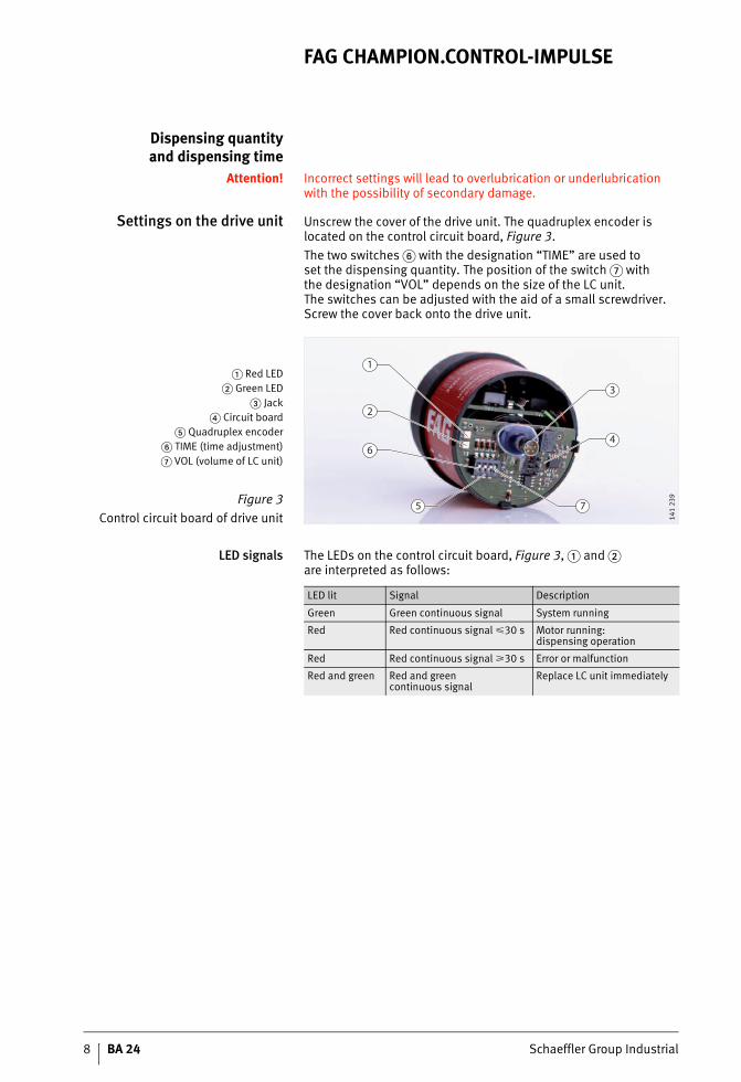
Settings on the drive unit Unscrew the cover of the drive unit. The quadruplex encoder is located on the control circuit board, Figure 3.
The two switches � with the designation “TIME” are used toset the dispensing quantity. The position of the switch � withthe designation “VOL” depends on the size of the LC unit.The switches can be adjusted with the aid of a small screwdriver. Screw the cover back onto the drive unit.
LED signals The LEDs on the control circuit board, Figure 3, � and �are interpreted as follows:
� Red LED� Green LED
� Jack� Circuit board
� Quadruplex encoder� TIME (time adjustment)� VOL (volume of LC unit)
Figure 3
Control circuit board of drive unit
1
2
6
5 7
3
4
141
239
LED lit Signal Description
Green Green continuous signal System running
Red Red continuous signal �30 s Motor running: dispensing operation
Red Red continuous signal �30 s Error or malfunction
Red and green Red and greencontinuous signal
Replace LC unit immediately

Schaeffler Group Industrial BA 24 9
Dispensing table Possible positions of quadruplex encoder
Settingson quadruplex encoder
Attention! As soon as the voltage is applied (15 V DC to 25 V DC, max. 30 V DC), the lubricator releases the set lubricant quantity once only.
The voltage must be applied for at least as long such thatthe dispensing operation is completed after a maximum oftwo minutes.
Before each additional dispensing operation, the voltage must be disconnected for at least 15 seconds and then switched on again.
Quadruplex encoder
Switch 1 and switch 2 “TIME”
Switches 3 and 4 “VOL”
Dispensing quantity in cm3 per impulse,1 cm3 � 0,9 g lubricant
LC60 LC120 LC250
2,11 2,11 2,11
1,06 1,06 1,06
0,53 0,53 0,53
0,26 0,26 0,26

10 BA 24 Schaeffler Group Industrial
FAG CHAMPION.CONTROL-IMPULSE
Initial operation The FAG Motion Guard CHAMPION.CONTROL-IMPULSE is delivered as standard without an LC unit and with a preset dispensing quantity of 0,53 cm3.
Before the lubricator is installed, the lubrication points andthe lubricant feed lines must be sufficiently prelubricated usingthe same lubricant as is contained in the lubricator.
Appropriate 400 g lubricant cartridges or oil containers are available as accessories.■ Support adapters (accessories) should be used for mounting.■ If the lubricator is mounted vertically, it should be secured using
a retaining clip (accessory).
Initial operationAttention! Mount the lubricator using a support adapter or retaining clip.
Always check the settings of the lubricator before initial operation and make corrections as necessary.
Make connections precisely in accordance with the user manual.An incorrect connection can lead to destruction of the electronics.
Mount the lubricator filled with oil vertically, with the outlet facing down. Fit the oil valve. Provide additional sealing of the connectors using a suitable sealing material.
Work steps:■ Check the lubricator for external damage.■ Prelubricate the lubrication point and the feed lines.■ The thread of the LC unit must match the thread of the screw
mounting point (R1/4).■ Connect the power cable in accordance with the PLC circuit
diagrams to the status display in the switch cabinet.■ Check the settings on the encoder.
� Brown cable = power supply (plus)� White cable = Green digital LED (output)
� Blue cable = power supply (minus)� Black cable = Red digital LED (output)
Figure 4
Pin assignment
2
1
3
4
141
220
Schaeffler Group Industrial BA 24 11
■ Remove the closing stopper from the LC unit and screwthe completed lubricator finger tight into the lubrication point. Do not screw in a second time since this can impair theself-sealing effect of the thread.
■ Connect to the power grid.■ After Reset, operation will start with the set pause time.
During operation Check seal integrity and the lubricant fill level as well as the correct position and finger tight screw mounting of all components regularly.
Changing the LC unitAttention! The LC unit must not be opened or refilled under any circumstances.
Only new, completely filled FAG LC units should be used.
Protect the drive system and control circuit board against moisture. The unit should only be changed in dry conditions.
Dispose of old parts in accordance with the applicable regulations.
Once the red and green LEDs light at the same time,the empty LC unit must be replaced immediately.
Work steps:■ Disconnect from the power grid.■ Unscrew the lubricator completely from the lubrication point.■ Unscrew the cover of the drive system.■ Remove the drive system from the LC unit.■ If necessary, set the new size of the LC unit and dispensing
quantity, page 9.■ Position the drive system on the new LC unit,
ensuring that the teeth engage with each other.■ Screw mount the cover of the drive system finger tight
to the LC unit.
Continue the steps in accordance with “Initial operation”, page 10.
Changing the dispensingquantity
Reset function
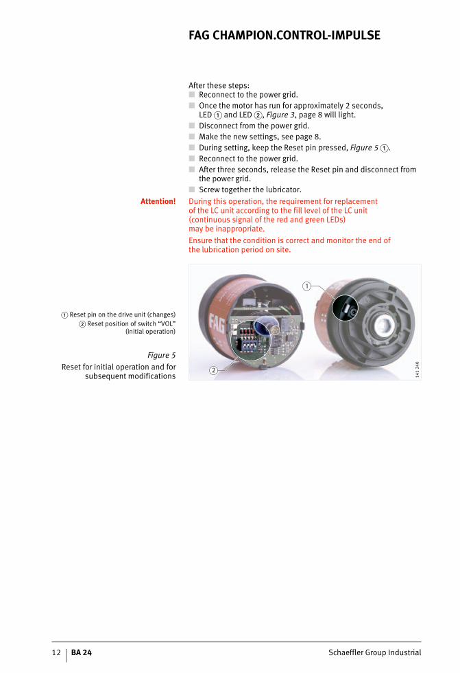
The Reset function switches the lubricator to its base condition by restoring the stored parameters.
The process:■ Disconnect from the power grid.■ Unscrew the lubricator completely from the lubrication point.■ Unscrew the LC unit from the drive unit.■ Set the two switches “VOL” of the quadruplex encoder to
the position “Reset”, Figure 5 �, page 12.
12 BA 24 Schaeffler Group Industrial
FAG CHAMPION.CONTROL-IMPULSE
After these steps:■ Reconnect to the power grid.■ Once the motor has run for approximately 2 seconds,
LED � and LED �, Figure 3, page 8 will light.■ Disconnect from the power grid.■ Make the new settings, see page 8.■ During setting, keep the Reset pin pressed, Figure 5 �.■ Reconnect to the power grid.■ After three seconds, release the Reset pin and disconnect from
the power grid.■ Screw together the lubricator.
Attention! During this operation, the requirement for replacementof the LC unit according to the fill level of the LC unit(continuous signal of the red and green LEDs)may be inappropriate.
Ensure that the condition is correct and monitor the end ofthe lubrication period on site.
� Reset pin on the drive unit (changes)� Reset position of switch “VOL”
(initial operation)
Figure 5
Reset for initial operation and forsubsequent modifications
1
2
141
240
Schaeffler Group Industrial BA 24 13
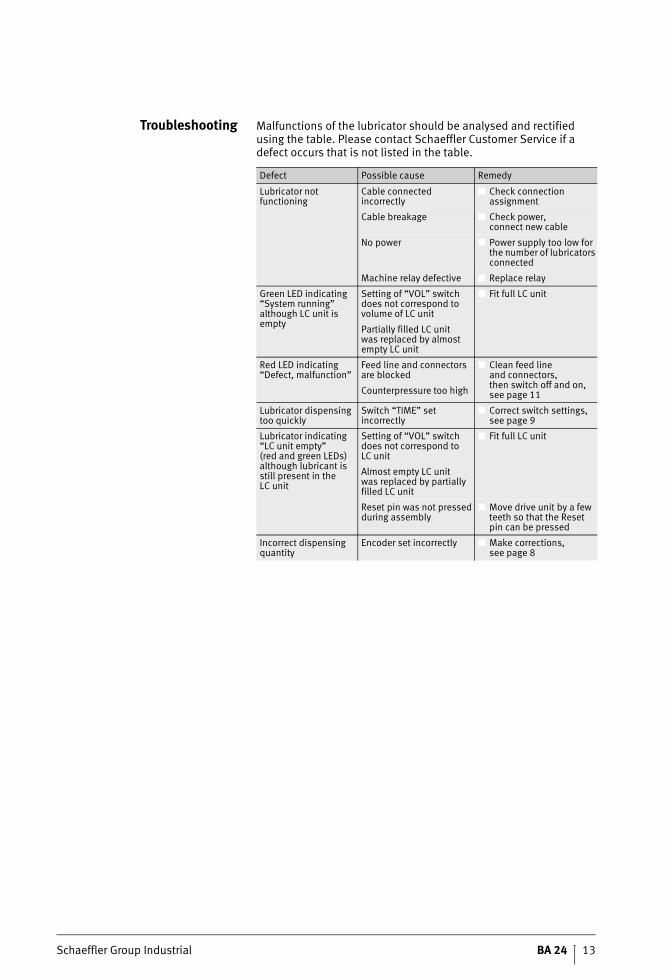
Troubleshooting Malfunctions of the lubricator should be analysed and rectified using the table. Please contact Schaeffler Customer Service if a defect occurs that is not listed in the table.
Defect Possible cause Remedy
Lubricator not functioning
Cable connected incorrectly
■ Check connection assignment
Cable breakage ■ Check power,connect new cable
No power ■ Power supply too low for the number of lubricators connected
Machine relay defective ■ Replace relay
Green LED indicating “System running” although LC unit is empty
Setting of “VOL” switch does not correspond to volume of LC unit
■ Fit full LC unit
Partially filled LC unitwas replaced by almost empty LC unit
Red LED indicating “Defect, malfunction”
Feed line and connectors are blocked
■ Clean feed lineand connectors,then switch off and on, see page 11Counterpressure too high
Lubricator dispensing too quickly
Switch “TIME” set incorrectly
■ Correct switch settings, see page 9
Lubricator indicating “LC unit empty”(red and green LEDs) although lubricant is still present in theLC unit
Setting of “VOL” switch does not correspond toLC unit
■ Fit full LC unit
Almost empty LC unitwas replaced by partially filled LC unit
Reset pin was not pressed during assembly
■ Move drive unit by a few teeth so that the Resetpin can be pressed
Incorrect dispensing quantity
Encoder set incorrectly ■ Make corrections,see page 8

14 BA 24 Schaeffler Group Industrial
FAG CHAMPION.CONTROL-IMPULSE
Accessories and service Accessories and replacement parts must conform to the technical requirements. This is ensured when using original replacement parts from Schaeffler KG.
Accessories
Other accessories available by agreement.
Service The operator has the option of returning the empty lubricator FAG Motion Guard CHAMPION.CONTROL-IMPULSE to Schaeffler KG for:■ disposal of the used parts in an environmentally-friendly
manner,■ replacement of the LC unit,■ setting of the required dispensing quantity.
Description Technical data Ordering designation
Cable with jack plug 5 m ARCALUB-CONTROL.CABLE-5M
Support bracket Thread G1/4, external
ARCALUB.ADAPTER
Retaining clip – ARCALUB.CLIP
Holder with insert – ARCALUB.HOLDER-KIT
Oil valve – ARCALUB.OILVALV-G1/4
400 gram grease cartridgeor oil in container for prelubrication
– Available by agreement

Schaeffler Group Industrial BA 24 15
EU Declaration of Conformity
0001
4100
16 BA 24 Schaeffler Group Industrial
FAG CHAMPION.CONTROL-IMPULSE
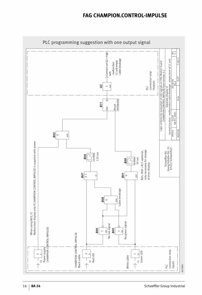
PLC programming suggestion with one output signal
Whe
n us
ing
B02,
I3M
alfu
nctio
n di
spla
y on
ly if
CH
AMPI
ON
CO
NTR
OL
IMPU
LSE
is s
uppl
ied
with
pow
er
l3 Pow
er s
uppl
yCH
AMPI
ON
CO
NTR
OL
IMPU
LSE
3 in in
inv
inv
CHAM
PIO
N C
ON
TRO
L IM
PULS
EBl
ack
cabl
e
I2 Red
LED
Whi
te c
able
No
gree
n si
gnal
No
red
sign
al
PLC
conn
ectio
n st
ripIn
putsI1 G
reen
LED2 in1
1 1
PLC
conn
ectio
n st
ripO
utpu
ts
Set
Rese
t
Cabl
e br
eaka
ge
B01,
B09
+ B
11 o
ptio
nal,
only
nec
essa
ry fo
r sto
rage
of e
rror
dis
play
&
and
&
and
out
on d
elay
on d
elay
latc
hing
rela
y
&
andor
1
120
sec
50 s
ec
Q1
Conn
ect o
ut Q
2 =
high
with
- mal
func
tion
- LC
unit
empt
y- c
able
bre
akag
e
Logi
c sc
hem
e fo
r eva
luat
ion
of L
ED s
igna
ls o
n FA
G M
otio
n G
uard
CH
AMPI
ON
CO
NTR
OL
IMPU
LSE
from
ver
sion
3.1
Sepa
rate
dis
play
of
norm
al fu
nctio
n - m
alfu
nctio
n/ca
ble
brea
kage
- em
pty
leve
l of L
C un
itG
RÖSS
E
MAS
STAB
At/Z
aBL
ATT
Erst
ellt
ZEIC
HN
.NR.
REV.
1 vo
n 1
08.0
1.20
0128
.a1.
1
Scha
effler
KG
Geo
rg-S
chäf
er-S
tr. 2
197
421
Schw
einf
urt
0013
BD
3

Schaeffler Group Industrial BA 24 17
PLC programming suggestion with two output signals
Whe
n us
ing
B13,
I3M
alfu
nctio
n di
spla
y on
ly if
CH
AMPI
ON
CO
NTR
OL
IMPU
LSE
is s
uppl
ied
with
pow
er
CHAM
PIO
N C
ON
TRO
L IM
PULS
EBl
ack
cabl
e
Whi
te c
able
PLC
conn
ectio
n st
ripIn
puts
I1 Gre
en L
EDin1
PLC
conn
ectio
n st
ripO
utpu
ts
or
1
or
1
or
1
Set
Rese
tla
tchi
ng re
layQ
Set
Rese
tla
tchi
ng re
layQ
out1out1
Logi
c sc
hem
e fo
r eva
luat
ion
of L
ED s
igna
ls o
n FA
G M
otio
n G
uard
CHAM
PIO
N C
ON
TRO
L IM
PULS
E fr
om v
ersi
on 3
.1Se
para
te d
ispl
ay o
fno
rmal
func
tion
- mal
func
tion/
cabl
e br
eaka
ge -
empt
y le
vel o
f LC
unit
Scha
effler
KG
Geo
rg-S
chäf
er-S
tr. 2
197
421
Schw
einf
urt
inI2 Re
d LE
D2
l3 Pow
er s
uppl
yCH
AMPI
ON
CO
NTR
OL
IMPU
LSE
3 in
on d
elay
on d
elay
50 s
ec
on d
elay
50 s
ec
120
sec
inv
No
red
sign
al
1 inv
No
gree
n si
gnal
1Ca
ble
brea
kage
&
and
&
and
&
and
Conn
ect o
ut B
04 d
irect
lyw
ith in
put B
13 if
B11/
B12
is n
ot b
eing
use
d
B11,
B12
opt
iona
l
Q1
= a
ctiv
ew
ith
- LC
unit
empt
y
Q2
= a
ctiv
ew
ith- m
alfu
nctio
n- c
able
bre
akag
e
GRÖ
SSE
MAS
STAB
At/Z
aBL
ATT
Erst
ellt
ZEIC
HN
.NR.
REV.
1 vo
n 1
08.0
1.20
0128
.c
1.1
0001
3BD
E

18 BA 24 Schaeffler Group Industrial
FAG CHAMPION.CONTROL-IMPULSE
PLC programming suggestion with three output signals
Whe
n us
ing
B13,
I3M
alfu
nctio
n di
spla
y on
ly if
CH
AMPI
ON
CO
NTR
OL
IMPU
LSE
is s
uppl
ied
with
pow
er
CHAM
PIO
N C
ON
TRO
L IM
PULS
EBl
ack
cabl
e
Whi
te c
able
PLC
conn
ectio
n st
ripIn
puts
I1 Gre
en L
EDin1
PLC
conn
ectio
n st
ripO
utpu
ts
or
1
or
1
or
1
Set
Rese
tla
tchi
ng re
layQ
Set
Rese
tla
tchi
ng re
layQ
out1out1out1
Logi
c sc
hem
e fo
r eva
luat
ion
of L
ED s
igna
ls o
n FA
G M
otio
n G
uard
CH
AMPI
ON
CO
NTR
OL
IMPU
LSE
from
ver
sion
3.1
Sepa
rate
dis
play
of
norm
al fu
nctio
n - m
alfu
nctio
n/ca
ble
brea
kage
- em
pty
leve
l of L
C un
it
Scha
effler
KG
Geo
rg-S
chäf
er-S
tr. 2
197
421
Schw
einf
urt
inI2 Re
d LE
D2
l3 Pow
er s
uppl
yCH
AMPI
ON
CO
NTR
OL
IMPU
LSE
3 in
on d
elay
on d
elay
50 s
ec
on d
elay
50 s
ec
120
sec
inv
No
red
sign
al
1 inv
No
gree
n si
gnal
1Ca
ble
brea
kage
&
and
&
and
&
and
Conn
ect o
ut B
04 d
irect
ly w
ith
inpu
t B13
ifB1
1/B1
2 is
not
bei
ng u
sed
B11,
B12
opt
iona
l
Q1
= a
ctiv
ew
ith
- nor
mal
func
tion
Q2
= a
ctiv
ew
ith
- LC
unit
empt
y
Q3
= a
ctiv
ew
ith- m
alfu
nctio
n- c
able
bre
akag
e
GRÖ
SSE
MAS
STAB
At/Z
aBL
ATT
Erst
ellt
ZEIC
HN
.NR.
REV.
1 vo
n 1
08.0
1.20
0128
.b1.
1
0001
3BE0

Schaeffler Group Industrial BA 24 19
Notes

Schaeffler KG
Postfach 1260
97419 Schweinfurt (Germany)
Georg-Schäfer-Straße 30
97421 Schweinfurt (Germany)
Service Hotline:
Phone +49 2407 9149-99
Fax +49 2407 9149-59
E-mail [email protected]
Internet www.fis-services.de
Every care has been taken to ensure the
correctness of the information contained
in this publication but no liability can be
accepted for any errors or omissions.
We reserve the right to make technical
changes.
© Schaeffler KG · 2009, February
This publication or parts thereof may not
be reproduced without our permission.
BA 24 GB-DMA
TNR
0328
2139
5-00
00 /
BA
24
/ G
B-D
/ 2
0090
2 /
pdf o
nly


![163-B€¦ · DAY 6: RIGA. SIGULDA [Approx. 1 HR] - GAWA [Approx. 1 HR] • TARTU [Approx. 2.5 HRS] • TALLIN [Approx. 2 HRS] (B/--,'D) After your buffet breakfast inside the hotel,](https://img.dokumen.tips/doc/110x75/5f7d4e14a5a2e70a6d3ef87a/163-b-day-6-riga-sigulda-approx-1-hr-gawa-approx-1-hr-a-tartu-approx.jpg)