Embed Size (px)
Citation preview
Faculty of Science & Engineering
School of Engineering and Energy
Control of a Microgrid in
Islanded Mode A thesis submitted in partial fulfillment of the requirements for the degree of Bachelor of Engineering
at Murdoch University, Australia
November, 2012
Student name: Faisal Aljawder (30857509)
Supervisor: Dr. Gregory Crebbin

2 | P a g e
Acknowledgments
First, I would like to express my sincere gratitude to my supervisor, Dr. Gregory Crebbin, for his
skilled guidance, assistance and support during the course of this project. Dr. Crebbin
continually gave me comments and advice that helped me to overcome the difficulties that I
encountered during the implementation of the project. Any time I faced a challenge, Dr.
Crebbin was there to help, despite his busy schedule. Also, I am grateful to all the lecturers and
tutors in the School of Engineering and Energy for their constant support and assistance
throughout my engineering course.
Finally, I would like to thank my family and all my friends back home for their encouragement
and support during the time that I stayed in Australia.

3 | P a g e
Abstract
Economic, technological and environmental issues are affecting the electrical power generation
and transmission. A microgrid is a new technique that can provide electricity with less impact
on the environment and is, at the same time, economically attractive. Basically, the concept of
a microgrid is to use small-scale renewable generator sources instead of upgrading the main
utility grid. This thesis presents a complete microgrid model and investigates the operational
behaviour by using simulation software. The proposed control strategy described in this thesis
is based on controlling the generators’ output power to match the required power from the
loads. This can be achieved by using the active vs. reactive power droop control method, which
will make each generator independently controlled. In other words, the generators’ output will
adjust without requiring any data from other microgrid components. The main advantage of
this technique is it increases the security and stability of the system by providing a supply of
backup energy for the load in case one of the distributed generators shuts down.
If there is no synchronous machine to balance between supply and demand under microgrid
disconnected mode, the inverters must take the responsibly of controlling the voltage and
frequency. The voltage source control method that uses the P/Q Droop control technique is
used in this thesis. The results proved that the P/Q droop control method is able to provide the
loads with the required power and at the same time maintain the voltage and frequency within
acceptable limits during island operation mode.

4 | P a g e
Contents
Abstract ........................................................................................................................................................ 3
1.0 Introduction ............................................................................................................................................ 8
1.1 Microgrid Definition ............................................................................................................................ 8
1.2 Thesis Objective .................................................................................................................................. 8
1.3 Thesis Outline ...................................................................................................................................... 9
2.0 Background ........................................................................................................................................... 10
2.1 The need of Microgrids ..................................................................................................................... 10
2.2 Main Component .............................................................................................................................. 11
2.2.1Distribution Generator (DG) ....................................................................................................... 11
2.2.2 Loads .......................................................................................................................................... 14
2.2.3 Distribution Storage (DS) ........................................................................................................... 15
2.2.4 Interconnection switch .............................................................................................................. 16
2.2.5 Control system. .......................................................................................................................... 16
2.3 Microgrid Operation ......................................................................................................................... 17
2.3.1 Grid-connected mode ................................................................................................................ 17
2.3.2 Island mode ................................................................................................................................ 17
2.3.3 Transition between grid-connected and islanded mode ........................................................... 19
2.4 Protection ......................................................................................................................................... 19
3.0 Principle of Operation and Control ...................................................................................................... 22
3.1 DG control configuration .................................................................................................................. 22
3.1.1 Unit Power Control Configuration (UPC) ................................................................................... 22
3.1.2 Feeder Flow Control Configuration (FFC)................................................................................... 22
3.1.3 Mixed control Configuration ...................................................................................................... 23
3.2 Hierarchical Control of Microgrids .................................................................................................... 23
3.2.1 Primary control .......................................................................................................................... 24
3.2.2 Secondary control ...................................................................................................................... 24
3.2.3 Tertiary control .......................................................................................................................... 25
3.3 DG Control ......................................................................................................................................... 26
3.3.1 PQ inverter control .................................................................................................................... 26

5 | P a g e
3.3.2 Voltage source inverter control ................................................................................................. 26
4.0 Proposed Control strategy ................................................................................................................... 27
4.1 VSI Control Method........................................................................................................................... 27
4.1.1 P and Q Calculation .................................................................................................................... 28
4.1.2 Decoupling ................................................................................................................................. 29
4.1.3 P versus Frequency Droop ......................................................................................................... 29
4.1.4 Q versus Voltage Droop ............................................................................................................. 31
5.0 Simulation Platform ............................................................................................................................. 34
5.1 Matlab Simulink ................................................................................................................................ 34
5.2 Implementation of the Tested Microgrid ......................................................................................... 35
5.3 System Modeling............................................................................................................................... 37
5.3.1 Utility Grid .................................................................................................................................. 37
5.3.2 DG............................................................................................................................................... 37
5.3.3 Load ............................................................................................................................................ 38
6.0 Simulation Results and Discussion ...................................................................................................... 40
6.1 Simulation scenario ........................................................................................................................... 40
6.2 Results ............................................................................................................................................... 41
7.0 Conclusion ............................................................................................................................................ 45
7.1 Thesis conclusion .............................................................................................................................. 45
7.2 Suggestion for future work ............................................................................................................... 45
8.0 References ............................................................................................................................................ 47
9.0 Appendix ............................................................................................................................................... 49
9.1 Appendix A (System Parameter) ....................................................................................................... 49
9.2 Appendix B (DG Controller Design) ................................................................................................... 50
9.3 Appendix C (DG Controller Test) ....................................................................................................... 52
9.4 Appendix D (Utility Grid) ................................................................................................................... 55
9.5 Appendix E (Wind Turbine) ............................................................................................................... 56

6 | P a g e
List of Figures Figure 1 Main Components ........................................................................................................................ 11
Figure 2 Elementary diagram of an AC generator and exciter ................................................................... 12
Figure 3 Small-scale Synchronous Generator (3MW) ................................................................................ 12
Figure 4 Solar panels pointed at the sun to absorb solar energy .............................................................. 13
Figure 5 Wind turbines ............................................................................................................................... 13
Figure 6 Internal structure of a wind turbine ............................................................................................ 14
Figure 7 Recharchable Batteries ................................................................................................................ 15
Figure 8 Capacitor Bank .............................................................................................................................. 15
Figure 9 Flywheel energy storage ............................................................................................................... 16
Figure 10 Unit output power control (UPC) ............................................................................................... 22
Figure 11 Feeder Flow Control (FFC) .......................................................................................................... 23
Figure 12 Hierarchical Control levels of a Microgrid .................................................................................. 23
Figure 13 Secondary control: restoration and synchronization ................................................................. 24
Figure 14 Tertiary control and the synchronization control loop .............................................................. 25
Figure 15 DGs control technique ................................................................................................................ 28
Figure 16 Active and Reactive Power Calculation Block ............................................................................. 28
Figure 17 Active and Reactive Power Decoupling Block ............................................................................. 29
Figure 18 Active Power Vs Frequency Droop Characteristic ...................................................................... 30
Figure 19 Block Diagram of the Active Power Droop . ................................................................................ 31
Figure 20 Block Diagram of the Reactive Power Droop . ............................................................................ 31
Figure 21 Reactive Power Vs Voltage Droop Characteristic . ..................................................................... 32
Figure 22 Microgrid Design ......................................................................................................................... 35
Figure 23 Implementation of Microgrid Structure in Simulink ................................................................... 36
Figure 24 Utility Grid Model........................................................................................................................ 37
Figure 25 Distribution Generator ................................................................................................................ 38
Figure 26 Implementation of Droop Control in Simulink ............................................................................ 38
Figure 27 Loads model ................................................................................................................................ 39
Figure 28 Main grid power (kW) ................................................................................................................. 41
Figure 29 DG output power (kW) ................................................................................................................ 41
Figure 30 System frequency (Hz) ................................................................................................................ 42
Figure 31 Common bus voltage (pu) ........................................................................................................... 42
Figure 32 Critical Load 1 Power (W) ............................................................................................................ 43
Figure 33 Critical Load 2 Power (W) ............................................................................................................ 43
Figure 34 Non-critical load power (W) ........................................................................................................ 44
Figure 35 VSI three phase control model ................................................................................................... 50
Figure 36 Implementation of Droop Control in Simulink ............................................................................ 51
Figure 37 Circuit Structure .......................................................................................................................... 52
Figure 38 System frequency (Hz) ................................................................................................................ 53
Figure 39 Common Bus Voltage (pu) .......................................................................................................... 53
Figure 40 DG1 Active and Reactive Powers (W) ......................................................................................... 54

7 | P a g e
Figure 41 Loads Active and Reactive Powers (W) ....................................................................................... 54
Figure 42 Utility Grid model ........................................................................................................................ 55
Figure 43 Substation Voltage (v) ................................................................................................................. 55
Figure 44 Wind Turbine model in Simulink ................................................................................................. 56
Figure 45 Wind Turbine output power (W) ................................................................................................ 56

8 | P a g e
Chapter 1
1.0 Introduction
1.1 Microgrid Definition
A microgrid can be described as a series of small-scale electrical power generators that operate
in parallel with the utility grid to supply a number of loads. A microgrid is a low voltage network
that connects local generator units with the loads. The local generators are called microsources
or distributed generators and they can be either conventional power generators or renewable
sources. These generators are normally located near the loads. Microgrid technology provides
high-quality electrical power to the local loads. Also, it maintains and sustains the power to the
critical loads in case of any faults or disturbance in the main grid. A microgrid can operate either
in parallel with the main grid or in a disconnected mode. The disconnected mode (or islanding
mode) operates when a disturbance occurs in the main grid, and serves to prevent any
interruption in the power supply received by the local loads. When the disturbance no longer
exists on the main grid, then the microgrid can be returned to its normal operating mode,
which is the grid-connecting mode [6].
A microgrid consists of distributed generators (DGs), loads, distributed storage (DS),
interconnection switch and control system. These components will be discussed in the next
chapter.
1.2 Thesis Objective
The main aim of this thesis is to investigate a strategy to control microgrids. The approach used
in this thesis is that of taking over voltage and frequency control when the microgrid is
operating in islanding mode. More generally, this thesis will explore the microgrid concept, such
as the purpose of a microgrid, its main components, protection issues and principles of
operation and control. Overall, the objectives of this study are summarised in the following
points:
to explore the importance of emerging microgrid technology
to understand the concept of a microgrid and its main components
to describe and discuss different configurations of the DG controller
9 | P a g e
to design and implement a complete model of a microgrid using Matlab/Simulink software
to verify the efficiency of the P/Q droop control method in controlling the DG behaviour and maintaining stability in the system
1.3 Thesis Outline
Chapter 2: Provides a brief background to the microgrid concept, including its structure,
main components, protection issues and modes of operations.
Chapter 3: Presents the DG control configuration and the hierarchical control of microgrids.
Chapter 4: Discusses the proposed control strategy that will be used in the simulation.
Chapter 5: Shows the tested microgrid structure as well as implementation of the system in
simulation software.
Chapter 6: Presents and discusses the simulation results.
Chapter 7: Summarises the main outcomes of the thesis and provides some suggestions for
future work.

10 | P a g e
Chapter 2
2.0 Background This chapter introduces the concept and the need for microgrids. Also, the main components of
a microgrid are described. In addition, this chapter includes a discussion on how a microgrid
operates and the issues that need to be considered. A discussion on the protection of a
microgrid is presented at the end of the chapter.
2.1 The need of Microgrids As of yet, most people around the world do not realise the importance and benefits of
implementing the microgrids that exist now. In fact, using this technology will definitely
improve the reliability and reduce the cost and environmental impacts of the electrical power
generation.
Ordinarily, a microgrid operates in parallel with the main grid, but sometimes it can work
independently. Should any failures occur in the main grid, then microgrids can provide reliable
and high-quality power for the local loads. However, in this situation, the microgrid may only
deliver power to the critical loads. In addition, the microgrid improves power quality as well as
reliability. A book published by the Institution of Engineering and Technology in the United
Kingdom discussed the impacts of microgrids. The writers present many reasons why they
believe microgrids can improve power quality. These include decentralisation of supply, better
matches of supply and demand, reduction in the impact of large-scale transmission and
minimisation of downtimes [7]. Therefore, microgrids can be considered as a reliable
technology to provide electricity for local loads.
The growth of electricity demand has increased significantly in the last few years, raising
economic issues and becoming an important element in electrical power generation. A
microgrid has a positive impact in reducing costs. First of all, a microgrid can reduce the loss in
the power transmission lines by locating the distribution generators near the loads. Further,
using a microgrid will avoid the extension of the main grid if the demand increased, which is
one of the major factors of power supply cost, especially when the affected geography is harsh
and comprises mountains, hills, etc.
Obviously, microgrid technology will have less environmental impact than the implementation
of a large conventional power generator. This is because the renewable energy sources that are
used in microgrids have zero or low emissions. Another benefit of microgrids mentioned in the
same article in the previous paragraph is that “Physical proximity of customers with

11 | P a g e
microsources may help to increase the awareness of customers towards judicious energy
usage” [7]. In other words, the close location of microsources to the local loads will increase the
awareness of the importance of saving energy.
2.2 Main Components
The five main components of a microgrid consist of the DG, loads, DS, interconnection switch
and control system. These components will be briefly described in the next sections. As we can
see in the figure below, the main grid is connected to a step-down transformer to provide the
same level of voltage as that produced from the distributed generators. In addition, a switch
links the utility grid and the microgrid. This interconnection switch is responsible for isolating
and reconnecting the microgrid to the utility grid. The diagram below represents a simple
microgrid structure.
Figure 1 Main Components [15]
2.2.1Distributed Generator (DG)
Distributed generators or microsources are the units that provide power in the microgrid. These
are normally placed near the loads. These energy sources can be either conventional or
renewable energy units. As stated earlier, distributed generators are normally placed near the
12 | P a g e
loads, which will obviously minimise the power transmission losses between the generators and
the loads in the microgrid. Also, some distributed generators can provide heat energy by
recovering its excess power of operation. Thus, the overall efficiency of the system will increase
and the operation cost of the generator will decrease.
The main difference between conventional and most renewable distributed generators is that
the renewable energy sources are considered as current sources; however, most conventional
power generators are voltage sources. In other words, the output voltage can be controlled in
conventional generators such as the synchronous and induction generator [11].
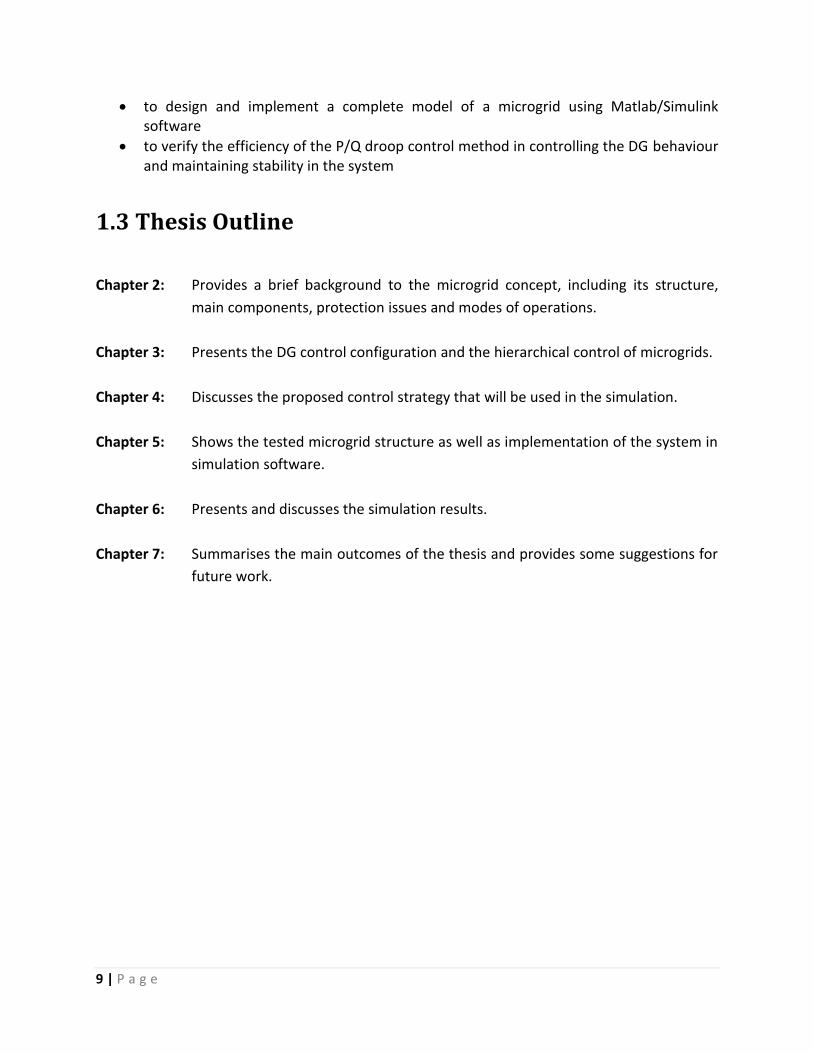
2.2.1.1 Conventional energy sources
A conventional energy generator can be classified as a dispatchable power unit. The output
power of these generators is directly supplied to the grid. This is in contrast to renewable
energy sources, which require inverters or rectifier devices to convert the output power into AC
to match the grid’s requirement. In conventional generators, as shown in figure 3, the voltage
can be determined by controlling the speed of the motor.
2.2.1.2 Renewable energy sources
Basically, renewable energy is the energy that comes from renewable sources such as the sun,
wind, tide and waves. The renewable energy power units such as solar panels and wind
turbines require powered electronic devices to convert the power into AC power to feed into
the grid. As was stated in the beginning, we will mainly focus on solar and wind power
generation.
Figure 3 Elementary diagram of an AC generator and exciter [13] Figure 2 Small-scale Synchronous Generator (3MW) [13]
13 | P a g e
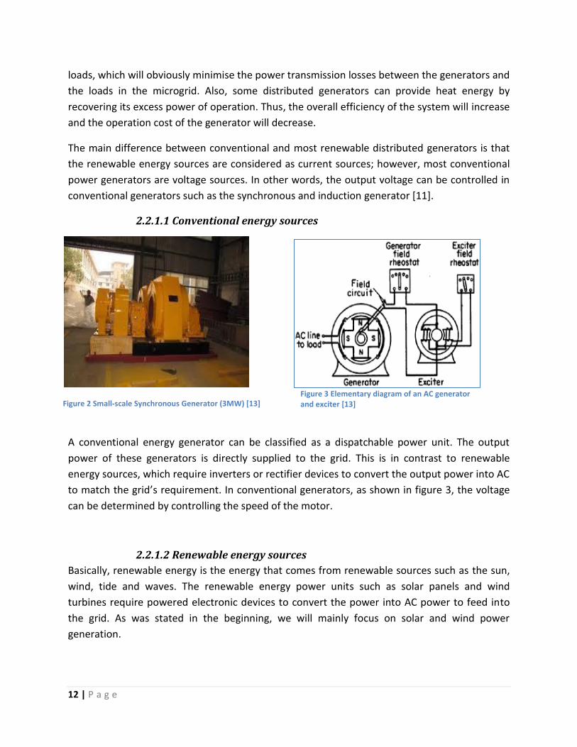
Solar panel
A solar panel (also known as a PV array) is a group of photovoltaic cells connected together to
generate electricity from the energy in sunlight (see figure 4). A solar panel is normally linked to
an inverter because the generated power from the panels is direct current (DC). The PV inverter
convert the DC output of the PV array into a utility frequency alternating current (AC) .In most
applications, the PV is also connected to a battery bank to store the energy excess and restore
it when needed. When choosing the type of panel, many issues need to be considered,
because there are different types of panels and each one has its own specification and uses.
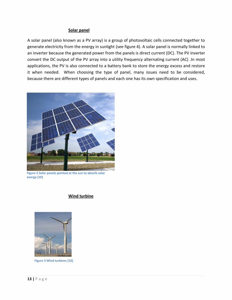
Wind turbine
Figure 3 Wind turbines [10]
Figure 2 Solar panels pointed at the sun to absorb solar energy [10]
14 | P a g e
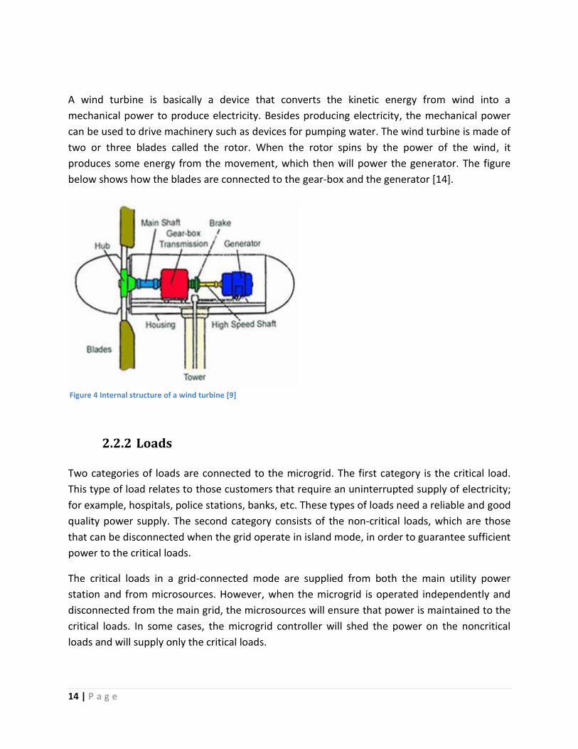
A wind turbine is basically a device that converts the kinetic energy from wind into a
mechanical power to produce electricity. Besides producing electricity, the mechanical power
can be used to drive machinery such as devices for pumping water. The wind turbine is made of
two or three blades called the rotor. When the rotor spins by the power of the wind, it
produces some energy from the movement, which then will power the generator. The figure
below shows how the blades are connected to the gear-box and the generator [14].
2.2.2 Loads
Two categories of loads are connected to the microgrid. The first category is the critical load.
This type of load relates to those customers that require an uninterrupted supply of electricity;
for example, hospitals, police stations, banks, etc. These types of loads need a reliable and good
quality power supply. The second category consists of the non-critical loads, which are those
that can be disconnected when the grid operate in island mode, in order to guarantee sufficient
power to the critical loads.
The critical loads in a grid-connected mode are supplied from both the main utility power
station and from microsources. However, when the microgrid is operated independently and
disconnected from the main grid, the microsources will ensure that power is maintained to the
critical loads. In some cases, the microgrid controller will shed the power on the noncritical
loads and will supply only the critical loads.
Figure 4 Internal structure of a wind turbine [9]

15 | P a g e
The non-critical loads are the loads that do not require power all the time or are able to
function without power for a temporary period. For example houses, clubs, restaurants and
libraries are able to survive without electricity. In the case of disconnected mode, the microgrid
controller will give priority to the critical loads, and if there is any excess power, only then will it
be fed to the non-critical loads.
2.2.3 Distributed Storage (DS)
DS are used to store excess energy in the microgrid. DS is a very important component of the
microgrid because it is responsible for providing power in case of a shortfall in supply from the
renewable energy units or if the microgrid is operating in islanding mode. DS can be compared
to the spinning reserve in main power generators.
Some DS needs a power converter in order to supply electricity to the grid. The installed
converter must be a bi-directional converter. The reason for using this type of converter is to
supply power to the storage device when there is an excess of energy in the microgrid and to
feed the microgrid when there is a shortfall. Basically, the storage devices can be considered as
extra or backup generators.
The three main types of DS are batteries, flywheels and capacitor banks. The figures below
show the layout of each one. In fact, each type of these devices has its own characteristics and
design. For instance, a flywheel is similar to batteries in terms of having a fixed energy capacity.
Furthermore, their storage times are rated by the number of minutes of power that can be
provided. However, some differences do exist between them. For example, the flywheel output
is AC and batteries provide DC, plus the flywheel has a faster response time than batteries. The
capacitor has a higher voltage capacity than batteries. However, it stores less energy than
either batteries or the flywheel. Furthermore, capacitors are expensive and nowadays no
commercial manufacturers produce large-scale capacitor systems [3]. Therefore, batteries and
flywheels are more attractive to use as DS in microgrids.
Figure 8 Capacitor Bank [8] Figure 7 Recharchable Batteries [8]

16 | P a g e
Figure 5 Flywheel energy storage [8]
2.2.4 Interconnection switch
An interconnection switch is basically a switch that can be used to disconnect and isolate the
microgrid from the main grid in case of any faults or shortage in the main grid. It is also used to
reconnect the microgrid to the main grid when the problem no longer exists. In this thesis, we
will deal with the Point of Common Coupling (PCC), which is one of the most commonly used
interconnection switches in microgrids.
A PCC is a static switch used to isolate and reconnect the microgrid from the main grid. The PCC
is a very important element in the microgrid because it protects the local loads from any
unexpected or unacceptable power that may damage the loads. For example, a PCC will isolate
the microgrid if the frequency in the main grid is not within the acceptable limits. Also, this
action will be invoked if there is a fault that will lead to a high current being directed towards
the microgrid. Therefore, the coupling PCC is a compulsory element in the microgrid.
2.2.5 Control system
The main responsibility of the control system is to ensure that the voltage and frequency are
within the acceptable limits. Many existing strategies can be used to achieve this goal. This
thesis will investigate how the primary control can regulate the power in the microgrid for
island operation mode.
The correct implementation of the control system has many benefits for the microgrid; such as,
reducing emissions by regulating and generating the exact amount of needed power. Besides
that, the control system improves the microgrid’s safety when switching between connected
17 | P a g e
and disconnected modes. Therefore, it is very important to ensure that the control system of
the microgrid is operating in the right way.
2.3 Microgrid Operation
The microgrid can operate in either grid-connected or islanding mode. This section will describe
both modes and the effects each has on the microgrids. Also included is a discussion of the
behaviour of the microgrid at the time of transition between the two operation modes. This
section will also highlight some main issues regarding the island mode of operation, as this
thesis will focus mainly on the behaviour of a microgrid under the disconnected mode.
2.3.1 Grid-connected mode
A microgrid is normally operated under grid-connected operation mode. In this mode, the
microgrid loads receive power from both the utility plant and the microgrid DGs. The microgrid
voltage and the frequency in grid-connected mode are regulated by the utility grid voltage and
frequency. In fact, DGs are controlled through voltage and frequency regulation for real and
reactive power generation using a communication bus. More details and discussion on
microgrids under grid-connected mode operation can be found in [12].
2.3.2 Islanding mode
The interconnection switch disconnects the microgrid from the main utility grid in case of any
fault or disturbance. In this situation, the microgrid will operate autonomously and will take the
responsibility to supply the loads. In addition, the microgrid must ensure that the voltage and
frequency are within the acceptable limits.
The microgrid can be switched to operate under island mode in the following two scenarios.
The first scenario is the preplanned island operation. If any such events as general faults or
maintenance, for example, occur in the utility grid, then the microgrid has to start operating
autonomously. The second scenario is the unplanned island operation. This scenario represents
the event when there is a blackout due to a disconnection of the main grid, which the microgrid
can detect by using appropriate algorithms [12].
DGs are responsible for regulating voltage and frequency in the microgrid. When a microgrid
operates in islanding mode, a small deviation may occur from the nominal voltage and
frequency. Therefore, DGs are required to maintain the stability of the system by reducing this
variation. This can be done by implementing the appropriate control technique on the DG units,
which can balance the system [12]. The following section discusses the main issues of microgrid
operation under island operation.

18 | P a g e
Issues with Microgrids in Islanding Mode
Many issues need to be taken into account when a microgrid is operated in disconnected mode.
The following points are adopted from an article published by the Institute of Electrical and
Electronics Engineers (IEEE), which summarised the main issues of microgrid island mode
operation [14].
1) Voltage and Frequency Control
Unlike the grid-connected operation where the voltage and frequency of the microgrid are
determined from the utility grid, under the island mode, the voltage and frequency of the
microgrid are controlled by adjusting the voltage and frequency of one or more microsources. It
is very important to keep the frequency within the acceptable limits. Otherwise, if it falls
outside the limits, then the load may temporarily shed.
2) Balance between Supply and Demand
There are three possible operation conditions of power balance between supply and demand in
islanding operation mode: supply surplus, supply shortage and equilibrium. In case of supply
surplus, the decrease of power generation in microsources can be used to balance the system.
However, in case of supply shortage, then the load-shedding technique on the non-critical loads
can be used to keep the system in balance [2]. Furthermore, if the microgrid is exchanging
power with the main grid before switching to islanding mode, then the secondary control
actions should be applied to make sure the initial power is balanced in the microgrid after a
sudden fluctuation in supply or demand [14].
3) Power Quality
The power quality of the microgrid should always be in a good condition. The microgrid should
take the responsibility to preserve an adequate power quality with a sufficient supply of
reactive power in order to minimise voltage sags.
4) DG Issues
There are many issues that relate to the distributed generators in the disconnected mode. For
example, some generators have a delayed response when implementing secondary control for
voltage and frequency. Moreover, the microgrid has no spinning reserve like the utility grid, but
it has DS and DG with built-in battery banks that can be considered to act as a microgrid
spinning reserve. The inverter reacts quickly to a fast demand signal and adjusts the power flow
levels [14].
19 | P a g e
5) Communication among Microgrid Components
The implementation of a proper communication infrastructure between microgrid components
is a very important issue when selecting the control approach for an islanding microgrid.
6) Planned Microgrid Islanding
Beside the above factors, the microgrid should be prepared for planned islanding. It is very
important to include this aspect in the microgrid because it is responsible for maintaining the
continuity of power supply during planned outages [14].
2.3.3 Transition between grid-connected and islanded mode
The transition time is when the microgrid switches its operation mode. To provide a high
reliability level, the restoration time must be minimised as much as possible. When the
microgrid is disconnected from the utility grid, the interconnection switch has to adjust and
modify the power reference to match with the nominal value. Moreover, the maximum
deviation allowed for the voltage and frequency is 5% and 2% respectively. If the
interconnection switch recognises that the fault or disturbance in the utility grid no longer
exists, then it will reconnect the microgrid. However, certain issues need to be considered
during the restoration process, such as balancing the reactive power, starting sequence and
coordination of DGs [16].
2.4 Protection Microgrid protection is an essential requirement in implementing and maintaining the
microgrid operation. The microgrid has to protect its components in both grid-connected and
island operation mode against all types of faults.
As was stated in the beginning of this chapter, the interconnection switch or PCC is responsible
for isolating and reconnecting the microgrid with the utility grid. Therefore, the PCC has to
disconnect the microgrid when any type of fault occurs in the grid. Professor Hassan Nikkhajoei
has published many articles discussing the issue of protecting the microgrid, and he stated that
“The philosophy for protection is to have the same protection strategies for both islanded and
grid-connected operation. The static switch is designed to open for all faults”[17].
The distributed generator changes its properties significantly when the microgrid switches to
island operation. Moreover, the type of the DG needs to be considered as well. For example,
induction and synchronous generators have different protection techniques. The output of the
DG is often unpredictable, which causes the grid behaviour to change constantly in response to

20 | P a g e
a fault occurrence. In fact, protection of the DG depends on the state of the main grid and the
protection parameters have to be constantly updated. The following points were adopted from
Johan [18], who talks about some protection issues related to installing DGs in a microgrid [18].
Selectivity
“System protection is selective if only the protection device closest to the fault is triggered to
remove or isolate the fault” [18]. In normal operation or even when a fault occurs, if there are
no DGs in the network, the power flows in one direction. Therefore, the system can be
protected by applying time grading to the overcurrent relays. However, this technique is not
applicable when there is a DG in the system, because there is a possibility that one of the DGs
will be disconnected when a fault occurs at a neighbouring DG. The DG’s protective relay will
contribute to any short circuit current flowing through a fault at a neighbouring DG. In fact, the
tripping current of the protective devices must be assigned between maximum current of the
load and the minimum fault current. Also, the parameters of the protection devices should be
continuously updated because the output power of DGs sometimes becomes irregular.
Protective Disconnection of Generators
DGs should be protected against several expected events, such as over and under-voltages,
unusual frequencies, harmonic distortions and short-circuit events. The protection mechanism
of the DGs has to select a different time delay, which in fact will depend on the location of the
fault. In case of faults occurring in the microgrid, the protection devices that are located
between the DG and the fault should have the ability to disconnect the DG from the grid. The
disconnection should occur very fast, especially when the fault event is located near the DG.
Microgrid island mode operation
Sometimes the microgrid needs to isolate the DGs to prevent unintentional islanding. The
purpose of such is not just to protect the grid or the DG, but rather for the safety and
protection of any individuals who might be seated close to or touching these DGs at that
moment. The microgrid operation under disconnected mode should be considered as an
alternative option, even though the use of island mode will increase the reliability of microgrids
[18].
Single-Phase Connection
Some DGs in the microgrid can inject single-phase power into the grid, which will affect the
balance of the three-phase electric current. The injection of single-phase power will
consequently increase the current in the neutral conductor and stray currents in the earth. This

21 | P a g e
current should be minimised in order to avoid any overloading and to ensure the safety of
individuals [18].

22 | P a g e
Chapter 3
3.0 Principles of Operation and Control
3.1 DG control configuration
3.1.1 Unit Power Control Configuration (UPC)
The main purpose of this configuration is to control the power injected by the DGs at a desired
value [19]. In UPC configuration, the DGs are regulated to provide a constant output power,
which means if the microgrid loads are increased at any time, then the utility grid is responsible
for supplying the extra demands. As can be seen in Figure 10, the voltage at the connection
point and the DG output current are measured in order to calculate the amount of power that
needs to be injected into the generator controller.
However, when the microgrid operates in island mode, the droop controller takes over the DG
units to balance the power in the microgrid by ensuring that the voltages and the frequencies
of the DGs are the same [15]. The droop control method will be discussed in detail in chapter
four.
Figure 6 Unit output power control (UPC) [19]
3.1.2 Feeder Flow Control Configuration (FFC)
The purpose of the FFC configuration is to ensure that the active power flow remains constant
at the connection point, as shown in Figure 11. This can be done by controlling the output
power of the DG. When the load increases during grid-connected mode, the DG supplies and
covers the extra demands in the loads, in contrast to UPC, where the main grid is responsible

23 | P a g e
for that task. Therefore, the output power of the DG will depend on the load. In other words,
the supply from the utility grid will remain constant even if the microgrid loads are increased.
Consequently, the FFC configuration causes the microgrid to be seen from the utility side as a
true dispatchable load. Again, in disconnected operation mode, the droop controller takes the
responsibility for controlling the DG [20].
Figure 7 Feeder Flow Control (FFC) [19]
3.1.3 Mixed Control Configuration
Mixed control is based on combining the UPC and FFC configurations together. Basically, some
DGs regulate their active power and some others regulate the feeder power flow [20].
Depending on the needs, each microsource will control either the power or feeder flow. The
main benefit of using this configuration is to improve the overall efficiency of the system.
3.2 Hierarchical Control of Microgrids A microgrid has some similarity in terms of operation control to the utility grid. Figure 12 shows
the main three control levels in a microgrid, which will be explained in the next few paragraphs.
Figure 8 Hierarchical Control levels of a Microgrid [12]

24 | P a g e
3.2.1 Primary control
The primary control can be considered as the first level in the control system of a microgrid.
Basically, the concept of this level is to control the output of each microsource. The primary
control, also called decentralised control, normally uses the droop control method. This method
is used to emulate physical behaviours of a synchronous machine that make the microgrid more
stable [12]. In addition, the droop control can be described as a method that is used to share
load between converters. In grid-connected mode, all the microsources must have the same
droop function. The droop control method is explained in detail in Chapter four.
3.2.2 Secondary control
As can be seen in figure 12, the secondary control is the second level in the hierarchical control
levels in a microgrid. This control level has the responsibility of removing any steady state error
that might be produced from the primary control. In other words, the secondary control
maintains and improves the power quality in a microgrid. Unlike the primary control, this
control needs communication from and to the microsources. The supervisor system (see Figure
13) sends signals to the DGs’ inverters by using low bandwidth communication in order to
restore the microgrid voltage to the nominal value. In addition, when the microgrid switches
from island to grid-connected mode, the secondary control has the responsibility to
synchronise the microgrid voltage and frequency to the utility grid [12].
Figure 9 Secondary control: restoration and synchronization [12]
To maintain the stability within the microgrid, the secondary control reduces the voltage and
frequency deviation that has been produced by the primary control. This can be done by

25 | P a g e
updating the setpoint of the DGs voltages and frequencies to coordinate the microgrid status.
To sum up, secondary control is an important factor for preserving a safe and stable operation
in the microgrid [21].
3.2.3 Tertiary control
Tertiary control has different responsibilities from primary or secondary control. This level of
control is more concerned with global issues, such as improving overall power efficiency. The
tertiary control regulates and decides the amount of power that can be imported or exported
between the microgrid and the utility grid. The principle of operation of the tertiary control is
based on adjusting the inverter’s references in the microgrid to ensure optimisation of the
power flows.
Importing and exporting energy from the microgrid depends on economic issues concerning
whether it is worthwhile to sell or buy power. The decision, which is made by the tertiary
control, is based on various economic data and studies [12].
Figure 10 Tertiary control and the synchronization control loop [12]
26 | P a g e
3.3 DG Control A variety of designs can be implemented in order to control the operation of DGs in a microgrid.
As this thesis discusses the use of renewable energy sources in the microgrid, therefore, this
section will briefly discuss the control strategies that can be used to control the renewable
energy sources. These types of generators use inverters to communicate and interface with the
grid. Accordingly, to maintain the stability in the system, the inverters of the DGs need to be
controlled. The following gives a description of two types of control strategies that may be used
to operate the inverter.
3.3.1 PQ inverter control
The PQ inverter control method is based on supplying a given active and reactive power
setpoint. This control can only be used when the microgrid is operating under grid-connected
mode. The PQ inverter control operates by injecting into the grid the power available at its
input. The setpoint of the DGs is predefined in the controller and in most cases is 100% of the
available generator output power. The PQ control takes the voltage and frequency of the main
grid as a reference to control the DGs’ output. More information about the PQ inverter control
can be found in [14, 15, 22].
3.3.2 Voltage source inverter control
Voltage source inverter control (also called VSI) has similar behaviours to a synchronous
machine, thus controlling the voltage and frequency of the AC system. Normally, the VSI
method is used to control the DGs under island operation mode. Basically, the purpose of VSI is
to supply the load with a pre-defined value of voltage and frequency where the real and
reactive output power of the VSI is dependent on the load [14]. As has been stated earlier, this
thesis will study the behaviour of microgrids by using the VSI method to control the DGs. A
discussion and implementation of this control strategy is presented in Chapter 4.

27 | P a g e
Chapter 4
4.0 Proposed Control strategy
As has been stated in the objectives, this thesis will investigate the behaviour of microgrids
under disconnected mode. This chapter proposes a control strategy to support this
investigation. In order to do this, it is very important to know the required function and the
scenario that will be used on the microgrid.
The control strategy that may be used in a microgrid under island operation mode is different
from the one used under grid-connected mode. When the PCC disconnects the microgrid, then
the voltage and frequency are no longer controlled by the utility grid. Therefore, the voltage
and frequency of the microgrid will need to be controlled internally. One way to do this is by
implementing a master controller. The operation principle of this controller is to receive and
analyse the data from both the loads and the PCC and then send an order to the DGs to adjust
their outputs to meet the amount of power needed by the loads. In fact, there are some
disadvantages of using a master controller in a microgrid such as, the system may shut down at
any time in case of a breakdown of the master controller. Therefore, the master controller
technique has been eliminated [15]. A second type of control strategy, which is going to be
used in this thesis, is to assign a controller to each DG. This will cause DGs to be independently
controlled. In other words, the output of DGs will be adjusted without requiring any data from
other microgrid components. The main advantage of this technique is it increases the security
and stability of the system by providing backup energy for the load in case one of the DGs shuts
down. The control principle of this technique is similar to the control of a synchronous machine.
The inverter is an essential element that needs to be controlled to maintain the stability of the
system. The output of the renewable energy units can be controlled from their inverters. The
design of this controller is based on determining the voltage and frequency needed by using the
“P/Q droop control method.” [12, 20].
4.1 VSI Control Method
If there is no synchronous machine to balance supply and demand, the inverters must take the
responsibility of controlling the voltage and frequency. The voltage source control method that
uses the P/Q Droop control technique is shown in Figure 15. This method is adopted from
[12,15]. The first two blocks, which are labelled as Q and P Calculation, are used to calculate the
active and reactive powers injected by the inverter. This measuring stage introduces a delay
that corresponds to a decoupling, which is performed through the decoupling transfer
28 | P a g e
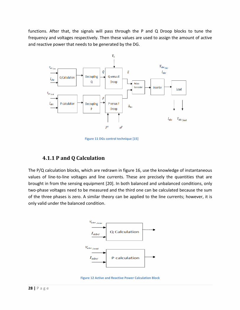
functions. After that, the signals will pass through the P and Q Droop blocks to tune the
frequency and voltages respectively. Then these values are used to assign the amount of active
and reactive power that needs to be generated by the DG.
Figure 11 DGs control technique [15]
4.1.1 P and Q Calculation
The P/Q calculation blocks, which are redrawn in figure 16, use the knowledge of instantaneous
values of line-to-line voltages and line currents. These are precisely the quantities that are
brought in from the sensing equipment [20]. In both balanced and unbalanced conditions, only
two-phase voltages need to be measured and the third one can be calculated because the sum
of the three phases is zero. A similar theory can be applied to the line currents; however, it is
only valid under the balanced condition.
Figure 12 Active and Reactive Power Calculation Block
29 | P a g e
The following equations are used to calculate the injected active and reactive powers into the
inverter [15]:
(4.1)
(4.2)
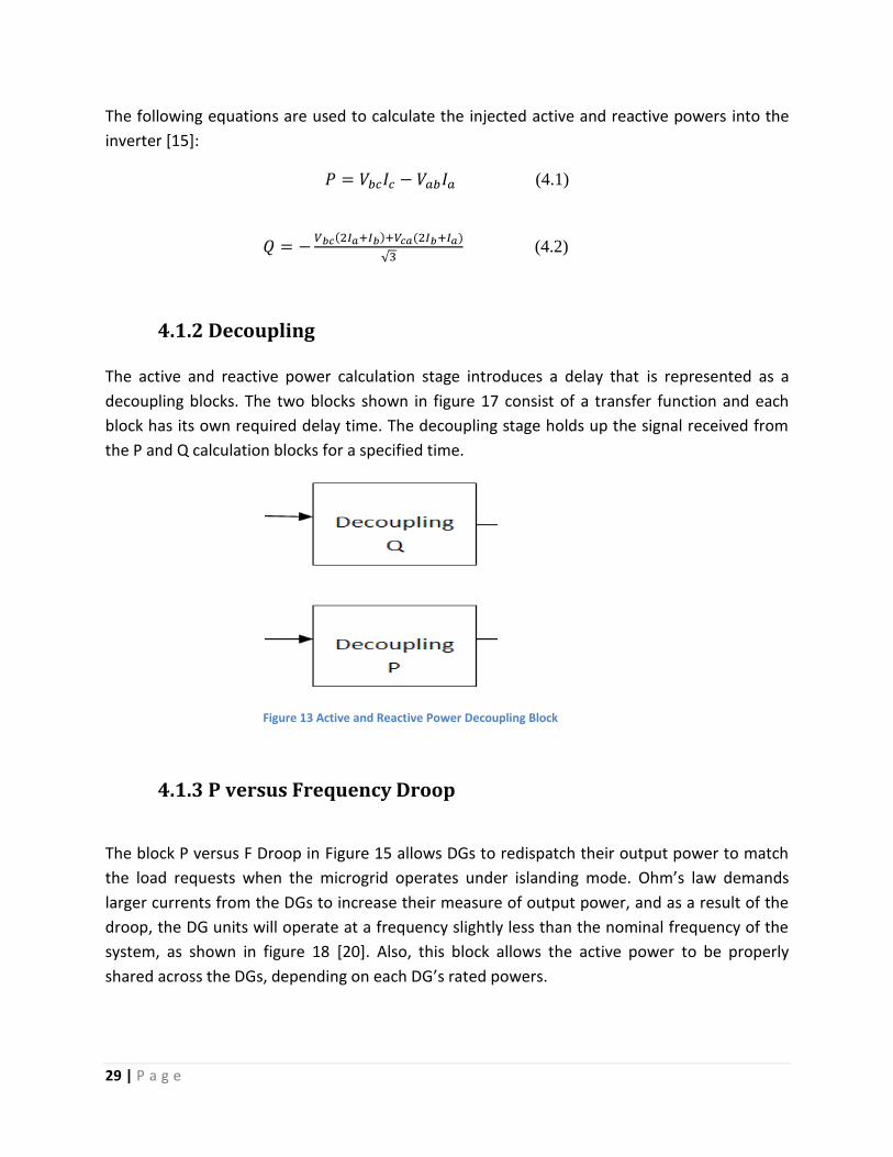
4.1.2 Decoupling
The active and reactive power calculation stage introduces a delay that is represented as a
decoupling blocks. The two blocks shown in figure 17 consist of a transfer function and each
block has its own required delay time. The decoupling stage holds up the signal received from
the P and Q calculation blocks for a specified time.
Figure 13 Active and Reactive Power Decoupling Block
4.1.3 P versus Frequency Droop
The block P versus F Droop in Figure 15 allows DGs to redispatch their output power to match
the load requests when the microgrid operates under islanding mode. Ohm’s law demands
larger currents from the DGs to increase their measure of output power, and as a result of the
droop, the DG units will operate at a frequency slightly less than the nominal frequency of the
system, as shown in figure 18 [20]. Also, this block allows the active power to be properly
shared across the DGs, depending on each DG’s rated powers.

30 | P a g e
Figure 14 Active Power Vs Frequency Droop Characteristic [20].
Figure 18 represents the characteristics of the active power vs. frequency droop for a system
that consist of two DGs. and are the setpoints for the active power in grid-connected
mode. However, when the microgrid disconnects from the utility grid, the frequency sags to a
new value, which in the graph is labelled as , and the two DGs will generate powers of
and respectively. In addition, since the two DGs have the same slope characteristics, this
will verify that each DG will share the total active power of the loads, dependent on each DG’s
rated power [15]. Clearly, the graph shows that the DGs increase their active power when the
frequency decreases. The following equations describe this relationship:
(4.3)
: = slope of the droop characteristics
= new angular frequency of the DG (when the microgrid switches to island mode) = angular frequency of the DG (when the microgrid is in grid-connected mode) = active power supplied by the DG (when the microgrid is in grid-connected mode) = real power supplied by the unit when the system is in island mode = frequency difference between grid-connected operation and the minimum allowable frequency.
= maximum active power available from the DG
The block diagram below shows the active power droop. Three inputs are injected in to the
control block: the measured and desired active power and the nominal microgrid frequency.
The output of this control block is the desired angle of the voltage at the inverter. This angle is
used to produce the gate pulses, which are fed into the generator.

31 | P a g e
Figure 15 Block Diagram of the Active Power Droop [20].
4.1.4 Q versus Voltage Droop
The reactive power versus voltage droop method is similar to the active power versus the
frequency droop method. This method is used in conventional power systems to assign a
specific voltage level at the output voltage sources that are calculated based on the injected
amount of reactive power. The main purpose of the voltage droop method is to regulate the
inverter with the appropriate voltage level. This method is an important element to ensure the
stability of the microgrid during disconnected operation because the voltages at each inverter
may vary for different technical reasons, which consequently may lead to an unstable system.
The block below shows the details of operation that occurred in the Q vs. E Droop block in
Figure 15.
Figure 16 Block Diagram of the Reactive Power Droop [20].
The inputs of the block diagram are the measured reactive power and the desired voltage
value, represented as Q and Ereq respectively. The output of this block is determined by the
linear characteristics of the droop, as shown in Figure 21. The new value of the desired voltage
that must be injected in the generator is Eo.
32 | P a g e
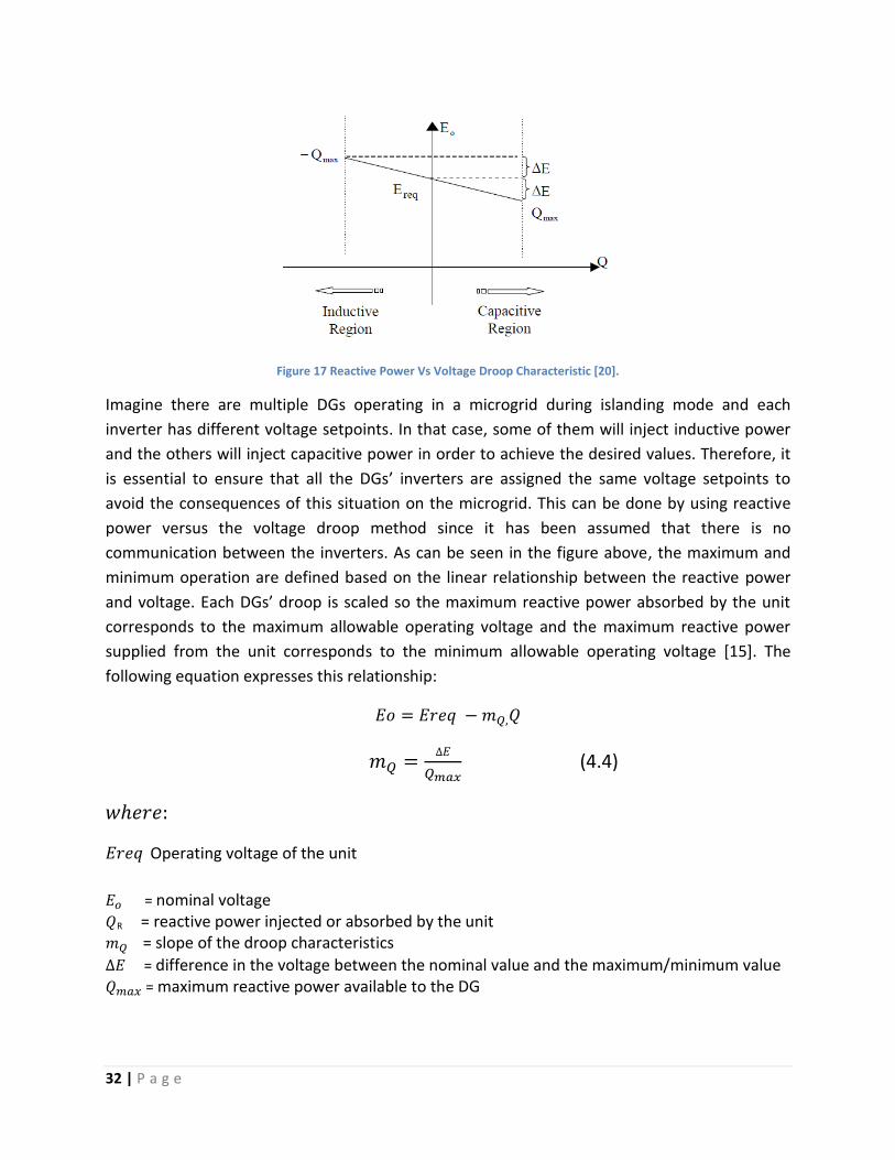
Figure 17 Reactive Power Vs Voltage Droop Characteristic [20].
Imagine there are multiple DGs operating in a microgrid during islanding mode and each
inverter has different voltage setpoints. In that case, some of them will inject inductive power
and the others will inject capacitive power in order to achieve the desired values. Therefore, it
is essential to ensure that all the DGs’ inverters are assigned the same voltage setpoints to
avoid the consequences of this situation on the microgrid. This can be done by using reactive
power versus the voltage droop method since it has been assumed that there is no
communication between the inverters. As can be seen in the figure above, the maximum and
minimum operation are defined based on the linear relationship between the reactive power
and voltage. Each DGs’ droop is scaled so the maximum reactive power absorbed by the unit
corresponds to the maximum allowable operating voltage and the maximum reactive power
supplied from the unit corresponds to the minimum allowable operating voltage [15]. The
following equation expresses this relationship:
(4.4)
Operating voltage of the unit
= nominal voltage
R = reactive power injected or absorbed by the unit
= slope of the droop characteristics
= difference in the voltage between the nominal value and the maximum/minimum value
= maximum reactive power available to the DG

33 | P a g e
From Equation 4.4 it can be seen that if a DG is absorbing reactive power (Q negative), then the
operating voltage will be higher than the nominal voltage, and if the DG is supplying reactive
power (Q positive), then the operating voltage will be smaller than the nominal voltage.

34 | P a g e
Chapter 5
5.0 Simulation Platform
5.1 Matlab Simulink
Matlab Simulink is a simulation software used for modelling, testing and analysing a dynamic
system. Simulink supports linear and nonlinear systems, which can be modelled in sampled or
continuous times. This software package provides a graphical interface, which makes the
program easy to use for the non-programming user. The Simulink library contains a range of
components that are used to design and test different types of electrical and mathematical
systems. The output of the simulated system can be represented as waveforms or numerical
data. More information about the use of Simulink can be found in [1].

35 | P a g e
5.2 Implementation of the Tested Microgrid
For the purpose of the thesis investigation and proposed control strategy, the LV microgrid
system shown in figure 22 has been designed and implemented in Simulink. The microgrid
system and scenario is adopted from [2] and will be discussed in Chapter 6.
Figure 18 Microgrid Design [8,10,13]
The main utility grid is represented by a 6.6kV distribution network model. The model consists
of a power plant, main grid load, distribution lines, interconnection switch and a transformer.
The implementation of these elements is described in the next section.
The distributed generator in the proposed system is a wind turbine and the loads are
represented as three-phase balanced loads. The generator is in three-phase Y-g configuration.
The operating voltage will be 240v with a tolerance of 5% and the system frequency will be

36 | P a g e
50Hz with a tolerance of 2%. Figure 23 shows the implemented design of the system in
Simulink.
Figure 19 Implementation of Microgrid Structure in Simulink

37 | P a g e
5.3 System Modeling
5.3.1 Utility Grid
The figure below represents the utility grid configuration in Simulink. A three-phase source has
been used as the utility plant connected to a distribution line, which ends at a static switch. The
static switch or PCC is represented as a three-phase breaker with a timer to assign a specific
time to disconnect the microgrid from the main utility grid. As can be seen from the figure, the
last block is the substation, which corresponds to a step-down transformer.
The PCC will isolate the microgrid when any disturbance occurs in the utility grid. However, in
this investigation, a specific time will be chosen to perform the disconnection because it is
impossible to implement a scenario where a fault occurs in the utility grid in Simulink.
Therefore, the Circuit Breaker Block is used as the PCC, which will give the user the control to
connect and disconnect the microgrid at any specific time.
The grid block shown in Figure 24 is a three-phase source, which has a configuration as the
swing generation type and the phase to phase RMS voltage is 6.6kV. The utility grid frequency is
50Hz and the transformer is 6.6/0.415kV. More details about the utility grid model are
mentioned in Appendix D.
Figure 20 Utility Grid Model
5.3.2 DG
As was stated in the beginning of this chapter, the system will consist of only one distributed
generator. The wind turbine is represented in Simulink as a simple voltage source to avoid the
complication of connecting a wind turbine model to the system. However, a wind turbine
model is designed in Appendix E to show the behaviour of the wind turbine in Simulink.

38 | P a g e
Figure 21 Distribution Generator
Figure 25 describes the DG that will be used in the system. The model consists of three
Controlled Voltage Source Blocks. These blocks will need an external controller to inject the
required amount of voltage that needs to be produced. The DG rated power is 40KVA. It has
been assumed that the DG is located near the loads; therefore, the effects of the lines’
impedance on the power received by the loads will be ignored. The droop controller method
that has been described in detail in Chapter 4 is used to provide the appropriate amount of
power that must be supplied to the system. More information about the controller design and
parameters can be found in Appendices B and C.
Figure 22 Implementation of Droop Control in Simulink
5.3.3 Load
A three-phase Series RLC Load Block (see figure 27) has been used as a load. Two of the
microgrid loads are considered as critical loads, which means that they must be supplied
continuously. The third load is non-critical, which will be disconnected from the microgrid
during island operation mode. To perform that function, a circuit breaker has been connected
to isolate and reconnect the non-critical load when the microgrid switches its operation mode.

39 | P a g e
Figure 23 Loads model

40 | P a g e
Chapter 6
6.0 Simulation Results and Discussion
6.1 Simulation scenario
The test scenario and load parameters are adopted from [2]. Basically, the main objective of
this test is to investigate the behaviour of the microgrid during disconnected mode. Also, this
test will verify the load-shedding technique, which is used to reduce the demand on DGs in
order to maintain the stability of the system.
As can be seen from Figure 23, the main grid is supplying its own load at a rated 27kw and the
microgrid is supplying three loads. The first two are critical loads, which must be supplied
continuously. The power ratings for the critical loads are 8.5kW and 12.5kW respectively. The
third one is a noncritical load, which will be eliminated when the microgrid disconnects from
the main grid. This load consumed 8.5kW, which means that the total microgrid load is 29.5kW.
The DG is rated at 40KVA. The DG controller design and configuration can be found in [15] and
Appendix B.
The microgrid will disconnect from the main grid after 0.5s from the simulation start. It has
been assumed that the DG is not able to supply the three loads at the same time without the
contribution of the utility grid. Therefore, load shedding will be performed on the non-critical
load when the microgrid is operating under island mode. The following figures show the results
for the main grid power, DG output power, system frequency, common bus voltage and the
demand by the loads.
41 | P a g e
6.2 Results Power Generation
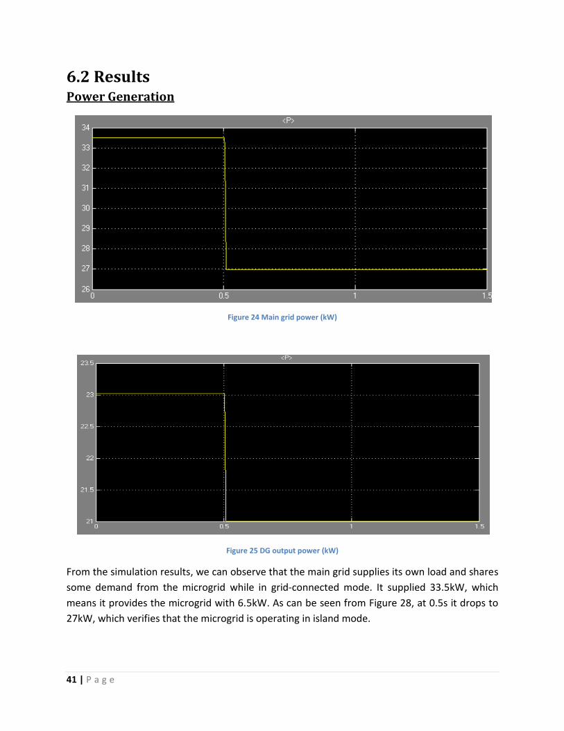
Figure 24 Main grid power (kW)
Figure 25 DG output power (kW)
From the simulation results, we can observe that the main grid supplies its own load and shares
some demand from the microgrid while in grid-connected mode. It supplied 33.5kW, which
means it provides the microgrid with 6.5kW. As can be seen from Figure 28, at 0.5s it drops to
27kW, which verifies that the microgrid is operating in island mode.

42 | P a g e
A similar situation with the DG output power is shown in Figure 29. According to the simulation
scenario, the non-critical load will be isolated during island operation, which means that the DG
will only need to supply the critical loads. Therefore, the DG generates about 23kw during the
connection of the main grid and when the operation switches to island mode, the output
generation drops to 21kw, which is equal to the sum of the critical loads demands.
System frequency and voltage
Figure 26 System frequency (Hz)
Figure 27 Common bus voltage (pu)
The system frequency during grid-connected mode is 51 Hz, which is within the acceptable
limits. However, this is not shown in Figure 30 because the system had not reached the steady
state. When the island mode operation starts, the DG inverter assumes the responsibility for

43 | P a g e
maintaining the frequency of the microgrid. The active power vs. the frequency droop method
mentioned in Chapter 4 will inject the nominal frequency, which will ensure that the power
produced by the DG is the required amount of power.
Moreover, the microgrid voltage in grid-connected mode was nearly 1pu. When the microgrid
operate in island mode the voltage drop to 0.97 pu, which confirm that the loads received
power with a suitable voltage level.
Microgrid critical loads demands
Figure 28 Critical Load 1 Power (W)
Figure 29 Critical Load 2 Power (W)
Moreover, the systems maintain the supply to the critical loads even when the utility power
cuts off, as shown in Figures 32 and 33. This confirms that the DG is able to provide the
necessary power during any unexpected events from the utility grid. The small oscillation on
the critical loads power at 0.5s and 1s is due to the snubber circuit in the switch block.

44 | P a g e
Microgrid non-critical load demand
Figure 30 Non-critical load power (W)
The non-critical load power is shown in Figure 34. As has been stated earlier, the non-critical
load will be isolated from the microgrid when the supply from the main grid stops because it
has been assumed that the DG is not able to supply all the loads at the same time. Therefore,
after performing the load shedding technique on the non-critical load, the power goes to zero
at 0.5s and it will return back to 8.5kw if the main grid supply resumes.

45 | P a g e
Chapter 7
7.0 Conclusion
This chapter summarises and outlines the main outcomes of this thesis, and also provides some
suggestions for future work.
7.1 Thesis conclusion
In conclusion, this thesis investigates the microgrid concept and proposes a control strategy
that can operate the microgrid during island operation mode in a proper and reliable way. The
first sections of the thesis introduce the microgrid concept and its main components. This
section also describes the microgrid operation and the main issues that need to be considered
under disconnected mode such as power quality, balance between supply and demands, and
voltage and frequency control. Also, protection concerns of the microgrid during both grid-
connected and island operation were stated. Moreover, a discussion on the microgrid control
operation such as types of control and DG control configuration are included as well. The first
few sections are very important and give an idea of the background of the thesis topic, which
will definitely help the reader to understand the analysis of the microgrid behaviour.
The control technique is the voltage source inverter control that is based on the P/Q Droop
control method. This method basically allows the DG to be self-controlled and does not require
any communication from other devices. Also the shedding of the non-critical load during island
operation was performed in order to maintain the power to the critical loads. The results
proved that the P/Q droop control method is able to provide the loads with the required power
and at the same time maintain the voltage and frequency within the acceptable limits.
7.2 Suggestion for future work
The main aim of this thesis is to investigate the behaviour of a microgrid during island operation
mode. However, it did not get involved in detail in the dynamic modelling. Rather, it just gives a
brief overview of the behaviour of a microgrid and proposes a method that can be employed in
order to control the system. There are many suggestions that can help to develop and extend
this thesis. For example, the secondary and tertiary control can be implemented in the system
to investigate the operation of each control type. Also, a full dynamic modelling of the DG can

46 | P a g e
be developed, such as verifying the behaviour of the prime movers and the inverters. Besides
that, storage devices can be modelled in the system to explore their impact on the microgrid
operation. Finally, different types of renewable energy can be use as the DG, for instance,
implementing the solar panel model and comparing its performance with the wind turbine
model.

47 | P a g e
8.0 References
1. Stanoyevitch, Alexander. 2005. Introduction to Matlab with Numerical Preliminaries Hoboken: Wiley-Interscience
2. Basak, Prasenjit , A. K. Saha, S. Chowdhury, and S. P. Chowdhury. 2009. Microgrid:
Control Techniques and Modeling. Universities Power Engineering Conference (UPEC), 2009 Proceedings of the 44th International:1-5.
3. Vechiu. I, C. Octavian, A. Llaria, and H. Camblong. Control of Power Converters for Microgrids. University of the Basque Country, Spain. www.emeraldinsight.com/0332-1649.htm, accessed on 17/11/2012
4. Iqbal, Atif, A. Lamine, I. Ashra, and M. Shaleh,.2006. Matlab/Simulink Model of Space Vector PWM for Three-Phase Voltage Source Inverter. Universities Power Engineering Conference, UPEC '06. Proceedings of the 41st International (2006): 1096-1100.
5. Bogdan, S. Borowy and Ziyad M. Salameh. 1997. Dynamic Response of a Stand-Alone Wind Energy Conversion System with Battery Energy Storage to a Wind Gust. IEEE Transactions on Energy Conversion, Vol. 12, No. 1, March 1997
6. Reshadat, A. S,Hussain. K, Shahab. 2010. Introduction of Microgrid. www.scribd.com accessed on 9/11/2012
7. Chowdhury, Sunetra, Crossley, Peter & Chowdhury, S. P. 2009. Microgrids and active distribution networks. London: Institution of Engineering and Technology.
8. Direct Industry. 2012. The Virtual Industrial Exhibition. http://www.directindustry.com, accessed on 17/11/2012
9. Todd, J. M. Straten, M. Schaefer, and J. Yowell, 2012. Wind Energy. TEACH Engineering. http://www.teachengineering.org/view_activity.php?url=collection/cub_/activities/cub_earth/cub_earth_lesson04_activity2.xml, accessed on 03/11/2012
10. Madison, N. 2012. What is Solar Power?.Wise Geek. http://www.wisegeek.org/what-is-solar-power.htm, accessed on 13/11/2012
11. Wekhande, S & A. Vivek. 1999. A Variable Speed Constant Voltage Controller For Self-
Excited Induction Generator With Minimum Control Requirements. Indian Institute of Technology-Bombay, India.

48 | P a g e
12. Vasquez, Juan, Guerrero, Josep, Miret, Jaume, Castilla, Miguel & Vicuna, Luis Garcia de. 2010. Hierarchical control of intelligent microgrids. IEEE Industrial Electronics Magazine 4(4), 7.
13. Hangzhou Hydrotu Engineering co.,ltd. 2012. http://www.hydrotu.com/synchronous_hydroelectric_generator-294036.html, accessed on 10/11/2012
14. Pecas. J. 2006. Defining Control Strategies for Microgrids Islanded Operation. IEEE Power & Energy Magazine.
15. Mohammad, A. 2010. Microgrid: Modelling and Control. Perth: Murdoch University.
16. Quintero, J. Vasquez. 2009. Decentralized control techniques applied to electric power distributed generation in microgrids. PhD, Universitat Politècnica de Catalunya.
17. Nikkhajoei. H. 2007. Microgrid Protection. IEEE Power & Energy Magazine.
18. Johan. D, V. Pieter, B. Ronnie. 2003. Protection Issues in Microgrids with Multiple Distributed Generation Units. Belgium. http://www.esat.kuleuven.be/electa, accessed on 15/11/2012
19. Seon-Ju. A, P.Jin-Woo, M. Seung-Il, and N. Sang-Ryul. 2010. Power-Sharing Method of Multiple Distributed Generators Considering Control Modes and Configrurations of a Microgrid.IEEE Transaction on Power Delivery, Vol. 25, No. 3, July 2010
20. Robert H. Lasseter and Paolo Piagi. 2006. Control and Design of Microgrid Components. University of Wisconsin-Madison.
21. Alsharekh. H. 2011. Microgrid: Potential function based on secondary control of the
microgrid. Perth: Murdoch University.
22. A.P. Lopes, C.L. Moreira, and F.O. Resende. 2005. Microgrids black start and islanded operation. http://www.montefiore.ulg.ac.be/services/stochastic/pscc05/papers/fp69.pdf, accessed on 12/11/2012

49 | P a g e
9.0 Appendices
9.1 Appendix A (System Parameter)
Cable inductance and resistance:
DG: The DG cable inductance and resistance can be calculated by using the following equation:
The inductance and resistance values chosen to be 0.1pu, therefore the inductance and
resistance of the cable of each Controlled Voltage Source Block is:

50 | P a g e
9.2 Appendix B (DG Controller Design) DG Controller Parameter
Rated power = 40 kVA
Constant time of active power decoupling = 0.1s
Constant time of reactive power decoupling = 0.2s
mP =
mQ=
0 = rad/s
V0 = 240V
DG Controller Implementation
Figure 31 VSI three phase control model [22]
The figure above describes the voltage source inverter three phase control based on P/Q droop
method that used in this thesis. This system has been implemented in Simulink as shown in
figure 36. The only change performed in the implementation is the removal of the kff loop. This
loop corresponds to a phase feed-forward control, which can improve the stability in the
controller. However, this removal did not have a big impact on the controller behavior and
stability.

51 | P a g e
Figure 32 Implementation of Droop Control in Simulink
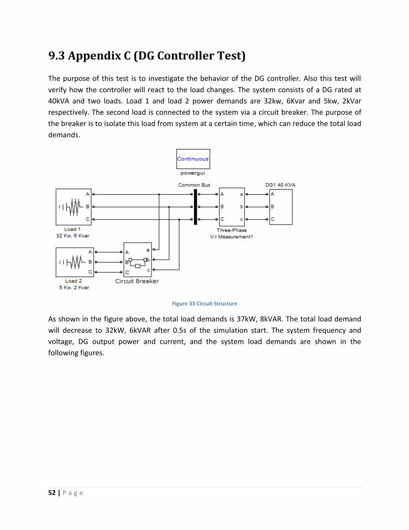
52 | P a g e
9.3 Appendix C (DG Controller Test)
The purpose of this test is to investigate the behavior of the DG controller. Also this test will
verify how the controller will react to the load changes. The system consists of a DG rated at
40kVA and two loads. Load 1 and load 2 power demands are 32kw, 6Kvar and 5kw, 2kVar
respectively. The second load is connected to the system via a circuit breaker. The purpose of
the breaker is to isolate this load from system at a certain time, which can reduce the total load
demands.
Figure 33 Circuit Structure
As shown in the figure above, the total load demands is 37kW, 8kVAR. The total load demand
will decrease to 32kW, 6kVAR after 0.5s of the simulation start. The system frequency and
voltage, DG output power and current, and the system load demands are shown in the
following figures.

53 | P a g e
Results:-
1- System frequency and voltage
Figure 34 System frequency (Hz)
Figure 35 Common Bus Voltage (pu)
As it seen from figure 38 that the system frequency was increasing rapidly till 0.5s where the
total load been reduced. Obviously, the load variation had a noticeable impact on the
frequency. At the beginning of the simulation the total active power of the load was almost
equal to the maximum active power that the DG can produce, however when the total system
loads been reduced the frequency stabilize at 50.5Hz which is within the acceptable limits. In
contrast, the voltage level of the system was around 0.96pu and then it settled at 0.976pu
when the total reactive power reduced to 6kvar as shown in figure 39.

54 | P a g e
2- Power Generation
Figure 36 DG1 Active (yellow) and Reactive (purple) Powers (W)
Figure 37 Loads Active (yellow) and Reactive (purple) Powers (W)
Obviously the DG controller perfectly supplied the load with the required power need as shown
in the figures above. Besides DG decreased its output powers when the total load demands of
the system has decreased. The yellow and the purple lines correspond to the active and
reactive power respectively.

55 | P a g e
9.4 Appendix D (Utility Grid)
The figure below represents the utility grid configuration in Simulink. A three phase source has
been used as the utility plant connected to a distribution lines, which ends at a static switch.
The static switch or PCC are represented as a three phase breaker with a timer to assign a
specific time for disconnects the microgrid from the main utility grid. As it can be seen from the
figure, the last block is the substation, which is corresponded to a Step-down transformer.
Figure 38 Utility Grid model
Utility Grid model parameter: Three Phase Source: Generator Type – Swing Phase to Phase rms voltage – 6.6Kv Frequency – 50Hz Distribution Lines: Resistance per unit length (Ohms/Km) – [0.01273 0.3864] Line length – 100Km Transformer: Winding 1 – 6600Vrms Winding2 – 415Vrms
Figure 39 Substation Voltage (v)

56 | P a g e
9.5 Appendix E (Wind Turbine)
The figure below represents the wind turbine model in Simulink. The reason of not using this
model in the thesis test was because it very complicated to connect it with a P/Q droop method
controller. The wind turbine model configuration is taken from [5, 15]. The output power of the
wind turbine represented in figure 37 is 1.9339 KW. The aim of this test is implement a
complete model of a wind turbine in Simulink, which can assist and help any future work on this
thesis.
Figure 40 Wind Turbine model in Simulink
. Figure 41 Wind Turbine output power (W)