Embed Size (px)
Citation preview

FACT
ORY
AUTO
MAT
ION
Manual
IVI-KHD2-4HD1Control Unit

With regard to the supply of products, the current issue of the following document is applicable:The General Terms of Delivery for Products and Services of the Electrical Industry, as published by
the Central Association of the “Elektrotechnik und Elektroindustrie (ZVEI) e.V.v“, including the supplementary clause “Extended reservation of title“.
We at Pepperl+Fuchs recognise a duty to make a contribution to the future.For this reason, this printed matter is produced on paper bleached without the use of chlorine.
1Subject to reasonable modifications due to technical advances. Copyright Pepperl+Fuchs, Printed in Germany
Pepperl+Fuchs Group · Tel.: (6 21) 7 76-11 11 · USA (3 30) 4 25 35 55 · Singapore 7 79 90 91 · Internet http://www.pepperl-fuchs.com
Dat
e of
Issu
e 28
.06.
2000
Control Unit with 16 Inputs/OutputsIVI-KHD2-4HD1
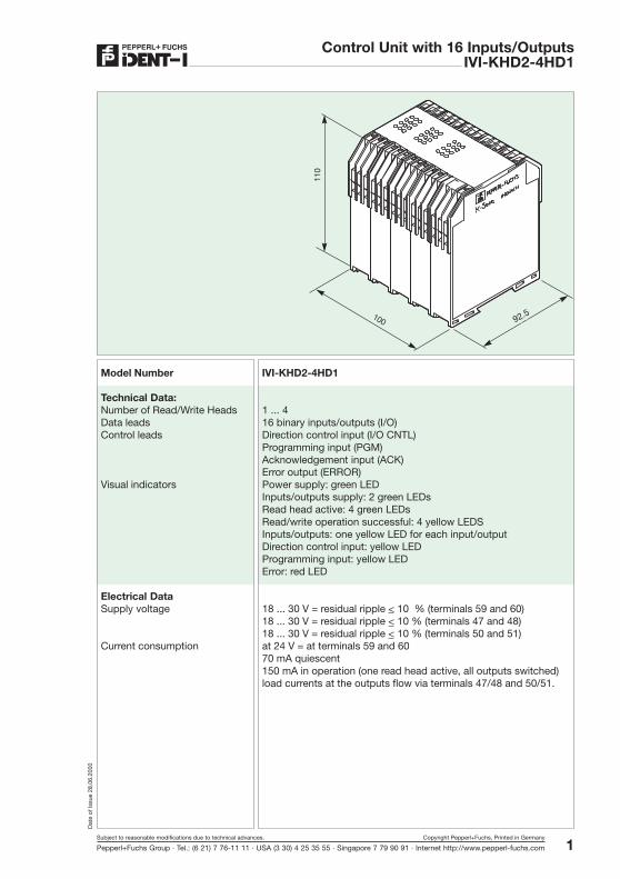
Model Number IVI-KHD2-4HD1
Technical Data:Number of Read/Write Heads 1 ... 4Data leads 16 binary inputs/outputs (I/O)Control leads Direction control input (I/O CNTL)
Programming input (PGM)Acknowledgement input (ACK)Error output (ERROR)
Visual indicators Power supply: green LEDInputs/outputs supply: 2 green LEDsRead head active: 4 green LEDsRead/write operation successful: 4 yellow LEDSInputs/outputs: one yellow LED for each input/outputDirection control input: yellow LEDProgramming input: yellow LEDError: red LED
Electrical DataSupply voltage 18 ... 30 V = residual ripple < 10 % (terminals 59 and 60)
18 ... 30 V = residual ripple < 10 % (terminals 47 and 48)18 ... 30 V = residual ripple < 10 % (terminals 50 and 51)
Current consumption at 24 V = at terminals 59 and 6070 mA quiescent150 mA in operation (one read head active, all outputs switched)load currents at the outputs flow via terminals 47/48 and 50/51.
92.5

Control Unit with 16 Inputs/OutputsIVI-KHD2-4HD1
2Subject to reasonable modifications due to technical advances. Copyright Pepperl+Fuchs, Printed in Germany
Pepperl+Fuchs Group · Tel.: (6 21) 7 76-11 11 · USA (3 30) 4 25 35 55 · Singapore 7 79 90 91 · Internet http://www.pepperl-fuchs.com
Dat
e of
Issu
e 28
.06.
2000
Inputs and Outputs Input voltage 0 ... 7 V corresponds to logic 0Input voltage 13 ... 30 V corresponds to logic 1
Output voltage Data outputs: min. supply voltage -0.5 VControl outputs: min. supply voltage -1.0 VPositive switching outputs; i.e. for logic 0 the output potential isindeterminate.Short circuit proof, all outputs switch off if overloaded
Output current Average 600 mA per group of 4 outputsMax. 600 mA per group of 4 outputsGroups: 1/2/3/16, 17/18/31/32, 4/5/6/19, 20/21/34/35Control outputs current: max. 20 mAData and control inputs resistance: typically 74 kOhm
Environmental conditionsOperating temperature 248 Kelvin ... 343 Kelvin (-25 °C ... +70 °C)Storage temperature 248 Kelvin ... 358 Kelvin (-25 °C ... +85 °C)Moisture max. 75 % relative humidity
Protection class per DIN 40050 IP20
Mechanical:Construction 100 mm wide terminal housingMounting By snapping on to DIN 46277 rail or by screws through extendable
tabs (per DIN 43602)Housing material Makrolon 6485Flammability class UL94Electrical connection Self-opening instrument terminals, max. conductor csa 2 x 2.5mm2
Control Unit IVI-KHD2-4HD1
3Subject to reasonable modifications due to technical advances. Copyright Pepperl+Fuchs, Printed in Germany
Pepperl+Fuchs Group · Tel.: (6 21) 7 76-11 11 · USA (3 30) 4 25 35 55 · Singapore 7 79 90 91 · Internet http://www.pepperl-fuchs.com
Dat
e of
Issu
e 28
.06.
2000
Control Unit with 16 Inputs/OutputsIVI-KHD2-4HD1
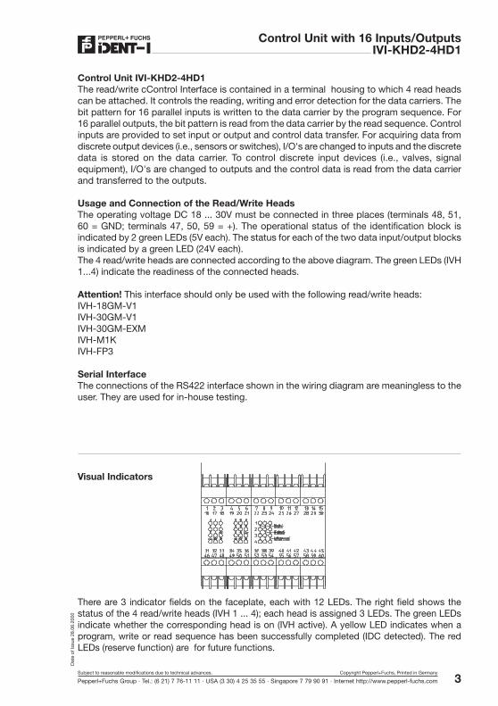
Visual Indicators
There are 3 indicator fields on the faceplate, each with 12 LEDs. The right field shows thestatus of the 4 read/write heads (IVH 1 ... 4); each head is assigned 3 LEDs. The green LEDsindicate whether the corresponding head is on (IVH active). A yellow LED indicates when aprogram, write or read sequence has been successfully completed (IDC detected). The redLEDs (reserve function) are for future functions.
Control Unit IVI-KHD2-4HD1The read/write cControl Interface is contained in a terminal housing to which 4 read headscan be attached. It controls the reading, writing and error detection for the data carriers. Thebit pattern for 16 parallel inputs is written to the data carrier by the program sequence. For16 parallel outputs, the bit pattern is read from the data carrier by the read sequence. Controlinputs are provided to set input or output and control data transfer. For acquiring data fromdiscrete output devices (i.e., sensors or switches), I/O's are changed to inputs and the discretedata is stored on the data carrier. To control discrete input devices (i.e., valves, signalequipment), I/O's are changed to outputs and the control data is read from the data carrierand transferred to the outputs.
Usage and Connection of the Read/Write HeadsThe operating voltage DC 18 ... 30V must be connected in three places (terminals 48, 51,60 = GND; terminals 47, 50, 59 = +). The operational status of the identification block isindicated by 2 green LEDs (5V each). The status for each of the two data input/output blocksis indicated by a green LED (24V each).The 4 read/write heads are connected according to the above diagram. The green LEDs (IVH1...4) indicate the readiness of the connected heads.
Attention! This interface should only be used with the following read/write heads:IVH-18GM-V1IVH-30GM-V1IVH-30GM-EXMIVH-M1KIVH-FP3
Serial InterfaceThe connections of the RS422 interface shown in the wiring diagram are meaningless to theuser. They are used for in-house testing.
Control Unit with 16 Inputs/OutputsIVI-KHD2-4HD1
4Subject to reasonable modifications due to technical advances. Copyright Pepperl+Fuchs, Printed in Germany
Pepperl+Fuchs Group · Tel.: (6 21) 7 76-11 11 · USA (3 30) 4 25 35 55 · Singapore 7 79 90 91 · Internet http://www.pepperl-fuchs.com
Dat
e of
Issu
e 28
.06.
2000
The left and middle indicator fields show the status of both input/output blocks:The yellow LEDs (1 ... 16) signal a high level on the respective data input/output lines.The two green LEDs (5 V) and (24 V) indicate the status of the identification block and theinput/output end levels.4 LEDs display the high levels of the control lines in the middle field:Yellow, (PGM) programming input.Yellow, (ACK) acknowledgement input.Yellow, (I/O CNTL) direction control input (high = input/data carrier programming)Red, (ERROR) error output.
Programming/Writing to a Data Carrier
The 16 binary inputs/outputs are switched to inputs. The bit pattern (information from sensors,switches or the outputs of plc) is accepted by the control interface unit through these 16inputs in order to program the data carrier. The control interface unit makes a programattempt at the first connected read/write head. If a data carrier is recognized and successfullyprogrammed, the program sequence is terminated. Otherwise the programming attemptcontinues with the next read/write head until successful. If all attempts are unsuccessful,then the error output is set.
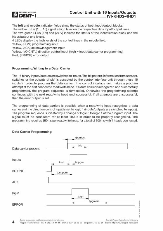
The programming of data carriers is possible when a read/write head recognizes a datacarrier and the direction control input is set to logic 1 (inputs/outputs are switched to inputs).The program sequence is initiated by a change of logic 0 to logic 1 at the program input. Thesignal must be consistent for at least 100ms in order to be properly recognized. Theprogramming requires 150ms per read/write head, for a total of 600ms with 4 heads connected.
Data Carrier Programming:
tpgmerr
tpgm
tcntlpgm
tcntl tiopgm
thio
tpgmdc
Data carrier present
Inputs
I/O CNTL
ACK
PGM
ERROR
5Subject to reasonable modifications due to technical advances. Copyright Pepperl+Fuchs, Printed in Germany
Pepperl+Fuchs Group · Tel.: (6 21) 7 76-11 11 · USA (3 30) 4 25 35 55 · Singapore 7 79 90 91 · Internet http://www.pepperl-fuchs.com
Dat
e of
Issu
e 28
.06.
2000
Control Unit with 16 Inputs/OutputsIVI-KHD2-4HD1
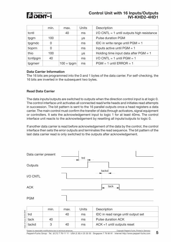
min. max. Units Description
tcntl 40 ms I/O CNTL = 1 until outputs high resistance
tpgm 100 µs Pulse duration PGM
tpgmdc 0 ms IDC in write range until PGM = 1
tioprm 0 ms Inputs active until PGM = 1
thio 100 µs Holding time input data after PGM = 1
tcntlpgm 40 ms I/O CNTL = 1 until PGM = 1
tpgmerr 100 + tpgm ms PGM = 1 until ERROR = 1
Data Carrier InformationThe 16 bits are programmed into the 0 and 1 bytes of the data carrier. For self-checking, the16 bits are inverted in the subsequent two bytes.
Read Data Carrier
The data inputs/outputs are switched to outputs when the direction control input is at logic 0.The control interface unit activates all connected read/write heads and initiates read attemptsin succession. The bit pattern is sent to the 16 parallel outputs once a head registers a datacarrier. The main control must confirm the transfer of data through activators, signal equipmentor controllers. It sets the acknowledgement input to logic 1 for at least 40ms. The controlinterface unit reacts to the acknowledgement by resetting all inputs/outputs to logic 0.
If another data carrier is read before acknowledgement of the data by the control, the controlinterface then sets the error outputs and terminates the read sequence. The bit pattern of thelast data carrier read is only switched to the outputs after acknowledgement.
min. max. Units Description
trd 40 ms IDC in read range until output set
tack 40 ms Pulse duration ACK
tackd 3 40 ms ACK =1 until outputs reset
Data carrier present
Outputs
I/O CNTL
ACK
PGM
trd
tack
tackd
Control Unit with 16 Inputs/OutputsIVI-KHD2-4HD1
6Subject to reasonable modifications due to technical advances. Copyright Pepperl+Fuchs, Printed in Germany
Pepperl+Fuchs Group · Tel.: (6 21) 7 76-11 11 · USA (3 30) 4 25 35 55 · Singapore 7 79 90 91 · Internet http://www.pepperl-fuchs.com
Dat
e of
Issu
e 28
.06.
2000
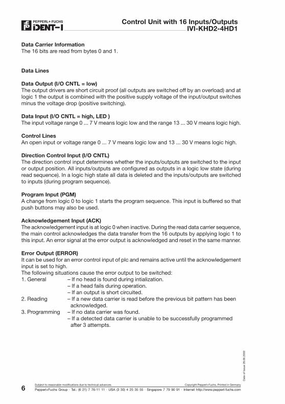
Data Carrier InformationThe 16 bits are read from bytes 0 and 1.
Data Lines
Data Output (I/O CNTL = low)The output drivers are short circuit proof (all outputs are switched off by an overload) and atlogic 1 the output is combined with the positive supply voltage of the input/output switchesminus the voltage drop (positive switching).
Data Input (I/O CNTL = high, LED )The input voltage range 0 ... 7 V means logic low and the range 13 ... 30 V means logic high.
Control LinesAn open input or voltage range 0 ... 7 V means logic low and 13 ... 30 V means logic high.
Direction Control Input (I/O CNTL)The direction control input determines whether the inputs/outputs are switched to the inputor output position. All inputs/outputs are configured as outputs in a logic low state (duringread sequence). In a logic high state all data is deleted and the inputs/outputs are switchedto inputs (during program sequence).
Program Input (PGM)A change from logic 0 to logic 1 starts the program sequence. This input is buffered so thatpush buttons may also be used.
Acknowledgement Input (ACK)The acknowledgement input is at logic 0 when inactive. During the read data carrier sequence,the main control acknowledges the data transfer from the 16 outputs by applying logic 1 tothis input. An error signal at the error output is acknowledged and reset in the same manner.
Error Output (ERROR)It can be used for an error control input of plc and remains active until the acknowledgementinput is set to high.The following situations cause the error output to be switched:1. General – If no head is found during intialization.
– If a head fails during operation.– If an output is short circuited.
2. Reading – If a new data carrier is read before the previous bit pattern has been acknowledged.
3. Programming – If no data carrier was found.– If a detected data carrier is unable to be successfully programmed after 3 attempts.

With regard to the supply of products, the current issue of the following document is applicable:The General Terms of Delivery for Products and Services of the Electrical Industry, as published by
the Central Association of the “Elektrotechnik und Elektroindustrie (ZVEI) e.V.v“, including the supplementary clause “Extended reservation of title“.
We at Pepperl+Fuchs recognise a duty to make a contribution to the future.For this reason, this printed matter is produced on paper bleached without the use of chlorine.
One Company, Two Divisions.Process Automation
Division
Factory Automation
Division
Product Range
Signal conditioners
Intrinsically safe interface modules
Remote Process Interface (RPI)
Intrinsically safe field bus solutions
Level control sensors
Process measuring and control systems
engineering at the interface level
Intrinsic safety training
Areas of Application
Chemical industry
Industrial and community sewage
Oil, gas and petrochemical industry
PLC and process control systems
Engineering companies for process systems
Product Range
Digital and analogue sensors
in different technologies
Inductive and capacitive sensors
Magnetic sensors
Ultrasonic sensors
Photoelectric sensors
Incremental and absolute rotary encoders
Counters and control equipment
Identification Systems
AS-Interface
Areas of Application
Machine engineering
Conveyor or transport
Packaging and bottling
Automotive industry
Subject to reasonable modifications due to technical advances � Copyright PEPPERL+FUCHS � Printed in Germany � Part. No.
Worldwide Headquarters
Pepperl+Fuchs GmbH � Königsberger Allee 87
68307 Mannheim � Germany
Tel. +49 621 7 76-0 � Fax +49 621 7 76-10 00
http://www.pepperl-fuchs.com
e-mail: [email protected]
The Pepperl+Fuchs Group
USA Headquarters
Pepperl+Fuchs Inc. � 1600 Enterprise Parkway
Twinsburg, Ohio 44087 � Cleveland-USA
Tel. (330) 4 25 35 55 � Fax (330) 4 25 46 07
e-mail: [email protected]
Asia Pacific Headquarters
Pepperl+Fuchs Pte Ltd. � P+F Building
18 Ayer Rajah Crescent � Singapore 139942
Tel. (65) 7 79 90 91 � Fax (65) 8 73 16 37
e-mail: [email protected]
Service Area
Worldwide sales, customer service and consultation via competent and reliable Pepperl+Fuchs
associates ensure that you can contact us wherever or whenever you need us. We have
subsidiaries worldwide for your convenience.
41 852 01/97 02