Embed Size (px)
Citation preview
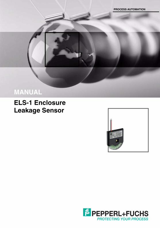
ELS-1 Enclosure Leakage Sensor
PROCESS AUTOMATION
MANUAL

With regard to the supply of products, the current issue of the following document is applicable: The General Terms of Delivery for Products and Services of the Electrical Industry, published by the
Central Association of the Electrical Industry (Zentralverband Elektrotechnik und Elektroindustrie (ZVEI) e.V.) in its most recent version as well as the supplementary clause: "Expanded reservation
of proprietorship"
ELS-1 Enclosure Leakage Sensor

ELS-1 Enclosure Leakage SensorContents
2012
-10
3
1 Safety................................................................................... 41.1 Validity ..........................................................................................................41.2 Symbols used ...............................................................................................41.3 System Operator and Personnel ...................................................................41.4 Pertinent Laws, Standards, Directives, and further Documentation ...............51.5 Marking.........................................................................................................51.6 Intended Use ................................................................................................51.7 Mounting and Installation ..............................................................................6
1.7.1 Intrinsically Safe Circuits...........................................................................61.7.2 Ex nA........................................................................................................6
1.8 Repair and Maintenance...............................................................................61.9 Delivery, Transport and Storage ....................................................................71.10 Disposal ........................................................................................................7
2 Product Specifications....................................................... 82.1 Overview and Application .............................................................................82.2 Component Identity.......................................................................................9
2.2.1 Technical Data..........................................................................................92.2.2 Dimensional Drawing .............................................................................10
3 Installation......................................................................... 113.1 Installation of ELS-1 ....................................................................................11
4 Commissioning................................................................. 124.1 Compatibility ...............................................................................................124.2 Segment Design .........................................................................................12
5 Troubleshooting................................................................ 135.1 Sensor Alarm ..............................................................................................135.2 Status and Error Messages .........................................................................13
ELS-1 Enclosure Leakage Sensor

ELS-1 Enclosure Leakage SensorSafety
ELS-1 Enclosure Leakage Sensor
2012
-10
1 Safety1.1 Validity
The chapter “Safety” is valid as instruction manual.Specific processes and instructions in this document require special precautions to guarantee the safety of the operating personnel.
1.2 Symbols usedThis document contains information that you must read for your own personal safety and to avoid property damage. Depending on the hazard category, the warning signs are displayed in descending order as follows:Safety-relevant symbols
Informative symbols
ActionThis symbol indicates a paragraph with instructions.
1.3 System Operator and PersonnelThe plant owner is responsible for its planning, installation, commissioning, operation, maintenance and disassembly.Mounting, installation, commissioning, operation, maintenance and disassembly of any devices may only be carried out by trained, qualified personnel. The instruction manual must be read and understood.
Danger!This symbol indicates a warning about an immediate possible danger.In case of ignoring the consequences may range from personal injury to death.
Warning!This symbol indicates a warning about a possible fault or danger.In case of ignoring the consequences may cause personal injury or heaviest property damage.
Caution!This symbol indicates a warning about a possible fault.In case of ignoring the devices and any connected facilities or systems may be interrupted or fail completely.
Note!This symbol brings important information to your attention.
4

ELS-1 Enclosure Leakage SensorSafety
2012
-10
1.4 Pertinent Laws, Standards, Directives, and further DocumentationLaws, standards, or directives applicable to the intended use must be observed. In relation to hazardous areas, Directive 1999/92/EC must be observed.The corresponding data sheets, declarations of conformity, EC Type-examination certificates, certificates and Control Drawings if applicable (see data sheet) are an integral part of this document. You can find this information under www.pepperl-fuchs.com.Due to constant revisions, documentation is subject to permanent change. Please refer only to the most up-to-date version, which can be found under www.pepperl-fuchs.com.
1.5 MarkingThe ELS-1 is marked with:
Electrical data see EC-type-examination certificate or datasheet.1.6 Intended Use
The ELS-1 is used as an early warning system designed to detect water ingress within field device housings or junction boxes before the water breach can lead to communication failure, excessive segment current or irreversible terminal or cable galvanic corrosion.The ELS-1 is designed to be used in conjunction with Pepperl+Fuchs Fieldbus Power Hubs, fieldbus couplers and field devices as part of the advanced physical layer diagnostic infrastructure for IEC 61158-2 FOUNDATION fieldbus and PROFIBUS PA IEC 61158-2 systems.The device is designed for use in intrinsically safe fieldbus systems according to FISCO or Entity.The devices are only approved for appropriate and intended use. Ignoring these instructions will void any warranty and absolve the manufacturer from any liability.The device must only be operated in the ambient temperature range specified.
Pepperl+Fuchs GmbHLilienthalstrasse 200, 68307 Mannheim, GermanyELS-1SIRA 12 ATEX 2129X
II 1G Ex ia IIC T4SIRA 12 ATEX 4154X
II 3G Ex nAc IIC T4 , II 3G Ex ic IIC T4
5
ELS-1 Enclosure Leakage SensorSafety
2012
-10
1.7 Mounting and InstallationThe installation instructions in accordance with IEC/EN 60079-14 must be observed.Prior to mounting, installation, and commissioning of the device you should make yourself familiar with the device and carefully read the instruction manual.Avoid electrostatic discharges while operating the installed device. Avoid electrostatic charge.If devices have already been operated in general electrical systems, they may subsequently no longer be installed in electrical systems used in combination with hazardous areas.If "Ex i" protected circuits (intrinsically safe) are operated with non-intrinsically safe circuits, they must no longer be used as "Ex i" protected circuits.The maximum cable length is 1 m.
1.7.1 Intrinsically Safe CircuitsThe protective sleeve provided with the equipment must be installed in accordance with the instruction.Avoid electrostatic discharges while operating the installed device. Avoid electrostatic charge.
1.7.2 Ex nAThe devices must be installed and operated only in enclosures that
■ comply with the requirements for enclosures according to IEC/EN 60079-0■ are rated with the degree of protection IP54 according to IEC/EN 60529
Provision must be made on installation, to provide transient protection to the device not exceeding 140 % of the peak value of rated voltage.The connection lines must be installed such that the type of protection "nAc" is maintained.
1.8 Repair and MaintenanceThe devices must not be repaired, changed or manipulated. If there is a defect, the product must always be replaced with an original device.
6

ELS-1 Enclosure Leakage SensorSafety
2012
-10
1.9 Delivery, Transport and StorageCheck the packaging and contents for damage. Check if you have received every item and if the items received are the ones you ordered.Keep the original packaging. Always store and transport the device in the original packaging.Always store the device in a clean and dry environment. The permitted storage temperature (see data sheet) must be considered.
1.10 DisposalDisposing of devices, packaging material, and possibly contained batteries must be in compliance with the applicable laws and guidelines of the respective country.
7

ELS-1 Enclosure Leakage SensorProduct Specifications
ELS-1 Enclosure Leakage Sensor
2012
-10
2 Product Specifications2.1 Overview and Application
The FieldConnex® early warning Enclosure Leakage Sensor ELS-1 contains a unique diagnostic function to detect water ingress breaches within field device housings or junction boxes before it can adversely affect fieldbus communication, demand high current levels or even lead to irreversible galvanic corrosion damage to electronics, terminals or cable parts. Its compact design allows the ELS-1 to fit into most of today’s existing field device housings.The sensor is designed for use in fieldbus communication topologies according to IEC 61158-2 as FOUNDATION Fieldbus and PROFIBUS PA. The ELS-1 is conforming to IEC 60079-11 intrinsically safe FISCO and Entity concepts as associated apparatus allowing them to be attached to any fieldbus trunk or spur that is intrinsically safe certified.The ELS-1 can be connected in parallel to the spur output cables of Pepperl+Fuchs fieldbus couplers type R2-SP-IC*, F2-SP-IC* and R4D0-FB-* and powered from the spur, requiring less than 6 mA for operation.Once water is detected, the diagnostic electronics generates an alarm that the Pepperl+Fuchs Advanced Diagnostics infrastructure receives, whereon this alarm will be transmitted to the system’s maintenance or operator station containing Pepperl+Fuchs Diagnostic Manager software. The Diagnostic Manager software shows sensor alarms as a “Coupler alarm” by tagging field devices connected to the same spur as the ELS-1, thus enabling the maintenance engineer to easily identify the affected enclosure. Additionally, the ELS-1 provides a visual alarm that helps to quickly identify the affected device or housing, or to validate the fault.
8
ELS-1 Enclosure Leakage SensorProduct Specifications
2012
-10
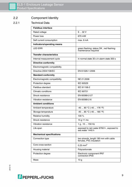
2.2 Component Identity2.2.1 Technical Data
Fieldbus interfaceRated voltage 9 ... 32 VPower loss 670 mWSelf current consumption max. 6 mAIndicators/operating meansLED ERR green flashing: status OK , red flashing:
maintenance requiredTransfer characteristicsInternal measurement cycle in normal state 30 s in alarm state 300 sDirective conformityElectromagnetic compatibilityDirective 2004/108/EC EN 61326-1:2006Standard conformityElectromagnetic compatibility NE 21:2006Protection degree IEC 60529Fieldbus standard IEC 61158-2Climatic conditions IEC 60721Shock resistance EN 60068-2-27Vibration resistance EN 60068-2-6Ambient conditionsAmbient temperature -40 ... 80 °C (-40 ... 176 °F)Storage temperature -40 ... 85 °C (-40 ... 185 °F)Relative humidity 100 %Shock resistance 15 g 11 msVibration resistance 1 g , 10 ... 150 HzLife span exposed to rain water 8760 h , exposed to
sea water 1440 hMechanical specificationsConnection type two strands, length 180 mm with cable
ferrules, PVC insulationCore cross-section 0.25 mm2
Housing material PolycarbonateProtection degree Electronic component IP67
connection IP00Mass 10 g
9

ELS-1 Enclosure Leakage SensorProduct Specifications
2012
-10
2.2.2 Dimensional Drawing
Data for application in connection with Ex-areasEC-Type Examination Certificate SIRA 12 ATEX 2129XGroup, category, type of protection, temperature class II 1G Ex ia IIC T4Voltage Ui 24 VInternal capacitance Ci negligible 0 nFInternal inductance Li negligible 0 µHStatement of conformity SIRA 12 ATEX 4154XGroup, category, type of protection, temperature class II 3G Ex nAc IIC T4 , II 3G Ex ic
IIC T4Voltage Ui 33 VInternal capacitance Ci negligible 0 nFInternal inductance Li negligible 0 µHDirective conformityDirective 94/9/EC IEC 60079-0:2011 , EN 60079-11:2012 ,
EN 60079-15:2010 , EN 60079-26:2007International approvalsIECEx approval IECEx SIR 12.0052XApproved for Ex ia IIC T4 , Ex ic IIC T4 , Ex nAc IIC T4
1 Sensor elements2 Connection line3 LED
34,8 (1.37'')
37,3
(1.47
'')
180 (
7.1'')
5 (0.197'')
21 3
10

ELS-1 Enclosure Leakage SensorInstallation
2012
-10
11
3 Installation3.1 Installation of ELS-1
The ELS-1 must be installed at the point of an enclosure where penetrating water will accumulate (normally, the lowest point). It is imperative that the sensor probes are in contact with the penetrating water as early as possible.When installed in the device housing or when installed to the spur terminals of a fieldbus coupler in a junction box, the ELS-1 must be wired in parallel to the terminals of the field device. 1 ELS-1 can be connected to 1 spur of a fieldbus coupler at a time. If the housing, the fieldbus coupler is installed in, should be monitored for leakage, the ELS-1 has to be connected to a spare spur where no field device is connected to.The sensor must be fixed securely if installed in an environment where vibration or shock is probable. To fix the sensor on a flat surface, use the doubleside adhesive tape delivered with the ELS-1. Ensure that surfaces are clean and dry before fixing.The ELS-1 sensor probes rely on the contact with water to operate. Therefore, the ELS-1 must not be installed in an internal oil or solvent environment that can impair the sensor’s operation. Also, the sensor probes must not be coated with any oil based sprays, waxes or silicon coatings designed to repel moisture.Installing the protective sleeveIncluded in the delivery scope of ELS-1 is a protective sleeve. Before installing the sensor, the protective sleeve has to be slipped over the connection lines as follows:
The ELS-1 comprises 2 connection lines, each 180 mm long. The sensor connection lines may be extended up to a length of 1 m. The dielectric strength of the insulation must be at least 500 V according to IEC 60079-14.
ELS-1 Enclosure Leakage Sensor

2012
-10
12
ELS-1 Enclosure Leakage SensorCommissioning
4 Commissioning4.1 Compatibility
As part of the physical layer diagnostic infrastructure, the alarm feature of the ELS-1 is available in combination with the fieldbus couplers R2-SP-IC*, F2-SP-IC*, and R4D0-FB-IA*, as well as the HD2-DM-A Advanced Diagnostic Module. The status of the leakage sensor is automatically detected by the fieldbus coupler and the Advanced Diagnostic Module.
4.2 Segment DesignThe ELS-1 draws a maximum of up to 6 mA from the spur of the fieldbus coupler it is connected to. This has to be taken into account for a segment design.Pepperl+Fuchs offers a Microsoft Windows® compatible software tool, called SegmentChecker, designed to design, evaluate and document FOUNDATION Fieldbus H1 or PROFIBUS PA based segments. The designed segment will be automatically checked against the design rules for a physical segment as defined in the international fieldbus standard IEC 61158-2. Power supplies, wiring components, field devices, and the ELS-1 are provided in a device library. Configuration dependent values for power supply load, voltage levels at each fieldbus node, and termination will be checked. Environmental influences such as ambient working temperature on the cable resistance, or fault conditions, such as short circuits at a Segment Protector output, are considered. Field devices not included can be defined and added to the library.
ELS-1 Enclosure Leakage Sensor

ELS-1 Enclosure Leakage SensorTroubleshooting
ELS-1 Enclosure Leakage Sensor
2012
-10
5 Troubleshooting5.1 Sensor Alarm
As long the sensor has not been exposed to water, the ELS-1 is maintenance-free.If the ELS-1 detects water ingress, maintenance or repair should be carried out immediately to avoid damage to the equipment electronics, terminals, or cable. After finishing maintenance activities due to water ingress, the sensor should be dried before reinstalling it in the housing.If the sensor has detected water ingress, proceed as follows:
1. Register and record the device tag description of the instrument showing a fieldbus coupler alarm in the Diagnostic Manager software.
2. Explore the location of the instrument and the fieldbus coupler it is connect-ed to from the segment wiring diagram.
3. If an ELS-1 is installed in the device coupler housing: Open the fieldbus cou-pler housing to inspect it for water ingress.
4. If an ELS-1 is installed in the field device housing: Open the field device housing to inspect it for water ingress.
5. If water is discovered: Determine the cause and repair the source of the leakage. Dry the ELS-1 sensor probes until the alarm disappears. Note: When in an alarm state, the measurement cycle of the sensor is ex-tended to 5 minutes. To speed up the measurement cycle, disconnect the sensor, let the sensor surface fully dry up, and then reconnect it.
If the ELS-1 has been exposed to rain water for more than 365 days in total (cumulated) or to sea water for more than 60 days in total (cumulated), it must be replaced it with a new sensor.
5.2 Status and Error MessagesThe ELS-1 contains an LED indicating the health or status of the sensor. The following states are indicated:
■ LED flashing green: Indicates that the sensor is healthy and powered.■ LED flashing red: Indicates that the sensor has detected water. Immediate
maintenance is required to repair the faulty ingress protection!
13

ELS-1 Enclosure Leakage SensorTroubleshooting
2012
-10
14

Subject to modificationsCopyright PEPPERL+FUCHS • Printed in Germany
www.pepperl-fuchs.com
PROCESS AUTOMATION – PROTECTING YOUR PROCESS
Worldwide HeadquartersPepperl+Fuchs GmbH68307 Mannheim · GermanyTel. +49 621 776-0E-mail: [email protected]
For the Pepperl+Fuchs representative closest to you check www.pepperl-fuchs.com/contact
TDOCT-2878_ENG10/2012