Embed Size (px)
Citation preview

PQE204
© 2007-2011 by PowerCET Corporation, All rights reserved1
Facility and Equipment Grounding to Enhance
Equipment Performance2011
Course: PQ-GND204
Presented by:PowerCET Corporation3350 Scott Blvd. Bldg. 55 Unit 1Santa Clara, CA 95054408/988-1346 | Fax 408/988-4869E-mail: [email protected]: http://www.powercet.com
Grounding
Earthing (European convention)–Establishing a bond to earth at the facility service entrance for the electrical distribution system.
Grounding (U.S. convention)–Establishing fault clearing paths within a facility for the electrical distribution system and for equipment within the facility.
Referencing–Establishing a chassis contact to an external point to limit voltage rise.
MagicGrounding Grounding
ScienceVs

PQE204
© 2007-2011 by PowerCET Corporation, All rights reserved2
The Equipment Ground ConnectionDC return referenced to chassisChassis bonded to safety ground
Grounding Concepts & References• The effects of impedance &
frequency• Faraday cage & Kirchoff's Voltage
and Current Laws• National Electrical Code

PQE204
© 2007-2011 by PowerCET Corporation, All rights reserved3
What Drives PQ Inspections?• Ground resistance measurements required for new
construction• Equipment problems• Nuisance GFI (ground fault interrupt)• Communications problems• Lighting problems• Lightning problems• “If it’s not power quality – then it must be grounding.”
Common Grounding Issues• There isn’t any grounding.• There is too much “grounding”.• The grounding is misapplied.• There are some serious/stupid wiring problems.• The equipment is really the problem
– Power frequency leakage currents– EMI/RFI.

PQE204
© 2007-2011 by PowerCET Corporation, All rights reserved4
Origins For Grounding Concepts
Electrical code–Single point grounding–Fault path to electrical service
Telecommunications grounding–Traditional DC grounding practices–Ground start & signaling
RF grounding–Antenna grounding
Isolated grounding–U.S. practice
"Earthing" Systems
Three or four letter designationFirst letter is supply earthing
– T indicates one or more points directly earthed– I indicates the supply is not earthed or is earthed through a fault limiting impedance
Second letter indicates installation earthing– T indicates that conductive metalwork is directly connected to earth– N indicates that conductive metalwork is directly connected to the earthed neutral.
US convention is TN -- not TT or ITThird and fourth letter describes earthed conductor arrangement
– S indicates separate neutral and earthed conductors– C indicates combined neutral and earth conductor
TN-S: consumers earth terminal connected to the supply protective conductorTN-C: consumers neutral and protective functions (ground) in a single conductorTN-C-S: consumers supply neutral and protective functions (ground) are combined and earthed

PQE204
© 2007-2011 by PowerCET Corporation, All rights reserved5
Earthing (Grounding) SystemsIT Earthing System
Utility not earthed or earthed via impedanceFacility earthed independently of utility
TT Earthing SystemUtility directly earthedFacility earthed independently of utility
TN Earthing SystemUtility directly earthed (and frequently in US)Facility grounding bonded to earthed utility
Soil Conditions

PQE204
© 2007-2011 by PowerCET Corporation, All rights reserved6
IEEE Std. 142-1991–Grounding of Industrial and Commercial Power Systems
Soil Type vs Resistivity
Soil Type Average ResistivityOhms per CM
5/8" x 10' Driven Rod Ohms Resistance
Well graded gravel, gravel-sand 60,000 -- 100,000 180 -- 300
Loose gravel, gravel-sand 100,000 -- 250,000 300 -- 750
Clayey gravel, sand-clay 20,000 -- 40,000 60 -- 120
Silty sands, sand-silts mixtures 10,000 -- 50,000 30 -- 150
Clayey sands, sand-clay mixtures 5,000 -- 20,000 15 -- 60
Silty or clayey fine sands w/plasticity 3,000 -- 8,000 9 -- 24
Fine sandy or silty soils, elastic silts 8,000 -- 30,000 24 -- 90
Gravelly clays, sandy clays, silty clays, lean clays
2,500 -- 6,000(moisture related)
17 -- 18(moisture related)
Inorganic clays, high plasticity 1,000 -- 5500(moisture related)
3 -- 16(moisture related)
IEEE Std. 142-1991
Soil Resistivity Vs Water Content 1
Moisture Content(by weight)
Resistivity Ohms/cm
Sandy Loam2 185,000
4 60,000
6 38,000
8 28,000
10 22,000
12 17,000
14 14,000
16 12,000
18 10,000
20 9,000
22 8,000
24 7,000

PQE204
© 2007-2011 by PowerCET Corporation, All rights reserved7
Effects of Moisture Content 8 Foot Rod Sandy Loam
Soil Resistivity vs Temperature
IEEE Std. 142-1991 (Green Book)
Temperature (centigrade)
Temperature(Fahrenheit)
ResistivityOhms/cm
-5 23 70,000
0 32 30,000
0 32 10,000
10 50 8,000
20 68 7,000
30 86 6,000
40 104 5,000
50 122 4,000

PQE204
© 2007-2011 by PowerCET Corporation, All rights reserved8
Effects of Temperature
Soil Resistivity vs Salt ContentSoil type -- sandy loam - moisture content 15% by weight --temperature - 17°CSalts (copper sulfate, sodium carbonate etc.) must be EPA or local ordinance approved for useAEMC -- Understanding Ground Resistance Testing
Added Salt% by weight of moisture
ResistivityOhms/centimeter
0 10700
0.1 1,800
1.0 450
5 190
10 130
20 100

PQE204
© 2007-2011 by PowerCET Corporation, All rights reserved9
Electrode Grounding ResistanceNEC
25 Ohms or supplementNEC 250-56 [2005]NEC 250.53(A)(2) Exception [2011]
Health CareIEEE Std. 602-1996 (White)Section (10.4.5.2)No more than 10 ohms5 Ohms or less preferred
Industrial PlantsANSI/IEEE Std. 141-1986 (RED)Section 7.5.21 ohm or less for substations5 ohms or less for industrial plants
Sphere of influenceRadius equals length of buried rod
Grounding Sphere of Influence
Common Grounding ElectrodeNEC 250.58 [2011]
Parallel ground rods considered a single grounding electrodeMultiple services serving the same facility must use the same grounding electrode(s).
Radius < lengthCombined resistance
Rod lengthNo less than 8 feet (2.5m)NEC 250.52(A)(5) [2011]

PQE204
© 2007-2011 by PowerCET Corporation, All rights reserved10
Grounding Sphere of Influence (2)
6 foot minimum separation –NEC-250-53(A)(3) [2011]
Local codes may specify ground rod separationIEEE Std. 142-1991 (Green Book)–Grounding of Industrial and Commercial Power Systems–Table 13 --provides resistance calculation methods
Grounding Protection?

PQE204
© 2007-2011 by PowerCET Corporation, All rights reserved11
Chemical TreatmentsSoil treatmentSpecialized system
Bentonite (kitty litter)Calsolite (salts)
Open systemsLocal requirementsEPA impact
ElectrolysisElectrochemical series Galvanic Battery
Aluminum (-1.67V)
Magnesium (-2.34V)
Iron (-0.44V)
Tin (-0.14)
Copper (+0.34V)
Stainless Steel
Gold (+1.42V)

PQE204
© 2007-2011 by PowerCET Corporation, All rights reserved12
Measuring Electrode Resistance
Made Electrode Earth Resistance
• NEC 250.53 Grounding Electrode System Installation• NEC 250.53(A)(2) [2011]
– A single rod, pipe or plate electrode shall be supplemented by an additional electrode of a type specified in 250.52(A)(2) through (A)(8).
• NEC 250.53(A)(2) Exception [2011]– “If a single rod, pipe or plate grounding electrode has a resistance to earth
of 25 ohms or less, the supplemental electrode shall not be required.”

PQE204
© 2007-2011 by PowerCET Corporation, All rights reserved13
Grounding Measurements - 3 Pt.
3 Pt. Measurement Complications
Earth Ground Resistance Testing for Low Voltage Power SystemsKenneth M. MichaelsIEEE Transactions - Industry Applications Jan/Feb 1995

PQE204
© 2007-2011 by PowerCET Corporation, All rights reserved14
2 Pt. Clamp-on Measurements Designed for use with power polesCommon neutral/ground connections provides essentially an "infinite" ground connectionMeasurement reflect attachment point versus all utility ground connections
Clamp-On Complications
Earth Ground Resistance Testing for Low Voltage Power SystemsKenneth M. MichaelsIEEE Transactions - Industry Applications Jan/Feb 1995
Four separate measurement pointsResults vary from 2.8 Ohms to >1990 ohmsVariable results caused by loop inductance/resonance

PQE204
© 2007-2011 by PowerCET Corporation, All rights reserved15
Four Point Resistivity MeasurementUndisturbed native soil necessaryCurrent injected between C1 and C2 with voltage measured from P1 to P2.
Earthing & Grounding• General• NEC 250 I [2011]• System Grounding• NEC 250 II [2011]• Grounding Electrode System• NEC 250 III [2011]

PQE204
© 2007-2011 by PowerCET Corporation, All rights reserved16
The Roles of Grounding
General requirements–NEC 250.4 [2011]–Establish voltage reference–Limit touch potential–Clear electrical faults–Carry lightning currents
Performance issues–Provide equipment reference–Provide RF/ESD discharge path
National Electrical Code Article 250–Electrical service entrance bonding
–NEC 250-20 [2011]–Incoming utility neutral or internal facility neutral
–Grounding electrode system ––NEC 250.50 [2011]–Structural steel where effectively grounded–"All grounding electrodes as described in 250.52(A)(1) through (A)(7) that are present at each building or
structure served shall be bonded together to form the grounding electrode system.“–Ufer grounds (concrete encased electrode)–Building footings if designed as Ufer grounds–Water pipes–Ground ring–Plate electrodes–Driven grounding rods
Grounding Electrode System (GES)

PQE204
© 2007-2011 by PowerCET Corporation, All rights reserved17
Grounding Electrode System
GES - NEC 250-50 [2011]–Water Pipe - NEC 250.52(A)(1)–Driven Ground - NEC 250.52(A)(5)–Structural Steel - NEC 250.52(A)(2)
–Water Pipe must be supplemented–NEC 250.53(D)(2) [2011
Grounding electrode conductor must be continuous
–NEC 250.64(C) [2011]Not allowed
–Metal underground gas pipes–Aluminum electrodes–NEC 250.52(B) [2011]
Bonds to Water Pipes
• Underground water pipe cannot be the sole grounding means– NEC 250.53(D)(2) [2011]– Must be supplemented by a
made electrode
• Bond within 5' of point of entry– NEC 250.68(C)(1) [2011]
• Connection Quality???

PQE204
© 2007-2011 by PowerCET Corporation, All rights reserved18
Water Meters & the GES
Metering–Must not impede grounding path–NEC 250.68(B) [2011]
Gas Pipes
Underground gas pipes –“shall not be used as grounding electrodes”–NEC 250.52(B)(1) [2011]
Gas pipes inside facility–Bonding after shutoff valve–“If installed in, or attached to, a building or structure, a metal piping system(s), including gas piping, that is likely to become energized shall be bonded to the service equipment enclosure; the grounded conductor at the service; the grounding electrode conductor, if of sufficient size; or to one or more of the grounding electrodes used.”
–NEC 250.104(B) [2011]
–The problem lies with the term “likely.”

PQE204
© 2007-2011 by PowerCET Corporation, All rights reserved19
Faults to CSST
• Multiple adjacent holes of similar size– Frequently reported from
indirect lightning– Adjacent arcs unlikely to exist
concurrently– Likely serial from multiple-
stroke lightning flash– Power system only source
likely to deliver similar energy in successive arcs
– CSST = Corrugated stainless steel tubing
CSST Arc Damage Mechanisms
• Direct Lightning Strikes– Fraction of lightning current
flows onto CSST through arc• Return stroke• Continuing current
– Sufficient current magnitude and duration to cause observed damage
• Indirect Lightning Strikes– Indirect lightning currents too
small and too short duration to damage CSST
– Indirect overvoltage (> 50 kV) causes multiple flashovers, including AC power system
– AC power fault current flows through arc
– Sufficient current magnitude and duration to cause observed damage
– Power fault currents also likely cause of many fires not involving gas pipes

PQE204
© 2007-2011 by PowerCET Corporation, All rights reserved20
Solutions to Gas Pipe Damage
• Direct Strikes– Install at least minimal
lightning protection system – Bond all metal services to
main building and power system ground• Including gas pipes on
building side of service– All gas pipes, not just
CSST!
• Indirect Strikes– Ground ungrounded roof
penetrations• Preferably through
lightning protection system– Bond all metal services to main
building and power system ground
• Including gas pipes on building side of service
– Evaluate benefit of earth-leakage relays on AC power system
Grounding Connections 2005• NEC 250.8 [2005]
– "Grounding conductor and bonding jumpers shall be connected by exothermic welding, listed pressure connectors, listed clamps, or other listed means. Connection devices or fittings that depend solely upon solder shall not be used. Sheet metal screws shall not be used to connect grounding conductors or connections devices to enclosures."

PQE204
© 2007-2011 by PowerCET Corporation, All rights reserved21
Grounding Connections 2011Recognized attachment methods
NEC 250.8(A) [2011]ExothermicClampListed pressure connectorsMachine type or thread forming screws with at least two threads for contact (sheet metal screws not included)
Sole use of solder not allowedNEC 250.8(B) [2011]
Grounding Conductor Bonding
Bond grounding conductor to both ends
NEC 250.64(E) [2011]Connections must be clean and permanentNo sheet metal screws

PQE204
© 2007-2011 by PowerCET Corporation, All rights reserved22
Protecting Against CorrosionProtection of clamps and fittings–NEC 250.10 [2011]
Clean surfaces –NEC 250.12 [2011]–Remove paint, varnish etc.
If not resistant - Protection from corrosion–NEC 250.62 [2011]
Kopr-Shield Compound–Slurry of copper–Anti-corrosive
Facility Grounding &Structural Continuity

PQE204
© 2007-2011 by PowerCET Corporation, All rights reserved23
Types of Grounding Electrodes
Driven ground rodsCopper clad steel
Plate electrodeTwo square feet minimum - 1/4 inch thick steel (6.35mm) - 21/2' depth
Ring groundGrounding conductor buried around building perimeter
Chemical groundsTraditional rod or ring with chemical treatmentSpecialized ground rod with integral chemical treatment
Concrete encased electrode (Ufer ground & GRIF)Metallic conductor embedded in structural concrete
Ground Ring
Ground ring– NEC 250.52(A)(4) [2011]
Buried at least 2.5' (762mm)At least 20' longNo smaller than No. 2 gauge
Augmented ring– Driven rods– Surface radials– Bond to structural steel
At cornersAt regular intervals

PQE204
© 2007-2011 by PowerCET Corporation, All rights reserved24
Concrete Encased Electrode
• Concrete encased electrode (Ufer ground)– NEC250.52(A)(3) [2011]– At least 20 feet (6.1m) of zinc galvanized conductor
or steel reinforcing bar not less than 1/2 inch or 20 feet of bare No. 4 copper conductor
– Encased in at least 2 inches (50.8mm) of concrete– Reinforcing bar may be bonded together by the usual
steel tie wires– NEC Reinforcing bar currents– Exterior bars carry more current
• .
Safety Vs Performance NEC 250.52(A)(3) [2011] Concrete-encased Electrode
"An electrode encased by at least 50mm(2in) of concrete, located within and near the bottom of a concrete foundation or footing that is in direct contact with the earth...reinforcing bars shall be permitted to be bonded together by the usual steel tie wires or other effective means.“Construction practices often leave the steel reinforcing bars without grounding/bonding.NEC Commentary: “If multiple concrete encased electrodes are present at a building or structure, it shall be permissible to bond only one into the grounding electrode system.NEC Informational note: Concrete installed with insulation vapor barriers, films or similar items separating the concrete from the earth is not considered to be in “direct contact” with the earth

PQE204
© 2007-2011 by PowerCET Corporation, All rights reserved25
Reinforced Concrete Construction
Steel Beam Construction

PQE204
© 2007-2011 by PowerCET Corporation, All rights reserved26
Ungrounded REBar
Ungrounded Metalwork

PQE204
© 2007-2011 by PowerCET Corporation, All rights reserved27
Electrically Conductive Concrete
• Conductive components– Carbonaceous particles & metallic compounds
• Uses– Deicing & snow melting of roadways & bridges– Ground plane effects in data centers & barns– Reducing electrolysis in grounding systems– Reducing earth resistance in grounding systems– Increasing surge current capabilities– Enhanced screen room control (Tempest)
San Earth Enhanced Concrete

PQE204
© 2007-2011 by PowerCET Corporation, All rights reserved28
Metal Cladding & Framework
NEC 250.104(C) [2011]–Bonding of piping systems and exposed structural steel
–Exposed metal building framework that is not intentional or inherently grounded and likely to be energized must be grounded per NEC 250.64.
Multiple Building Grounding 2005NEC 250.32 [2005] Common ac serviceIf no common grounding conductor extends between the buildings with multiple circuits then each building must have an established grounding electrode system with a separate neutral-to-ground bond in each building.If a common grounded and grounding conductor extends between the buildings, and multiple circuits exist then a grounding terminal will be required in the connected buildings and no individual neutral-to-ground bonds will be permitted in each additional building.If a single circuit extends to a second building and both grounded and grounding conductors extend to the second building then no ground terminal will be required and a neutral-to-ground bond cannot be established at the second building.

PQE204
© 2007-2011 by PowerCET Corporation, All rights reserved29
Multiple Building Grounding 1• NEC 250.32 [2005] Common ac service
If a common grounded and grounding conductor extends between the buildings, and multiple circuits exist then a grounding terminal will be required in the connected buildings and no individual neutral-to-ground bonds will be permitted in each additional building.
NEC 250.32(B)(1) (2011) Buildings or Structures supplied by a Feeder(s) or Branch Circuit(s).An equipment grounding conductor, as described in 250.118, shall be run with the supply conductors and be connected to the building or structure disconnecting means and to the grounding electrodes(s).”
Substantial neutral-ground voltages can develop that may adversely affect equipment in the second building.
Multiple Building Grounding 2• NEC 250.32 [2005] Common ac service
– If no common grounding conductor extends between the buildings with multiple circuits then each building must have an established grounding electrode system with a separate neutral-to-ground bond in each building.
• NEC 250.32(B)(1) Exception [2011]– “For installations made in compliance with previous editions of this Code that permitted
such connection, the grounded conductor run with the supply to the building or structure shall be permitted to serve as the ground-fault return path if all of the following requirements continue to be met.”

PQE204
© 2007-2011 by PowerCET Corporation, All rights reserved30
Multiple Building Grounding 3Regardless what grounding is implemented, data networks extending between the buildings are at risk.Shielded data cables grounded at each end can end up carrying return and fault currents.Lightning can easily destroy linked equipment.
Vref1 Vref2
Lightning Protection Systems

PQE204
© 2007-2011 by PowerCET Corporation, All rights reserved31
Facility Grounding & Lightning
Lightning treatment –Bond ground terminals to GES
NEC 250-106 [2011]–Air terminal conductors and ground
terminals are not to be used in lieu of intended GES
NEC 250.106 [2011]–NFPA 780-2011 provides calculation
for clearance from down conductors due to high voltage & ionization.
–Formerly, 250.106 FPN 2 in earlier Code specified 6' (1.83m) clear air spacing to conductive metalwork or 3' (0.92m spacing through wood, concrete or brick)
Low impedance paths to earth
–Current density and path resistance determine voltage rise
–Low dc resistance does not guarantee effective current handling
–Surface radials may be most effective with sandy soil but well watered topsoil
–Lightning grounding systems bonded to electrical service and to facility structural steel
Effective Earth Terminals

PQE204
© 2007-2011 by PowerCET Corporation, All rights reserved32
Lightning Transient CharacteristicsReturn-stroke current
–Unidirectional impulse (30 kA, 10 x 100 µs)–Continuing currents (100 A, 10 mS)
Non-connecting upward leaders–Bipolar impulse (100 A, 10 x 100 µs)
Induced currents–Unipolar & bipolar (10 A, 2 x 50 µs)
Self Inductance Vs Voltage Rise–30kA return stroke with 10 meter conductor length–Conductor inductance; 1uH per meter–Voltage rise; -V = Ldi/dt = 10E-06(30E03/10E-06) = 30,000V–Single conductor discharge path does not work!!!
Electrical Services

PQE204
© 2007-2011 by PowerCET Corporation, All rights reserved33
Common Facility Power SystemsSingle phase
240/120Three phase
480/277 & 208/120
Common & Problematic ServiceThree phase delta voltages (240 delta)Single phase voltages (240/120)High leg delta (crazy leg, red leg etc.)

PQE204
© 2007-2011 by PowerCET Corporation, All rights reserved34
Power/Grounding Variations
Floated wye–Ground referenced voltages vary with leakage currents
Floated delta-delta–Ground referenced voltages vary with leakage currents
Corner grounded delta–One leg at earth potential, others at phase-to-phase potential
Floated Delta-Delta ServiceAbsence of solid ground reference allows ground referenced voltage fluctuations
–Load related fluctuations usually within voltage envelope of service–Utility related fluctuations reflect primary voltages–Lightning transients create severe dv/dt

PQE204
© 2007-2011 by PowerCET Corporation, All rights reserved35
Impedance Grounded Source• High-impedance grounded neutral
systems– NEC 250-36 [2011]– Typically resistive but may be resonant
or inductive– 480 to 1000Vac three phase systems
with No line-to-neutral loads– Ground fault detection required– Impedance sized to prevent arcing
faults– Neutral-to-ground bond sized for
maximum current per the grounding impedance (ANSI/IEEE 142-1991 Green Book)
– Equipment bonding jumper (from equipment grounding conductors to the grounding impedance) shall be sized per 250.66 or 250.36B.
Wye-to-Wye Services
H
N
H
N
HighVoltage
LowVoltage
G
Facility transformersUtility systems
DATA LINK
?????HELPME

PQE204
© 2007-2011 by PowerCET Corporation, All rights reserved36
Transferred Earth PotentialTransferred Earth Potential (TEP)–IEEE Std 142-1991 (Green Book)
Sections 1.6.4; 1.6.7; & 4.2.6–Wye-to-Wye & 240/120
Padmount applications prone to TEP
H
N
H
N
High
Voltage
Low
Voltage
G
Equipment
V V
TEP Case History

PQE204
© 2007-2011 by PowerCET Corporation, All rights reserved37
TEP; Lightning Two Miles Distant
Distribution Grounding
• Feeders• Transformers• Separately derived sources• Branch circuit wiring

PQE204
© 2007-2011 by PowerCET Corporation, All rights reserved38
Feeder Grounding
Permanent, Continuous, & ContiguousAmpacity sufficient for fault currents–Conductors–Raceway–Conduit
Article 250-122 [2011]–Wire size (AWG) tied to overcurrent protection (A)–If circuit length requires larger conductors, then grounding conductor size must also increase proportionally
–In a parallel circuit each grounding conductor must be fully sized per the overcurrent protection for that parallel circuit
–Table 250-122 conductor sizing15A = 14 cu or 12 al 20A = 12 cu or 10 al60A = 10 cu or 8 al100A = 8 cu or 6 al1000A = 2/0 cu or 4/0 al
Grounding Conductor Sizing

PQE204
© 2007-2011 by PowerCET Corporation, All rights reserved39
Parallel Feeders (1)
NEC–NEC 310.10(H)(1) [2011]–Symmetrical–Prevent objectionable ground current–Use same material for conductors–Use same material for
conduits/raceways–Maintain same lengths–Use proper conductor placement–1/0 and larger–Grounding conductor sizing
NEC 250-122 [2011]
Parallel Feeders (2)

PQE204
© 2007-2011 by PowerCET Corporation, All rights reserved40
Separately Derived Sources
• Neutral continuity is the key determinant. If the neutral is interrupted or switched then the source is probably separately derived.
• If separately derived then the source must be bonded to the building grounding electrode system (GES).
• Autotransformers (voltage changers) are not separately derived.
Separately Derived Sources
NEC 250-30 [2011]–Major re-write in 2011–Transformers, UPS equipment, Motor generators
Figure status–A = Not Separate -- Neutral is continuous–B = Separately derived -- Neutral not continuous
Bonding–NEC 250.30(A)(4) [2011]–Water pipes or steel, but water pipes not preferred
unless metal pipes are continuous and maintained–Bonding to water pipes in areas served
NEC 250.104(A)(1) [2011]

PQE204
© 2007-2011 by PowerCET Corporation, All rights reserved41
Fault ClearingPrimary Fault Secondary Fault
VfaultVfault
Vref
Common Grounding ElectrodeIn facilities lacking structural steel or continuous, metal water piping, a common grounding electrode may be used for separately derived equipment.
NEC 250.30(A)(6)(a) [2011]Conductor sizing
Minimum size per is 3/0 AWG copper or 250 kcmil aluminum.

PQE204
© 2007-2011 by PowerCET Corporation, All rights reserved42
Continual Neutral Generator Setup
Not separately derived3 Pole ATS–Automatic transfer switch
GES–Grounding electrode system
Switched Neutral Generator Setup
Separately derived4 Pole ATS–Automatic transfer switch
GES–Grounding electrode system

PQE204
© 2007-2011 by PowerCET Corporation, All rights reserved43
Ground Fault Detection
Ground Fault Circuit Interrupt Protection for personnel: NEC 210.8 [2011]
GFI SENSE
TEST
SHUNTTRIP

PQE204
© 2007-2011 by PowerCET Corporation, All rights reserved44
Service entrance–Protection for switchgear
NEC 230-95 [2011]>1000 ampere >150V L-G but not exceeding 600V Phase-to-phaseMaximum response levels: 1200 amperes & 1 secondSlowest and highest response levels at service entrance
Exceptions–Service entrances with multiple input breakers (six or less) with ampacities equal to or less than 800
amperes.–Continuous industrial services where the interupption of power poses more hazard than relying upon
normal overcurrent interruption–Services with high impedance grounded neutral systems.
Emergency services –Interrupt not required; NEC 700.26 [2011]–Ground fault detection required - NEC 700.6(D) [2011]
Facility Ground Fault Protection
Polyphase -- single CT GFI -- "zero sequence"
Ground Fault Interrupt 1
SHUNTTRIP
GFI SENSE

PQE204
© 2007-2011 by PowerCET Corporation, All rights reserved45
Polyphase -- Multiple CT GFI -- "residual"
Ground Fault Interrupt 2
SHUNTTRIP
GFI SENSE
Ground Fault Interrupt 3
SHUNTTRIP
GFI SENSE
Neutral-to-ground bond detect - "source"

PQE204
© 2007-2011 by PowerCET Corporation, All rights reserved46
GFI Problems
Magnetic pickup from adjacent circuitsVoltage and current harmonics vs CT responseEMI/RFI sensitivityTrips settings too low for the applicationGFI on primary of N/G bond in wye-to-wye systemsNeutral return current flow through N/G bond CT in multiple grounding systems
Equipment Grounding

PQE204
© 2007-2011 by PowerCET Corporation, All rights reserved47
250 VI & VII [2011]–Effectively grounded
NEC 250.4(A)(3) [2011]–Continuous & Contiguous - Capacity to safely conduct fault current–Limit voltage to ground (touch potential) - Ensure rapid fault clearing
NEC 250.4(A)(5) [2011] Effective Ground-Fault Current Path–"Electrical equipment and wiring and other electrically conductive material likely to become energized shall be installed in a manner that creates a permanent, low-impedance circuit facilitating the operation of the overcurrent device or ground detector for high-impedance grounded systems. It shall be capable of safely carrying the maximum ground-fault current likely to imposed on it from any point on the wiring system where a ground fault mayu occur to the electrical supply source. The earth shall not be considered as an effective ground-fault current path."
Equipment Grounding
Complications–Equipment reference–Leakage current–DC common & ac ground–Induced chassis potentials
Equipment Performance Issues

PQE204
© 2007-2011 by PowerCET Corporation, All rights reserved48
Grounding DiscontinuityNeutral/Ground Voltage
Leakage currentGrounding discontinuityChassis voltageData loss Equipment reset
Connection QualityConnections become loose with ageScrew connections
Too loose -- badToo tight -- badProper torque -- rare
Grounding wire essential

PQE204
© 2007-2011 by PowerCET Corporation, All rights reserved49
High frequency emissions–Pulse width modulation–Power factor correction–Clock/logic circuits–I/O circuits–Intentional RF use
FCC limits–Class A (commercial)–Class B (residential)–9kHz and higher
450kHz is the lower measurement level127dBuV = 2.24Vrms
Equipment Emissions
High Frequency Leakage CurrentKirchoff's Laws prevail
–Pulse width modulation (PWM) Noise–Power factor correction (PFC) Noise
Skin effect & inductance dominateGround is a path, not the terminus
s
SKINEFFECT
SELF INDUCTANCE
I 2 R

PQE204
© 2007-2011 by PowerCET Corporation, All rights reserved50
Flexible Wiring SystemsIntended use
Limited length, voltage and ampacityUsual use - lighting circuits
TypesFMC - Flexible metalic conduit FMT - Flexible metalic tubing Metal Clad (MC)
GroundingNEC 250.118(5) [2011]6 feet length (1.83m)Less than 20 amperes
Equipment Leakage Current
UL limits–3.5mA power frequencies–Formerly 0.5 mA to 5mA–Portable, cord connected devices
Circuit Testers–2mA maximum–Read & follow instructions!–Disconnect loads before use
Sources–Capacitive coupling–Wiring errors–I/O circuits

PQE204
© 2007-2011 by PowerCET Corporation, All rights reserved51
Receptacle Orientation
NECNo specified position
IEEE White BookIEEE Std. 602-1996Section 4.2.2"Ground pin or neutral blade up"Reduces accidental contact with exposed live contacts.
Randomly Placed Raceway WiringNEC 300.20 Induced currents in metal enclosures or metal raceways [2011]
–"Where conductors carrying alternating current are installed in ferrous metal enclosures or ferrous metal raceways, they shall be arranged so as to avoid heating the surrounding ferrous metal by induction. To accomplish this, all phase conductors and, where used, the grounded conductor and all equipment grounding conductors shall be grouped together.“
PQ Implications: Grouping the wires will reduce coupling to adjacent circuits!

PQE204
© 2007-2011 by PowerCET Corporation, All rights reserved52
Conductor TypesCable 1 = NEC/MC3 phase, 3 grounds, no shield, aluminum interlocked
Cable 2 = NEC/TC3 phase, 3 grounds, no shield, no armor, tray cable
Cable 3 = NEC/MC3 phase, 3 grounds, no shield, galvanized interlocked steel
Cable 4 = NEC/MC3 phase, 1 ground, no shield, aluminum continuous
Cable 5 = NEC/MC3 phase, 3 ground, copper tape spiral shield, galavanized steel interlocked
Cable 6 = IEC/MCMK3 phase sectored symmetrical, no grounds, copper tape & wire shield, no armor
Cable 7 = IEC/MCMKIEC 3 phase sectored symmetrical, 1 ground, copper tape & wire shield, no armor
Cable 8 = NEC/MC3 phase, 3 grounds, no shield, aluminum continuous
Symmetrical Cable Variations
Equal inductive couplingMagnetic field
Equal capacitive couplingElectric field
Shielding controls commonmode emissions400Hz applications require symmetrical cabling

PQE204
© 2007-2011 by PowerCET Corporation, All rights reserved53
Parity Ground Conductor Sizing Parity sizing
–Grounding conductor the same size as current carrying conductors
–Not a code requirement–Normally a vendor requirement–Attempt to improve equipment reference–Larger conductor size
May magnetically or capacitvely coupleUse may increase ground current
BC
NAG
A
CBG
N
Parity Sizing Problem

PQE204
© 2007-2011 by PowerCET Corporation, All rights reserved54
Reference Grounding
Computer roomsRaised floor environmentsData processing centers
A Tale of Two Towers500MCM conductors added to "improve reference"Added grounding adversely affected equipment

PQE204
© 2007-2011 by PowerCET Corporation, All rights reserved55
Interference Signals in Equipment WiringFederal Information Processing Standards Publication
–FIPS PUB 94 -- 1983 September 21 -- Now discontinued–US Department of Commerce - National Bureau of Standards
Guideline on Electrical Power for ADP Installations
Ground Voltage Rise (200' Romex)
Receptacle200 Feet
TektronixTHS720
SurgeGenerator

PQE204
© 2007-2011 by PowerCET Corporation, All rights reserved56
Ground Voltage DifferentialsReceptacle Tektronix
THS720
SurgeGenerator
Receptacle
50Feet
150Feet
Signal Reference Grid (SRG)• FIPS PUB 94
– 4 AWG copper conductors -- clamped intersections
• Not a bad reference grid– 1" metal braid and pedestal clamps
• A better reference grid

PQE204
© 2007-2011 by PowerCET Corporation, All rights reserved57
4'x4' Reference GridSRG intersection points not bonded together
Less effective than would be with good connections.
Connections to Reference Grid
Short flat straps bestMetal braid OKBond at opposite corners of equipmentBond all equipment within room

PQE204
© 2007-2011 by PowerCET Corporation, All rights reserved58
Signal Reference Grid A very good reference grid
Information Technology Rooms
Article 645 of NEC–NEC 645.15 Grounding [2011]
Power systems that supply power through receptacles or cable assemblies supplied as part of the system are not considered as separately derived.Signal reference systems must be bonded to the equipment grounding system provided for the information technology room.
Recommended References–NFPA 75-1995
Standard for the Protection of Electronic Computer/Data Processing Equipment–IEEE Std. 1100-1992 -- Emerald Book
IEEE Recommended Practice for Powering and Grounding Sensitive Electronic Equipment

PQE204
© 2007-2011 by PowerCET Corporation, All rights reserved59
Communications Grounding
Point of Entrance (POE) Grounding
Article 800 [2011]–Communications Circuits
Article 810 [2011]–Radio & TV Equipment
Article 820 [2011]–Community Antenna Television and Radio Distribution System
Article 830 [2011]–Network Powered Broadband Communications Systems

PQE204
© 2007-2011 by PowerCET Corporation, All rights reserved60
Communications Grounding 2002-2005
NEC recommendation–Sheath grounding at point of entrance NEC 800-33 [1996, 1999, 2002]
The metallic sheath of communications cables entering buildings shall be grounded as close as practible to the point of entrance or shall be interrupted as close to the point of entrance by an insulating joint or equivalent device.This entire reference was removed in 2011 Code.
–NEC 800.2 Definitions [2011]Within a building, the point at which the wire or cable emerges from an external wall, from a concrete floor slab, or from a rigid metal conduit or an intermediate metal conduit grounded to an electrode in accordance with NEC 800.100(B) [2011].
NEC 800.40(B)[2002] & 800.100(B)[2005]1 Building or structure grounding electrode system2 Grounded interior metal water piping system within 5 ft. from its point of entry into
the building [per 250.52 [2005]3 The power service accessible means external to enclosures as covered in 250.944 The metallic power service raceway5 The service equipment enclosure6 The grounding electrode conductor or the grounding electrode conductor metal
enclosure7 The grounding conductor or the grounding electrode of a building or structure
disconnecting means that is grounded to an electrode as covered in 250.32.
Cable Sheath Grounding - 2005

PQE204
© 2007-2011 by PowerCET Corporation, All rights reserved61
Communications Grounding 2008
Sheath grounding at point of entrance NEC 800.93(A)– The metallic sheath of communications cables entering buildings shall be grounded per 800.100
as close as practible to the point of entrance or shall be interrupted as close to the point of entrance by an insulating joint or equivalent device.
Grounding Methods 800.100 & 820.110Grounding conductor shall be listed and insulated.Grounding conductor shall be copper or other corrosion resistant material – stranded or solid.Grounding conductor shall not be smaller than 14AWG and should be sized to match the current carrying capacity of the shield. It need not be larger than 6AWG.The conductor shall not be longer than 6.0m (20 ft). If longer then a separate driven ground rod shall be installed and a bonding jumper should be installed to the building grounding means.The conductor shall be run in a straight line as practicable.If intersystem grounding exists between buildings then the grounding should connect to the intersystem grounding.
Telecom Entrance
Telecom GroundingBond to GES
SheathProtectors
Never bond to the SRG!!!Bond at point of entry
Penetration through wall or floorCode Exception
Bond at point where cable emerges from rigid conduitThis practice brings unwanted interference into building
PQE204
© 2007-2011 by PowerCET Corporation, All rights reserved62
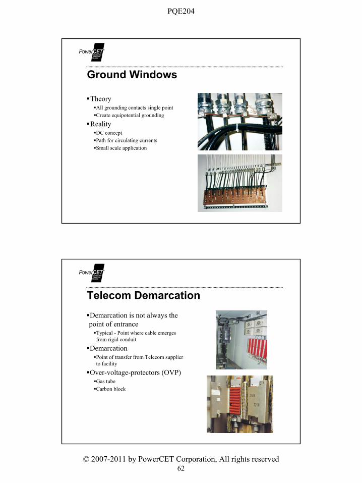
Ground Windows
TheoryAll grounding contacts single pointCreate equipotential grounding
RealityDC conceptPath for circulating currentsSmall scale application
Telecom DemarcationDemarcation is not always the point of entrance
Typical - Point where cable emerges from rigid conduit
DemarcationPoint of transfer from Telecom supplier to facility
Over-voltage-protectors (OVP)Gas tubeCarbon block

PQE204
© 2007-2011 by PowerCET Corporation, All rights reserved63
Protector & Sheath Grounding
Telco Protector Grounding 1Will Not Work -- BAD!!!!
INCOMING TELEPHONE LINES
CABLE SHEATHGROUND
PROTECTORGROUND
TOMODEMS
TELEPHONEPROTECTOR
INCOMING
TELEPHONE LINES
CABLE SHEATH
GROUND
PROTECTORGROUND
TOMODEMS
TELEPHONE
PROTECTOR
?
Common -- May Not Work

PQE204
© 2007-2011 by PowerCET Corporation, All rights reserved64
Telco Protector Grounding
Better -- Might Even Work!Separate grounding paths
–Sheath & protectors–Grounding point part of building
grounding electrode system
Placement is critical–Too close to load and secondary
protectors will fire rather than intended primary protectors
INCOMING TELEPHONE LINES
CABLE SHEATHGROUND
PROTECTORGROUND
TOMODEMS
TELEPHONEPROTECTOR
VERTICALSTEEL
Common trenchBell recommendations
1 foot separation minimumBonding every 1K feet
TIFTelephone Influence FactorHarmonic content affects data and voice signals
Coupling to Communications
Comm
AC
PQE204
© 2007-2011 by PowerCET Corporation, All rights reserved65
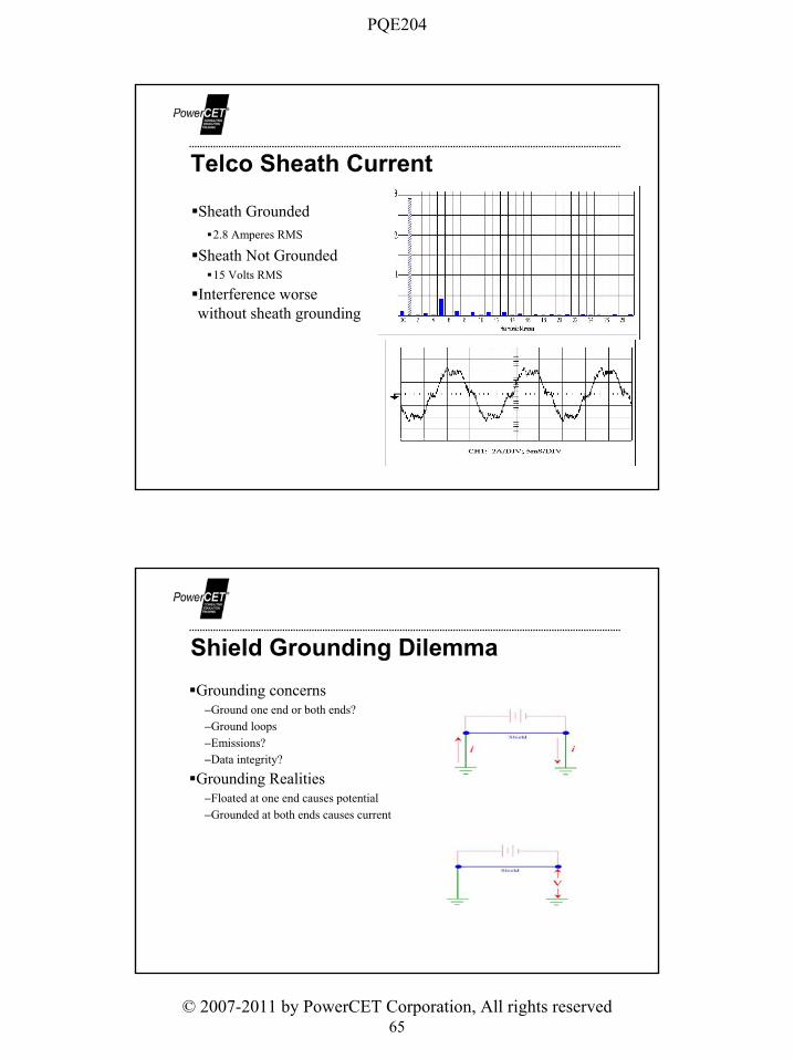
Telco Sheath Current
Sheath Grounded2.8 Amperes RMS
Sheath Not Grounded15 Volts RMS
Interference worse without sheath grounding
Shield Grounding DilemmaGrounding concerns
–Ground one end or both ends?–Ground loops–Emissions?–Data integrity?
Grounding Realities–Floated at one end causes potential–Grounded at both ends causes current

PQE204
© 2007-2011 by PowerCET Corporation, All rights reserved66
Shield Grounding Surge Test
8 x 20 uS Pulse– 1000Vpk – 500Apk
100kHz Ringwave– 6000Vpk– 500Apk
Test PulseCoax Current = 42ApkCenter pin voltage = 4.88Vpk

PQE204
© 2007-2011 by PowerCET Corporation, All rights reserved67
Open ShieldCoax Current = 4.4ApkCenter pin voltage = 180Vpk
2" Drain Wire (Pig Tail)8 x 20 uS UnipolarCoax Current = 41.6ApkCenter pin voltage = 16Vpk
100kHz RingwaveCoax Current = 35.2ApkCenter pin voltage = 72Vpk

PQE204
© 2007-2011 by PowerCET Corporation, All rights reserved68
MOVCoax Current = 27.2ApkCenter pin voltage = 58Vpk
Shield Grounding Concerns
–Shields are intended to carry currentCurrent must flow to chassis without interruption
–Floated shieldsMay flash overMay leak high frequencies into "protected" circuits
–FCC testing Usually performed with shields grounded at each end
–Data circuit may be grounded at both endsRS-232 & RS-423

PQE204
© 2007-2011 by PowerCET Corporation, All rights reserved69
Grounding Complications
Sensitive EquipmentIsolated groundingSupplemental grounds
Sensitive Electronic EquipmentNEC 647 [2011]
–Originally intended for audio studios --now Industrial/commercial applications
Requirements–Separately derived system–2 pole breakers–2.5% & 1.5% feeder/branch circuit voltage drop
–All 15 & 20 amps circuits must be GFCI protected
–Ground bus label -- Technical Power–IG receptacles allowed–Three phase applications require the use of 6 phase transformers

PQE204
© 2007-2011 by PowerCET Corporation, All rights reserved70
Isolated Grounding (IG)
Isolated grounding receptacles–NEC 250-146(D) [2011]
Isolated grounding passing through panelboards–NEC 408.40 Exception [2011]
Grounding must terminate within the derived service
IG vs Regular Receptacle
NEUTRALGROUNDEDCONDUCTORSILVER SCREW
GROUNDGROUNDINGCONDUCTORGREEN SCREW
HOTUNGROUNDEDCONDUCTORBRONZE SCREW
IG Receptacle Regular Receptacle
NEUTRALGROUNDEDCONDUCTORSILVER SCREW
GROUNDINGCONDUCTOR
GREEN SCREW
HOTUNGROUNDEDCONDUCTORBRONZE SCREW
EQUIPMENTGROUND
RECEPTACLEGROUND

PQE204
© 2007-2011 by PowerCET Corporation, All rights reserved71
IG Application• IG Normal application
– IG passes back through panels to service origin.
– Grounding wire size must increase to match ampacity of panels it passes through.
• Derived service– IG must terminate at the
derived service.– Stepdown transformer is the
derived service, not the main electrical entrance.
IG Position – Reality CheckNormal distribution wiring spreads incoming signals across many circuits.IG circuit extending back to service entrance assures larger signals at "protected" load.

PQE204
© 2007-2011 by PowerCET Corporation, All rights reserved72
-V = L(di/dt) -- mutual inductanceFunctions as a 1:1 transformerIG use may contribute to "ground loops"
IG Circuit Coupling
IG #2
IG #1
DATACABLE
GROUNDLOOP
IG Circuit Induced VoltagePhase current & induced chassis voltage
Chassis voltage and data cable current
PQE204
© 2007-2011 by PowerCET Corporation, All rights reserved73
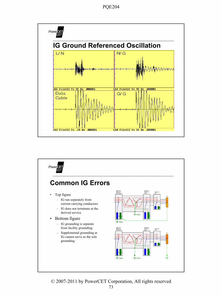
IG Ground Referenced Oscillation
Common IG Errors• Top figure
– IG run separately from current carrying conductors
– IG does not terminate at the derived service
• Bottom figure– IG grounding is separate
from facility grounding.– Supplemental grounding at
IG cannot serve as the sole grounding

PQE204
© 2007-2011 by PowerCET Corporation, All rights reserved74
Isolated Ground Path Problem• Common mode voltage
propagation - Source is equipment leakage current due to an overloaded EMI/RFI power supply filter.
• Effects include lockup, reset & blown serial ports.
12KV 480/277 Equipment208/120
V=IR
CMI
E=IZ
CMI
E=IZ
E=IZ
Isolated Grounding EffectsDestructive Common mode voltage Voltages develop across I/O circuits

PQE204
© 2007-2011 by PowerCET Corporation, All rights reserved75
Auxiliary (Supplementary) Grounding
Use is permitted–NEC 250.54 [2011]–Earth is not an effective grounding means and cannot be the sole grounding means as
specified in 250.4(A)(5) [2011] and 250.4(B)(4) [2011]–Supplemental grounding need not meet the electrode grounding provisions of NEC
250.50 or 250.53(C) [2011]
Auxiliary Grounding
H
N
H
N
High
Voltage
Low
Voltage
G
Equipment
Supplemental grounding provides a path for external ground referenced interference to enter a facilityAvoid use if at all possible

PQE204
© 2007-2011 by PowerCET Corporation, All rights reserved76
Supplementary Grounding Solutions
Re-derive & Re-reference
Bond to facility reference
DC Grounding
PQE204
© 2007-2011 by PowerCET Corporation, All rights reserved77
DC Grounding ConnectionsNEC 250.162(A) [2011]
–Two wire, direct-current systems–Operating voltage greater than 50V but less than 300V shall be grounded
NEC 250.162(B) [2011]–Three wire, direct-current systems–The neutral shall be grounded
NEC 250.164 [2011]–Point of connection for direct-current systems–Grounding must occur at the first system disconnecting means and not at individual
services or at any point of use in the premises wiringNEC 250.166 [2011]
–Size of Direct-Current Grounding ElectrodeNEC 250.169 [2011]
–Ungrounded Direct-Current Separately Derived Systems
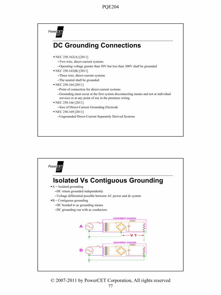
Isolated Vs Contiguous GroundingA = Isolated grounding
–DC return grounded independently–Voltage differential possible between AC power and dc system
B = Contiguous grounding–DC bonded to ac grounding means–DC grounding run with ac conductors
PQE204
© 2007-2011 by PowerCET Corporation, All rights reserved78
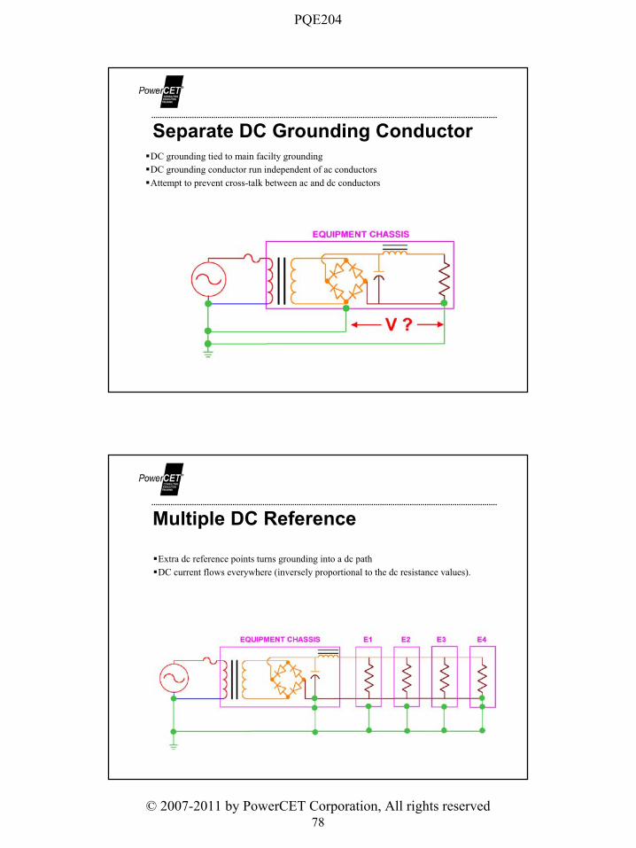
Separate DC Grounding ConductorDC grounding tied to main facilty groundingDC grounding conductor run independent of ac conductorsAttempt to prevent cross-talk between ac and dc conductors
Multiple DC Reference
Extra dc reference points turns grounding into a dc pathDC current flows everywhere (inversely proportional to the dc resistance values).

PQE204
© 2007-2011 by PowerCET Corporation, All rights reserved79
DC Systems and SRGProvides an installation consistent with the IEEE Emerald Book
DC Bus GroundingA = Isolated grounding
–DC return grounded independently–Voltage differential possible between AC power and dc system
B = Contiguous grounding–DC bonded to ac grounding means–DC grounding run with ac conductors

PQE204
© 2007-2011 by PowerCET Corporation, All rights reserved80
Separate DC Grounding ConductorDC grounding tied to main facilty groundingDC grounding conductor run independent of ac conductorsAttempt to prevent cross-talk between ac and dc conductors
Multiple DC ReferenceExtra dc reference points turns grounding into a dc pathDC current flows everywhere (inversely proportional to the dc resistance values).

PQE204
© 2007-2011 by PowerCET Corporation, All rights reserved81
Bonding Dual Power Sources
• Dual power sources used to ensure redundancy.
• Dual sources can be affected by “ground skew.” Ground skew refers to voltage differences between sources.
• Bonding the sources together as well as bonding to the BGES helps reduce ground loop currents through equipment powered from the dual sources.
AC & DC Sources
• AC & DC sources must also be bonded to the BGES to reduce common mode potentials in equipment powered from the sources.
• Supplemental DC return bonds to ground cannot be placed at equipment. This causes unwanted DC current flow throughout the facility.
PQE204
© 2007-2011 by PowerCET Corporation, All rights reserved82
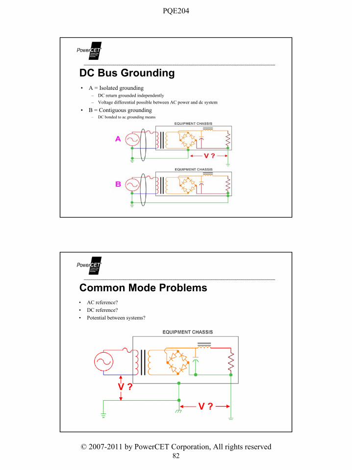
DC Bus Grounding• A = Isolated grounding
– DC return grounded independently– Voltage differential possible between AC power and dc system
• B = Contiguous grounding– DC bonded to ac grounding means
Common Mode Problems• AC reference?• DC reference?• Potential between systems?

PQE204
© 2007-2011 by PowerCET Corporation, All rights reserved83
Separate DC Grounding Conductor• DC grounding tied to main facilty grounding• DC grounding conductor run independent of ac conductors• Attempt to prevent cross-talk between ac and dc conductors
Multiple DC Reference
• Extra dc reference points turns grounding into a dc path• DC current flows everywhere (inversely proportional to the dc resistance values).

PQE204
© 2007-2011 by PowerCET Corporation, All rights reserved84
SRG & DC Systems
SRG & AC Systems

PQE204
© 2007-2011 by PowerCET Corporation, All rights reserved85
Misapplied SRG
• Attempt to reference equipment independently of facility grounding.
• Violates NEC.– SRG not bonded to BGES per
NEC 645.– SRG serves as sole grounding
means independent of SRG.
Unwanted Ground Current

PQE204
© 2007-2011 by PowerCET Corporation, All rights reserved86
Stray CurrentOpen NeutralInterconnected utility neutral and communications groundingCoupling to communications circuits
Utility Distribution Related
Utility Stray Vs Open Neutral Currents

PQE204
© 2007-2011 by PowerCET Corporation, All rights reserved87
Interconnected Utility Neutrals
High Voltage
Low Voltage
Interconnected Neutral
Telco & CATV
H H
N
High
Voltage
Low
Voltage
G
Utility TransformersL/G Primary L/L Primary

PQE204
© 2007-2011 by PowerCET Corporation, All rights reserved88
N/G bondsN/G reversalsDirect use of grounding as a returnCoupling and induction
Facililty Related Ground Current
Neutral/Ground Bonds
Lne
Neutral
Eqpt Grounding ConductorN-GBond
EGC = Equipment Grunding Conductor
"Isolated" Ground, Ground Rod, Cold-Water-Pipe Ground, etc.
Earth Ground(Main Building Electrical Ground)
Panelboard
Sub-panel
A
B
C
D
E
LEGEND:1
2
F
UtilizationEquipment
DataLink
Load CurrentNeutral Return Current
EGC

PQE204
© 2007-2011 by PowerCET Corporation, All rights reserved89
End User Solution to Ground Loops
Disconnected N/G bond at power distribution unitViolates codeSafety hazardPerformance problemCertainly not the correct solution to a problem
Neutral and Ground Problems
Load
AC#1
AC#2
Load#1
Load#2
Crossed neutrals N/G reversal

PQE204
© 2007-2011 by PowerCET Corporation, All rights reserved90
Grounding Conductors & Current
Phase A
Phase B
Phase C
Grounded conductor problem Induced current due to grounded conductor placement
Interference & Ground Loop Measurements

PQE204
© 2007-2011 by PowerCET Corporation, All rights reserved91
Tracing Ground Currents
Zero Sum Measurements
H
N

PQE204
© 2007-2011 by PowerCET Corporation, All rights reserved92
Compare Sum & Neutral
Summing Bus Bars

PQE204
© 2007-2011 by PowerCET Corporation, All rights reserved93
Checking Branch Circuits
Check TransformersN/G bond is the ground fault return pointCurrent patterns help ID sources

PQE204
© 2007-2011 by PowerCET Corporation, All rights reserved94
AC GaussmeterMeasures flux density
–Milligauss & MicroTeslasProblems arising from flux density
–CRT waver–Induced current flow in data cables
Great tool to ID ground loopsEasy to useSingle axis vs triaxial
Digitizing rate -- 100MS/s & higherBandwidth -- 100MHz & higherVertical resolution -- 8 bit or betterSingle channel triggering
Some scopes may have or-gate triggering on multiple channels
Single ended signal acquisitionDifferential measurements require multiple channels or external devices.
Extended monitoring capabilities–Metratek software
Stores triggered waveforms & rearms scopeDFT of acquired waveforms
Digital Storage Oscilloscope

PQE204
© 2007-2011 by PowerCET Corporation, All rights reserved95
High Frequency MeasurementsEverything grounded - interference voltages are small - difficult to distinguish from normal equipment operating noise.Currents much larger, easier to measureCouple using high-frequency transformerDigital storage oscilloscope and spectrum analyzer
Conventional Current Transformers• Fluke, AEMC• Multiple ranges
– 1mV/A– 10mV/A– 100mV/A
• Voltage output versus current output

PQE204
© 2007-2011 by PowerCET Corporation, All rights reserved96
Hall Effect Current Probes
• AEMC, Fluke• May have multiple ranges• Provides a proportional voltage output
for DC currents• AC currents can also be recorded• Requires zero adjustment
• Calibration required
High Frequency CTs
Commercial productsManufacturers
–EMCO, Tegam, Fischer Custom Communications, Amplifier Research
Intended use–50 Ohm interface–Scopes & spectrum analyzers
Range–100kHz to 100MHz–1MHz to 1GHz

PQE204
© 2007-2011 by PowerCET Corporation, All rights reserved97
Line Decouplers• Oneac, PowerVAR• Depending upon model may have
– L/N low frequency output– High frequency L/N and/or N/G
output– Bandwidth typically from kHz to
low MHz• Isolates scope from measurement point• Converts single ended input into
differential
Plate Antenna
Construction– Metal top and bottom– Plastic sides– Probe
10MegOhm – 10xTotal capacitance 35pF
– Intended useDigital storage scopesRecord radiated signals, cable potentials, floor potentials

PQE204
© 2007-2011 by PowerCET Corporation, All rights reserved98
Commercial Loop Antenna
Manufacturers– EMCO, Antenna Research
Frequency range– depends upon model
Ferrite Rod Antennas
Construction– 6" ferrite rod– 100 turns of 24 gauge telephone type
wire– BNC fitting
Termination provided by scopeFrequency range
– 50/60Hz to low kHz
PQE204
© 2007-2011 by PowerCET Corporation, All rights reserved99
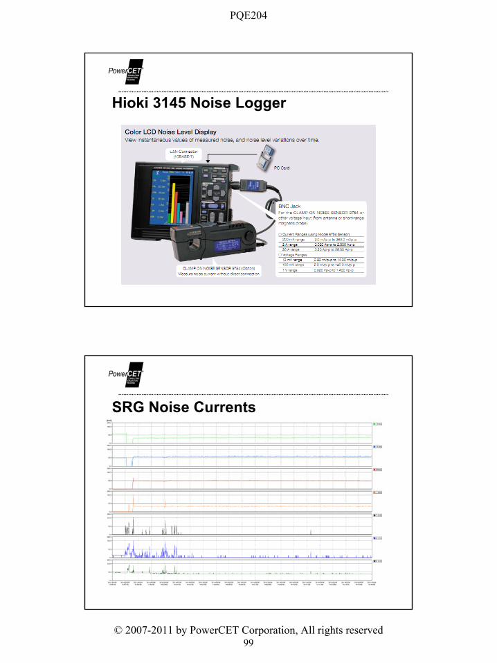
Hioki 3145 Noise Logger
SRG Noise Currents

PQE204
© 2007-2011 by PowerCET Corporation, All rights reserved100
Largest Signal• Voltage from chassis to plug strip mounted on the cabinet with isolated plastic standoffs.• Equipment in cabinet mounted on teflon glides.• Solution was to bond the plug strip to the cabinet.
Conclusion

PQE204
© 2007-2011 by PowerCET Corporation, All rights reserved101
Grounding Items to Avoid Supplementary grounding at equipment
Parallel to service entrance groundingConduit killers
No grounding wire – loose connectionsNeedless IG use
Grounding bypass of separately derived sourceGrounding "antennas“
Daisy chain grounding wires in workstation clustersLift or defeat data cable shielding of disconnect pin 7 for RS-232-C
N/G bond removal at transformers to stop ground loopsAvoid grounding differentials within facilities
Control interference at point of origin
Grounding Do'sAugment service entrance grounding when needed
–Match the surroundingsEnsure grounding at wye-to-wye service transformersEnsure grounding for padmount transformers inside facilitiesUse parity grounding for branch circuitsIntegrate facility grounding into a "Grounding electrode system“Remember Kirchoff's lawsUse Faraday concept for facility groundingEmploy reference grids in raised floor environments

PQE204
© 2007-2011 by PowerCET Corporation, All rights reserved102
Concluding Statements
Current Flows in Paths - Kirchoff's Laws PrevailGround is a path - not a terminus - and understanding the paths is the key to good groundingInterference can compromise good grounding – if something looks ugly – fix it!Electrical Codes cannot be compromised by grounding practices


![Station Grounding - NAØTC] 2/5/2011 5 Ham Station Grounding ... •National Electrical Code (NEC) ... equipment bonding configurations are used to serve](https://img.dokumen.tips/doc/110x75/5afca7827f8b9a994d8c63cb/station-grounding-natc-5-ham-station-grounding-national-electrical-code.jpg)


