Embed Size (px)
Citation preview

Fabrication and MaintenancePRO Range

Twitter – Atlas Copco Industrial Tools & Solutions Linkedin – Atlas Copco Industrial Tools & Solutions Youtube – Atlas Copco Industrial Tools & Solutions
11www.atlascopco.com 1
Contents
IMPACT WRENCHES 6
RATCHET WRENCHES 10
SCREWDRIVERS 14
DRILLS 18
ANGLE AND VERTICAL GRINDERS 22
DIE GRINDERS 26
SANDING & POLISHING 30
PERCUSSIVE TOOLS 38
AIR PREPARAITION UNITS 46
CONNECTORS AND COUPLINGS 54
HOSES 80
HOSE REELS 90
BLOW GUNS & TEST EQUIPEMENT 94
VIBRATION AND SOUND VALUES 96

22 www.atlascopco.com2
Conduct a visual inspection of the tool before use Check the tool, including hoses or fittings, for signs of damage and replace defect parts if necessary. Check for cracks in the sockets, grinding wheels, chisels, etc., and replace damaged parts if required.
Check the free speed of the tool
Make sure the measured speed at a pressure of 6.3 bar does not exceed the rated speed of the tool. Before checking the measured speed, always remove wheels, burrs, sockets, etc.
Use the right accessories
Always use the accessories recommended in the safety manual. Never use hand sockets with impact or ratchet wrenches. Never use a grinding wheel, burr, cone wheel, etc., marked with a speed lower than the speed of the grinder. Always disconnect the air tool before changing accessories.
Wear safety gear
Always use appropriate safety equipment, such as goggles and earplugs. When required, wear gloves, apron and helmet. When working with materials that produce airborne particles, be sure to wear a dust mask or similar protective gear and use other equipment, such as dust extractors, to control exposure to harmful substances.
Before grinding, test the tool
Test run the grinder in a protected area before starting work and after changing the wheel. Make sure that the space around is free from other people.
Maintain a safe work area
Keep other people at a safe distance away from your workspace while you use the tools. Beware of hoses on the walking or work surface. Always direct exhaust air away from yourself and others. Never use an air tool in explosive atmospheres. Stay away from electric wiring because an air tool is not insulated for contact with electrical power sources.
Safety tips
Below are few tips to increase power tool safety and help avoid injury and accidents. These tips, however, are no substitute for the PRO tools safety and instruction manuals.
Safe hand tool operation is a fundamental tenet of PRO tool design. All of our tools have features that safeguard operators against work-related injuries and machine-related hazards. But the best way to ensure hand tool safety is to ensure that operators use the recommended safety practices.
That is why each PRO tool comes with a safety and instruction manual that operators should read and follow when using our tools. For a copy of these manuals, contact your Atlas Copco reprasentative or visit www.atlascopco.com.
For more information on safe power tool operation, please refer to the rules for tool safety from these two organizations:Safety Code for Portable Air Tools, ANSI B186.1American National Standards Institute (ANSI)11 W. 42nd St, 13th floor, New York, NY 10036.
Further occupational health & safety information, see web sites:http://www.osha.gov (USA) http://europe.osha.eu.int (Europe)
How to use our tools safely
After workAlways disconnect your air tool after use.
Our tools come with a manual
33www.atlascopco.com
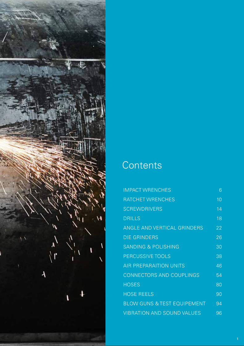
Tools for professionals
Some years ago, we took the high quality die-cast molds used to manufacture industrial tools for production lines and produced the PRO range of hand-held tools for light industry users.
The tools were an immediate success and we continuously expanded the range with tools that demanding industrial users need to get the job done.
Features and benefits
Design Attractive, comfortable to hold and ergonomic.
Robust Sturdy material, solid design, excellent
performer. PRO keeps on working and gets results.
Quality PRO comes with a long list of great features.
Power The work gets done in record time. It’s easy to handle tough jobs with PRO.
Warranty The assurance of quality and performance is a generous warranty.
Find more information regarding spare parts, service, dimentional drawings, sustainable productivity and general recomendations:
www.atlascopco.com

444 www.atlascopco.com
Impact Wrenches

55www.atlascopco.com
Low weight – High output
• Models with twin hammer impact mechanism for fast run down
• Models with composite housing for best power-to-weight ratio and with durable aluminum and magnesium housing
• Button controlled forward/reverse settings
• Easy one hand operation for pistol grip models
• Ergonomic handles with rubber grip

666 www.atlascopco.com
W2915
W2910 W2911 W2920
With easy operation the W29-series are your perfect partner for general assembly and tackling the toughest industrial jobs that requires high torque output.
These models features a twin hammer impact mechanism for fast run down with a composite housing for best power-to-weight ratio with four torque settings.
Easy one hand operation (Left or right handed) with button controlled torque setting (forward/reverse) with a ergonomic handle with anti-slip rubber grip.
Model
Bolt size mm
Square drive size in
Torque - Forward
Nm
Torque - Reverse
Nm
Torque Range
Nm
Free speed r/min
Weight kg
Air con- sumption
l/s
Rec. hose size mm
Air inlet thread BSP
Modeltype
Impactmechanism Ordering No.
W2910 M14 3/8” 310 500 150-400 6500 1.2 17 10 1/4'' Pistol Twin hammer 8434124850W2911 M14 1/2'' 370 500 150-400 7300 1.2 17 10 1/4'' Pistol Twin hammer 8434124851W2915 M16 1/2'' 710 1000 200-800 7700 2.0 18 10 1/4'' Pistol Twin hammer 8434124852W2920 M30 3/4'' 1400 1500 300-1450 5500 3.2 27 13 3/8'' Pistol Twin hammer 8434124853
Impact Wrenches
W29-series
Torque range (min/max) is a calculated value acc. To Skidmore. Performance is depending on air installation and type of bolted joint.
77www.atlascopco.com
W2410 W2411 W2412
W2420 W2425 W2428
Model
Bolt size mm
Square drive size in
Torque - Forward
Nm
Torque - Reverse
Nm
Torque Range
Nm
Free speed r/min
Weight kg
Air con-sump-tion l/s
Rec. hose size mm
Air inlet thread BSP
Modeltype
Impactmechanism Ordering No.
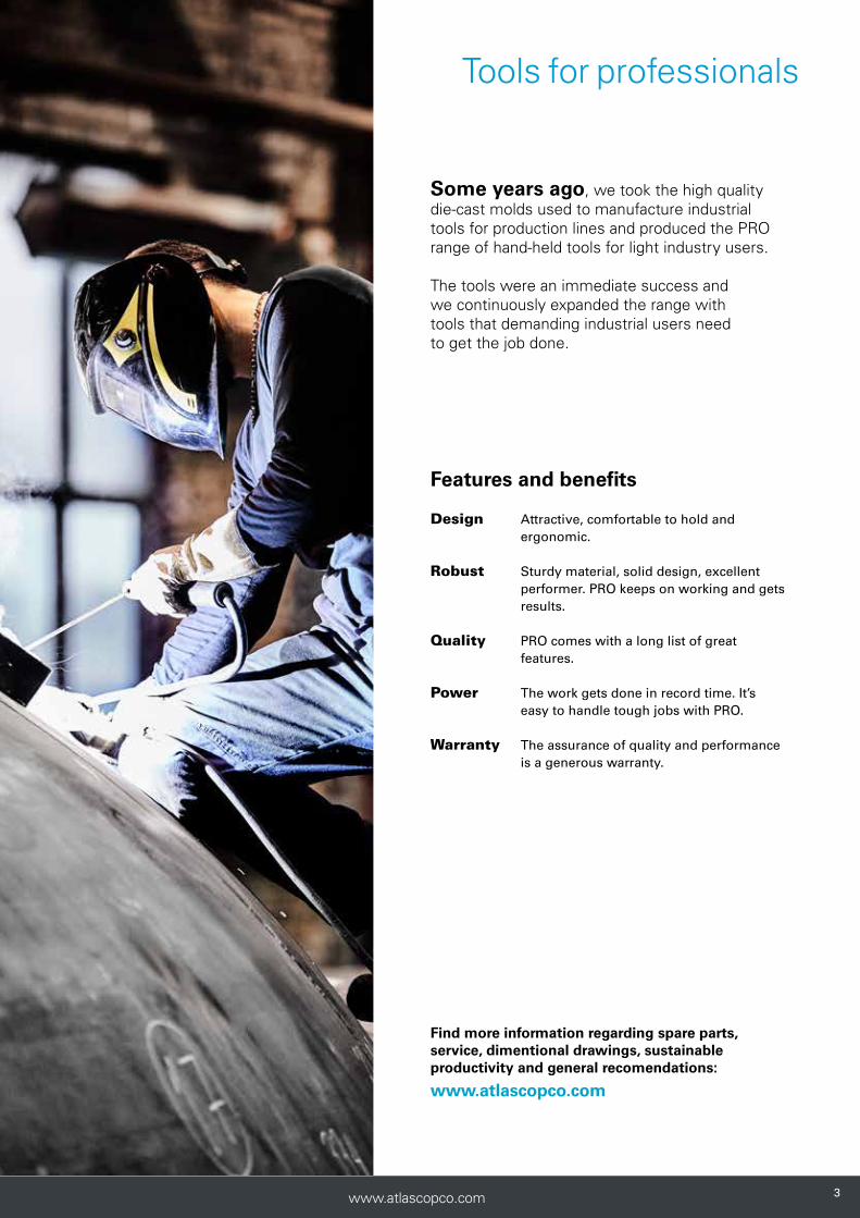
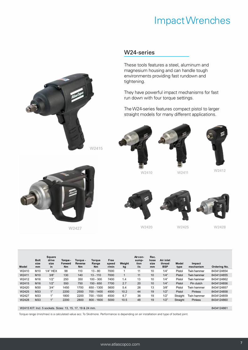
W2410 M10 1/4” HEX 98 110 13 - 80 7000 1 11 10 1/4” Pistol Twin hammer 8434124854W2411 M10 3/8” 130 140 13 - 110 7000 1 11 10 1/4” Pistol Twin hammer 8434124855W2412 M16 1/2” 250 350 100 - 300 7400 1.4 13 10 1/4” Pistol Twin hammer 8434124862W2415 M16 1/2” 550 750 150 - 650 7700 2.7 20 10 1/4” Pistol Pin clutch 8434124856W2420 M30 3/4” 1450 1700 650 - 1300 5600 5.4 26 13 3/8” Pistol Twin hammer 8434124857W2425 M33 1” 2200 2550 700 - 1400 4500 10.2 44 19 1/2” Pistol Pinless 8434124858W2427 M33 1” 1800 2200 700 - 1500 4500 6.7 36 19 1/2” Straight Twin hammer 8434124859W2428 M33 1” 2200 2800 800 - 1600 5000 10.5 48 19 1/2” Straight Pinless 8434124860
W2415 KIT: Incl. 5 sockets. Sizes: 13, 15, 17, 19 & 24 mm. 8434124861
Impact Wrenches
These tools features a steel, aluminum and magnesium housing and can handle tough environments providing fast rundown and tightening.
They have powerful impact mechanisms for fast run down with four torque settings.
The W24-series features compact pistol to larger straight models for many different applications.
W24-series
W2427
W2415
Torque range (min/max) is a calculated value acc. To Skidmore. Performance is depending on air installation and type of bolted joint.
888 www.atlascopco.com8
Ratchet Wrenches

99www.atlascopco.com 9
• Great power-to-weight ratio
• Robust composite housing
• Rubber grip on handle for insulation and comfort
• Easy switch between forward and reverse
• 360 degree adjustable air exhaust
9
Compact and powerful!

101010 www.atlascopco.com10
Ratchet Wrenches
W2620 / W2621
PRO ratchet wrenches are powerful, reversible and designed for easy access in confined spaces.
The tools are light, comfortable and easy to work with, due to their robust composite housing and high power-to-weight ratios.
W26-series

1111www.atlascopco.com 11
Ratchet Wrenches
W2610 / W2611 W2630 / W2631
Model Bolt size
mm
Square drive size
in
Torque range
Nm
Free speed r/min
Weight kg
Length mm
Air con-sumption
l/s
Rec. hose size mm
Air inlet thread BSP Ordering No.
W2611 M8 1/4'' 4-40 280 0.55 192 9 10 1/4'' 8431 0350 11W2610 M8 3/8'' 4-40 280 0.55 192 9 10 1/4'' 8431 0350 10W2621 M12 3/8'' 5-68 170 1.1 271 10 10 1/4'' 8431 0350 21W2620 M12 1/2'' 5-68 170 1.1 271 10 10 1/4'' 8431 0350 20W2631 M14 3/8'' 25-80 200 1.2 307 11 10 1/4'' 8431 0350 31W2630 M14 1/2'' 25-80 200 1.2 307 11 10 1/4'' 8431 0350 30
Torque range (min/max) is a calculated value acc. To Skidmore. Performance is depending on air installation and type of bolted joint.

121212 www.atlascopco.com12
Screwdrivers

1313www.atlascopco.com 13
Machinescrew 4.8
Machine screw 8.8
Thread forming screw-M
Thread forming
screw-ST
Thread forming screw-ST plastic
Self drilling screw-S
Wood screw
Impact clutch
Direct drive ◊ ◊ ◊ ◊
Slip clutch ◊ ◊ ◊ ◊
Shut-off clutch ◊ ◊
Recommended
◊ Usable
Selection guide
• Slip-clutch for torque control. Once the desired torque is reached the coupling slips
• Well balanced and ergonomic
• Soft-start trigger for smooth operation
• 360 degree adjustable air exhaust
• Silent
Speed and precision!
141414 www.atlascopco.com
Screwdrivers
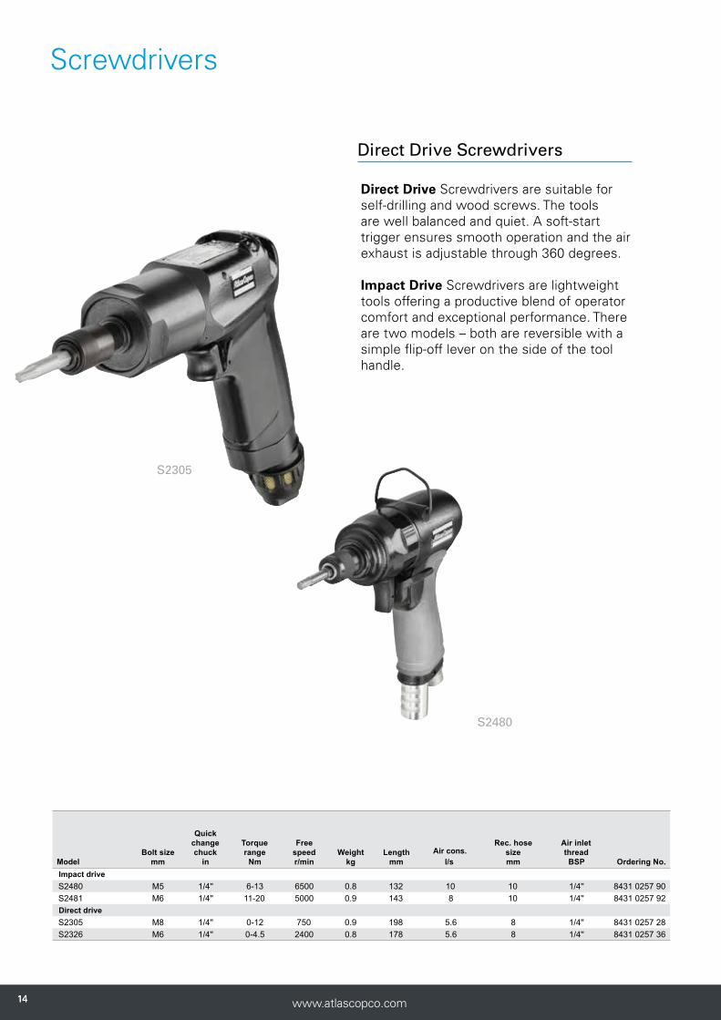
S2480
S2305
Direct Drive Screwdrivers are suitable for self-drilling and wood screws. The tools are well balanced and quiet. A soft-start trigger ensures smooth operation and the air exhaust is adjustable through 360 degrees.
Impact Drive Screwdrivers are lightweight tools offering a productive blend of operator comfort and exceptional performance. There are two models – both are reversible with a simple flip-off lever on the side of the tool handle.
Model Bolt size
mm
Quick change chuck
in
Torque range
Nm
Free speed r/min
Weight kg
Length mm
Air cons.l/s
Rec. hose size mm
Air inlet thread BSP Ordering No.
Impact driveS2480 M5 1/4'' 6-13 6500 0.8 132 10 10 1/4'' 8431 0257 90S2481 M6 1/4'' 11-20 5000 0.9 143 8 10 1/4'' 8431 0257 92Direct driveS2305 M8 1/4'' 0-12 750 0.9 198 5.6 8 1/4'' 8431 0257 28S2326 M6 1/4'' 0-4.5 2400 0.8 178 5.6 8 1/4'' 8431 0257 36
Direct Drive Screwdrivers

1515www.atlascopco.com
Screwdrivers
S2308-C / S2309-C / S2310-C
S2340-C / S2360-C / S2370-CS2450-P / S2451-P / S2452-P S2416-L / S2426-L / S2428-L
S2307-CE external adjustable clutch
Shut-off Screwdrivers offer impressively high torque accuracy. Our fast shut-off models deliver smooth performance and high quality tightening.
Slip-Clutch Screwdrivers provide an implied pulsating force, or slip, once you reach the desired torque.
Both versions feature adjustable torque settings, trigger and push start for pistol grips, and lever and push start for straight models.
Model
Screw capa-city mm
Quick change chuck
in
Torque range
Nm
Free speed r/min
Weight kg
Length mm
Air cons. at free speed
l/s
Rec.hose size mm
Air inlet
thread BSP
Starting method
Ordering No. Push
Push and trigger/
leverTrigger/
leverSlip clutchS2308-C M6 1/4'' 2.5-11 950 1.1 225 8.4 10.0 1/4'' - ● - 8431 0257 20S2309-C M5 1/4'' 1.5-7.5 1200 1.0 245 7.0 8.0 1/4'' - ● - 8431 0257 22S2310-C M5-8 1/4'' 2-15 800 1.1 225 8.5 10,0 1/4'' - ● - 8431 0257 24S2307-CE M6 1/4'' 2.5-10 900 1.2 245 8.4 10.0 1/4'' - - ● 8431 0257 26S2340-C M3 1/4'' 0.5-2 1300 0.9 250 4.0 6.3 1/4'' - ● - 8431 0257 40S2360-C M4-5 1/4'' 1.3-7 700 0.9 260 4.0 6.3 1/4'' - ● - 8431 0257 60S2370-C M5 1/4'' 2-6 1300 0.9 250 4.0 6.3 1/4'' - ● - 8431 0257 70Shut offS2426-L M4 1/4'' 1.2-2.6 1500 0.9 230 6.0 8,0 1/4'' - ● - 8431 0257 80S2428-L M4-5 1/4'' 3.5-7 700 1.0 242 6.0 8,0 1/4'' ● - - 8431 0257 81S2416-L M3 1/4'' 0.5-1.6 1500 0.9 230 6.0 8,0 1/4'' - ● - 8431 0257 82S2450-P M5 1/4'' 2.4-5 1100 1.1 225 6.0 8,0 1/4'' - - ● 8431 0257 84S2451-P M5 1/4'' 3.5-7.5 800 1.1 250 7.0 8,0 1/4'' - ● - 8431 0257 86S2452-P M6 1/4'' 3.5-12 580 1.1 250 7.0 8,0 1/4'' - ● - 8431 0257 87
Shut-off Screwdrivers

161616 www.atlascopco.com16
Drills
16

1717www.atlascopco.com 17
• Well balanced and ergonomic
• High spindle accuracy
• Soft-start throttle
• Silent
• Air exhaust through handle
• Oil-free
• Available with key or quick chuck
Selection guide
a) Drill size larger than standard chuck capacity.
Superior hole quality!
17
Model r/minMild steel
20–30 m/minAlloy steel 5–15 m/min
Cast iron 15–20 m/min
Aluminum & bronze 50–80 m/min
Wood and board 80–150 m/min
Composite 50–100 m/min
D2112 5,400
Dri
ll d
im. /
mm
1.0–2.0 - - 2.5–5.0 4.0–8.0a 1.0–5.0
D2116/D2160 2,400 2.5–6.0 1.0–3.0 2.0–4.0 8.0–13.0a 8.0–13.0a -
D2163 2,000 2.5–6.0 1.0–3.0 2.0–4.0 8.0–13.0a 8.0–13.0a -
D2121 750 8.0–13.0 3.0–8.0 7.0–13.0 - - -
D2148-R 750 8.0–13.0 3.0–8.0 7.0–13.0 - - -

181818 www.atlascopco.com
Drills
D2112/D2116
D2121/D2121Q
PRO drills are all-metal and designed with operator comfort in mind. They come in three different versions, pistol grip, straight grip and angle grip. They are available with key chuck or quick change chuck.
D2112Q/D2116Q D2160Q
D2163
D21-Series
1919www.atlascopco.com
Drills
Model
Max free speed r/min
Max output
kw
Chuck capacity
mmWeight
kg
Air cons.at max output
l/s
Rec. hose size mm
Air inlet thread BSP
Drill type handle
Reversible
Chuck type
Ordering No.Pistol Straight Angle Key Quick
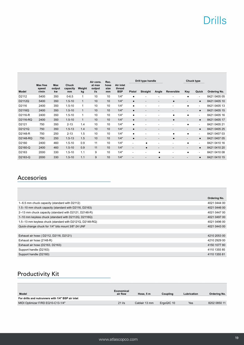
D2112 5400 350 0-6.5 1 10 10 1/4'' ● - - - ● - 8421 0405 05D2112Q 5400 350 1.5-10 1 10 10 1/4'' ● - - ● - ● 8421 0405 10D2116 2400 350 1.5-10 1 10 10 1/4'' ● - - - ● - 8421 0405 13D2116Q 2400 350 1.5-10 1 10 10 1/4'' ● - - - - ● 8421 0405 15D2116-R 2400 350 1.5-10 1 10 10 1/4'' ● - - ● ● - 8421 0405 16D2116-RQ 2400 350 1.5-10 1 10 10 1/4'' ● - - ● - ● 8421 0405 17D2121 750 350 2-13 1.4 10 10 1/4'' ● - - - ● - 8421 0405 21D2121Q 750 350 1.5-13 1.4 10 10 1/4'' ● - - - - ● 8421 0405 25D2148-R 750 250 2-13 1.5 10 10 1/4'' ● - - ● ● - 8421 0407 03D2148-RQ 750 250 1.5-13 1.5 10 10 1/4'' ● - - ● - ● 8421 0407 05D2160 2400 460 1.5-10 0.9 11 10 1/4'' - ● - - ● - 8421 0410 16D2160-Q 2400 460 1.5-10 0.9 11 10 1/4'' - ● - - - ● 8421 0410 20D2163 2000 330 1.5-10 1.1 9 10 1/4'' - - ● - ● - 8421 0410 08
D2163-Q 2000 330 1.5-10 1.1 9 10 1/4'' - - ● - - ● 8421 0410 15
ModelEconomical
air flow Hose, 5 m Coupling Lubrication Ordering No.For drills and nutrunners with 1/4" BSP air inlet
MIDI Optimizer F/RD EQ10-C13-1/4" 21 l/s Cablair 13 mm ErgoQIC 10 Yes 8202 0850 11
Ordering No.
1–6.5 mm chuck capacity (standard with D2112) 4021 0444 001.5–10 mm chuck capacity (standard with D2116, D2163) 4021 0446 00
2–13 mm chuck capacity (standard with D2121, D2148-R) 4021 0447 001–10 mm keyless chuck (standard with D2112Q, D2116Q) 4021 0497 001.5–13 mm keyless chuck (standard with D2121Q, D2148-RQ) 4021 0496 00Quick-change chuck for 1/4'' bits mount 3/8''-24 UNF 4021 0443 00
Exhaust air hose ( D2112, D2116, D2121) 4210 2053 00Exhaust air hose (2148-R) 4210 2929 00Exhaust air hose (D2163, D2163) 4150 1077 80Support handle (D2163) 4110 1355 85Support handle (D2160) 4110 1355 81
Productivity Kit
Accesories
202020 www.atlascopco.com
Angle and Vertical Grinders
2020

2121www.atlascopco.com 21
Increase your productivity• Speed governor for optimal process
speed and highest productivity
• Great power-to-weight ratio
• Rubber grip for insulation and comfort
• Safety lever to avoid unintentional starts
• Adjustable wheel guard

22 www.atlascopco.com22
Angle and Vertical Grinders
22
G2408-125
G2511 G2588 G2415
PRO grinders are a popular choice for sur-face preparation in general industry. They are lightweight tools that deliver all the power you need, yet easy to handle.
For additional comfort they are equipped with a rubber handle grip and adjustable wheel guard. All grinders except the G2408-series are equipped with a speed governor to ensure the grinding wheel operates at optimum speed.
The vertical grinders are suitable for rough grinding and cutting off operations on open surfaces.
Model
Max free
speed r/min
Max output
kW
Max wheel
dia mm
Spindle thread
Spindle length
mmWeight
kg
Height over
spindle mm
Air cons. at max output
l/s
Air cons. at free speed
l/s
Rec. hose size mm
Air inlet thread BSP Ordering No.
G2408-100 12000 0.35 100 UNF 3/8" 17 0.9 61 9 13 10 1/4'' 8423 0314 60G2408-115 12000 0.35 115 UNF 3/8" 17 0.9 61 9 13 10 1/4'' 8423 0314 78G2408-125 12000 0.35 125 UNF 3/8" 17 0.9 61 9 13 10 1/4'' 8423 0314 80G2511-125 12000 0.9 125 M14 18 1.8 61 20 17 13 3/8'' 8423 0317 00G2511-115 12000 0.9 115 M14 18 1.8 61 20 17 13 3/8'' 8423 0317 01G2511-100 13300 0.9 100 UNF 3/8" 17 1.8 61 20 17 13 3/8'' 8423 0317 02G2588-230-M14 6600 1.7 230 M14 17 2.4 91.5 32 17 16 1/2'' 8423 0132 82G2588 7200 1.7 180 M14 17 2,4 91.5 32 17 16 1/2" 8424 0132 87G2588-180-M14 8500 1.7 180 M14 14 2.4 91.5 32 17 16 1/2'' 8423 0132 88Vertical GrindersG2415 8500 1.1 180 UNC 5/8" 30 2.7 198 23 21 16 1/2'' 8423 2522 49G2416 6000 0.9 180 UNC 5/8" 30 2.7 198 30 18 16 1/2'' 8423 2522 56
G24/25-series
22222222 www.atlascopco.com

www.atlascopco.com 2323
Angle and Vertical Grinders
Accessories Grinders G2408 G2511 G2515 G2415 G2416 G2588
Flange depressed center wheel (incl. with tool) - - - 4170 0219 87 4170 0219 87 4150 1160 02Flange cut-off wheel (incl. with tool) - - - 4170 1133 87 4170 1133 87 -Flange nut 4150 1160 00 4150 1160 02 4112 3002 11 - - -Flange nut, quick change Fixtec - M14 4150 1929 00 4150 1929 00Support handle 4110 1355 85 4110 1355 85 4111 3002 97 4110 1355 87 4110 1355 87 4110 1355 89Vibration damped handle 4150 1521 80 4150 1521 80 - - - 4150 1521 80Cut-off kit - - 4112 1553 90 - - -Soft pad Ø 180 mm - - - 4170 0756 80 4171 0756 80 -Stiff pad Ø 180 mm - - - 4170 0757 80 4171 0757 80 -Steel wire brush Ø 115 mm for 5/8" spindle - - - - 4170 0491 00 -Steel wire brush Ø 140 mm for 5/8" spindle - - - - 4170 0685 00 -Attachment set for Ø 115 mm wire brush - - - - 4170 0459 81 -Attachment set for Ø 140 mm wire brush - - - - 4170 0550 80 -
Add on spot suctionØ 125 mm 3780 4032 14 3780 4032 14 - - - -Ø 180-230 mm - - 3780 4032 12 3780 4032 12 3780 4032 12 3780 4032 12
Alu-cut guard kit -Saw blade, Ø 125 mm for cutting applic, 30 teeth, 2 mm thick - 4112 1164 00 - - - -Saw blade, Ø 125 mm for milling applic, 6 teeth, 4 mm thick - 4112 1162 00 - - - -
MultiFlex 8202 1350 20 8202 1350 22 8202 1350 22 8202 1350 24 8202 1350 24 8202 1350 24
MultiFlex
Steel wire brush Ø 115 mm
Attachment set for steel wire brush Ø 115 mm
Steel wire brushØ 140 mm
Attachment set for steel wire brush Ø 140 mm
Accesories
232323www.atlascopco.com

242424 www.atlascopco.com24
Die Grinders
24

2525www.atlascopco.com 25
Powerful and scatter-free• Great power-to-weight ratio
• Speed governor for optimal grinding speed
• Safety start lever
• Unique spindle suspension that prevents burr chatter and minimizes vibration transfer

262626 www.atlascopco.com
Die Grinders
26
G2414
PRO die grinders are robust tools for grinding and finishing work in general industry.
G2414/G2424 are equipped with speed governors for optimal process speed togheter with a unique dampening system that are reducing the vibrations for the operator. Extreme working conditions place high demands on tools being used. We offer G2417/G2427 with a heavy duty, all-steel body that will fulfil these requirements.
G2412-1
G2422-1 G2417
Model
Max free speed r/min
Max output
kWLength
mmWeight
kg
Air cons. at max output
l/s
Air cons.at free speed
l/s
Rec. hose size mm
Air inlet
thread BSP 6 mm 1/4'' Ordering No.
Straight - StandardG2412-1 20000 0.35 178 0.5 10.3 13.0 10 1/4'' ● ● 8423 0312 21G2414-S085 8500 0.50 215 0.8 13.0 4.2 13 3/8'' ● ● 8423 0312 58G2414 S120 12000 0.75 215 0.8 16.0 5.3 13 3/8'' ● ● 8423 0312 57G2414 S150 15000 0.85 215 0.8 18.0 7.2 13 3/8'' ● ● 8423 0312 56G2414 S200 20000 0.90 215 0.8 19.0 9.0 13 3/8'' ● ● 8423 0312 30G2414 S250 25000 0.95 215 0.8 21.0 14.5 13 3/8'' ● ● 8423 0312 29Straight - All steel bodyG2417-S120 12000 0.66 213 1.2 13.8 4.0 13 3/8'' ● - 8423 0312 84G2417-S180 18000 0.82 213 1.2 17.4 7.0 13 3/8'' ● - 8423 0312 83G2417-S250 25000 0.86 213 1.2 18.5 11.0 13 3/8'' ● - 8423 0312 82Straight extendedG2422-1 20000 0.35 277 0.7 10.3 13.0 13 1/4'' ● ● 8423 0312 47G2424-S085 8500 0.44 315 1.0 13.0 4.2 13 3/8'' ● ● 8423 0312 61G2424 S120 12000 0.70 315 1.0 16.0 5.3 13 3/8'' ● ● 8423 0312 60G2424 S150 15000 0.75 315 1.0 18.0 7.2 13 3/8'' ● ● 8423 0312 59G2424 S200 20000 0.85 315 1.0 19.0 9.0 13 3/8'' ● ● 8423 0312 55G2424 S250 25000 0.90 315 1.0 21.0 14.5 13 3/8'' ● ● 8423 0312 62Straight extended - All steel bodyG2427-S250 25000 0.86 338 1.6 18.5 11.0 13 3/8'' ● - 8423 0312 86G2427-S180 18000 0.82 338 1.6 17.4 7.0 13 3/8'' ● - 8423 0312 87G2427-S120 12000 0.66 338 1.6 13.8 4.0 13 3/8'' ● - 8423 0312 88Straight - Standard - Low SpeedG2440 4300 0.55 216 0.9 5.7 7.0 10 1/4'' ● ● 8423 0312 20
Collet size
G24-series
26262626262626 www.atlascopco.com

2727www.atlascopco.com
Die Grinders
27
G2451
G2451 is a lightweight, high-speed die grinder for light grinding and precision work. It has a robust aluminum housing with a plastic cover and comes with an exhaust air hose.
Model Economical air flow Hose, 5 m Coupling Lubrication Ordering No.For percussive tools and grinders with 3/8" BSP air inlet incl. whip hoseMIDI Optimizer F/RD EQ10-R13-W 21 l/s Rubber 13 mm ErgoQIC 10 Yes 8202 0850 14For percussive tools and grinders, incl. whip hose, no tool nipple included
MIDI Optimizer F/RD EQ10-R13-W 21 l/s Rubber 13 mm ErgoQIC 10 Yes 8202 0850 15For grinders and nutrunners with 3/8" BSP air inletMIDI Optimizer F/RD EQ10-T13 21 l/s Turbo 13 mm ErgoQIC 10 Yes 8202 0850 17For grinders and nutrunners with 1/2" BSP air inletMIDI Optimizer F/R EQ10-T13 21 l/s Turbo 13 mm ErgoQIC 10 No 8202 0850 04MIDI Optimizer F/RD EQ10-T13 21 l/s Turbo 13 mm ErgoQIC 10 Yes 8202 0850 13
Productivity Kits
Model
Max free speed r/min
Max output
kWLength
mmWeight
kg
Air cons. at free speed
l/s
Rec. hose size
mm
Air inlet thread BSP 3 mm 1/8'' Ordering No.
G2451 80000 0.080 140 0.48 2.7 5 1/4'' ● ● 8423 0313 01Hose included
Collet size
For model G2412, G2414, G2422, G2424 Ordering No.
3 mm 4150 1049 816 mm 4150 1049 83*8 mm 4150 1049 841/8" 4150 1049 851/4" 4150 1049 88**Collet included with tool
For model G2451 Ordering No.
3 mm 4112 1380 00*1/8’’ 4112 1381 00*1/12” 4112 1381 01*Collet included with tool
Collet complete
For model G2417, G2427 Ordering No.
ColletsCollet Ø 1/4" 4150 0076 00Collet Ø 3 mm 4150 0081 00Collet Ø 5 mm 4150 0075 01Collet Ø 6 mm 4150 0075 00Collet Ø 8 mm 4150 0074 00Collet nut 4150 0760 00Collet holder and collet nut 4110 0844 90Extension 75 mm (3") 4150 0674 00
Accessories
2727272727www.atlascopco.com

282828 www.atlascopco.com
Sanding and polishing

2929www.atlascopco.com
For the optimal surface finish!• Great power-to-weight ratio
• Speed governor for optimal sanding speed
• Rubber grip on handle for insulation and comfort
• Safety start lever
• Spot suction kit available for clean and healthy working environment

3030 www.atlascopco.com
Sanding and polishing
Angle sanders
G2588
Model
Max free speed r/min
Max output
kW
Max pad dia
Spindlethread
Spindlelength
mmWeight
kg
Height over
spindle mm
Air cons. at max output
l/s
Air cons. at free speed
l/s
Rec. Hose Sizemm
Air inlet
threadBSP Ordering No.
G2588 S066 6600 1.7 230 UNC 5/8'' 24.5 2.4 87 32 17 16 1/2 8423 0132 80G2588 S085-M14 8500 1.7 180 M14 21 2.4 87 32 17 16 1/2 8423 0132 81
The G2588 Angle Sander is suitable for rough sanding when more power is needed. Light and powerful, this is a powerful tool for the application.
Focus on operator ergonomics and productivity Available in two speeds and spindle threads.
303030 www.atlascopco.com

31www.atlascopco.com
Sanding and polishing
Belt sanders
G2410/G2420 are suitable for precision sanding where access is difficult with conventional sanders.
The head rotation provides a versatile solution for many applications.
G2420
G2410
Model
Max free speed r/min
Max output
kW
Belt speed m/min
Belt dimension
mmWeight
kgAir cons.
l/s
Rec. hose size mm
Air inlet thread BSP Ordering No.
G2410 25000 275 1400 13x305 0.9 10 10 1/4'' 8423 0304 10G2410 Kit 25000 275 1400 13x305* 0.9 10 10 1/4'' 8423 0304 11G2420 22000 350 1500 19x520 1.0 11 10 1/4'' 8423 0304 20
*13x305 std, but also includes 6X305 and 13x305 felt belt arm
G2410 Accessories Ordering No.
Contact arm sanding belts 13 x 305mm (1/2’’x12’’)(std arm)
4112 3007 88
Contact arm sanding belts 3 & 6 x 305mm (1/8’’ & 1/4’’x12’’)
4112 3007 78
Contact arm felt belts 13 x 305mm (1/2’’x12’’)
4112 3007 79
Service kit motor 4081 0501 90
Service kit general 4081 0502 90
Service kit belt support 4081 0503 90
G2420 Accessories
Contact arm sanding belts 19 x 520mm(3/4’’x20-1/2’’)(std arm)
4112 3008 83
Contact arm sanding belts 19x460mm (3/4''x18'')
4112 3008 81
Service kit motor 4081 0520 90
Service kit general 4081 0519 90
Service kit belt support 4081 0521 90
Sanding belt kit G2410
Grit size
40+ 60+ 80+ 120+
3M sanding belt kit 20 pcs, 6x305mm (1/4’’x12”)
4170 1208 00 4170 1208 02 4170 1208 03 4170 1208 04
3M sanding belt kit 20 pcs, 13x305mm (1/2”x12”)
4170 1208 05 4170 1208 06 4170 1208 07 4170 1208 08
Sanding kit G2420
3M sanding belt kit 20 pcs, 19x520mm (3/4’’x20-1/2’’)
4170 1208 13 4170 1208 14 4170 1208 15 4170 1208 16
Felt belt kit G2410 Coars Medium Very fine
3M Scotch-brite felt belt kit 10pcs, 13x305mm (1/2”x12”)
4170 1210 00 4170 1210 01 4170 1210 02
3131www.atlascopco.com

3232 www.atlascopco.com
Pistol sanders 175-270 W
G2502
Pistol grip sanders for pad size 75 to 125 mm. G2502 is a powerful sander for heavy sanding, G2302 is a small sander for lighter sanding jobs. Both models are reliable, durable and easy to work with.
G2302-KIT
G2302
Model
Max free speed r/min
Max output
kW
Max pad dia
mmWeight
kgSpindle thread
Air cons. l/s
Rec. hose size mm
Air inlet thread BSP Ordering No.
G2302 17000 0.175 75 0.6 UNC 1/4" 9 10 1/4'' 8423 0312 14G2302 KIT 17000 0.175 75 0.6 UNC 1/4" 9 10 1/4'' 8423 0312 15G2502 12000 0.270 125 1 UNF 3/8" 12 10 1/4'' 8423 0312 05
Sanding and polishing
323232 www.atlascopco.com

33www.atlascopco.com
G2438-N - No suction
G2438-C - Central suction G2438-I - Self suction
Velcro pad included with tool
Model Ordering No.Pads for G2438
125 mm Velcro 6 hole 4112 6106 04125 mm Vinyl no hole 4112 6106 01125 mm Velcro no hole 4112 6106 03150 mm Velcro 6 hole 4112 1369 00150 mm Velcro no hole 4112 1363 00Pads for G2428-10
150 mm Velcro 6 hole 4112 6103 16150 mm Vinyl 6 hole 4112 6105 06150 mm Velcro no hole 4112 6102 10150 mm Vinyl no hole 4112 6104 00
Accessories
G2438 orbital sanders are ideal for precise and efficient sanding for fine surfaces using one hand..
The tools are compact with a composite housing. With three different orbital diameters as well as different dust suction solutions, the range covers virtually every need.
Model
Max free
speed r/min
Max out-put W
Max pad dia mm
Orbit dia mm
Weight kg
Spindle thread
Air cons. at free speed
l/s
Rec. hose size mm
Air inlet
thread BSP
No suction
Central suction
Self suction Ordering No.
G2428-10 9000 180 150 10 1.5 UNF 5/16" 9 10 1/4'' ● 8423 2810 16G2438-6.3N 12000 160 150 2.5 0.9 UNF 5/16" 9 10 1/4'' ● - - 8423 0313 10G2438-6.5N 12000 160 150 5 0.9 UNF 5/16" 9 10 1/4'' ● - - 8423 0313 05G2438-6.10N 12000 160 150 10 0.9 UNF 5/16" 9 10 1/4'' ● - - 8423 0313 12G2438-6.3I 12000 160 150 2.5 1 UNF 5/16" 9 10 1/4'' - - ● 8423 0313 20G2438-6.5I 12000 160 150 5 1 UNF 5/16" 9 10 1/4'' - - ● 8423 0313 15G2438-6.10I 12000 160 150 10 1 UNF 5/16" 9 10 1/4'' - - ● 8423 0313 17G2438-6.3C 12000 160 150 2.5 0.9 UNF 5/16" 9 10 1/4'' - ● - 8423 0313 30G2438-6.5C 12000 160 150 5 0.9 UNF 5/16" 9 10 1/4'' - ● - 8423 0313 25G2438-6.10C 12000 160 150 10 0.9 UNF 5/16" 9 10 1/4'' - ● - 8423 0313 27
Extraction
Sanding and polishing
3333www.atlascopco.com
Random orbital sanders

343434 www.atlascopco.com
G2406G2406/7 polishers are designed to be powerful and robust.
These tools can be used with lambswool pads and various sponges for an optimal surface finish.
G2407
Model
Max free speed r/min
Max out-put kW
Rec.pad dia
mmSpindle thread
Spindle length
mmWeight
kg
Air cons. at free speed
l/s
Rec. hose size
mmAir inlet thread
BSP Ordering No.G2406 2000 350 125-200 UNF 3/8'' 17 1.4 10 10 1/4'' 8423 0304 88G2407 M14 3400 350 125-200 M14 12 1.4 10 10 1/4'' 8423 0304 55G2407 3400 350 125-200 UNF 3/8" 17 1.4 10 10 1/4'' 8423 0304 77
Sanding and polishing
Angle polishers

3535www.atlascopco.com
Velcro pads Ordering No.
150 mm Velcro pad, thread UNC 5/8''. Maximum speed 2 500 r/min. To be used together with Velcro sponge heads or Velcro lambswool bonnet. 4112 6092 15
Lambswool bonnet 150 mm with Velcro fitting. Maximum speed 2 500 r/min. 4112 6093 15
150 Velcro sponge head, maximum speed 2 500 r/min, White, Dense, firm sponge head for compounding 2-pack paint systems. Excellent result with all leading makes of compound and polish. 4112 6094 15
150 mm Velcro sponge head, maximum speed 2 500 r/min, Blue Softer sponge, more open cell, for polishing and compounding of cellulose, acrylics etc. 4112 6096 15
150 mm Velcro sponge head, maximum speed 2 500 r/min, Yellow coarse sponge, open cell, for aggressive compounding including oxidized paintwork. 4112 6099 15
Threaded pads
150 mm white sponge head pad, thread UNC 5/8''. Maximum speed 4 000 r/min. 4112 6100 15150 mm blue sponge head pad, thread UNC 5/8''. Maximum speed 4 000 r/min. 4112 6101 15180 mm soft plastic UNC 5/8'' and spanner. Maximum speed 8 000 r/min. 4170 0756 80UNF 3/8''-24 x M14 Spindle thread adaptor. (To be used with M14 threaded pads.) 4021 0435 00UNF 3/8'' x UNC 5/8'' Spindle thread adaptor. (To be used with 5/8'' threaded pads. Included with tool.) 4021 0434 00Exhaust air hose 4150 1077 80
ModelEconomical
airflow Hose 5 m CouplingLubrica-
tion Ordering No.MIDI Optimizer F/RD EQ10-R13-W 21 l/s Rubber 13 mm ErgoQIC 10 Yes 8202 0850 15
Productivity Kit
Accesories
Sanding and polishing
Angle polishers

363636 www.atlascopco.com36
Percussive Tools

3737www.atlascopco.com 37
We have an ergonomic solution
• No additional tools required for changing needles.
• Lightweight tool, offering one-handed operation.
• Low vibration improves operator control and reduces risk of vibration-related injuries.
• Low vibration, heavy duty design.
Flexibility: Atlas Copco needle scalers convert to chisel scalers in seconds.Low vibration needle and chisel scalers can be fitted with vacuum shrouded front tubes to control dust where necessary.
Dust shroud Chisel module
In-line body
Dust shroud Needle module
Piston unitPistol grip body

38 www.atlascopco.com
Percussive Tools
P2550
P2540
P2551
P2541
P2520
PRO weld flux removal tools and scalers are perfect for tough applications involving removal of weld flux or paint and rust. The all-steel construction of the tools ensures durability.
The P2540, P2541, P2550 and P2551 tools are all vibration damped and available in in-line and pistol grip configurations.
The compact P2520 is a good choice for weld flux removal.
ModelBlows
HzStroke
mm
Energy per blow
JLength
mmWeight
kgBushing
mm
Air cons.
l/s
Rec. hose size mm
Air inlet thread BSP
Bushing square
type Ordering No.P2520 90 16 1.6 182 1 12.7 2.4 6.3 1/4'' ● 8425 0103 15P2540 40 11 - 340 2.7 - 8 10 1/4" - 8425 0103 40P2541 40 11 - 370 2.35 - 8 10 1/4'' - 8425 0103 41P2550 40 11 3 395 3.2 12.7 8 10 1/4'' ● 8425 0103 50P2551 40 11 3 435 2.95 12.7 8 10 1/4'' ● 8425 0103 51
Weld flux removal tools
383838 www.atlascopco.com
39 www.atlascopco.com
Percussive Tools
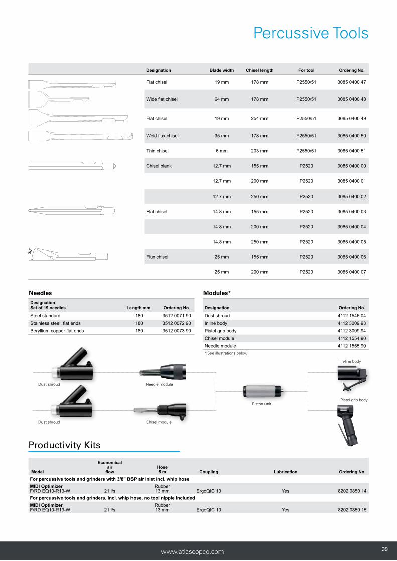
Designation Set of 19 needles Length mm Ordering No.
Steel standard 180 3512 0071 90Stainless steel, flat ends 180 3512 0072 90Beryllium copper flat ends 180 3512 0073 90
Chisel module
In-line body
Dust shroud
Dust shroud
Needle module
Piston unitPistol grip body
Designation Ordering No.
Dust shroud 4112 1546 04Inline body 4112 3009 93Pistol grip body 4112 3009 94Chisel module 4112 1554 90Needle module 4112 1555 90*See illustrations below
Designation Blade width Chisel length For tool Ordering No.
Flat chisel 19 mm 178 mm P2550/51 3085 0400 47
Wide flat chisel 64 mm 178 mm P2550/51 3085 0400 48
Flat chisel 19 mm 254 mm P2550/51 3085 0400 49
Weld flux chisel 35 mm 178 mm P2550/51 3085 0400 50
Thin chisel 6 mm 203 mm P2550/51 3085 0400 51
Chisel blank 12.7 mm 155 mm P2520 3085 0400 00
12.7 mm 200 mm P2520 3085 0400 01
12.7 mm 250 mm P2520 3085 0400 02
Flat chisel 14.8 mm 155 mm P2520 3085 0400 03
14.8 mm 200 mm P2520 3085 0400 04
14.8 mm 250 mm P2520 3085 0400 05
Flux chisel 25 mm 155 mm P2520 3085 0400 06
25 mm 200 mm P2520 3085 0400 07
30˚
32.0 27.0
12.0
11.9
704.3103(3085 0400 48)
32.0 27.0
12.0
11.9
704.3103(3085 0400 49)
32.0 27.0
12.0
11.9
704.3103(3085 0400 47)
32.0 27.0
12.0
11.9
704.3103(3085 0400 50)
Needles Modules*
Model
Economical air
flowHose5 m Coupling Lubrication Ordering No.
For percussive tools and grinders with 3/8" BSP air inlet incl. whip hoseMIDI Optimizer F/RD EQ10-R13-W 21 l/s
Rubber13 mm ErgoQIC 10 Yes 8202 0850 14
For percussive tools and grinders, incl. whip hose, no tool nipple includedMIDI Optimizer F/RD EQ10-R13-W 21 l/s
Rubber13 mm ErgoQIC 10 Yes 8202 0850 15
Productivity Kits
3939www.atlascopco.com

404040 www.atlascopco.com
P2535-H
PRO chipping hammers are available as pistol grip versions for lighter applications.
The bigger D-handle models are suitable for heavy duty applications.
P2530-H P2531-H P2536-H P2539-H
ModelEconomical air
flowHose5 m Coupling Lubrication Ordering No.
For percussive tools and grinders with 3/8" BSP air inlet incl. whip hose
MIDI Optimizer F/RD EQ10-R13-W 21 l/s Rubber 13 mm ErgoQIC 10 Yes 8202 0850 14For percussive tools and grinders, incl. whip hose, no tool nipple included
MIDI Optimizer F/RD EQ10-R13-W 21 l/s Rubber 13 mm ErgoQIC 10 Yes 8202 0850 15
ModelBlows
HzStroke
mm
Energy per blow
JLength
mmWeight
kgBushing
mm
Air cons.
l/s
Rec. hose size mm
Air inlet thread BSP Hex Round Ordering No
P2530-H 60 38 1.3 140 1.1 10.2 5.8 10 1/4'' ● - 8425 0206 15P2530-R 60 38 1.3 140 1.1 10.2 5.8 10 1/4'' - ● 8425 0206 16P2531-H 50 45 4.5 193 1.5 10.2 6.7 10 1/4'' ● - 8425 0206 20P2531-R 50 45 4.5 193 1.5 10.2 6.7 10 1/4'' - ● 8425 0206 21P2535-H 50 45 4.5 273 2.5 12 7 10 1/4'' ● - 8425 0206 30P2535-R 50 45 4.5 273 2.5 14 7 10 1/4'' - ● 8425 0206 31P2536-H 50 25 8.1 301 5 17.5 10 13 3/8'' ● - 8425 0206 35P2539-H 28 102 21.2 425 6.8 17.5 11 13 3/8'' ● - 8425 0206 50
Bushing type
Productivity Kits
Chipping Hammers
Percussive Tools

4141www.atlascopco.com
Other tools
ModelMax free speed
r/minLength
mmWeight
kg
Air cons.
l/s
Rec. hose size
mm
Air inlet thread BSP Ordering No.
P2505 190 175 0.12 0.6 3.2 1/8'' 8425 0102 72
Accessories
Model Ordering No.
P2505 Needle and small parts kit 4081 0068 90
P2505 engraving pen will give a precise result on any hard material, such as aluminum, steel or glass. The needle is easy to change and the tool is small yet durable.
C1050 allows you to cut through material with ease. Due to its geared mechanism the tool will not stall as a conventional air saws commonly do.
ModelStroke per
minute
Stroke length
mm
Blade shank opening
mmLength
mmWeight
kg
Air cons.
l/s
Rec. hose size
mm
Air inlet thread BSP Ordering No.
C1050 10500 5 5 148 0.52 2.2 6.3 1/4'' 8424 1110 50
P2505
C1050
C1050 Ordering No.
Saw Blade 32 teeth 10pcs 4112 3008 45Saw Blade 24 teeth 10pcs 4112 3008 46
Percussive Tools

424242 www.atlascopco.com
Accessories
Designation Width Length For tool Ordering No.
25 mm 250 mm P2520, P2521, P2522
3085 0400 08
Plate cutting chisel 13 mm 208 mm P2530-R, P2531-R
3085 0400 09
13 mm 208 mm P2530-H, P2531-H
3085 0400 10
Double edge plate cutting chisel
19 mm 155 mm P2530-R, P2531-R
3085 0400 11
19 mm 155 mm P2530-H, P2531-H
3085 0400 12
Flat chisel 20 mm 178 mm P2530-R, P2531-R
3085 0400 13
20 mm 178 mm P2530-H, P2531-H
3085 0400 14
Point chisel 3.2 mm 178 mm P2530-R, P2531-R
3085 0400 15
3.2 mm 178 mm P2530-H, P2531-H
3085 0400 16
Rivet cutter 15 mm 150 mm P2530-R, P2531-R
3085 0400 17
15 mm 150 mm P2530-H, P2531-H
3085 0400 18
Chisel blank 12.7 mm 182 mm P2530-R, P2531-R
3085 0400 19
12.7 mm 182 mm P2530-H, P2531-H
3085 0400 20
Spot weld chisel 19 mm 145 mm P2530-R, P2531-R
3085 0400 21
19 mm 145 mm P2530-H, P2531-H
3085 0400 22
15˚
4343www.atlascopco.com
Accessories
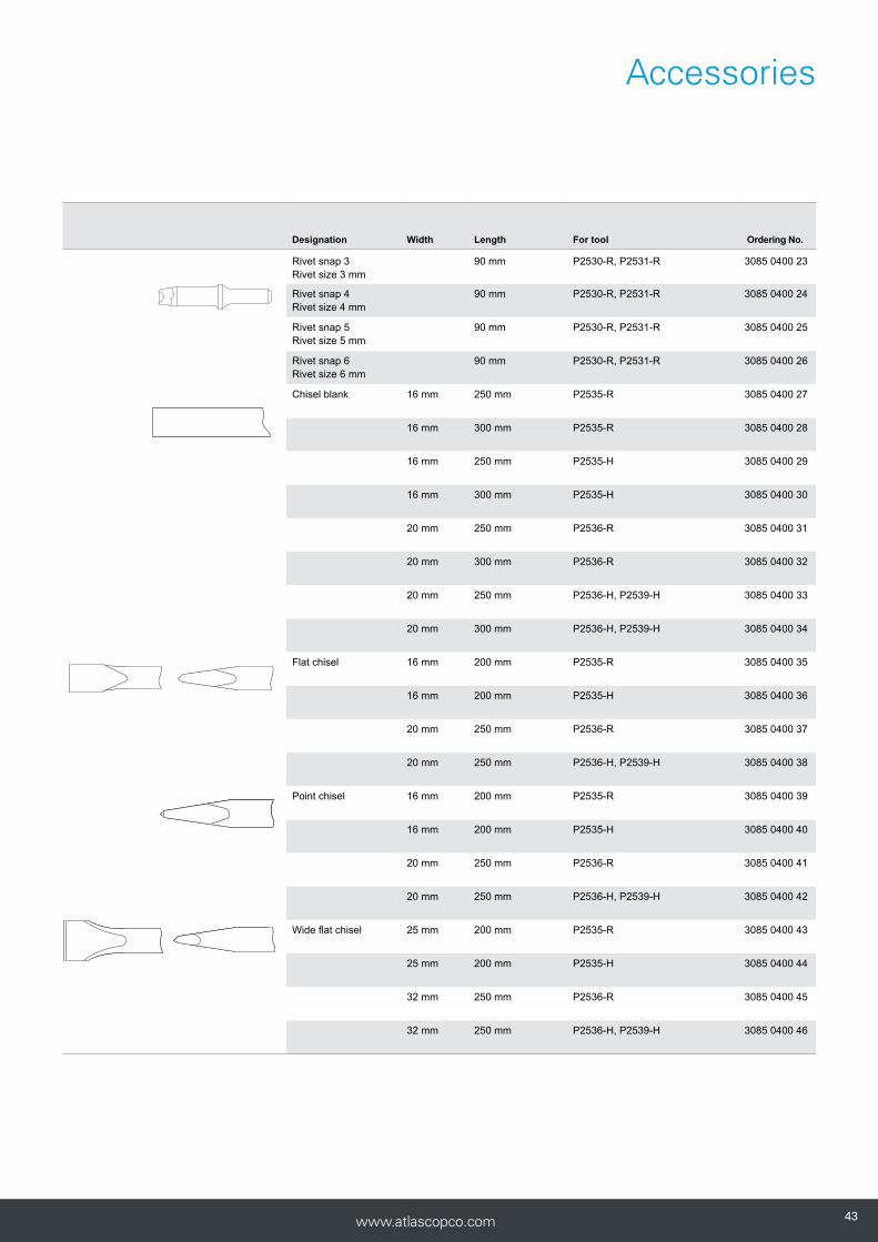
Designation Width Length For tool Ordering No.
Rivet snap 3Rivet size 3 mm
90 mm P2530-R, P2531-R 3085 0400 23
Rivet snap 4Rivet size 4 mm
90 mm P2530-R, P2531-R 3085 0400 24
Rivet snap 5Rivet size 5 mm
90 mm P2530-R, P2531-R 3085 0400 25
Rivet snap 6Rivet size 6 mm
90 mm P2530-R, P2531-R 3085 0400 26
Chisel blank 16 mm 250 mm P2535-R 3085 0400 27
16 mm 300 mm P2535-R 3085 0400 28
16 mm 250 mm P2535-H 3085 0400 29
16 mm 300 mm P2535-H 3085 0400 30
20 mm 250 mm P2536-R 3085 0400 31
20 mm 300 mm P2536-R 3085 0400 32
20 mm 250 mm P2536-H, P2539-H 3085 0400 33
20 mm 300 mm P2536-H, P2539-H 3085 0400 34
Flat chisel 16 mm 200 mm P2535-R 3085 0400 35
16 mm 200 mm P2535-H 3085 0400 36
20 mm 250 mm P2536-R 3085 0400 37
20 mm 250 mm P2536-H, P2539-H 3085 0400 38
Point chisel 16 mm 200 mm P2535-R 3085 0400 39
16 mm 200 mm P2535-H 3085 0400 40
20 mm 250 mm P2536-R 3085 0400 41
20 mm 250 mm P2536-H, P2539-H 3085 0400 42
Wide flat chisel 25 mm 200 mm P2535-R 3085 0400 43
25 mm 200 mm P2535-H 3085 0400 44
32 mm 250 mm P2536-R 3085 0400 45
32 mm 250 mm P2536-H, P2539-H 3085 0400 46

444444 www.atlascopco.com4444
Air preparation units
4545www.atlascopco.com 45
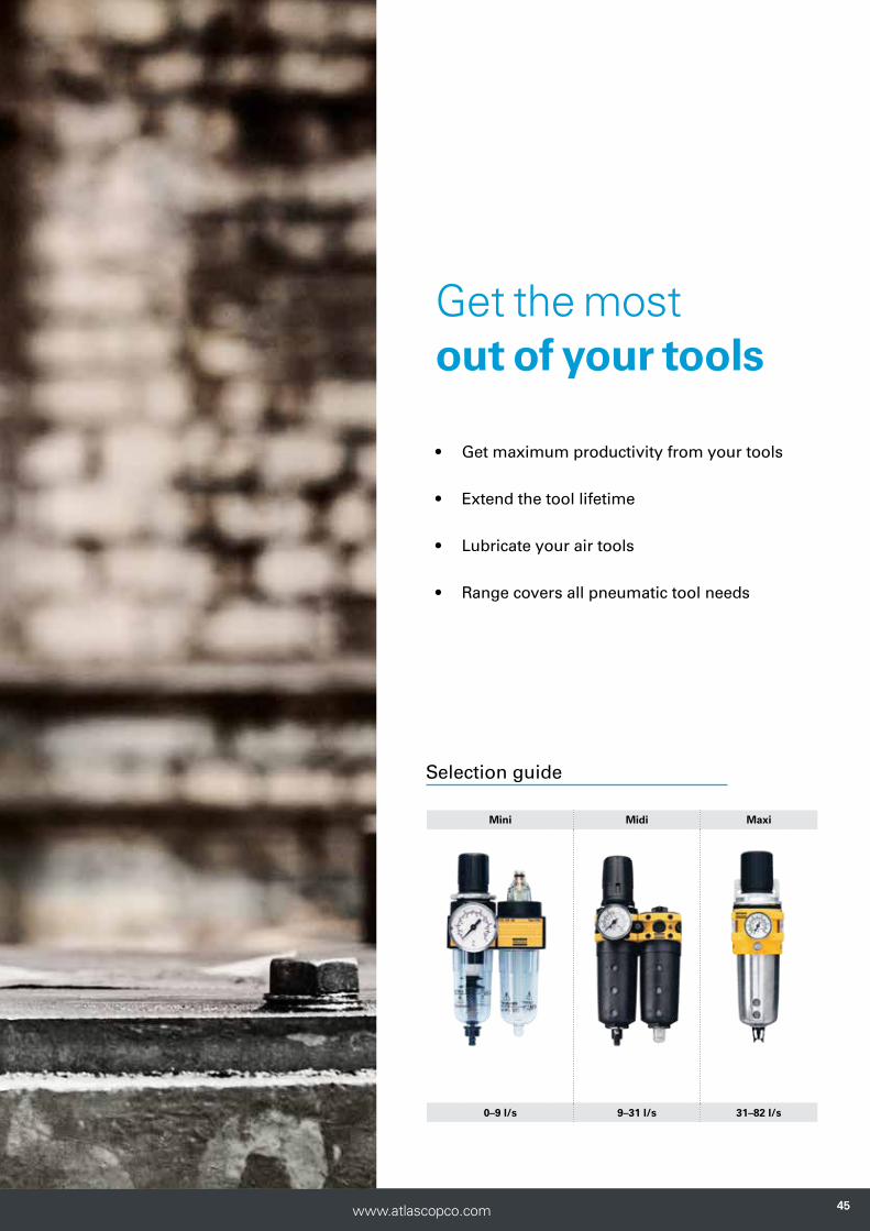
Get the most out of your tools
• Get maximum productivity from your tools
• Extend the tool lifetime
• Lubricate your air tools
• Range covers all pneumatic tool needs
Mini Midi Maxi
0–9 l/s 9–31 l/s 31–82 l/s
Selection guide

464646 www.atlascopco.com
Air Preparation Units
Air preparation unit MINI-K’s main application is to prepare the air for pneumatic components.
MINI-K units have a 1/4” BSP connec-tion thread, a composite housing made of polyamide 66 and the bowls are made of polycarbonate.
• Working temperature 0ºC to +50ºC at 10 bar
• Operating pressure Inlet pressure 0-10 bar Outlet pressure 0.5-8 bar
• Standard filter 30 μm
• Pressure gauge 1/8” BSP
Economical Maximum Filter Max condensate Max oil air flow air flow condensate capacity capacity Weight Model l/s l/s Bowl drainage cm3 cm3 kg Ordering No.
Filters MINI FIL 08K-B 12 30 Polycarbonate Manual 12 - 0.1 9092 0000 01
Regulators MINI REG 08K 10 20 - - - - 0.11 9092 0000 61
Lubricators MINI DIM 08K 9 23 Polycarbonate - - 35 0.09 9092 0000 91
Filter/regulator MINI F/R 08K 12 17 Polycarbonate Manual 12 - 0.12 9092 0001 21
Filter/regulator+lubricator MINI F/RD 08K 9 14 Polycarbonate Manual 12 35 0.32 9092 0001 51
NOTE: Economical air flow: 8 bar inlet pressure, 6.3 bar outlet pressure, 0.2 bar pressure drop.
Maximum air flow: 10 bar inlet pressure, 6.3 bar outlet pressure, 1 bar pressure drop.
All separate units, mounting brackets, as-sembly kits and pressure gauges need to be ordered separately. The MINI K F/RD unit is delivered complete with mounting bracket, assembly kit and pressure gauge.
MINI K
4747www.atlascopco.com
Air Preparation Units
Economical Maximum Filter Max condensate Max oil air flow air flow condensate capacity capacity Weight Model l/s l/s Bowl drainage cm3 cm3 kg Ordering No.
Filters MINI FIL 08B-B 12 24 Polycarbonate Semi/automatic 22 - 0.25 9093 0032 11MINI FIL 08B-C 12 24 Polycarbonate Manual 22 0.25 9093 0032 41MINI FIL 08B-D 13 24 Metal Manual 22 0.25 9093 0032 71
Regulators MINI REG 08B 9 47.5 - - - - 0.30 9093 0033 01MINI REG 08B-LP 9 47.5 - - - - 0.30 9093 0073 21MINI REG 08P 8 47.5 - - - - 0.30 9093 0000 31
Lubricators MINI DIM 08B 12 23 Polycarbonate - - 45 0.25 9093 0033 31MINI DIM 08B-D 12 23 Metal - - 45 0.25 9093 0033 61
Filter/regulator MINI F/R 08B-B 9 38 Polycarbonate Semi/automatic 22 - 0.35 9093 0033 91MINI F/R 08B-C 9 38 Polycarbonate Manual 22 - 0.35 9093 0034 21
Filter/regulator+lubricator MINI F/RD 08B-B 9 14.8 Polycarbonate Semi/automatic 22 45 0.75 9093 0034 51MINI F/RD 08B-C 9 14.8 Polycarbonate Manual 22 45 0.75 9093 0034 81
Filter+regulator+lubricator MINI FRD 08B-B 9 13.8 Polycarbonate Semi/automatic 22 45 0.95 9093 0062 11MINI FRD 08B-C 9 13.8 Polycarbonate Manual 22 45 0.95 9093 0062 41
NOTE: Economical air flow: 8 bar inlet pressure, 6.3 bar outlet pressure, 0.2 bar pressure drop.
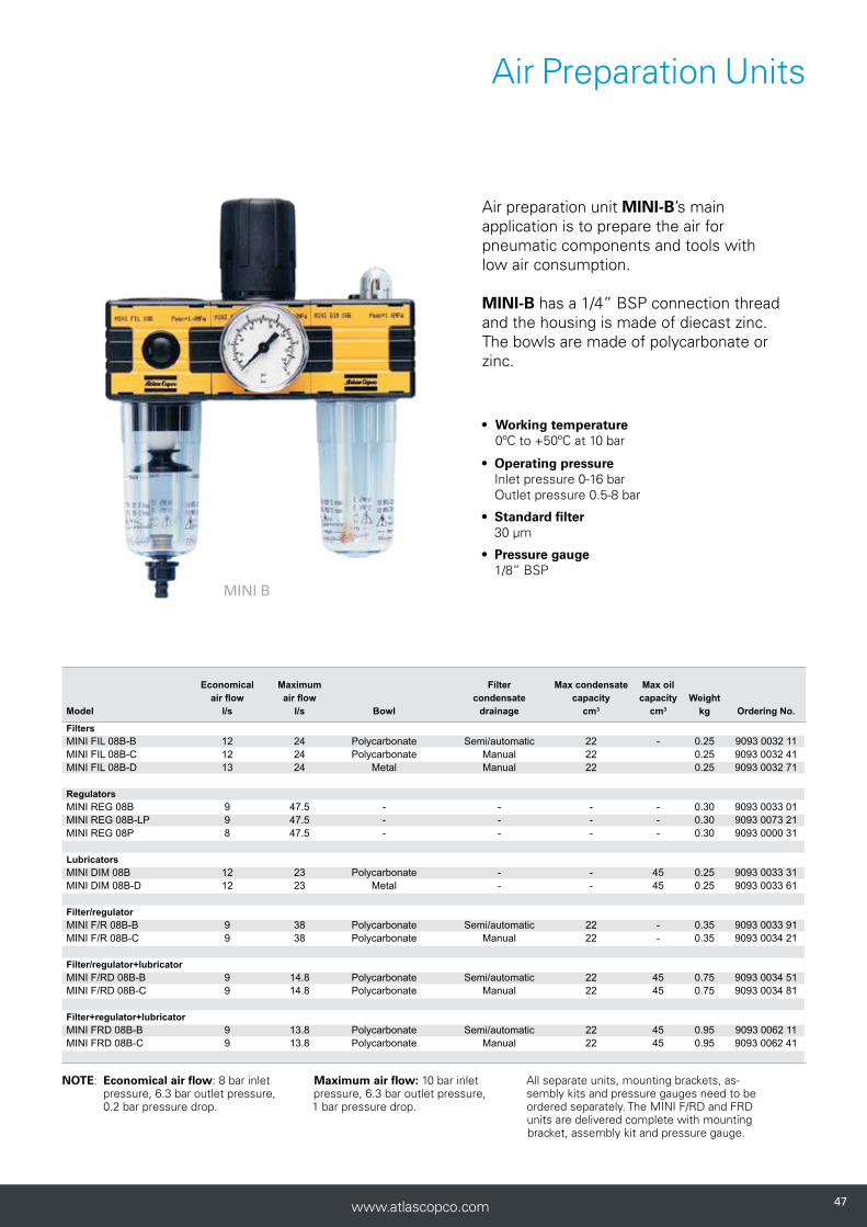
Air preparation unit MINI-B’s main application is to prepare the air for pneumatic components and tools with low air consumption.
MINI-B has a 1/4” BSP connection thread and the housing is made of diecast zinc. The bowls are made of polycarbonate or zinc.
• Working temperature 0ºC to +50ºC at 10 bar
• Operating pressure Inlet pressure 0-16 bar Outlet pressure 0.5-8 bar
• Standard filter 30 μm
• Pressure gauge 1/8” BSP
MINI B
All separate units, mounting brackets, as-sembly kits and pressure gauges need to be ordered separately. The MINI F/RD and FRD units are delivered complete with mounting bracket, assembly kit and pressure gauge.
Maximum air flow: 10 bar inlet pressure, 6.3 bar outlet pressure, 1 bar pressure drop.
484848 www.atlascopco.com
Economical Maximum Filter Max condensate Max oil air flow air flow condensate capacity capacity Weight Model l/s l/s Bowl drainage cm3 cm3 kg Ordering No.
Filters MIDI Optimizer FIL A - 117 Polymer, plastic insert Automatic 60 - 0.3 9093 0021 01MIDI Optimizer FIL M/S - 117 Polymer, plastic insert Manual/semi auto 60 - 0.3 9093 0021 02
Regulators MIDI Optimizer REG - 97 - - - - 0.35 9093 0021 05MIDI Optimizer REG LP - 97 - - - - 0.35 9093 0021 06MIDI Optimizer REG HP - 97 - - - - 0.35 9093 0021 30
Lubricators MIDI Optimizer DIM 31 120 Polymer, plastic insert - - 90 0.3 9093 0021 10MIDI Optimizer DIM EP 31 120 Polymer, plastic insert - - 90 0.3 9093 0021 33
Filter/regulator MIDI Optimizer F/R A - 90 Polymer, plastic insert Automatic 60 - 0.5 9093 0021 12MIDI Optimizer F/R M/S - 90 Polymer, plastic insert Manual/semi auto 60 - 0.5 9093 0021 13MIDI Optimizer F/R M/S HP - 90 Polymer, plastic insert Manual/semi auto 60 - 0.5 9093 0021 31MIDI Optimizer F/R HP A - 90 Polymer, plastic insert Automatic 60 - 0.5 9093 0021 32
Filter/regulator+lubricator MIDI Optimizer F/RD A 31 55 Polymer, plastic insert Automatic 60 90 1.0 9093 0021 16MIDI Optimizer F/RD M/S 31 55 Polymer, plastic insert Manual/semi auto 60 90 1.0 9093 0021 17MIDI Optimizer F/RD A EP 31 55 Polymer, plastic insert Automatic 60 90 1.0 9093 0021 35MIDI Optimizer F/RD M/S EP 31 55 Polymer, plastic insert Manual/semi auto 60 90 1.0 9093 0021 36
Filter+regulator+lubricator MIDI Optimizer FRD A 31 55 Polymer, plastic insert Automatic 60 90 1.1 9093 0021 24MIDI Optimizer FRD M/S 31 55 Polymer, plastic insert Manual/semi auto 60 90 1.1 9093 0021 25
NOTE: Economical air flow: 8 bar inlet pressure, 6.3 bar outlet pressure, 0.2 bar pressure drop. Maximum air flow: 10 bar inlet pressure, 6.3 bar outlet pressure, 1 bar pressure drop.
All separate units, mounting brackets, assembly kits and pressure gauges need to be ordered separately. The MIDI Optimizer F/RD and FRD units are deliv-ered complete with mounting bracket, assembly kit and pressure gauge.
EP For impact and pulse tools A Automatic M/S Manual/semi automatic HP High pressure regulator LP Lockable regulator
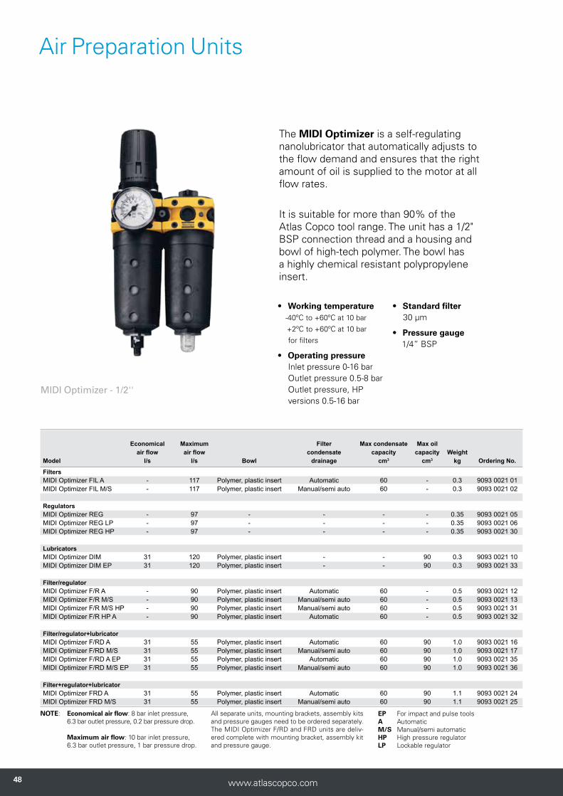
MIDI Optimizer - 1/2''
The MIDI Optimizer is a self-regulating nanolubricator that automatically adjusts to the flow demand and ensures that the right amount of oil is supplied to the motor at all flow rates.
It is suitable for more than 90% of the Atlas Copco tool range. The unit has a 1/2" BSP connection thread and a housing and bowl of high-tech polymer. The bowl has a highly chemical resistant polypropylene insert.
• Working temperature -40ºC to +60ºC at 10 bar +2ºC to +60ºC at 10 bar for filters
• Operating pressure Inlet pressure 0-16 bar Outlet pressure 0.5-8 bar Outlet pressure, HP versions 0.5-16 bar
• Standard filter 30 μm
• Pressure gauge 1/4” BSP
Air Preparation Units
4949www.atlascopco.com
Economical Maximum Filter Max condensate Max oil air flow air flow condensate capacity capacity Weight Model l/s l/s Bowl drainage cm3 cm3 kg Ordering No.
Filters MIDI Optimizer 3/4" FIL A - 117 Polymer, plastic insert Automatic 60 - 0.3 9093 0021 40MIDI Optimizer 3/4" FIL M/S - 117 Polymer, plastic insert Manual/semi auto 60 - 0.3 9093 0021 41 Regulators MIDI Optimizer 3/4" REG - 97 - - - - 0.35 9093 0021 42MIDI Optimizer 3/4" REG LP - 97 - - - - 0.35 9093 0021 43MIDI Optimizer 3/4" REG HP - 97 - - - - 0.35 9093 0021 44 Lubricators MIDI Optimizer 3/4" DIM 31 120 Polymer, plastic insert - - 90 0.3 9093 0021 45MIDI Optimizer 3/4" DIM EP 31 120 Polymer, plastic insert - - 90 0.3 9093 0021 54 Filter/regulator MIDI Optimizer 3/4" F/R A - 90 Polymer, plastic insert Automatic 60 - 0.5 9093 0021 46MIDI Optimizer 3/4" F/R M/S - 90 Polymer, plastic insert Manual/semi auto 60 - 0.5 9093 0021 47MIDI Optimizer 3/4" F/R M/S HP - 90 Polymer, plastic insert Manual/semi auto 60 - 0.5 9093 0021 48MIDI Optimizer F/R 3/4" HP A - 90 Polymer, plastic insert Automatic 60 - 0.5 9093 0021 49 Filter/regulator+lubricator MIDI Optimizer 3/4" F/RD A 31 55 Polymer, plastic insert Automatic 60 90 1.0 9093 0021 50MIDI Optimizer 3/4" F/RD A EP 31 55 Polymer, plastic insert Automatic 60 90 1.0 9093 0021 55MIDI Optimizer 3/4" F/RD M/S 31 55 Polymer, plastic insert Manual/semi auto 60 90 1.0 9093 0021 56MIDI Optimizer 3/4" F/RD M/S EP 31 55 Polymer, plastic insert Manual/semi auto 60 90 1.0 9093 0021 51 Filter+regulator+lubricator MIDI Optimizer 3/4" FRD A 31 55 Polymer, plastic insert Automatic 60 90 1.1 9093 0021 52MIDI Optimizer 3/4" FRD M/S 31 55 Polymer, plastic insert Manual/semi auto 60 90 1.1 9093 0021 53
NOTE: Economical air flow: 8 bar inlet pressure, 6.3 bar outlet pressure, 0.2 bar pressure drop. Maximum air flow: 10 bar inlet pressure, 6.3 bar outlet pressure, 1 bar pressure drop.
All separate units, mounting brackets, assembly kits and pressure gauges need to be ordered separately. The MIDI Optimizer F/RD and FRD units are deliv-ered complete with mounting bracket, assembly kit and pressure gauge.
EP For impact and pulse tools A Automatic M/S Manual/semi automatic HP High pressure regulator LP Lockable regulator
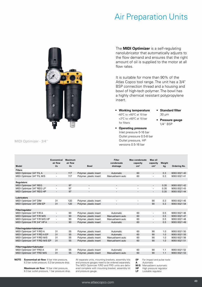
MIDI Optimizer - 3/4''
The MIDI Optimizer is a self-regulating nanolubricator that automatically adjusts to the flow demand and ensures that the right amount of oil is supplied to the motor at all flow rates.
It is suitable for more than 90% of the Atlas Copco tool range. The unit has a 3/4" BSP connection thread and a housing and bowl of high-tech polymer. The bowl has a highly chemical resistant polypropylene insert.
• Working temperature -40ºC to +60ºC at 10 bar +2ºC to +60ºC at 10 bar for filters
• Operating pressure Inlet pressure 0-16 bar Outlet pressure 0.5-8 bar Outlet pressure, HP versions 0.5-16 bar
• Standard filter 30 μm
• Pressure gauge 1/4” BSP
Air Preparation Units
505050 www.atlascopco.com
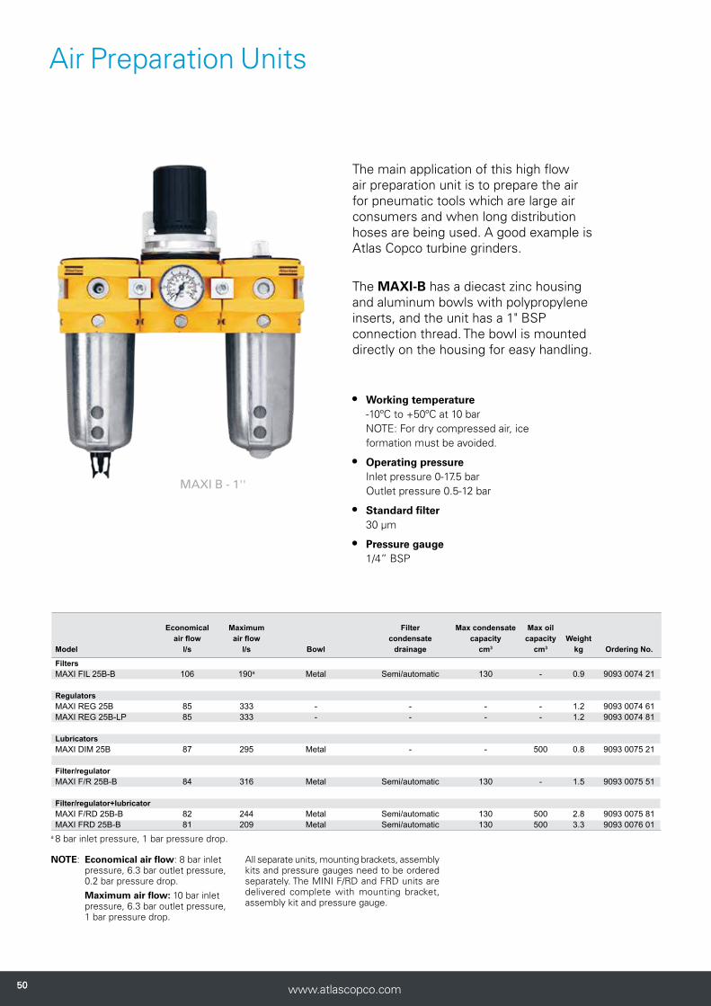
The main application of this high flow air preparation unit is to prepare the air for pneumatic tools which are large air consumers and when long distribution hoses are being used. A good example is Atlas Copco turbine grinders.
The MAXI-B has a diecast zinc housing and aluminum bowls with polypropylene inserts, and the unit has a 1" BSP connection thread. The bowl is mounted directly on the housing for easy handling.
• Working temperature -10ºC to +50ºC at 10 bar NOTE: For dry compressed air, ice formation must be avoided.
• Operating pressure Inlet pressure 0-17.5 bar Outlet pressure 0.5-12 bar
• Standard filter 30 μm
• Pressure gauge 1/4” BSP
a 8 bar inlet pressure, 1 bar pressure drop.
Economical Maximum Filter Max condensate Max oil air flow air flow condensate capacity capacity Weight Model l/s l/s Bowl drainage cm3 cm3 kg Ordering No.
Filters MAXI FIL 25B-B 106 190a Metal Semi/automatic 130 - 0.9 9093 0074 21
Regulators MAXI REG 25B 85 333 - - - - 1.2 9093 0074 61MAXI REG 25B-LP 85 333 - - - - 1.2 9093 0074 81
Lubricators MAXI DIM 25B 87 295 Metal - - 500 0.8 9093 0075 21
Filter/regulator MAXI F/R 25B-B 84 316 Metal Semi/automatic 130 - 1.5 9093 0075 51
Filter/regulator+lubricator MAXI F/RD 25B-B 82 244 Metal Semi/automatic 130 500 2.8 9093 0075 81MAXI FRD 25B-B 81 209 Metal Semi/automatic 130 500 3.3 9093 0076 01
NOTE: Economical air flow: 8 bar inlet pressure, 6.3 bar outlet pressure, 0.2 bar pressure drop.
Maximum air flow: 10 bar inlet pressure, 6.3 bar outlet pressure, 1 bar pressure drop.
All separate units, mounting brackets, assembly kits and pressure gauges need to be ordered separately. The MINI F/RD and FRD units are delivered complete with mounting bracket, assembly kit and pressure gauge.
MAXI B - 1''
Air Preparation Units

5151www.atlascopco.com
Model MINI-K MINI-B
MIDI OPTIMIZER
1/2"
MIDI OPTIMIZER
3/4" MAXI-B
Mounting bracket kit a 9090 1902 00 9092 0063 01 9093 0022 01 9093 0022 01 9093 0076 15Assembly kit a 9090 1901 90 9092 0062 71 9093 0022 02 9093 0022 02 9093 0076 31Filter (FIL) accessories (30 μm filter element is incl with all filters)30 μm filter element 9090 1898 00 9092 0063 31 9093 0023 04 9093 0023 04 9093 0076 615 μm filter element 9092 0063 61 9093 0023 05 9093 0023 05 9093 0076 71Bowl guard 9092 0063 91Regulator (REG) accessories b
Pressure gauge, 0-10 bar, Ø 40 mm 9090 1907 00 9090 1907 00Pressure gauge, 0-10 bar, Ø 50 mm 9090 1172 00 9090 2052 00 9090 2052 00Pressure gauge, 0-10 bar, Metal housing 9090 2052 01 9090 2052 01Pressure gauge, 0-16 bar, Ø 49 mm 9090 0239 00 9090 0239 00 9090 0239 00Pressure gauge, 0-16 bar, Ø 50 mm 9090 1657 00Panel mounting pressure gauge, 0-10 bar, Ø 50 mm 9090 1173 00 9090 1173 00 9090 1173 00Panel mounting pressure gauge, 0-16 bar, Ø 63 mm 9093 0076 43Key lock for regulator -LP 9092 0074 11 9092 0074 11 9092 0074 11 9092 0074 11Lubricator (DIM) accessoriesAir distribution block kit 9090 1900 90 9092 0064 51 9093 0022 03 9093 0022 04 9093 0076 41Bowl guard 9092 0063 91Glass sight dome 9090 1121 00Oil reduction plate 9093 0022 06 9093 0022 06
a Are included in combination units (FD, FTD, F/RD and FRD). Mounting bracket kits and assembly kits have to be ordered separately for separate units. b Pressure gauge 0-10 bar is included in the combination units (F/RD and FRD). Pressure gauge has to be ordered separately for separate units.
Model Ordering No.Optimizer 0.5 liter 9090 0000 02Optimizer 1 liter 9090 0000 04Optimizer 4 liter 9090 0000 06
Atlas Copco Optimizer air tool oil is a white, oil based lubricant for pneumatic tools. It has excellent antiwear properties and contains additives preventing oxi-dation and foaming. Optimizer air tool oil provides a better working environment, compared to conventional mist lubrication oils and is recommended when stringent demands are placed on the working environment. Safety data sheets (MSDS/SDS) available online.
• Temperature range -25ºC to +70ºC
• Density at 15ºC 869 kg/m3
• Viscosity at 40ºC 22 mm2/s
• Pour point -48ºC
• Flash point COC >170ºC
Optimizer - Air Tool Oil
Model Ordering No.
FRL-Stand - suits all models 9090 2101 00
FRL-Stand - Midi BSP * 9090 3030 06
FRL-Stand - Maxi BSP * 9090 3030 04
Hose kits to fit FRL-Stand (Midi and Maxi)
TURBO 13 - EQ10 - 5M -EU 8202 1181 81
TURBO 16 - EQ15E - 5M - EU 8202 1181 82
TURBO 20 - 8202 1181 83
FRL-stand
* Hose kit not included in FRL stand
Optimizer - Air Tool OilFRL-Stand - suits all models
Air Preparation Units
525252 www.atlascopco.com
Connectors and Couplings

5353www.atlascopco.com
• Get the best air flow
• Wide range of standard couplings
• Easy-to-use safety couplings
• Suitable for all types of pneumatic tools
Be fast, quick and productive

545454 www.atlascopco.com
MultiFlex Swivel
MultiFlex Swivel is a multi-directional connector.
Once the tool is connected the hose will stay in the ideal position however much the operator and the tool move around. The MultiFlex bends and rotates 360º in all directions while the hose stays straight.
Connectors and Couplings
ErgoQIC
The ErgoQIC coupling is a ball valve coupling with a safety feature offering a higher flow than ordinary coupling systems. The ErgoQIC is a strong and durable full flow quick coupling with no air restriction inside the coupling. It is suitable for assembly tools, drills and grinders. Upgrading any air system with ErgoQIC will give the benefits of productivity and energy efficiency. ErgoQIC is designed to minimize the risk of sudden com-ponent separation and sound bang. The safety features are according to EN 983 and ISO 4414. It is made of hardened steel.
The ErgoQIC disconnects in two steps; first you push in and bend slowly – the pressurized air hose will then vent, and as a second step you can disconnect without risk of harming the operator.
Claw
CLAW couplings are made from dropforged, hardened steel which can withstand rough treatment and ensures a long life even under difficult conditions. The coupling head is the same for all hose sizes, which can therefore be freely combined.
The recommended maximum working pres-sure is 10 bar.
SmartQIC
SMARTQIC is the latest gen-eration of pneumatic safety couplings and nipples. The couplings offers high flow and low pressure drop with innovative safety features. The design has a unique safety venting feature when disconnecting, thus minimizing risk of injury to the operator.
Durable and tough, the couplings are made out of zinc-plated steel/brass material and the entire product range complies with safety standards ISO 4414 and EN 983. SMARTQIC couplings also complies with OSHA 1910.95.
Suitable for many types of applications and pneumatic tools; such as screwdrivers, assembly tools, drills and grinders.
5555www.atlascopco.com
Connectors and Couplings
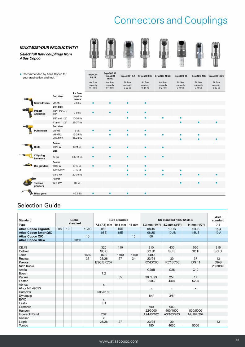
Selection Guide
Standard Globalstandard
Euro standard US standard / ISO 6150-B Asia
standardType 7.6 (7.4) mm 10.4 mm 15 mm 5.3 mm (1/4") 8.2 mm (3/8") 11 mm (1/2") 7.5Atlas Copco ErgoQIC 08 10 10AC 08E 15E 08US 10US 15US 10 AAtlas Copco SmartQIC 08E 15E 08US 10US 15US 10 AAtlas Copco QIC 10 15 08Atlas Copco Claw Claw
CEJN 320 410 310 430 550 315Oetiker SC C SC B1 SC E SC H SC DTema 1650 1600 1700 1750 1400Rectus 33 25/26 27 34 23/24 30 37 13Prevost ESC/ERC07 IRC/ISC06 IRC/ISC08 ISG 11 ORGNitto Kohki 20/30/40Amflo C20B C26 C10Bosch 7.2Parker 55 30 / B23 25F 17Foster 3003 4404 5205Abnox xAfnor NF 49053 x x xCamozzi 508/5180Dynaquip 1/4" 3/8"EWO xFesto KDGromelle 600 900Hansen 22/3000 400/4000 500/5000Ingersoll Rand 7S7 A2/MS/102 A3/103/203 A4/104/204Kaeser xLegris 25/26 27 23/24 30 13Tomco 180 4000 5000
● ● ● ●
● ● ● ●
● ● ● ●● ● ●
● ● ● ●● ● ● ● ● ●
● ● ●
● ● ● ● ●
● ● ● ● ●
● ● ● ●● ● ● ●● ● ● ● ● ●
● ● ●
● ● ● ●
MAXIMIZE YOUR PRODUCTIVITY!
Select full flow couplings from Atlas Copco
● Recommended by Atlas Copco for your application and tool.
ErgoQIC 08US
ErgoQIC 08 ErgoQIC
10AC ErgoQIC 10 A ErgoQIC 08E ErgoQIC 10US ErgoQIC 10 ErgoQIC 15E ErgoQIC 15US
Air flow capacity0-11 l/s
Air flow capacity0-18 l/s
Air flow capacity0-22 l/s
Air flow capacity0-24 l/s
Air flow capacity0-27 l/s
Air flow capacity0-40 l/s
Air flow capacity0-49 l/s
Air flow capacity0-52 l/s
Bolt sizeAir flow require-ments
Screwdrivers M2-M6 2-8 l/s
Bolt sizeImpact wrenches
1/4" HEX and 3/8" 2-9 l/s
3/8" and 1/2" 10-20 l/s1" and 1 1/2" 28-37 l/s
Bolt size
Pulse tools M4-M5 9 l/sM6-M12 15-25 l/s
M14-M20 32-49 l/s
PowerDrills <820 W 8-21 l/s
Size
Chipping hammers <7 kg 6.5-14 l/s
PowerDie grinders <500 W 3-10 l/s
500-900 W 7-19 l/s
0.9-2 kW 20-35 l/s
PowerTurbine grinders
<2.5 kW 32 l/s
Blow guns 4-7.5 l/s
565656 www.atlascopco.com
Connectors and Couplings
1008
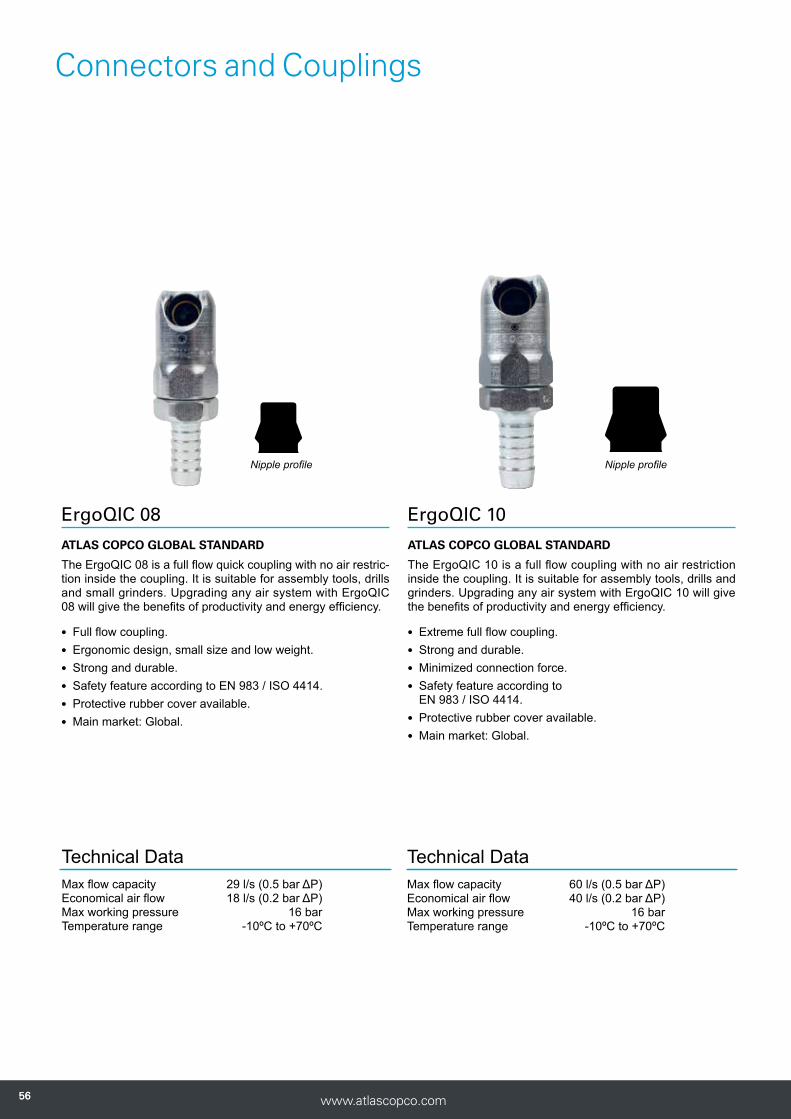
ErgoQIC 08
ATLAS COPCO GLOBAL STANDARD
The ErgoQIC 08 is a full flow quick coupling with no air restric-tion inside the coupling. It is suitable for assembly tools, drills and small grinders. Upgrading any air system with ErgoQIC 08 will give the benefits of productivity and energy efficiency.
lFull flow coupling.lErgonomic design, small size and low weight.lStrong and durable.lSafety feature according to EN 983 / ISO 4414.lProtective rubber cover available.lMain market: Global.
Technical DataMax flow capacity 29 l/s (0.5 bar ΔP)Economical air flow 18 l/s (0.2 bar ΔP)Max working pressure 16 barTemperature range -10ºC to +70ºC
Nipple profile
ErgoQIC 10
ATLAS COPCO GLOBAL STANDARD
The ErgoQIC 10 is a full flow coupling with no air restriction inside the coupling. It is suitable for assembly tools, drills and grinders. Upgrading any air system with ErgoQIC 10 will give the benefits of productivity and energy efficiency.
lExtreme full flow coupling.lStrong and durable.lMinimized connection force.lSafety feature according to
EN 983 / ISO 4414.lProtective rubber cover available.lMain market: Global.
Technical DataMax flow capacity 60 l/s (0.5 bar ΔP)Economical air flow 40 l/s (0.2 bar ΔP)Max working pressure 16 barTemperature range -10ºC to +70ºC
Nipple profile

5757www.atlascopco.com
Connectors and Couplings
ERGOQIC 08 AND ERGONIP 08, 18 L/S (recommended air flow at 6.3 bar pressure)
Connection Coupling Size Connection Nipple Sizetype ErgoQIC 08 Ordering No. mm in type ErgoNIP 08 Ordering No. mm in
H – Hose H06 8202 1110 04 6.3 1/4 H – Hose H05 8202 1210 33 5 3/16 H08 8202 1110 12 8 5/16 H06 8202 1210 37 6.3 1/4 H10 8202 1110 38 10 3/8 H08 8202 1210 45 8 5/16 H13 8202 1110 40 12.5 1/2 H10 8202 1210 52 10 3/8 H13 8202 1210 54 12.5 1/2
M – Male M08 8202 1110 61 1/4 BSP SH – Safety Hose a SH06 8202 1210 39 6.3 1/4 M10 8202 1110 79 3/8 BSP SH08 8202 1210 47 8 5/16 M15 8202 1110 87 1/2 BSP SH10 8202 1210 50 10 3/8 SH13 8202 1210 55 12.5 1/2
F – Female F08 8202 1110 90 1/4 BSP M – Male M06 8202 1210 03 1/8 BSP F10 8202 1110 95 3/8 BSP M08 8202 1210 11 1/4 BSP M10 8202 1210 29 3/8 BSP M15 8202 1210 31 1/2 BSP
Protective cover 9090 1940 00 F – Female F08 8202 1210 60 1/4 BSP F10 8202 1210 62 3/8 BSP
a For joining hoses longer than 3 meters.
ERGOQIC 10 AND ERGONIP 10, 40 L/S (recommended air flow at 6.3 bar pressure)
Connection Coupling Size Connection Nipple Sizetype ErgoQIC 10 Ordering No. mm in type ErgoNIP 10 Ordering No. mm in
H – Hose H06 8202 1120 30 6.3 1/4 H – Hose H06 8202 1220 35 6.3 1/4 H08 8202 1120 40 8 5/16 H08 8202 1220 43 8 5/16 H10 8202 1120 02 10 3/8 H10 8202 1220 50 10 3/8 H13 8202 1120 10 12.5 1/2 H13 8202 1220 68 12.5 1/2 H16 8202 1120 50 16 5/8 H16 8202 1220 76 16 5/8 H20 8202 1120 60 19 3/4 H20 8202 1220 77 19 3/4
M – Male M08 8202 1120 85 1/4 BSP SH – Safety Hose a SH06 8202 1220 37 6.3 1/4 M10 8202 1120 93 3/8 BSP SH08 8202 1220 45 8 5/16 M15 8202 1120 97 1/2 BSP SH10 8202 1220 52 10 3/8 M20 8202 1120 98 3/4 BSP SH13 8202 1220 70 12.5 1/2 M25 8202 1120 99 1 BSP SH16 8202 1220 74 16 5/8 SH20 8202 1220 75 19 3/4
F – Female F08 8202 1121 00 1/4 BSP M – Male M08 8202 1220 01 1/4 BSP F10 8202 1121 05 3/8 BSP M10 8202 1220 19 3/8 BSP F15 8202 1121 10 1/2 BSP M15 8202 1220 27 1/2 BSP
Protective cover 9090 1931 00 F – Female F08 8202 1220 84 1/4 BSP F10 8202 1220 86 3/8 BSP F15 8202 1220 88 1/2 BSP
a For joining hoses longer than 3 meters.
585858 www.atlascopco.com
Connectors and Couplings
08 08
Nipple profile
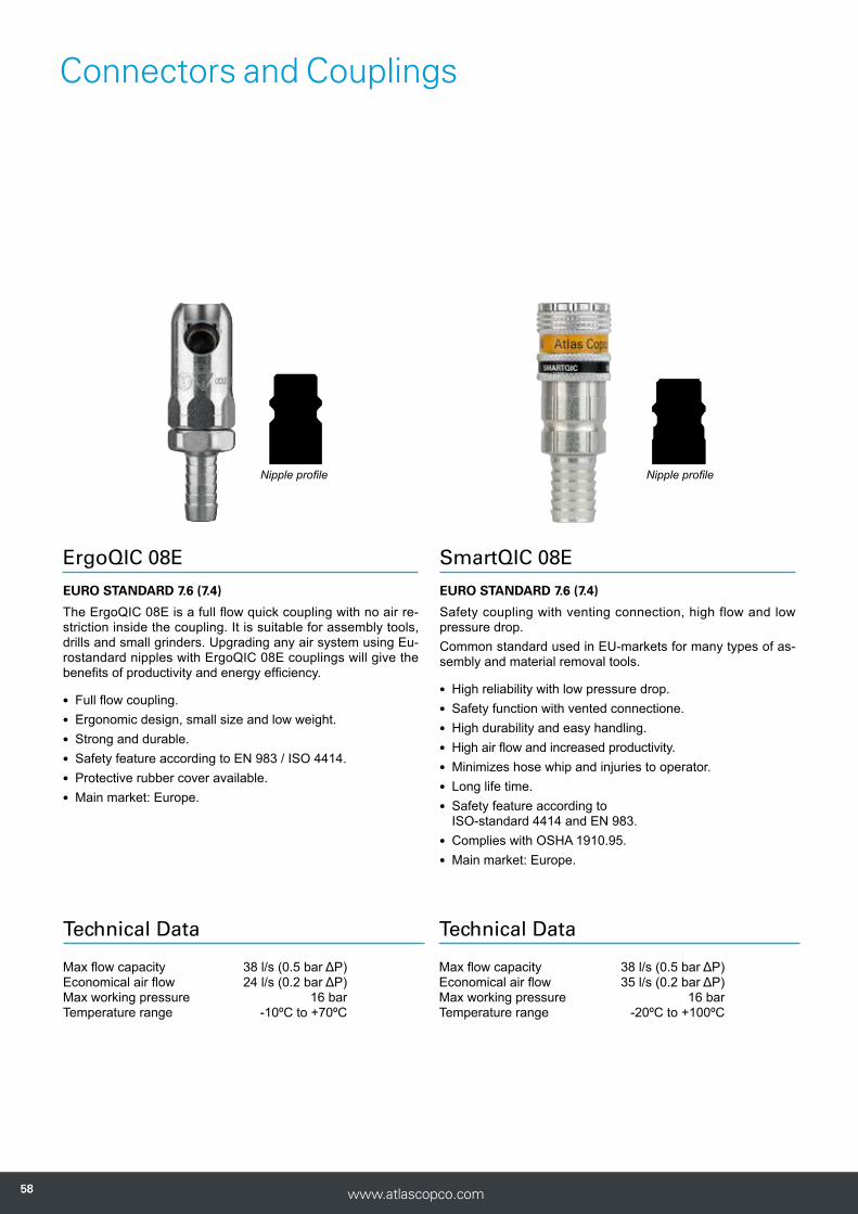
ErgoQIC 08E
EURO STANDARD 7.6 (7.4)
The ErgoQIC 08E is a full flow quick coupling with no air re-striction inside the coupling. It is suitable for assembly tools, drills and small grinders. Upgrading any air system using Eu-rostandard nipples with ErgoQIC 08E couplings will give the benefits of productivity and energy efficiency.
lFull flow coupling.lErgonomic design, small size and low weight.lStrong and durable.lSafety feature according to EN 983 / ISO 4414.lProtective rubber cover available.lMain market: Europe.
Technical Data
Max flow capacity 38 l/s (0.5 bar ΔP)Economical air flow 24 l/s (0.2 bar ΔP)Max working pressure 16 barTemperature range -10ºC to +70ºC
SmartQIC 08E
EURO STANDARD 7.6 (7.4)
Safety coupling with venting connection, high flow and low pressure drop. Common standard used in EU-markets for many types of as-sembly and material removal tools.
lHigh reliability with low pressure drop.lSafety function with vented connectione.lHigh durability and easy handling.lHigh air flow and increased productivity.lMinimizes hose whip and injuries to operator.lLong life time.lSafety feature according to
ISO-standard 4414 and EN 983. lComplies with OSHA 1910.95.lMain market: Europe.
Technical Data
Max flow capacity 38 l/s (0.5 bar ΔP)Economical air flow 35 l/s (0.2 bar ΔP)Max working pressure 16 barTemperature range -20ºC to +100ºC
Nipple profile

5959www.atlascopco.com
Connectors and Couplings
ERGOQIC 08E AND NIP EU 7.6, 24 L/S (recommended air flow at 6.3 bar pressure)
Connection Coupling Size Connection Nipple Sizetype ErgoQIC 08E Ordering No. mm in type NIP EU 7.6 Ordering No. mm in
H – Hose H06 8202 1106 00 6.3 1/4 H – Hose H05 8202 1204 00 5 3/16 H08 8202 1106 01 8 5/16 H06 8202 1204 05 6.3 1/4 H10 8202 1106 02 10 3/8 H08 8202 1204 10 8 5/16 H13 8202 1106 03 12.5 1/2 H10 8202 1204 15 10 3/8 H13 8202 1204 20 12.5 1/2
M – Male thread M08 8202 1106 04 1/4 BSP M – Male thread M06 8202 1204 25 1/8 BSP M10 8202 1106 05 3/8 BSP M08 8202 1204 30 1/4 BSP M15 8202 1106 06 1/2 BSP M10 8202 1204 35 3/8 BSP
F – Female F08 8202 1106 07 1/4 BSP MT – Male taper thread MT08 8202 1204 40 1/4 BSPT F10 8202 1106 08 3/8 BSP MT10 8202 1204 45 3/8 BSPT F15 8202 1106 09 1/2 BSP MT15 8202 1204 50 1/2 BSPT
Protective cover a 9090 1940 01 F – Female F08 8202 1204 55 1/4 BSP F10 8202 1204 60 3/8 BSP
a Protect your work piece with a protective rubber cover for the ErgoQIC coupling.
SMARTQIC 08E AND NIP 08E, EU 7.6 35 L/S (recommended air flow at 6.3 bar pressure)
Connection Coupling Size Connection Nipple Sizetype SmartQIC-08E Ordering No. mm in type NIP-08E Ordering No. mm in
H – Hose H08 4221 0010 00 8 5/16 H – Hose H06 4221 0011 00 6.3 1/4 H10 4221 0010 01 10 3/8 H08 4221 0011 01 8 5/16 H13 4221 0010 02 13 1/2 H10 4221 0011 02 10 3/8 H13 4221 0011 03 13 5/16
M – Male M06 4221 0010 03 1/4 BSPT M – Male M06 4221 0011 04 1/4 BSP M10 4221 0010 04 3/8 BSPT M10 4221 0011 05 3/8 BSP M15 4221 0010 05 1/2 BSPT M15 4221 0011 06 1/2 BSP
F – Female F06 4221 0010 06 1/4 BSP F – Female F06 4221 0011 07 1/4 BSP F10 4221 0010 07 3/8 BSP F10 4221 0011 08 3/8 BSP F15 4221 0010 08 1/2 BSP F15 4221 0011 09 1/2 BSP

606060 www.atlascopco.com
Connectors and Couplings
15 15
15
ErgoQIC 15E
EURO STANDARD 10.4
The ErgoQIC 15E is a full flow coupling with no air restriction inside the coupling suitable for large air consuming assembly tools, drills and grinders. Upgrading any air system with Er-goQIC 15E will give the benefit of productivity and energy ef-ficiency.
lExtreme full flow coupling.lStrong and durable.lMinimized connection force.lSafety feature according to EN 983 / ISO 4414.lMain market: Europe.
Nipple profile
Technical Data
Max flow capacity 76 l/s (0.5 bar ΔP)Economical air flow 49 l/s (0.2 bar ΔP)Max working pressure 16 barTemperature range -20ºC to +80ºC
SmartQIC 15E
EURO STANDARD 10.4
Safety coupling with venting connection, high flow and low pressure drop. Common standard used in EU-markets for many types of as-sembly and material removal tools.
lHigh reliability with low pressure drop.lSafety function with vented connectione.lHigh durability and easy handling.lHigh air flow and increased productivity.lMinimizes hose whip and injuries to operator.lLong life time.lSafety feature according to ISO-standard 4414 and EN 983. lComplies with OSHA 1910.95.lMain market: Europe.
Technical Data
Max flow capacity 68 l/s (0.5 bar ΔP)Economical air flow 63 l/s (0.2 bar ΔP)Max working pressure 16 barTemperature range -20ºC to +100ºC
Nipple profile
QIC 15EURO STANDARD 15 MM
The QIC 15 quick coupling is suitable for assembly tools, grinders and drills. The QIC 15 can withstand extremely rough handling in tough applications.
lExtremely high flow.lStrong and durable.lOne-hand operation.lMain market: Europe.
Technical Data
Max flow capacity 48 l/s (0.5 bar ΔP)Economical air flow 30 l/s (0.2 bar ΔP)Max working pressure 10 barTemperature range -20ºC to +80ºC
Nipple profile
Euro standard 15 mm
6161www.atlascopco.com
Connectors and Couplings
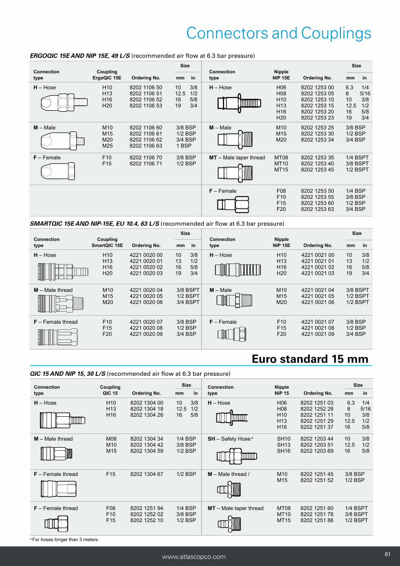
Size SizeConnection Coupling Connection Nipple type SmartQIC 15E Ordering No. mm in type NIP 15E Ordering No. mm in
H – Hose H10 4221 0020 00 10 3/8 H – Hose H10 4221 0021 00 10 3/8 H13 4221 0020 01 13 1/2 H13 4221 0021 01 13 1/2 H16 4221 0020 02 16 5/8 H16 4221 0021 02 16 5/8 H20 4221 0020 03 19 3/4 H20 4221 0021 03 19 3/4
M – Male thread M10 4221 0020 04 3/8 BSPT M – Male M10 4221 0021 04 3/8 BSPT M15 4221 0020 05 1/2 BSPT M15 4221 0021 05 1/2 BSPT M20 4221 0020 06 3/4 BSPT M20 4221 0021 06 1/2 BSPT
F – Female thread F10 4221 0020 07 3/8 BSP F – Female F10 4221 0021 07 3/8 BSP F15 4221 0020 08 1/2 BSP F15 4221 0021 08 1/2 BSP F20 4221 0020 09 3/4 BSP F20 4221 0021 09 3/4 BSP
ERGOQIC 15E AND NIP 15E, 49 L/S (recommended air flow at 6.3 bar pressure)
Size SizeConnection Coupling Connection Nipple type ErgoQIC 15E Ordering No. mm in type NIP 15E Ordering No. mm in
H – Hose H10 8202 1106 50 10 3/8 H – Hose H06 8202 1253 00 6.3 1/4H13 8202 1106 51 12.5 1/2 H08 8202 1253 05 8 5/16H16 8202 1106 52 16 5/8 H10 8202 1253 10 10 3/8H20 8202 1106 53 19 3/4 H13 8202 1253 15 12.5 1/2
H16 8202 1253 20 16 5/8H20 8202 1253 23 19 3/4
M – Male M10 8202 1106 60 3/8 BSP M – Male M10 8202 1253 25 3/8 BSP M15 8202 1106 61 1/2 BSP M15 8202 1253 30 1/2 BSP M20 8202 1106 62 3/4 BSP M20 8202 1253 34 3/4 BSP
M25 8202 1106 63 1 BSP
F – Female F10 8202 1106 70 3/8 BSP MT – Male taper thread MT08 8202 1253 35 1/4 BSPT F15 8202 1106 71 1/2 BSP MT10 8202 1253 40 3/8 BSPT MT15 8202 1253 45 1/2 BSPT
F – Female F08 8202 1253 50 1/4 BSP F10 8202 1253 55 3/8 BSP F15 8202 1253 60 1/2 BSP F20 8202 1253 63 3/4 BSP
SMARTQIC 15E AND NIP-15E, EU 10.4, 63 L/S (recommended air flow at 6.3 bar pressure)
Euro standard 15 mmQIC 15 AND NIP 15, 30 L/S (recommended air flow at 6.3 bar pressure)
a For hoses longer than 3 meters.
Connection Coupling Size Connection Nipple Sizetype QIC 15 Ordering No. mm in type NIP 15 Ordering No. mm in
H – Hose H10 8202 1304 00 10 3/8 H – Hose H06 8202 1251 03 6.3 1/4 H13 8202 1304 18 12.5 1/2 H08 8202 1252 28 8 5/16 H16 8202 1304 26 16 5/8 H10 8202 1251 11 10 3/8 H13 8202 1251 29 12.5 1/2 H16 8202 1251 37 16 5/8
M – Male thread M08 8202 1304 34 1/4 BSP SH – Safety Hose a SH10 8202 1203 44 10 3/8 M10 8202 1304 42 3/8 BSP SH13 8202 1203 51 12.5 1/2 M15 8202 1304 59 1/2 BSP SH16 8202 1203 69 16 5/8
F – Female thread F15 8202 1304 67 1/2 BSP M – Male thread / M10 8202 1251 45 3/8 BSP M15 8202 1251 52 1/2 BSP F – Female thread F08 8202 1251 94 1/4 BSP MT – Male taper thread MT08 8202 1251 60 1/4 BSPT F10 8202 1252 02 3/8 BSP MT10 8202 1251 78 3/8 BSPT F15 8202 1252 10 1/2 BSP MT15 8202 1251 86 1/2 BSPT

626262 www.atlascopco.com
Connectors and Couplings
08
08
08
ErgoQIC 08US
ISO 6150-B / US STANDARD
The ErgoQIC 08US is a full flow quick coupling with no air re-striction inside the coupling suitable for assembly tools, drills and small grinders. Upgrading any air system with ErgoQIC 08US will give the benefit of productivity and energy efficiency.
lFull flow coupling.lErgonomic design, small size and low weight.lStrong and durable.lSafety feature according to
EN 983 / ISO 4414.lMain market: North America, France, Norway and Spain.
Technical Data
Max flow capacity 17 l/s (0.5 bar ΔP)Economical air flow 11 l/s (0.2 bar ΔP)Max working pressure 16 barTemperature range -20ºC to 80ºC
Nipple profile
Technical DataMax flow capacity 12 l/s (0.5 bar ΔP)Economical air flow 8 l/s (0.2 bar ΔP)Max working pressure 16 barTemperature range -20ºC to +80ºC
SmartQIC 08US
ISO 6150-B / US STANDARD
Safety coupling with venting connection, high flow and low pressure drop.
lHigh reliability with low pressure drop.lSafety function with vented connectione.lHigh durability and easy handling.lHigh air flow and increased productivity.lMinimizes hose whip and injuries to operator.lLong life time.lSafety feature according to
ISO-standard 4414 and EN 983.lMain market: Benelux, France, Norway and North America.
Technical Data
Max flow capacity 16 l/s (0.5 bar ΔP)Economical air flow 15 l/s (0.2 bar ΔP)Max working pressure 16 barTemperature range -20ºC to +100ºC
Nipple profile
QIC 08US
ISO 6150-B / US STANDARD
The QIC 08US coupling is suitable for small screwdrivers and drills. Its lightweight, compact design makes the QIC 08US coupling easy to work with.
lHigh flow coupling.lOne-hand operation.lLow connection force.lMain market: North America, France, Norway and Spain.
Nipple profile
6363www.atlascopco.com
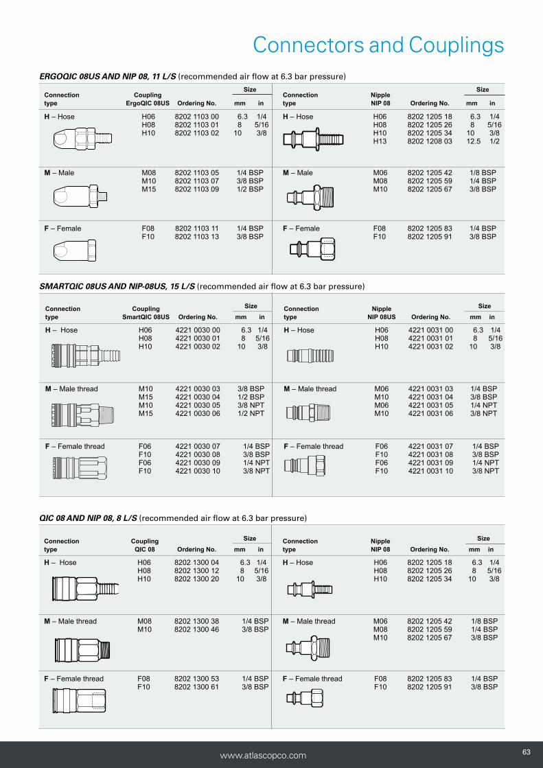
Connectors and CouplingsERGOQIC 08US AND NIP 08, 11 L/S (recommended air flow at 6.3 bar pressure)
Size SizeConnection Coupling Connection Nipple type ErgoQIC 08US Ordering No. mm in type NIP 08 Ordering No. mm in
H – Hose H06 8202 1103 00 6.3 1/4 H – Hose H06 8202 1205 18 6.3 1/4H08 8202 1103 01 8 5/16 H08 8202 1205 26 8 5/16H10 8202 1103 02 10 3/8 H10 8202 1205 34 10 3/8
H13 8202 1208 03 12.5 1/2
M – Male M08 8202 1103 05 1/4 BSP M – Male M06 8202 1205 42 1/8 BSP M10 8202 1103 07 3/8 BSP M08 8202 1205 59 1/4 BSP M15 8202 1103 09 1/2 BSP M10 8202 1205 67 3/8 BSP
F – Female F08 8202 1103 11 1/4 BSP F – Female F08 8202 1205 83 1/4 BSPF10 8202 1103 13 3/8 BSP F10 8202 1205 91 3/8 BSP
Connection Coupling Size Connection Nipple Sizetype QIC 08 Ordering No. mm in type NIP 08 Ordering No. mm in
H – Hose H06 8202 1300 04 6.3 1/4 H – Hose H06 8202 1205 18 6.3 1/4 H08 8202 1300 12 8 5/16 H08 8202 1205 26 8 5/16 H10 8202 1300 20 10 3/8 H10 8202 1205 34 10 3/8
M – Male thread M08 8202 1300 38 1/4 BSP M – Male thread M06 8202 1205 42 1/8 BSP M10 8202 1300 46 3/8 BSP M08 8202 1205 59 1/4 BSP M10 8202 1205 67 3/8 BSP
F – Female thread F08 8202 1300 53 1/4 BSP F – Female thread F08 8202 1205 83 1/4 BSP F10 8202 1300 61 3/8 BSP F10 8202 1205 91 3/8 BSP
QIC 08 AND NIP 08, 8 L/S (recommended air flow at 6.3 bar pressure)
SMARTQIC 08US AND NIP-08US, 15 L/S (recommended air flow at 6.3 bar pressure)
Connection Coupling Size Connection Nipple Sizetype SmartQIC 08US Ordering No. mm in type NIP 08US Ordering No. mm in
H – Hose H06 4221 0030 00 6.3 1/4 H – Hose H06 4221 0031 00 6.3 1/4 H08 4221 0030 01 8 5/16 H08 4221 0031 01 8 5/16 H10 4221 0030 02 10 3/8 H10 4221 0031 02 10 3/8
M – Male thread M10 4221 0030 03 3/8 BSP M – Male thread M06 4221 0031 03 1/4 BSP M15 4221 0030 04 1/2 BSP M10 4221 0031 04 3/8 BSP M10 4221 0030 05 3/8 NPT M06 4221 0031 05 1/4 NPT M15 4221 0030 06 1/2 NPT M10 4221 0031 06 3/8 NPT
F – Female thread F06 4221 0030 07 1/4 BSP F – Female thread F06 4221 0031 07 1/4 BSP F10 4221 0030 08 3/8 BSP F10 4221 0031 08 3/8 BSP F06 4221 0030 09 1/4 NPT F06 4221 0031 09 1/4 NPT F10 4221 0030 10 3/8 NPT F10 4221 0031 10 3/8 NPT

646464 www.atlascopco.com
Connectors and Couplings
10 10
Nipple profile
ErgoQIC 10US
ISO 6150-B / US STANDARD
The ErgoQIC 10US is a full flow quick coupling with no air re-striction inside the coupling suitable for assembly tools, drills and small grinders. Upgrading any air system with ErgoQIC 10US couplings will give the benefit of productivity and energy efficiency. It is interchangeable with US 3/8" standard nipples.
lFull flow coupling.lErgonomic design, small size and low weight.lStrong and durable.lSafety feature according to
EN 983 / ISO 4414.lMain market: North America, France, Norway and Spain.
Technical Data
Max flow capacity 43 l/s (0.5 bar ΔP)Economical air flow 27 l/s (0.2 bar ΔP)Max working pressure 16 barTemperature range -20ºC to 80ºC
Technical Data
Max flow capacity 43 l/s (0.5 bar ΔP)Economical air flow 39 l/s (0.2 bar ΔP)Max working pressure 16 barTemperature range -20ºC to +100ºC
SmartQIC 10US
ISO 6150-B / US STANDARD
Safety coupling with venting connection, high flow and low pressure drop.
lHigh reliability with low pressure drop.lSafety function with vented connectione.lHigh durability and easy handling.lHigh air flow and increased productivity.lMinimizes hose whip and injuries to operator.lLong life time.lSafety feature according to
ISO-standard 4414 and EN 983.lMain market: Benelux, France, Norway and North America.
Nipple profile
6565www.atlascopco.com
Connectors and Couplings
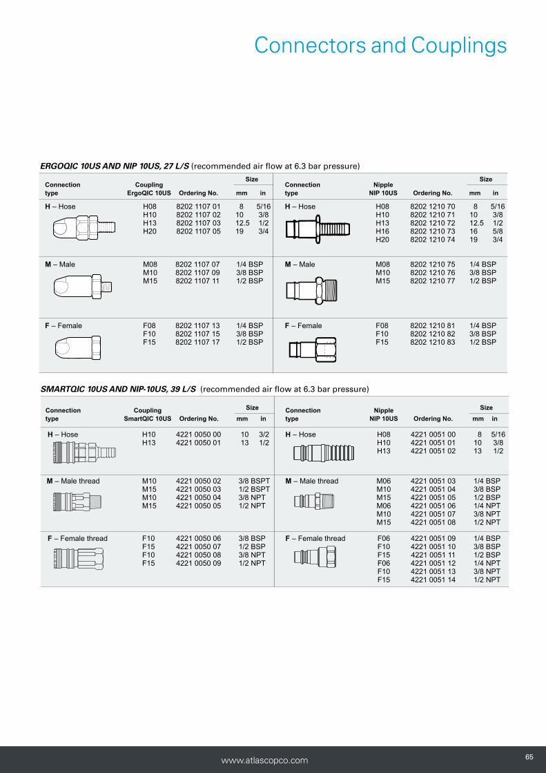
Size SizeConnection Coupling Connection Nipple type ErgoQIC 10US Ordering No. mm in type NIP 10US Ordering No. mm in
H – Hose H08 8202 1107 01 8 5/16 H – Hose H08 8202 1210 70 8 5/16 H10 8202 1107 02 10 3/8 H10 8202 1210 71 10 3/8 H13 8202 1107 03 12.5 1/2 H13 8202 1210 72 12.5 1/2 H20 8202 1107 05 19 3/4 H16 8202 1210 73 16 5/8 H20 8202 1210 74 19 3/4
M – Male M08 8202 1107 07 1/4 BSP M – Male M08 8202 1210 75 1/4 BSPM10 8202 1107 09 3/8 BSP M10 8202 1210 76 3/8 BSPM15 8202 1107 11 1/2 BSP M15 8202 1210 77 1/2 BSP
F – Female F08 8202 1107 13 1/4 BSP F – Female F08 8202 1210 81 1/4 BSPF10 8202 1107 15 3/8 BSP F10 8202 1210 82 3/8 BSPF15 8202 1107 17 1/2 BSP F15 8202 1210 83 1/2 BSP
ERGOQIC 10US AND NIP 10US, 27 L/S (recommended air flow at 6.3 bar pressure)
SMARTQIC 10US AND NIP-10US, 39 L/S (recommended air flow at 6.3 bar pressure)
Connection Coupling Size Connection Nipple Sizetype SmartQIC 10US Ordering No. mm in type NIP 10US Ordering No. mm in
H – Hose H10 4221 0050 00 10 3/2 H – Hose H08 4221 0051 00 8 5/16 H13 4221 0050 01 13 1/2 H10 4221 0051 01 10 3/8 H13 4221 0051 02 13 1/2
M – Male thread M10 4221 0050 02 3/8 BSPT M – Male thread M06 4221 0051 03 1/4 BSP M15 4221 0050 03 1/2 BSPT M10 4221 0051 04 3/8 BSP M10 4221 0050 04 3/8 NPT M15 4221 0051 05 1/2 BSP M15 4221 0050 05 1/2 NPT M06 4221 0051 06 1/4 NPT M10 4221 0051 07 3/8 NPT M15 4221 0051 08 1/2 NPT
F – Female thread F10 4221 0050 06 3/8 BSP F – Female thread F06 4221 0051 09 1/4 BSP F15 4221 0050 07 1/2 BSP F10 4221 0051 10 3/8 BSP F10 4221 0050 08 3/8 NPT F15 4221 0051 11 1/2 BSP F15 4221 0050 09 1/2 NPT F06 4221 0051 12 1/4 NPT F10 4221 0051 13 3/8 NPT F15 4221 0051 14 1/2 NPT
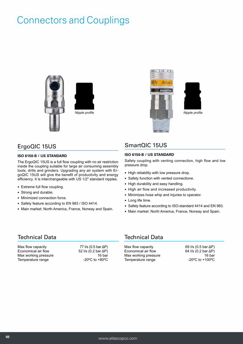
666666 www.atlascopco.com
Connectors and Couplings
1515
ErgoQIC 15US
ISO 6150-B / US STANDARD
The ErgoQIC 15US is a full flow coupling with no air restriction inside the coupling suitable for large air consuming assembly tools, drills and grinders. Upgrading any air system with Er-goQIC 15US will give the benefit of productivity and energy efficiency. It is interchangeable with US 1/2" standard nipples.
lExtreme full flow coupling.lStrong and durable.lMinimized connection force.lSafety feature according to EN 983 / ISO 4414.lMain market: North America, France, Norway and Spain.
Nipple profile
SmartQIC 15US
ISO 6150-B / US STANDARD
Safety coupling with venting connection, high flow and low pressure drop.
lHigh reliability with low pressure drop.lSafety function with vented connectione.lHigh durability and easy handling.lHigh air flow and increased productivity.lMinimizes hose whip and injuries to operator.lLong life time.lSafety feature according to ISO-standard 4414 and EN 983.lMain market: North America, France, Norway and Spain.
Nipple profile
Technical Data
Max flow capacity 77 l/s (0.5 bar ΔP)Economical air flow 52 l/s (0.2 bar ΔP)Max working pressure 16 barTemperature range -20ºC to +80ºC
Technical Data
Max flow capacity 69 l/s (0.5 bar ΔP)Economical air flow 64 l/s (0.2 bar ΔP)Max working pressure 16 barTemperature range -20ºC to +100ºC

6767www.atlascopco.com
Connectors and Couplings
Size
SizeConnection Coupling Connection Nipple
type ErgoQIC 15US Ordering No. mm in type NIP 15US Ordering No. mm in
H – Hose H10 8202 1108 02 10 3/8 H – Hose H10 8202 1215 40 10 3/8H13 8202 1108 03 12.5 1/2 H13 8202 1215 41 12.5 1/2H16 8202 1108 04 16 5/8 H16 8202 1215 42 16 5/8H20 8202 1108 05 19 3/4 H20 8202 1215 43 19 3/4
M – Male M10 8202 1108 09 3/8 BSP M – Male M08 8202 1215 44 1/4 BSP M15 8202 1108 11 1/2 BSP M10 8202 1215 45 3/8 BSP M15 8202 1215 46 1/2 BSP M20 8202 1215 47 3/4 BSP
F – Female F10 8202 1108 15 3/8 BSP F – Female F10 8202 1215 52 3/8 BSPF15 8202 1108 17 1/2 BSP F15 8202 1215 53 1/2 BSP
ERGOQIC 15US AND NIP 15US, 52 L/S (recommended air flow at 6.3 bar pressure)
SMARTQIC 15US AND NIP 15US, 8 L/S (recommended air flow at 6.3 bar pressure)
Connection Coupling Size Connection Nipple Sizetype SmartQIC 15US Ordering No. mm in type NIP 15US Ordering No. mm in
H – Hose H13 4221 0040 00 13 1/2 H – Hose H10 4221 0041 00 10 3/8 H20 4221 0040 02 19 3/4 H13 4221 0041 01 13 1/2 H20 4221 0041 03 19 3/4
M – Male thread M10 4221 0040 03 3/8 NPT M – Male thread M10 4221 0041 04 3/8 NPT M15 4221 0040 04 1/2 NPT M15 4221 0041 05 1/2 NPT M20 4221 0040 05 3/4 NPT M20 4221 0041 06 3/4 NPT
F – Female thread F10 4221 0040 06 3/8 NPT F – Female thread F10 4221 0041 07 3/8 NPT F15 4221 0040 07 1/2 NPT F15 4221 0041 08 1/2 NPT F20 4221 0040 08 3/4 NPT F20 4221 0041 09 3/4 NPT

686868 www.atlascopco.com
Connectors and Couplings
10 10
ErgoQIC 10AC
ATLAS COPCO GLOBAL STANDARD
The ErgoQIC 10AC is a full flow quick coupling with no air re-striction inside the coupling suitable for assembly tools, drills and small grinders. Upgrading any air system with ErgoQIC 10AC will give the benefit of productivity and energy efficiency.
lFull flow coupling.lErgonomic design, small size and low weight.lStrong and durable.lSafety feature according to EN 983 / ISO 4414.lMain market: Nordic, Benelux and Italy.
Nipple profile
QIC 10
ATLAS COPCO GLOBAL STANDARD
The QIC 10 is a small quick coupling suitable for assembly tools and drills. The QIC 10 can withstand extremely rough handling in tough applications.
lHigh flow coupling.lStrong and durable.lOne-hand operation.lMain market: Europe and Australia.
Nipple profile
Technical Data
Max flow capacity 24 l/s (0.5 bar ΔP)Economical air flow 15 l/s (0.2 bar ΔP)Max working pressure 16 barTemperature range -20ºC to +80ºC
Technical Data
Max flow capacity 26 l/s (0.5 bar ΔP)Economical air flow 17 l/s (0.2 bar ΔP)Max working pressure 16 barTemperature range -10ºC to +70ºC
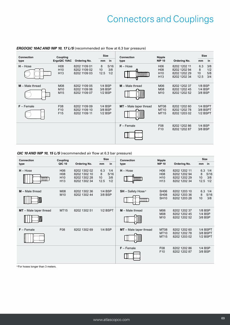
6969www.atlascopco.com
Connectors and Couplings
ERGOQIC 10AC AND NIP 10, 17 L/S (recommended air flow at 6.3 bar pressure)
Size
SizeConnection Coupling Connection Nipple
type ErgoQIC 10AC Ordering No. mm in type NIP 10 Ordering No. mm in
H – Hose H08 8202 1109 01 8 5/16 H – Hose H06 8202 1202 11 6.3 3/8H10 8202 1109 02 10 3/8 H08 8202 1202 94 8 1/2H13 8202 1109 03 12.5 1/2 H10 8202 1202 29 10 5/8
H13 8202 1202 34 12.5 3/4
M – Male thread M08 8202 1109 05 1/4 BSP M – Male thread M06 8202 1202 37 1/8 BSP M10 8202 1109 06 3/8 BSP M08 8202 1202 45 1/4 BSP M15 8202 1109 07 1/2 BSP M10 8202 1202 52 3/8 BSP
F – Female F08 8202 1109 09 1/4 BSP MT – Male taper thread MT08 8202 1202 60 1/4 BSPTF10 8202 1109 10 3/8 BSP MT10 8202 1202 78 3/8 BSPT
F15 8202 1109 11 1/2 BSP MT15 8202 1203 02 1/2 BSPT
F – Female F08 8202 1202 86 1/4 BSP
F10 8202 1202 87 3/8 BSP
QIC 10 AND NIP 10, 15 L/S (recommended air flow at 6.3 bar pressure)
Connection Coupling Size Connection Nipple Sizetype QIC 10 Ordering No. mm in type NIP 10 Ordering No. mm in
H – Hose H06 8202 1302 02 6.3 1/4 H – Hose H06 8202 1202 11 6.3 1/4 H08 8202 1302 10 8 5/16 H08 8202 1202 94 8 5/16 H10 8202 1302 28 10 3/8 H10 8202 1202 29 10 3/8 H13 8202 1302 34 12.5 1/2 H13 8202 1202 34 12.5 1/2
M – Male thread M08 8202 1302 36 1/4 BSP SH – Safety Hose a SH06 8202 1203 10 6.3 1/4 M10 8202 1302 44 3/8 BSP SH08 8202 1203 36 8 5/16 SH10 8202 1203 28 10 3/8
MT – Male taper thread MT15 8202 1302 51 1/2 BSPT M – Male thread M06 8202 1202 37 1/8 BSP M08 8202 1202 45 1/4 BSP M10 8202 1202 52 3/8 BSP
F – Female F08 8202 1302 69 1/4 BSP MT – Male taper thread MT08 8202 1202 60 1/4 BSPT MT10 8202 1202 78 3/8 BSPT MT15 8202 1203 02 1/2 BSPT
F – Female F08 8202 1202 86 1/4 BSP F10 8202 1202 87 3/8 BSP
a For hoses longer than 3 meters.

707070 www.atlascopco.com
Connectors and Couplings
10 10
ErgoQIC 10A
ASIA STANDARD 7.5 MM
The ErgoQIC 10 ASIA is a full flow coupling with no air restric-tion inside the coupling. It is suitable for assembly tools, drills and grinders. Upgrading any air system with ErgoQIC 10 ASIA will give the benefits of productivity and energy efficiency.
lExtreme full flow coupling.lStrong and durable.lMinimized connection force.lSafety feature according to EN 983 / ISO 4414.lMain market: Asia, Australia, Italy and South America.
Nipple profile
SmartQIC 10A
ASIA STANDARD 7.5 MM
Safety coupling with venting connection, high flow and low pressure drop.
lHigh reliability with low pressure drop.lSafety function with vented connectione.lHigh durability and easy handling.lHigh air flow and increased productivity.lMinimizes hose whip and injuries to operator.lLong life time.lSafety feature according to ISO-standard 4414 and EN 983.lMain market: Asia, Australia, Italy and South America.
Nipple profile
Technical Data
Max flow capacity 35 l/s (0.5 bar ΔP)Economical air flow 22 l/s (0.2 bar ΔP)Max working pressure 16 barTemperature range -10ºC to +70ºC
Technical Data
Max flow capacity 33 l/s (0.5 bar ΔP)Economical air flow 32 l/s (0.2 bar ΔP)Max working pressure 16 barTemperature range -20ºC to +100ºC

7171www.atlascopco.com
Connectors and Couplings
ERGOQIC 10 A AND NIP 10 A, 22 L/S (recommended air flow at 6.3 bar pressure)
Connection Coupling Size Connection Nipple Sizetype ErgoQIC 10 A Ordering No. mm in type NIP 10 A Ordering No. mm in
H – Hose H06 8202 1104 00 6.3 1/4 H – Hose H06 8202 1202 15 6.3 1/4H08 8202 1104 01 8 5/16 H08 8202 1202 16 8 5/16
H10 8202 1104 02 10 3/8 H10 8202 1202 17 10 3/8 H13 8202 1104 03 12.5 1/2 H13 8202 1202 18 12.5 1/2
MT – Male taper thread MT08 8202 1104 05 1/4 BSPT MT – Male taper thread MT06 8202 1202 19 1/8 BSPT MT10 8202 1104 06 3/8 BSPT MT08 8202 1202 20 1/4 BSPT MT15 8202 1104 07 1/2 BSPT MT10 8202 1202 21 3/8 BSPT
MT15 8202 1202 22 1/2 BSPT
FT – Female taper thread FT08 8202 1104 09 1/4 BSPT FT – Female taper thread FT08 8202 1202 23 1/4 BSPT FT10 8202 1104 10 3/8 BSPT FT10 8202 1202 24 3/8 BSPT FT15 8202 1104 11 1/2 BSPT FT15 8202 1202 25 1/2 BSPT
SMARTQIC 10A AND NIP 10A, 32 L/S (recommended air flow at 6.3 bar pressure)
Connection Coupling Size Connection Nipple Sizetype SmartQIC 10A Ordering No. mm in type NIP 10A Ordering No. mm in
H – Hose H06 4221 0060 00 6.3 1/4 H – Hose H06 4221 0061 00 6.3 1/4 H08 4221 0060 01 7 9/32 H08 4221 0061 01 7 9/32 H10 4221 0060 02 10 3/8 H10 4221 0061 02 10 3/8 H13 4221 0061 03 13 1/2
M – Male thread M06 4221 0060 03 1/4 R, BSP M – Male thread M06 4221 0061 04 1/4 R, BSP M10 4221 0060 04 3/8 R, BSP M10 4221 0061 05 3/8 R, BSP M15 4221 0060 05 1/2 R, BSP M15 4221 0061 06 1/2 R, BSP
F – Female thread F06 4221 0060 06 1/4 Rc, BSP F – Female thread F06 4221 0061 07 1/4 Rc,BSP F10 4221 0060 07 3/8 Rc, BSP F10 4221 0061 08 3/8 Rc,BSP F15 4221 0060 08 1/2 Rc, BSP F15 4221 0061 09 1/2 Rc,BSP

727272 www.atlascopco.com
Claw Couplings
Technical Data Economical air flow 280 12 l/s (0.2 bar P)Max working pressure 16 barTemperature range -10ºC to +80ºC
CLAW couplings are made from zinc-plated, dropforged, hardened steel, ensuring long life even under difficult conditions. The coupling head is the same for all hose sizes and can therefore be freely combined. The recommended maximum working pressure is 10 bar.
Connection Coupling Size Boretype CLAW Ordering No. mm in B, mmH – Hose H06 9000 0308 00 6.3 1/4 5.0 H10 9000 0309 00 10 3/8 8.0 H13 9000 0310 00 12.5 1/2 10.5 H16 9000 0311 00 16 5/8 13.5 H20 9000 0312 00 19 3/4 17.0 H25 9000 0313 00 25 1 22.0
LNH – Lock nut, Hose LNH10 9000 0260 00 10 3/8 8.0 LNH13 9000 0261 00 12.5 1/2 10.5 LNH16 9000 0262 00 16 5/8 13.5 LNH20 9000 0263 00 19 3/4 17.2 LNH25 9000 0264 00 25 1 22.0
M – Male thread M10 9000 0300 00 3/8 BSP 11.2 M15 9000 0301 00 1/2 BSP 14.8 M20 9000 0302 00 3/4 BSP 19.0 M25 9000 0303 00 1 BSP 25.5
F – Female thread F10 9000 0304 00 3/8 BSP 15.0 F15 9000 0305 00 1/2 BSP 18.6 F20 9000 0306 00 3/4 BSP 24.0 F25 9000 0307 00 1 BSP 25.0
Protection cover for 9000 0314 00CLAW couplings
Extra packing for For type H, M and F 9000 0000 00 (+80oC), 9000 0000 01 (+200oC) a
CLAW couplings For LNH10, -13 and -16 9000 0015 00 For LNH20 and -25 9000 0268 00 (+80oC), 9000 0319 00 (+200oC) a
Safety lock spring 3176 8640 90 25 pieces
a Viton-green.

7373www.atlascopco.com
Ball Valves
H
L
D
L
H
I
D
Dimensions
Connection Bore thread D L H IModel in BSP mm mm mm mm Ordering No.
BAL 08 1/4 9.5 50 41 - 8202 0301 05BAL 10 3/8 9.5 50 41 - 8202 0302 04BAL 15 1/2 12.5 60 43 - 8202 0303 03BAL 20 3/4 19 75 55 - 8202 0304 02BAL 25 1 24.5 90 64 - 8202 0305 01BAL-1A 08 1/4 8 43 44 73 8202 0306 03BAL-1A 10 3/8 10 50 47 73 8202 0306 11BAL-1A 15 1/2 15 61 53 94 8202 0306 29BAL-1A 20 3/4 20 70 57 94 8202 0306 37BAL-1A 25 1 25 83 67.5 122 8202 0306 45BAL-1A 32 1 1/4 32 100 83 150 8202 0306 52BAL-1A 40 1 1/2 38 107 87 150 8202 0306 60BAL-1A 50 2 50 129 103 193 8202 0306 78
Suitable for air, water and many other liquids and
gases due to the choice of material.
BAL – with nitrile rubber sealsCan be used in all settings between fully open and fully closed. The balls and the seals can be replaced without the body being removed from the piping.
BAL-1A – with teflon sealsIntended for operating either fully open or fully closed.
BAL1A
BAL
BAL
Maximum working pressure: 16 bar.
Working temperature range: -20oC to +90oC.
BAL-1A Maximum working pressure: 16 bar(BAL-1A 40 and 50: max. 16 bar up to +100oC).
Working temperature range: -30oC to +200oC. (BAL-1A 40 and 50: at +200oC max. working pressure is reduced to 8 bar).
Technical Data

747474 www.atlascopco.com
Swivel Connectors
Max rec. Thread
air flow a Inlet female Outlet male Weight Length Dia Model l/s cfm in in g mm mm Ordering No.
StandardMultiFlex 1/8" BSP 12 25 1/8 1/8 73 66.2 24 8202 1350 18MultiFlex 1/4" BSP 12 25 1/4 1/4 73 66.2 24 8202 1350 20MultiFlex 3/8" BSP 32 68 3/8 3/8 130 80.6 29.5 8202 1350 22MultiFlex 1/2" BSP 32 68 1/2 1/2 125 80.6 29.5 8202 1350 24Protective rubber coverMultiFlex 1/8" BSP 12 25 1/8 1/8 76 66.2 27 8202 1350 40MultiFlex 1/4" BSP 12 25 1/4 1/4 76 66.2 27 8202 1350 41MultiFlex 3/8" BSP 32 68 3/8 3/8 130 80.6 29.5 8202 1350 42High air flow MultiFlex 1/2" BSP 54 114 1/2 1/2 326 98.3 39 8202 1350 60
The MultiFlex swivel is an ingenious multi-directional connector. Connect your tool and the hose will stay in the ideal position however much you and the tool move around.
The MultiFlex bends and rotates 360º in all directions while the hose stays straight. The hose feels almost weightless and hose wear is reduced. Safety factor 4 on MultiFlex couplings. Maximum recommended working pressure is 10 bar.
MultiFlex swivelMulti-directional connector

7575www.atlascopco.com
Fittings
Recommended flow max 10 l/s
Medium pressure clamps for RUBBER HOSES
Hose connectionMale thread – hose nipple Simple pressure clamps for PVC HOSES
One-lugged For For steel clamp CABLAIR PVC mm Ordering No.
– – 5.2- 6.2 0347 0122 18 – – 5.9- 7.0 0347 0122 19 – 03 7.0- 8.5 0347 0122 05 06 05 8.5-10.0 0347 0122 06 08 06 9.8-11.8 0347 0122 07 – 08 11.3-13.3 0347 0122 08 10 – 12.8-14.8 0347 0122 09 – 10 14.6-16.8 0347 0122 10 13 – 16.5-18.8 0347 0122 11 – 13 18.0-20.3 0347 0122 12 16 – 20.2-22.8 0347 0122 13 – – 22.0-24.8 0347 0122 14 20 – 23.3-26.3 0347 0122 15 – – 26.5-30.0 0347 0122 16 25 – 29.8-33.1 0347 0122 22
Medium clamp For For worm drive TURBO RUBAIR mm Ordering No.
– 06 11.0-17.0 0347 6103 00 13 10 13.0-20.0 0347 6104 00 16 13 15.0-24.0 0347 6105 00 – 16 19.0-28.0 0347 6106 00 20 – 22.0-32.0 0347 6107 00 – 20 26.0-38.0 0347 6109 00
Gaskets
For couplings Fiber gasket between with male parallel material and nipple thread Ordering No.
M5 0657 5710 00 1/8 BSP 0657 5742 00 1/4 BSP 0657 5764 00 3/8 BSP 0657 5785 00 1/2 BSP 0653 0500 01 3/4 BSP 0657 5823 00 1 BSP 0657 5830 00
For Medium clamp For PVC, worm drive CABLAIR POLUR mm Ordering No.
– – 8.0-14.0 0347 6102 00 – 08 11.0-17.0 0347 6103 00 – 10 11.0-17.0 0347 6103 00 – – 13.0-20.0 0347 6104 00 16 13 15.0-24.0 0347 6105 00 20 16 19.0-28.0 0347 6106 00 – 20 22.0-32.0 0347 6107 00 25 25 26.0-38.0 0347 6109 00 – – 32.0-44.0 0347 6111 00 – – 38.0-50.0 0347 6112 00 – – 50.0-65.0 0347 6113 00
Medium pressure clamps for PVC HOSES
Swivels
Reducing nipple in brass
Female thread Male thread in in Ordering No.
1/4 BSP 1/8 BSP 9721 4000 94 3/8 BSP 1/4 BSP 9721 4000 92 1/2 BSP 3/8 BSP 9721 4000 93
Hose size Thread in mm in Ordering No.
1/8 BSP 3.2 1/8 9000 0523 001/8 BSPT 5 3/16 4010 0031 001/8 BSPT 6.3 1/4 9000 0240 001/4 BSP 3.2 1/8 9000 0524 001/4 BSPT 6.3 1/4 9000 0241 001/4 BSPT 8 5/16 9090 1715 001/4 BSPT 10 3/8 9000 0247 003/8 BSPT 10 3/8 9000 0242 003/8 BSPT 12.5 1/2 9000 0248 001/2 BSPT 12.5 1/2 9000 0243 001/2 BSPT 16 5/8 9000 0244 001/2 BSP 20 3/4 4150 0429 003/4 BSPT 20 3/4 9000 0245 00 1 BSPT 25 1 9000 0246 00
Air outlet Max Swivel Air Male bend from inlet BSP centre line Ordering No.
5/16" hose 1/4 30° 4210 3134 80

767676 www.atlascopco.com
Fittings
Heavy-duty For For clamp TURBO RUBAIR mm Ordering No. – – 22.0-25.0 9000 0194 00 20 16 25.0-28.0 9000 0195 00 – 20 29.0-32.0 9000 0196 00 – 25 34.0-38.0 9000 0197 00
Heavy-duty pressure clamps for RUBBER HOSES
1
1
21
2
Male Female thread thread in in Ordering No.
1/4 BSP 1/8 BSP 9090 0799 00 3/8 BSP 1/4 BSP 9090 0798 00 1/2 BSP 1/4 BSP 9090 1469 00 1/2 BSP 3/8 BSP 9090 0797 00 3/4 BSP 1/2 BSP 9090 0796 00 1 BSPT 3/4 BSP 9090 0795 00
BushingMale thread – female thread
Double connectionMale taper thread – male taper thread
From To thread thread in in Ordering No.
1/8 BSPT 1/8 BSPT 9090 0100 00 1/8 BSPT 1/4 BSPT 9090 0110 00 1/4 BSPT 1/4 BSPT 9090 0120 00 1/4 BSPT 3/8 BSPT 9090 0130 00 3/8 BSPT 3/8 BSPT 9090 0140 00 3/8 BSPT 1/2 BSPT 9090 0150 00 1/2 BSPT 1/2 BSPT 9090 0160 00 1/2 BSPT 3/4 BSPT 9090 0170 00 3/4 BSPT 3/4 BSPT 9090 0180 00 3/4 BSPT 1 BSPT 9090 0190 00 1 BSPT 1 BSPT 9090 0200 00
Hose connection with clamp nut and spring guard
Clamp nut, brass
Hose diameter Outside/Inside Male thread mm in Ordering No.
10/8 1/4 BSP 9721 4002 89 10/8 3/8 BSP 9721 4002 90 12/9 1/4 BSP 9721 4000 86 12/10 3/8 BSP 9721 4000 88 15/12.5 1/2 BSP 9721 4000 89
Male threaded hose nipple with clamp nut should be used with female threaded quick couplings.
Spring guard in steel
Hose diameter Outside/Inside mm Ordering No.
10/8 9721 4002 88 12/10 9721 4000 91 15/12 9721 4002 85
The spring guard should be used with the clamp nut above.
Double adjustable connectionMale thread – male thread
From To thread thread
in in Ordering No. 1/2 BSP 1/2 BSP 9090 0806 00
Sealing rings for double adjustable connection
Spare rubber For coupling sealing ring for with male thread adjustable connections
in Ordering No.
1/2 BSP 9090 0884 00 1 BSP 9090 0886 00
Manifolds3/8 inlet on each side, 1/4 outlets for couplings
Thread Number Inlet Outlet of in in outlets Ordering No.
3/8 BSP 1/4 BSP 4 9090 0201 00 3/8 BSP 1/4 BSP 5 9090 0201 01 3/8 BSP 1/4 BSP 6 9090 0201 02
Manifolds 3/8 inlet on each side, 1/4 outlet on both sides for couplings
Thread Number Inlet Outlet of in in outlets Ordering No.
3/8 BSP 1/4 BSP 4 9090 0201 10 3/8 BSP 1/4 BSP 6 9090 0201 11 3/8 BSP 1/4 BSP 8 9090 0201 12 3/8 BSP 1/4 BSP 10 9090 0201 13
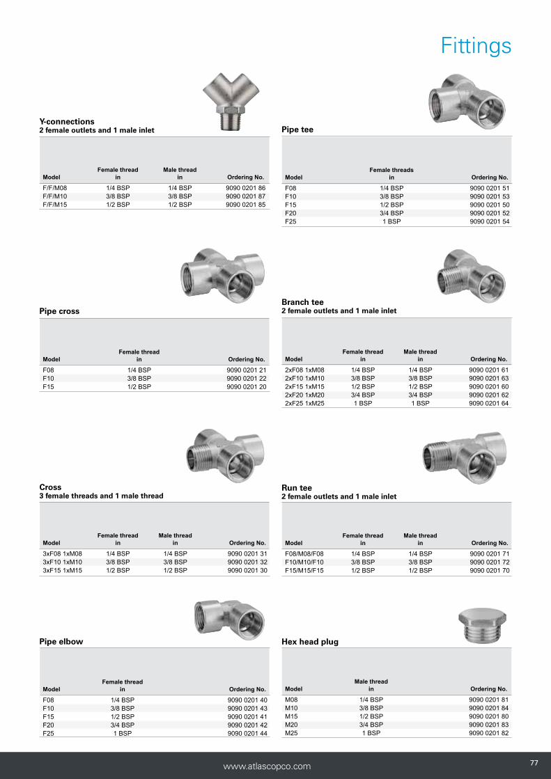
7777www.atlascopco.com
Fittings
Hex head plug
Pipe cross
Female thread Model in Ordering No.
F08 1/4 BSP 9090 0201 21F10 3/8 BSP 9090 0201 22F15 1/2 BSP 9090 0201 20
Cross3 female threads and 1 male thread
Female thread Male thread Model in in Ordering No.
3xF08 1xM08 1/4 BSP 1/4 BSP 9090 0201 313xF10 1xM10 3/8 BSP 3/8 BSP 9090 0201 323xF15 1xM15 1/2 BSP 1/2 BSP 9090 0201 30
Pipe tee
Female threadsModel in Ordering No.
F08 1/4 BSP 9090 0201 51F10 3/8 BSP 9090 0201 53F15 1/2 BSP 9090 0201 50F20 3/4 BSP 9090 0201 52F25 1 BSP 9090 0201 54
Branch tee2 female outlets and 1 male inlet
Female thread Male thread Model in in Ordering No.
2xF08 1xM08 1/4 BSP 1/4 BSP 9090 0201 612xF10 1xM10 3/8 BSP 3/8 BSP 9090 0201 632xF15 1xM15 1/2 BSP 1/2 BSP 9090 0201 602xF20 1xM20 3/4 BSP 3/4 BSP 9090 0201 622xF25 1xM25 1 BSP 1 BSP 9090 0201 64
Run tee2 female outlets and 1 male inlet
Female thread Male thread Model in in Ordering No.
F08/M08/F08 1/4 BSP 1/4 BSP 9090 0201 71F10/M10/F10 3/8 BSP 3/8 BSP 9090 0201 72F15/M15/F15 1/2 BSP 1/2 BSP 9090 0201 70
Male thread Model in Ordering No.
M08 1/4 BSP 9090 0201 81M10 3/8 BSP 9090 0201 84M15 1/2 BSP 9090 0201 80M20 3/4 BSP 9090 0201 83M25 1 BSP 9090 0201 82
Pipe elbow
Female thread Model in Ordering No.
F08 1/4 BSP 9090 0201 40F10 3/8 BSP 9090 0201 43F15 1/2 BSP 9090 0201 41F20 3/4 BSP 9090 0201 42F25 1 BSP 9090 0201 44
Y-connections2 female outlets and 1 male inlet
Female thread Male thread Model in in Ordering No.
F/F/M08 1/4 BSP 1/4 BSP 9090 0201 86F/F/M10 3/8 BSP 3/8 BSP 9090 0201 87F/F/M15 1/2 BSP 1/2 BSP 9090 0201 85
787878 www.atlascopco.com
Hoses

7979www.atlascopco.com
Internal hose diameter (mm)
Pressure drop diagram for hoses
185
150
125
100
50
20
15
10
5
2
1,5
2 4 6 8 10 12
Air
flow
(fre
e ai
r) l/
s
Inlet pressure 7 barPressure drop 0.2 barTwo hose nipples included
Hose length (m)
25
20
16
13
10
08
06
05
Get the best air flow!
Atlas Copco Tools has several different hoses covering all types of needs for pneumatic hand tools.
The diagram helps you to choose the right hose according to the air consumption of the tool and the length of the hose. The purpose of the diagram is to ensure that the pressure drop in the hoses does not exceed 0.2 bar.
How to find correct internal hose diameter:
1. Find the required air consumption for the tool at 6 bar and the required hose length.
2. Use the required hose length and air flow to find required hose size.
Example The tool has an air consumption of 10 l/s and the application requires a hose length of 7 m. These two values have a cross point slightly under the 10 mm size hose (7 m of 10 mm hose gives a value of approximately 11 I/s).Therefore a 10 mm hose will be suitable.
• Covering all types of needs for pneumatic tools for various envi-ronments
• Choose between many types of rubber or PVC hoses.
• Rubber hoses are grinding and welding spatter resistant.
• Available as pre-mounted hose kits.

808080 www.atlascopco.com
Rubber Hoses
TURBO Super-light flexible rubber hose
The Turbo hose has been developed for both indoor and outdoor use. The hose weighs 30–40% less than conventional rubber hoses. Turbo hose is oil resistant.
• Extremely low weight.• Soft and flexible.• Antistatic.• Grinding and welding spatter resistant.• Working temperature -30ºC to +70ºC.
RUBBER Durable, reinforced, extra thick, heavy duty rubber hoseWithstands rough handling and is suitable for the most demanding industrial tasks. The inner lining is black EPDM rubber and the hose is conductive to dissipate static electricity. Reinforced with synthetic textile yarns that provide high tensile strength.
• Durable. • Grinding and welding spatter resistant. • Working temperature -25ºC to +70ºC.
Hose Hose Max inside outside working Max rec. Weight per dia dia pressure a air flow b 20 m coil 30 m coilModel mm in mm bar l/s kg kg Ordering No.
RUBBER 6.3 1/4 12 16 4 30 3.5 9030 2036 00RUBBER 10 3/8 17 16 13 30 6.9 9030 2037 00RUBBER 12.5 1/2 22 16 21 30 12.3 9030 2038 00RUBBER 16 5/8 25 16 43 30 13.9 9030 2039 00RUBBER 20 3/4 30 16 75 30 19.3 9030 2040 00RUBBER 25 1 36 16 125 30 24.0 9030 2041 00
a With a safety factor of 3 at 20°C.b The pressure drop will be 0.2 bar on a hose length of 5 m, including 2 nipples and at an inlet pressure of 7 bar.
Model
Hoseinside
dia
Hoseoutside
dia
Max working
pressure a
Max recair flow b.
Lenght of coil Weight of coil Ordering No.
mm in mm bar psi l/s cfm m ft kg lbsTURBO 13 13 1/2 19 20 290 21 44,4 20 65 3.9 8.6 9093 0057 91TURBO 16 16 5/8 22.8 20 290 43 91 20 65 4.8 10.6 9093 0057 31 TURBO 20 20 3/4 27.5 20 290 75 159 20 65 5.4 11.9 9093 0057 61
TURBO 13 13 1/2b 19 20 290 21 44.5 30 98 5.9 13 9093 0057 93TURBO 16 16 5/8 22.8 20 290 43 91 30 98 7.2 15.9 9093 0057 33TURBO 20 20 3/4 27.5 20 290 75 159 30 98 8.1 17.9 9093 0057 62
TURBO 13 13 1/2 19 20 290 21 44.5 50 164 9 19.8 9093 0057 95a With a safety factor of 3 at 20°C.b The pressure drop will be 0.2 bar on a hose length of 5 m, including 2 nipples and at an inlet pressure of 7 bar.

8181www.atlascopco.com
Rubber Hoses
RUBAIR Durable reinforced heavy duty rubber hoseRubair hose is double reinforced to fulfil all general heavy duty demands and is recommended for indoor and outdoor use. Rubair hose is oil resistant.
• Durable.• Antistatic.• Grinding and welding spatter resistant.• Working temperature -20ºC to +80ºC.
a With a safety factor of 4 at 20°C.b The pressure drop will be 0.2 bar on a hose length of 5 m, including 2 nipples and at an inlet pressure of 7 bar.
Hose Hose Max inside outside working Max rec. Weight per dia dia pressure a air flow b 20 m coli Model mm in mm bar l/s kg Ordering No.
RUBAIR 10 10 3/8 16.0 16 13 3.6 8202 0402 10RUBAIR 13 12.5 1/2 19.1 16 21 4.7 8202 0403 13RUBAIR 16 16 5/8 23.0 16 43 6.1 8202 0404 16RUBAIR 20 20 3/4 26.6 16 75 7.8 8202 0405 20

828282 www.atlascopco.com
CABLAIR Super-light flexible PVC-hose
Cablair is made of high-strength and high performance PVC compound. The Cablair hose weighs 30–50% less, is much softer and more flexible than conventional PVC hoses.
• Low weight.• Extremely soft and
flexible.• Silicone free.
• Ergonomic.• Working temp. -15ºC
to +60ºC.
CABLAIR ESD Extra flexible antistatic air hose
Cablair ESD is designed specifically for the computer manufacturing industry. The hose possesses properties which enable ESDS (electrostatic sensitive devices) to be handled in a protected area with a low risk level, as a result of electrostatic discharge. The connection device must be earthed/grounded.
• Extra flexible.• Antistatic.• Silicone free.
• Testing in accordance with BS ISO 2878:2005.
• Working temp. -15ºC to +60ºC.
a With a safety factor of 3 at 20°C (at the max temp of +60°C the working pressure should be reduced by 50%).
Hose Hose Max inside outside working Max rec. Weight per dia dia pressure a air flow b 30 m coli Model mm in mm in bar l/s kg Ordering No.
CABLAIR ESD 06 6 1/4 11 7/16 10 4 2.34 8202 0501 06CABLAIR ESD 08 8 5/16 12 1/2 9 7.5 2.56 8202 0501 08CABLAIR ESD 10 10 3/8 14 9/16 8 13 2.71 8202 0501 10CABLAIR ESD 13 13 1/2 18 23/32 7 21 4.41 8202 0501 13
Hose Hose Max inside outside working Max rec. Weight per dia dia pressure a air flow b 30 m coli Model mm in mm bar l/s kg Ordering No.
CABLAIR 06 6 1/4 8.5 14 4 1.2 9093 0035 11CABLAIR 08 8 1/3 11 14 7.5 1.7 9093 0035 41CABLAIR 10 10 2/5 13 12 13 2.1 9093 0035 71CABLAIR 13 12.5 1/2 16 11 21 3.0 9093 0036 01CABLAIR 16 16 5/8 21 8 43 5.4 9093 0036 31CABLAIR 20 19 3/4 24 8 75 5.8 9093 0036 61CABLAIR 25 25 1 31.5 7 125 10.4 9093 0036 91
a With a safety factor of 3 at 20°C (at the max temp of +60°C the working pressure should be reduced by 50%).b The pressure drop will be 0.2 bar on a hose length of 5 m.
PVC Hoses

8383www.atlascopco.com
PVC Hose for heavy-duty applicationsPVC hose has high resistance to abrasion, which makes it the ideal hose for tough working environments. It is mainly recommended for indoor use.
• Long service life.• Pliable.• Transparent.• Working temperature -15ºC to +60ºC.
Hose inside Hose Max working Max rec. Weight per dia outside dia pressure a air flow b 30 m coilModel mm in mm bar l/s kg Ordering No.
PVC 03 3.2 1/8 7 20 0.7 1.4 9093 0037 21PVC 05 5 3/16 9 10 2.1 1.9 9093 0037 51PVC 06 6.3 1/4 11 10 4 2.5 9093 0037 81PVC 08 8 5/16 12 10 7.5 2.9 9093 0038 11PVC 10 10 3/8 14 14 13 3.7 9093 0038 41PVC 13 12.5 1/2 18 13 21 5.9 9093 0038 71PVC 16 16 5/8 22 12 43 7.2 9093 0039 01PVC 20 19 3/4 25 10 75 8.3 9093 0039 31 PVC 25 25 1 32 10 125 12.5 9093 0039 61
a With a safety factor of 3 at 20°C (at the max temp of +60°C the working pressure should be reduced by 50%).b The pressure drop will be 0.2 bar on a hose length of 5 m.
POLUR High resistance polyurethane hose
Polur hose is the most environmentally friendly solution. It has high resistance to abrasion and it is oil resistant. Polur hose has a much longer lifetime than PVC hoses. Polur is ideal in tough working conditions due to its flexibility, even at minus degrees. Polur is recommended for indoor and outdoor use.
• Oil resistant.• Flexible.• Long service life.• Working temperature -30ºC to +60ºC.
a With a safety factor of 3 at 20°C (at the max temp of +60°C the working pressure should be reduced by 50%).b The pressure drop will be 0.2 bar on a hose length of 5 m, including 2 nipples and at an inlet pressure of 7 bar.
Hose Hose Max working Max rec. Weight per inside dia outside dia pressure a air flow b 25 m coilModel mm in mm bar l/s kg Ordering No.
POLUR 08 8 5/16 12 20 7.5 2.2 8202 0601 08 POLUR 10 10 3/8 14 16 13 2.5 8202 0602 10 POLUR 13 13 1/2 18 13 21 4.0 8202 0603 13
PVC Hoses
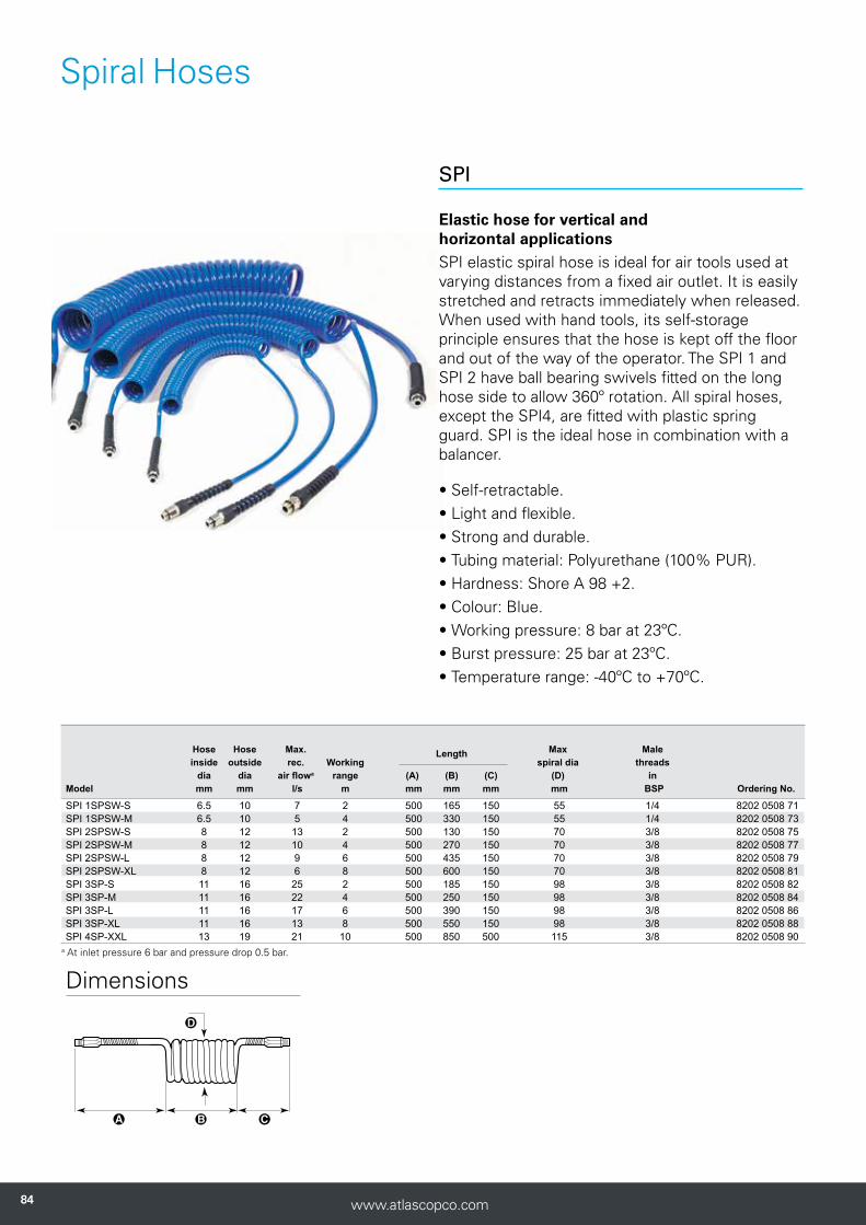
848484 www.atlascopco.com
Spiral Hoses
a At inlet pressure 6 bar and pressure drop 0.5 bar.
Hose Hose Max. Max Male inside outside rec. Working
Length spiral dia threads
dia dia air flowa range (A) (B) (C) (D) in Model mm mm l/s m mm mm mm mm BSP Ordering No.
SPI 1SPSW-S 6.5 10 7 2 500 165 150 55 1/4 8202 0508 71SPI 1SPSW-M 6.5 10 5 4 500 330 150 55 1/4 8202 0508 73SPI 2SPSW-S 8 12 13 2 500 130 150 70 3/8 8202 0508 75SPI 2SPSW-M 8 12 10 4 500 270 150 70 3/8 8202 0508 77SPI 2SPSW-L 8 12 9 6 500 435 150 70 3/8 8202 0508 79SPI 2SPSW-XL 8 12 6 8 500 600 150 70 3/8 8202 0508 81SPI 3SP-S 11 16 25 2 500 185 150 98 3/8 8202 0508 82SPI 3SP-M 11 16 22 4 500 250 150 98 3/8 8202 0508 84SPI 3SP-L 11 16 17 6 500 390 150 98 3/8 8202 0508 86SPI 3SP-XL 11 16 13 8 500 550 150 98 3/8 8202 0508 88SPI 4SP-XXL 13 19 21 10 500 850 500 115 3/8 8202 0508 90
Dimensions
SPI Elastic hose for vertical and horizontal applicationsSPI elastic spiral hose is ideal for air tools used at varying distances from a fixed air outlet. It is easily stretched and retracts immediately when released. When used with hand tools, its self-storage principle ensures that the hose is kept off the floor and out of the way of the operator. The SPI 1 and SPI 2 have ball bearing swivels fitted on the long hose side to allow 360º rotation. All spiral hoses, except the SPI4, are fitted with plastic spring guard. SPI is the ideal hose in combination with a balancer.
• Self-retractable.• Light and flexible.• Strong and durable.• Tubing material: Polyurethane (100% PUR).• Hardness: Shore A 98 +2.• Colour: Blue.• Working pressure: 8 bar at 23ºC.• Burst pressure: 25 bar at 23ºC.• Temperature range: -40ºC to +70ºC.
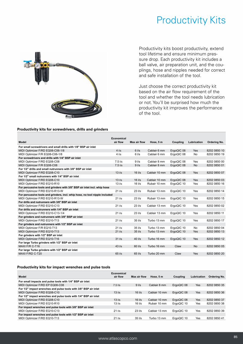
8585www.atlascopco.com
Productivity Kits
Economical Model air flow Max air flow Hose, 5 m Coupling Lubrication Ordering No.
For small screwdrivers and small drills with 1/8" BSP air inlet MIDI Optimizer F/RD EQ08-C06-1/8 4 l/s 6 l/s Cablair 6 mm ErgoQIC 08 Yes 8202 0850 10 MIDI Optimizer F/R EQ08-C06-1/8 4 l/s 6 l/s Cablair 6 mm ErgoQIC 08 No 8202 0850 19 For screwdrivers and drills with 1/4" BSP air inlet MIDI Optimizer F/RD EQ08-C08 7.5 l/s 9 l/s Cablair 8 mm ErgoQIC 08 Yes 8202 0850 00 MIDI Optimizer F/R EQ08-C08 7.5 l/s 9 l/s Cablair 8 mm ErgoQIC 08 No 8202 0850 01 For 1/2" drills and small nutrunners with 3/8" BSP air inlet MIDI Optimizer F/RD EQ08-C10 13 l/s 16 l/s Cablair 10 mm ErgoQIC 08 Yes 8202 0850 07 For 1/2" small nutrunners with 1/4" BSP air inlet MIDI Optimizer F/RD EQ08-C10 13 l/s 16 l/s Cablair 10 mm ErgoQIC 08 Yes 8202 0850 03 MIDI Optimizer F/RD EQ10-R10 13 l/s 16 l/s Rubair 10 mm ErgoQIC 10 Yes 8202 0850 16 For percussive tools and grinders with 3/8" BSP air inlet incl. whip hose MIDI Optimizer F/RD EQ10-R13-W 21 l/s 23 l/s Rubair 13 mm ErgoQIC 10 Yes 8202 0850 14 For percussive tools and grinders, incl. whip hose, no tool nipple included MIDI Optimizer F/RD EQ10-R13-W 21 l/s 23 l/s Rubair 13 mm ErgoQIC 10 Yes 8202 0850 15 For drills and nutrunners with 3/8" BSP air inlet MIDI Optimizer F/RD EQ10-C13 21 l/s 23 l/s Cablair 13 mm ErgoQIC 10 Yes 8202 0850 02 For drills and nutrunners with 1/4" BSP air inlet MIDI Optimizer F/RD EQ10-C13-1/4 21 l/s 23 l/s Cablair 13 mm ErgoQIC 10 Yes 8202 0850 11 For grinders and nutrunners with 3/8" BSP air inlet MIDI Optimizer F/RD EQ10-T13 21 l/s 35 l/s Turbo 13 mm ErgoQIC 10 Yes 8202 0850 17 For grinders and nutrunners with 1/2" BSP air inlet MIDI Optimizer F/R EQ10-T13 21 l/s 35 l/s Turbo 13 mm ErgoQIC 10 No 8202 0850 04 MIDI Optimizer F/RD EQ10-T13 21 l/s 35 l/s Turbo 13 mm ErgoQIC 10 Yes 8202 0850 13 For grinders with 1/2" BSP air inlet MIDI Optimizer F/RD EQ10-T16 31 l/s 40 l/s Turbo 16 mm ErgoQIC 10 Yes 8202 0850 12 For large Turbo grinders with 1/2" BSP air inlet MAXI F/R C-T16 43 l/s 60 l/s Turbo 16 mm Claw No 8202 0850 05 For large Turbo grinders with 1/2" BSP air inlet MAXI F/RD C-T20 65 l/s 65 l/s Turbo 20 mm Claw Yes 8202 0850 20
Productivity kits for screwdrivers, drills and grinders
Productivity kits for impact wrenches and pulse tools
EconomicalModel air flow Max air flow Hose, 5 m Coupling Lubrication Ordering No.
For small impacts and pulse tools with 1/4" BSP air inlet MIDI Optimizer F/RD EP EQ08-C08 7.5 l/s 9 l/s Cablair 8 mm ErgoQIC 08 Yes 8202 0850 35For 1/2" impact wrenches and pulse tools with 3/8" BSP air inlet MIDI Optimizer F/RD EQ08-C10 13 l/s 16 l/s Cablair 10 mm ErgoQIC 08 Yes 8202 0850 36For 1/2" impact wrenches and pulse tools with 1/4" BSP air inlet MIDI Optimizer F/RD EQ08-C10 13 l/s 16 l/s Cablair 10 mm ErgoQIC 08 Yes 8202 0850 37MIDI Optimizer F/RD EQ10-R10 13 l/s 16 l/s Rubair 10 mm ErgoQIC 10 Yes 8202 0850 38For impact wrenches and pulse tools with 3/8" BSP air inlet MIDI Optimizer F/RD EQ10-C13 21 l/s 23 l/s Cablair 13 mm ErgoQIC 10 Yes 8202 0850 39For impact wrenches and pulse tools with 1/2" BSP air inlet MIDI Optimizer F/RD EQ10-T13 21 l/s 35 l/s Turbo 13 mm ErgoQIC 10 Yes 8202 0850 41
Productivity kits boost productivity, extend tool lifetime and ensure minimum pres-sure drop. Each productivity kit includes a ball valve, air preparation unit, and the cou-plings, hose and nipples needed for correct and safe installation of the tool.
Just choose the correct productivity kit based on the air flow requirement of the tool and whether the tool needs lubrication or not. You’ll be surprised how much the productivity kit improves the performance of the tool.

868686 www.atlascopco.com
Hose Kits
Pre-mounted hose kits Atlas Copco hose kits give you the correct combination of hose and coupling so that you don't need to spend time choosing and mounting.
• Correct combination hose – coupling.• Immediate use.
Dia Length Air inletHose mm m Nipple Coupling thread nipple Ordering No.
Cablair 6 5 ErgoNIP 08 ErgoQIC 08 - 8202 1182 01Cablair 6 5 NIP 08 ErgoQIC 08US - 8202 1182 16Cablair 6 5 ErgoNIP 10 ErgoQIC 10 1/8" BSP 8202 1180 67Cablair 6 5 ErgoNIP 10 ErgoQIC 10 1/4" BSP 8202 1182 01Cablair 8 5 ErgoNIP 08 ErgoQIC 08 1/4" BSP 8202 1182 02Cablair 8 5 NIP 08 ErgoQIC 08US - 8202 1182 21Cablair 8 5 ErgoNIP 10 ErgoQIC 08 1/4" BSP 8202 1180 77Cablair 10 5 ErgoNIP 08 ErgoQIC 08 1/4" BSP 8202 1182 03Cablair 10 5 ErgoNIP 10 ErgoQIC 10 1/8" BSP 8202 1180 30Cablair 13 5 ErgoNIP 10 ErgoQIC 10 3/8" BSP 8202 1180 79Cablair 13 5 ErgoNIP 10 ErgoQIC 10 - 8202 1182 10Cablair 13 5 NIP 10US ErgoQIC 10US - 8202 1182 18Cablair 13 8.5 ErgoNIP 10 ErgoQIC 10 - 8202 1182 20Cablair 13 10 ErgoNIP 10 ErgoQIC 10 - 8202 1182 15PVC 10 5 ErgoNIP 10 ErgoQIC 10 1/4" BSP 8202 1180 18PVC 10 5 ErgoNIP 10 ErgoQIC 08 3/8" BSP 8202 1180 31Rubair 10 5 ErgoNIP 10 ErgoQIC 10 3/8" BSP 8202 1180 20Rubair 10 5 ErgoNIP 10 ErgoQIC 10 1/4" BSP 8202 1180 43Rubair 13 5 NIP 10US ErgoQIC 10US - 8202 1182 24Rubair 20 5 CLAW ErgoQIC 10 - 8202 1180 24Turbo 13 5 ErgoNIP 10 ErgoQIC 10 1/2" BSP 8202 1180 22Turbo 13 5 NIP 10US ErgoQIC 10US - 8202 1182 19Turbo 16 5 ErgoNIP 10 ErgoQIC 10 - 8202 1180 34Turbo 16 5 CLAW ErgoQIC 10 1/2" BSP 8202 1181 80Turbo 16 5 NIP 15US ErgoQIC 15US - 8202 1182 22Turbo 16 10 ErgoNIP 10 ErgoQIC 10 - 8202 1180 46Turbo 20 20 CLAW ErgoQIC 10 - 8202 1181 75

8787www.atlascopco.com
Hose Kits
Pre-mounted whip hoses
If a quick coupling is used together with a vibrating tool, such as a percussive tool, impact wrench, grinder or impulse tool, we recommend it should be separated from the tool by a whip hose (length 0.5 m).
Dia Length Male Hose mm m Nipple thread Ordering No.
Cablair 10 0.7 ErgoNIP 10 1/4" BSPT 8202 1180 19Cablair 10 1.5 ErgoNIP 10 1/4" BSPT 8202 1182 30Cablair 10 1.5 ErgoNIP 10 3/8" BSPT 8202 1182 35Cablair 10 0.7 ErgoNIP 08 1/4" BSPT 8202 1180 47PVC 10 0.7 ErgoNIP 08 3/8" BSPT 8202 1180 50Rubair 10 0.7 ErgoNIP 10 1/4" BSPT 8202 1180 42Rubair 10 0.7 ErgoNIP 10 3/8" BSPT 8202 1180 44Rubair 13 0.7 ErgoNIP 10 1/2" BSPT 8202 1180 23Rubair 16 0.5 ErgoNIP 10 1/2" BSPT 8202 1180 28Rubair 16 0.5 CLAW 1/2" BSPT 8202 1180 37Turbo 16 5 CLAW 1/2" BSPT 8202 1181 95

888888 www.atlascopco.com
Hose reels
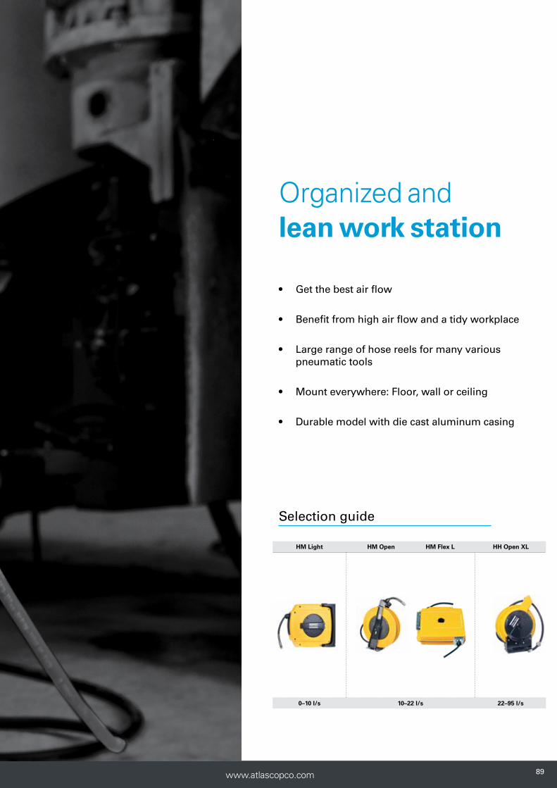
8989www.atlascopco.com
HM Light HM Open HM Flex L HH Open XL
0–10 l/s 10–22 l/s 22–95 l/s
Selection guide
Organized and lean work station
• Get the best air flow
• Benefit from high air flow and a tidy workplace
• Large range of hose reels for many various pneumatic tools
• Mount everywhere: Floor, wall or ceiling
• Durable model with die cast aluminum casing

909090 www.atlascopco.com
Hose reels
HM LIGHT Hose reels from the HM Light series have a robust design with a durable, high impact composite cas-ing. The outlet slot is optimized to provide an ideal pull-out angle for the hose. It is recommended to be used together with low air consuming tools such as small and medium screwdrivers, pulse tools, drills, impact wrenches, riveting and chipping hammers.
• Snap-on, pivoting wall bracket.• PVC/PUR hose.• Hose end provided with pressed fitting and steel
spiral hose protector.• Hose easily replaced when needed.• Drum with ball bearings on both sides.• Working temperature: 0°C - +50°C.• Inlet hose length: 1 m
Connection inlet Economical Max air flow Hose hose inside Connection air flow capacity Hose inside dia distribution (at 0.2 bar (at 0.5 bar length Hose dia (cut of hose) hose pressure drop) pressure drop) Weight Model m type mm in mm BSP ls ls kg Ordering No.
HM LIGHT 8-8 8 PVC/PUR 8 5/16 10 1/4 4 7 3 8202 1183 30a
HM LIGHT 8-12 12 PVC/PUR 8 5/16 10 1/4 3 5 5 8202 1183 31b
HM LIGHT 10-10 10 PVC/PUR 10 3/8 10 3/8 6 10 5 8202 1183 32b
a Working pressure: 12 barb Working pressure: 15 bar
Connection Hose Connection distribution Length inside dia inlet BSP hose BSP Air flow Weight Model m Hose mm in male male l/s kg Ordering No.
HM FLEX L 10 Rubber 12.5 1/2 1/2 1/2 22 16 8202 1181 56
HM FLEX L The HM FLEX L, with a steel casing and high quality rubber hose, handles both air and water. The HM FLEX L is recommended for all screwdriv-ers, pulse tools, impact wrenches, drills, chipping and riveting hammers and grinders up to 1,000 W.
• NBR rubber hose.• Movable brackets for floor, wall and
ceiling mounting.• High flow capacity.• Working temperature: -30°C - +60°C.• Max. working pressure: 15 bar.• Inlet hose length: 1 m.

9191www.atlascopco.com
Hose reels
HM OPEN The HM Open has an open composite casing, a steel frame with a 10 or 13 mm hose. It is a reliable, medium sized hose real recommended for screw-drivers, impact wrenches, pulse tools, drills, chip-ping and riveting hammers and grinders up 1,000 W.
• Spatter resistant rubber hose.
• Outlet roller posi-tion can be adjusted through 120 degrees for optimal pull-out angle.
• Hose end provided with steel spiral hose protector.
• Latch function is easily disengaged.
• Spring tension is easily adjusted.
• Floor, wall or ceiling mounting.
• Working temperature: -10°C - +60°C.
• Max. working pres-sure: 15 bar.
• Inlet hose length: 1 m.
Pivoting wall brackets needs to be ordered separately 4390 2080 10.
Connection inlet Economical Max air flow Hose hose inside Connection air flow capacity Hose inside dia distribution (at 0.2 bar (at 0.5 bar length Hose dia (cut of hose) hose pressure drop) pressure drop) Weight Model m type mm in mm BSP l/s l/s kg Ordering No.
HM OPEN 10-15 15 Rubber 10 3/8 12.5 3/8 5 9 11 8202 1183 33HM OPEN 10-20 20 Rubber 10 3/8 12.5 3/8 5 7 14 8202 1183 34HM OPEN 12-10 10 Rubber 12.5 1/2 12.5 1/2 13 22 12 8202 1183 35HM OPEN 12-15 15 Rubber 12.5 1/2 12.5 1/2 11 17 13 8202 1183 36
HM OPEN XL Hose reels in the HM Open XL series have an open die cast aluminum casing with a 3/8" or 1/2" hose. HM Open XL hose reels are recommended for screw- drivers, impact wrenches, pulse tools, drills, chipping and riveting hammers and high powered grinders.
• Spatter resistant rubber hose. • Floor, wall or ceiling mounting. • Revolving hinge for flexible use. • Working temperature: -10°C - +60°C. • Max. working pressure: 15 bar. • Inlet hose length: 1 m.
Pivoting wall brackets needs to be ordered separately 4390 2080 11.
Connection inlet Economical Max air flow Hose hose inside Connection air flow capacity Hose inside dia distribution (at 0.2 bar (at 0.5 bar length Hose dia (cut of hose) hose pressure drop) pressure drop) Weight Model m type mm in mm BSP l/s l/s kg Ordering No.
HM OPEN XL 12-20 20 Rubber 12.5 1/2 12.5 1/2 8 14 27 8202 1183 37HM OPEN XL 12-30 30 Rubber 12.5 1/2 12.5 1/2 8 12 28 8202 1183 38HM OPEN XL 19-15 15 Rubber 19 3/4 19 3/4 27 44 28 8202 1183 39HM OPEN XL 25-10 10 Rubber 25 1 25 1 60 95 30 8202 1183 40

929292 www.atlascopco.com
Working Air inlet pressure Air flow Weight thread Model Version bar l/s kg lb BSP Ordering No.
BG 2603-HF Long tube, high flow 6.3 7.5 0.13 0.29 1/4 8202 1006 04BG 2604-SHF Short tube 6.3 4.3 0.12 0.26 1/4 8202 1006 05BG 2605-STSS Short tube, star tip 6.3 6.6 0.12 0.26 1/4 8202 1006 06BG 2606-STS Long tube, star tip, silencer 6.3 6.3 0.14 0.31 1/4 8202 1006 07
Blow Gun BG-series Blow guns in the BG Series are a robust, user friendly solution for all cleaning applications. The plastic body offers flexibility in handling for both left and right handed users. It insulates against cold and reduces the risk of scratches to worksurfaces. The blow gun has excellent throttling properties al-lowing easy regulation of the air flow.
• High flow capacity• Suspension• Plastic body to avoid scratches• Air inlet thread in brass• Star tip availability for
improved safety• Applicable standards: OSHA STD1-13.1, OSHA
1910.95 (b).
Pressure control unitThe unit consists of a high quality pressure gauge and the necessary couplings for checking the air pressure at the air inlet of the machine.
Ordering No. 4145 0699 81.
Test Equipment
Blow guns and test equipement

9393www.atlascopco.com
All local safety regulations with respect to installation, operation and overhaul must always be followed. Please read the separate instructions regarding safety which are supplied with all products in order to improve your own safety!
Ball valvelSwitch off the compressed air with the ball valve when you
are not working (see fig. 1).lOpen all ball valves gently in order to discover improperly
tightened devices (see fig. 5).
Air preparation unitslPlease check for solvents which change the structure of poly-
carbonatea bowls.These solvents make the polycarbonate brittle so it can break. Normally polycarbonate is not easy to break. If you need to use aggressive solvents, please contact us and we will help you choose the right equipment.lUse bowl guard.An easy way to eliminate this type of accident is to use a bowl guard on MINI and MIDI units. The MAXI unit has an aluminum bowl with a new, more chemical resistant plastic on the inside as standard.
Check that the bowls are properly tightened and that all units are fitted together before switching on the compressed air with the ball valve.
Quick safety couplingsTo increase safety and reduce the risk of operator injuries we recommend you to always buy couplings with a safety function. Couplings with a safety function are disconnected in two stag-es in order to vent the coupling and minimize the risk of sudden component separation, which has the potential to cause opera-tor injury.
Never open a quick coupling with a screwdriver in order to ventilate the air.
Claw couplingslBe very careful (see fig. 1+2+3).They are always open and must be used very carefully. To in-crease safety when using claw couplings, we recommend the claw LNH claw coupling with a lock nut.
Clamps and connectionslAvoid screwdrivers when tightening.Check that they are properly tightened. Avoid screwdrivers when tightening, they can easily slip and damage your hand. Use a wrench. If you need to use a screwdriver, mount the clamp in a vice.
HosesWhen mounting hoses on hose connections, use water and soap in order to make the hose slip on to the connection.Do not use oil. Water and soap will dry up. Remove leaking hoses. A small leakage can quickly become a large hole.
Blow gunslUse the safety version. It eliminates the risk of air at high
pressure coming into direct contact with skin.a Polycarbonate has good chemical resistance to all solvents except chemicals
containing acetone, benzol, glycerine, some hydraulic and synthetic oils, chloroform, methyl alcohol, carbon tetrachloride (and similar solvents), carbon disulphide, perchloroethylene, toluene, trichloroethylene, xylene (nitrocellulose, thinner), acetic acid.
Follow this order when working with claw couplings.
How to open a claw coupling:Close the ball valve.
Run the tool so the air ventilates out.
Release the claw coupling. Open the ball valve gently.
How to close a claw coupling:Make sure that the two claw couplings are mounted together.Use claw couplings with lock nut (LNH) or use a lock spring for safer locking.
Product Safety
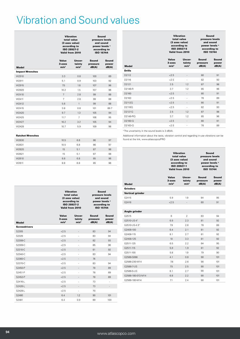
949494 www.atlascopco.com
Vibration and Sound values
Vibration total value
(3 axes value)according toISO 28927-2
Valid from 2010
Sound pressure levels
and sound power levels a
according toISO 15744
Value 3-axesm/s2
Uncer-taintym/s2
Sound pressure
dB(A)
Sound powerdB(A)Model
Screwdrivers
S2305 <2.5 - 83 94
S2326 <2.5 - 83 94
S2308-C <2.5 - 82 93
S2309-C <2.5 - 85 96
S2310-C <2.5 - 81 92
S2340-C <2.5 - 83 94
S2360-C <2.5 - 76
S2370-C <2.5 - 83 94
S2450-P <2.5 - 78 89
S2451-P <2.5 - 78 89
S2452-P <2.5 - 78 89
S2416-L <2.5 - 73 -
S2426-L <2.5 - 73 -
S2428-L <2.5 - 70
S2480 6.4 1.2 90 101
S2481 6.4 0.9 89 100
Vibration total value
(3 axes value)according toISO 28927-2
Valid from 2010
Sound pressure levels
and sound power levels a
according toISO 15744
Value 3-axesm/s2
Uncer-taintym/s2
Sound pressure
dB(A)
Sound powerdB(A) Model
Impact Wrenches
W2910 3.3 0.8 100 89
W2911 5.1 0.9 103 92
W2915 7.5 1.8 107 96
W2920 10.2 1.5 107 96
W2410 7 2.8 99 88
W2411 7 2.8 99 88
W2412 5.6 1 99 88
W2415 3.8 0.8 101 89.7
W2420 9.7 1.3 105 94
W2425 11.7 7 106 95
W2427 16.2 3.2 105 94
W2428 10.7 5.9 109 98
Ratchet Wrenches
W2630 10.5 6.8 86 97
W2631 10.5 6.8 86 97
W2620 15 5.1 87 98
W2621 15 5.1 87 98
W2610 8.8 6.8 85 96
W2611 8.8 6.8 85 96
Vibration total value
(3 axes value)according toISO 28927-5
Valid from 2010
Sound pressure levels
and sound power levels a
according toISO 15744
Value 3-axesm/s2
Uncer-taintym/s2
Sound pressure
dB(A)
Sound powerdB(A) Model
Drills
D2112 <2.5 - 80 91
D2116 <2.5 - 82 93
D2121 2.5 1.2 87 98
D2148-R 3.7 1.2 85 96
D2160 <2.5 - 80 91
D2163 <2.5 - 78 89
D2112Q <2.5 - 80 91
D2116Q <2.5 - 82 93
D2121Q 2.5 1.2 87 98
D2148-RQ 3.7 1.2 85 96
D2160-Q <2.5 - 80 91
D2163-Q <2.5 - 78 89
a The uncertainty in the sound levels is 3 dB(A).
Additional information about the tests, vibration control and regarding in-use vibrations can be found at the link, www.atlascopco/PRO
Vibration total value
(3 axes value)according toISO 28927-1
Valid from 2010
Sound pressure levels
and sound power levels a
according toISO 15744
Value 3-axesm/s2
Uncer-taintym/s2
Sound pressure
dB(A)
Sound powerdB(A) Model
Grinders
Vertical grinder
G2415 5.9 1.9 84 95
G2416 <2.5 - 80 91
Angle grinder
G2515 6 2 83 94
G2510-US-4" 6.9 2.3 81 92
G2510-US-4.5" 7.9 2.6 78 89
G2408-100 6.4 2.1 81 92
G2408-115 8.1 2.7 81 92
G2408-125 10 3.3 81 92
G2511-125 6.5 2.2 84 95
G2511-115 5,9 1,9 81 92
G2511-100 5.8 1.9 79 90
G2588-S066 4.1 0.8 90 101
G2588-230-M14 7.8 2.6 90 101
G2588-7-US 7.5 2.5 90 101 G2588-5-US 8.1 2.7 90 101 G2588-180-072-M14 6.8 2.2 90 101 G2588-180-M14 7.1 2.4 90 101

9595www.atlascopco.com
Vibration total value
(3 axes value)according toISO 28927-9
Valid from 2010
Sound pressure levels
and sound power levels a
according toISO 15744
Value 3-axesm/s2
Uncer-taintym/s2
Sound pressure
dB(A)
Sound powerdB(A) Model
Percussive
P2520 17 3.2 78 -
P2540 3.4 0.8 83 94
P2541 3.1 0.8 85 96
P2550 5.3 1.7 83 94
P2551 6.7 2.8 85 96
P2505 5.6 1 72 -
P2530-H 12.5 4.8 96 107
P2530-R 12.5 4.8 96 107
P2531-H 11.5 4.7 100 107
P2531-R 11.5 4.7 100 107
P2535-H - - 103 114
P2535-R - - 103 114
P2536-H - - 103 114
P2539-H - - 102 113
Vibration total value
(3 axes value)according toISO 28927-8
Valid from 2010
Sound pressure levels
and sound power levels a
according toISO 15744
Value 3-axesm/s2
Uncer-taintym/s2
Sound pressure
dB(A)
Sound powerdB(A) Model
Saw
C1050 14 2.3 78 89
Vibration total value
(3 axes value)according toISO 28927-12
Valid from 2010
Sound pressure levels
and sound power levels a
according toISO 15744
Value 3-axesm/s2
Uncer-taintym/s2
Sound pressure
dB(A)
Sound powerdB(A) Model
Grinders
Die grinder
G2412-1 <2.5 - 79 90
G2440 <2.5 - 80 91
G2445 4.3 1 90 101
G2414-S085 <2.5 - 70 -
G2414-S120 <2.5 - 74 -
G2414-S150 2.5 0.7 76 -
G2414-S200 <2.5 - 81 92
G2414-S250 <2.5 - 85 96
G2414 S088-US <2.5 - 71 -
G2414 S125-US <2.5 - 74 -
G2414 S155-US 2.5 0.7 77 -
G2414 S205-US <2.5 - 81 92
G2414 S255-US <2.5 - 87 98
G2422-1 3.4 0.8 77 -
G2424-S085 5.3 1.2 <70 -
G2424-S120 <2.5 - 73 -
G2424-S150 <2.5 - 76 -
G2424-S200 <2.5 - 81 92
G2424-S250 3.5 0.8 85 96
G2424 S088-US 5.3 1.2 <70 -
G2424 S125-US <2.5 - 73 -
G2424 S155-US <2.5 - 76 -
G2424 S205-US <2.5 - 81 92
G2424 S255-US 3.5 0.8 85 96
G2417-S250 <2.5 - 81 92
G2417-S180 4 0.9 74 -
G2417-S120 <2.5 - <70 -
G2417-S250-US <2.5 - 81 92
G2417-S180-US 4 0.9 74 -
G2417-S120-US <2.5 - <70 -
G2427-S250 <2.5 - 81 92
G2427-S180 3.8 1.9 74 -
G2427-S120 5.8 1.2 <70 -
G2427-S250-US <2.5 - 81 92
G2427-S180-US 3.8 1.9 74 -
G2427-S120-US 5.8 1.2 <70 -
G2451 2.9 1.4 79 -
Vibration total value
(3 axes value)according toISO 28927-3
Valid from 2010
Sound pressure levels
and sound power levels a
according toISO 15744
Value 3-axesm/s2
Uncer-taintym/s2
Sound pressure
dB(A)
Sound powerdB(A) Model
Sanding and polishing
G2588-S085-M14 2.8 0.7 90 101
G2588-S066-US 4.1 0.8 90 101
G2588-S085-US 4.2 0.8 90 101
G2410 <2.5 - 89 100
G2420 <2.5 - 83 94
G2302 <2.5 <2.5 81 92
G2502 <2.5 - 84 95
G2406 <2.5 - 79 -
G2407 <2.5 - 79 -
G2407M14 <2.5 - 79 -
G2438-6.3N 3.7 1.7 84 95
G2438-6.5N 10.5 4.5 85 96
G2438-6.10N 6.9 3.1 87 98
G2438-6.3I 3.7 1.7 84 95
G2438-6.5I 10.5 4.5 85 96
G2438-6.10I 6.9 3.1 87 98
G2438-6.3C 3.7 1.7 84 95
G2438-6.5C 10.5 4.5 85 96
G2438-6.10C 6.9 3.1 87 98
G2428 6.8 3.2 87 98
a The uncertainty in the sound levels is 3 dB(A).
Additional information about the tests, vibration control and regarding in-use vibrations can be found at the link, www.atlascopco/com/PRO


9833
846
4 01
201
8:1
www.atlascopco.com