Embed Size (px)
Citation preview

F10DA11000 Series

Table of Contents
F10DA BOM……..………………………………………………………… 1
F10DA Sub Assy. Instruction Manual...………..……………………….. 12
F10DA System setup instruction manual………………………………. 24
F10DA 10.6"LCD Instruction Manual….……………………………….. 42
F10DA Disassembly…………..………………………………………….. 55

01-0075KE-J0 CPU-CELERON M DOTHAN ULV-1.0GHZ-uFC-BGA 4-RJ80536VC001512 SL8A4(868320)-0.956V-512K-01-0077K8-J0 CPU-PENTIUM M DOTHAN ULV-1.1GHZ/600MHZ-uFC-BGA 4-RJ80536UC0052M SL7F4(860555)-0.956V-01-0077K7-J0 CPU-PENTIUM M DOTHAN ULV-1.2GHZ/600MHZ-uFC-BGA 4-RJ80536UC0092M SL89Z(868317)-0.956V-
02-A85502-G0 CHIPSET-855GME-732P FCBGA-GMCH02-A85500-G0 CHIPSET-855GM-732P FCBGA-GMCH02-A82801-A1 CHIPSET-82801DBM-421P BGA-ICH4-M
05-49004C-21 PMC Flash ROM PM49FL004T-33JC02-C60114-90 AUDIO AMPLIFILER-TPA6011A4PWP-5V02-E71120-A0 PCMCIA CARDBUS CONTROLLER-OZ711MP1B-184P MINI BGA03-C65500-80 AUDIO CODEC-ALC655-LQFP48-SIX CH03-A95081-90 CLK GEN.-ICS950812-56P TSSOP03-B38857-81 K/B controller-Micro Processor-up-M38857M8-A10HP-3.3V+-0.3V-8MHZ-LQFP 8008-C17370-30 BATTERY CHARGER IC-MAX1737EEI-28
18-060005-MO DDR SO-DIMM-HYMD232M646D6-J-256MB-DDR333-2.5V+/-0.2V-200P-HYNIX18-060005-L0 DDR SO-DIMM-M2S5I08D6APS5F081AA-T-256MB-DDR333-2.5V+/-0.1V-200P-IC:A2S56D30BTP-6-18-060006-D0 DDR SDRAM SO-DIMM-ADFDB290800H-512MB-DDR333-2.5V+-0.2V-200P-ON A-DATA IC-A-DATA18-060006-C0 DDR SO-DIMM-M2S5J08D1AHX5F1611C-T-512MB-DDR333-2.5V+/-0.1V-200P-TWINMOS18-060007-20 DDR SO-DIMM-HYMD512M646BF8-J-1GB-DDR333-2.5V+/-0.2V-200PIN-HYNIX
82-8A1230-00C F10DA-PCB ASS'Y-GU-PM-REV:C w/ULV Dothan 1.1GHz, 855GME & BIOS set, TRI CSG80-A12100-00A F10DA-PCB ASS'Y-GU-DC-IN-REV:A80-8A1220-00C F10DA-PCB ASS'Y-GU-3-in-1-REV:C80-8A1200-00A F10DA-PCB ASS'Y-GU-Instant on-REV:A80-8A1200-00A F10DA-PCB ASS'Y-GU-Power bottom-REV:A86-677000-00 #8160/8162-M System cabinet
72-11023J-00 LCD-10.6" TFT WXGA-SHARP-LQ106K1LA01A72-11026S-00 LCD-10.6" TFT WXGA-SAMSUNG-LTN106W2-L01
70-922401-30 Hitachi 40GB, 9.5mm, HTS424040M9AT00, 4200rpm, TRIGEM CSG70-A22601-00 Hitachi 60GB, 9.5mm, IC25N060ATMR04, 4200rpm, TRIGEM CSG
LCD 10.6"WXGA TFT
CPU
North/SouthBridge Chip
Core logical chip
DDR Module(333MHz)
PCBA_W/BIOS
F10DA1 Series Keyparts List for Averatec R:D
Item TIC P/N Description
1

F10DA1 Series Keyparts List for Averatec R:D
Item TIC P/N Description
70-B22800-00 Hitachi 80GB, 9.5mm, IC25N080ATMR04, 4200rpm, TRIGEM CSG70-A22602-00 HDD-60GB-4200RPM-ST960821A-SEAGATE70-B22803-00 HDD-80GB-4200RPM-ST9808210A-SEAGATE70-922405-00 HDD-40GB-5400RPM-WD400UE-WD70-A22605-00 HDD-60GB-5400RPM-WD600UE-WD70-B22805-00 HDD-80GB-5400RPM-WD800UE-WD
70-210027-00 QSI Ultra Slim Combo drive 9.5mm, UBW-241( 8x \ 24x24x24 )70-210031-00 HITACHI-LG Ultra Slim Combo drive 9.5mm, -GCC-4242N-
71-836101-00 K/B-83 KEY-EN-11015# WHITE-F10DA1-K022309A1 US-JME71+836133+00 K/B-83 KEY-EN-11015# WHITE-F10DA1-K022309A1 CH-JME71+836104+00 K/B-83 KEY-EN-11015# WHITE-F10DA1-K022309A1 KR-JME71+836129+00 K/B-83 KEY-EN-11015# WHITE-F10DA1-K022309A1 CF-JME71+836105+00 K/B-83 KEY-EN-11015# WHITE-F10DA1-K022309A1 FR-JME71+836108+00 K/B-83 KEY-EN-11015# WHITE-F10DA1-K022309A1 UK-JME71+836107+00 K/B-83 KEY-EN-11015# WHITE-F10DA1-K022309A1 GR-JME
23-050250-00 BAT-LIION-3S2P-2000mAh-#8162-PS-0292TWF10D191G-SAMSUNG CELL-F10DA1-E1118-0823-050251-00 BAT-LIION-3S2P-2000mAh-#8162-SMP-F10DA1-E1118-0923-050252-00 BAT-LIION-3S2P-2200mAh-#8162-PS-0292TWF10D291G-SAMSUNG CELL-F10DA1-E1118-0823-050253-00 BAT-LIION-3S2P-2400mAh-#8162-PS-0292TWF10D311G-SAMSUNG CELL-F10DA1-E1118-08
76-060009-00 MDC MODEM CARD-12mA-3.3V-39.6mW-W/MOTO CHIPSET-QCOM-ML3054
76-010599-00 ADAPTER-3.42A-19V-65W-WHITE-2PIN-LITEON-PA-1650-01AV29-020340-00 US pwt ( 2 pin ) white29+020341+00 TW pwt ( 2 pin ) white29+020345+00 UK pwt ( 2 pin ) white29+020342+00 GR/FR/SP pwt ( 2 pin ) white29+020344+00 China pwt ( 2 pin ) white29+020343+00 Korea pwt ( 2 pin ) white29+020346+00 JP pwt ( 2 pin ) white
HDD
9.5mm ODD
K/B
Battery
Modem
colorful adapter& power core
2

F10DA1 Series Keyparts List for Averatec R:D
Item TIC P/N Description
76-030105-30 Sumida Inverter-5V-IV10123/T-TWS-450-096-E12K
73-080101-00 TOUCH PAD UNDER PLASTIC 0.8mm-67x40x0.85mm-ELANTECH-800409-5303-F10DA1
76-070024-01 WLAN MODULE MINIPCI-3.3V-TYPE 3B-IEEE 802.11b/g-INTEL-WM3B2200BGRW3(862236), for EU market76-070034-00 WLAN MODULE MINIPCI-3.3V-TYPE 3B-IEEE 802.11b/g-INTEL-WM3B2200BGMW2, for US market76-070029-10 WLAN MODULE MINI PCI-3.3V-802.11b/g RALINK TYPE 3B-MSI-MS-6833A76-080025-00 WLAN MODULE MINI PCI-3.3V-802.11b/g RALINK TYPE 3B-MSI with Bluetooth-MS-6855B
Inverter
Touch pad
WLAN & Antenna
3

1000 Series (F10DA) system Base kit for US model ==========================================================================Items ITEM NUMBER DESCRIPTION QTY
==========================================================================A.
Main board without Instant On fuction
82-8A1290-00C F10DA1-PCB ASS'Y-GU-PM-REV:C-P-M DOTHAN ULV1.1G/855GME-TRI CSG W/BIOS SET 1
80-8A1200-00A F10DA1-PCB ASS'Y-GU-POWER BOTTOM-REV:A 280-8A1220-00C F10DA1-PCB ASS'Y-GU-3 IN 1-REV:C 180-A12100-00A F10DA1-PCB ASS'Y-GU-DC IN-REV:A 1
B.22-600154-00 WLAN W/CABLE-F4371-F10DA1 129-005364-00 F10DA1-RJ11/RJ45 CABLE-CA364 129-005367-00 F10DA1-CABLE FOR DC IN-CA367 129-015359-00 F10DA-FPC GU-ODDCON-CONNECTS ODD 129-016363-00 F10DA1-FFC FOR TOUCHPAD-CA363 140-003650-00 F10DA1-HEATSINK W/FAN-F4218 141+720516+04 SCREW ISOT-M1.6X4L,∮D3.0,H0.8-N 241-720530-04 SCREW ISOT (LCD COVER)-M3X4L ∮5 441-721120-04 SCREW ISOT-M2X4L-NI ∮D=3.5mm t= 341-722526-05 SCREW ISOT-M2.6X5L,∮D4.5,H0.8-N 441-725120-03 SCREW ISOT-M2X3L,∮D3.0,H0.4-NI- 541-760520-08 SCREW ISOTT-M2X8L,∮D4.0,H0.8-SE 644-000001-00 PROCESS MATERIALS FOR SYSTEM 161-015000-00 PROTECTION SHEET FOR LCD-36CM*50 950+023639+00 F10DA1-MYLAR FOR MB-F4318 151+035090+00 F10DA1-GASKET FOR VGA PORT-F4373 151+036301+00 F10DA1-HDD SPONGE-30X8X4mm-BLACK 151-350094-08 CONDUCTIVE SPONGE 10X10.5X1000-K 4
1000 Series (F10DA) PCBA for all models
Daughter board with DC-IN, Power button & 3-in-1 of PCBA
1000 Series (F10DA)-#8160/#8162-M SYSTEM CABINET
4

1000 Series (F10DA) system Base kit for US model ==========================================================================Items ITEM NUMBER DESCRIPTION QTY
==========================================================================52+002422+01 F10DA1-RUBBER FOR LOWER COVER-F4 152-000110-00 F10DA1-RUBBER FOOT OF THE FRONT- 252-000111-00 F10DA1-RUBBER FOOT OF THE REAR-P 252-002423-00 F10DA1-RUBBER FOR LOWER COVER-LE 1
C.22-300130-00 SPEAKER W/CABLE-F4257-F10DA1 1
41+810D02+45 SCREW ISOF-M2X4.5L-∮D3.8,H1.2- 141-721120-03 SCREW ISOT-M2X3L-NI ∮D3.5mm t=0 850-967701-21 F10DA1-#8160 UPPER COVER ASS'Y-E 150-967701-30 F10DA1-#8160 SPEAKER COVER ASS'Y 150-967701-40 F10DA1-#8160 TOUCH PAD BUTTON AS 151-005080-00 F10DA1-NON WOVEN FOR SPEAKER COV 173-080101-00 TOUCH PAD UNDER PLASTIC 0.8mm-67 1
D.40-002522-00 F10DA1-LOWER COVER-#8162-M-B1377 140-012090-00 F10DA1-SPRING FOR BATTERY LOCK-F 150-023638-00 F10DA1-LOWER COVER MYLAR FOR HDD 150-041120-00 F10DA1-BATTERY LOCK KNOB-#8162-F 250-041121-00 F10DA1-WIRELESS KNOB-#8162-F4232 150-043101-00 F10DA1-BATTERY LATCH-R-F4234 150-043102-00 F10DA1-BATTERY LATCH-L-F4233 150-967701-50 F10DA1-#8162 I/O DOOR ASS'Y-E111 1
E.50-050200-10 F10DA1-LED NAME PLATE-W/O BLUETOOTH 1
63+040280+20 F10DA1-FCC RATING LABEL-EN 163-250190-00 KEY PARTS BARCODE LABEL-KL18260 1
76-070034-00TRIWLAN MODULE MINIPCI-3.3V-TYPE 3B 1
1000 Series (F10DA)-#8162-M LOWER COVER KIT
1000 Series (F10DA) Intel WLAN KIT
1000 Series (F10DA) #8160 UPPER COVER KIT
5

1000 Series (F10DA) system Base kit for US model ==========================================================================Items ITEM NUMBER DESCRIPTION QTY
==========================================================================F.
50-050200-10 F10DA1-LED NAME PLATE-W/O BLUETOOTH 163+040280+20 F10DA1-FCC RATING LABEL-EN 163-250190-00 KEY PARTS BARCODE LABEL-KL18260 176-070029-00 WLAN MODULE MINI PCI-3.3V-802.11 1
1000 Series (F10DA) MSI WLAN KIT
6

1000 Series (F10DA) system LCD kit for all models ===================================================================Items ITEM NUMBER DESCRIPTION QTY
===================================================================A.
86-677H05-30 #8466-M/#8160 DISPLAY ASS'Y-10.6 122-600150-00 F10DA1-ANTENNA-R-D3057 122-600151-00 F10DA1-ANTENNA-L-D3058 163-250190-00 KEY PARTS BARCODE LABEL-KL18260 272-11026S-00 LCD-10.6" TFT WXGA-SAMSUNG-LTN10 176-030117-00 INVERTER-5V-SUMIDA-IV10123/T F10 127-600050-00 F10DA1-MAGNET-F4247 129-001773-01 F10DA1-HARNESS FOR SAMSUNG LCD-S 140-015140-01 F10DA1-HINGE-R-D3050 140-015141-01 F10DA1-HINGE-L-D3049 140-031653-00 F10DA1-LCD BRACKET-L FOR SAMSUAN 140-031654-00 F10DA1-LCD BRACKET-R FOR SAMSUAN 140-967701-82 F10DA1-#8466-M LCD COVER ASS'Y-F 141-720526-03 SCREW ISOT-M2.6X3L-SELF-LOCKING- 441-761520-04 ISOTT SCREW-M2X4L,∮D3.5mm,H-0.5 1250-023633-00 F10DA1-MYLAR FOR HINGE-L-F4250 150-023634-00 F10DA1-MYLAR FOR HINGE-R-F4249 150-023635-00 F10DA1-MYLAR FOR PANEAL-F4251 250-034120-00 F10DA1-LCD PANEL-#8160-B1380 150-035294-01 F10DA1-COVER FOR LCD HINGE-R-#81 150-035295-00 F10DA1-COVER FOR LCD HINGE-L-#81 151-036300-00 F10DA1-LCD SPONGE-FOR MAGENTIC-F 152-002420-00 F10DA1-RUBBER FOR LCD PANEL-WHIT 252-002421-00 F10DA1-LCD RUBBER-WHITE-F4238 1
#8466-M/#8160 Samsung display ASS'Y-10.6" WXGA TFT
7

==================== =============================================Items ITEM NUMBER DESCRIPTION QTY
==================== =============================================A.
40-031650-00 F10DA1-ODD BRACKET-R-F4220 140-031651-00 F10DA1-ODD BRACKET-L-F4221 141+760512+03 SCREW ISOTT-M1.2X3L,∮D3.0,H0.3- 241-760920-02 SCREW-ISOTT-M2X2L-∮D3.0,H0.5-BL 450-000483-00 F10DA1-QUANTA COMBO TRANSFER BEZ 150-023637-00 F10DA1-MYLAR FOR ODD BRACKET LEF 150-967701-61 F10DA1-#8162 COMBO BEZEL ASS'Y-F 1
B.40-031650-00 F10DA1-ODD BRACKET-R-F4220 140-031651-00 F10DA1-ODD BRACKET-L-F4221 141+760512+03 SCREW ISOTT-M1.2X3L,∮D3.0,H0.3- 241-760920-02 SCREW-ISOTT-M2X2L-∮D3.0,H0.5-BL 450+000485+00 F10DA1-HLDS COMBO TRANSFER BEZEL 150+967701+71 F10DA1-#8162 COMBO BEZEL ASS'Y-F 150-023637-00 F10DA1-MYLAR FOR ODD BRACKET LEF 1
3260 Series (E12KA) system for all models Disk kit
QSI F10DA1-#8162 COMBO drive Kit
HLDS F10DA1-#8162 COMBO drive Kit
8

3260 Series (E12KA) system for all models Labels kit ==========================================================================Items ITEM NUMBER DESCRIPTION QTY
==========================================================================A.
63+070101+40 F10DA1-POP STICKER-RIGHT-EN-RELE 163+070103+40 F10DA1-TECHNICAL SPECIFICATIONS 263-000756-00 N222S8L-BLANK LABEL-E43960-50X13 1
Parts kit for AI-AV1050EB1-US model
9

1000 Series (F10DA) system Packing kit for all models ====================================================================Items ITEM NUMBER DESCRIPTION QTY
====================================================================A.
50+000487+00 F10DA1-DUMMY CARD-WHITE 160-010001-00 PE BAG 70X120mm 160-010070-00 PLASTIC BAG-35cmX25cm-FOR CD/MAN 163+070100+00 F10DA1-VOID LABEL-EN 163-001262-00 E12T-BLANK LABEL FOR SHIPPING-21 163-001882-00 E12T-BOX SEAL STICKER-FOR AVERAT 264-000501-00 SILICA GEL 5g 127+309030+10 TRANSPARENT PE PROTECTIVE FILM 050+000486+00 F10DA1-PLASTIC HANDLE-D30950 160-010067-00 PE-BAG-400X300mm-B4752A-P79S-PE 160-012002-00 ANTI-STATIC BAG 110*290 161+007321+00 F10DA1-1 IN 1 PAPER CUSHION FOR 161+011020+11 F10DA1-PALLET FOR AVERATEC-E4361 0.0461+015120+00 F10DA1-PROTECTION SHEET FOR K/B- 161+120177+10 F10DA1-ANGLE PROTECTOR-76X76X360 0.1761+967701+J0 F10DA1-1 IN 1 R PAPER CUSHION AS 161+967701+K0 F10DA1-1 IN 1 L PAPER CUSHION AS 161-000844-00 PE STRAP 0.6261-009010-00 ALL MODEL-ANGLE PROTECTOR-KL1888 0.0861-012415-30 E12B-PALLET UP DOWN PAPER BOARD- 0.0861-097608-00 ANGLE PROTECTOR 76X76X800mm-KL14 0.08
B.
62+009350+00 QUICK START GUIDE-EN-R1.00-F10DA 162+090401+20 CD NOTICE FOR HDD RECOVERY-EN-R1 161+004140+00 F10DA1-1 IN 1 COLOR BOX-D30940 1
The common parts be used in packing kit
The Unigue parts for each model1 IN 1 PACKING for AV1050-EB1US model
10

1000 Series (F10DA) system Power kit for all models ============================================================================Items ITEM NUMBER DESCRIPTION QTY
============================================================================A.
23-050250-00 #8162 BAT-LIION-3S2P-2000mAh-PST-SAMSUNG Cell 163-250190-00 KEY PARTS BARCODE LABEL-KL18260 1
B.76-010599-00 01AV 129-020340-00 US pwt ( 2 pin ) white 129+020345+00 UK pwt ( 2 pin ) white 129+020342+00 GR/FR/SP pwt ( 2 pin ) white 129+020343+00 Korea pwt ( 2 pin ) white 1
ADAPTER & Power Cord kits
PST #8162 LI-ION BATTERY ASS'Y
11

Tw inhead International (Kunshan) CO.,LTD
REVISION: 0
PREPARED BY CONCURREDBY APPROVED BY
1.NEW RELEASE PE: Li Shin Prepared by:
2005.04.16
QC﹕
DOCUMENT CODE:TESOP585
RELEASE DATE:
PAGE: 11 (total 12 pages)
DESCRIPTION
Tw inhead
F10 DA Sub-Assembly SOP
12

Page No. and Rev. No. List:Page No. Rev. No. Page No. Rev. No. Page No. Rev. No. Page No.Rev. No.
1. Table of Contents P.01 1 0 2. Machine Assembly Material List/Operation Instructions/Figures P.2~P.11 2 0
3 0 1. 6501 Upper Cover Assembly Diagram (4 persons) P.02 ~P.05 4 0 2. 6402 Lower Cover Assembly Diagram(3 persons) P.06 ~ P.08 5 0 3. 6504 ODD Assembly Diagram (2 persons) P.09~ P.10 6 0 4. 6506 HDD Assembly Diagram (1 person) P.11 7 0
8 0 3. Tools: Tape stand, electrical screwdriver, bamboo chopsticks. 9 0
10 011 0
PAGE:01
(Document NO.):TESOP585
REV: 0
Shown in BOM are details of actual materials used.
This SOP is applicable for the F10DA Sub-Assembly Operation
F10DA Sub-Assembly SOPTable of Contents for F10DA Sub-Assembly SOP
Tw inhead International (Kunshan) CO.,LTDTw inhead
13

(Manufacturing Section):PWorking name:6501-1 Revision:0 Date : 2005.04.15
Difference Operating Item Part name / Specification Parts Number Q'TY Operation Description Important Note
1 F10DA1-#8160 UPPER COVERASS'Y-E1188-06 50-967701-22 1 Make sure the Upper Cover is free of defects such as
scratch, bruise, stains or deformation, etc.
UPPER COVER The liroplate at the bottom right sh
attach to the Upper Covesecurely.
2TOUCH PAD UNDER PLASTIC0.8mm-67x40x0.85mm-ELANTECH-800409-5303-F10DA1
73-080101-00 1 NA
3 MYLAR NA 1 NA
4 Month label 63-000042-XX 1 NA
5 PROTECTION SHEET FOR LCD-36CM*500M (LCD protection film) 61-015000-00 2 Stick the protection film on the upper part of touch pad
below the Upper Cover. NA
Explanation for illustration
PAGE: 02
Check the appearance of Touch Pad, and then stick onepiece of Mylar onto the Touch Pad and then attach themonth label on the Touch Pad at the position shown in thefigure.
( Twinhead S.O.P ) ( Document NO):TESOP585
Name of S.O.P:F10DA UPPER COVER SOP
Tw inhead International (Kunshan) CO.,LTDTw inhead
3
1
4 2
The bracket melting point shouldnot protrude. The magnet shouldattach securely on the UpperCover without gap left in-between.
14

(Manufacturing Section):PEWorking name:6501-2 Revision:0 Date : 2005.04.15
Difference Operating Item Part name / Specification Parts Number Q'TY Operation Description Important Note Jig / Fixture
1TOUCH PAD UNDER PLASTIC0.8mm-67x40x0.85mm-ELANTE CH-800409-5303-F10DA1
73-080101-00 1Check the appearance of Touch Pad. After stripping theback-glue paper, assemble it on the position of Upper Coveras per the figure.
NA NA
2 F10DA1-FCC FOR TOUCHPAD-CA363 29-016363-00 1 Insert the harness into the receiving port of Touch Pad
securely. NA NA
3 F10DA1-#8160 TOUCH PADBUTTON ASS'Y-E1118-07 50-967701-41 1 NA NA
4 SCREW ISOT-M2X3L-SELF-LOCKINGD3.5mm t=0.8mm-B4424H 41-721520-03 3 NA
ElectricalScrewdriver/Torque: 1.5
± 0.2Kgf-cm
5 F10DA1-TOUCH PAD MYLAR-F4393 50+023671+00 1
Penetrat the Touch Pad harness through the hole at thcenter of Mylar and then attach the Mylar in the slot ofTouch Pad, with the lower part bonded on the support framealong the folding line
Be square without floating. NA
6 ALL MODEL-INSULATING TAPE-10mmX66m,T=0.5mm 27-309090-00 1 Arrange the wires and fix thme with a tape, as per the figure. NA Tape stand
Make sure the appearance of Touch Pad Button is free ofdeformation. Push it into the upper slot for assembling onthe Touch Pad, and then lock the screws in place as per thefigure.
PAGE: 03
( Twinhead S.O.P ) ( Document NO):TESOP585
Name of S.O.P:F10DA UPPER COVER SOP
Explanation for illustration
Tw inhead International (Kunshan) CO.,LTDTw inhead
24
1 6
53 Trim the FFC harness in the hole.
The surface of these two parts mustbe smooth withuot any protrusion.
15

(Manufacturing Section) : PEWorking name:6501-3 Revision:0 Date : 2005.04.15
Difference Operating Item Part name / Specification Parts Number Q'TY Operation Description Important Note Jig / Fixture
1 SPEAKER W/CABLE-F4257-F10DA1 22-300130-00 1Strip the back-glue paper below the speaker and thenposition the speaker on the Upper Cover at theposition shown as per the figure.
Push the upper part into thelatch of Upper Cover. NA
2 NA NA NA Penetrate the speaker wires through the right-side holeand arrange as per the figure.
The wires must be insertedinto the positioning pole
without lifting.NA
3 Acetic tape (approx. 3cm long) NA 4 Shown as per the figure, arrange the wires by fixingthem with four pieces of acetic tapes.
Wires should be arrangedtrimly in side-by-side manner
without lifting.NA
( Twinhead S.O.P ) ( Document NO):TESOP585
Explanation for illustrationName of S.O.P:F10DA UPPER COVER SOP
Tw inhead International (Kunshan) CO.,LTDTw inhead
2
34
The speaker wires should be fully inserted in the latch side-by-side.
The speaker wire should beaway from the screw holehere
The wire trimmed on the left side should evade the K/Blatch on the right side, and do not attach the tape on thewhite latch, either.
16

(Manufacturing Section):PEWorking name:6501-4 Revision:0 Date : 2005.04.15
Difference Operating Item Part name / Specification Parts Number Q'TY Operation Description Important Note Jig / Fixture
1F10DA1-PCB ASS'Y-GU-POWERBOTTOM-REV:A-W/MECHANICALPARTS KIT
80-8A1200-00A 1Fix the Power Bottom PCB at the upper left corner ofthe Upper Cover and then arrange wires in the positionas per the figure.
NA NA
2F10DA1-PCB ASS'Y-GU-POWERBOTTOM-REV:A-W/MECHANICALPARTS KIT
80-8A1200-00A 1Fix the Power Bottom PCB at the upper right corner ofthe Upper Cover and then arrange wires in the positionas per the figure.
NA NA
3 SCREW ISOT-M2X3L-SELF-LOCKINGD3.5mmt=0.8mm-B4424H 41-721520-03 2 Lock the screws to fix the left and right Power PCBs as
per the figure. NA Electrical
Screwdriver/Torque:1.5 ± 0.2Kgf-cm
4 NA NA 1Check the appearance of the Upper Cover, and then putthe Upper Cover in the protection bag for loading in thecarton.
NA NA
Explanation for illustration
PAGE: 05
( Twinhead S.O.P ) ( Document NO):TESOP585
Name of S.O.P:F10DA UPPER COVER SOP
Tw inhead International (Kunshan) CO.,LTDTw inhead
1
1
2
33
17

(Manufacturing Section) : PERevision:0 Date : 2005.04.15
Difference Operating Item Part name / Specification Parts Number Q'TY Operation Description Important Note Jig / Fixture
1 F10DA1-LOWER COVER-#8162-M-B1377 40-002522-01 1 Make sure the appearance of Lower Cover is free of stains
Do not take the left side PCMCIA andODD assembly cross beam and battery
slot with hand or press with force,which shall be free of deformation and
breaking.
NA
2 F10DA1-BATTERY LATCH-L-F4233 50-043102-00 1
Check that the appearance of the left-side Battery Latch isnot deformed, and then install the Battery Latch on thebase plate as per the figure.
NA NA
3 F10DA1-RUBBER FOOT OF THEREAR-PANTONE 428C-F4236 52-000111-00 2 Attach the food pad as per the figure. NA
4 F10DA1-RUBBER FOOT OF THEFRONT-PANTONE 428C-F4235 52-000110-00 2 Attach the food pad as per the figure. NA
PAGE : 06
Explanation for illustration
( Twinhead S.O.P ) ( Document NO):TESOP585
Name of S.O.P:F10DA LOWER COVER SOP Working name : 6502-1
Be square without floating.
Tw inhead International (Kunshan) CO.,LTDTw inhead
42
3
1
18

(Manufacturing Section):PERevision:0 Date : 2005.04.15
Difference Operating Item Part name / Specification Parts Number Q'TY Operation Description Important Note Jig / Fixture
1 F10DA1-BATTERY LATCH-R-F4234 50-043101-00 1
2 F10DA1-SPRING FOR BATTERY LOCK-F4256 40-012090-00 1
3 F10DA1-BATTERY LOCK KNOB-#8162-F4231 50-041120-01 2 Assemble two battery latches for fixing the battery
Lock Knobs, as per the figure.
After assembly, check that theleft and right sliding must besmooth without loosening.
NA
( Twinhead S.O.P ) ( Document NO):TESOP585
Name of S.O.P:F10DA LOWER COVER SOP Working name : 6502-2
Do not deviate the right sideof the spring.
Explanation for illustration
PAGE: 07
Assemble the spring onto the Battery Latch, and theninstalled them on the base plate together. NA
Tw inhead International (Kunshan) CO.,LTDTw inhead
213 The sliding action
must be smooth
Do not deviate this side of the spring as toexceed the right side of the slot.
The sliding actionmust be smooth.
19

(Manufacturing Section) : PERevision:0 Date : 2005.04.15
Difference Operating Item Part name / Specification Parts Number Q'TY Operation Description Important Note Jig / Fixture
1 F10DA1-LOWER COVER MYLAR FORHDD-F4255 50+023638+02 1 Attach one piece of Mylar onto the base, as per the
figure. The Mylar opening shall align with
the screw hole of the base. NA
2 F10DA1-#8162 I/O DOOR ASS'Y-E1118-04 50-967701-51 1 Assemble the I/O Door onto the base, as per thefigure.
The right side of I/O Door must befixed by the positioning pole withoutloosening, and check that the rubber
latch can be latched on the base.
NA
3 NA NA 1After checking the appearance, place the LowerCover in the protection bag and then load in thecarton.
NA NA
Explanation for illustration
PAGE: 08
( Twinhead S.O.P ) ( Document NO):TESOP585
Name of S.O.P:F10DA LOWER COVER SOP Working name : 6502-3
Tw inhead International (Kunshan) CO.,LTDTw inhead
2 1
20

(Manufacturing Section) : PERevision:0 Date : 2005.04.15
Difference Operating Item Part name / Specification Parts Number Q'TY Operation Description Important Note Jig / Fixture
COMBO(CD-ROM/CD-RW/DVD-ROM)-UBW-241-QUANTA 70-210027-00
COMBO(CD-ROM/CD-RW/DVD-ROM)-UBW-241G-QUANTA 70-210028-00
COMBO(CD-ROM/CD-RW/DVD-ROM)-UBW-241-TRIGEM CSG-QUANTA
70-210027-00TRI
COMBO(CD-ROM/CD-RW/DVD-ROM)-128X12.7X129mm-GCC-4243N-TRIGEM CSG-HITACHI-LG
70-210030-00TRI
COMBO(CD-ROM/CD-RW/DVD-ROM)-9.5mm-GCC-4242N-HITACHI-LG
70-210031-00
2 F10DA1-ODD BRACKET-L-F4221 40-031651-00 1 NA U-shape locking supportedjig.
3 SCREW-ISOTT-M2X2L-∮D3.0,H0.5-BLACK-SELF-LOCKING-B3516
41-760920-02 2 NAElectricalScrewdriver/Torque: 1.0±0.2Kgf-cm
4 F10DA1-ODD BRACKET-R-F4220 40-031650-00 1 NA U-shape locking supportedjig.
5 SCREW-ISOTT-M2X2L-∮D3.0,H0.5-BLACK-SELF-LOCKING-B3516
41-760920-02 2 NAElectricalScrewdriver/Torque: 1.0±0.2Kgf-cm
6 KEY PARTS BARCODE LABEL-KL18260 63-250190-00 1 Attach Keyparts onto the position shown in the figure.
Attach when the ODD body isnot provided with the maker's
barcode.NA
( Twinhead S.O.P ) ( Document NO):TESOP585
PAGE:09
Take the disk drive and ensure that the appearance is free ofstains or scratches.
Do not hit the disk drive duringtaking it. Hold the lateral side of
the disk drive instead of themiddle part of ODD.
NA1 1
Place the disk drive in the jig and assemble the right side ironframe, and then lock screws to fix the frame as per the figure.
Place the disk drive in the jig and assemble the left side ironframe, and then lock screws to fix the frame as per the figure.
Name of S.O.P:F10DA ODD SUB SOP
See BOMfor details of
actual materialsused.
Working name : 6504-1
Explanation for illustration
Tw inhead International (Kunshan) CO.,LTDTw inhead
16 5
4
3
2
21

(Manufacturing Section) : PERevision:0 Date : 2005.04.15
Difference Operating Item Part name / Specification Parts Number Q'TY Operation Description Important Note Jig/ Fixture
1 F10DA1-MYLAR FOR ODDBRACKET LEFT-F4254 50-023637-00 1 Attach one piece of Mylar onto the left side iron frame
according to the position shown in the figure. Be square without floating NA
2 E12T-VOID LABEL FORTRIGEM-KL1890 63-001584-10 1 Attach one piece of perishable label to the screw on the
ODD, as per the figure.
The perishable label must fullycover up the screw at the bottom
left corner of the ODD.NA
PAGE:10
Name of S.O.P:F10DA ODD SOP Working name : 6504-2
Explanation for illustration
( Twinhead S.O.P )( Document NO):TESOP585
Tw inhead International (Kunshan) CO.,LTDTw inhead
3
2
22

(Manufacturing Section) : PERevision:0 Date : 2005.04.15
Difference Operating Item Part name / Specification Parts Number Q'TY Operation Description Important Note Jig / Fixture
HDD-80GB-4200RPM-IC25N0 80ATMR04-TRIGEM CSG-HITACHI 70-B22800-00TRI
HDD-80GB-4200RPM-ST98082 10A-TRIGEM CSG-SEAGATE 70-B22803-00TRI
HDD-80GB-5400RPM-WD800 UE-TRIGEM CSG-WD 70-B22805-00TRI
HDD-60GB-IC25N060ATMR04-HITACHI 70-A22601-00
HDD-60GB-IC25N060ATMR04-TRIGEM CSG-HITACHI 70-A22601-00TRI
HDD-60GB-4200RPM-ST960821A-TRIGEM CSG-SEAGATE 70-A22602-00TRI
HDD-80GB-4200RPM-IC25N080ATMR04-HITACHI 70-B22800-00
HDD-40GB-5400RPM-WD400UE-WD 70-922405-00
HDD-60GB-5400RPM-WD600UE-WD 70-A22605-00
HDD-60GB-5400RPM-WD600UE-TRIGEM CSG-WD 70-A22605-00TRI
HDD-100GB-4200RPM-ST9100822A-SEAGATE 70-C22100-00TRI
HDD-80GB-5400RPM-WD800UE-WD 70-B22805-00
Accor 2 HDD IMAGE 65-000162-00 1 Scan the maker's barcode on the HDD and then copy. NA HDD Copy Machine
3 MO LABLE 63-000710-00 1
Attach onto the position shown in the figure. After
finishing the HDD Copy, attach HDD label onto the
position shown in the figure and indicate the copy
machine port number on the label as well.
Note the corresponding
job order and O/S.NA
PAGE:11
Name of S.O.P:F10DA HDD SUB SOP Working name:6506-1
Explanation for illustration
11 Check HDD is free of scratch and stain damage andmake sure the metallic pin is not bent.
Select according to thecustomer's requirements (by
BOM) and handle with care toavoid impact.
NA
See BOMfor details of
actualmaterials
used.
( Twinhead S.O.P ) ( Document NO):TESOP585
Tw inhead International (Kunshan) CO.,LTDTw inhead
HDI
Copy Port
ProductN 13Job
23

Tw inhead International (Kunshan) CO.,LTD
REVISION: 0
PREPARED BY CONCURREDBY APPROVED BY
1.NEW RELEASE PE: Li, Shin Prepared by:
2005.04.19
QC﹕
DOCUMENT CODE:TESOP587
RELEASE DATE:
PAGE: 20 (total 21 pages)
DESCRIPTION
Tw inhead
F10DA System Assembly SOP
24

Page No. and Rev. No. List
1. Table of Contents P.01 Page No. Rev. No. Page No. Rev. No. Page No. Rev. No. Page No. Rev. No.2. Body Assembly Material List/Operation Instructions/Figures (Operator19 persons, including appearance inspection) P.02~P.20 1 0 19 0
2 0 20 0
3. References: 3 0
1.Plastics Injection Inspection Rules (see D/C No.: KE3-0113) 4 0
2.Electrical Screwdriver Operation Standard (see D/C No.: KE3-0010) 5 0
3.Appearance Inspection Specification: KE3-00583 6 0
7 0
4. Tools used: Electrical screwdriver, tape stand, and Philip Screwdriver 8 0
9 0
10 0
11 0
12 0
13 0
14 0
15 0
16 0
See BOM for details of actual materials used. 17 0
This SOP is applicable for the F10DA system assembly. 18 0
PAGE:01
Document NO:TESOP587REV: 0 Table of Contents/Manpower Distribution Chart for F10DA System Assembly SOP
Tw inhead International (Kunshan) CO.,LTDTw inhead
25

Revision:0
Difference Operating Item Part name / Specification Parts Number Q'TY Operation Description Important Note Jig / FixtureF10DA1-PCB ASS'Y-GU-PM-REV:C-ULV 1.1G,W/BIOS SET 82-8A1200-00C
F10DA1-PCB ASS'Y-GU-PM-REV:C-ULV 1.2G,W/BIOS SET 82-8A1220-00C
F10DA1-PCB ASS'Y-GU-PM-REV:C-ULV 1.1G,855GME TRICSG,W/BIOS SET 82-8A1230-00C
F10DA1-PCB ASS'Y-GU-PM-REV:C-ULV 1.2G,855GME TRICSG,W/BIOS SET 82-8A1240-00C
F10DA1-PCB ASS'Y-GU-PM-REV:C-W/CEL-M 1.0 CPU &855GME TRI CSG,W/BIOS SET 82-8A1250-00C
F10DA1-PCB ASS'Y-GU-PM-REV:C-P-M DOTHAN ULV1.1G/855GM/IVI-TRI CSG W/BIOS SET 82-8A1260-00C
F10DA1-PCB ASS'Y-GU-PM-REV:C-P-M DOTHAN ULV1.2G/855GM/IVI-TRI CSG W/BIOS SET 82-8A1270-00C
F10DA1-PCB ASS'Y-GU-PM-REV:C-CEL-M DOTHAN ULV1.0G/855GM/IVI-TRI CSG W/BIOS SET 82-8A1280-00C
F10DA1-PCB ASS'Y-GU-PM-REV:C-P-M DOTHAN ULV1.1G/855GME-TRI CSG W/BIOS SET 82-8A1290-00C
F10DA1-PCB ASS'Y-GU-PM-REV:C-P-M DOTHAN ULV1.2G/855GME-TRI CSG W/BIOS SET 82-8A12A0-00C
F10DA1-PCB ASS'Y-GU-PM-REV:C-CEL-M DOTHAN ULV1.0G/855GME-TRI CSG W/BIOS SET 82-8A12B0-00C
F10DA1-PCB ASS'Y-GU-PM-REV:C-P-M DOTHAN ULV1.1G/855GM-TRI CSG W/BIOS SET 82-8A12C0-00C
F10DA1-PCB ASS'Y-GU-PM-REV:C-P-M DOTHAN ULV1.2G/855GM-TRI CSG W/BIOS SET 82-8A12D0-00C
F10DA1-PCB ASS'Y-GU-PM-REV:C-CEL-M DOTHAN ULV1.0G/855GM-TRI CSG W/BIOS SET 82-8A12E0-00C
CELERONCPU
F10A1-PCB ASS'Y-GU-PM-REV:B-W/CELERON M CPU &855GM,W/BIOS SET-F10DA1 82-8A1210-00B
PRODUCT BAR CORD LABEL 63-000710-00 1 NA NA
2 F10DA1-DUMMY CARD-WHITE 50+000487+00 1 NA NADDR SDRAM SO-DIMM-ADFDB1A16 07H-1GB-DDR333-2.5V+/-0.2V-200PIN-ON A-DATA IC #ADD9608A8C-5B-A-DATA
18-060007-10
DDR SO-DIMM-HYMD232M646D6-J-256 MB-DDR333-2.5V+/-0.2V-200P-HYNIX 18-060005-M0
DDR SDRAM SO-DIMM-ADFDB1808012-256MB-DDR333-2.5V+/-0.2V-200P-ON A-DATA IC-A-DATA 18-060005-N0
DDR SDRAM SO-DIMM-ADFDB290800H-512MB-DDR333-2.5V+-0.2V-200P-ON A-DATA IC-A-DATA 18-060006-D0
DDR SDRAM SO-DIMM-HYFDB180801Z-256MB-DDR333-2.5V+-0.2V-200P-A-DATA 18-060005-V0
DDR SO-DIMM-M2S5I08D6APS5F 081AA-T-256MB-DDR333-2.5V+/-0.1V-200P-IC:A2S56D30BTP-6-TWINMOS 18-060005-L0
DDR SO-DIMM-M2S5J08D1AHX5F16 11C-T-512MB-DDR333-2.5V+/-0.1V-200P-TWINMOS 18-060006-C0
KEY PARTS BARCODE LABEL-KL18260 63-250190-00 2 NA NA
The Golden Finger must bethoroughly cleaned.
Take M/B and check that the Mylar attaching should beflat and tight and then check each port and the keyappearance. The Dummy Card must be assembled in theM/B PCMCIA port at the position shown in the figure.Take one piece of process card and strip teh machineserial number label, and then attach onto the M/BPCMCIA iron frame at the position shown in the figure.Finally, verify the barcode.
Rub the Golden Finger and clean the access slot in theM/B with static brush , and then attach the main barcodeon the internal storage slip as per the figure. Finally,assemble the SDRAM in the M/B Socket.
PAGE:02
1
See BOM fordetails of
actualmaterials
used.
Check to ensure thePCMCIA iron frame is free
of dent or deformation.Barcode Machine
Static brush2
DOTHENCPU
1
3
Explanation for illustration
Twinhead S.O.P Document NO :TESOP587
Manufacturing Section:PEDate: 2005.04.18
Working name:7001Name of S.O.P﹕F10DA System Ass'y SOP
Tw inhead International (Kunshan)Tw inhead
31 2
3
26

Revision:0
Difference Operating Item Part name / Specification Parts Number Q'TY Operation Description Important Note Jig / FixtureODD ASS'Y NA 1
PRODUCT BAR CORD LABEL 63-000710-00 1
2 F10DA1-MYLAR-OD5xID3xT0.4mm-F4394 50+023672+00 1 The Mylar must align with the screw
hole.
3F10DA-FPC GU-ODDCON-CONNECTSODD AND M/B-REV:A-CA359 29-015359-00 1
Check to ensure that the ODD harnessport is properly assembled. NA
WLAN MODULE MINIPCI-3.3V-TYPE 3B-IEEE 802.11g-INTEL-WM3B2200BGMW2(862227)
76-070034-00
WLAN MODULE MINIPCI-3.3V-TYPE 3B-IEEE 802.11g-TRIGEM CSG-INTEL-WM3B2200BGMW2
76-070034-00TRI
WLAN MODULE MINI PCI-3.3V-802.11b/gRALINK TYPE 3A-MSI-MS-6833 76-070029-00
WLAN & BLUETOOTH MODULE-3.3V-MINIPCI-802.11b/g RALINK TYPE 3B-MSI-MS-6855B
76-080025-00
WLAN MODULE MINIPCI-3.3V-TYPE 3B-IEEE 802.11g-TRIGEM CSG-INTEL-WM3B2200BGRW(858162)
76-070024-00TRI
WLAN MODULE MINIPCI-3.3V-TYPE 3B-IEEE 802.11g-INTEL-WM3B2200BGRW(858162)
76-070024-00
DATE CODE LABEL (month label) 63-000041-XX 1
MDC MODEM CARD-12mA-3.3V-39.6mW-W/MOTO CHIPSET-QCOM-ML3054
76-060009-00 1
F10DA1-RJ11/RJ45 CABLE-CA364 29-005364-01 1
ALL MODEL-INSULATING TAPE-10mmX66m,T=0.5mm 27-309090-00 1
6 KEY PARTS BARCODE LABEL-KL18260 63-250190-00 1 NA NA
NA Barcode Machine5Check the appearance and connect the wire connectionport to that of the Modem, and then fix with one pieceof tape for sticking the Key Parts Label. Verify theModem Card Barcode adn then place the Modem Cardtogether with the M/B for delivering to next station.
PAGE:03
Twinhead S.O.P Document NO:TESOP587Name of S.O.P﹕F10DA System Ass'y SOP Working name:7002 Manufacturing Section:PE
Date: 2005.04.18
NA NA
Check the appearance of ODD and attach one piece ofmachine serial number on the ODD. Verify the ODDBarcode, and then attach one piece of Mylar on thescrew hole near teh outlet of the ODD left-side ironframe. Connect the FPC harness with the ODD port, asper the figure, and then store the ODD together with thecorresponding M/B.
Barcode MachineNA
check the appearance of radio transmission small cardand then attach the month label onto the position shownin the figure.
41
Explanation for illustration
1
Tw inhead International (Kunshan) CO.,LTDTw inhead
6
1
3
42 5
27

Revision:0
Difference Operating Item Part name / Specification Parts Number Q'TY Operation Description Important Note Jig / Fixture
1 F10DA1-HEATSINK W/FAN-F4218 40-003650-01 1
Check the appearance of Heat Sink Module and ensure theheat radiating blade is free of bruise. Place the fan on the jigand put the left-side screw right above two support poles inplace.
Do not pinch the wries and donot press the blade of the
portable fan.Support jig.
2 DATE CODE LABEL(month label) 63-000041-XX 1Attach the month label on the fan onto the position shownas per the figure. NA NA
3 ODD ASS'Y NA 1Place the ODD on the support jig and fix with twopositioning poles in place. NA Support jig.
4 SCREW ISOT-M2X3L-SELF-LOCKINGD3.5mm t=0.8mm-B4424H 41-721520-03 3 Place the M/B on the support jig and then lock three screws
to fix the fan by a-b-c sequence. NA
5 SCREW ISOT-M2X3L-SELF-LOCKINGD3.5mm t=0.8mm-B4424H 41-721520-03 2 Lock two screws to fix the ODD on the M/B, as per the
figure. NA
6 SCREW ISOT-M2X3L-SELF-LOCKING∮D3.5mm t=0.8mm-B4424H
41-721520-03 2 Assemble the Modem on the M/B and then lock two screwto fix the Modem by a-b sequence, as per the figure. NA
Explanation for illustration
PAGE:04
ElectricalScrewdriver/Torque: 1.5±
0.2Kgf-cm
Twinhead S.O.P Document NO:TESOP587Manufacturing Section: PE
Date: 2005.04.18Working name:7003Name of S.O.P﹕F10DA System Ass'y SOP
Tw inhead International (Kunshan) CO.,LTDTw inhead
4
a
b
c
2
6
5 1
3b
28

Revision:0
Difference Operating Item Part name / Specification Parts Number Q'TY Operation Description Important Note Jig / Fixture
1 NA NA NA
Fix the magnetic fastener near the port in the gaplocated on the right side at the center of USBconnection port, and then insert the fan wires into theM/B connection port. Connect the lower connectionport of ODD harness to the M/B and then strippingthe back-glue paper for attaching the harness on theODD, as per the figure.
Keep the wires from loosening orlifting. NA
2 ALL MODEL-INSULATINGTAPE-10mmX66m,T=0.5mm 27-309090-00 4 Trim the Modem wires and fix them with four tapes,
as per the figure.The Modem wire should evde the
parts wires on the M/B. Tape stand
W/BLUETOOTH
F10DA1-WLAN/BLUETOOTHW/CABLE-F4262 22-600153-00
W/O BLUETOOTH WLAN W/CABLE-F4371-F10DA1 22-600154-00
ALL MODEL-INSULATINGTAPE-10mmX66m,T=0.5mm 27-309090-00 3
The wires should attach securelyon the M/B side-by-side and should
not be placed above the parts.Tape stand
Attach when thescrew position inthe center of base
is deformed.
4 F10DA1-MYLAR-OD5xID3xT0.4mm-F4394 50+023672+00 1 Attach one piece of Mylar on the screw hole of the
M/B, as per the figure.The Mylar shall align with the
screw hole. NA
3
1 Keep the antenna port fromloosening. NA
Connect antennas to the radio transmission smallcard, with black antenna going to the connection portunder the small card and the gray one to the upperconnection port. Connect the gray wire of Bluetoothto the lowest connection port for assembling WLANon the M/B, as per the figure. Trim the radiotransmission wires as per the figure and fix them withthree tapes on the M/B, as per the figure.
Explanation for illustration
PAGE:05
Twinhead S.O.P Document NO :TESOP587
Name of S.O.P﹕F9DA System Ass'y SOP Working name:7004 Manufacturing Section:PEDate: 2005.04.18
Tw inhead International (Kunshan) CO.,LTDTwinhead
Do not trim the wireshere, and the wires shouldnot be locatd above theparts
The wires here should wind aroundthe parts wires, and the wires shouldbe kept from lifting.
4
1
2
3
The turning corner ofWLAN metal cover shallbe attached with tape toseparate with theconnector.
29

Revision:0
Difference Operating Item Part name / Specification Parts Number Q'TY Operation Description Important Note Jig / Fixture
F10DA1-#8160 UPPER COVERASS'Y-E1188-06 50-967701-22 1 NA NA
2 F10DA1-MYLAR FOR MB-F4318 50+023639+00 1 Attach the M/B Mylar onto the M/B, as per the figure.
The Mylar should be squarewithout slanting and the positionof screw hole should be alignedproperly.
NA
3 F10DA1-GASKET FOR VGA PORT-F4373 51+035090+01 1 Attach one piece of conductor pad onto the VGA
terminal port, as per the figure. NA NA
4 NA NA 1Trim the speaker wires into the gap on the right side ofUSB connection port for connecting to that on the M/B,and then assemble the M/B and the Upper Cover.
The M/B should be placed onthe Upper Cover smoothlywithout lifting.
NA
Date: 2005.04.18
Barcode MachineNA DISPLAY ASS'Y-10.6" WXGA TFT
1
1
The LCD spindle must beassembled in place, and the screwholes on the spindle must alignwith those on the Upper Cover.
Twinhead S.O.P Document NO :TESOP587Name of S.O.P﹕F9DA System Ass'y SOP Working name:7005 Manufacturing Section:PE
Explanation for illustration
PAGE:06
Attach one piece of machine serial number on the LCDprotection film, verify the barcode and check to makesure the tape on the Touch Pad is not loosening.Penetrate teh LCD harness and antenna wires throughthe spindle hole on the right side of Upper Cover forassembling the Upper Cover on the LCD Module, andthen trim the LCD harness and antenna wires accordingto the position shown in the figure.
Tw inhead International (Kunshan) CO.,LTDTw inhead
2The lower part of conductor pad on the Mylar at the CRT connection port
must be attched properly to flush with the left and right side of the
connection port.
1
43
30

Revision:0
Difference Operating Item Part name / Specification Parts Number Q'TY Operation Description Important Note Jig / Fixture
1 SCREW ISOT-M2X3L-SELF-LOCKINGD3.5mm t=0.8mm-B4424H 41-721520-03 2
Lock two screws to fix the left and right sides of M/B on theUpper Cover, as per the figure. The left side screw should belocked to the M/B together with the iron ring on the LCDharness.
The conductor pad shall not contactwith the parts on the M/B.
ElectricalScrewdriver/Torque:
1.5±0.2Kgf-cm
2 NA NA 2
Connect the Modem. Insert the left and right switch push keywires in the M/B connection ports, and them trim the PowerBottom PCB wire according to the position shown in thefigure.
NA NA
3 F10DA1-RJ11/RJ45 CABLE-CA364 29-005364-01 1Insert RJ11/RJ45 wires into the M/B connection port, andthen connect the external connection port of RJ11/RJ45 tothe position on the Upper Cover as per the figure.
NA NA
4 Acetic tape (approx. 4cm long) NA 2 Trim the RJ11/RJ45 wires as per the figure and the fix withtape. NA Tape stand
Explanation for illustration
PAGE:07
Date: 2005.04.18
Twinhead S.O.P Document NO :TESOP587Name of S.O.P﹕F9DA System Ass'y SOP Working name:7006 Manufacturing Section:PE
3
Tw inhead International (Kunshan) CO.,LTDTw inhead
1
24
31

Revision:0
Difference Operating Item Part name / Specification Parts Number Q'TY Operation Description Important Note Jig / Fixture
1 F10DA1-PCB ASS'Y-GU-DC IN-REV:A 80-A12100-00A 1 NA NA
2 ALL MODEL-KAPTON-10mmX33m,T=0.07mm 27-319060-00 1 NA Tape stand
3 F10DA1-CABLE FOR DC IN-CA367 29-005367-00 1 NA NA
4 SCREW ISOT-M2X3L-SELF-LOCKINGD3.5mm t=0.8mm-B4424H 41-721520-03 1 Lock the screw to fix the DC small card, as per the figure. NA
ElectricalScrewdriver/Torque:
1.5±0.2Kgf-cm
5 NA NA NA Trim the DC smaller card wires in these three positioningpoles on the Upper Cover located of the M/B panel edge. Keep the wires from lifting. NA
Explanation for illustration
PAGE:08
Check the appearance of DC power small card. Wrap themetallic pin on the rigth side of DC smaller card with ayellow static tape as per the figure and then assemble thesmall card wires in the smaller card, as per the figure. Afterassembling smaller card on the upper left corner of theUpper Cover, trim the wires of smaller card connection portas per the figure.
Date: 2005.04.18
Twinhead S.O.P Document NO :TESOP587Name of S.O.P﹕F9DA System Ass'y SOP Working name:7007 Manufacturing Section:PE
Tw inhead International (Kunshan) CO.,LTDTw inhead
43
Push the head section ofharness downward,making it become 90
5
1
2
32

Revision:0
Difference Operating Item Part name / Specification Parts Number Q'TY Operation Description Important Note Jig / Fixture
1 NA NA NA Connect the LCD harness in the M/B connection port,and trim the harness as per the figure.
Do not let the LCD harness liftas to exceed the plane on the
upper screw BOSS pole.NA
W/BLUETOOTH
F10DA1-WLAN/BLUETOOTHW/CABLE-F4262 22-600153-00
W/O BLUETOOTH WLAN W/CABLE-F4371-F10DA1 22-600154-00
SCREW ISOT-M2X3L-SELF-LOCKINGD3.5mm t=0.8mm-B4424H 41-721520-03 NA
4 NA NA NA
Connect the LCD radio transmission wire to thecorresponding connection port of the radio transmissionsmaller panel. Connect the wires of same color, withgray wire pressing the radio transmission wire at theupper left corner, while pushing the black wires in thelower gap. If the Bluetooth function is provided, connectthe Bluetooth wire to the connection port at the upperright corner of smaller panel as per the figure. Push thewires in the lower gap.
Do not let the wire connectionport loosen or lift, and short
connection of head is notallowed.
NA
PAGE:09
2 1 NA NA
Check the appearance of radio transmission wire andplace the smaller panel on the Upper Cover, and thenlock the screw to fix the smaller panel as per the figure.Trim the radio transmission wire and push the lowerradio transmission wire in the lower positio before theLCD harness, and then arrange excessive wires to theupper left corner.3 1
ManualScrewdriver/Torque: 0.5±
0.2Kgf-cm
Twinhead S.O.P Document NO:TESOP587Name of S.O.P﹕F9DA System Ass'y SOP Working name:7008 Manufacturing Section:PE
Date: 2005.04.18
Explanation for illustration
Tw inhead International (Kunshan) CO.,LTDTw inhead
Radio transmission connectionport when the Bluetoothfunction is provided.
31
2
4
33

Revision:0
Difference Operating Item Part name / Specification Parts Number Q'TY Operation Description Important Note Jig / Fixture
HDD ASS'Y NA 1 NA NA
PRODUCT BAR CORD LABEL 63-000710-00 1 NA Barcode Machine
2 F10DA1-HDD SPONGE-30X8X4mm-BLACK-F4301 51+036301+00 1
Assemble the HDD Sponge on the left endconnection port between HDD and M/B, as per thefigure.
The upper surface of HDD Spongecannot be higher then that of the
HDD, and the lower part cannot blockthe lower screw hole.
NA
3 NA NA 1
The speaker wire connnection port must beconnected to the M/B connection port, and thenarrange excessive wires in the gap above heconnection port as per the figure.
Keep the wires from lifting. NA
4 CONDUCTIVE SPONGE-KL1788G10X10.5X7mm 51-350094-08 2 Stick one piece of conductor foam on these two
USB ports respectively. Be square without floating. NA
PAGE:10
Twinhead S.O.P Document NO :TESOP587Name of S.O.P﹕F9DA System Ass'y SOP Working name:7009 Manufacturing Section:PE
Date: 2005.04.18
Check the appearance of HDD and attach themachine serial number on the HDD. Verify theBarcode and assemble the HDD on the M/B as perthe figure.
1
Explanation for illustration
Tw inhead International (Kunshan) CO.,LTDTw inhead
2
1 3
4
34

Revision:0
Difference Operating Item Part name / Specification Parts Number Q'TY Operation Description Important Note Jig / Fixture
1 F10DA1-WIRELESS KNOB-#8162-F4232 50-041121-00 1 Assemble the radio transmission switch on the M/B, as per
the figure. NA NA
2 F10DA1-LOWER COVER-#8162-M-B1377 40-002522-01 1
Check that the appearance of the Lower Cover is freeof scratch or stains. To assemble the base on theUpper Cover, install the base from the left sideconnection port and then put down the right side ofthe base.
Do not take or press the crossbeam of PCMCIA and ODD andthe weak part of battery slot, andcheck that both areas are free of
deformation and breaking. Duringassembling, do not push down too
hard.
NA
3 SCREW ISOTT-M2X8L,∮D4.0,H0.8-SELF LOCKING-B3516Z 41-760520-08 5 Lock five screws to fix the Lower Cover by a.b.c.d.e
sequence, as per the figure. NAElectrical
Screwdriver/Torque:2.0±0.2Kgf-cm
Explanation for illustration
PAGE:11
Twinhead S.O.P Document NO :TESOP587Name of S.O.P﹕F9DA System Ass'y SOP Working name:7010 Manufacturing Section:PE
Date: 2005.04.18
Tw inhead International (Kunshan) CO.,LTDTw inhead
a
3
a
b
c
d
e
21
Wires should not be seenfrom here.
35

Revision:0
Difference Operating Item Part name / Specification Parts Number Q'TY Operation Description Important Note Jig / Fixture
1 F10DA1-#8160 SPEAKER COVERASS'Y-E1118-05 50-967701-32 1 Check the appearance of Speaker Cover and then
assemble it in the machine, as per the figure.
The anti-dust sponge shall be freeof foreign matters. Assemble thesponge from the external latch of
the upper part.
NA
2 SCREW ISOT-M2X6L-NI+NYLOK #1I ∮D=3.4mmH=0.8mm-B4424H 41-721520-06 3 Lock three screws to fix the Speaker Cover, as per the
figure. NA
3 SCREW ISOT-M1.6X4L,∮D3.0,H0.8-NI-SELF-LOCKING-B3516 41+720516+04 2 Lock two screws to fix the cross beam connection between
Upper Cover and Lower Cover, as per the figure.Check that the connection part is
free of deformation.
Explanation for illustration
PAGE:12
ElectricalScrewdriver/Torque: 1.5±
0.2Kgf-cm
Date: 2005.04.18
Twinhead S.O.P Document NO :TESOP587Name of S.O.P﹕F9DA System Ass'y SOP Working name:7011 Manufacturing Section:PE
Tw inhead International (Kunshan) CO.,LTDTw inhead
2
13
36

Revision:0
Difference Operating Item Part name / Specification Parts Number Q'TY Operation Description Important Note Jig / Fixture
1SCREW ISOT-M2.6X5L,∮D4.5,H0.8-NI-SELF-LOCKING-B3516Z
41-722526-05 2 Lock two screws to fix the LCD spindle at the bottom, asper the figure. NA
2SCREW ISOT-M2.6X5L,∮D4.5,H0.8-NI-SELF-LOCKING-B3516Z
41-722526-05 2 Lock two screws to fix the LCD spindle at the rear side. NA
3 PRODUCT BAR CORD LABEL 63-000710-00 1 Stick one piece of machien serial number in the battery sl NA NA
Explanation for illustration
PAGE:13
Support jigElectrical
Screwdriver/Torque: 3.5±0.2Kgf-cm
Date: 2005.04.18
Twinhead S.O.P Document NO :TESOP587Name of S.O.P﹕F9DA System Ass'y SOP Working name:7012 Manufacturing Section:PE
Tw inhead International (Kunshan) CO.,LTDTw inhead
2
13
37

Revision:0
Difference Operating Item Part name / Specification Parts Number Q'TY Operation Description Important Note Jig / Fixture
K/B-83 KEY-EN-11015# WHITE-F10DA1-K022309A1 US-JME 71-836101-00
K/B-83 KEY-ZH-W01011# WHITE-F10DA1-K022309A1 CH-JME 71+836102+00
K/B-83 KEY-KO-W01011# WHITE-F10DA1-K022309A1 KR-JME 71+836104+00
K/B-83 KEY-FR-W01011# WHITE-F10DA1-K022309A1 FR-JME 71+836105+00
K/B-83 KEY-DE-W01011# WHITE-F10DA1-K022309A1 GR-JME 71+836107+00
K/B-83 KEY-XZ-W01011# WHITE-F10DA1-K022309A1 UK-JME 71+836108+00
K/B-83 KEY-XD-W01011# WHITE-F10DA1-K022309A1 CF-JME 71+836129+00
2 KEY PARTS LABEL 63-250190-00 1 The sticker cannot block thebigger hole on the K/B. Barcode Machine
3 NA NA 1 Open the LCD and align the Touch Pad wire with the slot in theconnection port of M/B and then fix, as per the figure.
Before opening the LCD, be sureto confirm that four screws ofthe spindle are tightly locked.
Wire connection jig.
4 NA NA NAConnect the K/B wires to the M/B connection port in place. Fixthe K/B in these three latches located at the upper part of UpperCover, as per the figure.
The K/B must be push into thelatch at upper part of Upper
cover, and the K/B should bekept from loosening.
NA
Date: 2005.04.18
Twinhead S.O.P Document NO :TESOP587Name of S.O.P﹕F9DA System Ass'y SOP Working name:7013 Manufacturing Section:PE
Check the appearance of K/B and stick Key Parts Label on theK/B, and then verify the Barcode.
Explanation for illustration
PAGE:14
11 The typeface printing of the K/Bshould not be smeared. NA
Tw inhead International (Kunshan) CO.,LTDTw inhead
21
44
38
Revision:0
Difference Operating Item Part name / Specification Parts Number Q'TY Operation Description Important Note Jig / Fixture
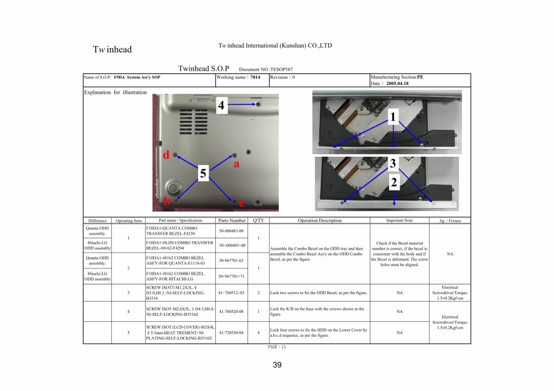
Quanta ODDassembly.
F10DA1-QUANTA COMBOTRANSFER BEZEL-F4230 50-000483-00
Hitachi-LGODD assembly
F10DA1-HLDS COMBO TRANSFERBEZEL-#8162-F4294 50+000485+00
Quanta ODDassembly.
F10DA1-#8162 COMBO BEZELASS'Y-FOR QUANTA-E1118-03 50-967701-62
Hitachi-LGODD assembly
F10DA1-#8162 COMBO BEZELASS'Y-FOR HITACHI-LG 50+967701+71
3SCREW ISOTT-M1.2X3L,∮D3.0,H0.3 -NI-SELF-LOCKING-B3516
41+760512+03 2 Lock two screws to fix the ODD Bezel, as per the figure. NAElectrical
Screwdriver/Torque:1.5±0.2Kgf-cm
4 SCREW ISOT-M2.6X5L,∮D4.5,H0.8-NI-SELF-LOCKING-B3516Z
41-760520-08 1 Lock the K/B on the base with the screws shown in thefigure. NA
5SCREW ISOT (LCD COVER)-M3X4L∮5.3mm-HEAT TREMENT+NIPLATING-SELF-LOCKING-B3516Z
41-720530-04 4 Lock four screws to fix the HDD on the Lower Cover bya.b.c.d sequence, as per the figure. NA
2
1
1
Assemble the Combo Bezel on the ODD tray and thenassemble the Combo Bezel Ass'y on the ODD ComboBezel, as per the figure.
Twinhead S.O.P Document NO :TESOP587Name of S.O.P﹕F9DA System Ass'y SOP Working name:7014 Manufacturing Section:PE
PAGE:15
1
Date: 2005.04.18
Explanation for illustration
Check if the Bezel materialnumber is correct, if the bezel isconsistent with the body and if
the Bezel is deformed. The screwholes must be aligned.
NA
ElectricalScrewdriver/Torque:
1.5±0.2Kgf-cm
Tw inhead International (Kunshan) CO.,LTDTw inhead
5a
b c
d
4
23
1
39

Revision:0
PAGE:16
Twinhead S.O.P Document NO :TESOP587Name of S.O.P﹕F9DA System Ass'y SOP Working name:7015 Manufacturing Section:PE
Date: 2005.04.18
Explanation for illustration
Tw inhead International (Kunshan) CO.,LTDTw inhead
Gap between LCDModule and Hinge Cap:Less than 1.2mm
Gap between LCD Module andBase: Less than 1.7mm
(1) Gap between LCDand panel: Less than0.8mm.
Gap of four corner of LCDModule: Less than 0.8mm
Gap between LowerCover and Bezel: Lessthan 1.0mm
Upper cover and Bezel:Gap: Less than 1.0mmSTEP: Less than 0.3mm
Upper cover and battery:DEEP: Less than 0.3mmGAP: Less than 0.8mm
Gap between ODD Bezel andlower cover: Less than 1.4mm.
Gap between batteryand lower cover: Lessthan 0.8mm
BATTERY and LOWERCOVER Gap=<0.8mm
Finish line of four sides:Gap: Less than 0.8mmStep: Less than 0.5mm
Finish line of four sides:Gap: Less than 0.8mmStep: Less than 0.5mm
Gap between upper and lowercovers: Less than 0.8mm.
Gap between LCDModule and Hinge Cap:Less than 1.2mm
Gap around thepush key: Lessthan 0.3mm.
2
4
5
63
1
7
40

Revision:0
Difference Operating Item Part name / Specification Parts Number Q'TY Operation Description Important Note Jig / Fixture
W/INTEL ID F10DA1-FCC RATING LABEL-EN-FOR INTEL ID-F4358 63+040280+20
KO F10DA1-FCC RATING LABEL-KO-F4358 63+040280+10
W/MSI ID F10DA1-FCC RATING LABEL-EN-FOR MSI ID-F4358 63+040280+30
PAGE:17
Twinhead S.O.P Document NO:TESOP587Name of S.O.P﹕F10DA System Ass'y SOP Working name:7016 Manufacturing Section: PE
Date: 2005.04.18
Explanation for illustration
1 1 Attach the FCC Label onto the base according to theposition shown in the figure. NABe square without floating.
Tw inhead International (Kunshan)Tw inhead
1
41

Tw inhead International (Kunshan) CO.,LTD
REVISION: 0
PREPARED BY CONCURREDBY APPROVED BY
1. NEW RELEASE PE: Li, Shin Prepared by:
QC:
Tw inhead
F10DA 10.6" LEC Pre-Assembly SOP
DOCUMENT CODE:TESOP586
RELEASE DATE:
PAGE: 11 (total 13 pages)
DESCRIPTION
42

Page No. /Revision No. List:
Page No. Rev. No. Page No. Rev. No. Page No. Rev. No.Page No. Rev. No.
1. Table of Contents P.01 1 0
2. Machine Assembly Material List/Operation Instrutions/Illustrations P.02~P.11 2 0
(Work number: 11 persons, including test) 2-1 0
3. References 3 0
1. Plastics Injection Inspection Rules (see D/C No.: KE3-0113) 4 0
2. Electrical Screwdriver Operation Standard (see D/C No.:KE3-0010) 5 0
3. Appearance Inspection Specification KE3-0058. 6 0
4. Tools used: Electrical screwdriver, tape stand. 7 0
8 0
9 0
10 0
11 0
Actual material shall be selected according to BOM.
REV: 0
Document NO.:TESOP586
This SOP is applicable for F10DA 10.6" LCD Samsung, Sharp LCD Assembly.
Table of Contents/Manpower Distribution Chart for F10DA 10.6" LCD Assembly SOP
PAGE:01
Tw inhead International (Kunshan) CO.,LTDTw inhead
43

Revision:0 Manufacturing Section:PEDate:2005.04.18
Difference Operating Item Part name / Specification Parts Number Q'TY Operation Description Important Note Jig / FixtureF10DA1-#8561-M LCD COVER ASS'Y-FORSHARP-E1118-01 40-967701-03
F10DA1-#8167-M LCD COVER ASS'Y-FORSHARP-E1118-01 (pearly white) 40-967701-91
F10DA1-#8466-M LCD COVER ASS'Y-FORSHARP-E1118-01 40-967701-72
F10DA1-#8561-M LCD COVER ASS'Y-FORSAMSUNG-E1118-02 40-967701-13
F10DA1-#8167-M LCD COVER ASS'Y-FORSAMSUNG-E1118-02 (pearly white) 40-967701-A1
F10DA1-#8568-M LCD COVER ASS'Y-FORSAMSUNG-E1118-02 (dark blue) 40-967701-B1
F10DA1-#8369-M LCD COVER ASS'Y-FORSAMSUNG-E1118-02 40-967701-C0
F10DA1-#8470-M LCD COVER ASS'Y-FORSAMSUNG-E1118-02 40-967701-D0
F10DA1-#8471-M LCD COVER ASS'Y-FORSAMSUNG-E1118-02 40-967701-E0
F10DA1-#8972-M LCD COVER ASS'Y-FORSAMSUNG-E1118-02 40-967701-F0
F10DA1-#8162-M LCD COVER ASS'Y-FORSAMSUNG-E1118-02 40-967701-G0
F10DA1-#8472-M LCD COVER ASS'Y-FORSAMSUNG-E1118-02 40-967701-H0
F10DA1-#8466-M LCD COVER ASS'Y-FORSAMSUNG-E1118-02 40-967701-82
2 F10DA1-ANTENNA-L-D3058 22-600151-00 1
3 F10DA1-ANTENNA-R-D3057 22-600150-00 1
PAGE: 02
NA
Strip the adhesive tape from the backside of leftand right antennas and assemble them on theLCD cover, with conducting pad attached toLCD cover securely.
The conducting padmust be attached flat
and the antenna screwholes must be aligned.
Twinhead S.O.P Document NO.:TESOP586Name of SOP:F10DA 10.6" LCD MODULE ASS'Y SOP Working name:6512-1
NA NA
Explanation for illustration
1 Check the appearance and no bruise or staindamage is allowed.1
SHARP LCDAssembly
SAMSUNGLCD
Assembly
Tw inhead International (Kunshan) CO.,LTDTw inhead
32
44

Revision:0 Manufacturing Section:PEDate:2005.04.18
Difference Operating Item Part name / Specification Parts Number Q'TY Operation Description Important Note Jig / Fixture
1 NA NA 1
Check the appearance of "AVERATEC" logo onthe LCD cover. Press the internal Logo with a jigalong the slot lightly, sticking it in the slot. If theadhesion of Logo is poor, pick the defective oneand replace new Logo.
The Logo should bekept from lifting. Jig
PAGE: 02-1
Explanation for illustration
Twinhead S.O.P Document NO.:TESOP586Name of SOP:F10DA 10.6" LCD MODULE ASS'Y SOP Working name:6512-1-1
Tw inhead International (Kunshan) CO.,LTDTw inhead
1
45

Revision:0 Manufacturing Section:PEDate:2005.04.18
Difference Operating Item Part name / Specification Parts Number Q'TY Operation Description Important Note Jig/Fixture
LCD-10.6" TFT WXGA-SAMSUNG-LTN106W2-L01 72-11026S-00
LCD-10.6" TFT WXGA-SAMSUNG-LTN106W2-L01-TRIGEM CSG 72-11026S-00TRI
SHARP LCD LCD-10.6" TFT WXGA-SHARP-LQ106K1LA01A 72-11023J-00
SAMSUNG LCD F10DA1-HARNESS FOR SAMSUNG LCD-SH773 29-001773-01 Watch the lead-out
position, as per the figure.Harness positioning
jig.
SHARP LCD F10DA1-HARNESS FOR SHARP LCD-SH772 29-001772-00 NA NA
3 ALL MODEL-INSULATING TAPE-20mmX66m.T=0.5mm (broad white tape, 3cm) 27-309091-00 1 Fix the LCD harness end connection port with a
white tape, as per the figure.
4 ALL MODEL-INSULATING TAPE-10mmX66m,T=0.5mm(narrow white tape, 5cm) 27-309090-00 1 Fix the lower LCD harness with a tape, as per the
figure.
5 Maker's barcode/keyparts Label NA 2Verify the LCD maker barcode and attach the produced makerbarcode on the LCD protection film,and then stick the Keypartslabel on the backside of LCD, as per the figure.
NA Barcode machine
PAGE: 03
2 1 Assemble the LCD harness on the LCD port, as perthe figure.
Attach the tape securelyand keep wires from lifting. Tape stand
Twinhead S.O.P Document NO.:TESOP586Name of SOP:F10DA 10.6" LCD MODULE ASS'Y SOP Working name:6512-2
Explanation for illustration
NA11Do not press the PCB onthe backside of LCD with
hand.
Check the appearance of LCD panel and scratches,bruise and stain damage are not allowed.
SAMSUNG LCD
Tw inhead International (Kunshan) CO.,LTDTw inhead
5 2
3
4
Keep the lead-outaway from left side for48mm
1
The SAMSUNG LCD harness shall notexceed the right side of the upper slotopening
5 Sharp LCDattaching
SAMSUNG LCDattaching position
46

Revision:0 Manufacturing Section:PEDate:2005.04.18
Difference Operating Item Part name / Specification Parts Number Q'TY Operation Description Important Note Jig / Fixture
1 F10DA1-LCD BRACKET-L FORSAMSUANG-D3055 40-031653-00 1 NA NA
2 ISOTT SCREW-M2X4L,∮D3.5mm,H-0.5-NI-SELF-LOCKING-HEAT TREATMENT-B3516
41-761520-04 2 NAElectrical
Screwdriver/Torque: 1.0±0.2Kgf-cm
3 F10DA1-LCD BRACKET-R FORSAMSUANG-D3054 40-031654-00 1 NA NA
4 ISOTT SCREW-M2X4L,∮D3.5mm,H-0.5-NI-SELF-LOCKING-HEAT TREATMENT-B3516
41-761520-04 2 NAElectrical
Screwdriver/Torque: 1.0±0.2Kgf-cm
5 NA NA 1
Allow the upper part of LCD body to contact theupper part of LCD cover. Tip it slightly and pushupward to the end, and then place it under theLCD for assemble in the LCD cover.
The screw holes on the ironframe must align with that onthe LCD cover, and do not let
the upper part of LCD press theantenna wires.
NA
PAGE: 04
Explanation for illustration
Assemble the right side iron frame of LCD andthen fix two screws tightly.
Assemble the left side iron frame of LCD andthen fix two screws tightly.
SAMSUNG LCDAssembly
Twinhead S.O.P Document NO.:TESOP586Name of SOP:F10DA 10.6" LCD MODULE ASS'Y SOP Working name:6512-2
Tw inhead International (Kunshan) CO.,LTDTw inhead
1
Right side ofLCD
Left side of LCD
2
4
3
47

Revision:0 Manufacturing Section:PEDate:2005.04.18
Difference Operating Item Part name / Specification Parts Number Q'TY Operation Description Important Note Jig / Fixture
INVERTER-5V-SUMIDA-IV10123/T F10D-098 76-030117-00 1
Date Code Label (month label) 63-000041-XX 1
2 ISOTT SCREW-M2X4L,∮D3.5mm,H-0.5-NI-SELF-LOCKING-HEAT TREATMENT-B3516
41-761520-04 4 Lock screws to fix the LCD in the LCD cover,as per the figure. NA
Electricalscrewdriver/Torque:
1.5±0.1Kgf-cm
Twinhead S.O.P Document NO.:TESOP586Name of SOP:F10DA 10.6" LCD MODULE ASS'Y SOP Working name:6512-4
PAGE: 05
Description of Illustrations
Strip the backside tape of high-pressure smalpanel and assemble it on the positioning pole atthe LCD cover base, and then stick the monthlabel on the high-pressure small plate as per thefigure.
NAThe inverter must be assembledparallel without slanting.1
Tw inhead International (Kunshan) CO.,LTDTw inhead
Trim the LCD harness downward intothe gap on the left side of LCD cover,and do not let the wire to lift up.
2
SHARP LCD
SAMSUNG LCD1
48

Revision:0 Manufacturing Section:PEDate:2005.04.18
Difference Operating Item Part name / Specification Parts Number Q'TY Operation Description Important Note Jig /Fixture
1 F10DA1-HINGE-R-D3050 40-015140-01 1 NA
2 F10DA1-COVER FOR LCD HINGE-R-#8160-D3048 50-035294-01 1 NA
3 F10DA1-MYLAR FOR HINGE-R-F4249 50-023634-00 1 Attach Mylar of right spindle on the right spindle, as perthe figure. Be square without floating . NA
The small hole on the right sideof spindle shall align with thepositioning pole in the Hinge
Cover hole.
PAGE: 06
Explanation for illustration
Twinhead S.O.P Document NO:TESOP586Name of SOP:F10DA 10.6" LCD MODULE ASS'Y SOP Working name:6512-5
Check the appearance of right spindle and the cover.Penetrate the LCD harness and antenna together throughthe spindle and right cover holes, and then assemble asper the figure.
4 SCREW ISOT-M2.6X3L-SELF-LOCKING-B3516Z 41-720526-03
ElectricalScrewdriver/Torque:
2.5±0.2Kgf-cm2
Lock two screws to fix the LCD spindle, as per thefigure. When locking the left-side screw, press theconductor pad with hand.
Upon locking the left-side screw ofright spindle, the LCD harness shall
be locked on the spindle togetherwith the conductor pad. The right-side angle of spindle should be 90
degrees.
Tw inhead International (Kunshan) CO.,LTDTw inhead
1
2
Check the LCD with a jig to set the LCD harnessbelow the surface of LCD, as per the lower partmarked with red line in the figure.
SAMSUNG LCD wiret i i
SHARP LCD wire
4Hold the upper part of conductor pad onthe LCD harness with a hand and lock thescrew. The conductor pad must be locatedat the position shown in the figure withoutslanting.
Before locking the screw in place, check ifthis part is 90 degrees. Lock the screwwhen it becomes 90 degrees.
3
49

Revision:0 Manufacturing Section:PE
Date:2005.04.18
Difference Operating Item Part name / Specification Parts Number Q'TY Operation Description Important Note Jig / Fixture
1 NA NA 1Arrange the wires into the positioning polein place, as per the figure, and then pull theexcessive wires from right spindle slowly.
Keep the wire from lifting. Bamboo chopsticks
2 F10DA1-BLUETOOTH ANTENNA-F4246 22-600152-00 1As per the figure, check the appearance ofBluetooth antenna and then assemble theBluetooth Antenna in the LCD cover.
NA NA
3ISOTT SCREW-M2X4L,∮D3.5mm,H-0.5-NI-SELF-LOCKING-HEAT TREATMENT-B3516
41-761520-04 1 Lock one screw to fix the Bluetooth antenna,as per the figure. NA
ElectricalScrewdriver/Torque:
1.0±0.1Kgf-cm
Twinhead S.O.P Document NO:TESOP586
Explanation for illustration
PAGE: 07
Name of SOP:F10DA 10.6" LCD MODULE ASS'Y SOP Working name:6512-6
When theBluetooth is
used.
Tw inhead International (Kunshan) CO.,LTDTw inhead
Trim the antenna wires in thegap while keeping them fromlifting up.
The antenna must be trimmed on theleft side of positioning pole in place.
Both antennas must be arrangedin the gap on the right side ofLCD while keeping the wiresfrom lifting up.
31 2
50

Revision:0 Manufacturing Section:PEDate:2005.04.18
Difference Operating Item Part name / Specification Parts Number Q'TY Operation Description Important Note Jig /Fixture
1 F10DA1-HINGE-L-D3049 40-015141-01 1 NA
2 F10DA1-COVER FOR LCD HINGE-L-#8160-D3047 50-035295-00 1 NA
3 F10DA1-MYLAR FOR HINGE-L-F4250 50-023633-00 1 Attach the Mylar of left spindle on the spindle as theposition shown in the figure.
The mylar should be attachedsquarely without slanting and
floating.NA
5 NA NA 1Connect the LCD harness to the left and right connectionports of the Inverter and then arrange the LCD harness andBluetooth wires as per the figure.
The wire must be arrangedfrom the gap above the
Inverter.NA
6 Acetic tape (approx. 3cm long) NA 2 Attach two pieces of acetic tape to fix the left and rightside of LCD harness, as per the figure.
Keep the wires fromlifting. NA
Align the small hole on theleft side of spindle with the
positioning pole in theHinge Cover.
41-720526-03 Electrical Screwdriver/Torque:2.5±0.2Kgf-cm2 Lock two screws to fix the left spindle of LCD, as per the
figure.
Check if the angle of leftside of the spindle is 90
degrees.
PAGE: 08
Explanation for illustration
Twinhead S.O.P Document NO:TESOP586Name of SOP:F10DA 10.6" LCD MODULE ASS'Y SOP Working name:6512-7
Check the appearance of left spindle and left spindlecover and then assemble the cover and the spindle as perthe figure.
4 SCREW ISOT-M2.6X3L-SELF-LOCKING-B3516Z
Tw inhead International (Kunshan) CO.,LTDTw inhead
4
2
13
6
5SAMSUNG LCD wire trimming
Make sure this part be 90 degreesbefore locknig the screw in place.When it becomes vertical, lock thescrew tightly.
51

Revision:0 Manufacturing Section:PEDate:2005.04.18
Difference Operating Item Part name / Specification Parts Number Q'TY Operation Description Important Note Jig / Fixture
1 F10DA1-LCD PANEL-#8160-B1380 50-034120-00 1 NA
2 F10DA1-MAGNET-F4247 27-600050-00 1 NA
3 F10DA1-LCD SPONGE-FOR MAGENTIC-F4 51-036300-00 1 NA
4 NA NA NA Assemble LCD Panel and LCD Cover. NA NA
5 F10DA1-LCD RUBBER-WHITE-F4238 52-002421-00 1 Attach white LCD Rubber on the upperpart of LCD Panel, as per the figure.
The LCD Rubber besquare without floating. NA
PAGE: 09
Explanation for illustration
Make sure the LCD Panel is free ofscratch or bruise . Strip the double-faceglue paper from the magnetic stone andfix it on the left side hole of LCD paneland then attach one foam on thesurface to cover up the magnetic stone,as per the figure.
Do not let the magneticstone fall.
Twinhead S.O.P Document NO:TESOP586Name of SOP:F10DA 10.6" LCD MODULE ASS'Y SOP Working name:6512-8
Tw inhead International (Kunshan) CO.,LTDTw inhead
1
5
2
3
52

Revision:0 Manufacturing Section:PEDate:2005.04.18
Difference Operating Item Part name / Specification Parts Number Q'TY Operation Description Important Note Jig/Fixture
ElectricalScrewdriver/Torque
: 2.0±0.2Kgf-cm
NA
Explanation for illustration
2 F10DA1-RUBBER FOR LCD PANEL-WHITE-F4239
41-761520-04 4
Twinhead S.O.P Document NO:TESOP586Name of SOP:F10DA 10.6" LCD MODULE ASS'Y SOP Working name:6512-9
PAGE: 10
1
52-002420-00 2 Attach two rubber pads on the position at theupper part of LCD Panel, as per the figure.
Be square withoutfloating.
ISOTT SCREW-M2X4L,∮D3.5mm,H-0.5-NI-SELF-LOCKING-HEAT TREATMENT-B3516
NALock four screws to fix the LCD Panel, as perthe figure.
Tw inhead International (Kunshan) CO.,LTDTw inhead
12
53

Revision:0 Manufacturing Sectoin:PEDate:2005.04.18
Difference Operating Item Part name / Specification Parts Number Q'TY Operation Description Important Note Jig /Fixture
NA
NANA
Place the assembled LCD in theprotection bag and then load in the carton.
PAGE: 11
NANA
2 NA1NA
Make sure the appearance is free ofscratch,bruise and poor assembly. Placethe protection cotton pad on the LCDPanel and then cut one piece of LCDprotection film to wrap around the LCD
NA
Explanation for illustration
1
Twinhead S.O.P Document NO:TESOP586Name of SOP:F10DA 10.6" LCD MODULE ASS'Y SOP Working name:6512-10
1
Tw inhead International (Kunshan) CO.,LTDTw inhead
1
54

55

56

57

58

59