Embed Size (px)
Citation preview

F1 : Introduction to HDLs
What does HDL stand for?
HDL is short for Hardware Description Language
(VHDL - VHSIC Hardware Description Language)
(Very High Speed Integrated Circuit)
Why use an HDL?
1
1 1 1 1
1 1 1 1
1 1 1 1
ab
de
c
1
1
1
1
ab
de
f = ab+cd+ce
Why use an HDL?
a
b
d
e
c
f
a
b
cf
d
e
Why use an HDL?
Question:
How do we know that we have not made a mistake
when we manually draw a schematic and connect
components to implement a function?
Why use an HDL?
Answer:
By describing the design in a high-level (=easy to
understand) language, we can simulate our design
before we manufacture it. This allows us to catch
design errors, i.e., that the design does not work as we
thought it would.
• Simulation guarantees that the design behaves as it should.

Why use an HDL?
Corollary:
By letting a tool convert the high-level description into
hardware (assuming that we can mathematically prove
that the tool works correctly - which is impossible
today), we can then guarantee that what we have
simulated is actually what we get.
• Synthesis guarantees that the translation to hardware is done
correctly
What is a Hardware Description Language?
HDL is short for Hardware Description Language
(VHDL - VHSIC Hardware Description Language)
(Very High Speed Integrated Circuit)
The CabinetThe Cabinet
Network of processors withNetwork of processors with
system software.system software.
What do we mean with hardware?
Printed Circuit Boards (PCB)Printed Circuit Boards (PCB)
Single/Parallel processor systemsSingle/Parallel processor systems
with dedicated software, for instance with dedicated software, for instance
for controlling a robot’s arm.for controlling a robot’s arm.
What do we mean with hardware?
MultiMulti--Chip Modules (MCM)Chip Modules (MCM)
Single processors withSingle processors with
software, RAMsoftware, RAM--
and ROMand ROM--memories formemories for
storage.storage.
What do we mean with hardware?
Circuits Circuits -- ASIC/FPGAsASIC/FPGAs
What do we mean with hardware?
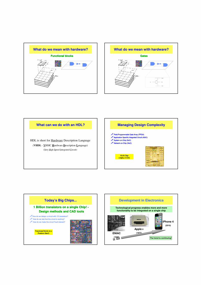
Functional blocksFunctional blocks
What do we mean with hardware?
GatesGates
VDDVDD
VSSVSS
OutOutInIn
What do we mean with hardware?
What can we do with an HDL?
HDL is short for Hardware Description Language
(VHDL - VHSIC Hardware Description Language)
(Very High Speed Integrated Circuit)
Managing Design Complexity
�� Field Programmable Gate Array (FPGA)Field Programmable Gate Array (FPGA)
��Application Specific Integrated Circuit (ASIC) Application Specific Integrated Circuit (ASIC)
�� SystemSystem--onon--Chip (SoC)Chip (SoC)
�� NetworkNetwork--onon--Chip (NoC)Chip (NoC)
VLSI ChipVLSI Chip
(Alpha 21164)(Alpha 21164)
Today’s Big Chips...
��How do we design a circuit with 1G transistors?How do we design a circuit with 1G transistors?
�� How do we test that the circuit is working?How do we test that the circuit is working?
�� How do we make the circuit FaultHow do we make the circuit Fault--tolerant?tolerant?
1 Billion transistors on a single Chip! 1 Billion transistors on a single Chip! --
Design methods and CAD toolsDesign methods and CAD tools
Functional blocks in a Functional blocks in a
Pentium (Intel)Pentium (Intel)
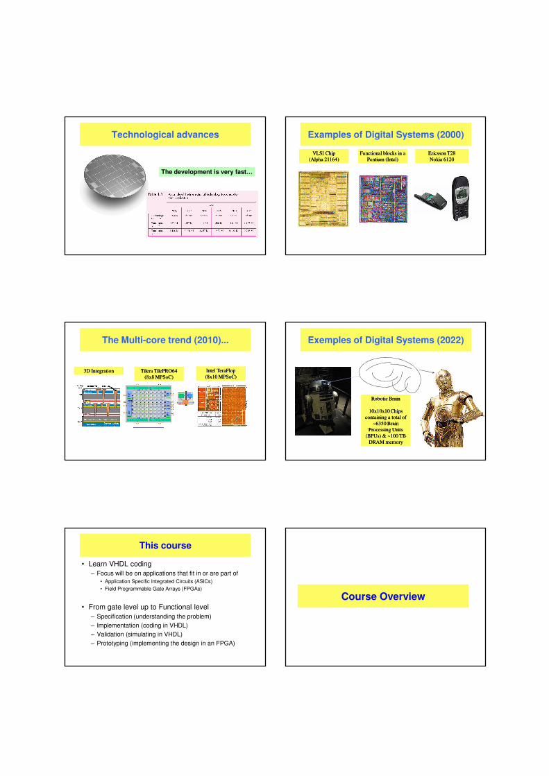
Development in Electronics
Apple II
(1977)
The trend is continuing!
ENIAC
(1946)
iPhone 4
(2010)
Technological progress enables more and more
functionality to be integrated on a single chip
Technological advances
The development is very fast…
Examples of Digital Systems (2000)
Ericsson T28Ericsson T28
Nokia 6120Nokia 6120
VLSI ChipVLSI Chip
(Alpha 21164)(Alpha 21164)
Functional blocks in a Functional blocks in a
Pentium (Intel)Pentium (Intel)
The Multi-core trend (2010)...
3D Integration3D Integration TileraTilera TilePRO64 TilePRO64
(8x8 (8x8 MPSoCMPSoC))
Intel Intel TeraFlopTeraFlop
(8x10 (8x10 MPSoCMPSoC))
Exemples of Digital Systems (2022)
Robotic BrainRobotic Brain
10x10x10 Chips 10x10x10 Chips
containing a total ofcontaining a total of
~6350 Brain ~6350 Brain
Processing Units Processing Units
(BPUs) & ~100 TB (BPUs) & ~100 TB
DRAM memoryDRAM memory
This course
• Learn VHDL coding– Focus will be on applications that fit in or are part of
• Application Specific Integrated Circuits (ASICs)
• Field Programmable Gate Arrays (FPGAs)
• From gate level up to Functional level– Specification (understanding the problem)
– Implementation (coding in VHDL)
– Validation (simulating in VHDL)
– Prototyping (implementing the design in an FPGA)
Course Overview
Some Administrative Details
• Course ResponsibleJohnny Öberg [email protected]
• Exercise assistants
Johnny Öberg [email protected]
• Laboration AssistantsFrancesco Robino [email protected]
Mohammad Badawi
...
Visiting Address
• We are working in the
Dept. of Electronic Systems (ES),
School of Information and Communication Technology (ICT)
• Visiting Address:KTH-Forum, Isafjordsgatan 39, Kista (Elevator C, 8th Floor)
• Postal Address:KTH/ICT/ES, Forum 105, SE-164 40 Kista
Preliminary Lecture order…
1 – VHDL Basics
2 – Modeling Styles
3 – Functions, Procedures & Data Types
4 – Resolved Functions & Databuses
5 – Latches, Flip-flops and FSMs
6 – RTL Coding & The Synthesizable subset
7 – FSMDs – FSMs with a Datapath
8 – The CPU - Modeling Complex Systems
9 – Asynchronous State Machines
10 – Introduction to Verilog
11 – Introduction to System C
IL1331 IL2217
Course Overview
• Examination– The labs are different in the two courses. IL1331 labs are more basic and
have less theory questions. No bonus points are given on labs.
– We use continuous examination in IL2217. A lab passed gives points to the exam. All labs passed gives 10 points (one grade step).
– A written exam consisting of two parts, part A (VHDL and the hardware structures they represent) and part B (Theory).
– IL1331 students only do part A. To pass the exam, the student need to have at least half of the points (25p) to get grade E.
– IL2217 students do both part A and B. To pass the exam, the student need have at least (20p) on EACH part of the exam and have a total of at least 50 points (including lab points) on the exam to get grade E.
Course information on the web!
• Course PM available at
http://www.ict.kth.se/courses/IL1331/ and
http://www.ict.kth.se/courses/IL2217
• Updates to labs posted as soon as possible(in case of errors)
• Lecture notes (copy of the slides) posted right before or right after the lecture.
IL1331 Lab Overview
• We are building a tiny processor from scratch:1) The Adder
2) The ALU
3) Memories and Datapaths
4) The Controller
5) Single-Chip Computer
6) Putting it all together
7) Putting it all together
IL2217 Lab Overview
• There are 4 obligatory labs (Exam points in parenthesis):
0) Introduction to VHDL and Modelsim (voluntary - 0p)
1) Combinational circuits (2p)
2) Resolution Functions & Data buses (2p)
3) Counters & Finite State Machines (2p)
4) The Micro controller (mini processor) (4p)
Course Overview
• Labs (4h scheduled every week – 7 in total)
– Labs 0-3 take ~4-8 hours each to complete, depending on the student’s programming skills.
– Labs 4 takes ~8-16 hours to complete.
• Students must prepare labs at home to manage!
NOTE!
– Lab hours are for examination and to ask questions from assistants if you get stuck. Not for coding. The students should think about the problem(s) first and prepare code and questions before coming to the lab. Otherwise, the labs will take a very long time to complete.
– You don’t need to finish a lab within the scheduled time. If you do not finish one lab in time, continue where you were the next time you come. You may of course also do the labs on your own at other hours (unless occupied by others) or do the labs at home.
– During the scheduled lab hours, there will be assistants around to answer/ask questions and to check your progress.
F1 : Introduction to VHDL
VHDL Basics
There are two types of VHDL code:
• VHDL targeted for synthesis (the synthesizable subset)
• VHDL targeted for simulation (used for high-level modeling and
in test benches, i.e., for testing purposes)
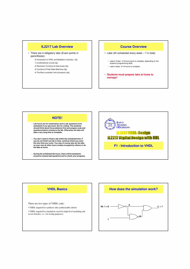
How does the simulation work?
1
IN: 1->0A
B
C = ?
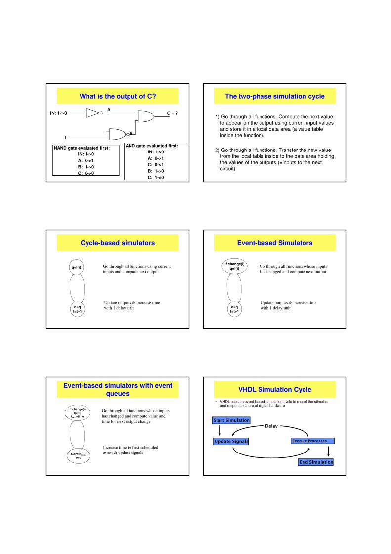
What is the output of C?
1
IN: 1->0A
B
C = ?
C: 0->0
NAND gate evaluated first:
IN: 1->0
A: 0->1
B: 1->0
C: 0->0C: 1->0
AND gate evaluated first:
IN: 1->0
A: 0->1
C: 0->1
B: 1->0
C: 1->0
The two-phase simulation cycle
1) Go through all functions. Compute the next value to appear on the output using current input values and store it in a local data area (a value table inside the function).
2) Go through all functions. Transfer the new value from the local table inside to the data area holding the values of the outputs (=inputs to the next circuit)
Cycle-based simulators
Go through all functions using current
inputs and compute next output
Update outputs & increase time
with 1 delay unit
q=f(i)
o=qt=t+1
Event-based Simulators
Go through all functions whose inputs
has changed and compute next output
Update outputs & increase time
with 1 delay unit
if change(i)q=f(i)
o=qt=t+1
Event-based simulators with event queues
Go through all functions whose inputs
has changed and compute value and
time for next output change
Increase time to first scheduled
event & update signals
if change(i)
q=f(i)
tnext=time
t=first(tnext)
o=q
VHDL Simulation Cycle
• VHDL uses an event-based simulation cycle to model the stimulus and response nature of digital hardware
Start Simulation
Update SignalsUpdate Signals Execute Processes
End SimulationEnd Simulation
Delay
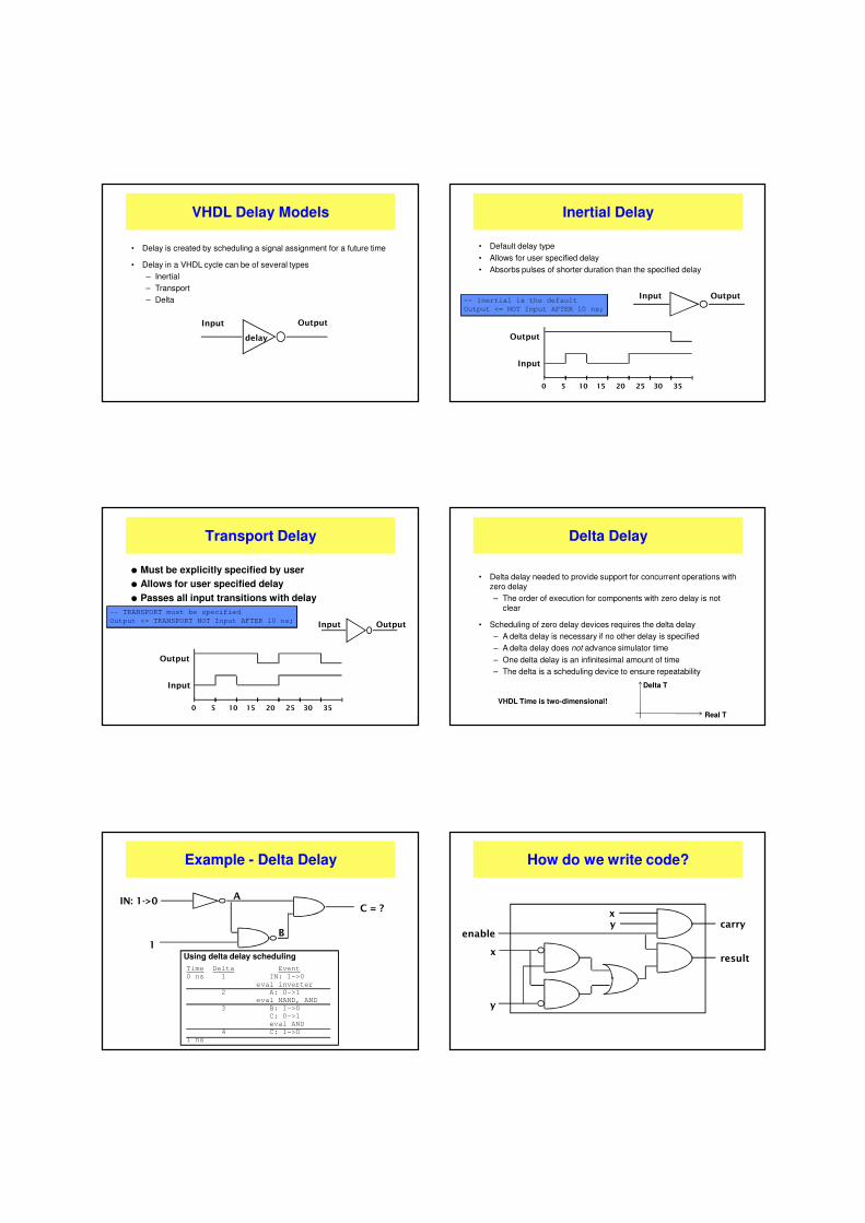
VHDL Delay Models
• Delay is created by scheduling a signal assignment for a future time
• Delay in a VHDL cycle can be of several types
– Inertial
– Transport
– Delta
Input Output
delay
Inertial Delay
• Default delay type
• Allows for user specified delay
• Absorbs pulses of shorter duration than the specified delay
-- Inertial is the default
Output <= NOT Input AFTER 10 ns;
Input Output
Input
Output
0 5 10 15 20 25 30 35
Transport Delay
l Must be explicitly specified by user
l Allows for user specified delay
l Passes all input transitions with delay
-- TRANSPORT must be specified
Output <= TRANSPORT NOT Input AFTER 10 ns;Input Output
Input
Output
0 5 10 15 20 25 30 35
Delta Delay
• Delta delay needed to provide support for concurrent operations with zero delay
– The order of execution for components with zero delay is not clear
• Scheduling of zero delay devices requires the delta delay
– A delta delay is necessary if no other delay is specified
– A delta delay does not advance simulator time
– One delta delay is an infinitesimal amount of time
– The delta is a scheduling device to ensure repeatability
Real T
Delta T
VHDL Time is two-dimensional!
Example - Delta Delay
IN: 1->0
1
A
B
C = ?
Using delta delay scheduling
Time Delta Event
0 ns 1 IN: 1->0
eval inverter
2 A: 0->1
eval NAND, AND
3 B: 1->0
C: 0->1
eval AND
4 C: 1->0
1 ns
How do we write code?
xy
enable
x
y
carry
result

The black box model
• Primary level of abstraction in VHDL is the entity
• In a behavioral description, the entity is defined by its responses to signals or input
• A behavioral model is similar to a "black box"
– Interior is hidden from view
– Behavior of entity is defined by the relationship of the input to the output
Input OutputBehavioral Entity
Entity Declaration
• An entity declaration describes the interface of the component
• PORT clause indicates input and output ports
• An entity can be thought of as a symbol for a component
x
y
enable
carry
result
HalfAdder
ENTITY half_adder IS
PORT( x, y, enable: IN bit;
carry, result: OUT bit);
END half_adder;
Port Declaration
• PORT declaration establishes the interface of the object to the outside world
• Three parts of the PORT declaration
– Name• Any identifier that is not a reserved word
– Mode• In, Out, Inout, Buffer, Linkage
– Data type• Any declared or predefined datatype
• Sample PORT declaration syntax:
ENTITY test IS
PORT( name : mode data_type);
END test;
Predefined Data types
- bit (‘0’ or ‘1’)
- bit_vector (array of bits)
- integer
- real
- time (physical data type)
Architecture Declaration
• Architecture declarations describe the operation of the component
• Many architectures may exist for one entity, but only one may be active at a time
• An architecture is similar to a schematic of the component
yenable
x
y
carry
result
ARCHITECTURE behave OF half_adder IS
BEGIN
PROCESS (enable, x, y)
BEGIN
IF (enable = '1') THEN
result <= x XOR y;
carry <= x AND y;
ELSE
carry, result <= “00”;
END IF;
END PROCESS;
END behave;
x
Signals - Declaration & Assignments
ARCHITECTURE <architecture_name> OF <entity_name> IS
-- The signal declaration is used inside architectures to
-- declare internal signals:
-- signal a,b,sum:bit;
signal a,b,sum:bit_vector(31 downto 0);
BEGIN
-- The signal assignment is used to describe behaviour:
sum<=a xor b;
END <architecture_name>;
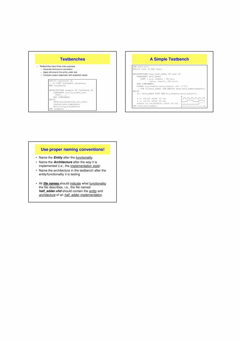
Testbenches
• Testbenches have three main purposes
– Generate stimulus for simulation
– Apply stimulus to the entity under test
– Compare output responses with expected values
ENTITY testbench IS
-- no PORT statement necessary
END testbench;
ARCHITECTURE example OF testbench IS
COMPONENT entity_under_test
PORT(...)
END COMPONENT;
BEGIN
Generate_waveforms_for_test;
Instantiate_component;
Monitoring_statements;
END example;
A Simple Testbench
USE work.all;
ENTITY test IS END Test;
ARCHITECTURE test_half_adder OF test IS
COMPONENT half_adder
PORT ( x,y, enable : IN bit;
carry, result: OUT bit);
END COMPONENT;
SIGNAL x,y,enable,carry,result: bit :=‘0’;
-- FOR U1:half_adder USE ENTITY work.half_adder(behave);
BEGIN
U1: half_adder PORT MAP(x,y,enable,carry,result);
x <= not(x) after 10 ns;
y <= not(y) after 20 ns;
enable <= not(enable) after 40 ns;
END test_half_adder;
Use proper naming conventions!
• Name the Entity after the functionality
• Name the Architecture after the way it is implemented (i.e., the implementation style)
• Name the architecture in the testbench after the entity/functionality it is testing
• All file names should indicate what functionalitythe file describes, i.e., the file named half_adder.vhd should contain the entity and architecture of an half_adder implementation.


![FPGA-Based Soft-Core Processors for Image Processing ... · FPGA-Based Soft-Core Processors for Image Processing ... (HDLs) such as VHDL and Verilog [6]. The HDL approach allows a](https://img.dokumen.tips/doc/110x75/5f8b4ebe675f536b434c4af2/fpga-based-soft-core-processors-for-image-processing-fpga-based-soft-core-processors.jpg)


![Active Hdl[1].Quick.start.guide.vhdl](https://img.dokumen.tips/doc/110x75/545cb517b1af9fdd0c8b46f9/active-hdl1quickstartguidevhdl.jpg)


![Subject Code HDL 2003[1]](https://img.dokumen.tips/doc/110x75/577d2f721a28ab4e1eb1bd74/subject-code-hdl-20031.jpg)
