Embed Size (px)
Citation preview
Exposed SeriesWall System
InstallationGuide

MORINCORP.COM * BRISTOL, CT * FONTANA, CA * DELAND, FL * T: 800-640-9501
Exposed Series
Introduction 1Design Data 2Technical Data 5Storage of Materials 8Panel Handling: Forklift 9Panel Handling: Crane 10Panel Handling: Individual Panel 11Panel Handling: Flatstock 12Clips & Panel Assembly 14Testing 15Fastening Guidelines 16Panel Installation 17Basic Installation Tools 21Field Metal Cutting Tool 22Pre-Installation Check List 23Installing Exposed Series 24Vertical Details Index 25Horizontal Details Index 45Standard Trim 64Maintenance Instruction 67Appendix A: Panel Profiles & Fastening Patterns 68
MANUAL DOES NOT APPLY TO ZINC OR COPPER APPLICATIONS
Contents
Disclaimer:
The details are provided as a guideline for proper panel and associated component design, and are based on industry
accepted practices. Panel spans, clip spacing and fastener recommendations are project specific and should be
determined by the engineer of record.
Insulation, purlins/joists, decking, miscellaneous structural supports etc. are shown for clarity only, and are not supplied by
Morin (N.B.M.). For project specific engineering and design assistance, as well as information on radius panel options,
please contact Morin Technical Services.
IMPORTANT: Please read all information related to your project before receiving materials at the job site and before
starting the installation.

1
MORINCORP.COM * BRISTOL, CT * FONTANA, CA * DELAND, FL * T: 800-640-9501MORINCORP.COM * BRISTOL, CT * FONTANA, CA * DELAND, FL * T: 800-640-9501
Exposed Series
EXPOSED FASTENER WALL SERIES:
Exposed Fastener Series manual is an introduction to Morin’s recommendations. While some of these
recommendations may or may not be agreed to by all, it must be remembered that these are the methods that we
recommend and/or require to activate the warranties to our material upon completion of a project.
The Exposed Fastener Series systems (i.e. panels, closures, trim) can be designed into walls on both new and retrofit
construction. Please contact your local representative for further information. Flashing are not standard, but are
fabricated for specific job requirements. Our suggested details for these conditions are included in the following
sections of this manual.
WARRANTIES:
Morin can furnish the various extended performance warranties as required by a project’s specification. The items
covered by this warranty are standard and include such items as material & finish performance. Contact your local
representative for a sample copy of these warranties. The above warranties cover only the materials furnished by
Morin and will not become valid until all remittance is complete for warranty.
Morin does not offer weathertightness warranty for the Exposed Fastener Series panel.
INSTALLATION:
Morin recommends that our Exposed Fastener Series panel should be installed under the direct supervision of an
experienced sheet metal craftsman trained in the proper application of the system.
MATERIAL SPECIFICATIONS:
The Exposed Fastener Series panel is supplied in various cover widths of 24" up to 40" (nominal) and the standard
material thickness is 24 through 18 gauge for steel, as well as 0.032”, 0.040”, and 0.050” for aluminum. All panels are
supplied with either a non-coated mill finish or with a prefinished coating using standard 1.0 mil Fluorocarbons and
High Build Fluorocarbons, depending on the project’s performance requirements. Standard panel fabrication lengths
are available from 5' (1.52m) up to 30’ (9.14m). Longer lengths of panel are available however not recommended due
to handling restrictions.
COOL METAL WALL AND LEED®:
Morin’s Exposed Fastener Series meets the requirements of these programs. Contact your local representative for
additional information.
Introduction

2
MORINCORP.COM * BRISTOL, CT * FONTANA, CA * DELAND, FL * T: 800-640-9501MORINCORP.COM * BRISTOL, CT * FONTANA, CA * DELAND, FL * T: 800-640-9501
Exposed Series
Design Data
THERMAL MOVEMENT:
As mentioned earlier in this manual, movement due to thermal expansion and contraction must be taken into
consideration during design. This affects the trim conditions, clip spacing, and type.
Coefficient of expansion:
Steel 0.00065"
Aluminum 0.00128"
Concrete 0.00055"
HOW TO CALCULATE PANEL LENGTH CHANGE:
Sample Calculation:
Given: Original Panel Length = 55’
Temperature Change = 90°F
Panel Length Calculation (PLC):
PLC = 0.00065 x Temperature change x Original panel length PLC = 0.00065 x 90 x 55 = 0.032’ or 3/8”
100 100
Temperature variation in the metal panels is not constant across the surface. This differential effect causes the parts of
the wall to expand/contract at different times. The variation in movement affects both the panels and structure, even if the
components are of the same material. A correct design should use a minimum daylight ambient temperature of 160°F for
bare aluminum to in excess of 200°F for dark coated panels. Another factor to be considered is radiant heat. At night this
can cause low temperatures well under ambient temperature. The difference here has been measured as 30°F in very
thin dry air climates and as high 20°F in very high humidity at sea level.
Gross panel thermal expansion is handled at each vertical rib in the wall system. If structural expansion joints are needed,
then special panel connections will be required. Please contact the Morin Technical Department for their suggested
details. Some of the items that must be considered for a correct detail are the proper selection of clips, clip placement and
the design and fabrication of trim.
In some cases when you have ventilators or other large wall openings, then a fixed point at some other location may be
needed. If this becomes a fact then a fixed point must be located so that there is no relative movement between adjacent
panels. Please contact our Technical Department for their suggested details. Other areas of concern are those of
irregular shapes and conditions which may require the use of panel splice plates. Our suggested details for these items
are found in a section of this manual.
In addition to the above, a designer must also give some thought concerning such accessory items and/or flashing. All of
these trim items must be designed and fastened to adequately account for their expected thermal movement. Standard
trim length in fabrication is 10'. Everything mentioned above applies to both steel and aluminum. With aluminum this is
very critical, in as much as it’s coefficient of expansion is twice that of steel. In either case, steel or aluminum, trim lengths
should not exceed 20’ in order to try to eliminate the elongation of fastener holes, oilcans or kinks. Flashing lap joints
must be allowed to move. Screws or rivets should not be used to hold flashing lengths together. Several types of joinery
that allow for thermal movement are shown in our detail section found in this manual.
In areas where it is not feasible to furnish full length factory fabricated panels because of either shipping limitations or
adding to the length of existing wall panels, it will be required to use a panel splice plate. For weather resistance, these
are designed to be sealed joints with structural fixpoint connections that prevent relative movement between adjacent
panels. The reason for this is that any movement may over stress the sealant and cause a leak or cause fastener holes to
elongate with the same leak results.

3
MORINCORP.COM * BRISTOL, CT * FONTANA, CA * DELAND, FL * T: 800-640-9501MORINCORP.COM * BRISTOL, CT * FONTANA, CA * DELAND, FL * T: 800-640-9501
Exposed Series
Design Data
PANEL GAUGE SELECTION:
Some of the items that must be considered when selecting the minimum gauge of a wall panel are material types, panel
width and panel rib height. Economy in gauge selection may be had if the lightest gauge available meets the performance
requirements of the project. If this is found to be the case, then structural wall panel systems can be fabricated in heavier
gauges or girt spacing can be designed to allow for the maximum span of the wall panel system selected. Sometimes
economies of gauge girts can outweigh the cost savings of using the wall panel systems maximum spans. These
components should be taken into account in order to receive the best overall cost for the project.
PANEL SUBSTRATE DETERIORATION:
In the metal panel industry, deterioration is generally known to be “corrosion”. Corrosion is nothing more than metal
oxidation, (i.e. red rust/steel or white rust/aluminum). In order to fight this problem, it is recommended that only stainless
steel or metal coated/plated fasteners or clips be used in the wall panel system. The reason for this is that there is the
possibility of water condensation at the base of the fastener, which could accelerate fastener deterioration. All fasteners
must be compatible with the panel substrate in order to allow the building envelope to have a long performance in the
project’s atmospheric environment.
PANEL DEFLECTION:
Building codes in most cases do not set limits on the deflection of wall cladding; therefore this item is overlooked in the
design of wall panel systems. Usually these codes limit the deflection to structural members only if other materials
supported are sensitive to great movement and/or cracking. Deflection should be calculated if there is concern for
drainage or the possibility of a clearance problem with secondary structural members. The Southern Building Code and
BOCA limit deflection to L/180 while the Aluminum Association sets the limit at L/60. However, the designer should always
check the local codes for the limits that they should set and these limits should be included in the project specifications.
Uniform loading changes the wall panel products section properties as the panel distorts, (i.e. panels become more rigid
under positive loads and more flexible under negative loads).
To determine the actual allowable negative load ability of a wall panel system a full-scale wind uplift test should be run.
From these tests, a negative load table with appropriate safety factors can be developed. Positive load capacity can be
calculated using the products section properties and in accordance with AISI Specifications. The flat of the wall panel, at
its intersection with its vertical rib, when put under a positive or negative load, will deflect. In checking clearances, both
positive and negative clearances must be determined.
FLOOR DEFLECTION:
The structural design needs to be checked for floor deflection or structural shrinkage when wall panels are installed on a
multi-floor building. If the framing is not outboard of the floors, the wall panel system needs to be designed to allow for
floor deflection and movement. The most common way to address the issue is with a stack or slip joint at each floor.

4
MORINCORP.COM * BRISTOL, CT * FONTANA, CA * DELAND, FL * T: 800-640-9501MORINCORP.COM * BRISTOL, CT * FONTANA, CA * DELAND, FL * T: 800-640-9501
Exposed Series
Design Data
FABRICATION TOLERANCE:
The Metal Construction Association (MCA) has developed tolerances for acceptable manufacturing practices. These
tolerances are now considered to be the metal panel industry standard and are published in the MCA Manual. The following
is a brief summary of these tolerances:
Panel Length + / – 3/8”
Panel End Squareness
Viewed from Panel Front 0.5% of width or
measured across sheet no more than 1/8” at one end
Viewed from Panel Side 2.0% of panel
measured across sheet depth or no
more than 1/16”
Camber 3/16” per 10’ length
(lateral bow of panel viewed
from panel front)
Squareness should be measured using the panel "diagonal difference" method. Generally both ends will
be parallel so 1/8" out of square at an end can correspond to 1/4 inch diagonal difference. Squareness thus determined is a
function of panel length and width.
If the tabulated level of camber renders a particular product unserviceable for reasons other than aesthetics,
it shall not be acceptable. Other "as fabricated" profile dimensional tolerances (e.g. cover width and sub-element lengths,
radii and angular tolerances) can be somewhat meaningless. These dimensions are difficult to consistently measure and
the profiles are difficult to sustain during transit and installation. Sometimes profile must be field adjusted for in place
aesthetics. The final "in place" condition is the essential factor.
PANEL END SQUARENESS
T
o
le
r
a
n
c
e
Viewed from panel side
measured across sheet
Tolerance
1
0
'
-
0
"
CAMBER
.
3
8
"
PANEL LENGTH

5
MORINCORP.COM * BRISTOL, CT * FONTANA, CA * DELAND, FL * T: 800-640-9501MORINCORP.COM * BRISTOL, CT * FONTANA, CA * DELAND, FL * T: 800-640-9501
Exposed Series
Design Data
Tolerance
Plumb line
W + Tolerance
.
1
8
"
PANEL/ TRIM PLUMBNESS FANNING OF PANELS
Flat panel with Butt seamFluted Panels
To
le
ra
nce
End Offset
PANEL ALIGNMENT
Datum
line
Datum
line
To
le
ra
nce
To
le
ra
nce
Sp
acin
g
± 1
"
.
Typical side lap
Line of girt
BASE FLASHING ALIGNMENTEXPOSED FASTENER
INSTALLATION TOLERANCES:
MCA tolerances for installation of materials are as follows:
Panel Plumbness (in wall plane) 1/4” in 20’
Trim Plumbness (Unless controlled by 1/4” in 20'
structure and must align with adjacent steel or
masonry for aesthetic or service reasons)
Fanning of Panels 1/8” per panel
(Restores line or create module)
Fluted panels (Fanning uniformly
distributed across the panel)
Flat panels with Butt Seam 1/8” per seam
Panel Alignment at End or End Laps 3/16” at panel end
(End Offset or Saw-tooth. Accumulation 1/4” lap below 40’
of fabrication and installation tolerances
shall not exceed
1
4
" at base.
Base flashing alignment: (measured at brake 1/2” in 12'
point and not at free end; non accumulative)
Exposed Fastener: Alignment- variance across panels. 1/2” in a bay
Spacing- Along panel trim (+/-) 1"

6
MORINCORP.COM * BRISTOL, CT * FONTANA, CA * DELAND, FL * T: 800-640-9501MORINCORP.COM * BRISTOL, CT * FONTANA, CA * DELAND, FL * T: 800-640-9501
Exposed Series
PRODUCT SUMMARY:
The Exposed Fastener Series features seventeen unique profiles
(produced in several facilities). For wall applications, all Exposed
Fastener Series panels are reversible with many asymmetrical panels
offering a completely different profile per side chosen.
PRODUCTION LENGTHS:
Lengths 5' (1.52m) to 30' (9.14m) Standard
Longer lengths available (not recommended due to handling restrictions)
APPLICATIONS:
Weather-resistant or rainscreen rear-ventillated applications.
Installed in Vertical or Horizontal orientations.
PRODUCT OFFERINGS:
Panel Type - Wall Panel
Panel Depths -
1
2
" to 4" (See Appendix A for all depth options)
Cover Widths - 24" to 40" (See Appendix A for all width options)
MATERIAL OPTIONS:
Painted Steel: Galvalume/Zincalume 18GA (1.19mm), 20GA (.91mm),
22GA (.76mm), 24GA (.60mm)
Stainless Steel: 20GA, 22GA and 24 GA
Aluminum: 0.050GA (1.27mm), 0.040GA (1mm) and 0.032GA (.81mm)
COLOR AND FINISH OPTIONS FOR ALUM. AND STEEL:
Standard (Fluropon
®
PVDF-Kynar500
®
)
Premium Colors MICA (Fluropon Classic
®
II PVDF)
Premium Colors METALLIC (Fluropon Classic
®
PVDF)
Morin Custom Color Matching Services
Other Finishes Available
Surface Options- Smooth surface standard
Sealant- Optional factory sealant available
Substrate- Open framing or other various
backup wall assemblies
(i.e. exterior sheathing, air/water barrier,
exterior insulation)
Technical Data
STANDARD PROFILE OPTIONS FOR ALL PROFILES, SEE APPENDIX A ON PAGE 68
PROFILE A
PROFILE B
BR-28 (Example)
BR-28 (Example)

7
MORINCORP.COM * BRISTOL, CT * FONTANA, CA * DELAND, FL * T: 800-640-9501MORINCORP.COM * BRISTOL, CT * FONTANA, CA * DELAND, FL * T: 800-640-9501
Exposed Series
STRUCTURAL – POSITIVE AND NEGATIVE LOADS:
The Exposed Fastener Series panel systems capacities are based on the requirements of ASTM E1592 and the A.I.S.I “Cold
Formed Steel Design Manual”. Actual negative loads are determined by an independently certified load test of production run
panels. ASCE 7 is the basis of use with most major code bodies that specifies that higher negative pressures be used at the
perimeters and thus the fasteners must be spaced closer together to allow for the increased negative pressures when compared
to the general field of the wall. This means that if an open girt design is used, then the girt spacing at the perimeter must be
shortened to allow for the smaller spans required by the Exposed Fastener Series system. Determination of the required wind
negative pressure (psf) for all wall loading areas must be provided in the specifications and/or drawings by the architect and/or
engineer of record. This information is needed in order to make the correct panel selection and fastener spacing during the
bidding process. Also carefully review the submittal to verify that the fasteners that secure the clip to the structure are adequate
to resist the negative loads mentioned above.
THERMAL LOADS – PRESSURE PARALLEL TO THE WALL:
Structural supports are exposed not only to wind loads, but also to expansion and contraction thermal loads due to temperature
induced friction forces at the anchor points. Generally speaking these forces can be ignored, but in some cases they can build
up quite rapidly and become very noticeable. They should definitely be checked when panel length exceeds 35’. A basic
assumption is that a friction induced forced is additive, allowing a 20 pound per fastener friction allowance is then conservative
based on the “stick/slip” movement of the panel in relation to the fastener. It is highly unlikely all fastener resistance is at the
same place at the same time.
FIRE RATINGS:
Morin’s wall systems are fabricated from either steel or aluminum. These materials are generally considered by most code
bodies and fire jurisdictions to qualify as fire retardant wall coverings. Because of this they may be used with other materials to
satisfy a requirement for an hourly rated system to meet a specific fire protection need. Contact our technical department for
various rates up to 4 hours. UL rates the wall systems in either steel or aluminum as a Class A Wall Covering for use over girt or
non-combustible decks.
AIR AND WATER INFILTRATION:
Air and Water Infiltration testing has been conducted on the Exposed Fastener Series panel system in accordance with ASTM
E283 and ASTM E 331.
Technical Data

8
MORINCORP.COM * BRISTOL, CT * FONTANA, CA * DELAND, FL * T: 800-640-9501MORINCORP.COM * BRISTOL, CT * FONTANA, CA * DELAND, FL * T: 800-640-9501
Exposed Series
· Morin recommends that all materials be stored in a dry condition. An area should be provided, maintained and
assigned by the general contractor. This area should be clean, level, accessible and sufficiently compacted to
support and permit movement of delivery trucks and construction equipment.
· The materials should be stored sloped to allow drainage of condensation. All materials should be allowed to
breathe in order to deter build-up of condensation. The materials should be protected from weather by suitable
covering. Aluminum materials should be stored in a dry covered location.
· Materials should be inspected upon delivery for presence of moisture or damage. If moisture is present, bundles
should be opened immediately and dried.
· Temperature sensitive items such as butyl tapes and sealants should be stored under controlled conditions to
maintain suitable application characteristics.
· Materials with protective plastic peel coat must be shielded from UV exposure and prolonged heat or cold.
Excessive storage duration or exposure to severe temperature swings may cause peel coat to permanently
adhere to finish of panel.
· Special care is required for non-color aluminum materials. The presence of moisture can cause storage stain.
Care must be taken to assure moisture does not condense on the panel surface.
· Remove panels from bundles with caution. Tilt or lean the bundle on one side creating a slope that will prevent
the panels from falling in an outward or sliding motion. Care in removing panels from a bundle is the
responsibility of the contractor!
TO AVOID DAMAGE TO THE PANEL FINISH, PROTECTIVE PEEL COAT MUST BE REMOVED WITHIN 30 DAYS OF RECEIPT OF MATERIAL.
Storage of Material
Please feel free to contact our shipping department if you have any questions or need further
information regarding product handling. TOLL FREE: (800) 640-9501
Morin Northeast East- Corporate HQ (860) 584-0900Corporate HQ and Manufacturing Location 685 Middle Street, Bristol CT 06010 (800) 640-9501
Morin South South- Manufacturing & Testing (860) 584-0900Manufacturing and Testing Location 1975 Eidson Drive, Deland FL 32724 (800) 640-9501
Morin West West- Manufacturing (909) 428-3747Manufacturing Location 10707 Commerce Way, Fontana CA 92337 (800) 700-6140
Contact Us

9
MORINCORP.COM * BRISTOL, CT * FONTANA, CA * DELAND, FL * T: 800-640-9501MORINCORP.COM * BRISTOL, CT * FONTANA, CA * DELAND, FL * T: 800-640-9501
Exposed Series
The recommended loading/unloading method for bundles less than or equal to 20' is to use a single forklift with widely
spaced forks placed under the center of the bundles as shown below in figure 1.
Wood surrounds or metal angles placed beneath the bundle will provide protection to the underside of material. Wood
surrounds will be spaced according to the center of bundle, especially at lift points where forks must meet wood
surrounds.
Panel bundles greater than 20' in length may be moved by using two forklifts spaced equally along the length of the
bundle as seen in figure 2. However, this method is *strongly discouraged due to the difficulty of co-coordinating
forklift movement. Use crane if available.
FIG.1 PREFERRED METHOD (1 FORKLIFT)
≤
2
0
'
-
0
"
(
≤
6
.
1
m
)
Panel Handling
Forklift:
FIG.2 *STRONGLY DISCOURAGED! (2 FORKLIFTS)
>
2
0
'
-
0
"
(
>
6
.
1
m
)

10
MORINCORP.COM * BRISTOL, CT * FONTANA, CA * DELAND, FL * T: 800-640-9501MORINCORP.COM * BRISTOL, CT * FONTANA, CA * DELAND, FL * T: 800-640-9501
Exposed SeriesPanel Handling
Crane:
The recommended crane lifting method is to use nylon straps positioned at a minimum of two points at equal
distances along the length of the bundle.
A steel spreader bar should be used for lifting all bundles. Suitable wood surrounds should be used and located at the
top, bottom and sides of the bundles to protect the panels as shown below in figure 3.
Steel spreader bar
2
0
'
-
0
'
'
(
6
.
1
m
)
Nylon straps
NOTE:
To prevent panels from damage while lifting,
carefully pick up bundles one at a time.
Wood surrounds
CRANE METHOD
Req'd Strap Spacing for Lifting Bundles:
LIFT POINTS BUNDLE LENGTHS
2 points up to 20'
3 points up to 30'
FIG.3
11
MORINCORP.COM * BRISTOL, CT * FONTANA, CA * DELAND, FL * T: 800-640-9501MORINCORP.COM * BRISTOL, CT * FONTANA, CA * DELAND, FL * T: 800-640-9501
Exposed SeriesPanel Handling
Individual Panel:
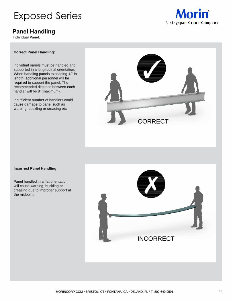
Correct Panel Handling:
Individual panels must be handled and
supported in a longitudinal orientation.
When handling panels exceeding 12' in
length, additional personnel will be
required to support the panel. The
recommended distance between each
handler will be 8' (maximum).
Insufficient number of handlers could
cause damage to panel such as
warping, buckling or creasing etc.
Incorrect Panel Handling:
Panel handled in a flat orientation
will cause warping, buckling or
creasing due to improper support at
the midpoint.
CORRECT
INCORRECT
12
MORINCORP.COM * BRISTOL, CT * FONTANA, CA * DELAND, FL * T: 800-640-9501MORINCORP.COM * BRISTOL, CT * FONTANA, CA * DELAND, FL * T: 800-640-9501
Exposed SeriesPanel Handling
Flatstock:
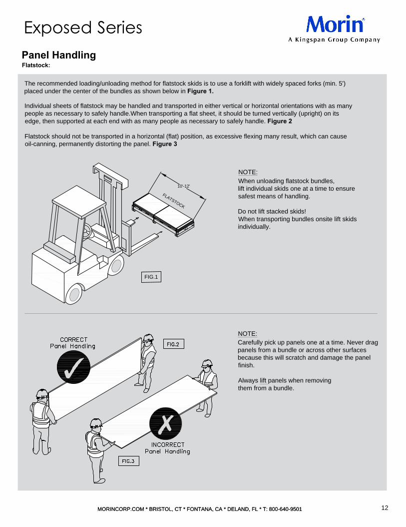
The recommended loading/unloading method for flatstock skids is to use a forklift with widely spaced forks (min. 5')
placed under the center of the bundles as shown below in Figure 1.
10'-12'
F
L
A
T
S
T
O
C
K
FIG.1
NOTE:
When unloading flatstock bundles,
lift individual skids one at a time to ensure
safest means of handling.
Do not lift stacked skids!
When transporting bundles onsite lift skids
individually.
NOTE:
Carefully pick up panels one at a time. Never drag
panels from a bundle or across other surfaces
because this will scratch and damage the panel
finish.
Always lift panels when removing
them from a bundle.
Individual sheets of flatstock may be handled and transported in either vertical or horizontal orientations with as many
people as necessary to safely handle.When transporting a flat sheet, it should be turned vertically (upright) on its
edge, then supported at each end with as many people as necessary to safely handle. Figure 2
Flatstock should not be transported in a horizontal (flat) position, as excessive flexing many result, which can cause
oil-canning, permanently distorting the panel. Figure 3

13
MORINCORP.COM * BRISTOL, CT * FONTANA, CA * DELAND, FL * T: 800-640-9501MORINCORP.COM * BRISTOL, CT * FONTANA, CA * DELAND, FL * T: 800-640-9501
Exposed Series
PROFILE B
BR-28 (Example)
Fastening Patterns
Refer to Appendix A for ALL Profile Fastening Patterns
PROFILE A
BR-28 (Example)
FASTENING REQUIREMENTS:
Per structural testing specifications, Morin requires strict adherence to the fastening patterns prescribed in this
Exposed Fastener Series Installation Guide.
Failure to comply to the fastening pattern required for any of the panels listed in Appendix A of this guide will result in
voidance of warranty and possible structural, architectural and weather-tightness issues upon installation.
If you have any questions regarding fastening patterns, fastener types, or other installation concerns, be sure to consult
with Morin Technical Department before the start of assembly to avoid unnecessary issues during installation.
*For specified fastener type, see details starting on page 26 of this installation guide.

14
MORINCORP.COM * BRISTOL, CT * FONTANA, CA * DELAND, FL * T: 800-640-9501MORINCORP.COM * BRISTOL, CT * FONTANA, CA * DELAND, FL * T: 800-640-9501
Exposed Series
Horizontal Assemblies must be installed from bottom to top (base to roof-line). Panels in a horizontal orientation must be
lapped over on another so as to prevent moisture from penetrating the system. The panels should be lapped atop one another
in an upward direction so that the final cell of the above panel rests on the below panel and is secured with a fastener
(specified in details to follow).
Vertical Assemblies are typically installed from left to right, however depending on construction requirements, can be installed
in either direction. Application of a vertical assembly is based on the design specifications of the architect and will typically be
installed in the direction where the least foot traffic occurs so that the lapping of the system is less noticeable.
*NOTE: The numbers & represent the order of assembly.1 2 3
Panel Assembly
VERTICAL ASSEMBLY
HORIZONTAL ASSEMBLY
FASTENER
FINISH SIDE

15
MORINCORP.COM * BRISTOL, CT * FONTANA, CA * DELAND, FL * T: 800-640-9501MORINCORP.COM * BRISTOL, CT * FONTANA, CA * DELAND, FL * T: 800-640-9501
Exposed Series
- ASTM E1592- Uplift Test
- ASTM E283 - Air Infiltration Test
- ASTM E331 - Water Infiltration Test
-Florida Product Approval
The Exposed Fastener Series panel from MORIN has undergone or is undergoing a wide variety of tests
that will allow for its installation anywhere, including where the strictest wind uplift codes and wind driven
rain requirements are in place.
The Exposed Fastener Series panels are undergoing (and expected to meet the requirements of):
Testing

16
MORINCORP.COM * BRISTOL, CT * FONTANA, CA * DELAND, FL * T: 800-640-9501MORINCORP.COM * BRISTOL, CT * FONTANA, CA * DELAND, FL * T: 800-640-9501
Exposed Series
Fastening Guidelines
EXPOSED SERIES FASTENER LOCATION:
Fasteners are to be spaced at the maximum spacing as shown on the calculations submitted to the architect at the time the
contractors make their material submittal, but must not exceed the maximum spacing as shown in the manufacturers literature
for the required loads. When the wall system is used over a solid substrate, the spacing of the fasteners must be examined to
be sure that this spacing does not exceed the spacing of the panel/fastening system but also does not exceed the strength of
the fastener, which connects the fastener to the substrate.
FASTENER LOAD CALCULATIONS:
To calculate the wind uplift loads for any fastener or fastener group, you must take the following items into account:
· Design wind load uplift.
· Tributary area of fastener.
· Fastener manufacturer’s information as to the pullout/pullover of the fastener being considered.
· The local building code safety factor requirements.
· As mentioned earlier in this manual, you should also check the loads that snow and expansion/contraction places on the
fastener to be sure that those loads do not exceed the fastener manufacturer’s recommendations.
FLASHING, TRIM & MISCELLANEOUS FASTENERS:
While Exposed Fastener Series panels are the primary concern when using the Morin wall system, you should not overlook
the importance of flashing and their fasteners. After all, a leak at this location is just as bad as a leak through the wall panel.
The fastener must be of a self sealing type with a sealing washer under its head on the exposed surface. The minimum size
fastener to be used to connect flashing and trim to the wall panel should be either a #10 screw or 1/8" rivet at 16”(MAX.)
SEALANTS:
The wall system is designed & manufactured to give 20 years of service. Because of this, it is our recommendation that the
sealants specified or used have an equal life expectancy. In applying sealants to a metal surface, one of the most important
aspects for a good seal is to have a clean and dry surface and that the sealant being used is applied in accordance with the
manufacturers recommendations. There are two types of joints on which sealant is required. They are exposed and
non-exposed joints. An exposed sealant joint should use a sealant that will have a final cure that will stay flexible.
Do not use either asphalt or oil base type sealant. For non-exposed sealant joints, use only non-hardening type sealant,
recommended by a sealant manufacturer. There are several installers that prefer to use a silicone type sealant. This type of
material will work fine as long as it has the 20-yr service life expectancy. One word of caution when using this product is that
you must be sure that it is a non-acetic acid cure.

17
MORINCORP.COM * BRISTOL, CT * FONTANA, CA * DELAND, FL * T: 800-640-9501MORINCORP.COM * BRISTOL, CT * FONTANA, CA * DELAND, FL * T: 800-640-9501
Exposed Series
1. COORDINATING THE INSTALLATION OF PANELS WITH OTHER TRADES
Careful attention prior to and during panel installation must be paid to the other trades working on the same project as
your wall installation. Failure to do so may result in compromised schedules and rising costs. For example, if there is
any new masonry and/or cement work on the same project, it should be scheduled prior to the wall panel installation,
so that the masonry/cement is complete and cured before any wall panels are installed.
Trades involved in electrical and HVAC may perform work in conjunction with the wall panel installation remembering
to coordinate the work such that those trades may perform their tasks while the walls are partially or completely
installed. Also keep in mind that some of the work performed by these trades may be detrimental to the wall structure
and the materials used are corrosive to metal walls; such as copper, pressure treated wood, and HVAC cleaners.
2. INSPECT THE STRUCTURE
The area designated to receive the new wall panels must be inspected and condition that fail to meet the requirement
of the all system must be reported PRIOR to general contractor beginning the installation process.
a. Checking for Flatness - Failing to confirm that the structure and the wall system are flat in plane of the elevation
will have a major impact on the success of the wall panel installation. Straight, level, plumb and plane are not the
same. Straight is a line between two points without curves or bents. Level is a horizontal line with respect to
distance above or below a given point. Plumb is vertical upright straight line ninety degree off level. Plane is a
flat, level, horizontal or vertical surface.
1. Starting at the base line of the wall set a point 4 inches off the corner and 1 inch off the wall, pull a line or
shoot a laser line level to a point 4 inches off the opposite corner and 1 inch off the wall. Measure multiple
places off the line back to the wall. This will determine if the wall is straight at the base line.
2. Set up a plumb bob or laser off the base line point to the top of the panel run. Measure multiple places off
the line back to the wall. This will determine if the wall is straight from bottom to top.
3. Set up point off the plumb line at the top of the panel run and pull a line or shoot a laser line level to the
opposite corner. Measure multiple places off the line back to the wall. This will determine if the wall is
straight at the top of the wall.
4. Set up a plumb bob or laser at the opposite corner set point at the top of the panel run. The plumb line and
the level bottom point should lineup. Measure multiple places off the line back to the wall. This will determine
if the wall is plumb at the opposite wall.
5. After setting up the perimeter line you can check multiple places to determine if the wall is in plane.
See diagram:
Panel Installation
2
3 4
BASE LINE PLUMB LINE
TOP LINE PLUMB LINE OPPOSITE END
1

18
MORINCORP.COM * BRISTOL, CT * FONTANA, CA * DELAND, FL * T: 800-640-9501MORINCORP.COM * BRISTOL, CT * FONTANA, CA * DELAND, FL * T: 800-640-9501
Exposed Series
b. In-plane alignment (Wall to Wall) - While a walls substrate may have been installed square, straight, and flat, it
may still not have been installed correctly. The wall must be installed in-plane with the rest of the structure and other
planes, otherwise it will not appear correct and performance may be compromised. When wall surfaces are not
in-plane, it can sometimes be referred to as a “crooked” wall. In this scenario, even though each wall is straight, they
are not straight to each other. Remember that misalignment may occur the intersection of different walls and
transition sections. A misaligned or crooked wall will present performance issues, and appearance issues, creating
gaps, misalignment, and oil canning in the panels.
SUBSTRATE
SUBSTRATE
Panel Installation

19
MORINCORP.COM * BRISTOL, CT * FONTANA, CA * DELAND, FL * T: 800-640-9501MORINCORP.COM * BRISTOL, CT * FONTANA, CA * DELAND, FL * T: 800-640-9501
Exposed Series
3. FLATNESS
Straightness involves the edges of an object while flatness entails the wide, open surfaces of an object.
Installed walls panels must be both straight and flat. The issue of oil- canning on a metal wall is directly
related to panel surfaces which are not flat.
Examples of this are pre-cambered stud walls; subgirts out of alignment and support members having
been twisted.
Panel Installation
4. SUSTAINING PANEL MODULARITY AND ALIGNMENT
The relationship of the installed wall panel to other installed wall panels, wall structure members and the
structure that the wall rests upon is called panel modularity. Modularity affects the strength, performance and
aesthetics factors of the finished wall.
a. Starting Square To The Base - The technique of starting the first panel as “plumb and level” will
establish a baseline and reference for the remaining panels, and impact the appearance and performance of
the finished wall.
b. Monitor and Measure During Installation - The measurement and monitoring of the wall, its members
and conditions during the installation are the responsibility of the installer. Once a square edge has been
determined and established as the reference, all distances must be measured from and compared to that
square edge/reference in order to effectively monitor and maintain squareness, never forgetting that
small errors grow over distance.
c. Sawtoothing at Base, End Laps and Ridge - Sawtoothing of the panels will occur when the wall panels
are not installed square to the base or edge. To avoid or reduce this risk the installer should always make
sure that the first panel installed is squared and plumb to the corresponding wall edge and aligned to panels
at other tiers.
Issues with Thermal Movement - Common causes of problems related to thermal movement are either
double-pinning of the wall panels (ex. fastening at both end of panel) and conditions that cause the panel clips
to bind, thereby not adjusting to the thermal movement of the panel.
The installer should:
a. Refer back to the Design Data section within this Matrix Series Manual, specifically the section on Thermal
Movement: Coefficient of Expansion and How to Calculate Panel Length Change.
b. Confirm that the panel fastening method is aligned with those as shown in the erection drawing or the
manufacturer's instructions. Verify that all involved with this installation are also aware as to the panel
fastening method.
c. Be aware of installation of accessories or any panel modification and that these do not create a
double-pinning of the wall panels.
d. Inspect and approve the sealant requirements around any clips and ensure that the fasteners are not
damaged and allow the panel to move freely as designed.

20
MORINCORP.COM * BRISTOL, CT * FONTANA, CA * DELAND, FL * T: 800-640-9501MORINCORP.COM * BRISTOL, CT * FONTANA, CA * DELAND, FL * T: 800-640-9501
Exposed Series
Panel Installation
5. BEST PRACTICES FOR FIELD CUTTING THE PANELS AND TRIM
Tools:
Tools approved for cutting metal include electric or pneumatic nibblers, electric sheet metal shears, sheet
metal hand shears and aviation snips, circular saws fitted with specially formulated carbide blades designed
for cutting metal.
For field cutting sheet metal, follow these simple rules:
a. Avoid abrasive or other blades which will heat the metal and create heavy burrs. This is especially true when
working with coated steel, as it will exceed the melting temperature of the metallic coating, melt it away from
the cut edge, and cause a site for corrosion to occur.
b. When cutting panels, a lot of steel bits, (commonly referred to as swart) get scattered and thrown onto
adjacent surfaces. If not thoroughly and promptly cleaned up and removed, this swart will cause potential
corrosion or heavy staining.
c. Some trimming and cutting of panels and trim pieces is to be expected with every installation. You risk
jeopardizing the appearance and performance of a wall system by failing to cut the metal wall materials
correctly.

Exposed Series
21
MORINCORP.COM * BRISTOL, CT * FONTANA, CA * DELAND, FL * T: 800-640-9501MORINCORP.COM * BRISTOL, CT * FONTANA, CA * DELAND, FL * T: 800-640-9501
· Measuring Tape
· Pencil
· Offset. Straight and Left Cut. Red Grip Snaps (a)
· Offset. Straight and Right Cut. Green Grip Snaps (b)
· Utility Knife and Blades
· 6" Vise-Grip Locking C-Clamps
(c)
· Pop Rivet Tool (d)
· 6" Speed Square
(e)
· Tool Belt
· 1
1
2
" Wood Chisel
· Hammer. Straight Claw 16 oz. (f)
ADDITIONAL TOOLS TO SPEEDUP INSTALLATION:
· Duckbill. Vise-Grip. Locking Sheet Metal Tool
(g)
· 12" Speed Square
· Construction Master, Contractor's Calculator
· Roper Whitney No. 5 Jr. Punch Kit (h)
· Hand Seamer
(i)
· Bend Moore. Hemming Tool
Can be purchased at most:
Lowes, Home Depot, Granger, Dynamic Fastener,
Triangle Fastener, Ram Tool, and Fastenal
Basic Installation Tool List:
(b)(a)
(d)
(g)
(e)
(i)
(h)
(f)
(c)

22
MORINCORP.COM * BRISTOL, CT * FONTANA, CA * DELAND, FL * T: 800-640-9501MORINCORP.COM * BRISTOL, CT * FONTANA, CA * DELAND, FL * T: 800-640-9501
Exposed Series
· Metal Cutting Circular Saw (a)
· Tenryu Steel-Pro Saw Blade for Circular Saw
· Nibbler (b)
· Porta - Band. Bandsaw (c)
· Sawzall. Reciprocating Saw (d)
· Kett Shears (e)
· Swanson Shear (f)
*Available at most Lowes, Home Depot, Granger, Dynamic Fastener, Triangle Fastener, Ram Tool, and Fastenal*
Field Metal Cutting Tool List:
(e)(d)(f)
(a)
(b) (c)

23
MORINCORP.COM * BRISTOL, CT * FONTANA, CA * DELAND, FL * T: 800-640-9501MORINCORP.COM * BRISTOL, CT * FONTANA, CA * DELAND, FL * T: 800-640-9501
Exposed Series
· Review contract documents and approved shop drawings prior to installation to verify that they match the
structure.
· Examine the structure for alignment prior to installation. Verify that all surfaces are
flat, plumb, level, straight, square, and within panel tolerances of ¼” in the plane of the wall. Any variance from
tolerances can affect panel performance, aesthetics, and installation. Variances must be reported to the general
contractor, and corrected by the responsible party before panel installation begins.
· Set benchmarks for panels/trim per contract documents and approved shop drawings. This will ensure better
panel alignment, easier panel installation, panel performance, and aesthetics for the project.
· Verify that all blocking, supports, and penetrations are in place before installation begins.
· Verify clip placement and fastening points based on project specific shop drawings and calculations.
· Verify that staged panels match the shop drawings based on specific elevation.
· Verify that panels/trim are clean and free of damage. Do not install any damaged materials.
· Verify that the installer has the proper tools for panel and trim installation.
· Verify that all equipment, safety gear, and procedures meet or exceed the OSHA approved standards.
*NOTE: Ensure that all conditions on the Pre-Installation Checklist are met prior to the installation of panels. If any
one of these conditions are not met, MORIN recommends that installation of panels not begin until the issue is
rectified.*
Pre-Installation Checklist List:

24
MORINCORP.COM * BRISTOL, CT * FONTANA, CA * DELAND, FL * T: 800-640-9501MORINCORP.COM * BRISTOL, CT * FONTANA, CA * DELAND, FL * T: 800-640-9501
Exposed Series
· Check approved shop drawings to building.
· Check panel layout per approved shop drawing.
· Check panel module.
· Check panel squareness.
· Set benchmark around building to determine panel layout to approved shop drawings.
· Layout fasteners for panel framing attachment, calculation, side lap and end lap.
· Measure out framing attachment and allow for panel end lap and side lap.
· Stack eight to ten panels together and line up panel ends.
· Mark fastener layout on top panel and pre-drill panels with 1/8” drill bit for pilot holes for fasteners.
· Install base trim straight and level around perimeter of building.
· Level first panel, first course, and install from the bottom up and lap panels away from the main entrance.
· Install tape sealant as required per approved shop drawings.
· Check panel level and module at each course as installed.
· Install door and window heads trim.
Installing Exposed Fastener Series for Vertical and Horizontal Applications

25
MORINCORP.COM * BRISTOL, CT * FONTANA, CA * DELAND, FL * T: 800-640-9501MORINCORP.COM * BRISTOL, CT * FONTANA, CA * DELAND, FL * T: 800-640-9501
Typical Wall Condition Layout
Coping Detail
Gravelstop Detail
Base at Curb or Edge of Slab Detail
Base at Slab Detail
Lap Detail
Door/Window/Louver Head Detail
Door/Window/Louver Sill Detail
Door/Window/Louver Jamb Detail
Intersection of Head, Jamb, & Sill
Front Soffit Detail
Front Soffit Detail
Back Soffit Detail
Back Soffit Detail
Endwall Detail
Outside Corner Detail
Inside Corner Detail
Penetration Isometric
Penetration Detail
Expansion Detail
Transition Detail
Standard Trim
Maintenance Instructions
Appendix A:Panel Profiles & Fastening Patterns
28
29
32
33
44
Vertical Details Index
Exposed Series
40
36
37
38
39
40
41
42a
42b
43
44
64
67
68
25
26
27
28
29
30
31
32
33
34
35
27
30
31
26
42
37
35
TYPICAL WALL CONDITION LAYOUT
39
41

2" MIN
5°
M
IN
FLASHING MK-E-01
ROOFING MEMBRANE
(NBM)
LAP TEK FASTENER
W/ SEALANT
1
2
" SUBGIRT
WEATHER & AIR BARRIER
SEALANT & RIVET
FLASHING FASTENER
FLASHING MK-E-02
1
4
" HWH TEK 3 FASTENER
STAGGER THE TOP AND BOTTOM
OF SUBGIRT TO FRAMING MEMBERS
WOOD BLOCK (NBM)
EXTERIOR SHEATHING &
ROOF MEMBRANE (NBM)
PANEL SUPPORT (NBM)
METAL AND FOAM CLOSURE
(SET IN SEALANT)
1
4
" HWK TEK 3
FASTENER W/ WASHER
5
°
M
A
X
FLASHING MK-E-03
OPTIONAL ONE PIECE TRIM
26
MORINCORP.COM * BRISTOL, CT * FONTANA, CA * DELAND, FL * T: 800-640-9501MORINCORP.COM * BRISTOL, CT * FONTANA, CA * DELAND, FL * T: 800-640-9501
COPING DETAIL
Exposed Series
Vertical Installation

EXTERIOR SHEATHING (NBM)
1
4
" HWH TEK 3 FASTENER
STAGGER THE TOP AND BOTTOM
OF SUBGIRT TO FRAMING MEMBER
WEATHER & AIR BARRIER (NBM)
1
2
" DEEP SUBGIRT
FLASHING MK-E-GS
ROOFING (NBM)
ROOFING MEMBRANE (NBM)
PANEL SUPPORT
(NBM)
STRUCTURE
(NBM)
WOOD BLOCK (NBM)
LAP TEK FASTENER
W/ SEALANT
METAL AND FOAM CLOSURE
(SET IN SEALANT)
1
4
" HWK TEK 3
FASTENER W/ WASHER
GRAVELSTOP DETAIL
27
MORINCORP.COM * BRISTOL, CT * FONTANA, CA * DELAND, FL * T: 800-640-9501MORINCORP.COM * BRISTOL, CT * FONTANA, CA * DELAND, FL * T: 800-640-9501
Exposed Series
Vertical Installation

1
4
" HWH TEK 3 FASTENER
STAGGER THE TOP AND BOTTOM
OF SUBGIRT TO FRAMING MEMBERS
1
4
" HWH TEK 3 FASTENER
W/ WASHER
EXTEND WEATHER &
AIR BARRIER (NBM)
1"
EXTERIOR SHEATHING
(NBM)
PANEL SUPPORT (NBM)
1
4
"
WE
EP
G
AP
1"
1
2
"
TOP/CURB
SELF ADHERING
BUTYL FLASHING TAPE
1
2
" DEEP SUBGIRT
WEATHER & AIR
BARRIER (NBM)
TOP/FLASHING
STRUCTURE (NBM)
SEALANT (NBM)
SEALANT & BACKER ROD
FLASHING MK-E-04 (STAGGER JOINTS)
BASE AT CURB OR EDGE OF SLAB DETAIL
28
MORINCORP.COM * BRISTOL, CT * FONTANA, CA * DELAND, FL * T: 800-640-9501MORINCORP.COM * BRISTOL, CT * FONTANA, CA * DELAND, FL * T: 800-640-9501
Exposed Series
Vertical Installation

PANEL SUPPORT (NBM)
EXTERIOR SHEATHING (NBM)
1
4
" HWH TEK 3 FASTENER
STAGGER THE TOP AND BOTTOM
OF SUBGIRT TO FRAMING MEMBERS
1
4
" HWH TEK 3
FASTENER W/ WASHER
EXTEND WEATHER & AIR BARRIER (NBM)
STRUCTURE (NBM)
SEALANT (NBM)
FLASHING MK-E-05
1
2
" DEEP SUBGIRT
SELF ADHERING
BUTYL FLASHING TAPE
WEATHER & AIR
BARRIER (NBM)
1
2
"
1
4
"
WE
EP
G
AP
SUBFLASHING
MK-E-05A
BASE AT SLAB DETAIL
29
MORINCORP.COM * BRISTOL, CT * FONTANA, CA * DELAND, FL * T: 800-640-9501MORINCORP.COM * BRISTOL, CT * FONTANA, CA * DELAND, FL * T: 800-640-9501
Exposed Series
Vertical Installation

LA
P
PANEL SUPPORT (NBM)
WEATHER &
AIR BARRIER (NBM)
4"
TAPE SEALANT
1
4
" HWH TEK 3
FASTENER W/ WASHER
SUBGIRT
EXTERIOR SHEATHING (NBM)
1
4
" HWH TEK 3 FASTENER
STAGGER THE TOP AND BOTTOM
OF SUBGIRT TO FRAMING MEMBERS
LAP DETAIL
30
MORINCORP.COM * BRISTOL, CT * FONTANA, CA * DELAND, FL * T: 800-640-9501MORINCORP.COM * BRISTOL, CT * FONTANA, CA * DELAND, FL * T: 800-640-9501
Exposed Series
Vertical Installation
NOTE: ALL LAP CONDITIONS MUST OCCUR AT A SUPPORT POINT*NBM=(NOT BY MORIN)

1
4
"
WE
EP
G
AP
PANEL SUPPORT (NBM)
DOOR, WINDOW OR LOUVER (NBM)
PRIMARY AIR SEAL (NBM)
PER MANUFACTURER RECOMMENDATIONS
EXTEND WEATHER & AIR BARRIER (NBM)
LAP TEK FASTENER
WEATHER SEAL (NBM)
1
4
" HWH TEK 3 FASTENER
STAGGER THE TOP AND BOTTOM
OF SUBGIRT TO FRAMING MEMBERS
1
4
" HWH TEK 3 FASTENER
W/ WASHER
SELF ADHERING BUTYL
FLASHING TAPE
FLASHING MK-E-04
1
2
" DEEP SUBGIRT
EXTERIOR
SHEATHING (NBM)
WEATHER & AIR
BARRIER (NBM)
1
2
"
FLASHING MK-E-06
DOOR/WINDOW/LOUVER HEAD DETAIL
31
MORINCORP.COM * BRISTOL, CT * FONTANA, CA * DELAND, FL * T: 800-640-9501MORINCORP.COM * BRISTOL, CT * FONTANA, CA * DELAND, FL * T: 800-640-9501
Exposed Series
Vertical Installation
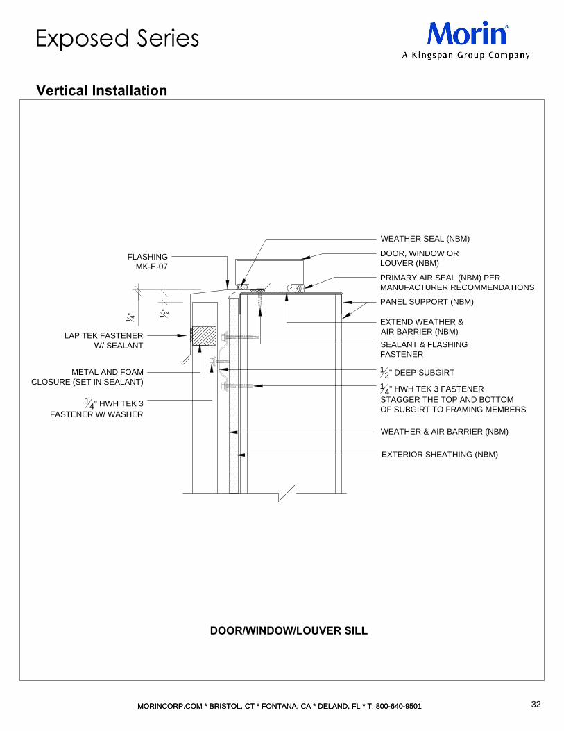
WEATHER & AIR BARRIER (NBM)
EXTERIOR SHEATHING (NBM)
METAL AND FOAM
CLOSURE (SET IN SEALANT)
FLASHING
MK-E-07
WEATHER SEAL (NBM)
1
4
" HWH TEK 3
FASTENER W/ WASHER
DOOR, WINDOW OR
LOUVER (NBM)
PANEL SUPPORT (NBM)
EXTEND WEATHER &
AIR BARRIER (NBM)
SEALANT & FLASHING
FASTENER
1
4
" HWH TEK 3 FASTENER
STAGGER THE TOP AND BOTTOM
OF SUBGIRT TO FRAMING MEMBERS
PRIMARY AIR SEAL (NBM) PER
MANUFACTURER RECOMMENDATIONS
1
2
"
1
4
"
1
2
" DEEP SUBGIRT
LAP TEK FASTENER
W/ SEALANT
DOOR/WINDOW/LOUVER SILL
32
MORINCORP.COM * BRISTOL, CT * FONTANA, CA * DELAND, FL * T: 800-640-9501MORINCORP.COM * BRISTOL, CT * FONTANA, CA * DELAND, FL * T: 800-640-9501
Exposed Series
Vertical Installation

1
2
" CLR
E/PANEL
WEATHER & AIR
BARRIER (NBM)
SELF ADHERING BUTYL
FLASHING TAPE
1
4
" HWH TEK 3 FASTENER
STAGGER THE TOP AND BOTTOM
OF SUBGIRT TO FRAMING MEMBERS
FLASHING FASTENER & SEALANT
EXTEND WEATHER &
AIR BARRIER (NBM)
DOOR, WINDOW OR LOUVER (NBM)
PRIMARY AIR SEAL (NBM)
PER MANUFACTURER
RECOMMENDATIONS
PANEL SUPPORT (NBM)
WEATHER SEAL (NBM)
FLASHING MK-E-08
FLASHING MK-E-09
EXTEND INTERIOR JAMB FLASHING
BELOW SILL OPENING MIN.1/2"
ONLY REQUIRED IF WINDOW TO
BE INSTALLED BEFORE PANELS
LAP TEK FASTENER W/ SEALANT
FLASHING MK-E-FILLER
1
4
" HWH TEK 3
FASTENER W/ WASHER
DOOR/WINDOW/LOUVER JAMB DETAIL
33
MORINCORP.COM * BRISTOL, CT * FONTANA, CA * DELAND, FL * T: 800-640-9501MORINCORP.COM * BRISTOL, CT * FONTANA, CA * DELAND, FL * T: 800-640-9501
Exposed Series
Vertical Installation

SELF ADHERING BUTYL
FLASHING TAPE
HEAD FLASH
JAMB FLASH
NON-CURING BUTYL
STUDS (NBM)
WEATHER & AIR BARRIER (NBM)
FIELD TAB
SEAL JOINTS & REVEALS
NON-CURING BUTYL
NON-CURING BUTYL
ERECTOR NOTE:
FIELD PROVIDE END DAM
AT HEAD CONDITION.
SEAL AS REQUIRED.
EXTERIOR SHEATHING (NBM)
EXTERIOR SHEATHING (NBM)
WEATHER & AIR
BARRIER (NBM)
SILL FLASHING
INTERSECTION OF HEAD, SILL & JAMB
34
MORINCORP.COM * BRISTOL, CT * FONTANA, CA * DELAND, FL * T: 800-640-9501MORINCORP.COM * BRISTOL, CT * FONTANA, CA * DELAND, FL * T: 800-640-9501
Exposed Series
Vertical Installation

LAP TEK FASTENER
WEATHER & AIR
BARRIER (NBM)
1
2
" DEEP SUBGIRT
1
4
" HWH TEK 3
FASTENER W/ WASHER
EXTERIOR
SHEATHING (NBM)
FLASHING MK-E-04
(STAGGER JOINTS)
PANEL SUPPORT (NBM)
1
4
" HWH TEK 3 FASTENER
STAGGER THE TOP AND BOTTOM
OF SUBGIRT TO FRAMING MEMBERS
SELF ADHERING
BUTYL FLASHING TAPE
1
2
"
1
2
"
2
1
2
"
FLASHING MK-E-10
1
4
"
WE
EP
G
AP
FRONT SOFFIT DETAIL
35
MORINCORP.COM * BRISTOL, CT * FONTANA, CA * DELAND, FL * T: 800-640-9501MORINCORP.COM * BRISTOL, CT * FONTANA, CA * DELAND, FL * T: 800-640-9501
Exposed Series
Vertical Installation

LAP TEK FASTENER
WEATHER & AIR
BARRIER (NBM)
1
2
" DEEP SUBGIRT
1
4
" HWH TEK 3
FASTENER W/WASHER
EXTERIOR
SHEATHING (NBM)
FLASHING MK-E-04
(STAGGER JOINTS)
PANEL SUPPORT (NBM)
1
4
" HWH TEK 3 FASTENER
STAGGER THE TOP AND BOTTOM
OF SUBGIRT TO FRAMING MEMBERS
SELF ADHERING
BUTYL FLASHING TAPE
1
2
"
1
2
"
2
1
2
"
FLASHING MK-E-10
1
4
"
WE
EP
G
AP
METAL & FOAM CLOSURE
FRONT SOFFIT DETAIL
36
MORINCORP.COM * BRISTOL, CT * FONTANA, CA * DELAND, FL * T: 800-640-9501MORINCORP.COM * BRISTOL, CT * FONTANA, CA * DELAND, FL * T: 800-640-9501
Exposed Series
Vertical Installation

PANEL SUPPORT (NBM)
EXTERIOR SHEATHING (NBM)
WEATHER & AIR BARRIER (NBM)
1
4
" HWH TEK 3 FASTENER
STAGGER THE TOP AND BOTTOM
OF SUBGIRT TO FRAMING MEMBERS
1
4
" HWH TEK 3
FASTENER W/ WASHER
1
2
" DEEP SUBGIRT
FLASHING MK-E-11
METAL & FOAM CLOSURE
MK-E-FILLER
LAP TEK FASTENER
BACK SOFFIT DETAIL
37
MORINCORP.COM * BRISTOL, CT * FONTANA, CA * DELAND, FL * T: 800-640-9501MORINCORP.COM * BRISTOL, CT * FONTANA, CA * DELAND, FL * T: 800-640-9501
Exposed Series
Vertical Installation

EXTERIOR SHEATHING (NBM)
WEATHER & AIR BARRIER (NBM)
1
4
" HWH TEK 3 FASTENER
STAGGER THE TOP AND BOTTOM
OF SUBGIRT TO FRAMING MEMBERS
1
4
" HWH TEK 3
FASTENER W/ WASHER
1
2
" DEEP SUBGIRT
PANEL SUPPORT (NBM)
LAP TEK FASTENER
FLASHING MK-E-11
METAL & FOAM CLOSURE
BACK SOFFIT DETAIL
38
MORINCORP.COM * BRISTOL, CT * FONTANA, CA * DELAND, FL * T: 800-640-9501MORINCORP.COM * BRISTOL, CT * FONTANA, CA * DELAND, FL * T: 800-640-9501
Exposed Series
Vertical Installation

PANEL SUPPORT (NBM)
STRUCTURE (NBM)
SEALANT
EXTEND WEATHER &
AIR BARRIER (NBM)
FLASHING MK-E-12
LAP TEK FASTENER
W/ SEALANT
1
2
" DEEP SUBGIRT
WEATHER & AIR BARRIER (NBM)
EXTERIOR SHEATHING (NBM)
1
4
" HWH TEK 3 FASTENER
STAGGER THE TOP AND BOTTOM
OF SUBGIRT TO FRAMING MEMBERS
FLASHING MK-E-FILLER
1
4
" HWH TEK 3
FASTENER W/ WASHER
ENDWALL DETAIL
39
MORINCORP.COM * BRISTOL, CT * FONTANA, CA * DELAND, FL * T: 800-640-9501MORINCORP.COM * BRISTOL, CT * FONTANA, CA * DELAND, FL * T: 800-640-9501
Exposed Series
Vertical Installation

1
2
" DEEP SUBGIRT
FLASHING MK-E-13A
LAP TEK FASTENER
W/ SEALANT
WEATHER & AIR BARRIER (NBM)
EXTERIOR SHEATHING (NBM)
1
4
" HWH TEK 3 FASTENER
STAGGER THE TOP AND BOTTOM
OF SUBGIRT TO FRAMING MEMBERS
PANEL SUPPORT (NBM)
FLASHING MK-E-FILLER
SEALANT
1
4
" HWH TEK 3
FASTENER W/ WASHER
OUTSIDE CORNER DETAIL
40
MORINCORP.COM * BRISTOL, CT * FONTANA, CA * DELAND, FL * T: 800-640-9501MORINCORP.COM * BRISTOL, CT * FONTANA, CA * DELAND, FL * T: 800-640-9501
Exposed Series
Vertical Installation

LAP TEK FASTENER
W/SEALANT
FLASHING MK-E-14
1
4
" HWH TEK 3 FASTENER
STAGGER THE TOP AND BOTTOM
OF SUBGIRT TO FRAMING MEMBERS
WEATHER & AIR BARRIER (NBM)
EXTERIOR SHEATHING (NBM)
1
2
" DEEP SUBGIRT
PANEL SUPPORT (NBM)
FLASHING MK-E-FILLER
1
4
" HWH TEK 3
FASTENER W/ WASHER
INSIDE CORNER DETAIL
41
MORINCORP.COM * BRISTOL, CT * FONTANA, CA * DELAND, FL * T: 800-640-9501MORINCORP.COM * BRISTOL, CT * FONTANA, CA * DELAND, FL * T: 800-640-9501
Exposed Series
Vertical Installation

PANEL FASTENER OR RIVET
FLAT FLASHING
SEAL PERIMETER
W/POLYURATHANE SEALANT
EXTERIOR
SHEATHING (NBM)
SUBGIRT
FLASHING FROM FLAT METAL
WEATHER &
AIR BARRIER (NBM)
METAL AND FOAM CLOSURE
(SET IN SEALANT)
42a
PENETRATION ISOMETIC
MORINCORP.COM * BRISTOL, CT * FONTANA, CA * DELAND, FL * T: 800-640-9501MORINCORP.COM * BRISTOL, CT * FONTANA, CA * DELAND, FL * T: 800-640-9501
Exposed Series
Vertical Installation
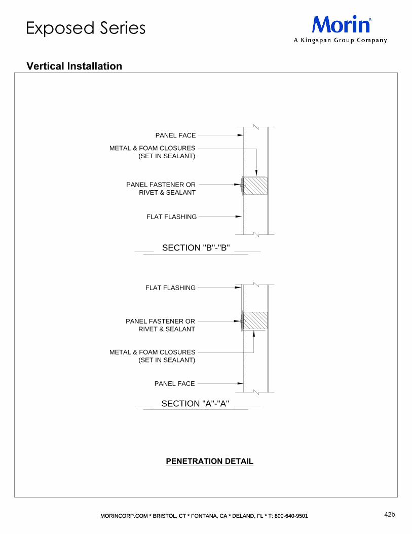
METAL & FOAM CLOSURES
(SET IN SEALANT)
FLAT FLASHING
PANEL FACE
PANEL FACE
METAL & FOAM CLOSURES
(SET IN SEALANT)
PANEL FASTENER OR
RIVET & SEALANT
FLAT FLASHING
PANEL FASTENER OR
RIVET & SEALANT
SECTION "A"-"A"
SECTION "B"-"B"
42b
PENETRATION DETAIL
MORINCORP.COM * BRISTOL, CT * FONTANA, CA * DELAND, FL * T: 800-640-9501MORINCORP.COM * BRISTOL, CT * FONTANA, CA * DELAND, FL * T: 800-640-9501
Exposed Series
Vertical Installation

FLASHING MK-E-FILLER
BELLOW WEATHER-RESISTIVE
BARRIER & AIR BARRIER (NBM)
FLEXIBLE EXPANSION FLASH
W/STAINLESS STEEL FLANGES
EXTERIOR SHEATHING (NBM)
WEATHER-RESISTIVE BARRIER
& AIR BARRIER (NBM)
RIVET & SEAL
FLASHING MK-E-16
RIVET & SEAL
1
2
" DEEP SUBGIRT
SELF-ADHERING BUTYL
FLASHING TAPE
PANEL SUPPORT (NBM)
(MIN.)
1
2
" REQD.
EXPANSION PLUS
1
4
"
4"
SEALANT (FIELD APPLIED)
FLASHING MK-E-15
1
4
" HWH TEK 3
FASTENER W/ WASHER
LAP TEK FASTENER
1
4
" HWH TEK 3 FASTENER
STAGGER THE TOP AND BOTTOM
OF SUBGIRT TO FRAMING MEMBERS
43
EXPANSION DETAIL
MORINCORP.COM * BRISTOL, CT * FONTANA, CA * DELAND, FL * T: 800-640-9501MORINCORP.COM * BRISTOL, CT * FONTANA, CA * DELAND, FL * T: 800-640-9501
Exposed Series
Vertical Installation

FLASHING MK-E-T/D CLEAT
METAL & FOAM CLOSURE
SET IN SEALANT
RIVET & SEAL
FLASHING MK-E-17
1
2
" DEEP SUBGIRT
1
2
" DEEP SUBGIRT
EXTERIOR SHEATHING (NBM)
WEATHER-RESISTIVE BARRIER
& AIR BARRIER (NBM)
PANEL SUPPORT (NBM)
2
1
2
"
2"
LAP TEK FASTENER
1
4
" HWH TEK 3
FASTENER W/ WASHER
1
4
" HWH TEK 3 FASTENER
STAGGER THE TOP AND BOTTOM
OF SUBGIRT TO FRAMING MEMBERS
44
TRANSITION DETAIL
MORINCORP.COM * BRISTOL, CT * FONTANA, CA * DELAND, FL * T: 800-640-9501MORINCORP.COM * BRISTOL, CT * FONTANA, CA * DELAND, FL * T: 800-640-9501
Exposed Series
Vertical Installation

Typical Wall Condition Layout
Coping Detail
Gravelstop Detail
Base at Curb or Edge of Slab Detail
Base at Slab Detail
Lap Detail
Door/Window/Louver Head Detail
Door/Window/Louver Sill Detail
Door/Window/Louver Jamb Detail
45
46
47
48
49
50
51
52
53
54
55
56
57
58
59
60
61
62
63
64
67
68
Horizontal Details Index
45
MORINCORP.COM * BRISTOL, CT * FONTANA, CA * DELAND, FL * T: 800-640-9501
TYPICAL WALL CONDITION LAYOUT
Exposed Series
Intersection of Head, Jamb, & Sill
Front Soffit Detail
Back Soffit Detail
Back Soffit Detail
Endwall Detail
Outside Corner (Miterseam) Detail
Outside Corner Detail
Inside Corner Detail
Penetration Detail
Deflection Joint Detail
Standard Trim
Maintenance Instructions
Appendix A:Panel Profiles & Fastening Patterns
47
48
49
63
51
52
53
46 59
62
61
55
58
56
60
50

2" MIN
5
°
M
IN
FLASHING MK-E-01
ROOFING MEMBRANE
(NBM)
FLASHING MK-E-FILLER
LAP TEK FASTENER
W/SEALANT
1
2
" SUBGIRT
WEATHER &
AIR BARRIER (NBM)
SEALANT & RIVET
FLASHING FASTENER
FLASHING MK-E-02
WOOD BLOCK (NBM)
EXTERIOR SHEATHING &
ROOF MEMBRANE (NBM)
PANEL SUPPORT (NBM)
1
4
" HWK TEK 3
FASTENER W/ WASHER
1
4
" HWH TEK 3 FASTENER
STAGGER THE TOP AND BOTTOM
OF SUBGIRT TO FRAMING MEMBERS
46
COPING DETAIL
MORINCORP.COM * BRISTOL, CT * FONTANA, CA * DELAND, FL * T: 800-640-9501MORINCORP.COM * BRISTOL, CT * FONTANA, CA * DELAND, FL * T: 800-640-9501
Exposed Series
Horizontal Installation
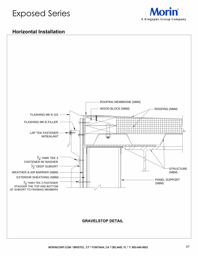
EXTERIOR SHEATHING (NBM)
WEATHER & AIR BARRIER (NBM)
1
2
" DEEP SUBGIRT
FLASHING MK-E-GS
ROOFING (NBM)
ROOFING MEMBRANE (NBM)
PANEL SUPPORT
(NBM)
STRUCTURE
(NBM)
WOOD BLOCK (NBM)
FLASHING MK-E-FILLER
LAP TEK FASTENER
W/SEALANT
1
4
" HWK TEK 3
FASTENER W/ WASHER
1
4
" HWH TEK 3 FASTENER
STAGGER THE TOP AND BOTTOM
OF SUBGIRT TO FRAMING MEMBERS
47
GRAVELSTOP DETAIL
MORINCORP.COM * BRISTOL, CT * FONTANA, CA * DELAND, FL * T: 800-640-9501MORINCORP.COM * BRISTOL, CT * FONTANA, CA * DELAND, FL * T: 800-640-9501
Exposed Series
Horizontal Installation

EXTEND WEATHER &
AIR BARRIER (NBM)
1"
EXTERIOR SHEATHING (NBM)
PANEL SUPPORT (NBM)
1
4
"
WE
EP
G
AP
1"
1
2
"
TOP/CURB
1
2
" DEEP SUBGIRT
TOP OF FLASHING
STRUCTURE (NBM)
SEALANT (NBM)
SEALANT & BACKER ROD
FLASHING MK-E-04 (STAGGER JOINTS)
1
4
" HWH TEK 3
FASTENER W/ WASHER
SELF ADHERING
BUTYL FLASHING TAPE
WEATHER & AIR
BARRIER (NBM)
1
4
" HWH TEK 3 FASTENER
STAGGER THE TOP AND BOTTOM
OF SUBGIRT TO FRAMING MEMBERS
48
BASE AT CURB OR EDGE OF SLAB DETAIL
MORINCORP.COM * BRISTOL, CT * FONTANA, CA * DELAND, FL * T: 800-640-9501MORINCORP.COM * BRISTOL, CT * FONTANA, CA * DELAND, FL * T: 800-640-9501
Exposed Series
Horizontal Installation

EXTEND WEATHER & AIR BARRIER (NBM)
STRUCTURE (NBM)
SEALANT (NBM)
FLASHING MK-E-05
1
2
"
1
4
"
WE
EP
G
AP
1
2
" DEEP SUBGIRT
SELF ADHERING
BUTYL FLASHING TAPE
WEATHER & AIR
BARRIER (NBM)
PANEL SUPPORT (NBM)
EXTERIOR SHEATHING (NBM)
1
4
" HWH TEK 3
FASTENER W/ WASHER
SUBFLASHING MK-E-05A
1
4
" HWH TEK 3 FASTENER
STAGGER THE TOP AND BOTTOM
OF SUBGIRT TO FRAMING MEMBERS
49
BASE AT SLAB DETAIL
MORINCORP.COM * BRISTOL, CT * FONTANA, CA * DELAND, FL * T: 800-640-9501MORINCORP.COM * BRISTOL, CT * FONTANA, CA * DELAND, FL * T: 800-640-9501
Exposed Series
Horizontal Installation

PANEL SUPPORT (NBM)
WEATHER & AIR
BARRIER (NBM)
4"
SUBGIRT
EXTERIOR SHEATHING (NBM)
TAPE SEALANT
LAP
1
4
" HWH TEK 3 FASTENER
STAGGER THE TOP AND BOTTOM
OF SUBGIRT TO FRAMING MEMBERS
1
4
" HWH TEK 3
FASTENER W/ WASHER
50
LAP DETAIL
MORINCORP.COM * BRISTOL, CT * FONTANA, CA * DELAND, FL * T: 800-640-9501MORINCORP.COM * BRISTOL, CT * FONTANA, CA * DELAND, FL * T: 800-640-9501
Exposed Series
Horizontal Installation
NOTE: ALL LAP CONDITIONS MUST OCCUR AT A SUPPORT POINT*NBM=(NOT BY MORIN)

1
4
"
WE
EP
GA
P
PANEL SUPPORT (NBM)
DOOR, WINDOW OR LOUVER (NBM)
PRIMARY AIR SEAL (NBM)
PER MANUFACTURER RECOMMENDATIONS
EXTEND WEATHER & AIR BARRIER (NBM)
FLASHING FASTENER
WEATHER SEAL (NBM)
1
4
" HWH TEK 3 FASTENER
STAGGER THE TOP AND BOTTOM
OF SUBGIRT TO FRAMING MEMBERS
1
4
" HWH TEK 3 FASTENER
W/ WASHER
1
2
" DEEP SUBGIRT
1
2
"
FLASHING MK-E-06
FLASHING MK-E-04
FLASHING MK-E-BT
FLASHING MK-E-FILLER
SELF ADHERING BUTYL
FLASHING TAPE
EXTERIOR SHEATHING
(NBM)
WEATHER & AIR
BARRIER (NBM)
LAP TEK FASTENER
51
DOOR/WINDOW/LOUVER HEAD
MORINCORP.COM * BRISTOL, CT * FONTANA, CA * DELAND, FL * T: 800-640-9501MORINCORP.COM * BRISTOL, CT * FONTANA, CA * DELAND, FL * T: 800-640-9501
Exposed Series
Horizontal Installation

WEATHER & AIR BARRIER (NBM)
EXTERIOR SHEATHING (NBM)
FLASHING MK-E-07
WEATHER SEAL (NBM)
LAP TEK FASTENER
W/ SEALANT
DOOR, WINDOW OR
LOUVER (NBM)
PANEL SUPPORT (NBM)
EXTEND WEATHER &
AIR BARRIER (NBM)
SEALANT & FLASHING
FASTENER
1
4
" HWH TEK 3 FASTENER
STAGGER THE TOP AND BOTTOM
OF SUBGIRT TO FRAMING MEMBERS
PRIMARY AIR SEAL (NBM) PER
MANUFACTURER RECOMMENDATIONS
1
2
"
1
4
"
1
2
" DEEP SUBGIRT
FLASHING MK-E-FILLER
1
4
" HWH TEK 3 FASTENER W/ WASHER
52
DOOR/WINDOW/LOUVER SILL
MORINCORP.COM * BRISTOL, CT * FONTANA, CA * DELAND, FL * T: 800-640-9501MORINCORP.COM * BRISTOL, CT * FONTANA, CA * DELAND, FL * T: 800-640-9501
Exposed Series
Horizontal Installation

1
2
" CLR
E/PANEL
WEATHER & AIR BARRIER (NBM)
SELF ADHERING BUTYL
FLASHING TAPE
1
4
" HWH TEK 3 FASTENER
STAGGER THE TOP AND BOTTOM
OF SUBGIRT TO FRAMING MEMBERS
FLASHING FASTENER
& SEALANT
EXTEND WEATHER &
AIR BARRIER (NBM)
DOOR, WINDOW OR LOUVER (NBM)
PRIMARY AIR SEAL (NBM)
PER MANUFACTURER RECOMMENDATIONS
PANEL SUPPORT (NBM)
WEATHER SEAL (NBM)
FLASHING MK-E-08
FLASHING MK-E-09
EXTEND INTERIOR JAMB FLASHING
BELOW SILL OPENING MIN.1/2"
ONLY REQUIRED IF WINDOW TO
BE INSTALLED BEFORE PANELS
LAP TEK FASTENER
W/ SEALANT
1
4
" HWH TEK 3 FASTENER
W/ WASHER
METAL AND FOAM CLOSURE
(SET IN SEALANT)
53
DOOR/WINDOW/LOUVER JAMB
MORINCORP.COM * BRISTOL, CT * FONTANA, CA * DELAND, FL * T: 800-640-9501MORINCORP.COM * BRISTOL, CT * FONTANA, CA * DELAND, FL * T: 800-640-9501
Exposed Series
Horizontal Installation

SELF ADHERING BUTYL
FLASHING TAPE
HEAD FLASH
JAMB FLASH
NON-CURING BUTYL
STUDS (NBM)
NON-CURING BUTYL
EXTERIOR SHEATHING (NBM)
EXTERIOR SHEATHING (NBM)
FIELD TAB
SEAL JOINTS & REVEALS
NON-CURING BUTYL
ERECTOR NOTE:
FIELD PROVIDE END DAM
AT HEAD CONDITION.
SEAL AS REQUIRED.
SILL FLASHING
SUBGIRT
WEATHER &
AIR BARRIER (NBM)
WEATHER & AIR BARRIER (NBM)
54
INTERSECTION OF HEAD/JAMB/SILL
MORINCORP.COM * BRISTOL, CT * FONTANA, CA * DELAND, FL * T: 800-640-9501MORINCORP.COM * BRISTOL, CT * FONTANA, CA * DELAND, FL * T: 800-640-9501
Exposed Series
Horizontal Installation

LAP TEK FASTENER
FLASHING MK-E-04
(STAGGER JOINTS)
1
2
"
FLASHING MK-E-10
1
4
"
WE
EP
G
AP
FLASHING MK-E-BT
FLASHING MK-E-FILLER
WEATHER & AIR
BARRIER (NBM)
EXTERIOR
SHEATHING (NBM)
1
4
" HWH TEK 3
FASTENER W/ WASHER
SUBGIRT
PANEL SUPPORT (NBM)
1
4
" HWH TEK 3 FASTENER
BUTYL FLASHING TAPE
55
FRONT SOFFIT DETAIL
MORINCORP.COM * BRISTOL, CT * FONTANA, CA * DELAND, FL * T: 800-640-9501MORINCORP.COM * BRISTOL, CT * FONTANA, CA * DELAND, FL * T: 800-640-9501
Exposed Series
Horizontal Installation

PANEL SUPPORT (NBM)
FLASHING MK-E-11
METAL AND FOAM CLOSURE
LAP TEK FASTENER
EXTERIOR SHEATHING (NBM)
WEATHER & AIR BARRIER (NBM)
1
4
" HWH TEK 3
FASTENER W/ WASHER
1
2
" DEEP SUBGIRT
1
4
" HWH TEK 3 FASTENER
STAGGER THE TOP AND BOTTOM
OF SUBGIRT TO FRAMING MEMBER
56
BACK SOFFIT DETAIL
MORINCORP.COM * BRISTOL, CT * FONTANA, CA * DELAND, FL * T: 800-640-9501MORINCORP.COM * BRISTOL, CT * FONTANA, CA * DELAND, FL * T: 800-640-9501
Exposed Series
Horizontal Installation

LAP TEK FASTENER
FLASHING MK-E-14
MK-E-FILLER
EXTERIOR SHEATHING (NBM)
WEATHER & AIR BARRIER (NBM)
1
4
" HWH TEK 3 FASTENER
STAGGER THE TOP AND BOTTOM
OF SUBGIRT TO FRAMING MEMBERS
1
4
" HWH TEK 3
FASTENER W/ WASHER
1
2
" DEEP SUBGIRT
PANEL SUPPORT (NBM)
57
BACK SOFFIT DETAIL
MORINCORP.COM * BRISTOL, CT * FONTANA, CA * DELAND, FL * T: 800-640-9501MORINCORP.COM * BRISTOL, CT * FONTANA, CA * DELAND, FL * T: 800-640-9501
Exposed Series
Horizontal Installation

PANEL SUPPORT (NBM)
STRUCTURE (NBM)
SEALANT
EXTEND WEATHER &
AIR BARRIER (NBM)
1
4
" HWH TEK 3
FASTENER W/WASHER
FLASHING MK-E-12
LAP TEK FASTENER
W/SEALANT
1
2
" DEEP SUBGIRT
WEATHER & AIR BARRIER (NBM)
EXTERIOR SHEATHING (NBM)
1
4
" HWH TEK 3 FASTENER
STAGGER THE TOP AND BOTTOM
OF SUBGIRT TO FRAMING MEMBERS
1
1
2
"
METAL AND FOAM
CLOSURE (SET IN SEALANT)
58
ENDWALL DETAIL
MORINCORP.COM * BRISTOL, CT * FONTANA, CA * DELAND, FL * T: 800-640-9501MORINCORP.COM * BRISTOL, CT * FONTANA, CA * DELAND, FL * T: 800-640-9501
Exposed Series
Horizontal Installation

SHOP ASSEMBLED
24" X 24" MITERSEAM
CORNER PANEL
WEATHER & AIR BARRIER (NBM)
EXTERIOR SHEATHING (NBM)
1
4
" HWH TEK 3 FASTENER
STAGGER THE TOP AND BOTTOM
OF SUBGIRT TO FRAMING MEMBER
PANEL SUPPORT (NBM)
1
2
" DEEP SUBGIRT
1
4
" HWH TEK 3 FASTENER
W/ WASHER
I.S. FOAM CLOSURE SET IN SEALANT
59
OUTSIDE CORNER (MITERSEAM) DETAIL
MORINCORP.COM * BRISTOL, CT * FONTANA, CA * DELAND, FL * T: 800-640-9501MORINCORP.COM * BRISTOL, CT * FONTANA, CA * DELAND, FL * T: 800-640-9501
Exposed Series
Horizontal Installation
*CORNER TO BE INSTALLED
AT SAME TIME AS PANELS

1
2
" DEEP SUBGIRT
WEATHER & AIR BARRIER (NBM)
EXTERIOR SHEATHING (NBM)
1
4
" HWH TEK 3 FASTENER
W/ WASHER
PANEL SUPPORT (NBM)
END/PANEL
1
2
"
MK-E-13B
LAP TEK FASTENER
W/ SEALANT
METAL AND FOAM CLOSURE
(SET IN SEALANT)
1
4
" HWH TEK 3 FASTENER
STAGGER THE TOP AND BOTTOM
OF SUBGIRT TO FRAMING MEMBERS
60
OUTSIDE CORNER DETAIL
MORINCORP.COM * BRISTOL, CT * FONTANA, CA * DELAND, FL * T: 800-640-9501MORINCORP.COM * BRISTOL, CT * FONTANA, CA * DELAND, FL * T: 800-640-9501
Exposed Series
Horizontal Installation

LAP TEK FASTENER
W/ SEALANT
FLASHING MK-E-14
WEATHER & AIR BARRIER (NBM)
EXTERIOR SHEATHING (NBM)
1
2
" DEEP SUBGIRT
PANEL SUPPORT (NBM)
METAL AND FOAM CLOSURE
(SET IN SEALANT)
1
4
" HWH TEK 3 FASTENER
STAGGER THE TOP AND BOTTOM
OF SUBGIRT TO FRAMING MEMBERS
1
4
" HWH TEK 3 FASTENER
W/ WASHER
61
INSIDE CORNER DETAIL
MORINCORP.COM * BRISTOL, CT * FONTANA, CA * DELAND, FL * T: 800-640-9501MORINCORP.COM * BRISTOL, CT * FONTANA, CA * DELAND, FL * T: 800-640-9501
Exposed Series
Horizontal Installation

EXTERIOR
SHEATHING (NBM)
SUBGIRT
WEATHER &
AIR BARRIER (NBM)
FLAT FLASHING
LAP TEK 3 FASTENER
W/WASHER
SEALANT
METAL AND FOAM
CLOSURE (SET IN SEALANT)
62
PENETRATION DETAIL
MORINCORP.COM * BRISTOL, CT * FONTANA, CA * DELAND, FL * T: 800-640-9501MORINCORP.COM * BRISTOL, CT * FONTANA, CA * DELAND, FL * T: 800-640-9501
Exposed Series
Horizontal Installation

WEATHER & AIR BARRIER (NBM)
1
2
" DEEP SUBGIRT
EXTERIOR SHEATHING (NBM)
FLASHING MK-E-DEF TRIM
1
4
" HWH TEK 3 FASTENER
STAGGER THE TOP AND BOTTOM
OF SUBGIRT TO FRAMING MEMBERS
FLASHING MK-E-T/D CLEAT
1
2
"
FLASHING MK-E-FILLER
1
2
" DEEP SUBGIRT
1
2
" GAP (FLOOR TO T.O. PANEL)
AMOUNT OF DEFLECTION
FLOOR LINE (NBM)
WILL ALLOW FOR
REQUIRED DEFLECTION
1
4
" HWH TEK 3 FASTENER
W/ WASHER
LAP TEK FASTENER
RIVET
63
DEFLECTION DETAIL
MORINCORP.COM * BRISTOL, CT * FONTANA, CA * DELAND, FL * T: 800-640-9501MORINCORP.COM * BRISTOL, CT * FONTANA, CA * DELAND, FL * T: 800-640-9501
Exposed Series
Horizontal Installation

64
COPING DETAIL
MORINCORP.COM * BRISTOL, CT * FONTANA, CA * DELAND, FL * T: 800-640-9501MORINCORP.COM * BRISTOL, CT * FONTANA, CA * DELAND, FL * T: 800-640-9501
O.H.
F.S.
F.S.
MK-E-01
F.S.
(OPTIONAL ONE-PIECE TRIM)
O.H.
O.H.
MK-E-02
MK-E-03
COPING DETAIL
COPING DETAIL
F.S.
O.H.
MK-E-GS
GRAVELSTOP DETAIL
COMMON TRIM AT VARIOUS DETAILS
F.S.
MK-MX-FILLER
Exposed Series:Standard Trim
MK-E-04
BASE AT CURB DETAIL
DOOR/WINDOW/LOUVER HEAD
FRONT SOFFIT DETAIL
F.S.
O.H.
COMMON TRIM AT VARIOUS DETAILS
F.S.
MK-MX-BT
MK-E-05
BASE AT SLAB DETAIL
F.S.
T.H.
T.H.

65
BASE AT SLAB DETAIL
MORINCORP.COM * BRISTOL, CT * FONTANA, CA * DELAND, FL * T: 800-640-9501MORINCORP.COM * BRISTOL, CT * FONTANA, CA * DELAND, FL * T: 800-640-9501
MK-E-05A
MK-E-06
MK-E-07
DOOR/WINOW/LOUVER HEAD
DOOR/WINDOW/LOUVER SILL
MK-E-08
MK-E-09
MK-E-10
MK-E-11
DOOR/WINDOW/LOUVER JAMB
FRONT SOFFIT DETAIL
F.S.
F.S.
F.S.
O.H.
F.S.
T.H.
DOOR/WINDOW/LOUVER JAMB
(20GA MIN.)
F.S.
F.S.T.H.
F.S.
T.H.
BACK SOFFIT DETAIL
Exposed Series:Standard Trim
MK-E-12
ENDWALL DETAIL
F.S.
T.H.

66
MORINCORP.COM * BRISTOL, CT * FONTANA, CA * DELAND, FL * T: 800-640-9501MORINCORP.COM * BRISTOL, CT * FONTANA, CA * DELAND, FL * T: 800-640-9501
MK-E-13A (VERTICAL)
MK-E-14
MK-E-15
EXPANSION DETAIL
TRANSITION DETAIL
T.H.
F.S.
T.H.
F.S.
OUTSIDE CORNER
INSIDE CORNER DETAIL
T.H.
T.H.
O.H.
O.H.
F.S.
F.S.
Exposed Series:Standard Trim
MK-MX-16
TRANSITION/DEFLECTION DETAIL
1
4
6
°
F.S.
MK-E-17
MK-E-T/D CLEAT
F.S.
O.H.
MK-E-DEF TRIM
DEFLECTION DETAIL
EXPANSION DETAIL
T.H.
F.S.
OUTSIDE CORNER
MK-E-13B (HORIZONTAL)
O.H.
T.H.

67
MORINCORP.COM * BRISTOL, CT * FONTANA, CA * DELAND, FL * T: 800-640-9501MORINCORP.COM * BRISTOL, CT * FONTANA, CA * DELAND, FL * T: 800-640-9501
Maintenance Instructions
Exposed Series
METAL WALL/ROOF PANELS NORMALLY REQUIRE A MINIMUM OF MAINTENANCE. TO PROVIDE A
GREATER DEGREE OF OPTIMUM SERVICE LIFE, THE OWNER'S MAINTENANCE DEPARTMENT SHOULD
INSPECT THE PANEL SURFACE BI-ANNUALLY, PREFERABLY DURING THE SPRING AND FALL OR AFTER
ANY SEVERE STORMS.
1. The Owner's Agent shall note or do the following:
A.File all project records, shop drawings, project plans and specifications for reference. Set up a
maintenance schedule and written reporting documentation system.
B. Clean drains, gutters, copings and inspect sealants at all locations.
C. Clean USING NORMAL WATER PRESSURE any accumulated airborne or waterborne contaminants
that aren't being naturally removed. DO NOT use any cleaning agents, abrasives or detergents without
consulting Morin. Rinse to avoid cleaning residues. When possible, do not direct water at a panel side
lap or any seams. Systematic fresh water rinse maintenance shall be in effect in areas of high salt
concentration (such as adjacent to the seashore and/or in industrial atmosphere) so as to prevent the
accumulation of concentrated salt deposits. We require a documented inspection and bi-annual fresh
water rinse of exposed panel system be sent each time conducted to Morin. (Documented inspection
and rinse - include date performed, notes of any areas of concern [items E, F, G, and H below] and
pictures, clean water wash with regular pressure for 5 minutes per area of cleaning, sign and date the
document with all parties involved.) Morin must be contacted prior to inspection to be given the option
of attending. Contact Morin Technical Department 800-640-9501, 685 Middle Street, Bristol, CT 06010.
D. Inspect for any standing water at flashings or panels. See note 2.
E. Observe and remove any vegetation or debris that has accumulated against
the panels.
F. Examine for any deterioration, pest disturbance or vandalism at sealants, closures, flashings and
panels. See note 2.
G. View panel surface at all penetrations for any localized deterioration. See note 2.
H. Notify contractor of any leaks. Note the location and conditions resulting
in leakage; magnitude of rain; wind direction; temperature; time required for leaks to appear and cease
after rain starts and stops; condition of building openings; status of mechanical equipment; internal
conditions, windows, walls and skylights, etc.
I. Keep written documentation of the location and type of any deterioration
for future yearly comparisons.
1. Except for emergencies or obvious problems, do not perform any repairs on any issues note above.
Consult with the contractor for proper remedial action (if any).
2. All servicing of the panel system must be completed in compliance with the above or voiding of any or all
warranties may occur.

BR-28 FASTENING PATTERN
SIDE A
BR-28 FASTENING PATTERN
SIDE B
SIDE A
SIDE B
68
MORINCORP.COM * BRISTOL, CT * FONTANA, CA * DELAND, FL * T: 800-640-9501MORINCORP.COM * BRISTOL, CT * FONTANA, CA * DELAND, FL * T: 800-640-9501
Appendix A:
Exposed Fastener Series Profiles with Fastening Patterns
Exposed Series
BR-28

FINISH
SIDE
FINISH
SIDE
BR-35 FASTENING PATTERN
SIDE A
BR-35 FASTENING PATTERN
SIDE B
SIDE A
SIDE B
69
MORINCORP.COM * BRISTOL, CT * FONTANA, CA * DELAND, FL * T: 800-640-9501MORINCORP.COM * BRISTOL, CT * FONTANA, CA * DELAND, FL * T: 800-640-9501
Appendix A:
Exposed Fastener Series Profiles with Fastening Patterns
Exposed Series
BR-35

BR7-35 FASTENING PATTERN
SIDE A
BR7-35 FASTENING PATTERN
SIDE B
SIDE A
SIDE B
70
MORINCORP.COM * BRISTOL, CT * FONTANA, CA * DELAND, FL * T: 800-640-9501MORINCORP.COM * BRISTOL, CT * FONTANA, CA * DELAND, FL * T: 800-640-9501
Appendix A:
Exposed Fastener Series Profiles with Fastening Patterns
Exposed Series
BR7-35
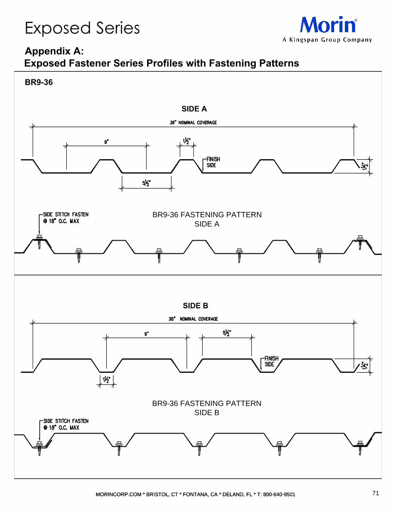
BR9-36 FASTENING PATTERN
SIDE A
BR9-36 FASTENING PATTERN
SIDE B
SIDE A
SIDE B
71
MORINCORP.COM * BRISTOL, CT * FONTANA, CA * DELAND, FL * T: 800-640-9501MORINCORP.COM * BRISTOL, CT * FONTANA, CA * DELAND, FL * T: 800-640-9501
Appendix A:
Exposed Fastener Series Profiles with Fastening Patterns
Exposed Series
BR9-36

C-29 FASTENING PATTERN
SIDE A
C-29 FASTENING PATTERN
SIDE B
SIDE A
SIDE B
72
MORINCORP.COM * BRISTOL, CT * FONTANA, CA * DELAND, FL * T: 800-640-9501MORINCORP.COM * BRISTOL, CT * FONTANA, CA * DELAND, FL * T: 800-640-9501
Appendix A:
Exposed Fastener Series Profiles with Fastening Patterns
Exposed Series
C-29
NOTE: FASTEN EVERY CELL @ PANEL ENDS AND LAPS

C-37 FASTENING PATTERN
SIDE A
C-37 FASTENING PATTERN
SIDE B
SIDE A
SIDE B
73
MORINCORP.COM * BRISTOL, CT * FONTANA, CA * DELAND, FL * T: 800-640-9501MORINCORP.COM * BRISTOL, CT * FONTANA, CA * DELAND, FL * T: 800-640-9501
Appendix A:
Exposed Fastener Series Profiles with Fastening Patterns
Exposed Series
C-37
NOTE: FASTEN EVERY CELL @ PANEL ENDS AND LAPS

C-40 FASTENING PATTERN
SIDE A
C-40 FASTENING PATTERN
SIDE B
SIDE A
SIDE B
74
MORINCORP.COM * BRISTOL, CT * FONTANA, CA * DELAND, FL * T: 800-640-9501MORINCORP.COM * BRISTOL, CT * FONTANA, CA * DELAND, FL * T: 800-640-9501
Appendix A:
Exposed Fastener Series Profiles with Fastening Patterns
Exposed Series
C-40
NOTE: FASTEN EVERY CELL @ PANEL ENDS AND LAPS

E-36 FASTENING PATTERN
SIDE A
E-36 FASTENING PATTERN
SIDE B
SIDE A
SIDE B
75
MORINCORP.COM * BRISTOL, CT * FONTANA, CA * DELAND, FL * T: 800-640-9501MORINCORP.COM * BRISTOL, CT * FONTANA, CA * DELAND, FL * T: 800-640-9501
Appendix A:
Exposed Fastener Series Profiles with Fastening Patterns
Exposed Series
E-36
NOTE: FASTEN EVERY CELL @ PANEL ENDS AND LAPS

E8-40 FASTENING PATTERN
SIDE A
E8-40 FASTENING PATTERN
SIDE B
SIDE A
SIDE B
76
MORINCORP.COM * BRISTOL, CT * FONTANA, CA * DELAND, FL * T: 800-640-9501MORINCORP.COM * BRISTOL, CT * FONTANA, CA * DELAND, FL * T: 800-640-9501
Appendix A:
Exposed Fastener Series Profiles with Fastening Patterns
Exposed Series
E8-40

MR-36 FASTENING PATTERN
SIDE A
MR-36 FASTENING PATTERN
SIDE B
SIDE A
SIDE B
77
MORINCORP.COM * BRISTOL, CT * FONTANA, CA * DELAND, FL * T: 800-640-9501MORINCORP.COM * BRISTOL, CT * FONTANA, CA * DELAND, FL * T: 800-640-9501
Appendix A:
Exposed Fastener Series Profiles with Fastening Patterns
Exposed Series
MR-36
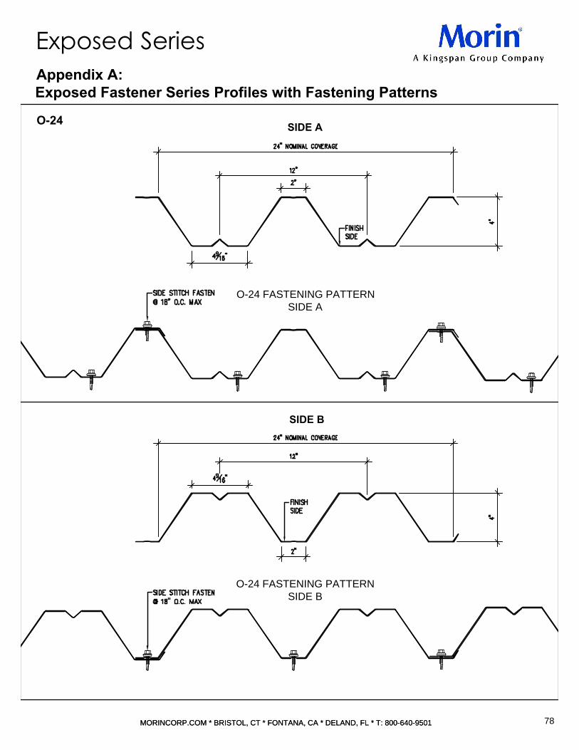
O-24 FASTENING PATTERN
SIDE A
O-24 FASTENING PATTERN
SIDE B
SIDE A
SIDE B
78
MORINCORP.COM * BRISTOL, CT * FONTANA, CA * DELAND, FL * T: 800-640-9501MORINCORP.COM * BRISTOL, CT * FONTANA, CA * DELAND, FL * T: 800-640-9501
Appendix A:
Exposed Fastener Series Profiles with Fastening Patterns
Exposed Series
O-24

O-24W FASTENING PATTERN
SIDE A
O-24W FASTENING PATTERN
SIDE B
SIDE A
SIDE B
79
MORINCORP.COM * BRISTOL, CT * FONTANA, CA * DELAND, FL * T: 800-640-9501MORINCORP.COM * BRISTOL, CT * FONTANA, CA * DELAND, FL * T: 800-640-9501
Appendix A:
Exposed Fastener Series Profiles with Fastening Patterns
Exposed Series
O-24W

U-24 FASTENING PATTERN
SIDE A
U-24 FASTENING PATTERN
SIDE B
SIDE A
SIDE B
80
MORINCORP.COM * BRISTOL, CT * FONTANA, CA * DELAND, FL * T: 800-640-9501MORINCORP.COM * BRISTOL, CT * FONTANA, CA * DELAND, FL * T: 800-640-9501
Appendix A:
Exposed Fastener Series Profiles with Fastening Patterns
Exposed Series
U-24

VB-31 FASTENING PATTERN
SIDE A
VB-31 FASTENING PATTERN
SIDE B
SIDE A
SIDE B
81
MORINCORP.COM * BRISTOL, CT * FONTANA, CA * DELAND, FL * T: 800-640-9501MORINCORP.COM * BRISTOL, CT * FONTANA, CA * DELAND, FL * T: 800-640-9501
Appendix A:
Exposed Fastener Series Profiles with Fastening Patterns
Exposed Series
VB-31
NOTE: FASTEN EVERY CELL @ PANEL ENDS AND LAPS

VB-36 FASTENING PATTERN
SIDE A
VB-36 FASTENING PATTERN
SIDE B
SIDE A
SIDE B
82
MORINCORP.COM * BRISTOL, CT * FONTANA, CA * DELAND, FL * T: 800-640-9501MORINCORP.COM * BRISTOL, CT * FONTANA, CA * DELAND, FL * T: 800-640-9501
Appendix A:
Exposed Fastener Series Profiles with Fastening Patterns
Exposed Series
VB-36
NOTE: FASTEN EVERY CELL @ PANEL ENDS AND LAPS
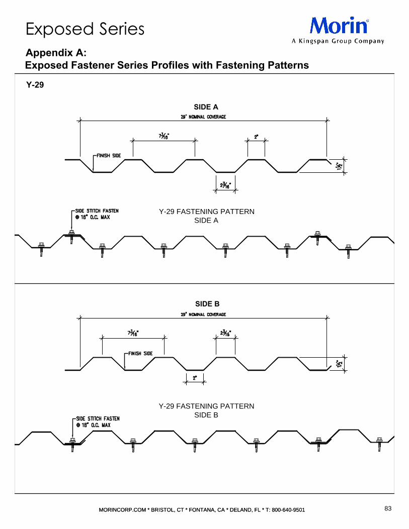
Y-29 FASTENING PATTERN
SIDE A
Y-29 FASTENING PATTERN
SIDE B
SIDE A
SIDE B
83
MORINCORP.COM * BRISTOL, CT * FONTANA, CA * DELAND, FL * T: 800-640-9501MORINCORP.COM * BRISTOL, CT * FONTANA, CA * DELAND, FL * T: 800-640-9501
Appendix A:
Exposed Fastener Series Profiles with Fastening Patterns
Exposed Series
Y-29

Y-36 FASTENING PATTERN
SIDE A
Y-36 FASTENING PATTERN
SIDE B
SIDE A
SIDE B
84
MORINCORP.COM * BRISTOL, CT * FONTANA, CA * DELAND, FL * T: 800-640-9501MORINCORP.COM * BRISTOL, CT * FONTANA, CA * DELAND, FL * T: 800-640-9501
Appendix A:
Exposed Fastener Series Profiles with Fastening Patterns
Exposed Series
Y-36

Y-36 FASTENING PATTERN
SIDE A
Y-36 FASTENING PATTERN
SIDE B
SIDE A
SIDE B
85
MORINCORP.COM * BRISTOL, CT * FONTANA, CA * DELAND, FL * T: 800-640-9501MORINCORP.COM * BRISTOL, CT * FONTANA, CA * DELAND, FL * T: 800-640-9501
Appendix A:
Exposed Fastener Series Profiles with Fastening Patterns
Exposed Series
*NBM=(NOT BY MORIN)
Y-36